US5586675A - Reinforced material handling container - Google Patents
Reinforced material handling containerDownload PDFInfo
- Publication number
- US5586675A US5586675AUS08/159,095US15909593AUS5586675AUS 5586675 AUS5586675 AUS 5586675AUS 15909593 AUS15909593 AUS 15909593AUS 5586675 AUS5586675 AUS 5586675A
- Authority
- US
- United States
- Prior art keywords
- container
- walls
- planer
- base
- material handling
- Prior art date
- Legal status (The legal status is an assumption and is not a legal conclusion. Google has not performed a legal analysis and makes no representation as to the accuracy of the status listed.)
- Expired - Lifetime
Links
Images


Classifications
- B—PERFORMING OPERATIONS; TRANSPORTING
- B65—CONVEYING; PACKING; STORING; HANDLING THIN OR FILAMENTARY MATERIAL
- B65D—CONTAINERS FOR STORAGE OR TRANSPORT OF ARTICLES OR MATERIALS, e.g. BAGS, BARRELS, BOTTLES, BOXES, CANS, CARTONS, CRATES, DRUMS, JARS, TANKS, HOPPERS, FORWARDING CONTAINERS; ACCESSORIES, CLOSURES, OR FITTINGS THEREFOR; PACKAGING ELEMENTS; PACKAGES
- B65D19/00—Pallets or like platforms, with or without side walls, for supporting loads to be lifted or lowered
- B65D19/02—Rigid pallets with side walls, e.g. box pallets
- B65D19/06—Rigid pallets with side walls, e.g. box pallets with bodies formed by uniting or interconnecting two or more components
- B65D19/18—Rigid pallets with side walls, e.g. box pallets with bodies formed by uniting or interconnecting two or more components made wholly or mainly of plastics material
- B—PERFORMING OPERATIONS; TRANSPORTING
- B65—CONVEYING; PACKING; STORING; HANDLING THIN OR FILAMENTARY MATERIAL
- B65D—CONTAINERS FOR STORAGE OR TRANSPORT OF ARTICLES OR MATERIALS, e.g. BAGS, BARRELS, BOTTLES, BOXES, CANS, CARTONS, CRATES, DRUMS, JARS, TANKS, HOPPERS, FORWARDING CONTAINERS; ACCESSORIES, CLOSURES, OR FITTINGS THEREFOR; PACKAGING ELEMENTS; PACKAGES
- B65D11/00—Containers having bodies formed by interconnecting or uniting two or more rigid, or substantially rigid, components made wholly or mainly of plastics material
- B65D11/18—Containers having bodies formed by interconnecting or uniting two or more rigid, or substantially rigid, components made wholly or mainly of plastics material collapsible, i.e. with walls hinged together or detachably connected
- B65D11/1833—Containers having bodies formed by interconnecting or uniting two or more rigid, or substantially rigid, components made wholly or mainly of plastics material collapsible, i.e. with walls hinged together or detachably connected whereby all side walls are hingedly connected to the base panel
- B—PERFORMING OPERATIONS; TRANSPORTING
- B65—CONVEYING; PACKING; STORING; HANDLING THIN OR FILAMENTARY MATERIAL
- B65D—CONTAINERS FOR STORAGE OR TRANSPORT OF ARTICLES OR MATERIALS, e.g. BAGS, BARRELS, BOTTLES, BOXES, CANS, CARTONS, CRATES, DRUMS, JARS, TANKS, HOPPERS, FORWARDING CONTAINERS; ACCESSORIES, CLOSURES, OR FITTINGS THEREFOR; PACKAGING ELEMENTS; PACKAGES
- B65D25/00—Details of other kinds or types of rigid or semi-rigid containers
- B65D25/005—Side walls formed with an aperture or a movable portion arranged to allow removal or insertion of contents
- B—PERFORMING OPERATIONS; TRANSPORTING
- B65—CONVEYING; PACKING; STORING; HANDLING THIN OR FILAMENTARY MATERIAL
- B65D—CONTAINERS FOR STORAGE OR TRANSPORT OF ARTICLES OR MATERIALS, e.g. BAGS, BARRELS, BOTTLES, BOXES, CANS, CARTONS, CRATES, DRUMS, JARS, TANKS, HOPPERS, FORWARDING CONTAINERS; ACCESSORIES, CLOSURES, OR FITTINGS THEREFOR; PACKAGING ELEMENTS; PACKAGES
- B65D2519/00—Pallets or like platforms, with or without side walls, for supporting loads to be lifted or lowered
- B65D2519/00004—Details relating to pallets
- B65D2519/00009—Materials
- B65D2519/00014—Materials for the load supporting surface
- B65D2519/00034—Plastic
- B—PERFORMING OPERATIONS; TRANSPORTING
- B65—CONVEYING; PACKING; STORING; HANDLING THIN OR FILAMENTARY MATERIAL
- B65D—CONTAINERS FOR STORAGE OR TRANSPORT OF ARTICLES OR MATERIALS, e.g. BAGS, BARRELS, BOTTLES, BOXES, CANS, CARTONS, CRATES, DRUMS, JARS, TANKS, HOPPERS, FORWARDING CONTAINERS; ACCESSORIES, CLOSURES, OR FITTINGS THEREFOR; PACKAGING ELEMENTS; PACKAGES
- B65D2519/00—Pallets or like platforms, with or without side walls, for supporting loads to be lifted or lowered
- B65D2519/00004—Details relating to pallets
- B65D2519/00009—Materials
- B65D2519/00049—Materials for the base surface
- B65D2519/00069—Plastic
- B—PERFORMING OPERATIONS; TRANSPORTING
- B65—CONVEYING; PACKING; STORING; HANDLING THIN OR FILAMENTARY MATERIAL
- B65D—CONTAINERS FOR STORAGE OR TRANSPORT OF ARTICLES OR MATERIALS, e.g. BAGS, BARRELS, BOTTLES, BOXES, CANS, CARTONS, CRATES, DRUMS, JARS, TANKS, HOPPERS, FORWARDING CONTAINERS; ACCESSORIES, CLOSURES, OR FITTINGS THEREFOR; PACKAGING ELEMENTS; PACKAGES
- B65D2519/00—Pallets or like platforms, with or without side walls, for supporting loads to be lifted or lowered
- B65D2519/00004—Details relating to pallets
- B65D2519/00009—Materials
- B65D2519/00119—Materials for the construction of the reinforcements
- B65D2519/00139—Plastic
- B—PERFORMING OPERATIONS; TRANSPORTING
- B65—CONVEYING; PACKING; STORING; HANDLING THIN OR FILAMENTARY MATERIAL
- B65D—CONTAINERS FOR STORAGE OR TRANSPORT OF ARTICLES OR MATERIALS, e.g. BAGS, BARRELS, BOTTLES, BOXES, CANS, CARTONS, CRATES, DRUMS, JARS, TANKS, HOPPERS, FORWARDING CONTAINERS; ACCESSORIES, CLOSURES, OR FITTINGS THEREFOR; PACKAGING ELEMENTS; PACKAGES
- B65D2519/00—Pallets or like platforms, with or without side walls, for supporting loads to be lifted or lowered
- B65D2519/00004—Details relating to pallets
- B65D2519/00258—Overall construction
- B65D2519/00263—Overall construction of the pallet
- B65D2519/00268—Overall construction of the pallet made of one piece
- B—PERFORMING OPERATIONS; TRANSPORTING
- B65—CONVEYING; PACKING; STORING; HANDLING THIN OR FILAMENTARY MATERIAL
- B65D—CONTAINERS FOR STORAGE OR TRANSPORT OF ARTICLES OR MATERIALS, e.g. BAGS, BARRELS, BOTTLES, BOXES, CANS, CARTONS, CRATES, DRUMS, JARS, TANKS, HOPPERS, FORWARDING CONTAINERS; ACCESSORIES, CLOSURES, OR FITTINGS THEREFOR; PACKAGING ELEMENTS; PACKAGES
- B65D2519/00—Pallets or like platforms, with or without side walls, for supporting loads to be lifted or lowered
- B65D2519/00004—Details relating to pallets
- B65D2519/00258—Overall construction
- B65D2519/00283—Overall construction of the load supporting surface
- B65D2519/00288—Overall construction of the load supporting surface made of one piece
- B—PERFORMING OPERATIONS; TRANSPORTING
- B65—CONVEYING; PACKING; STORING; HANDLING THIN OR FILAMENTARY MATERIAL
- B65D—CONTAINERS FOR STORAGE OR TRANSPORT OF ARTICLES OR MATERIALS, e.g. BAGS, BARRELS, BOTTLES, BOXES, CANS, CARTONS, CRATES, DRUMS, JARS, TANKS, HOPPERS, FORWARDING CONTAINERS; ACCESSORIES, CLOSURES, OR FITTINGS THEREFOR; PACKAGING ELEMENTS; PACKAGES
- B65D2519/00—Pallets or like platforms, with or without side walls, for supporting loads to be lifted or lowered
- B65D2519/00004—Details relating to pallets
- B65D2519/00258—Overall construction
- B65D2519/00313—Overall construction of the base surface
- B65D2519/00318—Overall construction of the base surface made of one piece
- B—PERFORMING OPERATIONS; TRANSPORTING
- B65—CONVEYING; PACKING; STORING; HANDLING THIN OR FILAMENTARY MATERIAL
- B65D—CONTAINERS FOR STORAGE OR TRANSPORT OF ARTICLES OR MATERIALS, e.g. BAGS, BARRELS, BOTTLES, BOXES, CANS, CARTONS, CRATES, DRUMS, JARS, TANKS, HOPPERS, FORWARDING CONTAINERS; ACCESSORIES, CLOSURES, OR FITTINGS THEREFOR; PACKAGING ELEMENTS; PACKAGES
- B65D2519/00—Pallets or like platforms, with or without side walls, for supporting loads to be lifted or lowered
- B65D2519/00004—Details relating to pallets
- B65D2519/00258—Overall construction
- B65D2519/00313—Overall construction of the base surface
- B65D2519/00328—Overall construction of the base surface shape of the contact surface of the base
- B65D2519/00348—Overall construction of the base surface shape of the contact surface of the base contact surface of other form
- B—PERFORMING OPERATIONS; TRANSPORTING
- B65—CONVEYING; PACKING; STORING; HANDLING THIN OR FILAMENTARY MATERIAL
- B65D—CONTAINERS FOR STORAGE OR TRANSPORT OF ARTICLES OR MATERIALS, e.g. BAGS, BARRELS, BOTTLES, BOXES, CANS, CARTONS, CRATES, DRUMS, JARS, TANKS, HOPPERS, FORWARDING CONTAINERS; ACCESSORIES, CLOSURES, OR FITTINGS THEREFOR; PACKAGING ELEMENTS; PACKAGES
- B65D2519/00—Pallets or like platforms, with or without side walls, for supporting loads to be lifted or lowered
- B65D2519/00004—Details relating to pallets
- B65D2519/00547—Connections
- B65D2519/00636—Connections structures connecting side walls to the pallet
- B65D2519/00641—Structures intended to be disassembled
- B65D2519/00646—Structures intended to be disassembled by means of hinges
- B—PERFORMING OPERATIONS; TRANSPORTING
- B65—CONVEYING; PACKING; STORING; HANDLING THIN OR FILAMENTARY MATERIAL
- B65D—CONTAINERS FOR STORAGE OR TRANSPORT OF ARTICLES OR MATERIALS, e.g. BAGS, BARRELS, BOTTLES, BOXES, CANS, CARTONS, CRATES, DRUMS, JARS, TANKS, HOPPERS, FORWARDING CONTAINERS; ACCESSORIES, CLOSURES, OR FITTINGS THEREFOR; PACKAGING ELEMENTS; PACKAGES
- B65D2519/00—Pallets or like platforms, with or without side walls, for supporting loads to be lifted or lowered
- B65D2519/00004—Details relating to pallets
- B65D2519/00736—Details
- B65D2519/00805—Means for facilitating the removal of the load
- B—PERFORMING OPERATIONS; TRANSPORTING
- B65—CONVEYING; PACKING; STORING; HANDLING THIN OR FILAMENTARY MATERIAL
- B65D—CONTAINERS FOR STORAGE OR TRANSPORT OF ARTICLES OR MATERIALS, e.g. BAGS, BARRELS, BOTTLES, BOXES, CANS, CARTONS, CRATES, DRUMS, JARS, TANKS, HOPPERS, FORWARDING CONTAINERS; ACCESSORIES, CLOSURES, OR FITTINGS THEREFOR; PACKAGING ELEMENTS; PACKAGES
- B65D2519/00—Pallets or like platforms, with or without side walls, for supporting loads to be lifted or lowered
- B65D2519/00004—Details relating to pallets
- B65D2519/00736—Details
- B65D2519/00865—Collapsible, i.e. at least two constitutive elements remaining hingedly connected
- B65D2519/00875—Collapsible, i.e. at least two constitutive elements remaining hingedly connected collapsible side walls
- B65D2519/009—Collapsible, i.e. at least two constitutive elements remaining hingedly connected collapsible side walls whereby all side walls are hingedly connected to the base panel
- B—PERFORMING OPERATIONS; TRANSPORTING
- B65—CONVEYING; PACKING; STORING; HANDLING THIN OR FILAMENTARY MATERIAL
- B65D—CONTAINERS FOR STORAGE OR TRANSPORT OF ARTICLES OR MATERIALS, e.g. BAGS, BARRELS, BOTTLES, BOXES, CANS, CARTONS, CRATES, DRUMS, JARS, TANKS, HOPPERS, FORWARDING CONTAINERS; ACCESSORIES, CLOSURES, OR FITTINGS THEREFOR; PACKAGING ELEMENTS; PACKAGES
- B65D2519/00—Pallets or like platforms, with or without side walls, for supporting loads to be lifted or lowered
- B65D2519/00004—Details relating to pallets
- B65D2519/00736—Details
- B65D2519/00935—Details with special means for nesting or stacking
- B65D2519/00955—Details with special means for nesting or stacking stackable
- B65D2519/0096—Details with special means for nesting or stacking stackable when empty
- B—PERFORMING OPERATIONS; TRANSPORTING
- B65—CONVEYING; PACKING; STORING; HANDLING THIN OR FILAMENTARY MATERIAL
- B65D—CONTAINERS FOR STORAGE OR TRANSPORT OF ARTICLES OR MATERIALS, e.g. BAGS, BARRELS, BOTTLES, BOXES, CANS, CARTONS, CRATES, DRUMS, JARS, TANKS, HOPPERS, FORWARDING CONTAINERS; ACCESSORIES, CLOSURES, OR FITTINGS THEREFOR; PACKAGING ELEMENTS; PACKAGES
- B65D2519/00—Pallets or like platforms, with or without side walls, for supporting loads to be lifted or lowered
- B65D2519/00004—Details relating to pallets
- B65D2519/00736—Details
- B65D2519/00935—Details with special means for nesting or stacking
- B65D2519/00955—Details with special means for nesting or stacking stackable
- B65D2519/00965—Details with special means for nesting or stacking stackable when loaded
- B65D2519/00975—Details with special means for nesting or stacking stackable when loaded through the side walls
Definitions
- the inventionrelates to a material handling container of the type for packaging, shipping, and inventorying goods. More specifically, the invention relates to a reusable, molded thermoplastic container which is collapsible when empty and stackable in either the collapsed or upright position in order to reduce the space required to ship or inventory goods stored in the container.
- collapsible containershaving a base and four walls which are hingedly connected to the base.
- the wallsare moveable between a collapsed position where the walls are folded one on top of the other and an upright position where the walls extend vertically upward from the base to define an interior of the container.
- Containers of the type disclosed in the patents listed aboveare made of plastic and are generally the largest of their class having dimensions ranging from approximately 40-45 inches in width, ⁇ approximately 48 inches in length, ⁇ approximately 25-39 inches in height.
- each wall and base of such containersare molded separately using a structural foam molding process.
- the structural foam molding processis often employed to mold large parts such as those which make up a collapsible container.
- Thisis a low pressure molding process in which a gas foaming agent, typically nitrogen, is introduced upstream of the mold foam material, typically high density polyethylene plastic.
- the foaming agentaids the material to spread out and fill the entire mold until the mold is fully packed.
- the gas foaming agentdefuses out of the material leaving a porous part having a cellular structure.
- structural foam plastic molded containersthere are certain disadvantages attendant with structural foam plastic molded containers.
- the minimum wall thickness required when using structural foamis 0.250 inches.
- large parts such as walls and basesneed to be reinforced with strengthening ribs.
- structural foam containershave thick heavy walls and bases producing an overall container weight of between 150 and 170 pounds.
- the subject inventionovercomes all of these deficiencies in the prior art and meets the above-identified needs in a cost effective, durable, light-weight, thin walled, reinforced thermoplastic material handling container which can be molded in shorter cycle times without a loss in material properties of the container.
- the subject inventionis directed toward a material handling container of the type for packaging, shipping and inventorying goods including a base, a pair of sidewalls and a pair of end walls, and, optionally, a lid.
- Each of the wallsare hingedly connected to the base and moveable between a collapsed position wherein the walls are folded one on top of the other in an upright position wherein the walls are extended vertically upward from the base to define an interior of the container.
- Such a containermay be stacked one on top of the other when the container is in either its upright or collapsed position.
- the containeris made of molded thermoplastic.
- the walls and basedefine planer expanses having a plurality of plastic reinforcement members arranged in predetermined positions on these expanses for adding strength to the container.
- the reinforcement membersdefine a plurality of hollow panels disposed adjacent to the planer expanse and integral therewith and include at least one rib extending upwardly from the channel defined by the member.
- the material handling container of the subject inventionis injection molded having thinner wall thicknesses than structural foam molded containers and, as such, uses less material, have lower manufacturing cycle times and is lighter and less expensive than other such prior art containers.
- the reinforcement membersare specifically designed to maintain the structural integrity of the walls and base of the container despite thinner wall thicknesses and without loss of material properties such as impact resistance and tensile strength.
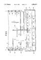
- FIG. 1is a perspective view of the material handling container of the subject invention with the walls in their upright position;
- FIG. 2is a perspective view wherein the drop door in the sidewall is folded outward and showing the smooth planer interior of the container;
- FIG. 3is a partially broken away perspective view of the container showing an end wall in its upright, erect position and a sidewall disposed between its collapsed and upright position;
- FIG. 4is a cross-sectional view taken substantially along lines 4--4 of FIG. 1;
- FIG. 5is a cross-section side view taken substantially along lines 5-5 of FIG. 1 and showing the reinforcement members of the container;
- FIG. 6is an exploded side view of the base and one sidewall of the subject invention.
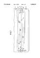
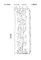
- FIG. 7is a side view of the container when the walls are in their collapsed position with another container stacked thereon;
- FIG. 8is another side view of the container when the walls are in their collapsed position with another container stacked thereon;
- FIG. 9is a perspective view of the container when the walls are in their collapsed position.
- the subject inventionis directed toward a material handling container of the type for packaging, shipping and inventorying goods and is generally shown at 10 in FIGS. 1 and 2.
- the containeris molded of a thermoplastic material and includes a base, generally indicated at 12, a pair of sidewalls 14 and a pair of end walls 16.
- Each of the walls 14, 16are hingedly connected to the base 12 and moveable between a collapsed position wherein the walls are folded one on top of the other as shown in FIG. 9 and an upright position wherein the walls extend vertically upward from the base 12 to define an interior 18 of the container 10 as shown in FIGS. 1 and 2.
- the base 12presents a bottom 20 of the container, a portion of which can be seen in FIG. 3, and which can take the form of either a solid planer sheet of plastic or a grid-like configuration wherein the interior 18 of the container 10 is exposed to the environment at the base 12.
- the bottom 20can be any combination of solid planer sheets or grid-like configuration.
- the base 12further includes a series of legs, generally indicated at 22, extending from the bottom 20 of the container.
- the series of legsincludes corner legs 24 located at each of the four corners of the container 10 and intermediate legs 26 disposed between the corner legs 24 along the perimeter of the base 12.
- Straps 28extend between the legs 22 and define channels 29 between predetermined legs 22. More specifically, the straps 28 extend between corner legs 24 and intermediate legs 26 to define a pair of channels 29 on each side of the container for receiving the forks of a forklift to facilitate the raising and lowering of a container 10.
- the base 12also includes a pair of oppositely disposed short base sides 30 extending upwardly from and integrally with the bottom 20 of the base 12 and corresponding to the sidewalls 14. Similarly, a pair of opposed base sides 32 corresponding to the end walls 16 also extend upwardly from the bottom 20 of the base.
- each of the sidewalls 14is hingedly connected through a tongue and groove type hinge, generally indicated at 34, to the upstanding sides 30 of the base 12.
- each of the end walls 16is hingedly connected through a tongue and groove type hinge, generally indicated at 36, to the upstanding sides 32 of the base 12.
- each hinge 34, 36includes tongues 38 extending from the walls 14, 16 and which are adapted to be received in corresponding grooves or sockets 40 in the base sides 30, 32.
- Both the tongues 38 and sockets 40include aligned apertures which receive a rod which forms a hinge axis about which the side and end walls rotate between collapsed and upright positions.
- At least one of the sidewalls 14includes a drop door 42 hingedly connected to the sidewall via a tongue and groove type hinge 44 in the same manner that the walls 14, 16 are hinged to the base 12.
- the drop door 42is rotatably moveable between an open position as shown in FIG. 2 and a closed position wherein the door 42 is latched to the sidewall 14 via latches 46 shown in FIG. 3 as is common in the art.
- the drop door 42further includes oval shaped tabs 47 disposed along the edges thereof which are received in corresponding sockets 49 in the sidewall 14 at the opening created by the door 42.
- the drop door 42provides access to the interior 18 of the container 10 through a sidewall 14 when the container is in its erect, upright position.
- wall latches 48are employed to latch adjacent side and end walls together when they are in their upright position.
- the container 10also includes a wall interlocking system, generally indicated at 50, located on adjacent side and end walls 14, 16 for providing interlocking engagement therebetween when the walls are in their upright position.
- the wall locking system 50includes terminal portions 52 disposed along either edge of the sidewalls 14 defining planes which are substantially parallel to the plane defined by the sidewall 14 associated with the terminal portions 52.
- the terminal portions 52include at least one, but preferable a plurality of, tabs, generally indicated at 54, disposed at predetermined spaced intervals along the terminal portions 52 and extending from the terminal portions 52 in a direction away from the interior 18 of the container 10.
- the tabs 54have arcuately shaped, conically converging surfaces 56 which define a truncated cone.
- the arcuate surfaces 56form an oval shaped tab 54 when viewed in FIG. 6.
- the oval shaped tabs 54have a longitudinal axis A which is substantially vertical and perpendicular to the bottom 20 of the base 12 when the walls 14 are in their upright position.
- the wall interlocking system 50includes a corner portion 58 which is disposed along either edge of the end walls 16. As best shown in FIGS. 1 and 4, the corner portions 58 form wrap-around edges to the container 10 and thus substantially defines a plane which is parallel to the plane defined by the adjacent sidewalls 14 when the adjacent side and end walls are in their upright position.
- the corner portions 58includes at least one, but preferably a plurality of, sockets 60 disposed at predetermined spaced intervals along the corner portion 58 and corresponding to the tabs 54.
- each of the sockets 60have arcuately shaped, conically converging, oval shaped surfaces corresponding to the tabs 54 which are adapted to receive the tabs in a snug fashion and thereby lock adjacent side and end walls 14, 16 together when the adjacent walls are in their upright position.
- the arcuately shaped conically converging surfaces of the tabs 54 and the corresponding sockets 60aid in the interlocking action of the adjacent side and end walls because there are no sharp corners or angle surfaces which require close tolerances in order to precisely interfit.
- the arcuate surfacesform continuous interlocks about the entire peripheral surfaces of the tabs 54 and sockets 60 which strengthens the corner of the container 10 when in its upright position.
- the terminal portions 52are themselves defined by a pair of marginal members 62 which are disposed in spaced parallel relationship with respect to one another and parallel to the plane defined by their associated sidewalls 14.
- a plurality of reinforcing flanges 64extend between the marginal members 62 so as to form open ended box-like sections between the marginal members 62.
- This arrangementstrengthens the terminal portions 52 while presenting a smooth planer surface on the surface 66 of the marginal member 62 facing the interior 18 of the container at the terminal portions 52 when the container is in its upright position.
- the side and end walls 14, 16present smooth planer surfaces facing the interior of the container even on the surfaces 66 of the marginal members 62 of the terminal portions 52 of the sidewalls 14.
- the container 10is adapted to receive a liner (not shown) which may be employed to inventory and ship liquid in bulk without the danger that the liner will tear, rip or otherwise leak due to contact with sharp or irregular, non-smooth surfaces facing the interior
- the hinges 34 for opposed sidewalls 14define a pair of axes 68 about which the sidewalls are rotatable between their collapsed and upright positions.
- the hinges 36 for the opposed end walls 16define a pair of axes 70 about which the end walls are rotatable between their collapsed and upright positions.
- the hinge axes 68 for the opposed sidewalls 14are disposed on a common horizontal plane bisecting these axes 68.
- sidewall hinge axes 68are on the same plane, the planes defined by the opposed sidewalls 14 intersect when in this position. However, the sidewalls 14 are isolated from any loadbearing responsibility and therefore this arrangement does not degrade the structural integrity of the container.
- the hinge axes 70 for the opposed end walls 16are also disposed on a common horizontal plane bisecting these axes 70.
- the plane bisecting the hinge axes 68is spaced vertically from and parallel to the plane bisecting the hinge axes 70.
- the end walls 16are supported as will be discussed in further detail below.
- the base sides 30 for the opposed sidewalls 14form a pair of ramping surfaces 72 which define oppositely opening arcuate angles with the sidewall hinge axes 68.
- the base sides 30also include horizontal surfaces 74 disposed between the two ramping surfaces 72 and parallel to the hinge axes 68.
- the base sides 32 for the opposed end walls 16have an upper marginal edge 76 disposed above each hinge axis 68, 70 which forms a platform surface 78 for supporting another container 10 when one container is stacked on another in the collapsed position.
- the end wall corner portion 58includes stacking surfaces 80 forming the terminal edge thereof and which are adapted to rest upon and be supported by the ramping surfaces 72 and a portion of the horizontal surface 74 at an angle to the horizontal when the container 10 is collapsed. However, only the stacking surfaces 80 of the first end wall 16 which is collapsed is supported as described above.
- the second collapsed end wall 16is supported as follows.
- the end walls 16include wall support surfaces 82 disposed in parallel spaced relationship to the stacking surfaces 80 on the opposite sides of the corner portions 58 from the stacking surfaces 80. A portion of the wall support surfaces 82 on the first collapsed end wall are employed to support the other, second collapsed end wall 16 along the second end walls stacking surface 80 when both end walls are in their collapsed position.
- the collapsible material handling container as described aboveis preferably molded of a thermoplastic resin such as high density polyethylene, or Xenoy®, Cycolac®, Cycoloy® or Lexan®, the latter four of which are engineering thermoplastics available from General Electric Company GE Plastics division.
- the container of the subject inventionis not formed using a structural foam molding process. Rather, the walls and base of the subject invention are formed via a gas assist, low pressure injection molding process using the methods and apparatuses as described for example in U.S. Pat. No. 4,824,732 issued to Watson et al. for a Process and Apparatus for Injection Moulding and Mouldings Produced Thereby; U.S. Pat.
- the resulting cross-sectional thickness of any wall or portion of the basecan be as little as 0.150 inches. This reduces the weight of the container as compared with the structural foam molding containers of the prior art, which in turn reduces the time needed to cool the part in the mold and therefore reduces the cycle time and labor needed to mold any given part of the container.
- each of the injection molded walls or basethere are portions which define a plastic planer expanse 84.
- These expansesmay be found on any portion of the container.
- the underside of the bottom 20 of the base 12 or the exterior surface of the side and end walls 14, 16all define planer expanses.
- these expansesinclude a plurality of reinforcement members, generally indicated at 86, molded integrally with the container at predetermined positions on the planer expanses 84.
- the reinforcement members 86are shown strengthening the walls 14, 16 of the container. Further, a section of the end wall 16 is shown in FIG. 5 to illustrate the relationship between any planer expanse 84 and the reinforcement member 86. However, it should be noted that the reinforcement members 86 could be located anywhere on the container and not just in connection with strengthening the walls.
- Each of the reinforcement members 86may be hollow channels or a combination of hollow channels and solid members.
- each of the reinforcement members 86define a hollow channel 88 disposed adjacent to the planer expanse 84 with at least one, but preferably a pair of, upstanding ribs 90 disposed in spaced parallel relationship with respect to one another extending upwardly from the channel 88 thereby adding strength to the planer expanse 84.
- the channel 88further includes a bottom wall 92 formed by the planer expanse 84 and a pair of upstanding flanges 94 disposed spaced from one another.
- a truss member 96extends between the flanges 94 and is spaced from the bottom wall 92 so as to essentially form the top of the channel 88.
- the flanges 94form the side of the channel and continue uninterrupted to form the spaced ribs 90. While the hollow channel 88 and reinforcement member 86 may take any geometric shape, the structure described above is such that the reinforcement member 86 is substantially H-like in cross-section as is shown in FIG. 5.
- the reinforcement member 86 of the subject inventioncan be employed to strengthen any part of the container thereby maintaining a high level of strength and stiffness in a thinner walled, lighter weight, less expensive container.
Landscapes
- Engineering & Computer Science (AREA)
- Mechanical Engineering (AREA)
- Containers Having Bodies Formed In One Piece (AREA)
- Rigid Containers With Two Or More Constituent Elements (AREA)
- Cartons (AREA)
Abstract
Description
Claims (5)
Priority Applications (5)
| Application Number | Priority Date | Filing Date | Title |
|---|---|---|---|
| US08/159,095US5586675A (en) | 1993-11-29 | 1993-11-29 | Reinforced material handling container |
| EP94308118AEP0655391B1 (en) | 1993-11-29 | 1994-11-03 | Collapsible container |
| DE69419392TDE69419392T2 (en) | 1993-11-29 | 1994-11-03 | Collapsible container |
| ES94308118TES2133155T3 (en) | 1993-11-29 | 1994-11-03 | FOLDING RECEPTACLE. |
| JP6286981AJPH07215337A (en) | 1993-11-29 | 1994-11-22 | Reinforced container for material handling |
Applications Claiming Priority (1)
| Application Number | Priority Date | Filing Date | Title |
|---|---|---|---|
| US08/159,095US5586675A (en) | 1993-11-29 | 1993-11-29 | Reinforced material handling container |
Publications (1)
| Publication Number | Publication Date |
|---|---|
| US5586675Atrue US5586675A (en) | 1996-12-24 |
Family
ID=22571067
Family Applications (1)
| Application Number | Title | Priority Date | Filing Date |
|---|---|---|---|
| US08/159,095Expired - LifetimeUS5586675A (en) | 1993-11-29 | 1993-11-29 | Reinforced material handling container |
Country Status (5)
| Country | Link |
|---|---|
| US (1) | US5586675A (en) |
| EP (1) | EP0655391B1 (en) |
| JP (1) | JPH07215337A (en) |
| DE (1) | DE69419392T2 (en) |
| ES (1) | ES2133155T3 (en) |
Cited By (40)
| Publication number | Priority date | Publication date | Assignee | Title |
|---|---|---|---|---|
| US6089523A (en)* | 1997-08-29 | 2000-07-18 | Lear Automative Dearborn, Inc. | Integral mirror bracket using gas assist |
| US20020108950A1 (en)* | 2001-02-14 | 2002-08-15 | Moorman Stephen E. | Collapsible container |
| US20030102309A1 (en)* | 1999-12-28 | 2003-06-05 | Peter Hartwall | Collapsible bulk container |
| US20040069780A1 (en)* | 2002-10-11 | 2004-04-15 | Rehrig Pacific Company | Portable storage device |
| US20040178197A1 (en)* | 2003-03-10 | 2004-09-16 | Rehrig Pacific Company | Collapsible container |
| US20040182858A1 (en)* | 2003-03-21 | 2004-09-23 | Rehrig Pacific Company | Collapsible container |
| US20040200833A1 (en)* | 2003-04-09 | 2004-10-14 | George Utz Holding Ag | Stackable transport box |
| US20040226945A1 (en)* | 2003-05-13 | 2004-11-18 | Hsu Roger S | Collapsible container |
| US20070095842A1 (en)* | 2005-11-01 | 2007-05-03 | Apps William P | Container |
| USD553858S1 (en)* | 2006-02-09 | 2007-10-30 | Odesa Gelistirilmis Polimer Yatirimlari Ve Dis Ticaret Anonim Sirketi | Foldable crate |
| US20070252255A1 (en)* | 2006-04-27 | 2007-11-01 | Atmel Corporation | Multi-component package with both top and bottom side connection pads for three-dimensional packaging |
| US20080017081A1 (en)* | 2006-07-24 | 2008-01-24 | Rehrig Pacific Company | Pallet assembly |
| US7331480B1 (en) | 2002-09-27 | 2008-02-19 | Roger Nolan | Articulated hinge apparatus and related methods |
| US20080116201A1 (en)* | 2006-11-17 | 2008-05-22 | Kyle Baltz | Container |
| US20080127608A1 (en)* | 2005-12-23 | 2008-06-05 | Marcus Eaton Williamson | Composite Box (C-B) System |
| US20080142399A1 (en)* | 2005-11-01 | 2008-06-19 | Apps William P | Container |
| US20080223533A1 (en)* | 2007-03-14 | 2008-09-18 | Lucent Technologies Inc. | Armor system for field protection and a method for making same |
| US20080302791A1 (en)* | 2007-06-11 | 2008-12-11 | Baltz Kyle L | Collapsible Container |
| US20090114647A1 (en)* | 2007-11-06 | 2009-05-07 | Apps William P | Collapsible container |
| US20090159593A1 (en)* | 2007-12-21 | 2009-06-25 | Apps William P | Collapsible container |
| US20090205169A1 (en)* | 2005-06-03 | 2009-08-20 | Roger Nolan | Container assembly and latch apparatus, and related methods |
| US7740149B2 (en) | 2002-09-27 | 2010-06-22 | Ropak Corporation | Container sidewall strengthening apparatus and methods |
| US20110084083A1 (en)* | 2009-10-09 | 2011-04-14 | Baltz Kyle L | Collapsible bin |
| US20110127275A1 (en)* | 2008-08-12 | 2011-06-02 | Georg Utz Holding Ag | Transport container |
| US20120067907A1 (en)* | 2010-09-20 | 2012-03-22 | Ifco Systems Gmbh | Crate |
| US8757412B2 (en) | 2012-01-09 | 2014-06-24 | Monoflo International, Inc. | Foldable container with access opening |
| US8820560B2 (en) | 2009-12-16 | 2014-09-02 | Orbis Corporation | Collapsible bin |
| US8915397B2 (en) | 2012-11-01 | 2014-12-23 | Orbis Corporation | Bulk container with center support between drop door and side wall |
| US8950613B2 (en) | 2011-02-16 | 2015-02-10 | Orbis Corporation | Bulk bin container with removable side wall |
| US20160264295A1 (en)* | 2013-01-17 | 2016-09-15 | Buckhorn Inc. | Collapsible nestable container |
| US9487326B2 (en) | 2013-11-26 | 2016-11-08 | Orbis Corporation | Bulk bin with panel to panel interlock features |
| US9708097B2 (en) | 2013-11-15 | 2017-07-18 | Orbis Corporation | Bulk bin with integrated shock absorber |
| US9863174B2 (en) | 2014-06-20 | 2018-01-09 | Orbis Corporation | Hinge rod trap for a collapsible bin |
| US10065763B2 (en) | 2016-09-15 | 2018-09-04 | Arena Packaging, Llc | Wall latching system |
| US10167110B2 (en) | 2010-05-27 | 2019-01-01 | Rehrig Pacific Company | Dual height collapsible container |
| US10703531B2 (en) | 2016-03-11 | 2020-07-07 | Rehrig Pacific Company | Collapsible crate with wood appearance |
| US11597557B2 (en) | 2018-10-04 | 2023-03-07 | Rehrig Pacific Company | Reconfigurable beverage crate |
| US20230076758A1 (en)* | 2021-09-03 | 2023-03-09 | A.R. Arena Products, Inc. | Intermediate bulk container systems and methods of using same |
| US12168544B2 (en) | 2021-09-16 | 2024-12-17 | Rehrig Pacific Company | Hybrid collapsible crate |
| US12330840B2 (en)* | 2019-02-04 | 2025-06-17 | Rehrig Pacific Company | Collapsible crate with retractable wall |
Families Citing this family (10)
| Publication number | Priority date | Publication date | Assignee | Title |
|---|---|---|---|---|
| EP0830291B1 (en)* | 1995-06-07 | 2009-05-06 | Orbis Corporation | Collapsible container with hinged sidewalls |
| SE521473C2 (en)* | 1999-04-30 | 2003-11-04 | Arca Systems Ab | Folding box |
| JP2002120833A (en)* | 2000-10-17 | 2002-04-23 | Gifu Plast Ind Co Ltd | Folding type conveying container |
| JP2003020035A (en)* | 2001-07-09 | 2003-01-21 | Sanko Co Ltd | Folding container |
| WO2003008275A2 (en)* | 2001-07-19 | 2003-01-30 | Arena Vm Limited | Collapsible container |
| ITVR20020071A1 (en)* | 2002-06-27 | 2003-12-29 | Simp S R L | PROCESS AND EQUIPMENT FOR GRAPE PASSING. |
| AU2003227022A1 (en)* | 2003-03-13 | 2004-09-30 | Paul Klinge Group A/S | Container |
| DE10345285A1 (en)* | 2003-09-30 | 2005-04-21 | Ralf Schneeberger | Heavy duty plastic transporting box for commercial haulage and warehouse logistics is collapsible, sealable, light and stackable, and side walls and bottom have high stability by specific ribbing |
| AU2008258125B2 (en)* | 2007-12-17 | 2013-09-26 | Gavin Jean Elvin-Jensen | A bulk container |
| HUE028875T2 (en)* | 2008-01-24 | 2017-01-30 | First4Boxes Ltd | collapsible container |
Citations (25)
| Publication number | Priority date | Publication date | Assignee | Title |
|---|---|---|---|---|
| DE441904C (en)* | 1925-03-11 | 1927-03-16 | Paul Hoffmann | Double-walled transport barrel |
| US2638138A (en)* | 1949-01-07 | 1953-05-12 | Goodyear Aircraft Corp | Fuel cell supporting enclosure |
| US3780903A (en)* | 1972-07-24 | 1973-12-25 | Nooter Corp | Corner construction for reinforcing rib on tank made from thin sheet metal |
| US3938689A (en)* | 1971-07-08 | 1976-02-17 | Munnik Nicholas Marie De | Processing tank |
| US3985258A (en)* | 1975-10-01 | 1976-10-12 | Quigley Patrick C | Knock-down plastic container for produce and the like |
| US4024978A (en)* | 1974-10-14 | 1977-05-24 | Hitachi, Ltd. | Tank for use with electric equipment |
| US4046278A (en)* | 1974-03-11 | 1977-09-06 | Fruehauf Corporation | Air cargo container |
| US4062467A (en)* | 1974-07-27 | 1977-12-13 | Friedrich Wolfgang E | Collapsible transport container |
| US4181237A (en)* | 1978-08-30 | 1980-01-01 | Chicago Bridge & Iron Company | Liquid storage tank with welded joint drain canal system and wall stiffener system |
| EP0026535A1 (en)* | 1979-09-26 | 1981-04-08 | Wavin B.V. | A plastics crate or tray |
| JPS59122999A (en)* | 1982-12-29 | 1984-07-16 | 三井造船株式会社 | Transporting container for carrying radioactive material or material contaminated thereby |
| US4498860A (en)* | 1982-08-06 | 1985-02-12 | Mouldmaking Design Centre Limited | Injection molding apparatus having a sprue holder with an inclined retractable ram |
| US4591065A (en)* | 1984-09-25 | 1986-05-27 | Foy Dennis M | Foldable container assembly |
| US4674647A (en)* | 1985-06-21 | 1987-06-23 | Xytec Plastics, Inc. | Collapsible storage bin |
| US4740150A (en)* | 1987-03-16 | 1988-04-26 | Peerless Cinpres Limited | Injection moulding apparatus |
| US4775068A (en)* | 1988-01-11 | 1988-10-04 | Xytec Plastics, Inc. | Collapsible container with removable access panel |
| US4917255A (en)* | 1989-02-24 | 1990-04-17 | J.I.T. Corporation | Collapsible container |
| US4923667A (en)* | 1987-09-25 | 1990-05-08 | Cinpres Limited | Method and apparatus for injection moulding |
| US4923079A (en)* | 1987-03-06 | 1990-05-08 | Ropak Corporation | Collapsible container |
| US4923666A (en)* | 1987-04-28 | 1990-05-08 | Cinpres Limited | Method of injection moulding |
| US4967927A (en)* | 1989-03-15 | 1990-11-06 | Xytec, Inc. | Container with latchable hinged sidewall gate |
| US5094356A (en)* | 1990-11-13 | 1992-03-10 | Buckhorn Material Handling Group, Inc. | Knock down bulk container |
| WO1992008650A1 (en)* | 1990-11-14 | 1992-05-29 | Fritz Schäfer Gesellschaft Mit Beschränkter Haftung | Plastic load carrier and tool for its production |
| US5232119A (en)* | 1990-07-16 | 1993-08-03 | Theresa M. Kauffman | Multi-walled pipes and storage tanks for toxic and corrosive fluids |
| WO1994008853A1 (en)* | 1992-10-21 | 1994-04-28 | Perstorp Ab | Container bottom with elevations made of a polymeric material, and a process for production thereof |
- 1993
- 1993-11-29USUS08/159,095patent/US5586675A/ennot_activeExpired - Lifetime
- 1994
- 1994-11-03EPEP94308118Apatent/EP0655391B1/ennot_activeExpired - Lifetime
- 1994-11-03ESES94308118Tpatent/ES2133155T3/ennot_activeExpired - Lifetime
- 1994-11-03DEDE69419392Tpatent/DE69419392T2/ennot_activeExpired - Lifetime
- 1994-11-22JPJP6286981Apatent/JPH07215337A/enactivePending
Patent Citations (27)
| Publication number | Priority date | Publication date | Assignee | Title |
|---|---|---|---|---|
| DE441904C (en)* | 1925-03-11 | 1927-03-16 | Paul Hoffmann | Double-walled transport barrel |
| US2638138A (en)* | 1949-01-07 | 1953-05-12 | Goodyear Aircraft Corp | Fuel cell supporting enclosure |
| US3938689A (en)* | 1971-07-08 | 1976-02-17 | Munnik Nicholas Marie De | Processing tank |
| US3780903A (en)* | 1972-07-24 | 1973-12-25 | Nooter Corp | Corner construction for reinforcing rib on tank made from thin sheet metal |
| US4046278A (en)* | 1974-03-11 | 1977-09-06 | Fruehauf Corporation | Air cargo container |
| US4062467A (en)* | 1974-07-27 | 1977-12-13 | Friedrich Wolfgang E | Collapsible transport container |
| US4024978A (en)* | 1974-10-14 | 1977-05-24 | Hitachi, Ltd. | Tank for use with electric equipment |
| US3985258A (en)* | 1975-10-01 | 1976-10-12 | Quigley Patrick C | Knock-down plastic container for produce and the like |
| US4181237A (en)* | 1978-08-30 | 1980-01-01 | Chicago Bridge & Iron Company | Liquid storage tank with welded joint drain canal system and wall stiffener system |
| EP0026535A1 (en)* | 1979-09-26 | 1981-04-08 | Wavin B.V. | A plastics crate or tray |
| US4498860A (en)* | 1982-08-06 | 1985-02-12 | Mouldmaking Design Centre Limited | Injection molding apparatus having a sprue holder with an inclined retractable ram |
| JPS59122999A (en)* | 1982-12-29 | 1984-07-16 | 三井造船株式会社 | Transporting container for carrying radioactive material or material contaminated thereby |
| US4591065A (en)* | 1984-09-25 | 1986-05-27 | Foy Dennis M | Foldable container assembly |
| US4674647A (en)* | 1985-06-21 | 1987-06-23 | Xytec Plastics, Inc. | Collapsible storage bin |
| US4923079A (en)* | 1987-03-06 | 1990-05-08 | Ropak Corporation | Collapsible container |
| US4740150A (en)* | 1987-03-16 | 1988-04-26 | Peerless Cinpres Limited | Injection moulding apparatus |
| US4740150B1 (en)* | 1987-03-16 | 1995-07-25 | Peerless Cinpres Ltd | Injection moulding apparatus |
| US4923666B1 (en)* | 1987-04-28 | 1995-02-14 | Cinpres Ltd | Method of injection moulding |
| US4923666A (en)* | 1987-04-28 | 1990-05-08 | Cinpres Limited | Method of injection moulding |
| US4923667A (en)* | 1987-09-25 | 1990-05-08 | Cinpres Limited | Method and apparatus for injection moulding |
| US4775068A (en)* | 1988-01-11 | 1988-10-04 | Xytec Plastics, Inc. | Collapsible container with removable access panel |
| US4917255A (en)* | 1989-02-24 | 1990-04-17 | J.I.T. Corporation | Collapsible container |
| US4967927A (en)* | 1989-03-15 | 1990-11-06 | Xytec, Inc. | Container with latchable hinged sidewall gate |
| US5232119A (en)* | 1990-07-16 | 1993-08-03 | Theresa M. Kauffman | Multi-walled pipes and storage tanks for toxic and corrosive fluids |
| US5094356A (en)* | 1990-11-13 | 1992-03-10 | Buckhorn Material Handling Group, Inc. | Knock down bulk container |
| WO1992008650A1 (en)* | 1990-11-14 | 1992-05-29 | Fritz Schäfer Gesellschaft Mit Beschränkter Haftung | Plastic load carrier and tool for its production |
| WO1994008853A1 (en)* | 1992-10-21 | 1994-04-28 | Perstorp Ab | Container bottom with elevations made of a polymeric material, and a process for production thereof |
Cited By (61)
| Publication number | Priority date | Publication date | Assignee | Title |
|---|---|---|---|---|
| US6089523A (en)* | 1997-08-29 | 2000-07-18 | Lear Automative Dearborn, Inc. | Integral mirror bracket using gas assist |
| US20030102309A1 (en)* | 1999-12-28 | 2003-06-05 | Peter Hartwall | Collapsible bulk container |
| US6955273B2 (en)* | 1999-12-28 | 2005-10-18 | Arca Systems Ab | Collapsible bulk container |
| US20020108950A1 (en)* | 2001-02-14 | 2002-08-15 | Moorman Stephen E. | Collapsible container |
| US7331480B1 (en) | 2002-09-27 | 2008-02-19 | Roger Nolan | Articulated hinge apparatus and related methods |
| US7740149B2 (en) | 2002-09-27 | 2010-06-22 | Ropak Corporation | Container sidewall strengthening apparatus and methods |
| US7828167B2 (en) | 2002-09-27 | 2010-11-09 | Roger Nolan | Articulated hinge apparatus and related methods |
| US20090152265A1 (en)* | 2002-09-27 | 2009-06-18 | Orbis Corporation | Articulated hinge apparatus and related methods |
| US7059489B2 (en) | 2002-10-11 | 2006-06-13 | Rehrig Pacific Company | Portable storage device |
| US20040069780A1 (en)* | 2002-10-11 | 2004-04-15 | Rehrig Pacific Company | Portable storage device |
| US20040178197A1 (en)* | 2003-03-10 | 2004-09-16 | Rehrig Pacific Company | Collapsible container |
| US7017766B2 (en) | 2003-03-10 | 2006-03-28 | Rehrig Pacific Company | Collapsible container with side wall latching capability |
| US7100786B2 (en) | 2003-03-21 | 2006-09-05 | Rehrig Pacific Company | Collapsible container |
| US20040182858A1 (en)* | 2003-03-21 | 2004-09-23 | Rehrig Pacific Company | Collapsible container |
| US20040200833A1 (en)* | 2003-04-09 | 2004-10-14 | George Utz Holding Ag | Stackable transport box |
| US7416092B2 (en)* | 2003-04-09 | 2008-08-26 | George Utz Holding Ag | Stackable transport box |
| US7195127B2 (en) | 2003-05-13 | 2007-03-27 | Rehrig Pacific Company | Collapsible container |
| US20040226945A1 (en)* | 2003-05-13 | 2004-11-18 | Hsu Roger S | Collapsible container |
| US9422082B2 (en) | 2005-06-03 | 2016-08-23 | Roger Nolan | Container assembly and latch apparatus, and related methods |
| US20090205169A1 (en)* | 2005-06-03 | 2009-08-20 | Roger Nolan | Container assembly and latch apparatus, and related methods |
| US20070194023A1 (en)* | 2005-11-01 | 2007-08-23 | Apps William P | Container |
| US20080142399A1 (en)* | 2005-11-01 | 2008-06-19 | Apps William P | Container |
| US7726502B2 (en) | 2005-11-01 | 2010-06-01 | Rehrig Pacific Company | Container |
| US20070095842A1 (en)* | 2005-11-01 | 2007-05-03 | Apps William P | Container |
| US20080127608A1 (en)* | 2005-12-23 | 2008-06-05 | Marcus Eaton Williamson | Composite Box (C-B) System |
| USD553858S1 (en)* | 2006-02-09 | 2007-10-30 | Odesa Gelistirilmis Polimer Yatirimlari Ve Dis Ticaret Anonim Sirketi | Foldable crate |
| US20070252255A1 (en)* | 2006-04-27 | 2007-11-01 | Atmel Corporation | Multi-component package with both top and bottom side connection pads for three-dimensional packaging |
| US20100212553A1 (en)* | 2006-07-24 | 2010-08-26 | Baltz Kyle L | Pallet assembly |
| US7748329B2 (en) | 2006-07-24 | 2010-07-06 | Rehrig Pacific Company | Pallet assembly |
| US20080017081A1 (en)* | 2006-07-24 | 2008-01-24 | Rehrig Pacific Company | Pallet assembly |
| US20080116201A1 (en)* | 2006-11-17 | 2008-05-22 | Kyle Baltz | Container |
| US20080223533A1 (en)* | 2007-03-14 | 2008-09-18 | Lucent Technologies Inc. | Armor system for field protection and a method for making same |
| US7641066B2 (en) | 2007-06-11 | 2010-01-05 | Rehrig Pacific Company | Collapsible container |
| US20080302791A1 (en)* | 2007-06-11 | 2008-12-11 | Baltz Kyle L | Collapsible Container |
| US20090114647A1 (en)* | 2007-11-06 | 2009-05-07 | Apps William P | Collapsible container |
| US7717283B2 (en) | 2007-11-06 | 2010-05-18 | Rehrig Pacific Company | Collapsible container |
| US20090159593A1 (en)* | 2007-12-21 | 2009-06-25 | Apps William P | Collapsible container |
| US20110127275A1 (en)* | 2008-08-12 | 2011-06-02 | Georg Utz Holding Ag | Transport container |
| US8844759B2 (en)* | 2008-08-12 | 2014-09-30 | Georg Utz Holding Ag | Transport container |
| US20110084083A1 (en)* | 2009-10-09 | 2011-04-14 | Baltz Kyle L | Collapsible bin |
| US9415898B2 (en) | 2009-12-16 | 2016-08-16 | Orbis Corporation | Bulk container with angled side wall to base installation |
| US8820560B2 (en) | 2009-12-16 | 2014-09-02 | Orbis Corporation | Collapsible bin |
| US10167110B2 (en) | 2010-05-27 | 2019-01-01 | Rehrig Pacific Company | Dual height collapsible container |
| US20120067907A1 (en)* | 2010-09-20 | 2012-03-22 | Ifco Systems Gmbh | Crate |
| US9469429B2 (en)* | 2010-09-20 | 2016-10-18 | Ifco Systems Gmbh | Crate |
| US8950613B2 (en) | 2011-02-16 | 2015-02-10 | Orbis Corporation | Bulk bin container with removable side wall |
| US8757412B2 (en) | 2012-01-09 | 2014-06-24 | Monoflo International, Inc. | Foldable container with access opening |
| US9296557B2 (en) | 2012-11-01 | 2016-03-29 | Orbis Corporation | Bulk container with center support between drop door and side wall |
| US8915397B2 (en) | 2012-11-01 | 2014-12-23 | Orbis Corporation | Bulk container with center support between drop door and side wall |
| US20160264295A1 (en)* | 2013-01-17 | 2016-09-15 | Buckhorn Inc. | Collapsible nestable container |
| US10053262B2 (en)* | 2013-01-17 | 2018-08-21 | Buckhorn Inc. | Collapsible nestable container |
| US9708097B2 (en) | 2013-11-15 | 2017-07-18 | Orbis Corporation | Bulk bin with integrated shock absorber |
| US9487326B2 (en) | 2013-11-26 | 2016-11-08 | Orbis Corporation | Bulk bin with panel to panel interlock features |
| US9863174B2 (en) | 2014-06-20 | 2018-01-09 | Orbis Corporation | Hinge rod trap for a collapsible bin |
| US10703531B2 (en) | 2016-03-11 | 2020-07-07 | Rehrig Pacific Company | Collapsible crate with wood appearance |
| US10065763B2 (en) | 2016-09-15 | 2018-09-04 | Arena Packaging, Llc | Wall latching system |
| US11597557B2 (en) | 2018-10-04 | 2023-03-07 | Rehrig Pacific Company | Reconfigurable beverage crate |
| US12330840B2 (en)* | 2019-02-04 | 2025-06-17 | Rehrig Pacific Company | Collapsible crate with retractable wall |
| US20230076758A1 (en)* | 2021-09-03 | 2023-03-09 | A.R. Arena Products, Inc. | Intermediate bulk container systems and methods of using same |
| US11834258B2 (en)* | 2021-09-03 | 2023-12-05 | A. R. Arena Products, Inc. | Intermediate bulk container systems and methods of using same |
| US12168544B2 (en) | 2021-09-16 | 2024-12-17 | Rehrig Pacific Company | Hybrid collapsible crate |
Also Published As
| Publication number | Publication date |
|---|---|
| EP0655391A2 (en) | 1995-05-31 |
| EP0655391A3 (en) | 1996-04-17 |
| EP0655391B1 (en) | 1999-07-07 |
| ES2133155T3 (en) | 1999-09-01 |
| DE69419392T2 (en) | 2000-01-05 |
| DE69419392D1 (en) | 1999-08-12 |
| JPH07215337A (en) | 1995-08-15 |
Similar Documents
| Publication | Publication Date | Title |
|---|---|---|
| US5586675A (en) | Reinforced material handling container | |
| US5467885A (en) | Collapsible material handling container | |
| US5398835A (en) | Collapsible material handling container having improved corner interlock | |
| EP0690003A1 (en) | Collapsible container | |
| US8770421B2 (en) | Collapsible refuse bin | |
| US4643314A (en) | Container construction | |
| US4775068A (en) | Collapsible container with removable access panel | |
| US5829595A (en) | Thin sheet thermoformed pallet sleeve | |
| US6776300B2 (en) | Collapsible container with closed, multi-paneled sidewalls | |
| US4917255A (en) | Collapsible container | |
| US4828132A (en) | Collapsible reusable containers, wall sleeves and hinges therefor | |
| JP2678244B2 (en) | Pallet containers | |
| US5788103A (en) | Container base | |
| WO1997039954A1 (en) | Collapsible container | |
| US20020148859A1 (en) | Drop box container | |
| EP3060488B1 (en) | Container apparatus | |
| HU215500B (en) | Plastic storage compartment, mainly vegetable storage compartment, with hinged tilting side walls | |
| CN1571748A (en) | Bulk container assembly | |
| JP2005503972A (en) | Assembled container for transportation and storage | |
| AU2018217285B2 (en) | Disassembleable cheese container with wrap-around interlock and increased fill volume | |
| US5562224A (en) | Multipurpose plastic container which can be folded up and is re-usable and stackable | |
| JP3298831B2 (en) | Assembling type container | |
| CA2136554C (en) | Collapsible container | |
| GB2300622A (en) | Collapsible containers | |
| WO2002074642A1 (en) | A collapsible insulated freight container |
Legal Events
| Date | Code | Title | Description |
|---|---|---|---|
| AS | Assignment | Owner name:GENERAL ELECTRIC COMPANY, NEW YORK Free format text:ASSIGNMENT OF ASSIGNORS INTEREST;ASSIGNORS:BORSBOOM, ANTONIUS HENDRIKUS;GENNARI, ANTHONY ANGELO;RUDOLPH, KENNETH GERARD;AND OTHERS;REEL/FRAME:006787/0355;SIGNING DATES FROM 19931109 TO 19931116 | |
| STCF | Information on status: patent grant | Free format text:PATENTED CASE | |
| FPAY | Fee payment | Year of fee payment:4 | |
| FPAY | Fee payment | Year of fee payment:8 | |
| FPAY | Fee payment | Year of fee payment:12 | |
| AS | Assignment | Owner name:SABIC INNOVATIVE PLASTICS IP B.V., NETHERLANDS Free format text:ASSIGNMENT OF ASSIGNORS INTEREST;ASSIGNOR:GENERAL ELECTRIC COMPANY;REEL/FRAME:021311/0259 Effective date:20070831 | |
| AS | Assignment | Owner name:CITIBANK, N.A., AS COLLATERAL AGENT, NEW YORK Free format text:SECURITY AGREEMENT;ASSIGNOR:SABIC INNOVATIVE PLASTICS IP B.V.;REEL/FRAME:021423/0001 Effective date:20080307 Owner name:CITIBANK, N.A., AS COLLATERAL AGENT,NEW YORK Free format text:SECURITY AGREEMENT;ASSIGNOR:SABIC INNOVATIVE PLASTICS IP B.V.;REEL/FRAME:021423/0001 Effective date:20080307 | |
| AS | Assignment | Owner name:SABIC INNOVATIVE PLASTICS IP B.V., NETHERLANDS Free format text:RELEASE BY SECURED PARTY;ASSIGNOR:CITIBANK, N.A.;REEL/FRAME:032459/0798 Effective date:20140312 |