US5586084A - Mud operated pulser - Google Patents
Mud operated pulserDownload PDFInfo
- Publication number
- US5586084A US5586084AUS08/359,622US35962294AUS5586084AUS 5586084 AUS5586084 AUS 5586084AUS 35962294 AUS35962294 AUS 35962294AUS 5586084 AUS5586084 AUS 5586084A
- Authority
- US
- United States
- Prior art keywords
- mud
- poppet
- orifice
- pressure
- piston
- Prior art date
- Legal status (The legal status is an assumption and is not a legal conclusion. Google has not performed a legal analysis and makes no representation as to the accuracy of the status listed.)
- Expired - Lifetime
Links
- 238000005553drillingMethods0.000claimsabstractdescription67
- 230000005540biological transmissionEffects0.000claimsdescription4
- 230000010363phase shiftEffects0.000claimsdescription2
- 230000004044responseEffects0.000claimsdescription2
- 230000015572biosynthetic processEffects0.000description16
- 239000012530fluidSubstances0.000description16
- 238000005755formation reactionMethods0.000description16
- 238000000034methodMethods0.000description13
- 238000005259measurementMethods0.000description9
- 238000012545processingMethods0.000description4
- 241000965255Pseudobranchus striatusSpecies0.000description3
- 238000005520cutting processMethods0.000description3
- 239000003129oil wellSubstances0.000description3
- 230000008569processEffects0.000description3
- 238000004891communicationMethods0.000description2
- 238000007796conventional methodMethods0.000description2
- 238000013461designMethods0.000description2
- 238000001514detection methodMethods0.000description2
- 238000012986modificationMethods0.000description2
- 230000004048modificationEffects0.000description2
- 230000011664signalingEffects0.000description2
- 238000011144upstream manufacturingMethods0.000description2
- 230000003213activating effectEffects0.000description1
- 230000000903blocking effectEffects0.000description1
- 238000012937correctionMethods0.000description1
- 230000007423decreaseEffects0.000description1
- 230000003247decreasing effectEffects0.000description1
- 230000007812deficiencyEffects0.000description1
- 238000001914filtrationMethods0.000description1
- 230000002706hydrostatic effectEffects0.000description1
- 238000009434installationMethods0.000description1
- 238000004519manufacturing processMethods0.000description1
- 230000007246mechanismEffects0.000description1
- 238000005457optimizationMethods0.000description1
- 230000000149penetrating effectEffects0.000description1
- 239000003208petroleumSubstances0.000description1
- 230000005855radiationEffects0.000description1
- 238000011084recoveryMethods0.000description1
- 239000011435rockSubstances0.000description1
- 238000010079rubber tappingMethods0.000description1
- 239000000523sampleSubstances0.000description1
- 230000007480spreadingEffects0.000description1
- 238000003892spreadingMethods0.000description1
Images


Classifications
- E—FIXED CONSTRUCTIONS
- E21—EARTH OR ROCK DRILLING; MINING
- E21B—EARTH OR ROCK DRILLING; OBTAINING OIL, GAS, WATER, SOLUBLE OR MELTABLE MATERIALS OR A SLURRY OF MINERALS FROM WELLS
- E21B47/00—Survey of boreholes or wells
- E21B47/12—Means for transmitting measuring-signals or control signals from the well to the surface, or from the surface to the well, e.g. for logging while drilling
- E21B47/14—Means for transmitting measuring-signals or control signals from the well to the surface, or from the surface to the well, e.g. for logging while drilling using acoustic waves
- E21B47/18—Means for transmitting measuring-signals or control signals from the well to the surface, or from the surface to the well, e.g. for logging while drilling using acoustic waves through the well fluid, e.g. mud pressure pulse telemetry
- G—PHYSICS
- G01—MEASURING; TESTING
- G01V—GEOPHYSICS; GRAVITATIONAL MEASUREMENTS; DETECTING MASSES OR OBJECTS; TAGS
- G01V1/00—Seismology; Seismic or acoustic prospecting or detecting
- G01V1/40—Seismology; Seismic or acoustic prospecting or detecting specially adapted for well-logging
- G01V1/52—Structural details
- Y—GENERAL TAGGING OF NEW TECHNOLOGICAL DEVELOPMENTS; GENERAL TAGGING OF CROSS-SECTIONAL TECHNOLOGIES SPANNING OVER SEVERAL SECTIONS OF THE IPC; TECHNICAL SUBJECTS COVERED BY FORMER USPC CROSS-REFERENCE ART COLLECTIONS [XRACs] AND DIGESTS
- Y10—TECHNICAL SUBJECTS COVERED BY FORMER USPC
- Y10S—TECHNICAL SUBJECTS COVERED BY FORMER USPC CROSS-REFERENCE ART COLLECTIONS [XRACs] AND DIGESTS
- Y10S367/00—Communications, electrical: acoustic wave systems and devices
- Y10S367/911—Particular well-logging apparatus
- Y10S367/912—Particular transducer
Definitions
- the present inventionrelates generally to a telemetry system for transmitting data from a downhole drilling assembly to the surface of a well during drilling operations. More particularly, the present invention relates to a pilot operated mud pulsing valve for use in a measurement while drilling (“MWD”) system or a logging while drilling (“LWD”) system to transmit downhole measurements to the surface of the well during drilling operations through the medium of the drilling fluid. Still more particularly, the present invention relates to a mud pulsing valve capable of generating multiple bits of data in a single pulse to increase the bandwidth of the mud pulse telemetry system.
- MWDmeasurement while drilling
- LWDlogging while drilling
- Such informationtypically includes characteristics of the earth formations traversed by the wellbore, in addition to data relating to the size and configuration of the borehole itself.
- the collection of information relating to conditions downholecan be performed by several methods.
- Oil well logginghas been known in the industry for many years as a technique for providing information to a driller regarding the particular earth formation being drilled.
- a probe or "sonde” housing formation sensorsis lowered into the borehole after some or all of the well has been drilled, and is used to determine certain characteristics of the formations traversed by the borehole.
- the sondeis supported by a conductive wireline, which attaches to the sonde at the upper end. Power is transmitted to the sensors and instrumentation in the sonde through the conductive wireline. Similarly, the instrumentation in the sonde communicates information to the surface by electrical signals transmitted through the wireline.
- the problem with obtaining downhole measurements via wirelineis that the drilling assembly must be removed or "tripped" from the drilled borehole before the desired borehole information can be obtained. This can be both time-consuming and extremely costly, especially in situations where a substantial portion of the well has been drilled. In this situation, thousands of feet of tubing may need to be removed and stacked on the platform (if offshore). Typically, drilling rigs are rented by the day at a substantial cost. Consequently, the cost of drilling a well is directly proportional to the time required to complete the drilling process. Removing thousands of feet of tubing to insert a wireline logging tool can be an expensive proposition.
- Drilling oil and gas wellsis carried out by means of a string of drill pipes connected together so as to form a drill string. Connected to the lower end of the drill string is a drill bit. The bit is rotated and drilling accomplished by either rotating the drill string, or by use of a downhole motor near the drill bit, or by both methods.
- Drilling fluidtermed mud
- the mudis pumped down through the drill string at high pressures and volumes (such as 3000 p.s.i. at flow rates of up to 1400 gallons per minute) to emerge through nozzles or jets in the drill bit.
- the mudthen travels back up the hole via the annulus formed between the exterior of the drill string and the wall of the borehole.
- the drilling mudis cleaned and then recirculated.
- the drilling mudis used to cool the drill bit, to carry cuttings from the base of the bore to the surface, and to balance the hydrostatic pressure in the rock formations.
- sensors or transducerstypically are located at the lower end of the drill string which, while drilling is in progress, continuously or intermittently monitor predetermined drilling parameters and formation data and transmit the information to a surface detector by some form of telemetry.
- the down hole sensors employed in MWD applicationsare positioned in a cylindrical drill collar that is positioned close to the drill bit.
- the LWD systemthen employs a system of telemetry in which the data acquired by the sensors is transmitted to a receiver located on the surface.
- telemetry systemsin the prior art which seek to transmit information regarding downhole parameters up to the surface without requiring the use of a wireline tool.
- the mud pulse systemis one of the most widely used telemetry systems for MWD applications.
- the mud pulse system of telemetrycreates acoustic signals in the drilling fluid that is circulated under pressure through the drill string during drilling operations.
- the information that is acquired by the downhole sensorsis transmitted by suitably timing the formation of pressure pulses in the mud stream.
- the informationis received and decoded by a pressure transducer and computer at the surface.
- the drilling mud pressure in the drill stringis modulated by means of a valve and control mechanism, generally termed a pulser or mud pulser.
- the pulseris usually mounted in a specially adapted drill collar positioned above the drill bit.
- the generated pressure pulsetravels up the mud column inside the drill string at the velocity of sound in the mud.
- the velocitymay vary between approximately 3000 and 5000 feet per second.
- the rate of transmission of datais relatively slow due to pulse spreading, distortion, attenuation, modulation rate limitations, and other disruptive forces, such as the ambient noise in the drill string.
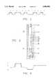
- a typical pulse rateis on the order of a pulse per second (1 Hz). As shown for example in FIG.
- the mud pulse signalis comprised of a pressure pulse at one of two amplitudes, indicating whether the mud pulser or "poppet" is open or closed. If the poppet is closed, a high pressure pulse is generated, to indicate, for example, a digital "1.” If the poppet is opened, a digital "0" is indicated.
- Mud pressure pulsescan be generated by opening and closing a valve near the bottom of the drill string so as to momentarily restrict the mud flow.
- a "negative" pressure pulseis created in the fluid by temporarily opening a valve in the drill collar so that some of the drilling fluid will bypass the bit, the open valve allowing direct communication between the high pressure fluid inside the drill string and the fluid at lower pressure returning to the surface via the exterior of the string.
- a "positive" pressure pulsecan be created by temporarily restricting the downwardly flow of drilling fluid by partially blocking the fluid path in the drillstring.
- detection of the pulses at the surfaceis sometimes difficult due to attenuation and distortion of the signal and the presence of noise generated by the mud pumps, the downhole mud motor and elsewhere in the drilling system.
- a pressure transduceris mounted directly on the line or pipe that is used to supply the drilling fluid to the drill string. An access port or tapping is formed in the pipe, and the transducer is threaded into the port.
- the transducerdetects variations in the drilling mud pressure at the surface and generates electrical signals responsive to these pressure variations.
- Both the positive and negative mud pulse systemstypically generate base band signals.
- other techniquesalso have been developed as an alternative to the positive or negative pressure pulses generated.
- One early systemis that disclosed in U.S. Pat. No. 3,309,656, which used a downhole pressure pulse generator or modulator to transmit modulated signals, carrying encoded data, at acoustic frequencies to the surface through the drilling fluid or drilling mud in the drill string.
- the downhole electrical componentsare powered by a downhole turbine generator unit, usually located downstream of the modulator unit, that is driven by the flow of drilling fluid.
- These type of devicestypically are referred to as mud sirens.
- Other examples of such devicesmay be found in U.S. Pat. Nos. 3,792,429, 4,785,300 and Re. No. 29,734.
- One problem with these mud siren type of modulatorsis the difficulty in retrieving and distinguishing the frequency modulated signals at the surface.
- None of the prior art devices to datehave been capable of providing an increased bandwidth signal in a form that provides easy delineation at the surface of the well.
- the present inventionsolves the shortcomings and deficiencies of the prior art by providing a mud pulse system that transmits mud pulse signals of varying amplitudes.
- multi-level (more than two) signalsmay be generated downhole in the pulser by providing a plurality n of parallel pressure control valves to produce n pressure amplitude levels.
- the mud pulserpreferably includes a poppet and orifice structure, which has a tendency to remain in the closed position. This tendency is obtained by providing a mud flow path bypassing the poppet and orifice, and through the interior of the piston.
- the pistonis designed with a surface area A 2 that is greater than the surface area A 1 of the poppet. As a result, the piston tends to remain in its extended position, causing the poppet valve to shut.
- the poppet valveopens by a pilot valve connected on the by-pass conduit of the piston assembly. When the pilot valve turns off, mud flow is blocked through the piston assembly, causing the piston to retract as the pressure on the poppet exceeds the pressure within the piston.
- n pressure relief valvesconnect to the by-pass conduit downstream of the piston.
- Each of the pressure relief valvesare calibrated to a particular pressure level, which causes each valve to leak mud to prevent the calibrated pressure level from being exceeded.
- Each pressure relief valvehas an associated selector valve for activating the associated pressure relief valve. Selection of a pressure relief valve causes a pressure pulse with an independent amplitude valve.
- a motor operated pressure relief valveis provided in place of the parallel pressure relief valves.
- the motor operated valvespermits incremental and continuous variations of the mud pressure. As a result, multi-level pressure amplitudes can readily be generated.
- the motor operated pressure relief valvealso permits a variety of waveforms and frequencies to be generated, thereby greatly expanding the amount of information that can be transmitted, while permitting optimization of the waveform to facilitate data recovery at the surface.
- FIG. 1illustrates a waveform generated by various prior art mud pulse telemetry systems
- FIG. 2is a schematic view of a drilling assembly implementing a mud siren modulator assembly as part of a measurement while drilling (or "MWD") system in accordance with the present invention
- FIG. 3is a schematic view of a poppet valve assembly constructed in accordance with the basic principles of the present invention.
- FIG. 4is a schematic view of an exemplary multi-level poppet valve assembly constructed in accordance with the preferred embodiment
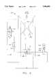
- FIG. 5is a schematic view of a multi-level poppet valve assembly constructed according to an alternative embodiment with a motor operated pressure relief control valve
- FIG. 6illustrates a waveform generated by an exemplary multi-level poppet valve assembly constructed in accordance with the embodiment of FIG. 4.
- upstream and downstreamare used to denote the relative position of certain components with respect to the direction of flow of the drilling mud.
- upstreamfrom another, it is intended to mean that drilling mud flows first through the first component before flowing through the second component.
- the terms such as “above,” “upper” and “below”are used to identify the relative position of components in the bottom hole assembly, with respect to the distance to the surface of the well, measured along the borehole path.
- a typical drilling installationwhich includes a drilling rig 10, constructed at the surface 12 of the well, supporting a drill string 14.
- the drill string 14penetrates through a rotary table 16 and into a borehole 18 that is being drilled through earth formations 20.
- the drill string 14includes a kelly 22 at its upper end, drill pipe 24 coupled to the kelly 22, and a bottom hole assembly 26 (commonly referred to as a "BHA") coupled to the lower end of the drill pipe 24.
- the BHA 26typically includes drill collars 28, a MWD tool 30, and a drill bit 32 for penetrating through earth formations to create the borehole 18.
- the kelly 22, the drill pipe 24 and the BHA 26are rotated by the rotary table 16.
- the BHA 26may also be rotated, as will be understood by one skilled in the art, by a downhole motor.
- the drill collarsare used, in accordance with conventional techniques, to add weight to the drill bit 32 and to stiffen the BHA 26, thereby enabling the BHA 26 to transmit weight to the drill bit 32 without buckling.
- the weight applied through the drill collars to the bit 32permits the drill bit to crush and make cuttings in the underground formations.
- the BHA 26preferably includes a measurement while drilling system (referred to herein as "MWD") tool 30, which may be considered part of the drill collar section 28.
- MWDmeasurement while drilling system
- drilling mudsubstantial quantities of drilling fluid (commonly referred to as “drilling mud”) are pumped from a mud pit 34 at the surface through the kelly hose 37, into the drill pipe, to the drill bit 32.
- the drilling mudis discharged from the drill bit 32 and functions to cool and lubricate the drill bit, and to carry away earth cuttings made by the bit.
- the drilling fluidrises back to the surface through the annular area between the drill pipe 24 and the borehole 18, where it is collected and returned to the mud pit 34 for filtering.
- the circulating column of drilling mud flowing through the drill stringalso functions as a medium for transmitting pressure pulse wave signals, carrying information from the MWD tool 30 to the surface.
- a downhole data signalling unit 35is provided as part of the MWD tool 30 which includes transducers mounted on the tool that take the form of one or more condition responsive sensors 39 and 41, which are coupled to appropriate data encoding circuitry, such as an encoder 38, which sequentially produces encoded digital data electrical signals representative of the measurements obtained by sensors 39 and 41. While two sensors are shown, one skilled in the art will understand that a smaller or larger number of sensors may be used without departing from the principles of the present invention.
- the sensorsare selected and adapted as required for the particular drilling operation, to measure such downhole parameters as the downhole pressure, the temperature, the resistivity or conductivity of the drilling mud or earth formations, and the density and porosity of the earth formations, as well as to measure various other downhole conditions according to known techniques. See generally "State of the Art in MWD,” International MWD Society (Jan. 19, 1993).
- the MWD tool 30preferably is located as close to the bit 32 as practical. Signals representing measurements of borehole dimensions and drilling parameters are generated and stored in the MWD tool 30.
- the data signalling unit 35preferably includes a transmitter assembly 100 to selectively interrupt or obstruct the flow of drilling mud through the drill string 14, to thereby produce encoded pressure pulses in the form of acoustic wave signals.
- the transmitter assembly 100is selectively operated in response to the data encoded electrical output of the encoder 38 to generate a corresponding encoded wave signal.
- This encoded signalis transmitted to the well surface through the medium of the drilling mud flowing in the drill string, as a series of pressure pulse signals, which preferably are encoded representations of measurement data indicative of the downhole drilling parameters and formation characteristics measured by sensors 39 and 41.
- the presence or absence of a pressure pulse in a particular interval or transmission bitpreferably is used to indicate a binary "0" or a binary "1” in accordance with conventional techniques.
- these pressure pulse signalsare received at the surface, they are detected, decoded and converted into meaningful data by a conventional acoustic signal transducer (not shown).
- the transmitter assembly 100 constructed in accordance with the principles of the present inventionincludes a mud pulse valve 200 for modulating signals in the form of pressure waves in the mud.
- the mud pulse valve 200 shown in FIG. 3is an improved poppet valve assembly, but only is capable of generating a two level mud pulse signal.
- the improved design of FIG. 3, however,facilitates the implementation of the multi-level mud pulser, which results from the preferred embodiment of FIG. 4.
- the mud pulse valve 200preferably comprises a generally cylindrical housing 205 containing a poppet 250, an orifice 225, and a conduit 235 providing a by-pass around the poppet 250 and orifice 225.
- drilling mudflows through the mud pulse valve 200 by flowing through the orifice 225.
- the flow of mudmay be obstructed by the poppet 250.
- the orifice 225preferably provides a restricted passage for the drilling mud through the mud pulse valve 200.
- the upper portion of the poppethas a surface area, designated as A 1 .
- a 1the force F 1 exerted by the mud is based upon the mud pressure P B and the surface area A 1 of the poppet 250:
- the poppetalso includes a shaft portion 252 that connects to a piston assembly 260, for controlling the position of the poppet 250 with respect to the orifice 225.
- the piston assembly 260preferably comprises a generally cylindrical housing 263, with a spring 267 mounted within the interior of said housing, outwardly biasing a piston 265.
- the springhas a predetermined bias force represented as F K .
- the housingincludes an inlet port 266 and an outlet port 269 forming part of the conduit by pass path 235.
- the interior surface of piston 265has a surface area A 2 .
- the force F 2 exerted by the mud pressure P C on the interior surface of piston 265is found as follows:
- the conduit 235provides a mud flow path through a pilot valve 270, orifice 280, piston assembly 260, and either through a pressure control valve 290 or orifice 285.
- the conduit 235provides a by-pass path around orifice 225 and poppet 250.
- the pilot valve 270functions to enable and disable mud flow through conduit 235.
- the pilot valve 270preferably includes a solenoid 273 which connects electrically to a telemetry control module (not shown). Signals received from the telemetry control module energize and deenergize solenoid 273, opening and closing pilot valve 270.
- Orifice 280represents one or more flow restrictions in the conduit 235.
- the orifice 280preferably functions to limit the flow of drilling mud through the conduit 235, so that the primary flow path is through the orifice 225 and poppet 250 structure.
- the conduit 235also includes a flow path through the interior of the piston assembly 260 to provide a force F 2 tending to bias the poppet 250 to a closed position with respect to orifice 225.
- the conduit pathincludes a pressure relief control valve 290 connected on the outlet port of the piston assembly 260.
- the pressure relief control valve 290is set to a desired pressure, with the result that mud will leak through the pressure relief valve 290 when the pressure in the conduit 235 exceeds the preset value of the relief valve 290.
- An orifice 285is included as an alternative path around relief valve 290, to permit the mud to bleed out of the piston assembly 260. As one skilled in the art will understand, the orifice 285 represents a flow restricted path to permit pressure to increase as required in conduit 235.
- pilot valveturns off, as would occur if the telemetry control module indicates that a digital "0" is to be transmitted, then mud flow is stopped through conduit 235.
- the mud pressure within the piston assembly 260then drops, as mud bleeds out through orifice 285.
- the poppetis forced open, dropping the pressure at point B.
- the pilot valve 270is reopened by a signal from the telemetry control module, causing the poppet 250 to shut and increasing the pressure at point B.
- the mud pulse valve 300 constructed in accordance with the preferred embodiment of FIG. 4generally comprises an orifice 325, a popper 350, and a conduit path 335 through a pilot valve 370, a piston assembly 360 and a multiple pressure relief control valve section 390.
- drilling mudtypically flows through the mud pulse valve 300 by flowing through the orifice 325. Mud flow is partially or totally obstructed by the poppet 350.
- the upper portion of the poppet 350has a surface area, designated as A 1 .
- the force F 1 on the poppet 350 from the mud flowis determined by the mud pressure and the surface area of the poppet 350 according to equation (1), above.
- the poppet 350includes a shaft portion 352 that connects to a piston assembly 360, for controlling the position of the poppet 350 with respect to the orifice 325.
- the piston assembly 360preferably comprises a generally cylindrical housing 363, with a spring 367 mounted within the interior of said housing, outwardly biasing a piston 365.
- the housingincludes an inlet port 366 and an outlet port 369 forming part of the conduit by-pass path 335.
- the interior surface of piston 365has a surface area A 2 .
- the force generated by the mud pressure within the piston 365is found in accordance with equation (2), above.
- the conduit 335defines a mud flow path through pilot valve 370, orifice 380, piston assembly 360, and pressure control valve section 390.
- the conduit 335provides a by-pass path around orifice 325 and poppet 350.
- the conduit 335also includes a section 338 to provide a mud flow path from the piston assembly 360 to a point downstream of the poppet 350.
- the pilot valve 370preferably comprises a three-way valve that includes a solenoid 373 connecting electrically to a telemetry control module (not shown). Signals received from the telemetry control module energize and deenergize solenoid 373, opening and closing pilot valve 370.
- a flow pathis provided between point 1 and point 2, enabling mud flow into piston assembly 360.
- pilot valve 370closes, a flow path is provided between point 2 and point 3, thus permitting mud to flow out of piston assembly 360 and back into the drillstring.
- Orifice 380represents one or more flow restrictions in the conduit 335.
- the orifice 380functions to limit the flow of drilling mud through the conduit 335, so that the primary flow path is through the orifice 325 and poppet 350 structure.
- the conduit 335also includes a flow path through the interior of the piston assembly 360 to provide a force tending to bias the poppet 350 to a closed position with respect to orifice 325.
- the conduit pathincludes a pressure relief control valve section 390 connected to the outlet port 369 of the piston assembly 360.
- the pressure relief control valve section 390preferably comprises three or more pressure relief control valves to provide a multi-level mud pulse signal for transmission to the surface of the well.
- four pressure relief valves 391, 392, 393, 394are provided.
- Each of the pressure relief valvespreferably is set to a different pressure to represent the different amplitude values to be generated by the mud pulse valve 300.
- Each of the pressure relief valves 391, 392, 393, 394has an associated selector valve 301, 302, 303, 304, respectively, for permitting mud flow to the associated pressure relief valve.
- the selector valves 301, 302, 303, 304each have a solenoid section 311, 312, 313, 314 for opening and closing the associated selector valve 301, 302, 303, 304.
- Each of the solenoids 311, 312, 313, 314connect electrically to a telemetry control unit for receiving signals that indicate which selector switch to turn on to produce the desired pulse amplitude.
- a pressure pulseis generated by selecting one of the pressure relief control valves 391, 392, 393, 394 by opening one of the selector valves 301, 302, 303, 304. If the pressure in the conduit 335 becomes greater than the selected pressure relief control valve, then mud flows through the selected relief valve to maintain the pressure in conduit 335 below the preset value of the selected valve. Limiting the pressure within the piston assembly 360 (point C) to a predefined pressure keeps the poppet 350 from closing, thereby permitting mud flow through the orifice 325. In the preferred embodiment, therefore, poppet 350 functions to partially block mud flow through the orifice. The amount that the poppet 350 blocks mud flow through the orifice 325 is determined by which pressure relief control valve is selected.
- pressure relief valve 394only a certain pressure would be permitted within the piston assembly 360 to obtain a pressure at point B of, for example, 50 psi, which might indicate a value of "1".
- pressure relief valve 393a greater pressure would be permitted within the piston assembly 360 to obtain a pressure at point B of, for example, 100 psi, which might indicate a value of "2".
- Selection of pressure relief valve 392might produce a pressure at point B of 150 psi (for a value of "3"), while pressure relief valve 391 would result in a pressure of 200 psi, for a value of "4".
- pilot valve 370turns off, as would occur if the telemetry control module indicates that a "0" value is to be transmitted, then mud flow is stopped through conduit 335. The mud pressure within the piston assembly 360 then drops, as mud bleeds out through the pilot valve 370 into path 338. As the pressure within the piston assembly 360 (point C) falls, the poppet 350 is forced fully open, dropping the pressure at point B to its minimum possible value.
- FIG. 6an example of a mud pulse waveform that can be generated with a four level mud pulser valve is depicted.
- the mud pulser in this examplegenerates mud pressure pulses capable of denoting a level "0", a level "1", a level "2" and a level "3".
- four different signalscan be transmitted during any pulse period.
- Other communication techniquesmay also be employed by one skilled in the art to further enhance the bandwidth of the signal.
- FIG. 5an alternative embodiment for a mud pulse valve 400 is shown for obtaining multi-level mud pulse signals.
- the multiple pressure relief control valve section (390 of FIG. 4)is replaced with a motor operated pressure control valve 490.
- the other components of FIG. 5may be identical to those shown in FIG. 4, and thus the same reference numerals have been used to denoted those components.
- the motor operated pressure control valve 490connects to a motor 450.
- the motor 450preferably comprises a variable torque motor, which is capable of varying the pressure setting of control valve 490.
- the pressure setting of valve 490preferably is controlled by a spring 475, so that as the motor torque increases, so does the force applied by motor 450 to the spring 475.
- the force on spring 475is applied to valve 490, causing the pressure setting of the control valve 490 to increase.
- the torque at which the variable torque motor 450 operatespreferably is determined by processing circuitry in the telemetry control module.
- a feedback signal from the mud pulser valve 400is provided to the processing circuitry to enable the processing circuitry to precisely regulate the pressure setting of control valve 400.
- the feedback signalmay indicate the pressure differential between points B, C, D, or may indicate the movement of spring 475.
- Other feedback signalsalso could be provided, as will be apparent to one skilled in the art.
- mud pulse valve 400By varying the setting of the pressure control valve 490, it is possible for mud pulse valve 400 to generate a varying amplitude signal, with a large number of available levels for transmitting information.
- the embodiment of FIG. 5enables the pulser valve 400 to generate a variety of mud pulse signals of varying heights or forms to be transmitted to the surface to optimize signal recognition and data rates.
- the mud pulse valve 400could be used to generate passband telemetry signals like frequency shift keyed (FSK) signals, phase shift keyed (PSK) signals and quadrature amplitude modulation (QAM) signals.
- FSKfrequency shift keyed
- PSKphase shift keyed
- QAMquadrature amplitude modulation
Landscapes
- Physics & Mathematics (AREA)
- Life Sciences & Earth Sciences (AREA)
- Engineering & Computer Science (AREA)
- Geology (AREA)
- Environmental & Geological Engineering (AREA)
- Geophysics (AREA)
- Remote Sensing (AREA)
- Acoustics & Sound (AREA)
- Mining & Mineral Resources (AREA)
- General Life Sciences & Earth Sciences (AREA)
- Fluid Mechanics (AREA)
- Geochemistry & Mineralogy (AREA)
- General Physics & Mathematics (AREA)
- Earth Drilling (AREA)
Abstract
Description
F.sub.1 =P.sub.B ×A.sub.1 (1)
F.sub.2 =P.sub.c ×A.sub.2 (2)
Claims (32)
Priority Applications (1)
| Application Number | Priority Date | Filing Date | Title |
|---|---|---|---|
| US08/359,622US5586084A (en) | 1994-12-20 | 1994-12-20 | Mud operated pulser |
Applications Claiming Priority (1)
| Application Number | Priority Date | Filing Date | Title |
|---|---|---|---|
| US08/359,622US5586084A (en) | 1994-12-20 | 1994-12-20 | Mud operated pulser |
Publications (1)
| Publication Number | Publication Date |
|---|---|
| US5586084Atrue US5586084A (en) | 1996-12-17 |
Family
ID=23414631
Family Applications (1)
| Application Number | Title | Priority Date | Filing Date |
|---|---|---|---|
| US08/359,622Expired - LifetimeUS5586084A (en) | 1994-12-20 | 1994-12-20 | Mud operated pulser |
Country Status (1)
| Country | Link |
|---|---|
| US (1) | US5586084A (en) |
Cited By (80)
| Publication number | Priority date | Publication date | Assignee | Title |
|---|---|---|---|---|
| EP0911483A2 (en) | 1997-10-27 | 1999-04-28 | Halliburton Energy Services, Inc. | Well system including composite pipes and a downhole propulsion system |
| US5899958A (en)* | 1995-09-11 | 1999-05-04 | Halliburton Energy Services, Inc. | Logging while drilling borehole imaging and dipmeter device |
| US6002643A (en)* | 1997-08-19 | 1999-12-14 | Computalog Limited | Pulser |
| US6016288A (en)* | 1994-12-05 | 2000-01-18 | Thomas Tools, Inc. | Servo-driven mud pulser |
| WO2001094750A1 (en)* | 2000-06-05 | 2001-12-13 | Schlumberger Technology Corporation | Method and apparatus for downhole fluid pressure signal generation and transmission |
| US6469637B1 (en) | 1999-08-12 | 2002-10-22 | Baker Hughes Incorporated | Adjustable shear valve mud pulser and controls therefor |
| US20020159333A1 (en)* | 2001-03-13 | 2002-10-31 | Baker Hughes Incorporated | Hydraulically balanced reciprocating pulser valve for mud pulse telemetry |
| US6510867B2 (en)* | 1999-09-03 | 2003-01-28 | Lafleur Petroleum Services, Inc. | Pressure relief valve |
| US20030043694A1 (en)* | 2001-09-04 | 2003-03-06 | Collette Herman D. | Frequency regulation of an oscillator for use in MWD transmission |
| US20030056985A1 (en)* | 2001-02-27 | 2003-03-27 | Baker Hughes Incorporated | Oscillating shear valve for mud pulse telemetry |
| US6555926B2 (en)* | 2001-09-28 | 2003-04-29 | Baker Hughes Incorporated | Pulser |
| WO2003069120A2 (en) | 2002-02-13 | 2003-08-21 | Halliburton Energy Services, Inc. | Dual channel downhole telemetry |
| US20030166470A1 (en)* | 2002-03-01 | 2003-09-04 | Michael Fripp | Valve and position control using magnetorheological fluids |
| US6714138B1 (en) | 2000-09-29 | 2004-03-30 | Aps Technology, Inc. | Method and apparatus for transmitting information to the surface from a drill string down hole in a well |
| US20040069530A1 (en)* | 2001-01-24 | 2004-04-15 | Kenneth Prain | Pressure pulse generator |
| US6843332B2 (en) | 1997-10-27 | 2005-01-18 | Halliburton Energy Services, Inc. | Three dimensional steerable system and method for steering bit to drill borehole |
| US20050028522A1 (en)* | 2003-08-05 | 2005-02-10 | Halliburton Energy Services, Inc. | Magnetorheological fluid controlled mud pulser |
| US6923273B2 (en) | 1997-10-27 | 2005-08-02 | Halliburton Energy Services, Inc. | Well system |
| US20050199392A1 (en)* | 2004-03-09 | 2005-09-15 | Connell Michael L. | Method and apparatus for positioning a downhole tool |
| US20050231383A1 (en)* | 2004-04-06 | 2005-10-20 | Pratt F D | Intelligent efficient servo-actuator for a downhole pulser |
| US20050260089A1 (en)* | 2001-03-13 | 2005-11-24 | Baker Hughes Incorporated | Reciprocating pulser for mud pulse telemetry |
| US20060034154A1 (en)* | 2004-07-09 | 2006-02-16 | Perry Carl A | Rotary pulser for transmitting information to the surface from a drill string down hole in a well |
| US20060131014A1 (en)* | 2004-12-22 | 2006-06-22 | Schlumberger Technology Corporation | Borehole communication and measurement system |
| US20060164918A1 (en)* | 2005-01-13 | 2006-07-27 | Halliburton Energy Services, Inc. | Methods and systems for transmitting and receiving a discrete multi-tone modulated signal in a fluid |
| US20060260806A1 (en)* | 2005-05-23 | 2006-11-23 | Schlumberger Technology Corporation | Method and system for wellbore communication |
| US20070017671A1 (en)* | 2005-07-05 | 2007-01-25 | Schlumberger Technology Corporation | Wellbore telemetry system and method |
| US20070023718A1 (en)* | 2005-07-29 | 2007-02-01 | Precision Energy Services, Ltd. | Mud pulser |
| US20070052550A1 (en)* | 2005-09-06 | 2007-03-08 | Collette Herman D | Hydraulic Oscillator For Use in a Transmitter Valve |
| US20070056771A1 (en)* | 2005-09-12 | 2007-03-15 | Manoj Gopalan | Measurement while drilling apparatus and method of using the same |
| US20070258327A1 (en)* | 2006-04-19 | 2007-11-08 | Harvey Peter R | Measurement while drilling tool and method |
| US20070263488A1 (en)* | 2006-05-10 | 2007-11-15 | Schlumberger Technology Corporation | Wellbore telemetry and noise cancellation systems and method for the same |
| US20070296606A1 (en)* | 2004-10-12 | 2007-12-27 | Oyvind Godager | System and Method for Wireless Data Transmission |
| US20080002525A1 (en)* | 2006-06-30 | 2008-01-03 | Pratt F Dale | Rotary pulser |
| US20080204270A1 (en)* | 2007-02-23 | 2008-08-28 | Precision Energy Services, Ltd. | Measurement-while-drilling mud pulse telemetry reflection cancelation |
| US20090067288A1 (en)* | 2004-10-12 | 2009-03-12 | Well Technology As | System and Method for Wireless Communication in a Producing Well System |
| US20090285054A1 (en)* | 2008-05-19 | 2009-11-19 | Haoshi Song | Downhole Telemetry System and Method |
| US20100110833A1 (en)* | 2006-07-26 | 2010-05-06 | Close David | Pressure release encoding system for communicating downhole information through a wellbore to a surface location |
| US20100201540A1 (en)* | 2006-05-10 | 2010-08-12 | Qiming Li | System and method for using dual telemetry |
| EP2240668A2 (en)* | 2007-09-07 | 2010-10-20 | Allen Young | Mud pulse telemetry system |
| US20110048806A1 (en)* | 2009-08-25 | 2011-03-03 | Baker Hughes Incorporated | Apparatus and Methods for Controlling Bottomhole Assembly Temperature During a Pause in Drilling Boreholes |
| US20110149692A1 (en)* | 2008-08-23 | 2011-06-23 | Collette Herman D | Method of Communication Using Improved Multi-Frequency Hydraulic Oscillator |
| US20110169655A1 (en)* | 2010-01-11 | 2011-07-14 | Welltronics Applications, Llc | Method for a pressure release encoding system for communicating downhole information through a wellbore to a surface location |
| US20120148417A1 (en)* | 2010-12-09 | 2012-06-14 | Remi Hutin | Active compensation for mud telemetry modulator and turbine |
| CN101294492B (en)* | 2007-04-29 | 2012-08-22 | 西部钻探克拉玛依钻井工艺研究院 | Slurry pulsator |
| US8474548B1 (en) | 2005-09-12 | 2013-07-02 | Teledrift Company | Measurement while drilling apparatus and method of using the same |
| WO2013101945A1 (en)* | 2011-12-28 | 2013-07-04 | Tempress Technologies, Inc. | Split ring shift control for hydraulic pulse valve |
| CN103236845A (en)* | 2013-04-18 | 2013-08-07 | 西安石油大学 | Method for compacting data transmitted with drilling well mud pulse |
| US8514657B2 (en) | 2009-07-23 | 2013-08-20 | Halliburton Energy Services, Inc. | Generating fluid telemetry |
| WO2013124645A1 (en)* | 2012-02-21 | 2013-08-29 | Tendeka B.V. | Wireless communication |
| US20130222149A1 (en)* | 2012-02-24 | 2013-08-29 | Schlumberger Technology Corporation | Mud Pulse Telemetry Mechanism Using Power Generation Turbines |
| US8528219B2 (en) | 2009-08-17 | 2013-09-10 | Magnum Drilling Services, Inc. | Inclination measurement devices and methods of use |
| US20130286787A1 (en)* | 2012-04-25 | 2013-10-31 | Tempress Technologies, Inc. | Low-Frequency Seismic-While-Drilling Source |
| US8881414B2 (en) | 2009-08-17 | 2014-11-11 | Magnum Drilling Services, Inc. | Inclination measurement devices and methods of use |
| US9000939B2 (en) | 2011-09-27 | 2015-04-07 | Halliburton Energy Services, Inc. | Mud powered inertia drive oscillating pulser |
| WO2015102571A1 (en)* | 2013-12-30 | 2015-07-09 | Halliburton Energy Services, Inc. | Borehole fluid-pulse telemetry apparatus and method |
| US9238965B2 (en) | 2012-03-22 | 2016-01-19 | Aps Technology, Inc. | Rotary pulser and method for transmitting information to the surface from a drill string down hole in a well |
| WO2016061179A1 (en)* | 2014-10-16 | 2016-04-21 | Reme, L.L.C. | Smart lower end |
| US9422809B2 (en) | 2012-11-06 | 2016-08-23 | Evolution Engineering Inc. | Fluid pressure pulse generator and method of using same |
| US9453410B2 (en) | 2013-06-21 | 2016-09-27 | Evolution Engineering Inc. | Mud hammer |
| CN106224309A (en)* | 2016-08-31 | 2016-12-14 | 中国船舶重工集团公司第七八研究所 | A kind of oil-filled hydraulic system of piston type mud pulse generator |
| US9540926B2 (en) | 2015-02-23 | 2017-01-10 | Aps Technology, Inc. | Mud-pulse telemetry system including a pulser for transmitting information along a drill string |
| US9574441B2 (en) | 2012-12-17 | 2017-02-21 | Evolution Engineering Inc. | Downhole telemetry signal modulation using pressure pulses of multiple pulse heights |
| US9631487B2 (en) | 2014-06-27 | 2017-04-25 | Evolution Engineering Inc. | Fluid pressure pulse generator for a downhole telemetry tool |
| US9631488B2 (en) | 2014-06-27 | 2017-04-25 | Evolution Engineering Inc. | Fluid pressure pulse generator for a downhole telemetry tool |
| US9670774B2 (en) | 2014-06-27 | 2017-06-06 | Evolution Engineering Inc. | Fluid pressure pulse generator for a downhole telemetry tool |
| US9714569B2 (en) | 2012-12-17 | 2017-07-25 | Evolution Engineering Inc. | Mud pulse telemetry apparatus with a pressure transducer and method of operating same |
| US9828853B2 (en) | 2012-09-12 | 2017-11-28 | Halliburton Energy Services, Inc. | Apparatus and method for drilling fluid telemetry |
| US9863197B2 (en) | 2016-06-06 | 2018-01-09 | Bench Tree Group, Llc | Downhole valve spanning a tool joint and methods of making and using same |
| US10323511B2 (en) | 2017-02-15 | 2019-06-18 | Aps Technology, Inc. | Dual rotor pulser for transmitting information in a drilling system |
| WO2019139870A1 (en)* | 2018-01-09 | 2019-07-18 | Rime Downhole Technologies, Llc | Hydraulically assisted pulser system and related methods |
| US10465506B2 (en) | 2016-11-07 | 2019-11-05 | Aps Technology, Inc. | Mud-pulse telemetry system including a pulser for transmitting information along a drill string |
| US10753201B2 (en) | 2012-12-17 | 2020-08-25 | Evolution Engineering Inc. | Mud pulse telemetry apparatus with a pressure transducer and method of operating same |
| WO2021003333A1 (en)* | 2019-07-03 | 2021-01-07 | Baker Hughes Oilfield Operations Llc | Force balanced reciprocating valve |
| US10934836B2 (en) | 2018-10-01 | 2021-03-02 | Doublebarrel Downhole Technologies Llc | Verifiable downlinking method |
| US11098580B2 (en) | 2019-07-10 | 2021-08-24 | Bench Tree Group, Llc | Mud pulse valve |
| CN114396256A (en)* | 2021-12-30 | 2022-04-26 | 成都三一能源环保技术有限公司 | Drilling guide command pulse signal downloading execution device and system |
| CN114526062A (en)* | 2020-11-04 | 2022-05-24 | 中石化石油工程技术服务有限公司 | Downlink communication device |
| CN115788409A (en)* | 2022-11-17 | 2023-03-14 | 抚顺中煤科工检测中心有限公司 | Coal mine directional drilling inclinometer based on wireless electromagnetic wave transmission |
| WO2023069899A1 (en)* | 2021-10-20 | 2023-04-27 | Baker Hughes Oilfield Operations Llc | Autonomous flow control device with pilot amplified operations, method, and system |
| CN116025342A (en)* | 2022-12-20 | 2023-04-28 | 上海神开石油测控技术有限公司 | A motor-type mud pulse generator with a slow release device |
Citations (6)
| Publication number | Priority date | Publication date | Assignee | Title |
|---|---|---|---|---|
| US3958217A (en)* | 1974-05-10 | 1976-05-18 | Teleco Inc. | Pilot operated mud-pulse valve |
| US4686658A (en)* | 1984-09-24 | 1987-08-11 | Nl Industries, Inc. | Self-adjusting valve actuator |
| US4742498A (en)* | 1986-10-08 | 1988-05-03 | Eastman Christensen Company | Pilot operated mud pulse valve and method of operating the same |
| US4771408A (en)* | 1986-03-31 | 1988-09-13 | Eastman Christensen | Universal mud pulse telemetry system |
| US5073877A (en)* | 1986-05-19 | 1991-12-17 | Schlumberger Canada Limited | Signal pressure pulse generator |
| US5333686A (en)* | 1993-06-08 | 1994-08-02 | Tensor, Inc. | Measuring while drilling system |
- 1994
- 1994-12-20USUS08/359,622patent/US5586084A/ennot_activeExpired - Lifetime
Patent Citations (6)
| Publication number | Priority date | Publication date | Assignee | Title |
|---|---|---|---|---|
| US3958217A (en)* | 1974-05-10 | 1976-05-18 | Teleco Inc. | Pilot operated mud-pulse valve |
| US4686658A (en)* | 1984-09-24 | 1987-08-11 | Nl Industries, Inc. | Self-adjusting valve actuator |
| US4771408A (en)* | 1986-03-31 | 1988-09-13 | Eastman Christensen | Universal mud pulse telemetry system |
| US5073877A (en)* | 1986-05-19 | 1991-12-17 | Schlumberger Canada Limited | Signal pressure pulse generator |
| US4742498A (en)* | 1986-10-08 | 1988-05-03 | Eastman Christensen Company | Pilot operated mud pulse valve and method of operating the same |
| US5333686A (en)* | 1993-06-08 | 1994-08-02 | Tensor, Inc. | Measuring while drilling system |
Cited By (162)
| Publication number | Priority date | Publication date | Assignee | Title |
|---|---|---|---|---|
| US6016288A (en)* | 1994-12-05 | 2000-01-18 | Thomas Tools, Inc. | Servo-driven mud pulser |
| US5899958A (en)* | 1995-09-11 | 1999-05-04 | Halliburton Energy Services, Inc. | Logging while drilling borehole imaging and dipmeter device |
| US6002643A (en)* | 1997-08-19 | 1999-12-14 | Computalog Limited | Pulser |
| US6843332B2 (en) | 1997-10-27 | 2005-01-18 | Halliburton Energy Services, Inc. | Three dimensional steerable system and method for steering bit to drill borehole |
| US6296066B1 (en) | 1997-10-27 | 2001-10-02 | Halliburton Energy Services, Inc. | Well system |
| US7172038B2 (en) | 1997-10-27 | 2007-02-06 | Halliburton Energy Services, Inc. | Well system |
| EP0911483A2 (en) | 1997-10-27 | 1999-04-28 | Halliburton Energy Services, Inc. | Well system including composite pipes and a downhole propulsion system |
| US6923273B2 (en) | 1997-10-27 | 2005-08-02 | Halliburton Energy Services, Inc. | Well system |
| US20050098350A1 (en)* | 1997-10-27 | 2005-05-12 | Halliburton Energy Services, Inc. | Three dimensional steering system and method for steering bit to drill borehole |
| US6863137B2 (en) | 1997-10-27 | 2005-03-08 | Halliburton Energy Services, Inc. | Well system |
| US7195083B2 (en) | 1997-10-27 | 2007-03-27 | Halliburton Energy Services, Inc | Three dimensional steering system and method for steering bit to drill borehole |
| USRE40944E1 (en) | 1999-08-12 | 2009-10-27 | Baker Hughes Incorporated | Adjustable shear valve mud pulser and controls therefor |
| US6469637B1 (en) | 1999-08-12 | 2002-10-22 | Baker Hughes Incorporated | Adjustable shear valve mud pulser and controls therefor |
| US6510867B2 (en)* | 1999-09-03 | 2003-01-28 | Lafleur Petroleum Services, Inc. | Pressure relief valve |
| GB2381028A (en)* | 2000-06-05 | 2003-04-23 | Schlumberger Technology Corp | Method and apparatus for downhole fluid pressure signal generation and transmission |
| US6604582B2 (en)* | 2000-06-05 | 2003-08-12 | Schlumberger Technology Corporation | Downhole fluid pressure signal generation and transmission |
| WO2001094750A1 (en)* | 2000-06-05 | 2001-12-13 | Schlumberger Technology Corporation | Method and apparatus for downhole fluid pressure signal generation and transmission |
| GB2381028B (en)* | 2000-06-05 | 2004-12-15 | Schlumberger Technology Corp | Method and apparatus for downhole fluid pressure signal generation and transmission |
| US6714138B1 (en) | 2000-09-29 | 2004-03-30 | Aps Technology, Inc. | Method and apparatus for transmitting information to the surface from a drill string down hole in a well |
| US20040069530A1 (en)* | 2001-01-24 | 2004-04-15 | Kenneth Prain | Pressure pulse generator |
| US6975244B2 (en)* | 2001-02-27 | 2005-12-13 | Baker Hughes Incorporated | Oscillating shear valve for mud pulse telemetry and associated methods of use |
| US20030056985A1 (en)* | 2001-02-27 | 2003-03-27 | Baker Hughes Incorporated | Oscillating shear valve for mud pulse telemetry |
| US7280432B2 (en) | 2001-02-27 | 2007-10-09 | Baker Hughes Incorporated | Oscillating shear valve for mud pulse telemetry |
| US20060118334A1 (en)* | 2001-02-27 | 2006-06-08 | Baker Hughes Incorporated | Oscillating shear valve for mud pulse telemetry |
| US7417920B2 (en) | 2001-03-13 | 2008-08-26 | Baker Hughes Incorporated | Reciprocating pulser for mud pulse telemetry |
| US6898150B2 (en) | 2001-03-13 | 2005-05-24 | Baker Hughes Incorporated | Hydraulically balanced reciprocating pulser valve for mud pulse telemetry |
| US20020159333A1 (en)* | 2001-03-13 | 2002-10-31 | Baker Hughes Incorporated | Hydraulically balanced reciprocating pulser valve for mud pulse telemetry |
| WO2002072993A3 (en)* | 2001-03-13 | 2003-10-30 | Baker Hughes Inc | Hydraulically balanced reciprocating pulser valve for mud pulse telemetry |
| US20050260089A1 (en)* | 2001-03-13 | 2005-11-24 | Baker Hughes Incorporated | Reciprocating pulser for mud pulse telemetry |
| US20030043694A1 (en)* | 2001-09-04 | 2003-03-06 | Collette Herman D. | Frequency regulation of an oscillator for use in MWD transmission |
| US6867706B2 (en) | 2001-09-04 | 2005-03-15 | Herman D. Collette | Frequency regulation of an oscillator for use in MWD transmission |
| US6555926B2 (en)* | 2001-09-28 | 2003-04-29 | Baker Hughes Incorporated | Pulser |
| WO2003069120A2 (en) | 2002-02-13 | 2003-08-21 | Halliburton Energy Services, Inc. | Dual channel downhole telemetry |
| US7428922B2 (en) | 2002-03-01 | 2008-09-30 | Halliburton Energy Services | Valve and position control using magnetorheological fluids |
| US20030166470A1 (en)* | 2002-03-01 | 2003-09-04 | Michael Fripp | Valve and position control using magnetorheological fluids |
| US20050028522A1 (en)* | 2003-08-05 | 2005-02-10 | Halliburton Energy Services, Inc. | Magnetorheological fluid controlled mud pulser |
| US7082078B2 (en) | 2003-08-05 | 2006-07-25 | Halliburton Energy Services, Inc. | Magnetorheological fluid controlled mud pulser |
| US7073582B2 (en) | 2004-03-09 | 2006-07-11 | Halliburton Energy Services, Inc. | Method and apparatus for positioning a downhole tool |
| WO2005088072A1 (en)* | 2004-03-09 | 2005-09-22 | Halliburton Energy Services, Inc. | Method and apparatus for positioning a downhole tool |
| US20050199392A1 (en)* | 2004-03-09 | 2005-09-15 | Connell Michael L. | Method and apparatus for positioning a downhole tool |
| US8203908B2 (en) | 2004-04-06 | 2012-06-19 | Newsco Directional Support Services Inc. | Intelligent efficient servo-actuator for a downhole pulser |
| US20090267791A1 (en)* | 2004-04-06 | 2009-10-29 | Pratt F Dale | Intelligent efficient servo-actuator for a downhole pulser |
| US20050231383A1 (en)* | 2004-04-06 | 2005-10-20 | Pratt F D | Intelligent efficient servo-actuator for a downhole pulser |
| US7564741B2 (en) | 2004-04-06 | 2009-07-21 | Newsco Directional And Horizontal Drilling Services Inc. | Intelligent efficient servo-actuator for a downhole pulser |
| US20080267011A1 (en)* | 2004-04-06 | 2008-10-30 | Newsco Directional & Horizontal Drilling Services Inc. | Intelligent efficient servo-actuator for a downhole pulser |
| US20060034154A1 (en)* | 2004-07-09 | 2006-02-16 | Perry Carl A | Rotary pulser for transmitting information to the surface from a drill string down hole in a well |
| US7327634B2 (en) | 2004-07-09 | 2008-02-05 | Aps Technology, Inc. | Rotary pulser for transmitting information to the surface from a drill string down hole in a well |
| US8169854B2 (en) | 2004-10-12 | 2012-05-01 | Well Technology As | System and method for wireless data transmission |
| US8319657B2 (en) | 2004-10-12 | 2012-11-27 | Well Technology As | System and method for wireless communication in a producing well system |
| US20070296606A1 (en)* | 2004-10-12 | 2007-12-27 | Oyvind Godager | System and Method for Wireless Data Transmission |
| US20090067288A1 (en)* | 2004-10-12 | 2009-03-12 | Well Technology As | System and Method for Wireless Communication in a Producing Well System |
| US7348893B2 (en)* | 2004-12-22 | 2008-03-25 | Schlumberger Technology Corporation | Borehole communication and measurement system |
| US20060131014A1 (en)* | 2004-12-22 | 2006-06-22 | Schlumberger Technology Corporation | Borehole communication and measurement system |
| US20060164918A1 (en)* | 2005-01-13 | 2006-07-27 | Halliburton Energy Services, Inc. | Methods and systems for transmitting and receiving a discrete multi-tone modulated signal in a fluid |
| US7187298B2 (en) | 2005-01-13 | 2007-03-06 | Halliburton Energy Services, Inc. | Methods and systems for transmitting and receiving a discrete multi-tone modulated signal in a fluid |
| US20080277163A1 (en)* | 2005-05-23 | 2008-11-13 | Schlumberger Technology Corporation | Method and system for wellbore communication |
| US20060260806A1 (en)* | 2005-05-23 | 2006-11-23 | Schlumberger Technology Corporation | Method and system for wellbore communication |
| US8020632B2 (en) | 2005-05-23 | 2011-09-20 | Schlumberger Technology Corporation | Method and system for wellbore communication |
| US7552761B2 (en) | 2005-05-23 | 2009-06-30 | Schlumberger Technology Corporation | Method and system for wellbore communication |
| US9766362B2 (en) | 2005-07-05 | 2017-09-19 | Schlumberger Technology Corporation | System and method for using dual telemetry |
| US20070017671A1 (en)* | 2005-07-05 | 2007-01-25 | Schlumberger Technology Corporation | Wellbore telemetry system and method |
| US20070023718A1 (en)* | 2005-07-29 | 2007-02-01 | Precision Energy Services, Ltd. | Mud pulser |
| US7319638B2 (en) | 2005-09-06 | 2008-01-15 | Collette Herman D | Hydraulic oscillator for use in a transmitter valve |
| US20070052550A1 (en)* | 2005-09-06 | 2007-03-08 | Collette Herman D | Hydraulic Oscillator For Use in a Transmitter Valve |
| US20070056771A1 (en)* | 2005-09-12 | 2007-03-15 | Manoj Gopalan | Measurement while drilling apparatus and method of using the same |
| US8474548B1 (en) | 2005-09-12 | 2013-07-02 | Teledrift Company | Measurement while drilling apparatus and method of using the same |
| US7735579B2 (en) | 2005-09-12 | 2010-06-15 | Teledrift, Inc. | Measurement while drilling apparatus and method of using the same |
| US20070258327A1 (en)* | 2006-04-19 | 2007-11-08 | Harvey Peter R | Measurement while drilling tool and method |
| US7408837B2 (en) | 2006-04-19 | 2008-08-05 | Navigate Energy Services, Llc | Measurement while drilling tool and method |
| US20070263488A1 (en)* | 2006-05-10 | 2007-11-15 | Schlumberger Technology Corporation | Wellbore telemetry and noise cancellation systems and method for the same |
| US8004421B2 (en) | 2006-05-10 | 2011-08-23 | Schlumberger Technology Corporation | Wellbore telemetry and noise cancellation systems and method for the same |
| US8111171B2 (en)* | 2006-05-10 | 2012-02-07 | Schlumberger Technology Corporation | Wellbore telemetry and noise cancellation systems and methods for the same |
| US8860582B2 (en) | 2006-05-10 | 2014-10-14 | Schlumberger Technology Corporation | Wellbore telemetry and noise cancellation systems and methods for the same |
| US8629782B2 (en) | 2006-05-10 | 2014-01-14 | Schlumberger Technology Corporation | System and method for using dual telemetry |
| US8502696B2 (en) | 2006-05-10 | 2013-08-06 | Schlumberger Technology Corporation | Dual wellbore telemetry system and method |
| US20100201540A1 (en)* | 2006-05-10 | 2010-08-12 | Qiming Li | System and method for using dual telemetry |
| US7719439B2 (en) | 2006-06-30 | 2010-05-18 | Newsco Directional And Horizontal Drilling Services Inc. | Rotary pulser |
| US20080002525A1 (en)* | 2006-06-30 | 2008-01-03 | Pratt F Dale | Rotary pulser |
| US7881155B2 (en)* | 2006-07-26 | 2011-02-01 | Welltronics Applications LLC | Pressure release encoding system for communicating downhole information through a wellbore to a surface location |
| US20100110833A1 (en)* | 2006-07-26 | 2010-05-06 | Close David | Pressure release encoding system for communicating downhole information through a wellbore to a surface location |
| US20080204270A1 (en)* | 2007-02-23 | 2008-08-28 | Precision Energy Services, Ltd. | Measurement-while-drilling mud pulse telemetry reflection cancelation |
| CN101294492B (en)* | 2007-04-29 | 2012-08-22 | 西部钻探克拉玛依钻井工艺研究院 | Slurry pulsator |
| EP2240668A2 (en)* | 2007-09-07 | 2010-10-20 | Allen Young | Mud pulse telemetry system |
| US8151905B2 (en) | 2008-05-19 | 2012-04-10 | Hs International, L.L.C. | Downhole telemetry system and method |
| US20090285054A1 (en)* | 2008-05-19 | 2009-11-19 | Haoshi Song | Downhole Telemetry System and Method |
| US20110149692A1 (en)* | 2008-08-23 | 2011-06-23 | Collette Herman D | Method of Communication Using Improved Multi-Frequency Hydraulic Oscillator |
| US8514657B2 (en) | 2009-07-23 | 2013-08-20 | Halliburton Energy Services, Inc. | Generating fluid telemetry |
| US9416592B2 (en) | 2009-07-23 | 2016-08-16 | Halliburton Energy Services, Inc. | Generating fluid telemetry |
| US8881414B2 (en) | 2009-08-17 | 2014-11-11 | Magnum Drilling Services, Inc. | Inclination measurement devices and methods of use |
| US8528219B2 (en) | 2009-08-17 | 2013-09-10 | Magnum Drilling Services, Inc. | Inclination measurement devices and methods of use |
| US20110048806A1 (en)* | 2009-08-25 | 2011-03-03 | Baker Hughes Incorporated | Apparatus and Methods for Controlling Bottomhole Assembly Temperature During a Pause in Drilling Boreholes |
| US20110048802A1 (en)* | 2009-08-25 | 2011-03-03 | Baker Hughes Incorporated | Method and Apparatus for Controlling Bottomhole Temperature in Deviated Wells |
| US8267197B2 (en)* | 2009-08-25 | 2012-09-18 | Baker Hughes Incorporated | Apparatus and methods for controlling bottomhole assembly temperature during a pause in drilling boreholes |
| US8453760B2 (en)* | 2009-08-25 | 2013-06-04 | Baker Hughes Incorporated | Method and apparatus for controlling bottomhole temperature in deviated wells |
| US20110169655A1 (en)* | 2010-01-11 | 2011-07-14 | Welltronics Applications, Llc | Method for a pressure release encoding system for communicating downhole information through a wellbore to a surface location |
| US8824241B2 (en) | 2010-01-11 | 2014-09-02 | David CLOSE | Method for a pressure release encoding system for communicating downhole information through a wellbore to a surface location |
| US9279300B2 (en) | 2010-11-30 | 2016-03-08 | Tempress Technologies, Inc. | Split ring shift control for hydraulic pulse valve |
| US20120148417A1 (en)* | 2010-12-09 | 2012-06-14 | Remi Hutin | Active compensation for mud telemetry modulator and turbine |
| US9024777B2 (en)* | 2010-12-09 | 2015-05-05 | Schlumberger Technology Corporation | Active compensation for mud telemetry modulator and turbine |
| US9000939B2 (en) | 2011-09-27 | 2015-04-07 | Halliburton Energy Services, Inc. | Mud powered inertia drive oscillating pulser |
| WO2013101945A1 (en)* | 2011-12-28 | 2013-07-04 | Tempress Technologies, Inc. | Split ring shift control for hydraulic pulse valve |
| US20150009039A1 (en)* | 2012-02-21 | 2015-01-08 | Tendeka B.V. | Wireless communication |
| CN104254988A (en)* | 2012-02-21 | 2014-12-31 | 唐德卡股份有限公司 | Wireless communication |
| US11722228B2 (en)* | 2012-02-21 | 2023-08-08 | Tendeka B.V. | Wireless communication |
| WO2013124645A1 (en)* | 2012-02-21 | 2013-08-29 | Tendeka B.V. | Wireless communication |
| AU2013223875B2 (en)* | 2012-02-21 | 2017-05-25 | Tendeka B.V. | Wireless communication |
| US20130222149A1 (en)* | 2012-02-24 | 2013-08-29 | Schlumberger Technology Corporation | Mud Pulse Telemetry Mechanism Using Power Generation Turbines |
| US9238965B2 (en) | 2012-03-22 | 2016-01-19 | Aps Technology, Inc. | Rotary pulser and method for transmitting information to the surface from a drill string down hole in a well |
| US20130286787A1 (en)* | 2012-04-25 | 2013-10-31 | Tempress Technologies, Inc. | Low-Frequency Seismic-While-Drilling Source |
| US9828853B2 (en) | 2012-09-12 | 2017-11-28 | Halliburton Energy Services, Inc. | Apparatus and method for drilling fluid telemetry |
| US9828852B2 (en) | 2012-11-06 | 2017-11-28 | Evolution Engineering Inc. | Fluid pressure pulse generator and method of using same |
| US9617849B2 (en) | 2012-11-06 | 2017-04-11 | Evolution Engineering Inc. | Fluid pressure pulse generator with low and high flow modes for wellbore telemetry and method of using same |
| US9422809B2 (en) | 2012-11-06 | 2016-08-23 | Evolution Engineering Inc. | Fluid pressure pulse generator and method of using same |
| US9494035B2 (en) | 2012-11-06 | 2016-11-15 | Evolution Engineering Inc. | Fluid pressure pulse generator and method of using same |
| US9714569B2 (en) | 2012-12-17 | 2017-07-25 | Evolution Engineering Inc. | Mud pulse telemetry apparatus with a pressure transducer and method of operating same |
| US10753201B2 (en) | 2012-12-17 | 2020-08-25 | Evolution Engineering Inc. | Mud pulse telemetry apparatus with a pressure transducer and method of operating same |
| US9574441B2 (en) | 2012-12-17 | 2017-02-21 | Evolution Engineering Inc. | Downhole telemetry signal modulation using pressure pulses of multiple pulse heights |
| US9828854B2 (en) | 2012-12-17 | 2017-11-28 | Evolution Engineering Inc. | Mud pulse telemetry apparatus with a pressure transducer and method of operating same |
| CN103236845A (en)* | 2013-04-18 | 2013-08-07 | 西安石油大学 | Method for compacting data transmitted with drilling well mud pulse |
| US9453410B2 (en) | 2013-06-21 | 2016-09-27 | Evolution Engineering Inc. | Mud hammer |
| WO2015102571A1 (en)* | 2013-12-30 | 2015-07-09 | Halliburton Energy Services, Inc. | Borehole fluid-pulse telemetry apparatus and method |
| US9334725B2 (en) | 2013-12-30 | 2016-05-10 | Halliburton Energy Services, Inc | Borehole fluid-pulse telemetry apparatus and method |
| US9670774B2 (en) | 2014-06-27 | 2017-06-06 | Evolution Engineering Inc. | Fluid pressure pulse generator for a downhole telemetry tool |
| US9631488B2 (en) | 2014-06-27 | 2017-04-25 | Evolution Engineering Inc. | Fluid pressure pulse generator for a downhole telemetry tool |
| US9631487B2 (en) | 2014-06-27 | 2017-04-25 | Evolution Engineering Inc. | Fluid pressure pulse generator for a downhole telemetry tool |
| US9766094B2 (en) | 2014-10-16 | 2017-09-19 | Reme, L.L.C. | Smart lower end |
| WO2016061179A1 (en)* | 2014-10-16 | 2016-04-21 | Reme, L.L.C. | Smart lower end |
| US9540926B2 (en) | 2015-02-23 | 2017-01-10 | Aps Technology, Inc. | Mud-pulse telemetry system including a pulser for transmitting information along a drill string |
| US9863197B2 (en) | 2016-06-06 | 2018-01-09 | Bench Tree Group, Llc | Downhole valve spanning a tool joint and methods of making and using same |
| US11661806B2 (en) | 2016-06-06 | 2023-05-30 | Bench Tree Group, Llc | Downhole valve spanning a tool joint and methods of making and using same |
| US11365596B2 (en) | 2016-06-06 | 2022-06-21 | Bench Tree Group, Llc | Downhole valve spanning a tool joint and methods of making and using same |
| US10683717B2 (en) | 2016-06-06 | 2020-06-16 | Bench Tree Group, Llc | Downhole valve spanning a tool joint and methods of making and using same |
| CN106224309A (en)* | 2016-08-31 | 2016-12-14 | 中国船舶重工集团公司第七八研究所 | A kind of oil-filled hydraulic system of piston type mud pulse generator |
| US10465506B2 (en) | 2016-11-07 | 2019-11-05 | Aps Technology, Inc. | Mud-pulse telemetry system including a pulser for transmitting information along a drill string |
| US10323511B2 (en) | 2017-02-15 | 2019-06-18 | Aps Technology, Inc. | Dual rotor pulser for transmitting information in a drilling system |
| US10669843B2 (en)* | 2017-02-15 | 2020-06-02 | Aps Technology, Inc. | Dual rotor pulser for transmitting information in a drilling system |
| US10392931B2 (en)* | 2018-01-09 | 2019-08-27 | Rime Downhole Technologies, Llc | Hydraulically assisted pulser system and related methods |
| CN111566313A (en)* | 2018-01-09 | 2020-08-21 | 瑞梅井下技术有限公司 | Hydraulic auxiliary pulse generator system and related method |
| GB2585281A (en)* | 2018-01-09 | 2021-01-06 | Rime Downhole Tech Llc | Hydraulically assisted pulser system and related methods |
| US10689976B2 (en)* | 2018-01-09 | 2020-06-23 | Rime Downhole Technologies, Llc | Hydraulically assisted pulser system and related methods |
| US20190368343A1 (en)* | 2018-01-09 | 2019-12-05 | Rime Downhole Technologies, Llc | Hydraulically Assisted Pulser System and Related Methods |
| GB2585281B (en)* | 2018-01-09 | 2021-06-23 | Rime Downhole Tech Llc | Hydraulically assisted pulser system and related methods |
| WO2019139870A1 (en)* | 2018-01-09 | 2019-07-18 | Rime Downhole Technologies, Llc | Hydraulically assisted pulser system and related methods |
| US10934836B2 (en) | 2018-10-01 | 2021-03-02 | Doublebarrel Downhole Technologies Llc | Verifiable downlinking method |
| US11473423B2 (en) | 2018-10-01 | 2022-10-18 | Doublebarrel Downhole Technologies Llc | Verifiable downlinking method |
| US11892093B2 (en) | 2019-07-03 | 2024-02-06 | Baker Hughes Oilfield Operations Llc | Force balanced reciprocating valve |
| GB2600061B (en)* | 2019-07-03 | 2024-03-27 | Baker Hughes Oilfield Operations Llc | Force balanced reciprocating valve |
| US12241564B2 (en) | 2019-07-03 | 2025-03-04 | Baker Hughes Oilfield Operations Llc | Force balanced reciprocating valve |
| GB2600061A (en)* | 2019-07-03 | 2022-04-20 | Baker Hughes Oilfield Operations Llc | Force balanced reciprocating valve |
| WO2021003333A1 (en)* | 2019-07-03 | 2021-01-07 | Baker Hughes Oilfield Operations Llc | Force balanced reciprocating valve |
| US11525355B2 (en) | 2019-07-10 | 2022-12-13 | Bench Tree Group, Llc | Mud pulse valve |
| US11098580B2 (en) | 2019-07-10 | 2021-08-24 | Bench Tree Group, Llc | Mud pulse valve |
| US11739633B2 (en) | 2019-07-10 | 2023-08-29 | Bench Tree Group, Llc | Mud pulse valve |
| CN114270225A (en)* | 2019-07-10 | 2022-04-01 | 本奇特里集团有限责任公司 | Mud Pulse Valve |
| CN114526062A (en)* | 2020-11-04 | 2022-05-24 | 中石化石油工程技术服务有限公司 | Downlink communication device |
| WO2023069899A1 (en)* | 2021-10-20 | 2023-04-27 | Baker Hughes Oilfield Operations Llc | Autonomous flow control device with pilot amplified operations, method, and system |
| US11892861B2 (en) | 2021-10-20 | 2024-02-06 | Baker Hughes Oilfield Operations Llc | Autonomous flow control device with pilot amplified operations, method, and system |
| GB2626284A (en)* | 2021-10-20 | 2024-07-17 | Baker Hughes Oilfield Operations Llc | Autonomous flow control device with pilot amplified operations, method and system |
| CN114396256A (en)* | 2021-12-30 | 2022-04-26 | 成都三一能源环保技术有限公司 | Drilling guide command pulse signal downloading execution device and system |
| CN115788409A (en)* | 2022-11-17 | 2023-03-14 | 抚顺中煤科工检测中心有限公司 | Coal mine directional drilling inclinometer based on wireless electromagnetic wave transmission |
| CN115788409B (en)* | 2022-11-17 | 2024-05-10 | 抚顺中煤科工检测中心有限公司 | Coal mine directional drilling inclinometer based on wireless electromagnetic wave transmission |
| CN116025342A (en)* | 2022-12-20 | 2023-04-28 | 上海神开石油测控技术有限公司 | A motor-type mud pulse generator with a slow release device |
Similar Documents
| Publication | Publication Date | Title |
|---|---|---|
| US5586084A (en) | Mud operated pulser | |
| AU2003211048C1 (en) | Dual channel downhole telemetry | |
| CA2546531C (en) | Method and system for wellbore communication | |
| CA2516189C (en) | Downhole measurements during non-drilling operations | |
| US7114579B2 (en) | System and method for interpreting drilling date | |
| US7556104B2 (en) | System and method for processing and transmitting information from measurements made while drilling | |
| Bode et al. | Well-control methods and practices in small-diameter wellbores | |
| US3805606A (en) | Method and apparatus for transmission of data from drill bit in wellbore while drilling | |
| US11739633B2 (en) | Mud pulse valve | |
| CA2156224C (en) | Mwd surface signal detector having bypass loop acoustic detection means | |
| US6457538B1 (en) | Advanced coring apparatus and method | |
| Stokka et al. | Gas kick warner-an early gas influx detection method | |
| US20220372869A1 (en) | Systems and methods for downhole communication | |
| GB2443096A (en) | Method and system for wellbore communication | |
| GB2160565A (en) | Making measurements in wellbores | |
| CA2617328C (en) | Dual channel downhole telemetry | |
| US20200102817A1 (en) | Pressure Signal Used to Determine Annulus Volume | |
| WO2018005568A1 (en) | Measurement while drilling in constant circulation system |
Legal Events
| Date | Code | Title | Description |
|---|---|---|---|
| AS | Assignment | Owner name:HALLIBURTON COMPANY, TEXAS Free format text:ASSIGNMENT OF ASSIGNORS INTEREST;ASSIGNORS:BARRON, CHARLES D.;GARDNER, WALLACE;REEL/FRAME:007326/0244 Effective date:19950105 | |
| FEPP | Fee payment procedure | Free format text:PAYOR NUMBER ASSIGNED (ORIGINAL EVENT CODE: ASPN); ENTITY STATUS OF PATENT OWNER: LARGE ENTITY | |
| STCF | Information on status: patent grant | Free format text:PATENTED CASE | |
| AS | Assignment | Owner name:HALLIBURTON ENERGY SERVICES, INC., TEXAS Free format text:CHANGE OF NAME;ASSIGNOR:HALLIBURTON COMPANY;REEL/FRAME:008568/0658 Effective date:19961212 | |
| FEPP | Fee payment procedure | Free format text:PAYER NUMBER DE-ASSIGNED (ORIGINAL EVENT CODE: RMPN); ENTITY STATUS OF PATENT OWNER: LARGE ENTITY Free format text:PAYOR NUMBER ASSIGNED (ORIGINAL EVENT CODE: ASPN); ENTITY STATUS OF PATENT OWNER: LARGE ENTITY | |
| FPAY | Fee payment | Year of fee payment:4 | |
| AS | Assignment | Owner name:WELLS FARGO BANK TEXAS, AS ADMINISTRATIVE AGENT, T Free format text:SECURITY AGREEMENT;ASSIGNOR:PATHFINDER ENERGY SERVICES, INC.;REEL/FRAME:011461/0670 Effective date:20001016 | |
| FPAY | Fee payment | Year of fee payment:8 | |
| AS | Assignment | Owner name:UPS AVIATION TECHNOLOGIES, INC., OREGON Free format text:ASSIGNMENT OF ASSIGNORS INTEREST;ASSIGNOR:UNITED PARCEL SERVICE OF AMERICA, INC.;REEL/FRAME:018433/0557 Effective date:20030822 | |
| FPAY | Fee payment | Year of fee payment:12 | |
| AS | Assignment | Owner name:PATHFINDER ENERGY SERVICES, INC., TEXAS Free format text:RELEASE BY SECURED PARTY;ASSIGNOR:WELLS FARGO BANK, NATIONAL ASSOCIATION, AS SUCCESSOR BY MERGER TO WELLS FARGO BANK TEXAS, N.A. (AS ADMINISTRATIVE AGENT);REEL/FRAME:022520/0291 Effective date:20090226 |