US5585786A - Optical tank-level gauge - Google Patents
Optical tank-level gaugeDownload PDFInfo
- Publication number
- US5585786A US5585786AUS08/550,386US55038695AUS5585786AUS 5585786 AUS5585786 AUS 5585786AUS 55038695 AUS55038695 AUS 55038695AUS 5585786 AUS5585786 AUS 5585786A
- Authority
- US
- United States
- Prior art keywords
- code
- bearing surface
- float
- reflecting
- gauge
- Prior art date
- Legal status (The legal status is an assumption and is not a legal conclusion. Google has not performed a legal analysis and makes no representation as to the accuracy of the status listed.)
- Expired - Fee Related
Links
- 230000003287optical effectEffects0.000titleclaimsabstractdescription42
- 239000007788liquidSubstances0.000claimsabstractdescription38
- 230000000630rising effectEffects0.000claimsabstractdescription11
- 238000001514detection methodMethods0.000claimsabstractdescription8
- 230000033001locomotionEffects0.000claimsdescription8
- 230000007704transitionEffects0.000claimsdescription7
- 230000004044responseEffects0.000claimsdescription4
- 230000008878couplingEffects0.000claims1
- 238000010168coupling processMethods0.000claims1
- 238000005859coupling reactionMethods0.000claims1
- 238000000034methodMethods0.000abstractdescription3
- 239000003990capacitorSubstances0.000description13
- 230000035945sensitivityEffects0.000description4
- 230000008859changeEffects0.000description3
- 238000010276constructionMethods0.000description2
- 238000005260corrosionMethods0.000description2
- 230000007797corrosionEffects0.000description2
- 238000010586diagramMethods0.000description2
- 239000000696magnetic materialSubstances0.000description2
- 238000012986modificationMethods0.000description2
- 230000004048modificationEffects0.000description2
- 230000001594aberrant effectEffects0.000description1
- 239000011248coating agentSubstances0.000description1
- 238000000576coating methodMethods0.000description1
- 230000000295complement effectEffects0.000description1
- 239000013078crystalSubstances0.000description1
- 230000036039immunityEffects0.000description1
- 238000007689inspectionMethods0.000description1
- 238000005259measurementMethods0.000description1
- 238000001556precipitationMethods0.000description1
- 238000007789sealingMethods0.000description1
- 230000003068static effectEffects0.000description1
- 230000000007visual effectEffects0.000description1
Images


Classifications
- G—PHYSICS
- G01—MEASURING; TESTING
- G01F—MEASURING VOLUME, VOLUME FLOW, MASS FLOW OR LIQUID LEVEL; METERING BY VOLUME
- G01F23/00—Indicating or measuring liquid level or level of fluent solid material, e.g. indicating in terms of volume or indicating by means of an alarm
- G01F23/30—Indicating or measuring liquid level or level of fluent solid material, e.g. indicating in terms of volume or indicating by means of an alarm by floats
- G01F23/64—Indicating or measuring liquid level or level of fluent solid material, e.g. indicating in terms of volume or indicating by means of an alarm by floats of the free float type without mechanical transmission elements
- G01F23/72—Indicating or measuring liquid level or level of fluent solid material, e.g. indicating in terms of volume or indicating by means of an alarm by floats of the free float type without mechanical transmission elements using magnetically actuated indicating means
- G—PHYSICS
- G01—MEASURING; TESTING
- G01F—MEASURING VOLUME, VOLUME FLOW, MASS FLOW OR LIQUID LEVEL; METERING BY VOLUME
- G01F23/00—Indicating or measuring liquid level or level of fluent solid material, e.g. indicating in terms of volume or indicating by means of an alarm
- G01F23/30—Indicating or measuring liquid level or level of fluent solid material, e.g. indicating in terms of volume or indicating by means of an alarm by floats
- G01F23/64—Indicating or measuring liquid level or level of fluent solid material, e.g. indicating in terms of volume or indicating by means of an alarm by floats of the free float type without mechanical transmission elements
- G01F23/68—Indicating or measuring liquid level or level of fluent solid material, e.g. indicating in terms of volume or indicating by means of an alarm by floats of the free float type without mechanical transmission elements using electrically actuated indicating means
- G01F23/70—Indicating or measuring liquid level or level of fluent solid material, e.g. indicating in terms of volume or indicating by means of an alarm by floats of the free float type without mechanical transmission elements using electrically actuated indicating means for sensing changes in level only at discrete points
- G01F23/706—Indicating or measuring liquid level or level of fluent solid material, e.g. indicating in terms of volume or indicating by means of an alarm by floats of the free float type without mechanical transmission elements using electrically actuated indicating means for sensing changes in level only at discrete points using opto-electrically actuated indicating means
- G—PHYSICS
- G01—MEASURING; TESTING
- G01F—MEASURING VOLUME, VOLUME FLOW, MASS FLOW OR LIQUID LEVEL; METERING BY VOLUME
- G01F23/00—Indicating or measuring liquid level or level of fluent solid material, e.g. indicating in terms of volume or indicating by means of an alarm
- G01F23/30—Indicating or measuring liquid level or level of fluent solid material, e.g. indicating in terms of volume or indicating by means of an alarm by floats
- G01F23/64—Indicating or measuring liquid level or level of fluent solid material, e.g. indicating in terms of volume or indicating by means of an alarm by floats of the free float type without mechanical transmission elements
- G01F23/72—Indicating or measuring liquid level or level of fluent solid material, e.g. indicating in terms of volume or indicating by means of an alarm by floats of the free float type without mechanical transmission elements using magnetically actuated indicating means
- G01F23/74—Indicating or measuring liquid level or level of fluent solid material, e.g. indicating in terms of volume or indicating by means of an alarm by floats of the free float type without mechanical transmission elements using magnetically actuated indicating means for sensing changes in level only at discrete points
Definitions
- the present inventionrelates to gauge systems for indicating the level of liquid intake and, particularly, to electronic gauges of the type which can produce either an alarm signal or an indication of tank liquid level.
- U.S. Pat. No. 5,124,686discloses a magnetic tank level alarm system including an elongated rod coupled to a float which rises and falls with the liquid level. Magnets on the rod actuate switches to trigger alarms when certain liquid levels are reached. That type of system can be subject to false alarm signals if the liquid level rapidly changes or apparently rapidly changes, such as in response to turbulence in the liquid or the like. Also, while that prior system can provide a direct visual indication to a user of the liquid level, it does not provide any remotely detectable liquid level indication.
- U.S. Pat. No. 5,245,874discloses an optical liquid level gauge which utilizes a slotted or apertured elongated surface coupled to a float. Light directed through the slots is detected by a pair of optical detectors arranged in quadrature relationship to produce a pulsating output signal. The quadrature relationship of the detectors permits an indication of the direction in which the level is changing.
- this particular sensoris embodied in a total precipitation gauge and is arranged to indicate only the maximum liquid level reached.
- this prior art optical gaugeis sensitive to ambient light, which can produce false readings.
- An important feature of the inventionis the provision of an optical float gauge which minimizes sensitivity to ambient light.
- a further feature of the inventionis the provision of an optical float gauge of the type set forth, which utilizes multiple quadrature pairs of optical detectors.
- Another feature of the inventionis the provision of an optical float gauge of the type set forth, which can indicate the integrity of the sensing apparatus.
- a still further feature of the inventionis the provision of an optical float gauge of the type set forth, which can operate in either a continuous readout or a discrete alarm level mode.
- a float gaugefor measuring liquid level in a vessel comprising: a float element floating in the liquid for rising and falling with the level thereof, an elongated code-bearing surface coupled at one end thereof to the float element for rising and falling therewith, a code sensor fixed relative to the vessel and disposed for sensing movement for the code-bearing surface and generating corresponding electrical signals, the code sensor including four optical sensors coupled relative to the code-bearing surface for generating electrical signals in a relationship indicating the direction and rate of movement of the code-bearing surface and the integrity of the code sensor, and a processor coupled to the code sensor for interpreting the electrical signals and generating corresponding output signals indicative of the liquid level.
- a float gaugefor measuring liquid level in a vessel comprising: a float element floating in the liquid for rising and falling with the level thereof; an elongated code-bearing surface coupled at one end thereof to the float element for rising and falling therewith and including reflecting and non-reflecting portions; and a code sensor, the code sensor including a light source disposed for illuminating the code-bearing surface, a control circuit coupled to the light source for modulating the light output thereof, an optical sensor for detecting modulated light reflected from the code-bearing surface and generating electrical signals in response thereto, and detection circuitry coupled to the optical sensor for demodulating the electrical signals and comparing the voltage level of the electrical signals with a predetermined threshold voltage level.
- FIG. 1is a fragmentary view in vertical section of a portion of a tank in which is mounted a tank-level gauge constructed in accordance with and embodying the features of the present invention, illustrating the gauge in its position when the tank is nearly empty;
- FIG. 2is an enlarged diagrammatic view of the gauge rod of the tank level gauge of FIG. 1, showing the cooperation thereof with the associated optical read head;
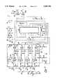
- FIG. 3is a schematic circuit diagram of the circuitry of the optical read head of FIG. 2;
- FIG. 4is a flow diagram of the software program for the microcontroller of the circuit of FIG. 3.
- the tank 10is a generalized tank for purposes of illustration, and it will be appreciated that specific types of tanks, such as barge tanks or railway car tanks, e.g., may differ in specific structural details.
- the tank 10has a side wall 11, a bottom wall 12 and a top wall 13.
- a liquid 14may be stored within the tank 10.
- the top wall 13has an opening therein with which a nozzle 15 is aligned.
- the nozzle 15extends upwardly from the top wall 13 and includes a cylinder 16 welded thereto.
- a ring-shaped flange 17is welded to the top of the cylinder 16 and a mounting plate 18 is attached to the flange 17, as by bolts 19 (only two of which are shown).
- a gauge 20, constructed in accordance with and embodying the features of the present invention,is provided for determining the level of the liquid 14 within the tank 10.
- the gauge 20includes an elongated guide tube 21 which is preferably composed of corrosion-resistant, non-magnetic material in order to withstand corrosive liquids which may be stored in the tank 10.
- the guide tube 21extends through a complementary opening in the mounting plate 18, and is fixed thereto, as by weldments 22.
- the guide tube 21has an upper end 23 which may be externally threaded.
- a sealing plug or cap 24is seal welded on the lower end of the guide tube 21.
- a bushing 25is disposed in the upper end 23 of the guide tube 21 and has an axial bore therethrough.
- An inverted cup-shaped cap 26closes the upper end 23 of the guide tube 21 and may be threadedly engaged therewith, the cap 26 having an axial bore therethrough coaxial with the bore in the bushing 25.
- the gauge 20includes a float 30 having a hollow, substantially spherical shell 31 and a central tube 32 hermetically attached together.
- the guide tube 21passes coaxially through the float tube 32 so that the float 30 can freely move along the guide tube 21 with change in liquid level.
- the float 30is also preferably made of a corrosion-resistant, non-magnetic material.
- a ring-shaped magnet 33is mounted within the float 30 and encircles the tube 32, being fixed to the tube 32 and/or to the inner surface of the shell 31.
- the gauge 20also includes an elongated cylindrical gauging rod or tube 35 which is disposed coaxially within the guide tube 21, with the upper end of the gauging rod 35 extending through the coaxial bores in the bushing 25 and the cap 26.
- Fixed to the lower end of the gauging rod 35is a cylindrical magnet 36, which magnetically couples the gauging rod 35 to the float magnet 33 and, thereby, to the float 30, in a known manner, so that the gauging rod 35 rises and falls with the float 30 as the level of the liquid 14 rises and falls.
- the gauging rod 35has a cylindrical code-bearing outer surface 37.
- the code-bearing surface 37has dark or non-reflective zones 38 and 39, respectively at the lower and upper ends thereof, each of the zones 38 and 39 preferably being covered around the entire circumference of the surface 37 with a black or otherwise non-reflective color.
- the remainder of the code-bearing surface 37, intermediate the zones 38 and 39,is provided with alternating light and dark stripes 40 and 41, each extending around the circumference of the surface 37 and each having the same longitudinal height.
- the light stripes 40are light-reflecting and may comprise a coating of a white or other suitable light-reflecting color, while the dark stripes 41 are non-reflecting and may be of the same type as the dark zones 38 and 39. It will be appreciated that the zones 38 and 39 and the stripes 40 and 41 comprise the code indicia of the code-bearing surface 37. If desired, human-readable indicia 43 could also be provided on the light stripes 40, as will be discussed further below.
- the gauge 20also includes a code sensor in the form of an optical read head 45, which is preferably mounted on the cap 26 alongside the gauging rod 35, as illustrated in FIG. 1.
- the contents of the optical read head 45are illustrated in functional block form in FIG. 2 and in schematic form in FIG. 3.
- the optical read head 45includes a pair of light sources, such as light-emitting diodes ("LEDs") 46A and 46B disposed for illuminating the adjacent portion of the code-bearing surface 37.
- the LEDs 46A and 46Bflank an array of four optical sensors, such as photodiodes 47A-47D, which are preferably arranged in two pairs, each of which is arranged in quadrature relationship relative to the code-bearing surface 37.
- the spacing of the photodiodes 47A-47Dis such that each "reads" a region of the code-bearing surface 37 having a vertical or longitudinal extent at least one-half the height of a stripe 40 or 41.
- the field of view of each of the photodiodes 47A-Dis approximately the height of a stripe 40 or 41.
- the field of viewshould not be significantly wider than the height of a stripe, so that the photodiode cannot simultaneously detect an entire light stripe plus an entire dark stripe, in which case it would not be able to distinguish between light and dark stripes.
- the photodiodes of each pairare disposed 90° out of phase with each other.
- the photodiodes 47A and 47Bwhen the photodiode 47A is in the center of a stripe so as to be detecting all white (or all dark) the photodiode 47B is at the boundary between two stripes so it is detecting half light and half dark. It will be appreciated that this condition will be true when the two photodiodes of a pair are spaced apart by odd multiples of one-half stripe width, e.g., 1/2, 3/2, 5/2, etc.
- the pairs of photodiodesare disposed 180° out of phase, so that when a photodiode of one pair is disposed in the center of a white stripe so as to be detecting all light, the corresponding photodiode of the adjacent pair is in the center of a dark stripe, so as to be detecting all dark. It will be appreciated that this is true if the pairs are spaced apart by odd multiples of a stripe width, e.g., 1, 3, 5, etc.
- the height of the stripes 40 and 41will determine the resolution of the gauge 20 and, thereby, the precision of the level measurements, the resolution being proportional to the height of the stripes. It will be appreciated that if the height of the stripes changes, the spacing and field of view of the photodiodes 47A-D would be changed accordingly. While, in the illustrated embodiment, two light sources 46A and 46B are utilized, it will be appreciated that a single source could be used as long as it illuminates the region in the field of view of the optical sensors 47A-D.
- the optical read head 45outputs signals to an associated control panel state processor 49 for providing liquid level indications to a user, as will be explained more fully below.
- the optical read head 45also includes a control circuit 50, which includes a power supply 51, a microcontroller 59 operating under stored program control, and a detection circuit 60.
- the power supply 51includes a voltage regulator 52 and associated capacitors 53 and 54 and converts a DC supply voltage V++ which may, for example, be 12 VDC, to a V+ voltage such as, for example, 5 VDC in a known manner.
- V++DC supply voltage
- V+ voltagesuch as, for example, 5 VDC in a known manner.
- the LEDs 46A and 46BConnected in series between the V+ supply and ground are the LEDs 46A and 46B, the collector-emitter junction of a transistor 55 and a resistor 56.
- the base of the transistor 55is connected to the V+ supply through a resistor 57 and is also connected to an output pin of the microcontroller 59 which generates a high-frequency pulsed current waveform, which preferably has a frequency of about 20 KHz and 50% duty cycle with a peak current of approximately 80 mA.
- a high-frequency pulsed current waveformwhich preferably has a frequency of about 20 KHz and 50% duty cycle with a peak current of approximately 80 mA.
- Each of the photodiodes 47A-Dhas its cathode connected to the V++ supply and its anode connected to a corresponding one of four amplifier-demodulator circuits 65A-65D, which are substantially identical in construction, so that only the circuit 65A will be described in detail.
- the anode of the photodiode 47Ais connected to one plate of a capacitor 62, which plate is also connected to ground through a current drain resistor 61.
- the other plate of the capacitor 62is connected to the inverting input of an operational amplifier (“op amp") 64, which terminal is also connected to the output of the amplifier 64 through a feedback resistor 66.
- op ampoperational amplifier
- the non-inverting input of the amplifier 64is connected to the junction between resistors 67 and 68, which form a voltage divider connected in series between the V+supply and ground. It will be appreciated that the amplifiers 64 for the several circuits 65A-D may constitute a quad op amp connected to the V++ supply voltage.
- An AC shunt capacitors 69a and 69bare, respectively, connected in parallel with the amplifiers 64 and the resistor 68.
- the output of the amplifier 64is connected to the anode of a rectifying diode 70, the cathode of which is connected to the non-inverting input of an op amp configured as a comparator 75.
- a capacitor 71 and a resistor 72are connected in parallel between the cathode of the diode 70 and ground, the capacitor 71 serving to preserve the peak voltage at the output of the diode 70 and the resistor 72 serving as a current drain.
- the inverting input of the comparator 75is connected to the junction between a diode 77 and a resistor 78, which form a voltage divider connected in series between the V+ supply and ground. It will be appreciated that the comparators 75 of the circuits 65A-D may form parts of a quad op amp supplied with the V++ supply voltage and connected in parallel with an AC shunt capacitor 76.
- the outputs of the comparators 75are, respectively, input to the microcontroller 59 at bits 0, 1, 4 and 5 of one port of the microcontroller, which observes the states of these input lines and their transitions to track the position of the gauging rod 35.
- a crystal 81is connected across clock terminals of the microcontroller 59, which terminals are connected to ground through capacitors 82 and 83, respectively, to form an oscillating circuit to control the clock frequency of the microcontroller 59.
- a reset terminal of the microcontroller 59is connected through a reset capacitor 84 to the V+ supply.
- the V+ supply voltageis also supplied to a supply terminal of the microcontroller 59, which is shunted by a bypass capacitor 85.
- the outputs from the microcontroller 59are taken at the two lowest order bits of a second port and are, respectively, input to the inverting input terminals of buffer op amps 90A and 90B configured as comparators.
- the non-inverting inputs of these comparatorsare connected to the junction between resistors 92 and 93, which form a voltage divider connected in series between the V+ supply and ground.
- the comparators 90A and 90Bmay be embodied in a quad op amp, supplied with the V++ supply voltage shunted by a bypass capacitor 91.
- the outputs of the op amps 90A and 90Bare, respectively, fed via lines 96 and 97 to the control panel state processor 49.
- the microcontroller 59is programmed to provide a serial output pulse train on one of the output lines, the other being used to provide a clock signal for syncing the output.
- the serial output datacan give an indication of discrete alarm levels or a continuous indication of absolute liquid level, depending upon the condition of a configuration bit input at the highest order bit of port 1.
- the microcontroller 59outputs a square wave which is buffered by the transistor 55, which powers the LEDs 46A and 46B with a 50% duty cycle current, turning the LEDs on and off at a 20 KHz rate to modulate their light output at the 20 KHz modulation frequency.
- the light from the LEDs 46A and 46Bwhich may be infrared emitters, illuminates the adjacent portion of the code-bearing surface 37 of the gauging rod 35.
- the modulated infrared light which is reflected from the code-bearing surface 37is detected by the photodiodes 47A-D.
- the voltages at the anodes of the photodiodesare proportional to the strength of the infrared light striking them.
- each comparator 75represents the strength of the light striking the associated one of the photodiodes 47A-D.
- These DC signalschange relatively slowly (typically less than 100 Hz for reasonable gauging rod motions), and are compared by the comparator 75 with a reference voltage created by the voltage divider comprising the diode 77 and the resistor 78.
- Basic liquid level determinationis performed using the well-known quadrature encoding technique, with the photodiodes 47A-D being arranged in two quadrature pairs.
- the pattern of logic levels from each of these pairscan indicate the direction in which the liquid level is changing, in a known manner, described, for example, in U.S. Pat. No. 5,245,874.
- the microcontrollermaintains a count of the light/dark transitions relative to a reference level to determine absolute position.
- An important feature of the present inventionis the use of four detectors instead of a single quadrature pair.
- This arrangementtogether with the provision of the dark zones 38 and 39 at the ends of the gauging rod 35, afford significant advantages.
- Each of the dark zones 38 and 39has a longitudinal extent or length at least as great as the height of two stripes 40, 41 such that, in either of the full or empty conditions, the fields of view of all four photodiodes 47A-D will be completely within one or the other of the dark zones 38 and 39, so that the outputs of all four of the photodiodes 47A-D will be "dark". This will uniquely indicate that the rod 35 is in one of its two limit positions since, in any other position, at least one of the photodiodes will register "light”.
- the length of the gauging rod 35is such that these zones 38 and 39, respectively, correspond to the full and empty conditions of the tank. Furthermore, by interpreting the sequence of transitions by which the photodiodes enter and leave the all-dark condition, the microcontroller 59 can interpret which of the zones 38 and 39 is being entered or exited. These end zones 38 and 39 establish reference levels for the counting operation Of the microcontroller 59.
- the unique arrangement of four photodiodesalso means that, in normal operation, at least one of the photodiodes will always be registering a "dark" output. Thus, this constitutes a fail-safe feature since, if all of the photodiode outputs are "light,” this indicates a fault condition. Also, by following the pattern of transitions between light and dark of the several photodiodes 47A-D, the microcontroller 59 can detect aberrant patterns which would indicate failure or disconnection of a photodiode.
- each rectifying diode 70is essentially the average strength of the modulated detected light, which is then compared to a fixed threshold to accurately determine whether the associated photodiode is viewing a light stripe or a dark stripe.
- the average or total light level detected by all photodiodes 47A-Dis constant and could be used as a threshold level for comparison with each one to determine the logic level of the detector. This would substantially reduce sensitivity to background light levels that could be troublesome if only one pair of detectors were used.
- the microcontroller 59observes the ON-OFF state of the four signals coming from the amplifier-demodulator circuits 65A-D and utilizes the state transitions to track the position of the gauging rod 35. Thus, the microcontroller 59 tracks the position of the gauging rod 35 and generates a serial output data stream which will indicate either that a predetermined alarm level has been reached, or will give a continuous reading of the absolute position of the gauging rod 35, depending upon the mode of operation of the microcontroller 59, as determined by the condition of the jumper contacts 95.
- FIG. 4there is illustrated a flow chart of the program software 100 for the microcontroller 59.
- the control circuit 50When the control circuit 50 is powered up at 101, it moves at 102 to a shutdown condition, which is a default state, awaiting detection of movement of the gauging rod 35, since the gauging function of the control circuit 50 can only work if the gauging rod 35 is moving.
- a shutdown conditionwhich is a default state, awaiting detection of movement of the gauging rod 35, since the gauging function of the control circuit 50 can only work if the gauging rod 35 is moving.
- the gauging rod 35is in a rest position fully retracted into the tank 10, with the top of the rod adjacent to the read head 45. If the tank is not empty, the magnets 33 and 36 will be decoupled. After power up, the gauging rod 35 is manually raised sufficiently to couple the magnets 33 and 36.
- the programchecks at 103 to see if the pattern of photodiode outputs indicates that the optical read head is leaving the dark zone 39 at the top of the gauging rod 35, indicating that the tank is empty. If the read head 45 is not at the top of the rod, the program returns to the default condition at 102. If it is at the top of the rod, the program proceeds to a start sequence at 104, wherein both of the output lines 96 and 97 go high. Then two software counters, one for each quadrature pair of the photodiodes 47A-D, are initialized at 105.
- the programthen checks the status of the input ports of the microcontroller 59 at 106, adjusts counter 0 at 107 and then checks at 108 to see if an error is indicated. If it is, the program returns to the default condition at 102. If there is no error the program adjusts counter 1 at 109 and again checks for errors at 110. If there are no errors, the program checks at 111 to see if the states of the counters are substantially equal, i.e., within one count of each other. If they are not, this indicates that something is wrong and the program returns to the default condition at 102. If the counters are equal, the program checks at 112 to see if the jumper is in place at the contacts 95.
- the systemis set to provide a continuous output reading of absolute position of the gauge and, accordingly, the program sends the position as a serial data stream to the output port at 113, and the program returns to 106 to again check the status of the input ports. If the jumper is not in place, then the program is set to detect alarm levels. Accordingly, the program checks at 114 to see if an alarm level has been reached. If not, the program returns to 106 to continue checking the status of the input ports.
- the programsends the level indicating pulses to the output port at 115 and then checks at 116 to see if the tank is full, as determined by the photodiode outputs indicating that the optical read head 45 has entered the dark zone 38 at the bottom of the gauging rod 35. If the tank is not full, the program returns to again continue checking the status of the input ports at 106. If the tank is full, the program reverts to the default condition at 102.
- the microcontroller outputswhich can source only a relatively small amount of current, are buffered by the push-pull op amps 90A and 90B, which can sink and source up to 8 mA.
- the output signals from the microcontroller 59are supplied to the control panel state processor 49, which may produce a suitable output signal display indicating the alarm level or the absolute level position in user-readable format.
- the gauging rod 35there may also be provided user-readable indicia 43 on the gauging rod 35, which can be directly read by a user without the use of the optical read head 45.
- these indiciaare so arranged on the light stripes 40 that they do not excessively change the optical reflectance of the light stripes. Because the stripes 40 and 41 extend circumferentially around the gauging rod 35, the rod can rotate to any orientation without affecting the optical readout.
- the microcontroller 59may be an 87C750
- the transistor 55may be a 2N2222
- the amplifiers 64may be an LF347
- the comparators 75may be an LM339
- the comparators 90A and 90Bmay be a TLC3704.
- an improved optical float gaugefor determining liquid level in a tank, the gauge providing both electronic and directly-visible level indications, the ability to detect both full and empty conditions, the ability to detect absolute liquid level as well as discrete alarm levels and to provide user selection between these modes of operation, a fail-safe encoding technique to indicate invalid states of the detectors, and relative immunity to ambient light.
Landscapes
- Physics & Mathematics (AREA)
- Fluid Mechanics (AREA)
- General Physics & Mathematics (AREA)
- Length Measuring Devices By Optical Means (AREA)
Abstract
Description
Claims (18)
Priority Applications (1)
| Application Number | Priority Date | Filing Date | Title |
|---|---|---|---|
| US08/550,386US5585786A (en) | 1995-10-30 | 1995-10-30 | Optical tank-level gauge |
Applications Claiming Priority (1)
| Application Number | Priority Date | Filing Date | Title |
|---|---|---|---|
| US08/550,386US5585786A (en) | 1995-10-30 | 1995-10-30 | Optical tank-level gauge |
Publications (1)
| Publication Number | Publication Date |
|---|---|
| US5585786Atrue US5585786A (en) | 1996-12-17 |
Family
ID=24196965
Family Applications (1)
| Application Number | Title | Priority Date | Filing Date |
|---|---|---|---|
| US08/550,386Expired - Fee RelatedUS5585786A (en) | 1995-10-30 | 1995-10-30 | Optical tank-level gauge |
Country Status (1)
| Country | Link |
|---|---|
| US (1) | US5585786A (en) |
Cited By (29)
| Publication number | Priority date | Publication date | Assignee | Title |
|---|---|---|---|---|
| US5874899A (en)* | 1998-02-06 | 1999-02-23 | Midland Manufacturing Corp. | Tank level gauge and sensor head therefor |
| US6012606A (en)* | 1996-06-27 | 2000-01-11 | Eastman Kodak Company | Apparatus for detecting low liquid level in bottom-draining container |
| EP1010971A1 (en)* | 1998-12-15 | 2000-06-21 | BSH Bosch und Siemens Hausgeräte GmbH | Device for measuring the liquid level in a container |
| US6175748B1 (en)* | 1998-02-09 | 2001-01-16 | Lucent Technologies Inc. | Methods and apparatus for determination of a power level in an RF booster for wireless communications |
| US6546797B2 (en) | 2000-08-24 | 2003-04-15 | Mlho, Inc. | Absolute position measure with multi-beam optical encoding |
| US6561022B1 (en)* | 1999-06-15 | 2003-05-13 | Scientific Generics Limited | Position encoder |
| GB2388897A (en)* | 2002-05-25 | 2003-11-26 | Arthur Robert Butler | Liquid level measurement |
| US6672156B1 (en)* | 2001-08-08 | 2004-01-06 | Mlno, Inc. | Absolute liquid level sensor with refractive encoding |
| US6696966B2 (en)* | 2001-04-16 | 2004-02-24 | Usf Consumer & Commercial Watergroup, Inc. | Automatic salt level monitor for a water softening device |
| US20060142953A1 (en)* | 2003-02-06 | 2006-06-29 | Endress + Hauser Gmbh + Co. Kg | Device and method for determining and/or monitoring a process variable of a medium |
| US20060139177A1 (en)* | 2004-12-13 | 2006-06-29 | Gomery Victor E | Low oil level indicator |
| WO2007068889A1 (en)* | 2005-12-12 | 2007-06-21 | The Validation Centre (Tvc) Limited | A float transducer |
| US20070236914A1 (en)* | 2005-10-03 | 2007-10-11 | Cox Raleigh L | Optical Switch |
| US20080297359A1 (en)* | 2007-05-31 | 2008-12-04 | Cox Raleigh L | Optical Switch |
| US20090111812A1 (en)* | 2004-06-14 | 2009-04-30 | Musc Foundation For Research Development | Methods for treating inflammatory disorders |
| US20100066548A1 (en)* | 2007-05-31 | 2010-03-18 | Cox Raleigh L | Optical Switch |
| US8334501B1 (en) | 2008-10-16 | 2012-12-18 | Cox Christopher E | Optical switch activator with glowable member |
| US8643498B1 (en) | 2010-07-13 | 2014-02-04 | Christopher E. Cox | Optical switches for tank environments |
| US20140260603A1 (en)* | 2013-03-14 | 2014-09-18 | Marshall Excelsior Co. | Float gauge assembly for storage tanks |
| US20150020604A1 (en)* | 2011-10-24 | 2015-01-22 | Michael Myungsub Lee | Apparatus and method for measuring the sloshing in the cargo tank of a liquefied natural gas carrier |
| US20150177050A1 (en)* | 2013-12-20 | 2015-06-25 | Texas Lfp, Llc | Liquid level gauge with float guides |
| US20150316509A1 (en)* | 2013-07-02 | 2015-11-05 | Mitsubishi Materials Corporation | Method for measuring thickness of boiler water tube |
| US9383518B2 (en) | 2012-12-14 | 2016-07-05 | Christopher E. Cox | Optical switch activator |
| CN102954825B (en)* | 2011-08-26 | 2017-05-03 | 曼卡车和巴士股份公司 | Operating method for a vehicle |
| WO2018040192A1 (en)* | 2016-08-31 | 2018-03-08 | 无锡小天鹅股份有限公司 | Laundry machine |
| US10012757B2 (en) | 2016-01-21 | 2018-07-03 | King Fahd University Of Petroleum And Minerals | Method and apparatus for measuring a local acceleration of gravity |
| US10840045B1 (en) | 2019-06-04 | 2020-11-17 | Christopher E. Cox | Invertible optical float switch |
| US11464215B2 (en)* | 2018-03-19 | 2022-10-11 | Gerard A. Calabrese | Measurement apparatus for measuring a specific gravity of a liquid, and saltwater aquarium salinity control system |
| US20240044687A1 (en)* | 2020-10-29 | 2024-02-08 | Patlite Corporation | Level meter and method of setting the level meter |
Citations (17)
| Publication number | Priority date | Publication date | Assignee | Title |
|---|---|---|---|---|
| US4079627A (en)* | 1975-05-05 | 1978-03-21 | Devtron Corporation | Absolute digital position measurement system |
| US4286464A (en)* | 1980-01-14 | 1981-09-01 | Technical Development Company | Optical fluid level monitor |
| US4450722A (en)* | 1982-07-26 | 1984-05-29 | The Babcock & Wilcox Company | Water level gauge with fault detector |
| US4501972A (en)* | 1982-03-01 | 1985-02-26 | Scans Associates, Inc. | Float detection system |
| US4739786A (en)* | 1984-11-01 | 1988-04-26 | Craig Parkinson | Liquid level monitoring assemblies |
| US4745293A (en)* | 1987-03-23 | 1988-05-17 | Cv Technology, Inc. | Method and apparatus for optically measuring fluid levels |
| US4768377A (en)* | 1985-11-16 | 1988-09-06 | General Motors Corporation | Method and apparatus for measuring the liquid level in tanks subjected to varying accelerations |
| US4857894A (en)* | 1988-06-27 | 1989-08-15 | The United States Of America As Represented By The Secretary Of The Navy | Liquid level measurement system for analog and digital readout |
| US4866428A (en)* | 1988-03-08 | 1989-09-12 | Illinois Tool Works, Inc. | Remote battery cell specific gravity and electrolytic level monitor using floats and optical couplers |
| US5054319A (en)* | 1990-09-12 | 1991-10-08 | Fling John J | Liquid level sensor and method |
| US5073253A (en)* | 1990-07-11 | 1991-12-17 | Phillips Petroleum Company | Froth level measurement |
| US5124686A (en)* | 1990-12-31 | 1992-06-23 | Midland Manufacturing Corp. | Tank level alarm control system |
| US5142793A (en)* | 1989-06-02 | 1992-09-01 | Contek Corporation | Digital linear measuring device |
| US5146784A (en)* | 1991-03-04 | 1992-09-15 | Vista Research, Inc. | Sensor for measuring liquid-level changes in storage tanks |
| US5156042A (en)* | 1987-07-17 | 1992-10-20 | Proeco, Inc. | Leak detector |
| US5245874A (en)* | 1992-04-10 | 1993-09-21 | Rainwise, Inc. | Total precipitation gauge with float sensor |
| US5421193A (en)* | 1993-12-30 | 1995-06-06 | Proeco, Inc. | Method and apparatus for leak detection with float excitation and self-calibration |
- 1995
- 1995-10-30USUS08/550,386patent/US5585786A/ennot_activeExpired - Fee Related
Patent Citations (17)
| Publication number | Priority date | Publication date | Assignee | Title |
|---|---|---|---|---|
| US4079627A (en)* | 1975-05-05 | 1978-03-21 | Devtron Corporation | Absolute digital position measurement system |
| US4286464A (en)* | 1980-01-14 | 1981-09-01 | Technical Development Company | Optical fluid level monitor |
| US4501972A (en)* | 1982-03-01 | 1985-02-26 | Scans Associates, Inc. | Float detection system |
| US4450722A (en)* | 1982-07-26 | 1984-05-29 | The Babcock & Wilcox Company | Water level gauge with fault detector |
| US4739786A (en)* | 1984-11-01 | 1988-04-26 | Craig Parkinson | Liquid level monitoring assemblies |
| US4768377A (en)* | 1985-11-16 | 1988-09-06 | General Motors Corporation | Method and apparatus for measuring the liquid level in tanks subjected to varying accelerations |
| US4745293A (en)* | 1987-03-23 | 1988-05-17 | Cv Technology, Inc. | Method and apparatus for optically measuring fluid levels |
| US5156042A (en)* | 1987-07-17 | 1992-10-20 | Proeco, Inc. | Leak detector |
| US4866428A (en)* | 1988-03-08 | 1989-09-12 | Illinois Tool Works, Inc. | Remote battery cell specific gravity and electrolytic level monitor using floats and optical couplers |
| US4857894A (en)* | 1988-06-27 | 1989-08-15 | The United States Of America As Represented By The Secretary Of The Navy | Liquid level measurement system for analog and digital readout |
| US5142793A (en)* | 1989-06-02 | 1992-09-01 | Contek Corporation | Digital linear measuring device |
| US5073253A (en)* | 1990-07-11 | 1991-12-17 | Phillips Petroleum Company | Froth level measurement |
| US5054319A (en)* | 1990-09-12 | 1991-10-08 | Fling John J | Liquid level sensor and method |
| US5124686A (en)* | 1990-12-31 | 1992-06-23 | Midland Manufacturing Corp. | Tank level alarm control system |
| US5146784A (en)* | 1991-03-04 | 1992-09-15 | Vista Research, Inc. | Sensor for measuring liquid-level changes in storage tanks |
| US5245874A (en)* | 1992-04-10 | 1993-09-21 | Rainwise, Inc. | Total precipitation gauge with float sensor |
| US5421193A (en)* | 1993-12-30 | 1995-06-06 | Proeco, Inc. | Method and apparatus for leak detection with float excitation and self-calibration |
Cited By (45)
| Publication number | Priority date | Publication date | Assignee | Title |
|---|---|---|---|---|
| US6012606A (en)* | 1996-06-27 | 2000-01-11 | Eastman Kodak Company | Apparatus for detecting low liquid level in bottom-draining container |
| US5874899A (en)* | 1998-02-06 | 1999-02-23 | Midland Manufacturing Corp. | Tank level gauge and sensor head therefor |
| US6175748B1 (en)* | 1998-02-09 | 2001-01-16 | Lucent Technologies Inc. | Methods and apparatus for determination of a power level in an RF booster for wireless communications |
| EP1010971A1 (en)* | 1998-12-15 | 2000-06-21 | BSH Bosch und Siemens Hausgeräte GmbH | Device for measuring the liquid level in a container |
| US6561022B1 (en)* | 1999-06-15 | 2003-05-13 | Scientific Generics Limited | Position encoder |
| US6546797B2 (en) | 2000-08-24 | 2003-04-15 | Mlho, Inc. | Absolute position measure with multi-beam optical encoding |
| US6696966B2 (en)* | 2001-04-16 | 2004-02-24 | Usf Consumer & Commercial Watergroup, Inc. | Automatic salt level monitor for a water softening device |
| CN100335871C (en)* | 2001-04-16 | 2007-09-05 | 卡乐根国际公司 | Automatic salt level monitor for water softening device |
| US6672156B1 (en)* | 2001-08-08 | 2004-01-06 | Mlno, Inc. | Absolute liquid level sensor with refractive encoding |
| GB2388897A (en)* | 2002-05-25 | 2003-11-26 | Arthur Robert Butler | Liquid level measurement |
| US20060142953A1 (en)* | 2003-02-06 | 2006-06-29 | Endress + Hauser Gmbh + Co. Kg | Device and method for determining and/or monitoring a process variable of a medium |
| US7424373B2 (en)* | 2003-02-06 | 2008-09-09 | Endress + Hauser Gmbh + Co. Kg | Device and method for determining and/or monitoring a process variable of a medium |
| US20090111812A1 (en)* | 2004-06-14 | 2009-04-30 | Musc Foundation For Research Development | Methods for treating inflammatory disorders |
| US20060139177A1 (en)* | 2004-12-13 | 2006-06-29 | Gomery Victor E | Low oil level indicator |
| US7772538B2 (en) | 2005-10-03 | 2010-08-10 | Cox Raleigh L | Float activated optical switch |
| US20070236914A1 (en)* | 2005-10-03 | 2007-10-11 | Cox Raleigh L | Optical Switch |
| WO2007068889A1 (en)* | 2005-12-12 | 2007-06-21 | The Validation Centre (Tvc) Limited | A float transducer |
| US8314711B2 (en) | 2007-05-31 | 2012-11-20 | Raleigh L Cox | Optical switch |
| US7714732B2 (en)* | 2007-05-31 | 2010-05-11 | Cox Raleigh I | Optical switch |
| US20100066548A1 (en)* | 2007-05-31 | 2010-03-18 | Cox Raleigh L | Optical Switch |
| US7902989B2 (en) | 2007-05-31 | 2011-03-08 | Cox Raleigh L | Optical switch |
| US20110170824A1 (en)* | 2007-05-31 | 2011-07-14 | Cox Raleigh L | Optical Switch |
| US20080297359A1 (en)* | 2007-05-31 | 2008-12-04 | Cox Raleigh L | Optical Switch |
| US8334501B1 (en) | 2008-10-16 | 2012-12-18 | Cox Christopher E | Optical switch activator with glowable member |
| US8658962B2 (en) | 2008-10-16 | 2014-02-25 | Christopher E. Cox | Optical switch with glowable activator portion |
| US8643498B1 (en) | 2010-07-13 | 2014-02-04 | Christopher E. Cox | Optical switches for tank environments |
| CN102954825B (en)* | 2011-08-26 | 2017-05-03 | 曼卡车和巴士股份公司 | Operating method for a vehicle |
| US9709389B2 (en)* | 2011-10-24 | 2017-07-18 | Michael Myungsub Lee | Apparatus and method for measuring the sloshing in the cargo tank of a liquefied natural gas carrier |
| US20150020604A1 (en)* | 2011-10-24 | 2015-01-22 | Michael Myungsub Lee | Apparatus and method for measuring the sloshing in the cargo tank of a liquefied natural gas carrier |
| US9383518B2 (en) | 2012-12-14 | 2016-07-05 | Christopher E. Cox | Optical switch activator |
| US9562800B2 (en)* | 2013-03-14 | 2017-02-07 | Marshall Excelsior Co. | Float gauge assembly for storage tanks |
| US20140260603A1 (en)* | 2013-03-14 | 2014-09-18 | Marshall Excelsior Co. | Float gauge assembly for storage tanks |
| US10458835B2 (en) | 2013-03-14 | 2019-10-29 | Marshall Excelsior Co. | Float gauge assembly for storage tanks |
| US20150316509A1 (en)* | 2013-07-02 | 2015-11-05 | Mitsubishi Materials Corporation | Method for measuring thickness of boiler water tube |
| US20150177050A1 (en)* | 2013-12-20 | 2015-06-25 | Texas Lfp, Llc | Liquid level gauge with float guides |
| US10114145B1 (en) | 2016-01-21 | 2018-10-30 | King Fahd University Of Petroleum And Minerals | Acceleration measurement apparatus |
| US10012757B2 (en) | 2016-01-21 | 2018-07-03 | King Fahd University Of Petroleum And Minerals | Method and apparatus for measuring a local acceleration of gravity |
| US10126461B2 (en) | 2016-01-21 | 2018-11-13 | King Fahd University Of Petroleum And Minerals | LED/photodiode apparatus for measuring acceleration |
| US11119247B2 (en) | 2016-01-21 | 2021-09-14 | King Fahd University Of Petroleum And Minerals | Measurement apparatus with circuitry for measuring acceleration |
| US11119246B2 (en) | 2016-01-21 | 2021-09-14 | King Fahd University Of Petroleum And Minerals | IR timing apparatus for measuring acceleration |
| WO2018040192A1 (en)* | 2016-08-31 | 2018-03-08 | 无锡小天鹅股份有限公司 | Laundry machine |
| US11464215B2 (en)* | 2018-03-19 | 2022-10-11 | Gerard A. Calabrese | Measurement apparatus for measuring a specific gravity of a liquid, and saltwater aquarium salinity control system |
| US10840045B1 (en) | 2019-06-04 | 2020-11-17 | Christopher E. Cox | Invertible optical float switch |
| US20240044687A1 (en)* | 2020-10-29 | 2024-02-08 | Patlite Corporation | Level meter and method of setting the level meter |
| US11971288B2 (en)* | 2020-10-29 | 2024-04-30 | Patlite Corporation | Level meter and method of setting the level meter |
Similar Documents
| Publication | Publication Date | Title |
|---|---|---|
| US5585786A (en) | Optical tank-level gauge | |
| US5874899A (en) | Tank level gauge and sensor head therefor | |
| CN102301209B (en) | Flow meter | |
| FI73835C (en) | VATTENNAAAAETARE MED FELDETEKTOR. | |
| US5056049A (en) | Position Transmitter | |
| US4181610A (en) | Blood leak detector suitable for use with artificial kidneys | |
| US5218771A (en) | Orientation sensing apparatus | |
| US7725273B2 (en) | Apparatus for monitoring height of liquid in storage tank | |
| US4154000A (en) | Remote level sensing instrument | |
| CA2052448C (en) | Tank level alarm control system | |
| EP0626568B1 (en) | Liquid gauging apparatus and remote sensor interrogation | |
| JPH05133732A (en) | Read head | |
| US6299020B1 (en) | Beverage dispenser sensor system | |
| US5237857A (en) | Down-hole liquid detecting apparatus | |
| JPH01501098A (en) | absolute measurement scale device | |
| US4482891A (en) | Robust electronic liquid level gauge | |
| US6661504B2 (en) | Failure detecting optoelectronic sensor | |
| US6166630A (en) | Wireless fuel gauge | |
| US4864870A (en) | Analog flow meter instrument | |
| JP2857335B2 (en) | Piston position detector | |
| EP0130738B1 (en) | Electronic levelling device | |
| CA2629929A1 (en) | Magnetic field position sensor and method of use | |
| CN212963522U (en) | Sampling counting assembly of metering device and metering device with sampling counting assembly | |
| KR100366645B1 (en) | Measuring apparatus for iquid level stored in the bottle | |
| JPH0714809Y2 (en) | Optical displacement meter |
Legal Events
| Date | Code | Title | Description |
|---|---|---|---|
| AS | Assignment | Owner name:MIDLAND MANUFACTURING CORP., ILLINOIS Free format text:ASSIGNMENT OF ASSIGNORS INTEREST;ASSIGNORS:CLARK, REECE ROBERT;BARMORE, GASTON C., JR.;REEL/FRAME:007770/0771;SIGNING DATES FROM 19951011 TO 19951016 | |
| AS | Assignment | Owner name:MIDLAND MANUFACTURING CORP., ILLINOIS Free format text:ASSIGNMENT OF ASSIGNORS INTEREST;ASSIGNORS:CLARK, REECE ROBERT;BARMORE, JR., GASTON C.;REEL/FRAME:008198/0091;SIGNING DATES FROM 19960506 TO 19960604 | |
| AS | Assignment | Owner name:DELAWARE CAPITAL FORMATION, INC., DELAWARE Free format text:ASSIGNMENT OF ASSIGNORS INTEREST;ASSIGNOR:MIDLAND MANUFACTURING CORP.;REEL/FRAME:010470/0960 Effective date:19991111 | |
| FPAY | Fee payment | Year of fee payment:4 | |
| AS | Assignment | Owner name:FIRST UNION NATIONAL BANK, NORTH CAROLINA Free format text:SECURITY INTEREST;ASSIGNOR:MIDLAND MANUFACTURING COMPANY, INC.;REEL/FRAME:013563/0511 Effective date:20020327 | |
| AS | Assignment | Owner name:MIDLAND MANUFACTURING COMPANY, INC., GRANTOR, SOUT Free format text:RELEASE BY SECURED PARTY;ASSIGNOR:WACHOVIA BAK, NATIONAL ASSOCIATION, AS SUCCESSOR TO FIRST UNION NATIONAL BANK, AS ADMINISTRATIVE AGENT;REEL/FRAME:014051/0989 Effective date:20030912 | |
| FPAY | Fee payment | Year of fee payment:8 | |
| REMI | Maintenance fee reminder mailed | ||
| LAPS | Lapse for failure to pay maintenance fees | ||
| STCH | Information on status: patent discontinuation | Free format text:PATENT EXPIRED DUE TO NONPAYMENT OF MAINTENANCE FEES UNDER 37 CFR 1.362 | |
| FP | Lapsed due to failure to pay maintenance fee | Effective date:20081217 |