US5585749A - High current driver providing battery overload protection - Google Patents
High current driver providing battery overload protectionDownload PDFInfo
- Publication number
- US5585749A US5585749AUS08/363,785US36378594AUS5585749AUS 5585749 AUS5585749 AUS 5585749AUS 36378594 AUS36378594 AUS 36378594AUS 5585749 AUS5585749 AUS 5585749A
- Authority
- US
- United States
- Prior art keywords
- high current
- battery
- current
- voltage
- magnitude
- Prior art date
- Legal status (The legal status is an assumption and is not a legal conclusion. Google has not performed a legal analysis and makes no representation as to the accuracy of the status listed.)
- Expired - Lifetime
Links
- 230000002401inhibitory effectEffects0.000claimsabstractdescription11
- 238000004891communicationMethods0.000claimsdescription32
- 238000005265energy consumptionMethods0.000claimsdescription7
- 230000004044responseEffects0.000claimsdescription7
- 238000010586diagramMethods0.000description12
- 230000002829reductive effectEffects0.000description7
- 230000001276controlling effectEffects0.000description6
- 230000006870functionEffects0.000description6
- 229920006395saturated elastomerPolymers0.000description6
- 238000005286illuminationMethods0.000description5
- 238000013459approachMethods0.000description4
- 238000000034methodMethods0.000description4
- 230000000007visual effectEffects0.000description4
- 239000003990capacitorSubstances0.000description3
- BPKGOZPBGXJDEP-UHFFFAOYSA-N[C].[Zn]Chemical compound[C].[Zn]BPKGOZPBGXJDEP-UHFFFAOYSA-N0.000description2
- 230000003213activating effectEffects0.000description2
- 230000001419dependent effectEffects0.000description2
- 230000001627detrimental effectEffects0.000description2
- 230000002028prematureEffects0.000description2
- 230000001105regulatory effectEffects0.000description2
- 230000002441reversible effectEffects0.000description2
- 230000009286beneficial effectEffects0.000description1
- 230000007423decreaseEffects0.000description1
- 230000007812deficiencyEffects0.000description1
- 230000000694effectsEffects0.000description1
- 230000000670limiting effectEffects0.000description1
- 230000007257malfunctionEffects0.000description1
- 239000004065semiconductorSubstances0.000description1
Images


Classifications
- H—ELECTRICITY
- H02—GENERATION; CONVERSION OR DISTRIBUTION OF ELECTRIC POWER
- H02J—CIRCUIT ARRANGEMENTS OR SYSTEMS FOR SUPPLYING OR DISTRIBUTING ELECTRIC POWER; SYSTEMS FOR STORING ELECTRIC ENERGY
- H02J7/00—Circuit arrangements for charging or depolarising batteries or for supplying loads from batteries
- H02J7/0068—Battery or charger load switching, e.g. concurrent charging and load supply
- G—PHYSICS
- G05—CONTROLLING; REGULATING
- G05F—SYSTEMS FOR REGULATING ELECTRIC OR MAGNETIC VARIABLES
- G05F1/00—Automatic systems in which deviations of an electric quantity from one or more predetermined values are detected at the output of the system and fed back to a device within the system to restore the detected quantity to its predetermined value or values, i.e. retroactive systems
- G05F1/10—Regulating voltage or current
- G05F1/46—Regulating voltage or current wherein the variable actually regulated by the final control device is DC
- G05F1/613—Regulating voltage or current wherein the variable actually regulated by the final control device is DC using semiconductor devices in parallel with the load as final control devices
- G—PHYSICS
- G08—SIGNALLING
- G08B—SIGNALLING OR CALLING SYSTEMS; ORDER TELEGRAPHS; ALARM SYSTEMS
- G08B3/00—Audible signalling systems; Audible personal calling systems
- G08B3/10—Audible signalling systems; Audible personal calling systems using electric transmission; using electromagnetic transmission
- G08B3/1008—Personal calling arrangements or devices, i.e. paging systems
- G08B3/1016—Personal calling arrangements or devices, i.e. paging systems using wireless transmission
- G08B3/1025—Paging receivers with audible signalling details
- G08B3/1066—Paging receivers with audible signalling details with other provisions not elsewhere provided for, e.g. turn-off protection
- H—ELECTRICITY
- H03—ELECTRONIC CIRCUITRY
- H03K—PULSE TECHNIQUE
- H03K17/00—Electronic switching or gating, i.e. not by contact-making and –breaking
- H03K17/14—Modifications for compensating variations of physical values, e.g. of temperature
- H—ELECTRICITY
- H03—ELECTRONIC CIRCUITRY
- H03K—PULSE TECHNIQUE
- H03K17/00—Electronic switching or gating, i.e. not by contact-making and –breaking
- H03K17/51—Electronic switching or gating, i.e. not by contact-making and –breaking characterised by the components used
- H03K17/56—Electronic switching or gating, i.e. not by contact-making and –breaking characterised by the components used by the use, as active elements, of semiconductor devices
- H03K17/60—Electronic switching or gating, i.e. not by contact-making and –breaking characterised by the components used by the use, as active elements, of semiconductor devices the devices being bipolar transistors
Definitions
- This inventionrelates in general to high current drivers for driving high current loads utilized in battery powered electronic devices, and more particularly to an high current driver which provides battery overload protection.
- Such alerting devicesgenerally place a high load current on the battery when the alerting device is activated, and in a number of instances can result in the battery voltage drooping to a level where the communication receiver, or pager, will not operate.
- many battery powered communication receivers, such as pagershave utilized display backlighting devices, such as lamps, to provide display backlighting when the ambient light level is low. The lamps also generally place a high load current on the battery when the lamp is activated, and in a number of instances can also result in the battery voltage drooping to a level where the communication receiver, or pager, will not operate.
- the voltage referencegenerates a predetermined reference voltage.
- the differential amplifierhas a bias control input which is responsive to a bias control signal for selectively switching the differential amplifier from an active state for providing a supply of current to the high current load, to an inactive state for inhibiting the supply of current to the high current load.
- the differential amplifierfurther has a first input coupled to the voltage reference and a second input coupled to the battery, wherein the differential amplifier senses a magnitude of the terminal voltage of the battery and in response thereto generates a drive control signal for controlling a magnitude of the current supplied to the high current load when the magnitude of the terminal voltage of the battery sensed is substantially equal to the predetermined reference voltage.
- the load control elementis coupled to the differential amplifier and is responsive to the drive control signal for controlling the current supplied to the high current load when the differential amplifier is in the active state.
- a high current driver for driving a high current load in an electronic device powered by a battery having a terminal voltage which varies in relation to a level of energy consumption from the batterycomprises a voltage reference and a drive current controller.
- the voltage referencegenerates a predetermined reference voltage.
- the drive current controllercomprises a first switching element which has a first control input responsive to a drive control signal for selectively switching the first switching element from an active state for supplying current to the high current load to an inactive state for inhibiting the supply of current to the high current load, and a second switching element which is coupled to the first switching element and has a second control input which is responsive to the reference voltage signal for controlling a magnitude of the current supplied to the high current load by the first switching element when the magnitude of the terminal voltage of the battery is substantially equal to a predetermined threshold voltage.
- a communication receiver powered by a batterycomprises a receiver, a decoder, a high current alerting device and a high current driver.
- the receiverreceives and detects coded message signals including an address signal.
- the decoderis responsive to the detected address signal for generating an alert enable signal when the received address signal matches a predetermined address designating the communication receiver.
- the high current alerting deviceis used to generate a sensible alert.
- the high current drivercomprises a voltage reference, a differential amplifier and a load control element.
- the high current drivercomprises a voltage reference which generates a predetermined reference voltage, and a differential amplifier which has a bias control input which is responsive to a bias control signal for selectively switching the differential amplifier from an active state for providing a supply of current to the high current alerting device, and to an inactive state for inhibiting the supply of current to the high current alerting device.
- the differential amplifierfurther has a first input coupled to the voltage reference and a second input coupled to the battery, the differential amplifier senses a magnitude of the terminal voltage of the battery and in response thereto generates a drive control signal for controlling a magnitude of the current supplied to the high current alerting device when the magnitude of the terminal voltage of the battery sensed is substantially equal to the predetermined reference voltage.
- the load control elementis coupled to the differential amplifier and is responsive to the drive control signal for controlling the current supplied to the high current alerting device when the differential amplifier is in the active state.
- a communication receiver powered by a batterycomprises a receiver, a decoder, a high current alerting device and a high current driver.
- the receiverreceives and detects coded message signals including an address signal.
- the decoderis responsive to the detected address signal for generating an alert enable signal when the received address signal matches a predetermined address designating the communication receiver.
- the high current alerting deviceis used to generated a sensible alert.
- the high current drivercomprises a voltage reference and a drive current controller. The voltage reference generates a predetermined reference voltage.
- the drive current controllercomprises a first switching element which has a first control input responsive to a drive control signal for selectively switching the first switching element from an active state for supplying current to the high current alerting device, and to an inactive state for inhibiting supplying current to the high current alerting device, and a second switching element which is coupled to the first switching element and has a second control input which is responsive to the reference voltage signal for controlling a magnitude of the current supplied to the high current alerting device by the first switching element when the magnitude of the terminal voltage of the battery is substantially equal to a predetermined threshold voltage.
- FIG. 1is an electrical block diagram of a high current driver providing battery overload protection in accordance with a first embodiment of the present invention.
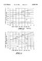
- FIG. 2is a graph depicting the operation of prior art high current drivers.
- FIG. 3is a graph depicting the operation of high current driver providing battery overload protection in accordance with the present invention.
- FIG. 4is an electrical schematic diagram of the high current driver of FIG. 1.
- FIG. 5is an electrical schematic diagram of a high current driver providing battery overload protection in accordance with a second embodiment of the present invention.
- FIG. 6is an expanded electrical schematic diagram of a high current driver of FIG. 5.
- FIG. 7is an electrical schematic diagram of a high current driver providing battery overload protection in accordance with a third embodiment of the present invention.
- FIG. 8is an electrical block diagram of a communication device utilizing the high current driver providing battery overload protection in accordance with the present invention.
- FIG. 1is an electrical block diagram of a high current driver 100 providing battery overload protection in accordance with a first embodiment of the present invention.
- the output of a power control circuit 106is coupled to a first, or bias control input 103 of a differential transconductance amplifier 102, hereinafter referred to as a differential amplifier 102.
- the power control circuit 106controls the consumption of energy by the differential amplifier 102 during active (power on and current supplied) and inactive (power off) states.
- a voltage reference 104is coupled to a second input 105 of the differential amplifier 102 and generates a predetermined reference voltage.
- the voltage reference 104is preferably powered from a second supply voltage (B++) which is generated by a DC--DC converter 124 which is powered from the battery 112.
- B++second supply voltage
- the DC--DC convertertypically generates a 3.1 volt output which is required to supply power to those circuits, such as a microcomputer, which requires a higher supply voltage.
- the output of the DC--DC converteris substantially regulated over the operational range of the battery 112 (from approximately 0.8 volt to 1.6 volts depending upon the particular battery type utilized) so as to provide a more stable voltage output for the voltage reference 104, which in turn improves the accuracy and stability of the predetermined reference voltage generated by the voltage reference 104.
- a first, or positive battery terminal 113 of a battery 112is coupled to a second input 107 of the differential amplifier 102.
- the differential amplifier 102has an output 109 which delivers a drive control signal to an input of a load control element 108.
- the load control element 108has two output terminals, a first output terminal 111 couples to a first terminal of a high current load 110, the other output terminal of the load control element 108 couples to a circuit ground 115.
- a second terminal of the high current load 110also couples to the positive battery terminal 113 of the battery 112.
- the battery 112is shown depicted in FIG. 1 as an ideal battery 114 which has a first battery terminal (the negative battery terminal) which couples to the circuit ground 115.
- a second battery terminal(the positive battery terminal) couples to a first terminal of a resistor 116.
- the second terminal of the resistor 116couples to the positive battery terminal 113.
- the ideal battery 114 and the resistor 116depict schematically a general battery model such as is well known to one of ordinary skill in the art.
- the resistor 116represents the internal cell impedance, the value (magnitude) of which typically varies over the life of a primary battery, such as an alkaline battery, increasing in value as the battery energy is depleted.
- the battery symbolrepresents an ideal battery 114, and the magnitude of the terminal voltage of the ideal battery decreases as energy is consumed.
- Batteriessuch as carbon-zinc batteries or zinc-air batteries, typically have relatively high internal cell impedance's, as compared to an alkaline battery, even for a new battery. As a result, such high impedance batteries are subject to substantial voltage droop when a low impedance, high current load is driven from the battery due to the voltage drop across the internal cell impedance.
- the high current driver 100 shown in FIG. 1operates to provide battery overload protection, and is especially useful with high internal impedance batteries, as described above.
- an external drive request signal 117such as provided by a switch 119 or a controller
- the differential amplifier 102is selectively switched to an active state, supplying a predetermined current to the input of the load control element 108, which is shown as an NPN transistor, although it will be appreciated that the driving current polarity can be inverted such as through the use of a PNP transistor.
- the magnitude of the predetermined current supplied by the differential amplifier 102is controlled, among other things, by the output limiting characteristics of the differential amplifier 102.
- the NPN transistorin turn saturates, supplying current to the high current load 110, the magnitude of the current supplied being dependent upon the resistance of the high current load and the battery terminal voltage.
- the differential amplifier 102is switched to an inactive state, inhibiting the supply of the predetermined current to the input of the load control element 108, which in turn switches the NPN transistor off and inhibits the supply of current to the high current load 110.
- the differential amplifier 102will no longer supply the predetermined current which insures that the NPN transistor is saturated, but rather the magnitude of the current supplied to the input to the load control element 108 is proportionally reduced, being dependent upon the magnitude of the battery terminal voltage relative to the predetermined reference voltage.
- the NPN transistoris no longer supplied sufficient current to remain saturated and moves into the linear region of operation, and as a consequence, the current being drawn by the high current load 110 is reduced.
- the differential amplifier 102thus operates to sense the magnitude of the battery terminal voltage relative to the predetermined reference voltage, and as long as the magnitude of the battery terminal voltage is substantially greater, typically 50 millivolts or more above the predetermined reference voltage, the NPN transistor is saturated.
- the NPN transistorWhen the magnitude of the battery terminal voltage becomes substantially equal to the predetermined reference voltage, typically over a voltage input range of 50 millivolts above and below the predetermined threshold voltage, the NPN transistor operates in the linear region, gradually reducing the magnitude of the current being drawn from the battery, and as a result reducing the voltage droop that would occur as compared to the battery voltage when operating the high current load 110 at the maximum current. It will be appreciated, that when the magnitude of the battery voltage drops to substantially less than the predetermined threshold voltage, the output current of the high current driver 100 would be substantially zero, thereby fully inhibiting the supply of current to the high current load 110. The high current driver 100 is therefor able to maintain the magnitude of the battery terminal voltage within the input voltage range over which proportional control of the current delivered to the high current load is possible.
- FIG. 2is a graph which depicts the operation of a prior art audio transducer driver utilized in a battery operated communication receiver which typically draws by example 100 milli-Amperes (mA) of current from a single cell battery.
- FIG. 3is a graph which depicts the operation of the high current driver 100 in accordance with the present invention which is operated as by example as an audio transducer driver which typically draws 100 milli-Amperes (mA) of current from a single Cell battery.
- the open circuit battery voltageis plotted on the horizontal axis and the loaded battery terminal voltage is plotted on the vertical axis.
- the curve 200illustrates that when the battery 112 is only lightly loaded, the loaded battery terminal voltage tracks substantially the open circuit battery voltage.
- the second curve 202illustrates that for a 100 mA load current, the actual loaded battery terminal voltage is substantially lower than the open circuit battery voltage.
- reliable operationis typically achieved when the loaded battery terminal voltage remains above 1.0 volt.
- this conditionexists only for Open circuit battery voltages above 1.25 volts (204).
- the open circuit battery voltagecan drop to approximately 1.0 volt (206) before the magnitude of the loaded battery terminal voltage drops below 1 volt.
- the third curve 208 in FIG. 2illustrates that the load control element 108 transistor collector voltage remains in saturation down to a loaded battery terminal voltage of 0.8 volts, and then the collector voltage gradually increases as the transistor is operated out of the saturation region.
- the load currentremains substantially constant while the transistor is saturated, and then drops off markedly as the collector voltage increases.
- the transistor which forms the load control element 108remains substantially in saturation as long as the loaded battery terminal voltage remains above about 1.10 volts, and then the collector voltage continues to increase in response to the drop in the loaded battery terminal voltage.
- the loadcurrently gradually drops to 0.0 mA as the loaded battery terminal voltage approaches 1.0 volt. It will be appreciated from FIGS. 2 and 3, and the explanation provided above, that the effective battery life is extended by the high current driver 100 which provides battery overload protection in accordance with the first embodiment of the present invention.
- the high current driver 100 described abovecan be utilized in many applications where battery overload protection would be beneficial for extending the operational life of a battery.
- One such applicationis in a communication receiver, as was described above and will be described in further detail below, where the high current load 110 can be an audible alerting device, such as an electromagnetic transducer, for generating an audible alerting signal; a tactile alerting device, such as a vibrator, for generating a tactile alerting signal; or a visual alerting device, such as an incandescent lamp or LED, for generating a visual alerting signal.
- the external drive request signalis generated from within the communication receiver, as will be described below.
- the high current driver 100can also be utilized to drive a backlighting device, such as an incandescent lamp or other relatively high current illumination device, to provide illumination to a display when the communication device is used in a dark area and a message is displayed.
- a backlighting devicesuch as an incandescent lamp or other relatively high current illumination device
- the external drive request signalis generally provided by a switch 119 (shown in FIG. 1), although it will be appreciated that the external drive request signal can also be generated automatically when the ambient light level sensed is low and a message is being displayed.
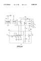
- FIG. 4is an electrical schematic diagram of the high current driver of FIG. 1.
- the high current driver 100includes a differential amplifier 102 which includes a PNP transistor Q1 which has an emitter coupled to a B++supply voltage and four split collectors, One of the split collectors of transistor Q1 ties back to the base, and the remaining three split collectors are coupled together and connect to the emitters of PNP transistors Q5 and Q6.
- the collector of transistor Q5is connected to the base of NPN transistor Q12 which also connects to the base of NPN transistor Q13.
- the collector of transistor Q6is coupled to the collector of transistor Q13 and also to the base of PNP transistor Q15.
- the emitters of transistor Q12 and 13are connected together to ground potential.
- the emitter of transistor Q15couples to the battery voltage (B+), which also couples to the base of transistor Q6.
- the collector of transistor Q12is tied back to the base of transistor Q12.
- Transistors Q12 and Q13form a current mirror, wherein the current sourced by the collector of transistor Q5 is mirrored in the collector of transistor Q13.
- the collector of transistor Q15connects to the input of the load control element 108, and in particular to the base of NPN transistor Q16.
- the emitter of transistor Q16connects to the ground potential, and the collector of transistor Q16 provides the output for the load control element 108, which as previously described connects to the high current load 110.
- Transistors Q15 and Q16form an amplifier for sinking the load current to the high current load 110.
- a resistor R5connects to the base of transistor Q16 and to the circuit ground 115.
- the emitter of a diode connected PNP transistor Q14connects to the battery voltage (B+), and the collector and base of the diode connected transistor Q14 connects to one terminal of resistor R4.
- the other terminal of resistor R4connects to the base of transistor Q15 and to the collectors of transistors Q6 and Q13.
- Transistor Q14 and resistor R4form a leakage control element 120 and together with resistor R5 serve to minimize the effects of amplifier leakage current when the high current driver 100 is switched off.
- the output of the voltage reference 104connects to an input of a buffer amplifier 118 having unity gain.
- the buffer amplifier 118includes PNP transistors Q3 and Q4 which have emitters connected together and to the collector of a split-collector PNP transistor Q2.
- the emitter of transistor Q2connects to a second supply voltage (B++).
- the second supply voltage (B++)is for example typically 3.1 volts and is normally supplied by a step-up DC--DC converter (not shown) which is powered from the battery 112.
- the DC--DC converter outputis substantially regulated over the operational range of the battery 112 (from approximately 0.8 volt to 1.6 volts depending upon the particular battery type utilized) so as to provide a stable voltage to the voltage reference 104, which in turn improves the accuracy and stability of the predetermined reference voltage generated by the voltage reference 104.
- the second collector of transistor Q2connects to the base of transistor Q2 and to the collector of NPN transistor Q9.
- the collector of transistor Q3connects to the collector of NPN transistor Q10 and to the base of NPN transistor Q11.
- the collector of transistor Q4connects to the base of transistor Q4, to the collector of transistor Q11 and to the base of transistor Q5 which is the first input to the differential amplifier 102.
- the emitter of transistor Q10connectors to the emitter of transistor Q9 and to one terminal of a resistor R3.
- the second terminal of resistor R3connects to the ground potential.
- the emitter of transistor Q11also connectors to a ground potential furnished by the circuit ground 115.
- the base of transistor Q10connects to the base of transistor Q9, the base of transistor Q8, the base of transistor Q7 and to one terminal of resistor R1 and to one terminal of resistor R2.
- the second terminal of resistor R1provides the input to the power control circuit 106 which includes transistors Q7, Q8, and Q9.
- the second terminal of resistor R2connects to the ground potential.
- the emitters of transistors Q7 and Q8are connected to the ground potential.
- the collector of transistor Q7connects back to the base of transistor Q7.
- the collector of transistor Q8connects to the base of transistor Q1.
- the collector of transistor Q9connects to the base and one collector of transistor Q2.
- transistor Q6When the supply voltage (B+) is substantially higher than the reference voltage, transistor Q6 is reverse biased. Consequently, when the external drive request signal is supplied to the power control circuit 106, the output current generated by the differential amplifier has a maximum predetermined magnitude, resulting in transistor Q16 being turned on in a saturated condition, supplying a maximum current to the high current load 110 depending upon the load resistance and the supply voltage (B+).
- battery voltage (B+)is compared with the buffered reference voltage by the differential amplifier 102.
- transistor Q6becomes forward biased, and a portion of the current that was being delivered to the base of transistor Q15 is absorbed by transistor Q6, thereby reducing the drive current to transistor Q16, which in turn will eventually pull transistor Q16 out of saturation.
- transistor Q16is pulled out of saturation, the voltage developed across the high current load 110 is reduced, thereby reducing the current which is pulled from the battery 112.
- the feedback arrangement provided by the differential amplifier 102will work to prevent the magnitude of the battery terminal voltage from being drawn below the predetermined threshold voltage established by the voltage reference 104. It will be appreciated that once the battery becomes sufficiently depleted by circuits other than the high current driver 100 circuit in the electronic device, the magnitude of the battery terminal voltage will eventually be drawn below the predetermined threshold voltage established by the voltage reference 104.
- FIG. 5is a simplified electrical schematic diagram of a high current driver 500 providing battery overload protection in accordance with a second embodiment of the present invention.
- a external drive request signal 117couples to the input of power control circuit 106 which is shown as a switched current source 304.
- One terminal of the switched current source 304is coupled to the circuit ground 115, and the output of the switched current source 304 couples to a first, or bias control input 103 of a drive current controller 302.
- a second input 105 of the drive current controller 302couples to the output of a voltage reference 104 which is connected preferably to a second supply voltage (B++), as described above, and which generates a predetermined reference voltage.
- a third input to the drive current controller 302couples to the positive terminal 113 of a battery 112.
- the output 109 of the drive current controller 302couples to the input of a load control element 108, which as shown is an NPN transistor.
- a first output of the load control elementcouples to a first terminal of the high current load 110 while a second output couples to the circuit ground 115.
- the second terminal of the high current load 110is coupled to the positive terminal 113 of the battery 112.
- the drive current controller 302comprises an NPN transistor Q34 and a PNP transistor Q35.
- the collector of transistor Q34couples to the emitter of transistor Q35 and forms the third input of the drive current controller 302 described above and couples to the positive terminal 113 of the battery 112.
- the emitter of transistor Q34couples to the base of transistor Q35 and forms the first input of the drive current controller 302 described above and is coupled to the output of the switched current source 304.
- the base of transistor Q34forms the second input of the drive current controller 302 described above and is coupled to the voltage reference 104.
- the collector of transistor Q35forms the output of the drive current controller 302 described above and couples to the input of the load control element 108.
- V REFis the predetermined reference voltage.
- VBE Q34is the forward biased base to emitter voltage drop of Q34.
- V B+is the battery 112 terminal voltage.
- VBE Q35is the forward biased base to emitter voltage drop of Q35.
- the threshold voltage V THat which the high current driver 500 controls the high current load 110 is then given by:
- VBE Q34is substantially the same as VBE Q35 , as long as the loaded battery terminal voltage is substantially greater than the predetermined threshold voltage V TH , the base-emitter junction of transistor Q34 is reverse biased, and when an external drive request signal 117 is coupled to the input of the switched current source 304, the switched current source 304 provides the base current to turn on transistor Q35. When turned on, transistor Q35 provides full drive current to the load control element 108, which in turn provides power to the high current load 110.
- transistor Q34becomes forward biased, and a portion of the base current previously provided to transistor Q35 is converted to emitter current in transistor Q34, thereby reducing transistor Q35 drive to the load control element 108, and as a result reducing the current provided to the high current load 110, as illustrated in FIG. 3.
- transistor Q35As the loaded battery terminal voltage droops further, significantly more current will be converted to emitter current in transistor Q34, further reducing the base drive provided to transistor Q35, and subsequently further reducing the current provided to the high current load as shown in FIG. 3.
- a significant advantage of the high current driver 500 over the high current driver illustrated in FIG. 4is the improved circuit stability due to having only two active devices in the feedback loop, making the need for a compensation capacitor unlikely.
- the high current driver 500 shown in FIG. 5utilizes the load control element 108 to drive the high current load 110
- the drive current controller 302can, in certain circumstances, directly drive the high current load 110 from the collector of transistor Q35.
- transistor Q35is a discrete transistor, and transistor Q35 is capable of supplying directly the drive current to the high current load 110.
- the terminal of the high current load 110 shown coupled to the battery 112would instead be coupled to the circuit ground 115.
- the load control element 108can be provided by a discrete NPN transistor Q36.
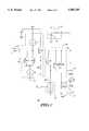
- FIG. 6is an electrical schematic diagram of the high current driver 600 providing battery overload protection in accordance with the second embodiment of the present invention. Only those elements which differ from that shown and described for the high current driver 500 of FIG. 5 will be described in detail below. Unlike that shown in FIG. 5, the output of the voltage reference 104 couples to the input of a buffer amplifier 118, which isolates the voltage reference 104 from the input to the drive current controller 302, thereby further insuring the accuracy and stability of the reference voltage.
- the switched current source 106includes a resistor R1 which at one terminal receives the external drive request signal 117. The other terminal connects to the base terminal of an NPN transistor Q31.
- the collector of transistor Q31is connected back to the base of transistor Q31 and the emitter is connected to the circuit ground 115.
- the base of transistor Q31also couples to the bases of NPN transistors Q32 and Q33.
- the emitters of transistor Q32 and Q33are connected to the circuit ground 115.
- the collector of transistor Q32couples to a bias control input of the buffer amplifier 118 and provides an enable signal to enable and disable operation of the buffer amplifier 118.
- the collector of transistor Q33couples to the emitter of transistor Q34 and the base of transistor Q35.
- Transistors Q32 and Q33operate as current mirrors mirroring the current flowing through the diode connected transistor Q31.
- the input to transistor Q31is low, i.e. coupled to the circuit ground 115, there is no current flowing through transistor Q31, and consequently there is no current mirrored by transistors Q32 and Q33 thereby disabling the buffer amplifier 118 and the drive current controller 302.
- the input to transistor Q31is high, i.e. coupled to the second supply voltage (B++)
- the current flowing through transistor Q31is mirrored by transistors Q32 and Q33 thereby enabling the buffer amplifier 118 and the drive current controller 302.
- the external drive request signalis low, no current is delivered to the high current load and no energy is consumed from the battery 112 by the buffer amplifier 118 or drive current controller 302, which in turn further aids in extending the life of the battery.
- the load control element 108comprises an NPN transistor Q36.
- One terminal of a resistor R3connects to the base of transistor Q36 while the other terminal of resistor R3 connects to the circuit ground 115.
- the output of the drive current controller 302is connected to one terminal of a resistor R2, the other terminal of resistor R2 is connected to the base of transistor Q36.
- Resistor R3sinks any collector base leakage current, thereby preventing transistor Q36 from turning on when the high current driver 600 is turned off.
- Resistor R2limits the magnitude of the base current provided to transistor Q36 in a manner well known to one of ordinary skill in the art.
- the high current driver 700includes a compensation circuit 720 which couples between the voltage reference 104 and the second input to the drive current controller 302.
- the compensation amplifiercomprises a PNP transistor Q37, NPN transistors Q38 and Q40 and two current sources I1 and I2.
- the emitter of transistor Q37couples to the output of the voltage reference 104.
- the collector of transistor Q37connects to the base of transistor Q37, to the emitter of transistor Q38 and to one terminal of current source I1.
- the second terminal of current reference I1connects to the circuit ground 115.
- the collector of transistor Q38couples to the base of transistor Q40 and to one terminal of current source I2.
- the second terminal of current source I2couples to the second supply voltage (B++).
- the base of transistor Q38couples to the emitter of transistor Q40, to the base of transistor Q34 which is the input to the drive current controller 302 as described above, and to one terminal of a resistor R4.
- the second terminal of resistor R4connects to the circuit ground 115.
- the collector of transistor Q40is coupled to the second supply voltage (B++).
- the current source I1has a magnitude twice that of the current reference I2.
- a small portion of the current from current source I2is coupled into the base of transistor Q40 which in turn supplies base current for transistor Q38, transistor Q34 and current through R4. That portion of the current supplied by current source I2 which is not coupled into the base of transistor Q40 flows into the collector of transistor Q38. Since the resultant emitter current of transistor Q38 is approximately one-half of the current that can be sunk by current source I1, the remainder of the I1 current is coupled to the collector of diode-connected transistor Q37 which is then coupled through the emitter of transistor Q37 into the voltage reference 104.
- the threshold voltage, V THin FIG. 7 is given by:
- V REFis the predetermined reference voltage.
- VBE Q34is the forward biased base to emitter voltage drop of Q34.
- VBE Q35is the forward biased base to emitter voltage drop of Q35.
- VBE Q37is the forward biased base to emitter voltage drop of Q37.
- VBE Q38is the forward biased base to emitter voltage drop of Q38.
- the base-emitter voltages of PNP transistors Q35 and Q37will track over process variations and temperature as will the base emitter voltages of NPN transistors Q34 and Q38. Assuming that, at the threshold voltage V TH , the ratio of the emitter currents in transistors Q37 and Q38 are equal to the ratio of the emitter currents in transistors Q35 and Q34, then the differences in the NPN and PNP transistor base-emitter voltages will cancel, and the threshold voltage, V TH , will be approximately equal to V REF .
- the drive current controller 302 of FIG. 7comprises a second PNP transistor Q39.
- the base of transistor Q39connects to the emitter of transistor Q34, the base of transistor Q35, the collector of transistor Q39 and to the output of the switched current source 304.
- the emitter of transistor Q39connects to the emitter of transistor Q35.
- Transistor Q39 in combination with transistor Q35forms a current mirror.
- the emitter area of transistor Q35is selected to be larger than the emitter area of transistor Q39 so that the emitter current of transistor Q35 is much larger than the emitter current of transistor Q39.
- a typical emitter area ratio between Q35 and Q39would be eight.
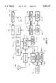
- FIG. 8is an electrical block diagram of a communication receiver 800 utilizing the high current driver 100, 500, 600 or 700 in accordance with the present invention.
- a transmitted selective call messagewhich typically includes an address and a message corresponding thereto, is intercepted by an antenna 802 and is coupled into the input of a receiver 804 which receives and detects the selective call message in a manner well known to one of ordinary skill in the art, providing at the output of the receiver 804 a stream of data corresponding to the detected selective call message.
- the stream of datais coupled to the input of a decoder/controller 806 which processes the data including the selective call message, and when the address received in the selective call message matches an address assigned to the communication receiver 800 which is stored in a code memory 808, the message portion of the selective call message is stored in a message memory 810 for recall at a later time.
- An alert output signalis generated by the decoder/controller 806 which can be directed to a high current driver 814, such as described above, which would drive a high current tactile alerting device 816, alerting silently the user that a message has been received and stored.
- the alert output signalcan also be directed to a high current driver 818, such as described above, which would drive a high current audible alerting device 820, alerting audibly the user that a message has been received and stored.
- the alert outputis reset either automatically after a time-out, or by the user using user controls 812.
- the message stored in the message memory 810is recalled using the user controls 812, whereupon the message is displayed on a display 822, such as an LCD display.
- the communication receiver useractuates a switch 828 which couples to the input of a high current driver 826, such as described above, which in turn supplies power to a lamp 824, thereby providing illumination for reading the message on the display 822.
- the decoder/controller 806when coupled with a photo-detector (not illustrated), can automatically provide illumination to the display 822 by switching on the high current driver 826.
- Poweris supplied to the receiver 804 from a battery 830 via a battery saver switch 834. Operation of the battery saver switch 834 is controlled by the decoder/controller 806 in a manner well known to one of ordinary skill in the art so as to extend the normal life of the battery 830.
- the high current driver 814, 818 and 826which provides battery overload protection in accordance with the present invention, the life of the battery 830 can be further extended, as described above.
- the high current driver 814, 818 and 826also enable the communication receiver 800 to operate effectively, although with shorter battery life, with batteries having high internal impedance, as described above.
- a battery check circuit 832is coupled to the battery and monitors the battery terminal voltage.
- a low battery warning signalis generated which is coupled to the decoder/controller 806, which in turn generates a low battery alert signal which is coupled either to the high current driver 814 which would drive a high current tactile alerting device 816, alerting silently that the battery 830 needs replacement, or to a high current driver 818 which would drive a high current audible alerting device 820, alerting audibly the user that the battery 830 needs replacement.
- the high current driver 814, 818 and 826providing battery overload protection are utilized in combination with a battery check circuit, the communication receiver user is provided with additional time during which a replacement battery must be obtained, before the receiver 804 becomes completely non-operative.
- high current driver circuit 100, 500 and 600have been described above as being coupled to a voltage reference 104, it will be appreciated that when multiple high current driver circuits, such as high current driver 814, 818 and 826 are integrated onto a common semiconductor die, only a single voltage reference is required for the multiple high current driver circuits.
- a DC--DC converter 124which supplies power to those circuit which require a higher supply voltage, and which is also coupled to the high current driver 814, 818 and 826, to provide a voltage source isolated from the battery voltage, as described above.
- the high current driver described abovemonitors the loaded battery terminal voltage, and when the loaded battery terminal voltage falls to a predetermined voltage threshold, the drive current supplied to a high current device, such as an alerting device, or a display illumination device, gradually is reduced. By gradually reducing the drive current to the high current devices, the observed performance of the high current devices is only gradually degraded over time, while the battery life is effectively extended.
- a high current devicesuch as an alerting device, or a display illumination device
- the high current driver in accordance with the present inventionWhen the high current driver in accordance with the present invention is utilized in a battery powered electronic device, such as a laptop computer, a communication receiver, or other electronic device which includes high current load devices as described above, the extension of battery life obtained by providing battery overload protection enables the user to reliably carry out calculations or to receive messages for a greater period of time before the battery must be replaced.
- the high current driver in accordance with the present inventionalso enables the use of batteries having high internal impedance, albeit for shorter periods of time than that obtained from a high quality battery.
Landscapes
- Engineering & Computer Science (AREA)
- Physics & Mathematics (AREA)
- Electromagnetism (AREA)
- General Physics & Mathematics (AREA)
- Power Engineering (AREA)
- Radar, Positioning & Navigation (AREA)
- Automation & Control Theory (AREA)
- Computer Networks & Wireless Communication (AREA)
- Charge And Discharge Circuits For Batteries Or The Like (AREA)
- Continuous-Control Power Sources That Use Transistors (AREA)
Abstract
Description
V.sub.REF -VBE.sub.Q34 >V.sub.B+ -VBE.sub.Q35
V.sub.TH =V.sub.REF -VBE.sub.Q34 +VBE.sub.Q35
V.sub.TH =V.sub.REF -VBE.sub.Q34 +VBE.sub.Q35 +VBE.sub.Q38 -VBE.sub.Q37
Claims (20)
Priority Applications (3)
| Application Number | Priority Date | Filing Date | Title |
|---|---|---|---|
| US08/363,785US5585749A (en) | 1994-12-27 | 1994-12-27 | High current driver providing battery overload protection |
| PCT/US1995/014195WO1996020532A1 (en) | 1994-12-27 | 1995-11-02 | High current driver providing battery overload protection |
| US08/748,641US5744984A (en) | 1994-12-27 | 1996-11-13 | Driver circuit providing controllable battery overload protection |
Applications Claiming Priority (1)
| Application Number | Priority Date | Filing Date | Title |
|---|---|---|---|
| US08/363,785US5585749A (en) | 1994-12-27 | 1994-12-27 | High current driver providing battery overload protection |
Related Child Applications (1)
| Application Number | Title | Priority Date | Filing Date |
|---|---|---|---|
| US08/748,641Continuation-In-PartUS5744984A (en) | 1994-12-27 | 1996-11-13 | Driver circuit providing controllable battery overload protection |
Publications (1)
| Publication Number | Publication Date |
|---|---|
| US5585749Atrue US5585749A (en) | 1996-12-17 |
Family
ID=23431724
Family Applications (2)
| Application Number | Title | Priority Date | Filing Date |
|---|---|---|---|
| US08/363,785Expired - LifetimeUS5585749A (en) | 1994-12-27 | 1994-12-27 | High current driver providing battery overload protection |
| US08/748,641Expired - LifetimeUS5744984A (en) | 1994-12-27 | 1996-11-13 | Driver circuit providing controllable battery overload protection |
Family Applications After (1)
| Application Number | Title | Priority Date | Filing Date |
|---|---|---|---|
| US08/748,641Expired - LifetimeUS5744984A (en) | 1994-12-27 | 1996-11-13 | Driver circuit providing controllable battery overload protection |
Country Status (2)
| Country | Link |
|---|---|
| US (2) | US5585749A (en) |
| WO (1) | WO1996020532A1 (en) |
Cited By (79)
| Publication number | Priority date | Publication date | Assignee | Title |
|---|---|---|---|---|
| US5804958A (en)* | 1997-06-13 | 1998-09-08 | Motorola, Inc. | Self-referenced control circuit |
| US5970254A (en)* | 1997-06-27 | 1999-10-19 | Cooke; Laurence H. | Integrated processor and programmable data path chip for reconfigurable computing |
| US5994878A (en)* | 1997-09-30 | 1999-11-30 | Chartec Laboratories A/S | Method and apparatus for charging a rechargeable battery |
| US6107985A (en)* | 1997-10-30 | 2000-08-22 | Ericsson Inc. | Backlighting circuits including brownout detection circuits responsive to a current through at least one light emitting diode and related methods |
| US6246215B1 (en) | 1999-03-08 | 2001-06-12 | O2 Micro International Limited | Buffer battery power supply system |
| US20020075968A1 (en)* | 1999-10-19 | 2002-06-20 | Jared Zerbe | Method and apparatus for generating multi-level reference voltage in systems using equalization or crosstalk cancellation |
| US6590370B1 (en)* | 2002-10-01 | 2003-07-08 | Mti Microfuel Cells Inc. | Switching DC-DC power converter and battery charger for use with direct oxidation fuel cell power source |
| US6680604B2 (en) | 2000-03-27 | 2004-01-20 | Intersil Corporation | Methods to control the droop when powering dual mode processors and associated circuits |
| US20050057189A1 (en)* | 2003-05-14 | 2005-03-17 | Hajime Kimura | Semiconductor device |
| US20050092617A1 (en)* | 2003-11-03 | 2005-05-05 | Lecky John E. | Automatic measurement of fuel cell resistance |
| US20050110453A1 (en)* | 2003-11-21 | 2005-05-26 | Lecky John E. | Dynamic fuel cell system management controller |
| US20050162206A1 (en)* | 2003-04-25 | 2005-07-28 | Hajime Kimura | Semiconductor device |
| US20050168905A1 (en)* | 2003-06-06 | 2005-08-04 | Hajime Kimura | Semiconductor device |
| US7093145B2 (en) | 1999-10-19 | 2006-08-15 | Rambus Inc. | Method and apparatus for calibrating a multi-level current mode driver having a plurality of source calibration signals |
| US20070036286A1 (en)* | 2005-08-08 | 2007-02-15 | David Champlin | Method and device for enabling message responses to incoming phone calls |
| DE102004034864B4 (en)* | 2003-11-07 | 2007-05-24 | Hewlett-Packard Development Co., L.P., Houston | Products and methods for dynamically changing a clock signal |
| US20070257789A1 (en)* | 2006-03-02 | 2007-11-08 | Preco Electronics, Inc. | Adjusting Alarm Drive Pulse for Changes in Temperature and Supply Voltage Via Microcontroller |
| US20070285048A1 (en)* | 2006-06-12 | 2007-12-13 | Leach David H | Fuel cell charger interface with multiple voltage outputs for portable devices |
| US20080136655A1 (en)* | 2006-12-12 | 2008-06-12 | Inventec Appliances Corp. | Over-current alerting circuit and method thereof |
| US20090061833A1 (en)* | 2007-08-30 | 2009-03-05 | Junius Ho | System, method and device to use messaging to implement programmatic actions |
| US20090085612A1 (en)* | 2007-10-01 | 2009-04-02 | Smith Gregory H | Multi-purpose current driver system and method |
| US7800482B1 (en)* | 2006-07-25 | 2010-09-21 | Costin Darryl J | High intensity small size personal alarm |
| US20100309692A1 (en)* | 2006-01-13 | 2010-12-09 | Lesley Chisenga | Power conditioning units |
| US8369113B2 (en) | 2004-11-08 | 2013-02-05 | Enecsys Limited | Power conditioning unit |
| US8461809B2 (en) | 2006-01-13 | 2013-06-11 | Enecsys Limited | Power conditioning unit |
| US8538478B2 (en) | 2001-06-11 | 2013-09-17 | Palm, Inc. | Integrated personal digital assistant device |
| US8674668B2 (en) | 2010-06-07 | 2014-03-18 | Enecsys Limited | Solar photovoltaic systems |
| US8861667B1 (en) | 2002-07-12 | 2014-10-14 | Rambus Inc. | Clock data recovery circuit with equalizer clock calibration |
| US8976108B2 (en) | 2001-06-11 | 2015-03-10 | Qualcomm Incorporated | Interface for processing of an alternate symbol in a computer device |
| US9112379B2 (en) | 2006-12-06 | 2015-08-18 | Solaredge Technologies Ltd. | Pairing of components in a direct current distributed power generation system |
| US9130401B2 (en) | 2006-12-06 | 2015-09-08 | Solaredge Technologies Ltd. | Distributed power harvesting systems using DC power sources |
| US9235228B2 (en) | 2012-03-05 | 2016-01-12 | Solaredge Technologies Ltd. | Direct current link circuit |
| US9291696B2 (en) | 2007-12-05 | 2016-03-22 | Solaredge Technologies Ltd. | Photovoltaic system power tracking method |
| US9318974B2 (en) | 2014-03-26 | 2016-04-19 | Solaredge Technologies Ltd. | Multi-level inverter with flying capacitor topology |
| US9362743B2 (en) | 2008-05-05 | 2016-06-07 | Solaredge Technologies Ltd. | Direct current power combiner |
| US9368964B2 (en) | 2006-12-06 | 2016-06-14 | Solaredge Technologies Ltd. | Distributed power system using direct current power sources |
| US9401599B2 (en) | 2010-12-09 | 2016-07-26 | Solaredge Technologies Ltd. | Disconnection of a string carrying direct current power |
| US9407161B2 (en) | 2007-12-05 | 2016-08-02 | Solaredge Technologies Ltd. | Parallel connected inverters |
| US9537445B2 (en) | 2008-12-04 | 2017-01-03 | Solaredge Technologies Ltd. | Testing of a photovoltaic panel |
| US9543889B2 (en) | 2006-12-06 | 2017-01-10 | Solaredge Technologies Ltd. | Distributed power harvesting systems using DC power sources |
| US9548619B2 (en) | 2013-03-14 | 2017-01-17 | Solaredge Technologies Ltd. | Method and apparatus for storing and depleting energy |
| US9590526B2 (en) | 2006-12-06 | 2017-03-07 | Solaredge Technologies Ltd. | Safety mechanisms, wake up and shutdown methods in distributed power installations |
| US9647442B2 (en) | 2010-11-09 | 2017-05-09 | Solaredge Technologies Ltd. | Arc detection and prevention in a power generation system |
| US9644993B2 (en) | 2006-12-06 | 2017-05-09 | Solaredge Technologies Ltd. | Monitoring of distributed power harvesting systems using DC power sources |
| US9673711B2 (en) | 2007-08-06 | 2017-06-06 | Solaredge Technologies Ltd. | Digital average input current control in power converter |
| US9680304B2 (en) | 2006-12-06 | 2017-06-13 | Solaredge Technologies Ltd. | Method for distributed power harvesting using DC power sources |
| US9812984B2 (en) | 2012-01-30 | 2017-11-07 | Solaredge Technologies Ltd. | Maximizing power in a photovoltaic distributed power system |
| US9819178B2 (en) | 2013-03-15 | 2017-11-14 | Solaredge Technologies Ltd. | Bypass mechanism |
| US9831824B2 (en) | 2007-12-05 | 2017-11-28 | SolareEdge Technologies Ltd. | Current sensing on a MOSFET |
| US9853538B2 (en) | 2007-12-04 | 2017-12-26 | Solaredge Technologies Ltd. | Distributed power harvesting systems using DC power sources |
| US9853565B2 (en) | 2012-01-30 | 2017-12-26 | Solaredge Technologies Ltd. | Maximized power in a photovoltaic distributed power system |
| US9866098B2 (en) | 2011-01-12 | 2018-01-09 | Solaredge Technologies Ltd. | Serially connected inverters |
| US9869701B2 (en) | 2009-05-26 | 2018-01-16 | Solaredge Technologies Ltd. | Theft detection and prevention in a power generation system |
| US9876430B2 (en) | 2008-03-24 | 2018-01-23 | Solaredge Technologies Ltd. | Zero voltage switching |
| US9923516B2 (en) | 2012-01-30 | 2018-03-20 | Solaredge Technologies Ltd. | Photovoltaic panel circuitry |
| US9941813B2 (en) | 2013-03-14 | 2018-04-10 | Solaredge Technologies Ltd. | High frequency multi-level inverter |
| US9960667B2 (en) | 2006-12-06 | 2018-05-01 | Solaredge Technologies Ltd. | System and method for protection during inverter shutdown in distributed power installations |
| US9966766B2 (en) | 2006-12-06 | 2018-05-08 | Solaredge Technologies Ltd. | Battery power delivery module |
| US10115841B2 (en) | 2012-06-04 | 2018-10-30 | Solaredge Technologies Ltd. | Integrated photovoltaic panel circuitry |
| US10230310B2 (en) | 2016-04-05 | 2019-03-12 | Solaredge Technologies Ltd | Safety switch for photovoltaic systems |
| US10396662B2 (en) | 2011-09-12 | 2019-08-27 | Solaredge Technologies Ltd | Direct current link circuit |
| US10673222B2 (en) | 2010-11-09 | 2020-06-02 | Solaredge Technologies Ltd. | Arc detection and prevention in a power generation system |
| US10673229B2 (en) | 2010-11-09 | 2020-06-02 | Solaredge Technologies Ltd. | Arc detection and prevention in a power generation system |
| US10931119B2 (en) | 2012-01-11 | 2021-02-23 | Solaredge Technologies Ltd. | Photovoltaic module |
| US11018623B2 (en) | 2016-04-05 | 2021-05-25 | Solaredge Technologies Ltd. | Safety switch for photovoltaic systems |
| US11177663B2 (en) | 2016-04-05 | 2021-11-16 | Solaredge Technologies Ltd. | Chain of power devices |
| US11264947B2 (en) | 2007-12-05 | 2022-03-01 | Solaredge Technologies Ltd. | Testing of a photovoltaic panel |
| US11296650B2 (en) | 2006-12-06 | 2022-04-05 | Solaredge Technologies Ltd. | System and method for protection during inverter shutdown in distributed power installations |
| US11309832B2 (en) | 2006-12-06 | 2022-04-19 | Solaredge Technologies Ltd. | Distributed power harvesting systems using DC power sources |
| US11569659B2 (en) | 2006-12-06 | 2023-01-31 | Solaredge Technologies Ltd. | Distributed power harvesting systems using DC power sources |
| US11569660B2 (en) | 2006-12-06 | 2023-01-31 | Solaredge Technologies Ltd. | Distributed power harvesting systems using DC power sources |
| US11687112B2 (en) | 2006-12-06 | 2023-06-27 | Solaredge Technologies Ltd. | Distributed power harvesting systems using DC power sources |
| US11728768B2 (en) | 2006-12-06 | 2023-08-15 | Solaredge Technologies Ltd. | Pairing of components in a direct current distributed power generation system |
| US11735910B2 (en) | 2006-12-06 | 2023-08-22 | Solaredge Technologies Ltd. | Distributed power system using direct current power sources |
| US11855231B2 (en) | 2006-12-06 | 2023-12-26 | Solaredge Technologies Ltd. | Distributed power harvesting systems using DC power sources |
| US11881814B2 (en) | 2005-12-05 | 2024-01-23 | Solaredge Technologies Ltd. | Testing of a photovoltaic panel |
| US11888387B2 (en) | 2006-12-06 | 2024-01-30 | Solaredge Technologies Ltd. | Safety mechanisms, wake up and shutdown methods in distributed power installations |
| US12057807B2 (en) | 2016-04-05 | 2024-08-06 | Solaredge Technologies Ltd. | Chain of power devices |
| US12418177B2 (en) | 2009-10-24 | 2025-09-16 | Solaredge Technologies Ltd. | Distributed power system using direct current power sources |
Families Citing this family (16)
| Publication number | Priority date | Publication date | Assignee | Title |
|---|---|---|---|---|
| KR0162835B1 (en)* | 1995-12-30 | 1998-12-01 | 김광호 | Portable wireless terminal with vibration realization circuit |
| JPH1013897A (en)* | 1996-06-27 | 1998-01-16 | Nec Shizuoka Ltd | Selective radio call receiver with display |
| JP3165053B2 (en)* | 1997-01-30 | 2001-05-14 | 日本電気アイシーマイコンシステム株式会社 | Integrator circuit |
| JP3805543B2 (en)* | 1998-11-19 | 2006-08-02 | 三菱電機株式会社 | Semiconductor integrated circuit |
| US6373256B1 (en)* | 1999-01-08 | 2002-04-16 | Fairchild Semiconductor Corporation | Programmable low battery detector |
| US6392473B1 (en) | 2000-01-11 | 2002-05-21 | Visteon Global Tech., Inc. | Voltage protection and biasing circuit |
| DE10052374A1 (en)* | 2000-10-20 | 2002-05-02 | Braun Gmbh | Small electrical appliance with an accumulator and a consumer |
| DE10110140C1 (en)* | 2001-03-02 | 2003-02-06 | Infineon Technologies Ag | Overload protection circuit for line drivers |
| US6867604B2 (en)* | 2002-06-28 | 2005-03-15 | International Business Machines Corporation | Apparatus for accurately measuring battery voltage |
| CN1295873C (en)* | 2003-08-05 | 2007-01-17 | 华邦电子股份有限公司 | A drive circuit that can dynamically adjust the output current and limit the input current |
| US7151433B2 (en)* | 2003-08-05 | 2006-12-19 | Chun James K | Combination LED flashlight and garage door transmitter |
| US7323793B2 (en)* | 2003-12-19 | 2008-01-29 | Texas Instruments Incorporated | System and method for driving one or more loads |
| JP4308158B2 (en)* | 2004-03-30 | 2009-08-05 | ローム株式会社 | Boost control device and electronic device using the same |
| US7224153B2 (en)* | 2005-04-26 | 2007-05-29 | Texas Instruments Incorporated | Apparatus and method to compensate for effects of load capacitance on power regulator |
| TWI383167B (en)* | 2008-09-23 | 2013-01-21 | Wistron Corp | Method for detecting operations of a power storage device and related power storage device |
| CN102257451B (en)* | 2008-12-16 | 2014-07-09 | 意法爱立信有限公司 | Circuit system and method of controlling power management |
Citations (10)
| Publication number | Priority date | Publication date | Assignee | Title |
|---|---|---|---|---|
| US3810006A (en)* | 1972-06-16 | 1974-05-07 | Centre Electron Horloger | Current comparing device |
| US4107596A (en)* | 1976-10-21 | 1978-08-15 | The Singer Company | Efficient bidirectional power converter for portable data gathering apparatus |
| US4221979A (en)* | 1977-12-08 | 1980-09-09 | Rca Corporation | Non-inverting buffer circuits |
| US4396889A (en)* | 1979-12-22 | 1983-08-02 | Kabushiki Kaisha Daini Seikosha | Nonadjusting battery life detector |
| US4631737A (en)* | 1984-12-06 | 1986-12-23 | Motorola, Inc. | Self biasing direct coupled data limiter |
| US4847520A (en)* | 1987-08-31 | 1989-07-11 | Linear Technology Corporation | Fast PNP transistor turn-off circuit |
| US5128553A (en)* | 1990-06-22 | 1992-07-07 | Linear Technology Corporation | Lateral PNP turn-off drive circuit |
| US5357188A (en)* | 1991-07-25 | 1994-10-18 | Rohm Co., Ltd. | Current mirror circuit operable with a low power supply voltage |
| US5412336A (en)* | 1993-11-10 | 1995-05-02 | Motorola, Inc. | Self-biasing boot-strapped cascode amplifier |
| US5430439A (en)* | 1991-03-04 | 1995-07-04 | Motorola, Inc. | Selective call receiver having user defined message information in memory and presentation methods thereof |
Family Cites Families (1)
| Publication number | Priority date | Publication date | Assignee | Title |
|---|---|---|---|---|
| US5095308A (en)* | 1990-01-09 | 1992-03-10 | Southern Marine Research, Inc. | Transceiver with battery saver and method of using same |
- 1994
- 1994-12-27USUS08/363,785patent/US5585749A/ennot_activeExpired - Lifetime
- 1995
- 1995-11-02WOPCT/US1995/014195patent/WO1996020532A1/enactiveSearch and Examination
- 1996
- 1996-11-13USUS08/748,641patent/US5744984A/ennot_activeExpired - Lifetime
Patent Citations (10)
| Publication number | Priority date | Publication date | Assignee | Title |
|---|---|---|---|---|
| US3810006A (en)* | 1972-06-16 | 1974-05-07 | Centre Electron Horloger | Current comparing device |
| US4107596A (en)* | 1976-10-21 | 1978-08-15 | The Singer Company | Efficient bidirectional power converter for portable data gathering apparatus |
| US4221979A (en)* | 1977-12-08 | 1980-09-09 | Rca Corporation | Non-inverting buffer circuits |
| US4396889A (en)* | 1979-12-22 | 1983-08-02 | Kabushiki Kaisha Daini Seikosha | Nonadjusting battery life detector |
| US4631737A (en)* | 1984-12-06 | 1986-12-23 | Motorola, Inc. | Self biasing direct coupled data limiter |
| US4847520A (en)* | 1987-08-31 | 1989-07-11 | Linear Technology Corporation | Fast PNP transistor turn-off circuit |
| US5128553A (en)* | 1990-06-22 | 1992-07-07 | Linear Technology Corporation | Lateral PNP turn-off drive circuit |
| US5430439A (en)* | 1991-03-04 | 1995-07-04 | Motorola, Inc. | Selective call receiver having user defined message information in memory and presentation methods thereof |
| US5357188A (en)* | 1991-07-25 | 1994-10-18 | Rohm Co., Ltd. | Current mirror circuit operable with a low power supply voltage |
| US5412336A (en)* | 1993-11-10 | 1995-05-02 | Motorola, Inc. | Self-biasing boot-strapped cascode amplifier |
Cited By (219)
| Publication number | Priority date | Publication date | Assignee | Title |
|---|---|---|---|---|
| US5804958A (en)* | 1997-06-13 | 1998-09-08 | Motorola, Inc. | Self-referenced control circuit |
| US5970254A (en)* | 1997-06-27 | 1999-10-19 | Cooke; Laurence H. | Integrated processor and programmable data path chip for reconfigurable computing |
| US5994878A (en)* | 1997-09-30 | 1999-11-30 | Chartec Laboratories A/S | Method and apparatus for charging a rechargeable battery |
| US6107985A (en)* | 1997-10-30 | 2000-08-22 | Ericsson Inc. | Backlighting circuits including brownout detection circuits responsive to a current through at least one light emitting diode and related methods |
| US6256007B1 (en) | 1997-10-30 | 2001-07-03 | Ericsson Inc. | Radio communications devices with backlighting circuits having brownout detection circuits responsive to a current through a light emitting diode |
| US6246215B1 (en) | 1999-03-08 | 2001-06-12 | O2 Micro International Limited | Buffer battery power supply system |
| US9998305B2 (en) | 1999-10-19 | 2018-06-12 | Rambus Inc. | Multi-PAM output driver with distortion compensation |
| US7859436B2 (en) | 1999-10-19 | 2010-12-28 | Rambus Inc. | Memory device receiver |
| US7072415B2 (en)* | 1999-10-19 | 2006-07-04 | Rambus Inc. | Method and apparatus for generating multi-level reference voltage in systems using equalization or crosstalk cancellation |
| US20020075968A1 (en)* | 1999-10-19 | 2002-06-20 | Jared Zerbe | Method and apparatus for generating multi-level reference voltage in systems using equalization or crosstalk cancellation |
| US7456778B2 (en) | 1999-10-19 | 2008-11-25 | Rambus Inc. | Method and apparatus for calibrating a multi-level current mode driver having a plurality of source calibration signals |
| US8320494B2 (en) | 1999-10-19 | 2012-11-27 | Rambus Inc. | Method and apparatus for generating reference voltage to adjust for attenuation |
| US8634452B2 (en) | 1999-10-19 | 2014-01-21 | Rambus Inc. | Multiphase receiver with equalization circuitry |
| US9544169B2 (en) | 1999-10-19 | 2017-01-10 | Rambus Inc. | Multiphase receiver with equalization circuitry |
| US20060233278A1 (en)* | 1999-10-19 | 2006-10-19 | Rambus Inc. | Method and apparatus for generating multi-level reference voltage in systems using equalization or crosstalk cancellation |
| US7093145B2 (en) | 1999-10-19 | 2006-08-15 | Rambus Inc. | Method and apparatus for calibrating a multi-level current mode driver having a plurality of source calibration signals |
| US20040090217A1 (en)* | 2000-03-27 | 2004-05-13 | Intersil Corporation | Methods to control the droop when powering dual mode processors and associated circuits |
| US6919715B2 (en) | 2000-03-27 | 2005-07-19 | Intersil Corporation | Methods to control the droop when powering dual mode processors and associated circuits |
| US6680604B2 (en) | 2000-03-27 | 2004-01-20 | Intersil Corporation | Methods to control the droop when powering dual mode processors and associated circuits |
| US9549056B2 (en) | 2001-06-11 | 2017-01-17 | Qualcomm Incorporated | Integrated personal digital assistant device |
| US10326871B2 (en) | 2001-06-11 | 2019-06-18 | Qualcomm Incorporated | Integrated personal digital assistant device |
| US8976108B2 (en) | 2001-06-11 | 2015-03-10 | Qualcomm Incorporated | Interface for processing of an alternate symbol in a computer device |
| US9203940B2 (en) | 2001-06-11 | 2015-12-01 | Qualcomm Incorporated | Integrated personal digital assistant device |
| US8538478B2 (en) | 2001-06-11 | 2013-09-17 | Palm, Inc. | Integrated personal digital assistant device |
| US10097679B2 (en) | 2001-06-11 | 2018-10-09 | Qualcomm Incorporated | Integrated personal digital assistant device |
| US9696905B2 (en) | 2001-06-11 | 2017-07-04 | Qualcomm Incorporated | Interface for processing of an alternate symbol in a computer device |
| US8861667B1 (en) | 2002-07-12 | 2014-10-14 | Rambus Inc. | Clock data recovery circuit with equalizer clock calibration |
| US6590370B1 (en)* | 2002-10-01 | 2003-07-08 | Mti Microfuel Cells Inc. | Switching DC-DC power converter and battery charger for use with direct oxidation fuel cell power source |
| US20050162206A1 (en)* | 2003-04-25 | 2005-07-28 | Hajime Kimura | Semiconductor device |
| US20050057189A1 (en)* | 2003-05-14 | 2005-03-17 | Hajime Kimura | Semiconductor device |
| US7463223B2 (en) | 2003-05-14 | 2008-12-09 | Semiconductor Energy Laboratory Co., Ltd. | Semiconductor device |
| US9576526B2 (en) | 2003-05-14 | 2017-02-21 | Semiconductor Energy Laboratory Co., Ltd. | Semiconductor device |
| US8289238B2 (en) | 2003-05-14 | 2012-10-16 | Semiconductor Energy Laboratory Co., Ltd. | Semiconductor device |
| US20110133828A1 (en)* | 2003-06-06 | 2011-06-09 | Semiconductor Energy Laboratory Co., Ltd. | Semiconductor Device |
| US20050168905A1 (en)* | 2003-06-06 | 2005-08-04 | Hajime Kimura | Semiconductor device |
| US8284128B2 (en) | 2003-06-06 | 2012-10-09 | Semiconductor Energy Laboratory Co., Ltd. | Semiconductor device |
| US7852330B2 (en) | 2003-06-06 | 2010-12-14 | Semiconductor Energy Laboratory Co., Ltd. | Semiconductor device |
| US20050092617A1 (en)* | 2003-11-03 | 2005-05-05 | Lecky John E. | Automatic measurement of fuel cell resistance |
| US7270900B2 (en) | 2003-11-03 | 2007-09-18 | Mti Microfuel Cells, Inc. | Automatic measurement of fuel cell resistance |
| DE102004034864B4 (en)* | 2003-11-07 | 2007-05-24 | Hewlett-Packard Development Co., L.P., Houston | Products and methods for dynamically changing a clock signal |
| US7362073B2 (en) | 2003-11-21 | 2008-04-22 | Mti Microfuel Cells, Inc. | Dynamic fuel cell system management controller |
| US20050110453A1 (en)* | 2003-11-21 | 2005-05-26 | Lecky John E. | Dynamic fuel cell system management controller |
| US10033292B2 (en) | 2004-11-08 | 2018-07-24 | Solarcity Corporation | Power conditioning unit with voltage converters |
| US9831794B2 (en) | 2004-11-08 | 2017-11-28 | Solarcity Corporation | Power conditioning unit with voltage converters |
| US8971082B2 (en) | 2004-11-08 | 2015-03-03 | Enecsys Limited | Power conditioning unit with voltage converters |
| US8369113B2 (en) | 2004-11-08 | 2013-02-05 | Enecsys Limited | Power conditioning unit |
| US9473038B2 (en) | 2004-11-08 | 2016-10-18 | Solarcity Corporation | Power conditioning unit with voltage converters |
| US8737578B2 (en) | 2005-08-08 | 2014-05-27 | Qualcomm Incorporated | Method and device for enabling message responses to incoming phone calls |
| US7844037B2 (en)* | 2005-08-08 | 2010-11-30 | Palm, Inc. | Method and device for enabling message responses to incoming phone calls |
| US20070036286A1 (en)* | 2005-08-08 | 2007-02-15 | David Champlin | Method and device for enabling message responses to incoming phone calls |
| US8311189B2 (en) | 2005-08-08 | 2012-11-13 | Hewlett-Packard Development Company, L.P. | Method and device for enabling message responses to incoming phone calls |
| US20110028168A1 (en)* | 2005-08-08 | 2011-02-03 | David Champlin | Method and device for enabling message responses to incoming phone calls |
| US11881814B2 (en) | 2005-12-05 | 2024-01-23 | Solaredge Technologies Ltd. | Testing of a photovoltaic panel |
| US9812980B2 (en) | 2006-01-13 | 2017-11-07 | Solarcity Corporation | Power conditioning units |
| US20100309692A1 (en)* | 2006-01-13 | 2010-12-09 | Lesley Chisenga | Power conditioning units |
| US10193467B2 (en) | 2006-01-13 | 2019-01-29 | Tesla, Inc. | Power conditioning units |
| US9246397B2 (en) | 2006-01-13 | 2016-01-26 | Solarcity Corporation | Solar power conditioning unit |
| US9270191B2 (en) | 2006-01-13 | 2016-02-23 | Solarcity Corporation | Power condition units with MPPT |
| US9812985B2 (en) | 2006-01-13 | 2017-11-07 | Solarcity Corporation | Solar power conditioning unit |
| US8461809B2 (en) | 2006-01-13 | 2013-06-11 | Enecsys Limited | Power conditioning unit |
| US8405367B2 (en) | 2006-01-13 | 2013-03-26 | Enecsys Limited | Power conditioning units |
| US8811047B2 (en)* | 2006-01-13 | 2014-08-19 | Enecsys Limited | Solar power conditioning unit |
| US20070257789A1 (en)* | 2006-03-02 | 2007-11-08 | Preco Electronics, Inc. | Adjusting Alarm Drive Pulse for Changes in Temperature and Supply Voltage Via Microcontroller |
| US20070285048A1 (en)* | 2006-06-12 | 2007-12-13 | Leach David H | Fuel cell charger interface with multiple voltage outputs for portable devices |
| US7800482B1 (en)* | 2006-07-25 | 2010-09-21 | Costin Darryl J | High intensity small size personal alarm |
| US10230245B2 (en) | 2006-12-06 | 2019-03-12 | Solaredge Technologies Ltd | Battery power delivery module |
| US9960667B2 (en) | 2006-12-06 | 2018-05-01 | Solaredge Technologies Ltd. | System and method for protection during inverter shutdown in distributed power installations |
| US12388492B2 (en) | 2006-12-06 | 2025-08-12 | Solaredge Technologies Ltd. | Safety mechanisms, wake up and shutdown methods in distributed power installations |
| US12316274B2 (en) | 2006-12-06 | 2025-05-27 | Solaredge Technologies Ltd. | Pairing of components in a direct current distributed power generation system |
| US9543889B2 (en) | 2006-12-06 | 2017-01-10 | Solaredge Technologies Ltd. | Distributed power harvesting systems using DC power sources |
| US12281919B2 (en) | 2006-12-06 | 2025-04-22 | Solaredge Technologies Ltd. | Monitoring of distributed power harvesting systems using DC power sources |
| US12276997B2 (en) | 2006-12-06 | 2025-04-15 | Solaredge Technologies Ltd. | Distributed power harvesting systems using DC power sources |
| US9368964B2 (en) | 2006-12-06 | 2016-06-14 | Solaredge Technologies Ltd. | Distributed power system using direct current power sources |
| US9590526B2 (en) | 2006-12-06 | 2017-03-07 | Solaredge Technologies Ltd. | Safety mechanisms, wake up and shutdown methods in distributed power installations |
| US12224706B2 (en) | 2006-12-06 | 2025-02-11 | Solaredge Technologies Ltd. | Pairing of components in a direct current distributed power generation system |
| US12107417B2 (en) | 2006-12-06 | 2024-10-01 | Solaredge Technologies Ltd. | Distributed power harvesting systems using DC power sources |
| US9644993B2 (en) | 2006-12-06 | 2017-05-09 | Solaredge Technologies Ltd. | Monitoring of distributed power harvesting systems using DC power sources |
| US11031861B2 (en) | 2006-12-06 | 2021-06-08 | Solaredge Technologies Ltd. | System and method for protection during inverter shutdown in distributed power installations |
| US9680304B2 (en) | 2006-12-06 | 2017-06-13 | Solaredge Technologies Ltd. | Method for distributed power harvesting using DC power sources |
| US12068599B2 (en) | 2006-12-06 | 2024-08-20 | Solaredge Technologies Ltd. | System and method for protection during inverter shutdown in distributed power installations |
| US12046940B2 (en) | 2006-12-06 | 2024-07-23 | Solaredge Technologies Ltd. | Battery power control |
| US12032080B2 (en) | 2006-12-06 | 2024-07-09 | Solaredge Technologies Ltd. | Safety mechanisms, wake up and shutdown methods in distributed power installations |
| US12027849B2 (en) | 2006-12-06 | 2024-07-02 | Solaredge Technologies Ltd. | Distributed power system using direct current power sources |
| US12027970B2 (en) | 2006-12-06 | 2024-07-02 | Solaredge Technologies Ltd. | Safety mechanisms, wake up and shutdown methods in distributed power installations |
| US11962243B2 (en) | 2006-12-06 | 2024-04-16 | Solaredge Technologies Ltd. | Method for distributed power harvesting using DC power sources |
| US11961922B2 (en) | 2006-12-06 | 2024-04-16 | Solaredge Technologies Ltd. | Distributed power harvesting systems using DC power sources |
| US11043820B2 (en) | 2006-12-06 | 2021-06-22 | Solaredge Technologies Ltd. | Battery power delivery module |
| US11888387B2 (en) | 2006-12-06 | 2024-01-30 | Solaredge Technologies Ltd. | Safety mechanisms, wake up and shutdown methods in distributed power installations |
| US9853490B2 (en) | 2006-12-06 | 2017-12-26 | Solaredge Technologies Ltd. | Distributed power system using direct current power sources |
| US11063440B2 (en) | 2006-12-06 | 2021-07-13 | Solaredge Technologies Ltd. | Method for distributed power harvesting using DC power sources |
| US11855231B2 (en) | 2006-12-06 | 2023-12-26 | Solaredge Technologies Ltd. | Distributed power harvesting systems using DC power sources |
| US11735910B2 (en) | 2006-12-06 | 2023-08-22 | Solaredge Technologies Ltd. | Distributed power system using direct current power sources |
| US11728768B2 (en) | 2006-12-06 | 2023-08-15 | Solaredge Technologies Ltd. | Pairing of components in a direct current distributed power generation system |
| US11687112B2 (en) | 2006-12-06 | 2023-06-27 | Solaredge Technologies Ltd. | Distributed power harvesting systems using DC power sources |
| US11682918B2 (en) | 2006-12-06 | 2023-06-20 | Solaredge Technologies Ltd. | Battery power delivery module |
| US9948233B2 (en) | 2006-12-06 | 2018-04-17 | Solaredge Technologies Ltd. | Distributed power harvesting systems using DC power sources |
| US11002774B2 (en) | 2006-12-06 | 2021-05-11 | Solaredge Technologies Ltd. | Monitoring of distributed power harvesting systems using DC power sources |
| US9960731B2 (en) | 2006-12-06 | 2018-05-01 | Solaredge Technologies Ltd. | Pairing of components in a direct current distributed power generation system |
| US9966766B2 (en) | 2006-12-06 | 2018-05-08 | Solaredge Technologies Ltd. | Battery power delivery module |
| US11658482B2 (en) | 2006-12-06 | 2023-05-23 | Solaredge Technologies Ltd. | Distributed power harvesting systems using DC power sources |
| US9130401B2 (en) | 2006-12-06 | 2015-09-08 | Solaredge Technologies Ltd. | Distributed power harvesting systems using DC power sources |
| US11598652B2 (en) | 2006-12-06 | 2023-03-07 | Solaredge Technologies Ltd. | Monitoring of distributed power harvesting systems using DC power sources |
| US9112379B2 (en) | 2006-12-06 | 2015-08-18 | Solaredge Technologies Ltd. | Pairing of components in a direct current distributed power generation system |
| US11594881B2 (en) | 2006-12-06 | 2023-02-28 | Solaredge Technologies Ltd. | Distributed power harvesting systems using DC power sources |
| US10097007B2 (en) | 2006-12-06 | 2018-10-09 | Solaredge Technologies Ltd. | Method for distributed power harvesting using DC power sources |
| US11073543B2 (en) | 2006-12-06 | 2021-07-27 | Solaredge Technologies Ltd. | Monitoring of distributed power harvesting systems using DC power sources |
| US11594882B2 (en) | 2006-12-06 | 2023-02-28 | Solaredge Technologies Ltd. | Distributed power harvesting systems using DC power sources |
| US11183922B2 (en) | 2006-12-06 | 2021-11-23 | Solaredge Technologies Ltd. | Distributed power harvesting systems using DC power sources |
| US10673253B2 (en) | 2006-12-06 | 2020-06-02 | Solaredge Technologies Ltd. | Battery power delivery module |
| US11594880B2 (en) | 2006-12-06 | 2023-02-28 | Solaredge Technologies Ltd. | Distributed power harvesting systems using DC power sources |
| US11296650B2 (en) | 2006-12-06 | 2022-04-05 | Solaredge Technologies Ltd. | System and method for protection during inverter shutdown in distributed power installations |
| US11309832B2 (en) | 2006-12-06 | 2022-04-19 | Solaredge Technologies Ltd. | Distributed power harvesting systems using DC power sources |
| US11579235B2 (en) | 2006-12-06 | 2023-02-14 | Solaredge Technologies Ltd. | Safety mechanisms, wake up and shutdown methods in distributed power installations |
| US10447150B2 (en) | 2006-12-06 | 2019-10-15 | Solaredge Technologies Ltd. | Distributed power harvesting systems using DC power sources |
| US11575260B2 (en) | 2006-12-06 | 2023-02-07 | Solaredge Technologies Ltd. | Distributed power harvesting systems using DC power sources |
| US11575261B2 (en) | 2006-12-06 | 2023-02-07 | Solaredge Technologies Ltd. | Distributed power harvesting systems using DC power sources |
| US11476799B2 (en) | 2006-12-06 | 2022-10-18 | Solaredge Technologies Ltd. | Distributed power harvesting systems using DC power sources |
| US11569660B2 (en) | 2006-12-06 | 2023-01-31 | Solaredge Technologies Ltd. | Distributed power harvesting systems using DC power sources |
| US10637393B2 (en) | 2006-12-06 | 2020-04-28 | Solaredge Technologies Ltd. | Distributed power harvesting systems using DC power sources |
| US11569659B2 (en) | 2006-12-06 | 2023-01-31 | Solaredge Technologies Ltd. | Distributed power harvesting systems using DC power sources |
| US20080136655A1 (en)* | 2006-12-12 | 2008-06-12 | Inventec Appliances Corp. | Over-current alerting circuit and method thereof |
| US10516336B2 (en) | 2007-08-06 | 2019-12-24 | Solaredge Technologies Ltd. | Digital average input current control in power converter |
| US11594968B2 (en) | 2007-08-06 | 2023-02-28 | Solaredge Technologies Ltd. | Digital average input current control in power converter |
| US10116217B2 (en) | 2007-08-06 | 2018-10-30 | Solaredge Technologies Ltd. | Digital average input current control in power converter |
| US9673711B2 (en) | 2007-08-06 | 2017-06-06 | Solaredge Technologies Ltd. | Digital average input current control in power converter |
| US20090061833A1 (en)* | 2007-08-30 | 2009-03-05 | Junius Ho | System, method and device to use messaging to implement programmatic actions |
| US20090085612A1 (en)* | 2007-10-01 | 2009-04-02 | Smith Gregory H | Multi-purpose current driver system and method |
| US7839184B2 (en)* | 2007-10-01 | 2010-11-23 | The Boeing Company | Multi-purpose current driver system and method |
| US9853538B2 (en) | 2007-12-04 | 2017-12-26 | Solaredge Technologies Ltd. | Distributed power harvesting systems using DC power sources |
| US11183923B2 (en) | 2007-12-05 | 2021-11-23 | Solaredge Technologies Ltd. | Parallel connected inverters |
| US11264947B2 (en) | 2007-12-05 | 2022-03-01 | Solaredge Technologies Ltd. | Testing of a photovoltaic panel |
| US9979280B2 (en) | 2007-12-05 | 2018-05-22 | Solaredge Technologies Ltd. | Parallel connected inverters |
| US9831824B2 (en) | 2007-12-05 | 2017-11-28 | SolareEdge Technologies Ltd. | Current sensing on a MOSFET |
| US9291696B2 (en) | 2007-12-05 | 2016-03-22 | Solaredge Technologies Ltd. | Photovoltaic system power tracking method |
| US12055647B2 (en) | 2007-12-05 | 2024-08-06 | Solaredge Technologies Ltd. | Parallel connected inverters |
| US9407161B2 (en) | 2007-12-05 | 2016-08-02 | Solaredge Technologies Ltd. | Parallel connected inverters |
| US10644589B2 (en) | 2007-12-05 | 2020-05-05 | Solaredge Technologies Ltd. | Parallel connected inverters |
| US11183969B2 (en) | 2007-12-05 | 2021-11-23 | Solaredge Technologies Ltd. | Testing of a photovoltaic panel |
| US11693080B2 (en) | 2007-12-05 | 2023-07-04 | Solaredge Technologies Ltd. | Parallel connected inverters |
| US10693415B2 (en) | 2007-12-05 | 2020-06-23 | Solaredge Technologies Ltd. | Testing of a photovoltaic panel |
| US11894806B2 (en) | 2007-12-05 | 2024-02-06 | Solaredge Technologies Ltd. | Testing of a photovoltaic panel |
| US9876430B2 (en) | 2008-03-24 | 2018-01-23 | Solaredge Technologies Ltd. | Zero voltage switching |
| US11424616B2 (en) | 2008-05-05 | 2022-08-23 | Solaredge Technologies Ltd. | Direct current power combiner |
| US9362743B2 (en) | 2008-05-05 | 2016-06-07 | Solaredge Technologies Ltd. | Direct current power combiner |
| US12218498B2 (en) | 2008-05-05 | 2025-02-04 | Solaredge Technologies Ltd. | Direct current power combiner |
| US10468878B2 (en) | 2008-05-05 | 2019-11-05 | Solaredge Technologies Ltd. | Direct current power combiner |
| US9537445B2 (en) | 2008-12-04 | 2017-01-03 | Solaredge Technologies Ltd. | Testing of a photovoltaic panel |
| US10461687B2 (en) | 2008-12-04 | 2019-10-29 | Solaredge Technologies Ltd. | Testing of a photovoltaic panel |
| US9869701B2 (en) | 2009-05-26 | 2018-01-16 | Solaredge Technologies Ltd. | Theft detection and prevention in a power generation system |
| US12306215B2 (en) | 2009-05-26 | 2025-05-20 | Solaredge Technologies Ltd. | Theft detection and prevention in a power generation system |
| US10969412B2 (en) | 2009-05-26 | 2021-04-06 | Solaredge Technologies Ltd. | Theft detection and prevention in a power generation system |
| US11867729B2 (en) | 2009-05-26 | 2024-01-09 | Solaredge Technologies Ltd. | Theft detection and prevention in a power generation system |
| US12418177B2 (en) | 2009-10-24 | 2025-09-16 | Solaredge Technologies Ltd. | Distributed power system using direct current power sources |
| US9496803B2 (en) | 2010-06-07 | 2016-11-15 | Solarcity Corporation | Solar photovoltaic system with maximized ripple voltage on storage capacitor |
| US8674668B2 (en) | 2010-06-07 | 2014-03-18 | Enecsys Limited | Solar photovoltaic systems |
| US10673229B2 (en) | 2010-11-09 | 2020-06-02 | Solaredge Technologies Ltd. | Arc detection and prevention in a power generation system |
| US9647442B2 (en) | 2010-11-09 | 2017-05-09 | Solaredge Technologies Ltd. | Arc detection and prevention in a power generation system |
| US11489330B2 (en) | 2010-11-09 | 2022-11-01 | Solaredge Technologies Ltd. | Arc detection and prevention in a power generation system |
| US11070051B2 (en) | 2010-11-09 | 2021-07-20 | Solaredge Technologies Ltd. | Arc detection and prevention in a power generation system |
| US12003215B2 (en) | 2010-11-09 | 2024-06-04 | Solaredge Technologies Ltd. | Arc detection and prevention in a power generation system |
| US10931228B2 (en) | 2010-11-09 | 2021-02-23 | Solaredge Technologies Ftd. | Arc detection and prevention in a power generation system |
| US12407158B2 (en) | 2010-11-09 | 2025-09-02 | Solaredge Technologies Ltd. | Arc detection and prevention in a power generation system |
| US11349432B2 (en) | 2010-11-09 | 2022-05-31 | Solaredge Technologies Ltd. | Arc detection and prevention in a power generation system |
| US10673222B2 (en) | 2010-11-09 | 2020-06-02 | Solaredge Technologies Ltd. | Arc detection and prevention in a power generation system |
| US9935458B2 (en) | 2010-12-09 | 2018-04-03 | Solaredge Technologies Ltd. | Disconnection of a string carrying direct current power |
| US9401599B2 (en) | 2010-12-09 | 2016-07-26 | Solaredge Technologies Ltd. | Disconnection of a string carrying direct current power |
| US11996488B2 (en) | 2010-12-09 | 2024-05-28 | Solaredge Technologies Ltd. | Disconnection of a string carrying direct current power |
| US12295184B2 (en) | 2010-12-09 | 2025-05-06 | Solaredge Technologies Ltd. | Disconnection of a string carrying direct current power |
| US11271394B2 (en) | 2010-12-09 | 2022-03-08 | Solaredge Technologies Ltd. | Disconnection of a string carrying direct current power |
| US9866098B2 (en) | 2011-01-12 | 2018-01-09 | Solaredge Technologies Ltd. | Serially connected inverters |
| US10666125B2 (en) | 2011-01-12 | 2020-05-26 | Solaredge Technologies Ltd. | Serially connected inverters |
| US11205946B2 (en) | 2011-01-12 | 2021-12-21 | Solaredge Technologies Ltd. | Serially connected inverters |
| US12218505B2 (en) | 2011-01-12 | 2025-02-04 | Solaredge Technologies Ltd. | Serially connected inverters |
| US10396662B2 (en) | 2011-09-12 | 2019-08-27 | Solaredge Technologies Ltd | Direct current link circuit |
| US11979037B2 (en) | 2012-01-11 | 2024-05-07 | Solaredge Technologies Ltd. | Photovoltaic module |
| US10931119B2 (en) | 2012-01-11 | 2021-02-23 | Solaredge Technologies Ltd. | Photovoltaic module |
| US9923516B2 (en) | 2012-01-30 | 2018-03-20 | Solaredge Technologies Ltd. | Photovoltaic panel circuitry |
| US10608553B2 (en) | 2012-01-30 | 2020-03-31 | Solaredge Technologies Ltd. | Maximizing power in a photovoltaic distributed power system |
| US10992238B2 (en) | 2012-01-30 | 2021-04-27 | Solaredge Technologies Ltd. | Maximizing power in a photovoltaic distributed power system |
| US11620885B2 (en) | 2012-01-30 | 2023-04-04 | Solaredge Technologies Ltd. | Photovoltaic panel circuitry |
| US12191668B2 (en) | 2012-01-30 | 2025-01-07 | Solaredge Technologies Ltd. | Maximizing power in a photovoltaic distributed power system |
| US10381977B2 (en) | 2012-01-30 | 2019-08-13 | Solaredge Technologies Ltd | Photovoltaic panel circuitry |
| US11183968B2 (en) | 2012-01-30 | 2021-11-23 | Solaredge Technologies Ltd. | Photovoltaic panel circuitry |
| US9853565B2 (en) | 2012-01-30 | 2017-12-26 | Solaredge Technologies Ltd. | Maximized power in a photovoltaic distributed power system |
| US12094306B2 (en) | 2012-01-30 | 2024-09-17 | Solaredge Technologies Ltd. | Photovoltaic panel circuitry |
| US11929620B2 (en) | 2012-01-30 | 2024-03-12 | Solaredge Technologies Ltd. | Maximizing power in a photovoltaic distributed power system |
| US9812984B2 (en) | 2012-01-30 | 2017-11-07 | Solaredge Technologies Ltd. | Maximizing power in a photovoltaic distributed power system |
| US9235228B2 (en) | 2012-03-05 | 2016-01-12 | Solaredge Technologies Ltd. | Direct current link circuit |
| US9639106B2 (en) | 2012-03-05 | 2017-05-02 | Solaredge Technologies Ltd. | Direct current link circuit |
| US10007288B2 (en) | 2012-03-05 | 2018-06-26 | Solaredge Technologies Ltd. | Direct current link circuit |
| US12218628B2 (en) | 2012-06-04 | 2025-02-04 | Solaredge Technologies Ltd. | Integrated photovoltaic panel circuitry |
| US11177768B2 (en) | 2012-06-04 | 2021-11-16 | Solaredge Technologies Ltd. | Integrated photovoltaic panel circuitry |
| US10115841B2 (en) | 2012-06-04 | 2018-10-30 | Solaredge Technologies Ltd. | Integrated photovoltaic panel circuitry |
| US12003107B2 (en) | 2013-03-14 | 2024-06-04 | Solaredge Technologies Ltd. | Method and apparatus for storing and depleting energy |
| US11545912B2 (en) | 2013-03-14 | 2023-01-03 | Solaredge Technologies Ltd. | High frequency multi-level inverter |
| US9941813B2 (en) | 2013-03-14 | 2018-04-10 | Solaredge Technologies Ltd. | High frequency multi-level inverter |
| US9548619B2 (en) | 2013-03-14 | 2017-01-17 | Solaredge Technologies Ltd. | Method and apparatus for storing and depleting energy |
| US12255457B2 (en) | 2013-03-14 | 2025-03-18 | Solaredge Technologies Ltd. | Method and apparatus for storing and depleting energy |
| US11742777B2 (en) | 2013-03-14 | 2023-08-29 | Solaredge Technologies Ltd. | High frequency multi-level inverter |
| US10778025B2 (en) | 2013-03-14 | 2020-09-15 | Solaredge Technologies Ltd. | Method and apparatus for storing and depleting energy |
| US12119758B2 (en) | 2013-03-14 | 2024-10-15 | Solaredge Technologies Ltd. | High frequency multi-level inverter |
| US11424617B2 (en) | 2013-03-15 | 2022-08-23 | Solaredge Technologies Ltd. | Bypass mechanism |
| US12132125B2 (en) | 2013-03-15 | 2024-10-29 | Solaredge Technologies Ltd. | Bypass mechanism |
| US10651647B2 (en) | 2013-03-15 | 2020-05-12 | Solaredge Technologies Ltd. | Bypass mechanism |
| US9819178B2 (en) | 2013-03-15 | 2017-11-14 | Solaredge Technologies Ltd. | Bypass mechanism |
| US11855552B2 (en) | 2014-03-26 | 2023-12-26 | Solaredge Technologies Ltd. | Multi-level inverter |
| US9318974B2 (en) | 2014-03-26 | 2016-04-19 | Solaredge Technologies Ltd. | Multi-level inverter with flying capacitor topology |
| US11632058B2 (en) | 2014-03-26 | 2023-04-18 | Solaredge Technologies Ltd. | Multi-level inverter |
| US10886831B2 (en) | 2014-03-26 | 2021-01-05 | Solaredge Technologies Ltd. | Multi-level inverter |
| US11296590B2 (en) | 2014-03-26 | 2022-04-05 | Solaredge Technologies Ltd. | Multi-level inverter |
| US12136890B2 (en) | 2014-03-26 | 2024-11-05 | Solaredge Technologies Ltd. | Multi-level inverter |
| US10886832B2 (en) | 2014-03-26 | 2021-01-05 | Solaredge Technologies Ltd. | Multi-level inverter |
| US11870250B2 (en) | 2016-04-05 | 2024-01-09 | Solaredge Technologies Ltd. | Chain of power devices |
| US12057807B2 (en) | 2016-04-05 | 2024-08-06 | Solaredge Technologies Ltd. | Chain of power devices |
| US10230310B2 (en) | 2016-04-05 | 2019-03-12 | Solaredge Technologies Ltd | Safety switch for photovoltaic systems |
| US12348182B2 (en) | 2016-04-05 | 2025-07-01 | Solaredge Technologies Ltd. | Safety switch for photovoltaic systems |
| US11018623B2 (en) | 2016-04-05 | 2021-05-25 | Solaredge Technologies Ltd. | Safety switch for photovoltaic systems |
| US11201476B2 (en) | 2016-04-05 | 2021-12-14 | Solaredge Technologies Ltd. | Photovoltaic power device and wiring |
| US11177663B2 (en) | 2016-04-05 | 2021-11-16 | Solaredge Technologies Ltd. | Chain of power devices |
Also Published As
| Publication number | Publication date |
|---|---|
| WO1996020532A1 (en) | 1996-07-04 |
| US5744984A (en) | 1998-04-28 |
Similar Documents
| Publication | Publication Date | Title |
|---|---|---|
| US5585749A (en) | High current driver providing battery overload protection | |
| US4660027A (en) | Reduced power consumption low battery alert device | |
| US5929617A (en) | LDO regulator dropout drive reduction circuit and method | |
| US4731574A (en) | Series voltage regulator with limited current consumption at low input voltages | |
| EP0515182B1 (en) | Low-power crystal circuit | |
| KR950004679A (en) | Power regulation for redundant battery supply | |
| EP0238803B1 (en) | Stabilized power-supply circuit | |
| US5130633A (en) | Circuit for detecting an excess-discharge of a battery | |
| US4782280A (en) | Transistor circuit with E/C voltage limiter | |
| US4647793A (en) | Driver circuit for generating output at two different levels | |
| US7675262B2 (en) | Battery voltage regulator | |
| JPH1124764A (en) | DC stabilized power supply | |
| JP2953226B2 (en) | Reference voltage generation circuit | |
| JP3525620B2 (en) | Battery save circuit | |
| US5254961A (en) | Low-power crystal circuit | |
| US4609864A (en) | Analog process controller with digital monitor | |
| JP3983854B2 (en) | Charge control circuit | |
| JP2006202146A (en) | Television set with dc voltage control circuit, and dc voltage control circuit | |
| JPH046275Y2 (en) | ||
| JP3102635B2 (en) | Voltage stabilization circuit | |
| JPH0320938B2 (en) | ||
| US5039892A (en) | High speed data/tri-state sense circuit | |
| JPS60247342A (en) | Optical transmitter | |
| KR20010038111A (en) | Circuit for controlling a power amplifier in a mobile communication system | |
| KR0151486B1 (en) | Power Stabilization Circuit of Monitor |
Legal Events
| Date | Code | Title | Description |
|---|---|---|---|
| AS | Assignment | Owner name:MOTOROLA, INC., ILLINOIS Free format text:ASSIGNMENT OF ASSIGNORS INTEREST;ASSIGNORS:PACE, GARY LEE;OVERTON, DAVID HILL;REEL/FRAME:007301/0679 Effective date:19941222 | |
| STCF | Information on status: patent grant | Free format text:PATENTED CASE | |
| FEPP | Fee payment procedure | Free format text:PAYOR NUMBER ASSIGNED (ORIGINAL EVENT CODE: ASPN); ENTITY STATUS OF PATENT OWNER: LARGE ENTITY | |
| FPAY | Fee payment | Year of fee payment:4 | |
| FPAY | Fee payment | Year of fee payment:8 | |
| FPAY | Fee payment | Year of fee payment:12 | |
| AS | Assignment | Owner name:MOTOROLA MOBILITY, INC, ILLINOIS Free format text:ASSIGNMENT OF ASSIGNORS INTEREST;ASSIGNOR:MOTOROLA, INC;REEL/FRAME:025673/0558 Effective date:20100731 | |
| AS | Assignment | Owner name:MOTOROLA MOBILITY LLC, ILLINOIS Free format text:CHANGE OF NAME;ASSIGNOR:MOTOROLA MOBILITY, INC.;REEL/FRAME:029216/0282 Effective date:20120622 | |
| AS | Assignment | Owner name:GOOGLE TECHNOLOGY HOLDINGS LLC, CALIFORNIA Free format text:ASSIGNMENT OF ASSIGNORS INTEREST;ASSIGNOR:MOTOROLA MOBILITY LLC;REEL/FRAME:034487/0001 Effective date:20141028 |