US5585565A - Method for the ultrasonic inspection of pipe and tubing and a transducer assembly for use therewith - Google Patents
Method for the ultrasonic inspection of pipe and tubing and a transducer assembly for use therewithDownload PDFInfo
- Publication number
- US5585565A US5585565AUS08/389,569US38956995AUS5585565AUS 5585565 AUS5585565 AUS 5585565AUS 38956995 AUS38956995 AUS 38956995AUS 5585565 AUS5585565 AUS 5585565A
- Authority
- US
- United States
- Prior art keywords
- tubing
- ultrasonic
- membrane
- transducer assembly
- housing
- Prior art date
- Legal status (The legal status is an assumption and is not a legal conclusion. Google has not performed a legal analysis and makes no representation as to the accuracy of the status listed.)
- Expired - Lifetime
Links
- 238000007689inspectionMethods0.000titleclaimsabstractdescription14
- 238000000034methodMethods0.000titleclaimsabstractdescription14
- 239000012528membraneSubstances0.000claimsabstractdescription38
- 239000012530fluidSubstances0.000claimsabstractdescription17
- XLYOFNOQVPJJNP-UHFFFAOYSA-NwaterSubstancesOXLYOFNOQVPJJNP-UHFFFAOYSA-N0.000claimsabstractdescription16
- 239000007788liquidSubstances0.000claimsdescription6
- 239000013013elastic materialSubstances0.000claimsdescription3
- 238000005507sprayingMethods0.000claimsdescription3
- 230000008878couplingEffects0.000abstractdescription9
- 238000010168coupling processMethods0.000abstractdescription9
- 238000005859coupling reactionMethods0.000abstractdescription9
- 238000012360testing methodMethods0.000description4
- 238000005299abrasionMethods0.000description3
- 230000007547defectEffects0.000description3
- 239000000463materialSubstances0.000description3
- 238000004891communicationMethods0.000description1
- 230000006378damageEffects0.000description1
- 238000001514detection methodMethods0.000description1
- 238000004519manufacturing processMethods0.000description1
- 238000012544monitoring processMethods0.000description1
- 229920002635polyurethanePolymers0.000description1
- 239000004814polyurethaneSubstances0.000description1
- 238000007789sealingMethods0.000description1
- 239000007921spraySubstances0.000description1
Images


Classifications
- G—PHYSICS
- G01—MEASURING; TESTING
- G01B—MEASURING LENGTH, THICKNESS OR SIMILAR LINEAR DIMENSIONS; MEASURING ANGLES; MEASURING AREAS; MEASURING IRREGULARITIES OF SURFACES OR CONTOURS
- G01B17/00—Measuring arrangements characterised by the use of infrasonic, sonic or ultrasonic vibrations
- G01B17/02—Measuring arrangements characterised by the use of infrasonic, sonic or ultrasonic vibrations for measuring thickness
- G—PHYSICS
- G01—MEASURING; TESTING
- G01N—INVESTIGATING OR ANALYSING MATERIALS BY DETERMINING THEIR CHEMICAL OR PHYSICAL PROPERTIES
- G01N29/00—Investigating or analysing materials by the use of ultrasonic, sonic or infrasonic waves; Visualisation of the interior of objects by transmitting ultrasonic or sonic waves through the object
- G01N29/22—Details, e.g. general constructional or apparatus details
- G01N29/26—Arrangements for orientation or scanning by relative movement of the head and the sensor
- G—PHYSICS
- G01—MEASURING; TESTING
- G01N—INVESTIGATING OR ANALYSING MATERIALS BY DETERMINING THEIR CHEMICAL OR PHYSICAL PROPERTIES
- G01N29/00—Investigating or analysing materials by the use of ultrasonic, sonic or infrasonic waves; Visualisation of the interior of objects by transmitting ultrasonic or sonic waves through the object
- G01N29/22—Details, e.g. general constructional or apparatus details
- G01N29/28—Details, e.g. general constructional or apparatus details providing acoustic coupling, e.g. water
- G—PHYSICS
- G01—MEASURING; TESTING
- G01N—INVESTIGATING OR ANALYSING MATERIALS BY DETERMINING THEIR CHEMICAL OR PHYSICAL PROPERTIES
- G01N2291/00—Indexing codes associated with group G01N29/00
- G01N2291/02—Indexing codes associated with the analysed material
- G01N2291/028—Material parameters
- G01N2291/02854—Length, thickness
- G—PHYSICS
- G01—MEASURING; TESTING
- G01N—INVESTIGATING OR ANALYSING MATERIALS BY DETERMINING THEIR CHEMICAL OR PHYSICAL PROPERTIES
- G01N2291/00—Indexing codes associated with group G01N29/00
- G01N2291/04—Wave modes and trajectories
- G01N2291/044—Internal reflections (echoes), e.g. on walls or defects
- G—PHYSICS
- G01—MEASURING; TESTING
- G01N—INVESTIGATING OR ANALYSING MATERIALS BY DETERMINING THEIR CHEMICAL OR PHYSICAL PROPERTIES
- G01N2291/00—Indexing codes associated with group G01N29/00
- G01N2291/10—Number of transducers
- G01N2291/105—Number of transducers two or more emitters, two or more receivers
- G—PHYSICS
- G01—MEASURING; TESTING
- G01N—INVESTIGATING OR ANALYSING MATERIALS BY DETERMINING THEIR CHEMICAL OR PHYSICAL PROPERTIES
- G01N2291/00—Indexing codes associated with group G01N29/00
- G01N2291/26—Scanned objects
- G01N2291/263—Surfaces
- G01N2291/2634—Surfaces cylindrical from outside
Definitions
- the inventionrelates to a method for the ultrasonic inspection of pipe and tubing to determine characteristics thereof, such as wall thickness or defects, and to a transducer assembly for use with this method.
- a more specific object of the inventionis to provide a method and assembly of this type wherein effective ultrasonic coupling may be provided between an ultrasonic transducer and tubing surface during relative rotational movement incident to inspection, while maintaining the conforming surface of the transducer assembly out of contact with the tubing surface.
- the transducer assembly in accordance with the inventionhas an elongated housing with a plurality of ultrasonic transducers mounted on an upper surface of the housing and along a major axis thereof.
- a guidewhich may constitute a set of two wheels is mounted on each of two opposite ends of the housing.
- a plurality of ultrasonic transducersare mounted between the guides and on the housing.
- An elastic membrane of water-impervious, elastic materialis provided in water-sealed connection at edge portions thereof to a lower surface of the housing. The edge portions of this membrane terminate on the lower surface of the housing at a location short of each guide.
- the elastic membraneforms a reservoir of ultrasonic fluid within the membrane, with this fluid being coupled to the plurality of transducers. Valves are provided for the selective and controlled introduction and removal of this ultrasonic fluid to and from the reservoir.
- the ultrasonic fluidis preferably water.
- the elongated transducerhas an elongated, open interior portion on the upper surface thereof and the plurality of ultrasonic transducers are mounted within this open interior portion.
- the reservoir provided by the membraneis in communication with this open interior portion of the elongated transducer housing.
- the elastic membranehas an elongated flat bottom surface terminating at tapered opposed end portions adjacent each wheel.
- the transducer assemblyis employed by filling the reservoir with ultrasonic fluid and then compressing the fluid-filled membrane against an exterior surface of the tubing to be inspected.
- a quantity of the ultrasonic fluidis removed from the reservoir in an amount sufficient to permit the elastic membrane to conform to the contour of the exterior transverse surface of the tubing.
- inspection of the tubingis performed by introducing flowing ultrasonic liquid, preferably water, between the elastic membrane and adjacent surfaces of the tubing, while producing relative rotational movement between the transducer assembly and the tubing.
- the elastic membrane and the plurality of ultrasonic transducerare ultrasonically coupled to the tubing by the flowing ultrasonic liquid and the ultrasonic fluid within the reservoir, while maintaining the elastic membrane out-of-contact with the tubing.
- the wateris introduced by spraying the water onto the tubing during the relative rotational movement between the transducer assembly and the tubing.
- This relative rotational movementis preferably produced by rotating the transducer assembly while moving the tubing linearly. It is also possible to maintain the transducer assembly stationary while simultaneously rotating and moving the tubing linearly.
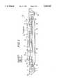
- FIG. 1is a sectional view of one embodiment of a transducer assembly in accordance with the invention taken along lines A--A of FIG. 2;
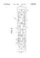
- FIG. 2is a plan view of the transducer assembly
- FIG. 3is a detailed view in section of the transducer
- FIG. 4is a perspective showing in side elevation of the ultrasonic inspection apparatus of the invention employing a transducer assembly in accordance with the embodiment of FIGS. 1, 2 and 3;
- FIG. 5is a perspective showing in front elevation of the apparatus of FIG. 4.
- the transducer assembly 10has an elongated transducer housing 12.
- a plurality of transducers 14, four of which are shown in the embodiment of FIGS. 1 and 2are mounted within an open area 16 of the transducer housing.
- the transducers 14are secured within the open area 16 by bolts 18.
- Each transducer 14has a terminal 20 for connection to a power source (not shown).
- a set of wheels 22is journalled for rotation on each end of the transducer housing.
- An elastic membrane 24 of water-impervious, elastic material, such as polyurethane,is connected in water sealing engagement at edges 26 thereof to the transducer housing.
- the membrane 24has a flat area 27 and tapered end portions 28.
- a reservoir 30is provided by this membrane 24 between the membrane and the transducers mounted in the open area 16 of the transducer housing. Valves 32 are provided at each end of the reservoir to provide for the introduction and removal of water used as the ultrasonic coupling fluid with respect to the reservoir 30.
- the reservoir 30is filled with water through valves 32.
- the transducer assemblyis placed adjacent the tubing to be inspected with the membrane 24 being compressed against the surface of the tubing. This causes distortion of the membrane to conform to the contour of the tubing, as shown by the dashed lines constituting the surface 27 of the membrane shown in FIG. 3.
- the wateris removed through valves 32 until the membrane conforms to the surface of the tubing.
- FIGS. 4 and 5show a tubing 34 to be inspected by the transducer assembly 10, with the surface 27 of the membrane 24 conforming to the contour of the tubing surface. During inspection, as shown in FIG. 4, the tubing is maintained out of contact with the surface 27 of the membrane during rotation thereof.
- water-spray nozzle 36spraying water onto the rotating surface of the tubing to provide water between the surface 27 of the membrane 24 and the surface of the tubing 34.
- the membrane 24is maintained out of contact by this flow of water 38 with the water maintaining the necessary ultrasonic coupling with the transducers of the assembly.
- the two sets of wheels 22serve to guide the transducer assembly over the surface of the tubing to maintain accurate spacing relative to the tubing surface.
Landscapes
- Physics & Mathematics (AREA)
- General Physics & Mathematics (AREA)
- Health & Medical Sciences (AREA)
- Life Sciences & Earth Sciences (AREA)
- Chemical & Material Sciences (AREA)
- Analytical Chemistry (AREA)
- Biochemistry (AREA)
- General Health & Medical Sciences (AREA)
- Immunology (AREA)
- Pathology (AREA)
- Investigating Or Analyzing Materials By The Use Of Ultrasonic Waves (AREA)
- Length Measuring Devices Characterised By Use Of Acoustic Means (AREA)
Abstract
Description
This application is a continuation of application Ser. No. 08/088,039, filed Jul. 6, 1993, now abandoned.
1. Field of the Invention
The invention relates to a method for the ultrasonic inspection of pipe and tubing to determine characteristics thereof, such as wall thickness or defects, and to a transducer assembly for use with this method.
2. Description of the Prior Art
Incident to the manufacture or use of tubular products, it is common practice to inspect the tubing for detection of variations in the wall thickness thereof and to detect the presence of surface and internal defects. For this purpose, it is known to use ultrasonic inspection techniques. With these techniques, it is customary to employ a transducer to impart high-frequency sound energy into the tubing to be tested. The high-frequency sound energy is transmitted through an ultrasonic fluid to the tubing and is reflected back from the tubing to the transducer. Monitoring of this back reflection of the sound energy is used to determine characteristics such as wall thickness and the presence of defects in the form of discontinuities in the tubing.
With inspection techniques of this type, relative rotational movement is imparted between the tubing being inspected and the transducer assembly used for the inspection. To achieve precise and reliable test results, it is necessary to maintain effective ultrasonic coupling between the transducers and the surface of the tubing during this relative rotational movement. This necessitates a transducer assembly having a surface coupled to the transducers that conforms to the contour of the surface of the tubing being inspected. To maintain this contact, it is desirable that the contacting surface of the transducer assembly be of a material that will deform into conformity with the tubing contour. For effective ultrasonic coupling, contact of the conforming material must be maintained while effecting relative rotational movement of the tubing surface and the conforming material of the transducer assembly. This results in rapid wear and destruction of this conforming surface of the transducer assembly and thus necessitates frequency removal and replacement. If the surface is attempted to be maintained in light contact to avoid wear and abrasion thereof, this results in ineffective ultrasonic coupling of the transducers and thus imprecise and unreliable test results.
It is accordingly a primary object of the present invention to provide an ultrasonic testing method for pipe and tubing and a transducer for use therewith wherein effective ultrasonic coupling may be maintained during relative rotational movement of a transducer assembly and tubing during ultrasonic testing, while avoiding wear and abrasion of the conforming surface portion of the transducer assembly.
A more specific object of the invention is to provide a method and assembly of this type wherein effective ultrasonic coupling may be provided between an ultrasonic transducer and tubing surface during relative rotational movement incident to inspection, while maintaining the conforming surface of the transducer assembly out of contact with the tubing surface.
The transducer assembly in accordance with the invention has an elongated housing with a plurality of ultrasonic transducers mounted on an upper surface of the housing and along a major axis thereof. A guide which may constitute a set of two wheels is mounted on each of two opposite ends of the housing. A plurality of ultrasonic transducers are mounted between the guides and on the housing. An elastic membrane of water-impervious, elastic material is provided in water-sealed connection at edge portions thereof to a lower surface of the housing. The edge portions of this membrane terminate on the lower surface of the housing at a location short of each guide. The elastic membrane forms a reservoir of ultrasonic fluid within the membrane, with this fluid being coupled to the plurality of transducers. Valves are provided for the selective and controlled introduction and removal of this ultrasonic fluid to and from the reservoir.
The ultrasonic fluid is preferably water.
The elongated transducer has an elongated, open interior portion on the upper surface thereof and the plurality of ultrasonic transducers are mounted within this open interior portion.
The reservoir provided by the membrane is in communication with this open interior portion of the elongated transducer housing.
The elastic membrane has an elongated flat bottom surface terminating at tapered opposed end portions adjacent each wheel.
In accordance with the method in the invention, the transducer assembly is employed by filling the reservoir with ultrasonic fluid and then compressing the fluid-filled membrane against an exterior surface of the tubing to be inspected. A quantity of the ultrasonic fluid is removed from the reservoir in an amount sufficient to permit the elastic membrane to conform to the contour of the exterior transverse surface of the tubing. Then inspection of the tubing is performed by introducing flowing ultrasonic liquid, preferably water, between the elastic membrane and adjacent surfaces of the tubing, while producing relative rotational movement between the transducer assembly and the tubing. During this operation, the elastic membrane and the plurality of ultrasonic transducer are ultrasonically coupled to the tubing by the flowing ultrasonic liquid and the ultrasonic fluid within the reservoir, while maintaining the elastic membrane out-of-contact with the tubing.
Preferably the water is introduced by spraying the water onto the tubing during the relative rotational movement between the transducer assembly and the tubing. This relative rotational movement is preferably produced by rotating the transducer assembly while moving the tubing linearly. It is also possible to maintain the transducer assembly stationary while simultaneously rotating and moving the tubing linearly.
FIG. 1 is a sectional view of one embodiment of a transducer assembly in accordance with the invention taken along lines A--A of FIG. 2;
FIG. 2 is a plan view of the transducer assembly;
FIG. 3 is a detailed view in section of the transducer;
FIG. 4 is a perspective showing in side elevation of the ultrasonic inspection apparatus of the invention employing a transducer assembly in accordance with the embodiment of FIGS. 1, 2 and 3; and
FIG. 5 is a perspective showing in front elevation of the apparatus of FIG. 4.
With reference to the drawings and for the present to FIGS. 1 and 2 thereof, there is shown a transducer assembly designated generally as 10 in accordance with one embodiment of the invention. Thetransducer assembly 10 has anelongated transducer housing 12. A plurality oftransducers 14, four of which are shown in the embodiment of FIGS. 1 and 2, are mounted within anopen area 16 of the transducer housing. Thetransducers 14 are secured within theopen area 16 bybolts 18. Eachtransducer 14 has aterminal 20 for connection to a power source (not shown). A set ofwheels 22 is journalled for rotation on each end of the transducer housing. Anelastic membrane 24 of water-impervious, elastic material, such as polyurethane, is connected in water sealing engagement atedges 26 thereof to the transducer housing. Themembrane 24 has aflat area 27 and taperedend portions 28. Areservoir 30 is provided by thismembrane 24 between the membrane and the transducers mounted in theopen area 16 of the transducer housing.Valves 32 are provided at each end of the reservoir to provide for the introduction and removal of water used as the ultrasonic coupling fluid with respect to thereservoir 30.
In accordance with the method of the invention, thereservoir 30 is filled with water throughvalves 32. Then the transducer assembly is placed adjacent the tubing to be inspected with themembrane 24 being compressed against the surface of the tubing. This causes distortion of the membrane to conform to the contour of the tubing, as shown by the dashed lines constituting thesurface 27 of the membrane shown in FIG. 3. Then the water is removed throughvalves 32 until the membrane conforms to the surface of the tubing. FIGS. 4 and 5 show atubing 34 to be inspected by thetransducer assembly 10, with thesurface 27 of themembrane 24 conforming to the contour of the tubing surface. During inspection, as shown in FIG. 4, the tubing is maintained out of contact with thesurface 27 of the membrane during rotation thereof. This is achieved by water-spray nozzle 36 spraying water onto the rotating surface of the tubing to provide water between thesurface 27 of themembrane 24 and the surface of thetubing 34. Themembrane 24 is maintained out of contact by this flow ofwater 38 with the water maintaining the necessary ultrasonic coupling with the transducers of the assembly.
In this manner, effective ultrasonic coupling with the transducers is provided to achieve precise and reliable inspection, while protecting thesurface 27 of themembrane 24 from contact and thus wear and abrasion caused by the tubing surface during inspection. The two sets ofwheels 22 serve to guide the transducer assembly over the surface of the tubing to maintain accurate spacing relative to the tubing surface.
Claims (4)
1. A method for the ultrasonic inspection of tubing comprising, providing a transducer assembly including an elongated transducer housing having a plurality of ultrasonic transducers mounted on an upper surface and along a major axis of said housing, providing guides mounted on each of two opposed ends of said housing, with said plurality of ultrasonic transducers being mounted therebetween, providing an elongated elastic membrane of water-impervious, elastic material in water-tight sealed connection at edge portions thereof to a lower surface of said housing, with said edge portions of said membrane terminating on said lower surface of said housing at a location short of each said guides and with opposed width portions of said membrane extending beyond said housing, with said elastic membrane forming a reservoir of ultrasonic fluid within said membrane with said fluid being coupled To said plurality of transducers, providing means for selective and controlled introduction and removal of said ultrasonic fluid with respect to said reservoir, compressing said elastic membrane against an exterior surface of said tubing to be inspected, removing a quantity of said ultrasonic fluid from said reservoir sufficient to cause said elastic membrane to distort and conform to an arcuate contour of an exterior transverse surface of said tubing, introducing flowing additional ultrasonic liquid between said elastic membrane and an adjacent surface of said tubing, while producing relative rotational movement between said transducer assembly and said tubing to maintain said elastic membrane distorted and conforming to said arcuate contour of said exterior surface of said tubing and said plurality of ultrasonic transducers ultrasonically coupled to said tubing by said flowing ultrasonic liquid and said ultrasonic fluid within said reservoir, with said flowing ultrasonic liquid maintaining said elastic membrane out-of-contact with said tubing.
2. The method of claim 1, wherein said flowing ultrasonic liquid is water.
3. The method of claim 2, wherein said water is introduced by spraying said water onto said tubing during said relative rotational movement between said transducer assembly and said tubing.
4. The method of claim 2, wherein said relative rotational movement is produced by rotating said transducer assembly.
Priority Applications (1)
| Application Number | Priority Date | Filing Date | Title |
|---|---|---|---|
| US08/389,569US5585565A (en) | 1993-07-06 | 1995-02-16 | Method for the ultrasonic inspection of pipe and tubing and a transducer assembly for use therewith |
Applications Claiming Priority (2)
| Application Number | Priority Date | Filing Date | Title |
|---|---|---|---|
| US8803993A | 1993-07-06 | 1993-07-06 | |
| US08/389,569US5585565A (en) | 1993-07-06 | 1995-02-16 | Method for the ultrasonic inspection of pipe and tubing and a transducer assembly for use therewith |
Related Parent Applications (1)
| Application Number | Title | Priority Date | Filing Date |
|---|---|---|---|
| US8803993AContinuation | 1993-07-06 | 1993-07-06 |
Publications (1)
| Publication Number | Publication Date |
|---|---|
| US5585565Atrue US5585565A (en) | 1996-12-17 |
Family
ID=22208989
Family Applications (1)
| Application Number | Title | Priority Date | Filing Date |
|---|---|---|---|
| US08/389,569Expired - LifetimeUS5585565A (en) | 1993-07-06 | 1995-02-16 | Method for the ultrasonic inspection of pipe and tubing and a transducer assembly for use therewith |
Country Status (9)
| Country | Link |
|---|---|
| US (1) | US5585565A (en) |
| EP (1) | EP0633451B1 (en) |
| JP (1) | JP3582604B2 (en) |
| BR (1) | BR9402610A (en) |
| CA (1) | CA2127221C (en) |
| DE (1) | DE69429692T2 (en) |
| ES (1) | ES2171435T3 (en) |
| NO (1) | NO319092B1 (en) |
| SG (1) | SG52640A1 (en) |
Cited By (51)
| Publication number | Priority date | Publication date | Assignee | Title |
|---|---|---|---|---|
| US5936163A (en)* | 1998-05-13 | 1999-08-10 | Greathouse; John D. | Portable high temperature ultrasonic testing (UT) piezo probe with cooling apparatus |
| US5963030A (en)* | 1998-03-30 | 1999-10-05 | Union Oil Company Of California | Pipe inspection apparatus and process |
| EP0971064A2 (en) | 1998-07-10 | 2000-01-12 | Milliken & Company | Floor mat solely comprised of monofilament nylon fiber and having an ozone resistant non-staining backing sheet |
| WO2001096808A3 (en)* | 2000-06-12 | 2002-05-02 | Hydro Quebec | Bracelet for moving ultrasonic sensors along a pipe |
| US20020114917A1 (en)* | 1999-06-17 | 2002-08-22 | Seiin Kobayashi | Methods of coloring solution-dyed nylon |
| US6578424B1 (en)* | 2000-09-27 | 2003-06-17 | Digital Wave Corporation | Hand-held variable angle membrane (VAM) ultrasonic scanning head for the noninvasive detection of corrosion, MIC and foreign objects in pipes |
| US6591680B2 (en)* | 2001-06-15 | 2003-07-15 | General Electric Company | System and method for ultrasonic immersion inspection of components |
| WO2003016897A3 (en)* | 2001-08-14 | 2003-11-20 | Varco Int | A method and apparatus for inspecting a product with ultrasound |
| US20030233880A1 (en)* | 2002-06-25 | 2003-12-25 | Siverling David E. | Ultrasonic tubular inspection apparatus having fluid interface and system and method incorporating same |
| US6684706B2 (en) | 2000-11-29 | 2004-02-03 | Cooper Cameron Corporation | Ultrasonic testing system |
| US20040020298A1 (en)* | 2002-08-02 | 2004-02-05 | Siverling David E. | Apparatus for end-to-end ultrasonic inspection of tubular goods and system and method incorporating same |
| US20040050167A1 (en)* | 2002-09-13 | 2004-03-18 | Linares Lionel S. | Pipe inspection systems and methods |
| US20050193839A1 (en)* | 2004-03-05 | 2005-09-08 | Daniel Gronvall | Self adjusting sensor mounting device |
| US20060048589A1 (en)* | 2003-01-08 | 2006-03-09 | Eric Lavoie | Apparatus for moving a measuring device along a pipe |
| US20060241533A1 (en)* | 2003-04-22 | 2006-10-26 | Benjamin Geller | Apparatus and method for treatment of damaged tissue |
| US20060267594A1 (en)* | 2005-05-27 | 2006-11-30 | Siemens Westinghouse Power Corporation | Power generation unit condition monitor using frequency profile analysis |
| FR2891910A1 (en)* | 2005-10-10 | 2007-04-13 | Eads Ccr Groupement D Interet | Ultrasonic piece e.g. concrete plate, inspecting device for e.g. naval field, has guiding element with body to form thin film of couplant on surface of piece, and membrane mounted on body and maintaining constant thickness of film |
| US20070227249A1 (en)* | 2006-03-04 | 2007-10-04 | Intelligendt Systems & Services Gmbh & Co. Kg | Method for the ultrasound testing of a workpiece within a curved region of its surface and device suitable for the execution of the process |
| US20070239018A1 (en)* | 2006-02-02 | 2007-10-11 | The Boeing Company | Thin-film ultrasonic probe |
| US20080061000A1 (en)* | 2006-09-08 | 2008-03-13 | Kimberly Clark Worldwide, Inc. | Ultrasonic Treatment System For Separating Compounds From Aqueous Effluent |
| US20080062811A1 (en)* | 2006-09-08 | 2008-03-13 | Kimberly-Clark Worldwide, Inc. | Ultrasonic liquid treatment chamber and continuous flow mixing system |
| WO2008043888A1 (en)* | 2006-10-11 | 2008-04-17 | Eads Ccr | Device for the ultrasound control of a part |
| US20080159063A1 (en)* | 2006-12-28 | 2008-07-03 | Kimberly-Clark Worldwide, Inc. | Ultrasonic liquid treatment system |
| US20080202245A1 (en)* | 2007-02-28 | 2008-08-28 | Young Fred D | Probe for inspection of edges of a structure |
| US20080276710A1 (en)* | 2007-05-07 | 2008-11-13 | Reflect Scientific Dba Miralogix | Immersed probe over pressurized elastomer |
| US20090014377A1 (en)* | 2007-07-12 | 2009-01-15 | Kimberly-Clark Worldwide, Inc. | Ultrasonic treatment chamber having electrode properties |
| US20090014393A1 (en)* | 2007-07-12 | 2009-01-15 | Kimberly-Clark Worldwide, Inc. | Treatment chamber for separating compounds from aqueous effluent |
| US20090017225A1 (en)* | 2007-07-12 | 2009-01-15 | Kimberly-Clark Worldwide, Inc. | Delivery systems for delivering functional compounds to substrates and processes of using the same |
| US20090088644A1 (en)* | 2007-09-29 | 2009-04-02 | Shenzhen Mindray Bio-Medical Electronics Co., Ltd. | Circular arc wide beam transmission method and apparatus for ultrasonic imaging |
| US20090166177A1 (en)* | 2007-12-28 | 2009-07-02 | Kimberly-Clark Worldwide, Inc. | Ultrasonic treatment chamber for preparing emulsions |
| US20090168590A1 (en)* | 2007-12-28 | 2009-07-02 | Kimberly-Clark Worldwide, Inc. | Ultrasonic treatment chamber for preparing antimicrobial formulations |
| US20090165223A1 (en)* | 2007-12-27 | 2009-07-02 | Kimberly-Clark Worldwide, Inc. | Process for applying one or more treatment agents to a textile web |
| US7637162B2 (en) | 2007-10-01 | 2009-12-29 | Spirit Aerosystems, Inc. | Mechanism for adaptive contour compliance |
| US7673516B2 (en) | 2006-12-28 | 2010-03-09 | Kimberly-Clark Worldwide, Inc. | Ultrasonic liquid treatment system |
| US20100152042A1 (en)* | 2008-12-15 | 2010-06-17 | Kimberly-Clark Worldwide, Inc. | Compositions comprising metal-modified silica nanoparticles |
| US20100150859A1 (en)* | 2008-12-15 | 2010-06-17 | Kimberly-Clark Worldwide, Inc. | Methods of preparing metal-modified silica nanoparticles |
| US7757561B2 (en)* | 2005-08-01 | 2010-07-20 | Covaris, Inc. | Methods and systems for processing samples using acoustic energy |
| US20100206742A1 (en)* | 2007-12-05 | 2010-08-19 | Kimberly-Clark Worldwide, Inc. | Ultrasonic treatment chamber for treating hydrogen isotopes |
| US20110072904A1 (en)* | 2009-09-29 | 2011-03-31 | National Oilwell Varco, L.P. | Ultrasonic Probe Apparatus, System, and Method for Detecting Flaws in a Tubular |
| US20110072905A1 (en)* | 2009-09-29 | 2011-03-31 | National Oilwell Varco, L.P. | Membrane-Coupled Ultrasonic Probe System for Detecting Flaws in a Tubular |
| US8057573B2 (en) | 2007-12-28 | 2011-11-15 | Kimberly-Clark Worldwide, Inc. | Ultrasonic treatment chamber for increasing the shelf life of formulations |
| US8206024B2 (en) | 2007-12-28 | 2012-06-26 | Kimberly-Clark Worldwide, Inc. | Ultrasonic treatment chamber for particle dispersion into formulations |
| US8454889B2 (en) | 2007-12-21 | 2013-06-04 | Kimberly-Clark Worldwide, Inc. | Gas treatment system |
| US8702836B2 (en) | 2006-11-22 | 2014-04-22 | Covaris, Inc. | Methods and apparatus for treating samples with acoustic energy to form particles and particulates |
| US8858892B2 (en) | 2007-12-21 | 2014-10-14 | Kimberly-Clark Worldwide, Inc. | Liquid treatment system |
| US20150096382A1 (en)* | 2013-10-07 | 2015-04-09 | Sikorsky Aircraft Corporation | Ultrasonic scanning fixture assembly |
| US9239036B2 (en) | 2006-09-08 | 2016-01-19 | Kimberly-Clark Worldwide, Inc. | Ultrasonic liquid treatment and delivery system and process |
| US9283188B2 (en) | 2006-09-08 | 2016-03-15 | Kimberly-Clark Worldwide, Inc. | Delivery systems for delivering functional compounds to substrates and processes of using the same |
| US9421504B2 (en) | 2007-12-28 | 2016-08-23 | Kimberly-Clark Worldwide, Inc. | Ultrasonic treatment chamber for preparing emulsions |
| US10794871B1 (en) | 2018-05-23 | 2020-10-06 | The United States Of America As Represented By The Secretary Of The Air Force | Elastomer ultrasonic coupling adaptor for focused transducers |
| CN113588799A (en)* | 2021-06-22 | 2021-11-02 | 南昌航空大学 | Flexible ultrasonic focusing detection probe for ultrasonic nondestructive detection of laser welding seam of lithium battery ring electrode |
Families Citing this family (5)
| Publication number | Priority date | Publication date | Assignee | Title |
|---|---|---|---|---|
| KR100464925B1 (en)* | 1997-12-11 | 2005-05-17 | 국방과학연구소 | Fixed structure of hydrophone for sound wave detector |
| AU2003902766A0 (en)* | 2003-06-02 | 2003-06-19 | Onesteel Manufacturing Pty Ltd | Ultrasonic testing of pipe |
| CA2554906C (en) | 2006-05-10 | 2008-09-02 | Robert Allan Simmons | Method and apparatus for conveying an ultrasonic sensor about an outer peripheral surface of a tube |
| CN106353046B (en)* | 2016-08-30 | 2019-12-24 | 吴江梅塞尔工业气体有限公司 | DISS valve leak detection joint and rapid leak detection method |
| CN113125565B (en)* | 2021-04-20 | 2023-09-15 | 内蒙古科技大学 | Ultrasonic detection water bag and detection device |
Citations (10)
| Publication number | Priority date | Publication date | Assignee | Title |
|---|---|---|---|---|
| US3616684A (en)* | 1969-11-20 | 1971-11-02 | Bethlehem Steel Corp | Ultrasonic inspection carriage |
| US3631714A (en)* | 1969-11-20 | 1972-01-04 | Bethlehem Steel Corp | Ultrasonic inspection probe |
| US3771354A (en)* | 1971-12-06 | 1973-11-13 | Rockwell International Corp | Rapid ultrasonic inspection apparatus |
| US3777552A (en)* | 1971-11-09 | 1973-12-11 | Wages C | Ultrasonic scanning system for in-place inspection of brazed tube joints |
| US3777554A (en)* | 1969-05-27 | 1973-12-11 | United States Steel Corp | Ultrasonic testing apparatus |
| US3798961A (en)* | 1971-02-25 | 1974-03-26 | C Flambard | Apparatus for non-destructive checking of workpieces |
| US3958451A (en)* | 1973-12-12 | 1976-05-25 | Inspection Technology Development, Inc. | Ultrasonic inspection apparatus |
| US4143554A (en)* | 1977-03-14 | 1979-03-13 | Second Foundation | Ultrasonic scanner |
| US5007291A (en)* | 1989-10-05 | 1991-04-16 | Scan Systems, Inc. | Ultrasonic inspection apparatus with centering means for tubular members |
| US5079952A (en)* | 1989-03-25 | 1992-01-14 | Poppan Printing Co. | Ultrasonic transducer assembly and ultrasonic acoustic microscope |
Family Cites Families (4)
| Publication number | Priority date | Publication date | Assignee | Title |
|---|---|---|---|---|
| US2992553A (en)* | 1957-04-24 | 1961-07-18 | Ivan L Joy | Coupling method and apparatus for ultrasonic testing of solid bodies |
| US3205702A (en)* | 1963-12-30 | 1965-09-14 | Chemetron Corp | Ultrasonic coupling device |
| JPS59116539A (en)* | 1982-12-24 | 1984-07-05 | Hitachi Ltd | Pipe inspection device |
| DE8418008U1 (en)* | 1984-06-14 | 1985-10-10 | Jurid Werke Gmbh, 2056 Glinde | Test head for the non-destructive testing of materials, material connections and the like. Using ultrasound |
- 1994
- 1994-06-02DEDE69429692Tpatent/DE69429692T2/ennot_activeExpired - Fee Related
- 1994-06-02SGSG1996007258Apatent/SG52640A1/enunknown
- 1994-06-02EPEP94303979Apatent/EP0633451B1/ennot_activeExpired - Lifetime
- 1994-06-02ESES94303979Tpatent/ES2171435T3/ennot_activeExpired - Lifetime
- 1994-06-27JPJP16580394Apatent/JP3582604B2/ennot_activeExpired - Lifetime
- 1994-06-30BRBR9402610Apatent/BR9402610A/ennot_activeIP Right Cessation
- 1994-06-30CACA002127221Apatent/CA2127221C/ennot_activeExpired - Lifetime
- 1994-06-30NONO19942484Apatent/NO319092B1/ennot_activeIP Right Cessation
- 1995
- 1995-02-16USUS08/389,569patent/US5585565A/ennot_activeExpired - Lifetime
Patent Citations (10)
| Publication number | Priority date | Publication date | Assignee | Title |
|---|---|---|---|---|
| US3777554A (en)* | 1969-05-27 | 1973-12-11 | United States Steel Corp | Ultrasonic testing apparatus |
| US3616684A (en)* | 1969-11-20 | 1971-11-02 | Bethlehem Steel Corp | Ultrasonic inspection carriage |
| US3631714A (en)* | 1969-11-20 | 1972-01-04 | Bethlehem Steel Corp | Ultrasonic inspection probe |
| US3798961A (en)* | 1971-02-25 | 1974-03-26 | C Flambard | Apparatus for non-destructive checking of workpieces |
| US3777552A (en)* | 1971-11-09 | 1973-12-11 | Wages C | Ultrasonic scanning system for in-place inspection of brazed tube joints |
| US3771354A (en)* | 1971-12-06 | 1973-11-13 | Rockwell International Corp | Rapid ultrasonic inspection apparatus |
| US3958451A (en)* | 1973-12-12 | 1976-05-25 | Inspection Technology Development, Inc. | Ultrasonic inspection apparatus |
| US4143554A (en)* | 1977-03-14 | 1979-03-13 | Second Foundation | Ultrasonic scanner |
| US5079952A (en)* | 1989-03-25 | 1992-01-14 | Poppan Printing Co. | Ultrasonic transducer assembly and ultrasonic acoustic microscope |
| US5007291A (en)* | 1989-10-05 | 1991-04-16 | Scan Systems, Inc. | Ultrasonic inspection apparatus with centering means for tubular members |
Cited By (81)
| Publication number | Priority date | Publication date | Assignee | Title |
|---|---|---|---|---|
| US5963030A (en)* | 1998-03-30 | 1999-10-05 | Union Oil Company Of California | Pipe inspection apparatus and process |
| US5936163A (en)* | 1998-05-13 | 1999-08-10 | Greathouse; John D. | Portable high temperature ultrasonic testing (UT) piezo probe with cooling apparatus |
| EP0971064A2 (en) | 1998-07-10 | 2000-01-12 | Milliken & Company | Floor mat solely comprised of monofilament nylon fiber and having an ozone resistant non-staining backing sheet |
| US20020114917A1 (en)* | 1999-06-17 | 2002-08-22 | Seiin Kobayashi | Methods of coloring solution-dyed nylon |
| WO2001096808A3 (en)* | 2000-06-12 | 2002-05-02 | Hydro Quebec | Bracelet for moving ultrasonic sensors along a pipe |
| US6497159B1 (en) | 2000-06-12 | 2002-12-24 | Hydro-Quebec | Bracelet for moving ultrasonic sensors along a pipe |
| US6578424B1 (en)* | 2000-09-27 | 2003-06-17 | Digital Wave Corporation | Hand-held variable angle membrane (VAM) ultrasonic scanning head for the noninvasive detection of corrosion, MIC and foreign objects in pipes |
| US6684706B2 (en) | 2000-11-29 | 2004-02-03 | Cooper Cameron Corporation | Ultrasonic testing system |
| US6591680B2 (en)* | 2001-06-15 | 2003-07-15 | General Electric Company | System and method for ultrasonic immersion inspection of components |
| WO2003016897A3 (en)* | 2001-08-14 | 2003-11-20 | Varco Int | A method and apparatus for inspecting a product with ultrasound |
| US20030233880A1 (en)* | 2002-06-25 | 2003-12-25 | Siverling David E. | Ultrasonic tubular inspection apparatus having fluid interface and system and method incorporating same |
| US20040020298A1 (en)* | 2002-08-02 | 2004-02-05 | Siverling David E. | Apparatus for end-to-end ultrasonic inspection of tubular goods and system and method incorporating same |
| US6945113B2 (en)* | 2002-08-02 | 2005-09-20 | Siverling David E | End-to-end ultrasonic inspection of tubular goods |
| GB2406909B (en)* | 2002-09-13 | 2005-12-28 | Ctes L P | An apparatus and method for inspecting a tubular with ultrasound |
| GB2406909A (en)* | 2002-09-13 | 2005-04-13 | Ctes L P | An apparatus and method for inspecting a tubular with ultrasound by using a deformable acoustic coupling element |
| US20040050167A1 (en)* | 2002-09-13 | 2004-03-18 | Linares Lionel S. | Pipe inspection systems and methods |
| WO2004025291A3 (en)* | 2002-09-13 | 2004-07-01 | Ctes L P | An apparatus and method for inspecting a tubular with ultrasound by using a deformable acoustic coupling element |
| US6782751B2 (en)* | 2002-09-13 | 2004-08-31 | Ctes, L.C. | Pipe inspection systems and methods |
| US7284456B2 (en) | 2003-01-08 | 2007-10-23 | Hydro-Quebec Of Montreal | Apparatus for moving a measuring device along a pipe |
| US20060048589A1 (en)* | 2003-01-08 | 2006-03-09 | Eric Lavoie | Apparatus for moving a measuring device along a pipe |
| US20060241533A1 (en)* | 2003-04-22 | 2006-10-26 | Benjamin Geller | Apparatus and method for treatment of damaged tissue |
| US7100462B2 (en)* | 2004-03-05 | 2006-09-05 | Buglab Llc | Self adjusting sensor mounting device |
| US20050193839A1 (en)* | 2004-03-05 | 2005-09-08 | Daniel Gronvall | Self adjusting sensor mounting device |
| US7372279B2 (en) | 2005-05-27 | 2008-05-13 | Siemens Power Generation, Inc. | Power generation unit condition monitor using frequency profile analysis |
| US20060267594A1 (en)* | 2005-05-27 | 2006-11-30 | Siemens Westinghouse Power Corporation | Power generation unit condition monitor using frequency profile analysis |
| US7757561B2 (en)* | 2005-08-01 | 2010-07-20 | Covaris, Inc. | Methods and systems for processing samples using acoustic energy |
| FR2891910A1 (en)* | 2005-10-10 | 2007-04-13 | Eads Ccr Groupement D Interet | Ultrasonic piece e.g. concrete plate, inspecting device for e.g. naval field, has guiding element with body to form thin film of couplant on surface of piece, and membrane mounted on body and maintaining constant thickness of film |
| US20070239018A1 (en)* | 2006-02-02 | 2007-10-11 | The Boeing Company | Thin-film ultrasonic probe |
| US7637163B2 (en)* | 2006-02-02 | 2009-12-29 | The Boeing Company | Thin-film ultrasonic probe |
| US7516664B2 (en)* | 2006-03-04 | 2009-04-14 | Intelligendt Systems & Services Gmbh & Co. Kg | Method for the ultrasound testing of a workpiece within a curved region of its surface and device suitable for the execution of the process |
| US20070227249A1 (en)* | 2006-03-04 | 2007-10-04 | Intelligendt Systems & Services Gmbh & Co. Kg | Method for the ultrasound testing of a workpiece within a curved region of its surface and device suitable for the execution of the process |
| US8616759B2 (en) | 2006-09-08 | 2013-12-31 | Kimberly-Clark Worldwide, Inc. | Ultrasonic treatment system |
| US8034286B2 (en) | 2006-09-08 | 2011-10-11 | Kimberly-Clark Worldwide, Inc. | Ultrasonic treatment system for separating compounds from aqueous effluent |
| US20080062811A1 (en)* | 2006-09-08 | 2008-03-13 | Kimberly-Clark Worldwide, Inc. | Ultrasonic liquid treatment chamber and continuous flow mixing system |
| US9239036B2 (en) | 2006-09-08 | 2016-01-19 | Kimberly-Clark Worldwide, Inc. | Ultrasonic liquid treatment and delivery system and process |
| US7703698B2 (en) | 2006-09-08 | 2010-04-27 | Kimberly-Clark Worldwide, Inc. | Ultrasonic liquid treatment chamber and continuous flow mixing system |
| US20080061000A1 (en)* | 2006-09-08 | 2008-03-13 | Kimberly Clark Worldwide, Inc. | Ultrasonic Treatment System For Separating Compounds From Aqueous Effluent |
| US9283188B2 (en) | 2006-09-08 | 2016-03-15 | Kimberly-Clark Worldwide, Inc. | Delivery systems for delivering functional compounds to substrates and processes of using the same |
| WO2008043888A1 (en)* | 2006-10-11 | 2008-04-17 | Eads Ccr | Device for the ultrasound control of a part |
| US8702836B2 (en) | 2006-11-22 | 2014-04-22 | Covaris, Inc. | Methods and apparatus for treating samples with acoustic energy to form particles and particulates |
| US7712353B2 (en)* | 2006-12-28 | 2010-05-11 | Kimberly-Clark Worldwide, Inc. | Ultrasonic liquid treatment system |
| US20080159063A1 (en)* | 2006-12-28 | 2008-07-03 | Kimberly-Clark Worldwide, Inc. | Ultrasonic liquid treatment system |
| US7673516B2 (en) | 2006-12-28 | 2010-03-09 | Kimberly-Clark Worldwide, Inc. | Ultrasonic liquid treatment system |
| US7571649B2 (en)* | 2007-02-28 | 2009-08-11 | The Boeing Company | Probe for inspection of edges of a structure |
| US20080202245A1 (en)* | 2007-02-28 | 2008-08-28 | Young Fred D | Probe for inspection of edges of a structure |
| US8225669B2 (en)* | 2007-05-07 | 2012-07-24 | New Gate Technologies | Immersed probe over pressurized elastomer |
| US20080276710A1 (en)* | 2007-05-07 | 2008-11-13 | Reflect Scientific Dba Miralogix | Immersed probe over pressurized elastomer |
| US20090014393A1 (en)* | 2007-07-12 | 2009-01-15 | Kimberly-Clark Worldwide, Inc. | Treatment chamber for separating compounds from aqueous effluent |
| US20090014377A1 (en)* | 2007-07-12 | 2009-01-15 | Kimberly-Clark Worldwide, Inc. | Ultrasonic treatment chamber having electrode properties |
| US7785674B2 (en) | 2007-07-12 | 2010-08-31 | Kimberly-Clark Worldwide, Inc. | Delivery systems for delivering functional compounds to substrates and processes of using the same |
| US20090017225A1 (en)* | 2007-07-12 | 2009-01-15 | Kimberly-Clark Worldwide, Inc. | Delivery systems for delivering functional compounds to substrates and processes of using the same |
| US7947184B2 (en) | 2007-07-12 | 2011-05-24 | Kimberly-Clark Worldwide, Inc. | Treatment chamber for separating compounds from aqueous effluent |
| US7998322B2 (en) | 2007-07-12 | 2011-08-16 | Kimberly-Clark Worldwide, Inc. | Ultrasonic treatment chamber having electrode properties |
| US20090088644A1 (en)* | 2007-09-29 | 2009-04-02 | Shenzhen Mindray Bio-Medical Electronics Co., Ltd. | Circular arc wide beam transmission method and apparatus for ultrasonic imaging |
| US8001843B2 (en)* | 2007-09-29 | 2011-08-23 | Shenzhen Mindray Bio-Medical Electronics Co., Ltd. | Circular arc wide beam transmission method and apparatus for ultrasonic imaging |
| US7637162B2 (en) | 2007-10-01 | 2009-12-29 | Spirit Aerosystems, Inc. | Mechanism for adaptive contour compliance |
| US20100206742A1 (en)* | 2007-12-05 | 2010-08-19 | Kimberly-Clark Worldwide, Inc. | Ultrasonic treatment chamber for treating hydrogen isotopes |
| US8858892B2 (en) | 2007-12-21 | 2014-10-14 | Kimberly-Clark Worldwide, Inc. | Liquid treatment system |
| US8454889B2 (en) | 2007-12-21 | 2013-06-04 | Kimberly-Clark Worldwide, Inc. | Gas treatment system |
| US8632613B2 (en) | 2007-12-27 | 2014-01-21 | Kimberly-Clark Worldwide, Inc. | Process for applying one or more treatment agents to a textile web |
| US20090165223A1 (en)* | 2007-12-27 | 2009-07-02 | Kimberly-Clark Worldwide, Inc. | Process for applying one or more treatment agents to a textile web |
| US20090166177A1 (en)* | 2007-12-28 | 2009-07-02 | Kimberly-Clark Worldwide, Inc. | Ultrasonic treatment chamber for preparing emulsions |
| US8057573B2 (en) | 2007-12-28 | 2011-11-15 | Kimberly-Clark Worldwide, Inc. | Ultrasonic treatment chamber for increasing the shelf life of formulations |
| US9421504B2 (en) | 2007-12-28 | 2016-08-23 | Kimberly-Clark Worldwide, Inc. | Ultrasonic treatment chamber for preparing emulsions |
| US8206024B2 (en) | 2007-12-28 | 2012-06-26 | Kimberly-Clark Worldwide, Inc. | Ultrasonic treatment chamber for particle dispersion into formulations |
| US8215822B2 (en) | 2007-12-28 | 2012-07-10 | Kimberly-Clark Worldwide, Inc. | Ultrasonic treatment chamber for preparing antimicrobial formulations |
| US20090168590A1 (en)* | 2007-12-28 | 2009-07-02 | Kimberly-Clark Worldwide, Inc. | Ultrasonic treatment chamber for preparing antimicrobial formulations |
| US8143318B2 (en) | 2007-12-28 | 2012-03-27 | Kimberly-Clark Worldwide, Inc. | Ultrasonic treatment chamber for preparing emulsions |
| US8685178B2 (en) | 2008-12-15 | 2014-04-01 | Kimberly-Clark Worldwide, Inc. | Methods of preparing metal-modified silica nanoparticles |
| US20100150859A1 (en)* | 2008-12-15 | 2010-06-17 | Kimberly-Clark Worldwide, Inc. | Methods of preparing metal-modified silica nanoparticles |
| US20100152042A1 (en)* | 2008-12-15 | 2010-06-17 | Kimberly-Clark Worldwide, Inc. | Compositions comprising metal-modified silica nanoparticles |
| US8163388B2 (en) | 2008-12-15 | 2012-04-24 | Kimberly-Clark Worldwide, Inc. | Compositions comprising metal-modified silica nanoparticles |
| US20110072905A1 (en)* | 2009-09-29 | 2011-03-31 | National Oilwell Varco, L.P. | Membrane-Coupled Ultrasonic Probe System for Detecting Flaws in a Tubular |
| US8166823B2 (en) | 2009-09-29 | 2012-05-01 | National Oilwell Varco, L.P. | Membrane-coupled ultrasonic probe system for detecting flaws in a tubular |
| US20110072904A1 (en)* | 2009-09-29 | 2011-03-31 | National Oilwell Varco, L.P. | Ultrasonic Probe Apparatus, System, and Method for Detecting Flaws in a Tubular |
| US8196472B2 (en) | 2009-09-29 | 2012-06-12 | National Oilwell Varco, L.P. | Ultrasonic probe apparatus, system, and method for detecting flaws in a tubular |
| US20150096382A1 (en)* | 2013-10-07 | 2015-04-09 | Sikorsky Aircraft Corporation | Ultrasonic scanning fixture assembly |
| US9335303B2 (en)* | 2013-10-07 | 2016-05-10 | Sikorsky Aircraft Corporation | Ultrasonic scanning fixture assembly |
| US10794871B1 (en) | 2018-05-23 | 2020-10-06 | The United States Of America As Represented By The Secretary Of The Air Force | Elastomer ultrasonic coupling adaptor for focused transducers |
| CN113588799A (en)* | 2021-06-22 | 2021-11-02 | 南昌航空大学 | Flexible ultrasonic focusing detection probe for ultrasonic nondestructive detection of laser welding seam of lithium battery ring electrode |
| CN113588799B (en)* | 2021-06-22 | 2024-03-15 | 南昌航空大学 | Flexible ultrasonic focused inspection probe for ultrasonic non-destructive testing of laser welds of lithium battery ring electrodes |
Also Published As
| Publication number | Publication date |
|---|---|
| NO319092B1 (en) | 2005-06-20 |
| NO942484D0 (en) | 1994-06-30 |
| JP3582604B2 (en) | 2004-10-27 |
| JPH0772124A (en) | 1995-03-17 |
| DE69429692D1 (en) | 2002-03-14 |
| SG52640A1 (en) | 1998-09-28 |
| DE69429692T2 (en) | 2002-08-29 |
| ES2171435T3 (en) | 2002-09-16 |
| BR9402610A (en) | 1995-04-04 |
| NO942484L (en) | 1995-01-09 |
| CA2127221A1 (en) | 1995-01-07 |
| EP0633451A2 (en) | 1995-01-11 |
| CA2127221C (en) | 2003-10-28 |
| EP0633451A3 (en) | 1995-12-27 |
| EP0633451B1 (en) | 2002-01-23 |
Similar Documents
| Publication | Publication Date | Title |
|---|---|---|
| US5585565A (en) | Method for the ultrasonic inspection of pipe and tubing and a transducer assembly for use therewith | |
| US4593569A (en) | Ultrasonic transducer unit to locate cracks in rail base | |
| US3958451A (en) | Ultrasonic inspection apparatus | |
| KR101878273B1 (en) | Ultrasonic probe | |
| US6945113B2 (en) | End-to-end ultrasonic inspection of tubular goods | |
| US5426980A (en) | Booted ultrasonic transducer | |
| US4472975A (en) | Ultrasonic transducer coupler for flaw detection systems | |
| KR102011778B1 (en) | Probe attachment device for pahsed array ultrasonic test | |
| WO1987003688A1 (en) | Method and apparatus for characterizing defects in tubular members | |
| US4453410A (en) | Method and apparatus for locating material defects in hollow bodies | |
| US5419195A (en) | Ultrasonic booted head probe for motor bore inspection | |
| WO1992007258A1 (en) | Hand-held ultrasonic probe | |
| EP0131065A2 (en) | Method and apparatus for ultrasonic testing of tubular goods | |
| JPS63285438A (en) | Test of air leak in liquid | |
| JPH0545974Y2 (en) | ||
| MXPA94004606A (en) | A method for the ultrasonic inspection of pipe and tubing and a transducer assembly for use therewith | |
| RU1789917C (en) | Method of ultrasonic testing of articles | |
| JPS6415651A (en) | Ultrasonic probe | |
| CN210570629U (en) | Probe and double-probe pipeline profile inclination detection device using same | |
| CN110360987B (en) | Detection apparatus for two probe pipeline section inclinations | |
| EP0359570A3 (en) | Leak detecting apparatus | |
| JPH01187448A (en) | Ultrasonic test apparatus for internal structure of object | |
| JPS64561Y2 (en) | ||
| JPS629266A (en) | Ultrasonic test equipment | |
| JP2003194789A (en) | Ultrasonic testing probe shoe and couplant retention method |
Legal Events
| Date | Code | Title | Description |
|---|---|---|---|
| STCF | Information on status: patent grant | Free format text:PATENTED CASE | |
| FPAY | Fee payment | Year of fee payment:4 | |
| REMI | Maintenance fee reminder mailed | ||
| FPAY | Fee payment | Year of fee payment:8 | |
| SULP | Surcharge for late payment | Year of fee payment:7 | |
| FPAY | Fee payment | Year of fee payment:12 |