US5584834A - Polyaxial locking screw and coupling element assembly for use with side loading rod fixation apparatus - Google Patents
Polyaxial locking screw and coupling element assembly for use with side loading rod fixation apparatusDownload PDFInfo
- Publication number
- US5584834A US5584834AUS08/502,809US50280995AUS5584834AUS 5584834 AUS5584834 AUS 5584834AUS 50280995 AUS50280995 AUS 50280995AUS 5584834 AUS5584834 AUS 5584834A
- Authority
- US
- United States
- Prior art keywords
- rod
- coupling element
- interior chamber
- screw
- assembly
- Prior art date
- Legal status (The legal status is an assumption and is not a legal conclusion. Google has not performed a legal analysis and makes no representation as to the accuracy of the status listed.)
- Expired - Lifetime
Links
- 230000008878couplingEffects0.000titleclaimsabstractdescription108
- 238000010168coupling processMethods0.000titleclaimsabstractdescription108
- 238000005859coupling reactionMethods0.000titleclaimsabstractdescription108
- 238000013519translationMethods0.000claimsabstractdescription9
- 230000000399orthopedic effectEffects0.000claimsabstractdescription7
- 238000002513implantationMethods0.000claimsdescription14
- 230000008602contractionEffects0.000claims2
- 230000013011matingEffects0.000claims1
- 238000009877renderingMethods0.000claims1
- 239000007943implantSubstances0.000abstractdescription6
- 210000000988bone and boneAnatomy0.000description14
- 238000003780insertionMethods0.000description6
- 230000037431insertionEffects0.000description6
- 230000000712assemblyEffects0.000description5
- 238000000429assemblyMethods0.000description5
- 238000000034methodMethods0.000description5
- 238000013461designMethods0.000description3
- 230000008569processEffects0.000description3
- 230000002401inhibitory effectEffects0.000description2
- 230000007774longtermEffects0.000description2
- 210000000653nervous systemAnatomy0.000description2
- 230000007170pathologyEffects0.000description2
- 230000000284resting effectEffects0.000description2
- 206010028980NeoplasmDiseases0.000description1
- 238000004873anchoringMethods0.000description1
- 238000005452bendingMethods0.000description1
- 230000008275binding mechanismEffects0.000description1
- 230000008859changeEffects0.000description1
- 230000037326chronic stressEffects0.000description1
- 210000002808connective tissueAnatomy0.000description1
- 230000002939deleterious effectEffects0.000description1
- 201000010099diseaseDiseases0.000description1
- 208000037265diseases, disorders, signs and symptomsDiseases0.000description1
- 238000006073displacement reactionMethods0.000description1
- 230000002708enhancing effectEffects0.000description1
- 230000002068genetic effectEffects0.000description1
- 230000003100immobilizing effectEffects0.000description1
- 208000014674injuryDiseases0.000description1
- 230000000670limiting effectEffects0.000description1
- 230000014759maintenance of locationEffects0.000description1
- 238000012986modificationMethods0.000description1
- 230000004048modificationEffects0.000description1
- 230000002829reductive effectEffects0.000description1
- 238000010079rubber tappingMethods0.000description1
- 238000000926separation methodMethods0.000description1
- 230000006641stabilisationEffects0.000description1
- 238000011105stabilizationMethods0.000description1
- 238000001356surgical procedureMethods0.000description1
- 230000008733traumaEffects0.000description1
Images


Classifications
- A—HUMAN NECESSITIES
- A61—MEDICAL OR VETERINARY SCIENCE; HYGIENE
- A61B—DIAGNOSIS; SURGERY; IDENTIFICATION
- A61B17/00—Surgical instruments, devices or methods
- A61B17/56—Surgical instruments or methods for treatment of bones or joints; Devices specially adapted therefor
- A61B17/58—Surgical instruments or methods for treatment of bones or joints; Devices specially adapted therefor for osteosynthesis, e.g. bone plates, screws or setting implements
- A61B17/68—Internal fixation devices, including fasteners and spinal fixators, even if a part thereof projects from the skin
- A61B17/70—Spinal positioners or stabilisers, e.g. stabilisers comprising fluid filler in an implant
- A61B17/7001—Screws or hooks combined with longitudinal elements which do not contact vertebrae
- A61B17/7035—Screws or hooks, wherein a rod-clamping part and a bone-anchoring part can pivot relative to each other
- A61B17/7037—Screws or hooks, wherein a rod-clamping part and a bone-anchoring part can pivot relative to each other wherein pivoting is blocked when the rod is clamped
- A—HUMAN NECESSITIES
- A61—MEDICAL OR VETERINARY SCIENCE; HYGIENE
- A61B—DIAGNOSIS; SURGERY; IDENTIFICATION
- A61B17/00—Surgical instruments, devices or methods
- A61B17/56—Surgical instruments or methods for treatment of bones or joints; Devices specially adapted therefor
- A61B17/58—Surgical instruments or methods for treatment of bones or joints; Devices specially adapted therefor for osteosynthesis, e.g. bone plates, screws or setting implements
- A61B17/68—Internal fixation devices, including fasteners and spinal fixators, even if a part thereof projects from the skin
- A61B17/70—Spinal positioners or stabilisers, e.g. stabilisers comprising fluid filler in an implant
- A61B17/7001—Screws or hooks combined with longitudinal elements which do not contact vertebrae
- A61B17/7032—Screws or hooks with U-shaped head or back through which longitudinal rods pass
- A61B17/7034—Screws or hooks with U-shaped head or back through which longitudinal rods pass characterised by a lateral opening
Definitions
- This inventionrelates generally to a polyaxial screw and coupling apparatus for use with orthopedic fixation systems. More particularly, the present invention relates to a screw for insertion into spinal bone, and a coupling element polyaxially mounted thereto for coupling the screw to an orthopedic implantation structure, such as a rod, therein enhancing the efficacy of the implant assembly by providing freedom of angulation among the rod, screw and coupling element.
- the spinal columnis highly complex system of bones and connective tissues which houses and protects critical elements of the nervous system and the arterial and veinous bodies in close proximity thereto.
- the spineis a highly flexible structure, capable of a high degree of curvature and twist through a wide range of motion.
- the present inventionrelates to spinal fixation devices for immobilizing and altering the alignment of the spine over a large number, for example more than three or four, vertebra by means of affixing at least one elongate rod to the sequence of selected bones.
- Such “rod assemblies”generally comprise a plurality of screws which are implanted through the posterior lateral surfaces of the laminae, through the pedicles, and into their respective vertebral bodies.
- the screwsare provided with coupling elements, for receiving an elongate rod therethrough.
- the rodextends along the axis of the spine, coupling to the plurality of screws via their coupling elements. The aligning influence of the rod forces the spine to which it is affixed, to conform to a more proper shape.
- the rodextend down into and beyond the lumbar portion of the spine, and for the end of the rod to be coupled to the sacral bone.
- Providing such an end to the assembly in the sacral bonehas been understandably suggested inasmuch as it provides superior support to the full extent of the assembly.
- the most suitable position for the insertion of the screws into the sacral bodymay not, however, conform to the direction extent of the rod as it is affixed to the entirety of the assembly.
- Misalignment of the rod with respect to the screw and the coupling elementis often a source of considerable disadvantage for the surgeon, often requiring considerable efforts to be expended bending and aligning the rod with the receiving locus of the coupling element.
- These additional effortsare a considerable difficulty associated with the proper and expeditious affixation, and over the long term, the offset of the rod can have a deleterious effect on the overall performance of the entire implantation assembly.
- the principal object of the present inventionto provide a pedicle screw and coupling element assembly which provides a polyaxial freedom of implantation angulation with respect to rod reception.
- the present inventionis a polyaxial locking screw and coupling element for use with rod stabilization and immobilization systems in the spine.
- the polyaxial screw and coupling element assembly of the present inventioncomprise a bone screw having a head which is curvate in shape, for example semi-spherical, and a coupling element mounted thereon so as to be free to rotate prior to the secure fixation of the rod thereto, and which may be securely locked in a given angulation once the rod is received by the coupling element.
- the coupling elementhas a generally cylindrical main body portion, a locking collar, a removable external rod securing sleeve, and a top locking nut.
- the coupling elementmay be conceptually divided into a lower socket portion, an intermediate rod receiving portion, and a top nut receiving portion.
- the lower socket portionincludes an interior chamber having an opening at the bottom thereof.
- the interior chamberis ideally suited for receiving therein the head of the screw such that the screw and the coupling element are held together in a rotationally and angularly free relationship.
- the external surface of the socket portionincludes at least one vertical slot which is provided so that the opening in the bottom of the element may expand to receive the head of the screw, which has a major diameter which is larger than the unexpanded opening, such that the head of the screw may enter into the interior chamber.
- the at least one slotresiiiently expands to permit the head of the screw to enter, and subsequently contracts into its original position once the head is fully inserted, therein inhibiting the screw head from being retracted.
- the head of the screw and the interior chamberare, however, free to rotate and angulate relative to one another.
- a locking collarhaving a diameter equal to, or slightly larger than the top of the lower portion, but less than the diameter of the bottom of the lower portion, is initially disposed about the coupling element with the bottom of the locking collar resting against the widening surface of the element.
- the top of the collarincludes two opposing grooves, or notches, onto which the rod is initially placed.
- Displacement of the locking collar downwardcauses the at least one vertical slot in the lower portion of the coupling element to close, therein causing the inner surface of the interior chamber to move radially inward, contacting the head of the screw, and locking thereto, thereby inhibiting further swingability,
- the intermediate portion of the coupling elementcomprises a side receiving channel wherein the rod of the implant apparatus is mounted. More particularly, at a position above the lower portion, a channel is formed in the side of the generally cylindrical body, therein providing a receiving locus into which a support rod may nest. In order that the rod may be securely held within the receiving locus, an external rod securing sleeve is provided.
- the external rod securing sleeveis generally cylindrical in shape, having a hollow center for sliding over the top of the coupling element.
- the bottom of the cylindrical sleeveincludes opposing grooves, similar to the grooves in the top of the locking collar. The grooves are positioned and designed to mate with the top of the rod, and to lock thereto upon the application of a downward force.
- the grooves of the sleeveare preferably deeper than those of the locking collar, enabling the sleeve to encompass a larger angular section of the rod, thereby securely locking the rod in the rod receiving locus between the grooves of the sleeve and the grooves of the locking collar.
- the receiving locusis necessarily wider than the rod which is to be placed therein. This dimension relationship is required so that the sleeve may be forced down onto the rod, and that the rod may in turn force the locking collar downward. The rod, therefore, must be able to translate downward relative to the coupling element, within the receiving locus.
- the upper portion of the coupling elementcomprises a threading onto which a locking nut may be inserted, therein providing a downward force onto the rod securing sleeve.
- the downward force of the sleeveis translated to a downward force of the rod, and on the locking collar.
- the locking collaris forced downward by the rod, and locks the screw in the interior chamber of the coupling element.
- Each portion of the coupling element(lower, intermediate, and upper) includes a central bore, aligned with one another, and which extends axially from the top of the coupling element into the interior chamber.
- the screw headcorrespondingly includes a recess, which is alignable with the central bore of the coupling element, whereby a screw-driving instrument may be inserted through the central bore, into the recess in the screw, and utilized to drive the screw into the bone.
- the first step in the process of implanting this embodiment of the inventionis to insert the head of the screw into the interior chamber of the coupling element. Once it has been inserted, the angle of insertion at which the screw will have the greatest holding strength relative to the loading which the rod system will be applying thereto must be determined. Once this angle has been found, the screw and the coupling element are aligned with respect to one another so that a screw-driving tool may be inserted down the central bore of the coupling element, into the recess in the head of the screw, and thereby be rotationally inserted into the bone. Subsequent to the insertion of the screw, the screw-driving device is removed from the assembly, therein permitting the coupling element to rotate and change angular alignment relative to the screw.
- the locking collar of the coupling elementhas not yet been forced downward to lock the screw to the coupling element.
- the top of the locking collarextends upward, beyond the top of the lower section, and is disposed above the lower lip of the receiving channel.
- the rod of the implantation apparatusis then provided into the side receiving locus, and is positioned so that it rests snugly within the opposing grooves of the top of the locking collar.
- the securing sleeveis placed onto the coupling element, with the top of the rod resting in the opposing grooves thereof.
- the top locking nutis then introduced onto the top of the coupling element.
- the final act of driving the top locking nut down onto the upper portion of the coupling elementcauses the rod securing sleeve to fully descend, therein translating the rod and the locking collar therebelow downward, locking the rod between the two pair of grooves of the sleeve and the locking collar, respectively, and causing the locking collar to secure the angulation of the coupling element to the head of the screw.
- the curvate shape of the head of the screwmay be chosen from the various specific shapes which are compatible with the general polyaxial concept of the present invention.
- the shape of the screw headis semi-spherical.
- the choice of using flattened top profile versus a fully semi-spherical profilemay be associated with the height of the overall screw and coupling element, the semi-spherical (or ball) head of the screw providing for a higher seating of the coupling element versus the hemispherical flattened head.
- screw and coupling element assembly of the present inventionis designed to be compatible with alternative rod systems so that, where necessary, the present invention may be employed to rectify the failures of other systems the implantation of which may have already begun.
- FIG. 1is a side view of a screw having a curvate head which is an aspect of the present invention.
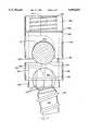
- FIG. 2is a side view of the coupling element of a first embodiment of the present invention.
- FIG. 3is a side view of the locking collar of the present invention, shown along a direction wherein the rod seating grooves thereof are aligned perpendicular to the plane of view.
- FIG. 4is a side view of the coupling element shown in FIG. 2, having the screw shown in FIG. 1 inserted into the interior chamber therein, and including the locking collar shown in FIG. 3 in its unsecured position.
- FIG. 5is a side cross-sectional view of the top locking nut of the present invention.
- FIG. 6is a side view of the rod securing sleeve of the first embodiment, shown along a direction wherein the rod seating grooves thereof are aligned perpendicular to the plane of view.
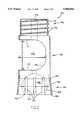
- FIG. 7is a side cross-sectional view of the first embodiment of the present invention in its fully assembled disposition having a rod securely locked therein.
- FIG. 1a side view of the screw portion of the present invention, comprising a curvate head, is shown.
- the screw 120comprises a head portion 122, a neck 124, and a shaft 126.
- the shaft 126is shown as having a tapered shape with a high pitch thread 128. It shall be understood that a variety of shaft designs are interchangeable with the present design. The specific choice of shaft features, such as thread pitch, shaft diameter to thread diameter ratio, and overall shaft shape, should be made be the physician with respect to the conditions of the individual patient's bone, however, this invention is compatible with a wide variety of shaft designs.
- the head portion 122 of the screw 120comprises a semi-spherical shape, which has a recess i30 in it. It is understood that the semi-spherical shape is a section of a sphere, in the embodiment shown the section is greater in extent than a hemisphere, and it correspondingly exhibits an external contour which is equidistant from a center point of the head.
- the major cross-section of the semi-spherical head 122includes at least 270 degrees of a circle.
- the recess 130defines a receiving locus for the application of a torque for driving the screw 120 into the bone.
- the specific shape of the recess 122may be chosen to cooperate with any suitable screw-driving tool.
- the recess 130may comprise a slot for a flat-headed screwdriver, a crossed recess for a phillips head screwdriver, or most preferably, a hexagonally shaped hole for receiving an allen wrench. It is further preferable that the recess 130 be co-axial with the general elongate axis of the screw 120, and most particularly with respect to the shaft 126. Having the axes of the recess 130 and the shaft 126 co-linear facilitates step of inserting the screw 120 into the bone.
- the semi-spherical head portion 122is connected to the shaft 126 at a neck portion 124. While it is preferable that the diameter of the shaft 126 be less than the diameter of the semi-spherical head 122, it is also preferable that the neck 124 of the screw 120 be narrower than the widest portion of the shaft 126. This preferable dimension permits the screw to be locked at a variety of angles while still being securely joined to the coupling element (embodiments of which are shown in FIGS. 2, 3 and 7).
- the coupling element 150comprises a generally cylindrical body which may be conceptually separated into a lower portion 152, an intermediate portion 154, and an upper portion 156, each of which shall be described more fully hereinbelow.
- the exterior surface 158 of the bodyis tapered in the elongate direction such that the body is wider at the bottom 160 of the lower portion 152 than at the top 162 thereof.
- the bottom 160 of the elementincludes an opening 164, defined by annular lip 163, which forms the mouth of an interior chamber 166.
- the diameter of the opening 164when otherwise unaffected by external deflecting forces, is more narrow than the maximum diameter A--A of the interior chamber 166.
- the interior chamber 166has a generally curvate inner surface 168 which is correspondingly shaped to receive the semi-spherical head 122 of the screw 120.
- the exterior surface of the lower portionincludes a series of slots 170 which extend vertically upward from the bottom 160 of the element to a point which is closer to the top 162 of the lower portion 152 than the maximum horizontal diameter A--A.
- the slots 170are provided in order that the application of an external deflecting force may widen or narrow the opening 164 therein permitting the insertion of an object which is iarger than the undefiected diameter of the opening 164, or conversely, providing for the retention of an object which is smaller than the undeflected diameter of the opening 164.
- the intermediate portion 154 of the generally cylindrical body of the coupling element 150includes a large removed section which forms a horizontal channel, therein forming a rod receiving locus 172 in the side of the coupling element 150.
- the channel, or rod receiving locus, 172comprises a curvate inner wall 174.
- the vertical distance from the top 171 of the channel 172 to the bottom 173 thereofis larger than the diameter of the rod which is to be provided therein.
- This distance B--Bis necessarily larger than the diameter of the rod (see FIG. 7) so that the rod may be translated upward and downward within this channel.
- the distance C--C which corresponds to the maximum depth of the channel 172is set such that the support rod which is positioned in the rod receiving locus 172 nests fully within the coupling element 150, and does not extend beyond the lateral extent of the element, which would prevent a rod securing sleeve (such as shall be described with reference to FIGS. 5 and 7) from sliding into retaining relationship with the rod within the rod receiving locus 172.
- the upper portion 156 of the coupling element 150comprises a slightly narrower cylindrical core 175, having a threading 176 thereon.
- the upper portion 156, and the threading 176 thereon,is ideally suited for receiving a top locking nut (see FIG. 3).
- a central bore 178extends through the upper portion 156, through the intermediate portion 154, and into the lower portion 152. (As shown in the embodiment of FIG. 2, the bore 178 may be interrupted across the open spalce of the rod receiving locus 172, however, the passage defined thereby is not interrupted.)
- the bore 178therefore, provides a linear passage through which a user may insert a screw-driving tool to access the interior chamber 166, and any structural elements therein.
- the coupling element 150as described more fully above with respect to FIG. 1, is shown in a side view, wherein the head 122 of the screw 120 has been received within the interior chamber 166, and a locking collar 180 is shown in its pre-locked position about the top 162 of the lower portion 152.
- the head 122 of the screw 120is rotationally free to move relative to the coupling element, however, it is prevented from fully separating from the coupling element and the interior chamber 166 by the annular lip 163 at the bottom 160 of the lower portion 152.
- the locking collar 180comprises a contiguous annular element having an inner diameter which is equal to or slightly larger than the outer diameter of the lower portion 152 at the top 162 thereof.
- the locking collarIn order to lock the screw 120 into an angle relative to the coupling element 150, therein eliminating the freedom of the screw 120 to swing and rotate relative to the coupling element 150, the locking collar must be forced downward relative to the coupling element 150.
- a dowel, protuberance, or other suitable meansmay be provided on the surface of the element 150 so that the collar 180 may not be easily moved upward, thereby preventing separation of the collar during handling and/or shipping, prior to use.
- the top surface 102 of the locking collarincludes a pair of opposing currate grooves 104 on which to receive the rod. It is the downward translation of the rod, as is set forth hereinbelow with reference to FIG. 7, which causes the locking collar 180 to descend and secure the screw 120 to the coupling element 150.
- FIGS. 4, 5, and 6a top locking nut 185, the rod securing sleeve 190, and the locking collar 180 of the first embodiment are shown in respective side cross-section views.
- the nut 185comprises an inner threading 186 which is intended to mate with the threading 176 on the upper portion 156 of the coupling element 150.
- the bottom surface 188 of the nut 185is intended to seat against the top surface 192 of the rod securing sleeve 190, but is permitted to rotate relative to the sleeve, therein providing a means for driving the sleeve downward (as more fully described hereinbelow with respect to the full assembly of the device, and with respect to FIG. 7).
- the sleevecomprises a hollow cylindrical body 194 having an interior diameter which is equal to the outer diameter of the coupling element, so that it may be placed over the coupling element.
- the bottom surface 111 of the rod securing sleeve 190includes diametrically opposing grooves 110 which are positioned and designed to securely mate to the curvature of the rod which is to be positioned within the rod receiving locus 172.
- the locking collar 180as described above with respect to FIG. 3 and the initial disposition of the coupling element prior to implantation, comprises a hollow cylindrical body 181 having a pair of opposing grooves 104.
- the grooves 104 of the locking collar 180are shown as having being a much shallower curve than the grooves 110 of the rod securing sleeve 190. While the radius of curvature of each pair of the grooves 104,110 is the same, it is preferable that the rod securing sleeve grooves 110 be deeper inasmuch as they are designed to lock the rod in place.
- the locking collar 180is further designed to translate downward to lock the screw 120 to the coupling element 150. in order that the bottom lip of the rod receiving locus does not interfere with this downward. translation, the grooves 104 must be shallower.
- the interior surface 183 of the locking collar 180prefferably includes a lower outwardly tapered portion 184 so that the downward translation of the collar 180 relative to the lower portion 152 of the coupling element 150 is not hindered by any binding mechanisms associated with the moving of a sharp angled edge through a distance to engage a friction lock.
- FIG. 7shows a side view of the fully locked coupling element, rod, and screw system
- a pre-driiied holeis provided in the bone, into which it is desired that the screw 120 be disposed.
- the holemay be pre-tapped, or the external threading 128 of the screw 120 may include a self-tapping lead edge.
- the head 122 of the screw 120is inserted into the interior chamber 166 of the coupling element 150.
- the locking collar 180has not yet been forced downward along the outwardly tapered lower portion 152 (as shown in FIG. 3) thereby providing the screw 120 and the coupling element 150 with the capacity to rotate relative to one another.
- the central bore 178may be aligned with the recess 130 in the head 122 of the screw 120 so that a screw-driving tool may be used to drive the screw into the preformed hole in the bone.
- the coupling element 150may be rotated relative to the screw 120, to an angle such that support rod 250 may be properly nested within the rod receiving locus 172, and disposed on the grooves 104 of the locking collar 180.
- the rod securing sleeve 190is dropped over the element, such that the grooves 110 of the sleeve 190 are seated against the top of the rod 250.
- the head 122 and the coupling element 150remain rotationally free, because the locking collar 180 remains positioned at the top 162 of the lower portion 152 of the element.
- the top locking nut 185is threaded onto the upper portion 156 of the coupling element 150.
- the lower surface 188 of the nut 185seats against the top surface 192 of the rod securing sleeve 190.
- the rod securing sleeve 190is driven downward. This motion causes the rod 250 to translate downward therein forcing the locking collar 180 to descend as well.
- the locking collar 180By descending along the tapered lower portion 152 of the element, the locking collar 180 provides an inwardly directed deflecting force which causes the slots 170 in the lower portion 152 of the element to narrow so that the collar may proceed downward. This deflection inward causes the inner surface 168 of the interior chamber 166 to crush lock against the head 122 of the screw 120. This clamping force locks the angulation of the screw 120 to the coupling element 150.
- the downward force of the nut 185 against the rod securing sleeve 190 and the upward resistance of the locking collar 180causes the rod 250 to be locked between the grooves 104,110 of each.
- This lockingprevents the rod 250 from sliding relative to the assembled structure (along an axis which is perpendicular to the plane of FIG. 7).
- the full insertion of the top locking nut 185therefore, locks the rod 250 to the coupling element 150, as well as the screw 120 to the coupling element 150.
Landscapes
- Health & Medical Sciences (AREA)
- Orthopedic Medicine & Surgery (AREA)
- Life Sciences & Earth Sciences (AREA)
- Neurology (AREA)
- Surgery (AREA)
- Heart & Thoracic Surgery (AREA)
- Engineering & Computer Science (AREA)
- Biomedical Technology (AREA)
- Nuclear Medicine, Radiotherapy & Molecular Imaging (AREA)
- Medical Informatics (AREA)
- Molecular Biology (AREA)
- Animal Behavior & Ethology (AREA)
- General Health & Medical Sciences (AREA)
- Public Health (AREA)
- Veterinary Medicine (AREA)
- Surgical Instruments (AREA)
Abstract
Description
Claims (13)
Priority Applications (12)
| Application Number | Priority Date | Filing Date | Title |
|---|---|---|---|
| US08/502,809US5584834A (en) | 1995-07-13 | 1995-07-14 | Polyaxial locking screw and coupling element assembly for use with side loading rod fixation apparatus |
| AT96924414TATE255366T1 (en) | 1995-07-13 | 1996-07-10 | MULTI-AXIS LOCKING MECHANISM |
| DK96924414TDK0837656T3 (en) | 1995-07-13 | 1996-07-10 | Polyaxial locking mechanism |
| KR10-1998-0700223AKR100431091B1 (en) | 1995-07-13 | 1996-07-10 | Multilock fixture |
| JP50596697AJP3845448B2 (en) | 1995-07-13 | 1996-07-10 | Multi-axis direction fixing mechanism |
| DE69630957TDE69630957T2 (en) | 1995-07-13 | 1996-07-10 | MULTI-AXIS LOCKING MECHANISM |
| EP96924414AEP0837656B1 (en) | 1995-07-13 | 1996-07-10 | A polyaxial locking mechanism |
| CA002225044ACA2225044C (en) | 1995-07-13 | 1996-07-10 | A polyaxial locking mechanism |
| AU64594/96AAU6459496A (en) | 1995-07-13 | 1996-07-10 | A polyaxial locking mechanism |
| PCT/US1996/011503WO1997002786A1 (en) | 1995-07-13 | 1996-07-10 | A polyaxial locking mechanism |
| PT96924414TPT837656E (en) | 1995-07-13 | 1996-07-10 | POLYXIAL LOCKING MECHANISM FOR CONTROL OF A CELLULAR RADIO COMMUNICATION NETWORK THROUGH A SET OF PROTOCOL ANALYZERS AND MOBILE STAKES |
| ES96924414TES2211964T3 (en) | 1995-07-13 | 1996-07-10 | MECHANISMS OF POLIAXIAL LOCK. |
Applications Claiming Priority (2)
| Application Number | Priority Date | Filing Date | Title |
|---|---|---|---|
| US08/502,285US5549608A (en) | 1995-07-13 | 1995-07-13 | Advanced polyaxial locking screw and coupling element device for use with rod fixation apparatus |
| US08/502,809US5584834A (en) | 1995-07-13 | 1995-07-14 | Polyaxial locking screw and coupling element assembly for use with side loading rod fixation apparatus |
Related Parent Applications (1)
| Application Number | Title | Priority Date | Filing Date |
|---|---|---|---|
| US08/502,285Continuation-In-PartUS5549608A (en) | 1995-07-13 | 1995-07-13 | Advanced polyaxial locking screw and coupling element device for use with rod fixation apparatus |
Publications (1)
| Publication Number | Publication Date |
|---|---|
| US5584834Atrue US5584834A (en) | 1996-12-17 |
Family
ID=46249814
Family Applications (1)
| Application Number | Title | Priority Date | Filing Date |
|---|---|---|---|
| US08/502,809Expired - LifetimeUS5584834A (en) | 1995-07-13 | 1995-07-14 | Polyaxial locking screw and coupling element assembly for use with side loading rod fixation apparatus |
Country Status (1)
| Country | Link |
|---|---|
| US (1) | US5584834A (en) |
Cited By (238)
| Publication number | Priority date | Publication date | Assignee | Title |
|---|---|---|---|---|
| US5728098A (en)* | 1996-11-07 | 1998-03-17 | Sdgi Holdings, Inc. | Multi-angle bone screw assembly using shape-memory technology |
| US5797911A (en)* | 1996-09-24 | 1998-08-25 | Sdgi Holdings, Inc. | Multi-axial bone screw assembly |
| US5879350A (en)* | 1996-09-24 | 1999-03-09 | Sdgi Holdings, Inc. | Multi-axial bone screw assembly |
| US5885286A (en)* | 1996-09-24 | 1999-03-23 | Sdgi Holdings, Inc. | Multi-axial bone screw assembly |
| US5891145A (en)* | 1997-07-14 | 1999-04-06 | Sdgi Holdings, Inc. | Multi-axial screw |
| US5928243A (en) | 1997-07-16 | 1999-07-27 | Spinal Concepts, Inc. | Pedicle probe and depth gage |
| US5935133A (en) | 1997-08-26 | 1999-08-10 | Spinal Concepts, Inc. | Surgical cable system and method |
| US5961516A (en)* | 1996-08-01 | 1999-10-05 | Graf; Henry | Device for mechanically connecting and assisting vertebrae with respect to one another |
| US5989250A (en) | 1996-10-24 | 1999-11-23 | Spinal Concepts, Inc. | Method and apparatus for spinal fixation |
| US6030389A (en) | 1997-08-04 | 2000-02-29 | Spinal Concepts, Inc. | System and method for stabilizing the human spine with a bone plate |
| WO2000018310A1 (en) | 1998-09-29 | 2000-04-06 | Synthes Ag Chur | Device for joining a longitudinal support and bone fixation means |
| US6053921A (en) | 1997-08-26 | 2000-04-25 | Spinal Concepts, Inc. | Surgical cable system and method |
| US6063090A (en)* | 1996-12-12 | 2000-05-16 | Synthes (U.S.A.) | Device for connecting a longitudinal support to a pedicle screw |
| US6080193A (en) | 1997-05-01 | 2000-06-27 | Spinal Concepts, Inc. | Adjustable height fusion device |
| US6132430A (en)* | 1996-10-24 | 2000-10-17 | Spinal Concepts, Inc. | Spinal fixation system |
| US6162234A (en)* | 1993-03-23 | 2000-12-19 | Freedland; Yosef | Adjustable button cinch anchor orthopedic fastener |
| US6171311B1 (en)* | 1996-10-18 | 2001-01-09 | Marc Richelsoph | Transverse connector |
| US6187005B1 (en) | 1998-09-11 | 2001-02-13 | Synthes (Usa) | Variable angle spinal fixation system |
| US6248105B1 (en) | 1997-05-17 | 2001-06-19 | Synthes (U.S.A.) | Device for connecting a longitudinal support with a pedicle screw |
| US6254602B1 (en)* | 1999-05-28 | 2001-07-03 | Sdgi Holdings, Inc. | Advanced coupling device using shape-memory technology |
| US6258089B1 (en)* | 1998-05-19 | 2001-07-10 | Alphatec Manufacturing, Inc. | Anterior cervical plate and fixation system |
| US6280442B1 (en) | 1999-09-01 | 2001-08-28 | Sdgi Holdings, Inc. | Multi-axial bone screw assembly |
| US6371957B1 (en) | 1997-01-22 | 2002-04-16 | Synthes (Usa) | Device for connecting a longitudinal bar to a pedicle screw |
| US6413258B1 (en) | 1999-08-12 | 2002-07-02 | Osteotech, Inc. | Rod-to-rod coupler |
| US20020111628A1 (en)* | 2001-02-15 | 2002-08-15 | Ralph James D. | Polyaxial pedicle screw having a rotating locking element |
| US6454769B2 (en) | 1997-08-04 | 2002-09-24 | Spinal Concepts, Inc. | System and method for stabilizing the human spine with a bone plate |
| US6485491B1 (en) | 2000-09-15 | 2002-11-26 | Sdgi Holdings, Inc. | Posterior fixation system |
| WO2003068086A1 (en)* | 2002-02-11 | 2003-08-21 | Synthes Ag Chur | Device for linking a longitudinal support with a bone |
| WO2003032863A3 (en)* | 2001-10-15 | 2003-10-02 | Gary J Reed | Orthopedic stabilization device and method |
| US6692500B2 (en)* | 2001-10-15 | 2004-02-17 | Gary Jack Reed | Orthopedic stabilization device and method |
| US6740086B2 (en) | 2002-04-18 | 2004-05-25 | Spinal Innovations, Llc | Screw and rod fixation assembly and device |
| US20040111088A1 (en)* | 2002-12-06 | 2004-06-10 | Picetti George D. | Multi-rod bone attachment member |
| US6770075B2 (en) | 2001-05-17 | 2004-08-03 | Robert S. Howland | Spinal fixation apparatus with enhanced axial support and methods for use |
| US20040193161A1 (en)* | 2001-10-03 | 2004-09-30 | Vaughan Paul A. | Vertebral stabilization assembly and method |
| US6800079B2 (en)* | 2002-03-15 | 2004-10-05 | Lock-N-Stitch, Inc. | Orthopedic stabilization device and method |
| US6800078B2 (en)* | 2001-11-07 | 2004-10-05 | Lock-N-Stitch, Inc. | Orthopedic stabilization device and method |
| US20050080415A1 (en)* | 2003-10-14 | 2005-04-14 | Keyer Thomas R. | Polyaxial bone anchor and method of spinal fixation |
| US20050096653A1 (en)* | 2003-11-03 | 2005-05-05 | Doubler Robert L. | Bone fixation system with low profile fastener |
| US6893443B2 (en) | 1999-07-07 | 2005-05-17 | Synthes (U.S.A) | Angle-adjustable bone screw and fixation device |
| US20050187548A1 (en)* | 2004-01-13 | 2005-08-25 | Butler Michael S. | Pedicle screw constructs for spine fixation systems |
| US6945972B2 (en) | 2000-08-24 | 2005-09-20 | Synthes | Apparatus for connecting a bone fastener to a longitudinal rod |
| US20050234452A1 (en)* | 2004-04-16 | 2005-10-20 | Malandain Hugues F | Subcutaneous support |
| US20050234451A1 (en)* | 2004-04-16 | 2005-10-20 | Markworth Aaron D | Pedicle screw assembly |
| US20050234456A1 (en)* | 2004-04-16 | 2005-10-20 | Malandain Hugues F | Plate system for minimally invasive support of the spine |
| US6964664B2 (en) | 2000-01-06 | 2005-11-15 | Spinal Concepts Inc. | System and method for stabilizing the human spine with a bone plate |
| US20060095038A1 (en)* | 2004-11-03 | 2006-05-04 | Jackson Roger P | Polyaxial bone screw |
| US20060100622A1 (en)* | 2004-11-10 | 2006-05-11 | Jackson Roger P | Polyaxial bone screw with helically wound capture connection |
| US20060100621A1 (en)* | 2004-11-10 | 2006-05-11 | Jackson Roger P | Polyaxial bone screw with discontinuous helically wound capture connection |
| US20060116687A1 (en)* | 2004-11-30 | 2006-06-01 | Miller Keith E | Side-loading adjustable bone anchor |
| US20060116677A1 (en)* | 2004-12-01 | 2006-06-01 | Burd Brian A | Side-loading bone anchor |
| US20060264933A1 (en)* | 2005-05-04 | 2006-11-23 | Baker Daniel R | Multistage spinal fixation locking mechanism |
| US20060276789A1 (en)* | 2005-05-27 | 2006-12-07 | Jackson Roger P | Polyaxial bone screw with shank articulation pressure insert and method |
| WO2007041698A1 (en)* | 2005-10-04 | 2007-04-12 | Alphaspine, Inc. | Modular pedicle screw systems and methods of intra-operatively assembling the same |
| US20070093819A1 (en)* | 2005-09-19 | 2007-04-26 | Albert Todd J | Bone screw apparatus, system and method |
| US20070161995A1 (en)* | 2005-10-06 | 2007-07-12 | Trautwein Frank T | Polyaxial Screw |
| US20070270807A1 (en)* | 2006-04-10 | 2007-11-22 | Sdgi Holdings, Inc. | Multi-piece circumferential retaining ring |
| US7314467B2 (en) | 2002-04-24 | 2008-01-01 | Medical Device Advisory Development Group, Llc. | Multi selective axis spinal fixation system |
| US20080004626A1 (en)* | 2006-05-26 | 2008-01-03 | Glazer Paul A | Orthopedic coil screw insert |
| US7316684B1 (en)* | 1999-07-22 | 2008-01-08 | Stryker Spine | Multiaxial connection for osteosynthesis |
| US7338491B2 (en) | 2005-03-22 | 2008-03-04 | Spinefrontier Inc | Spinal fixation locking mechanism |
| US20080119857A1 (en)* | 2006-11-16 | 2008-05-22 | Spine Wave, Inc. | Multi-Axial Spinal Fixation System |
| US20080183220A1 (en)* | 2007-01-19 | 2008-07-31 | Glazer Paul A | Orthopedic screw insert |
| US7476239B2 (en) | 2005-05-10 | 2009-01-13 | Jackson Roger P | Polyaxial bone screw with compound articulation |
| US20090062857A1 (en)* | 2007-08-31 | 2009-03-05 | Ramsay Christopher L | Minimally invasive guide system |
| US20090062858A1 (en)* | 2007-08-31 | 2009-03-05 | Sara Dziedzic | Methods and instruments for approximating misaligned |
| US20090062859A1 (en)* | 2007-08-31 | 2009-03-05 | Michael Mahoney | Method and system for securing a rod to a bone anchor with a connector |
| US20090062864A1 (en)* | 2007-08-31 | 2009-03-05 | Steven Ludwig | Offset connection bone anchor assembly |
| US20090062822A1 (en)* | 2007-08-31 | 2009-03-05 | Frasier William J | Adaptable clamping mechanism for coupling a spinal fixation element to a bone anchor |
| US20090069852A1 (en)* | 2007-09-06 | 2009-03-12 | Warsaw Orthopedic, Inc. | Multi-Axial Bone Anchor Assembly |
| US7507248B2 (en) | 2001-04-06 | 2009-03-24 | Ldr Medical | Spinal osteosynthesis device and preparation method |
| US20090105756A1 (en)* | 2007-10-23 | 2009-04-23 | Marc Richelsoph | Spinal implant |
| US7578849B2 (en) | 2006-01-27 | 2009-08-25 | Warsaw Orthopedic, Inc. | Intervertebral implants and methods of use |
| US20090254125A1 (en)* | 2008-04-03 | 2009-10-08 | Daniel Predick | Top Loading Polyaxial Spine Screw Assembly With One Step Lockup |
| US20090264933A1 (en)* | 2008-04-22 | 2009-10-22 | Warsaw Orthopedic, Inc. | Anchors for securing a rod to a vertebral member |
| US7608096B2 (en) | 2003-03-10 | 2009-10-27 | Warsaw Orthopedic, Inc. | Posterior pedicle screw and plate system and methods |
| US20090275986A1 (en)* | 2008-05-05 | 2009-11-05 | Warsaw Orthopedic, Inc. | Flexible spinal stabilization element and system |
| US20090299414A1 (en)* | 2003-04-09 | 2009-12-03 | Jackson Roger P | Polyaxial bone screw with uploaded threaded shank and method of assembly and use |
| US7637952B2 (en) | 2002-03-11 | 2009-12-29 | Zimmer Spine, Inc. | Instrumentation and procedure for implanting spinal implant devices |
| US7662175B2 (en) | 2003-06-18 | 2010-02-16 | Jackson Roger P | Upload shank swivel head bone screw spinal implant |
| US7682376B2 (en) | 2006-01-27 | 2010-03-23 | Warsaw Orthopedic, Inc. | Interspinous devices and methods of use |
| US20100160976A1 (en)* | 2008-12-23 | 2010-06-24 | Lutz Biedermann | Receiving part for receiving a rod for coupling the rod to a bone anchoring element and a bone anchoring device with such a receiving part |
| US20100160978A1 (en)* | 2008-12-23 | 2010-06-24 | John Carbone | Bone screw assembly with non-uniform material |
| US20100168800A1 (en)* | 2008-12-30 | 2010-07-01 | Lutz Biedermann | Receiving part for receiving a rod for coupling the rod to a bone anchoring element and a bone anchoring device with such a receiving part |
| US20100168801A1 (en)* | 2008-12-29 | 2010-07-01 | Lutz Biedermann | Receiving part for receiving a rod for coupling the rod to a bone anchoring element and bone anchoring device with such a receiving part |
| US7766947B2 (en) | 2001-10-31 | 2010-08-03 | Ortho Development Corporation | Cervical plate for stabilizing the human spine |
| US7766915B2 (en) | 2004-02-27 | 2010-08-03 | Jackson Roger P | Dynamic fixation assemblies with inner core and outer coil-like member |
| US7766945B2 (en) | 2004-08-10 | 2010-08-03 | Lanx, Inc. | Screw and rod fixation system |
| US20100222822A1 (en)* | 2002-08-28 | 2010-09-02 | Warsaw Orthopedic, Inc. | Posterior Fixation System |
| US7789896B2 (en) | 2005-02-22 | 2010-09-07 | Jackson Roger P | Polyaxial bone screw assembly |
| US7789899B2 (en) | 2004-12-30 | 2010-09-07 | Warsaw Orthopedic, Inc. | Bone anchorage screw with built-in hinged plate |
| US7811311B2 (en) | 2004-12-30 | 2010-10-12 | Warsaw Orthopedic, Inc. | Screw with deployable interlaced dual rods |
| US7815663B2 (en) | 2006-01-27 | 2010-10-19 | Warsaw Orthopedic, Inc. | Vertebral rods and methods of use |
| US20100312288A1 (en)* | 2007-05-16 | 2010-12-09 | Hammill Sr John E | Thread-thru polyaxial pedicle screw system |
| US20110009911A1 (en)* | 2008-11-14 | 2011-01-13 | Hammill Sr John E | Locking polyaxial ball and socket fastener |
| US7875065B2 (en) | 2004-11-23 | 2011-01-25 | Jackson Roger P | Polyaxial bone screw with multi-part shank retainer and pressure insert |
| US7896902B2 (en) | 2006-04-05 | 2011-03-01 | Dong Myung Jeon | Multi-axial double locking bone screw assembly |
| US7901437B2 (en) | 2007-01-26 | 2011-03-08 | Jackson Roger P | Dynamic stabilization member with molded connection |
| US7942910B2 (en) | 2007-05-16 | 2011-05-17 | Ortho Innovations, Llc | Polyaxial bone screw |
| US7942911B2 (en) | 2007-05-16 | 2011-05-17 | Ortho Innovations, Llc | Polyaxial bone screw |
| US7942909B2 (en) | 2009-08-13 | 2011-05-17 | Ortho Innovations, Llc | Thread-thru polyaxial pedicle screw system |
| US7947065B2 (en) | 2008-11-14 | 2011-05-24 | Ortho Innovations, Llc | Locking polyaxial ball and socket fastener |
| US7951170B2 (en) | 2007-05-31 | 2011-05-31 | Jackson Roger P | Dynamic stabilization connecting member with pre-tensioned solid core |
| US7951173B2 (en) | 2007-05-16 | 2011-05-31 | Ortho Innovations, Llc | Pedicle screw implant system |
| US7967850B2 (en) | 2003-06-18 | 2011-06-28 | Jackson Roger P | Polyaxial bone anchor with helical capture connection, insert and dual locking assembly |
| US7993373B2 (en) | 2005-02-22 | 2011-08-09 | Hoy Robert W | Polyaxial orthopedic fastening apparatus |
| US8012177B2 (en) | 2007-02-12 | 2011-09-06 | Jackson Roger P | Dynamic stabilization assembly with frusto-conical connection |
| US8021397B2 (en) | 2003-08-20 | 2011-09-20 | Warsaw Orthopedic, Inc. | Multi-axial orthopedic device and system |
| US20110251643A1 (en)* | 2008-10-23 | 2011-10-13 | Lotfi Miladi | Spinal Osteosynthesis System |
| US8057518B2 (en) | 2007-08-31 | 2011-11-15 | Depuy Spine, Inc. | Spanning connector for connecting a spinal fixation element and an offset bone anchor |
| US8066739B2 (en) | 2004-02-27 | 2011-11-29 | Jackson Roger P | Tool system for dynamic spinal implants |
| US8092500B2 (en) | 2007-05-01 | 2012-01-10 | Jackson Roger P | Dynamic stabilization connecting member with floating core, compression spacer and over-mold |
| US8100915B2 (en) | 2004-02-27 | 2012-01-24 | Jackson Roger P | Orthopedic implant rod reduction tool set and method |
| US8105368B2 (en) | 2005-09-30 | 2012-01-31 | Jackson Roger P | Dynamic stabilization connecting member with slitted core and outer sleeve |
| US8118840B2 (en) | 2009-02-27 | 2012-02-21 | Warsaw Orthopedic, Inc. | Vertebral rod and related method of manufacture |
| US8128667B2 (en) | 2002-09-06 | 2012-03-06 | Jackson Roger P | Anti-splay medical implant closure with multi-surface removal aperture |
| US8137386B2 (en) | 2003-08-28 | 2012-03-20 | Jackson Roger P | Polyaxial bone screw apparatus |
| US8152810B2 (en) | 2004-11-23 | 2012-04-10 | Jackson Roger P | Spinal fixation tool set and method |
| US8162988B2 (en) | 2001-10-18 | 2012-04-24 | Ldr Medical | Plate for osteosynthesis device and method of preassembling such device |
| US8197517B1 (en) | 2007-05-08 | 2012-06-12 | Theken Spine, Llc | Frictional polyaxial screw assembly |
| US20120179209A1 (en)* | 2010-12-10 | 2012-07-12 | Lutz Biedermann | Receiving part for receiving a rod for coupling the rod to a bone anchoring element and a bone anchoring device |
| US20120179211A1 (en)* | 2010-12-10 | 2012-07-12 | Lutz Biedermann | Receiving part for receiving a rod for coupling the rod to a bone anchoring element and bone anchoring device with such a receiving part |
| US8221457B2 (en) | 2001-10-18 | 2012-07-17 | Ldr Medical | Progressive approach osteosynthesis device and preassembly method |
| US8241341B2 (en) | 2009-03-20 | 2012-08-14 | Spinal Usa, Inc. | Pedicle screws and methods of using the same |
| US8257398B2 (en) | 2003-06-18 | 2012-09-04 | Jackson Roger P | Polyaxial bone screw with cam capture |
| US8257402B2 (en) | 2002-09-06 | 2012-09-04 | Jackson Roger P | Closure for rod receiving orthopedic implant having left handed thread removal |
| US8273109B2 (en) | 2002-09-06 | 2012-09-25 | Jackson Roger P | Helical wound mechanically interlocking mating guide and advancement structure |
| US8292926B2 (en) | 2005-09-30 | 2012-10-23 | Jackson Roger P | Dynamic stabilization connecting member with elastic core and outer sleeve |
| US8308782B2 (en) | 2004-11-23 | 2012-11-13 | Jackson Roger P | Bone anchors with longitudinal connecting member engaging inserts and closures for fixation and optional angulation |
| US8343219B2 (en) | 2007-06-08 | 2013-01-01 | Ldr Medical | Intersomatic cage, intervertebral prosthesis, anchoring device and implantation instruments |
| US8353932B2 (en) | 2005-09-30 | 2013-01-15 | Jackson Roger P | Polyaxial bone anchor assembly with one-piece closure, pressure insert and plastic elongate member |
| US8366745B2 (en) | 2007-05-01 | 2013-02-05 | Jackson Roger P | Dynamic stabilization assembly having pre-compressed spacers with differential displacements |
| US8366753B2 (en) | 2003-06-18 | 2013-02-05 | Jackson Roger P | Polyaxial bone screw assembly with fixed retaining structure |
| US8377102B2 (en) | 2003-06-18 | 2013-02-19 | Roger P. Jackson | Polyaxial bone anchor with spline capture connection and lower pressure insert |
| US8377100B2 (en) | 2000-12-08 | 2013-02-19 | Roger P. Jackson | Closure for open-headed medical implant |
| US8388666B2 (en) | 2007-09-27 | 2013-03-05 | Biomet C.V. | Locking screw system with relatively hard spiked polyaxial bushing |
| US8388660B1 (en) | 2006-08-01 | 2013-03-05 | Samy Abdou | Devices and methods for superior fixation of orthopedic devices onto the vertebral column |
| US8398682B2 (en) | 2003-06-18 | 2013-03-19 | Roger P. Jackson | Polyaxial bone screw assembly |
| US8444681B2 (en) | 2009-06-15 | 2013-05-21 | Roger P. Jackson | Polyaxial bone anchor with pop-on shank, friction fit retainer and winged insert |
| US8475498B2 (en) | 2007-01-18 | 2013-07-02 | Roger P. Jackson | Dynamic stabilization connecting member with cord connection |
| US8480715B2 (en) | 2007-05-22 | 2013-07-09 | Zimmer Spine, Inc. | Spinal implant system and method |
| US8545538B2 (en) | 2005-12-19 | 2013-10-01 | M. Samy Abdou | Devices and methods for inter-vertebral orthopedic device placement |
| US8556938B2 (en) | 2009-06-15 | 2013-10-15 | Roger P. Jackson | Polyaxial bone anchor with non-pivotable retainer and pop-on shank, some with friction fit |
| US8591515B2 (en) | 2004-11-23 | 2013-11-26 | Roger P. Jackson | Spinal fixation tool set and method |
| US20140018867A1 (en)* | 2011-02-04 | 2014-01-16 | Stefan Freudiger | Precaution against jamming on open bone screws |
| US20140031880A1 (en)* | 2012-07-27 | 2014-01-30 | Biedermann Technologies Gmbh & Co. Kg | Polyaxial bone anchoring device with enlarged pivot angle |
| US8663298B2 (en) | 2007-07-20 | 2014-03-04 | DePuy Synthes Products, LLC | Polyaxial bone fixation element |
| US20140228889A1 (en)* | 2002-02-13 | 2014-08-14 | Zimmer Spine, Inc. | Methods for connecting a longitudinal member to a bone portion |
| US8814911B2 (en) | 2003-06-18 | 2014-08-26 | Roger P. Jackson | Polyaxial bone screw with cam connection and lock and release insert |
| US8814913B2 (en) | 2002-09-06 | 2014-08-26 | Roger P Jackson | Helical guide and advancement flange with break-off extensions |
| US8821546B2 (en) | 2007-11-06 | 2014-09-02 | Stanus Investments, Inc. | Vertebral screw arrangement with locking pin |
| US8845691B2 (en) | 2003-09-01 | 2014-09-30 | Ldr Medical | Osseous anchoring implant with a polyaxial head and method for installing the implant |
| US8845649B2 (en) | 2004-09-24 | 2014-09-30 | Roger P. Jackson | Spinal fixation tool set and method for rod reduction and fastener insertion |
| US8852239B2 (en) | 2013-02-15 | 2014-10-07 | Roger P Jackson | Sagittal angle screw with integral shank and receiver |
| US8870928B2 (en) | 2002-09-06 | 2014-10-28 | Roger P. Jackson | Helical guide and advancement flange with radially loaded lip |
| US8882817B2 (en) | 2010-08-20 | 2014-11-11 | K2M, Inc. | Spinal fixation system |
| US8911477B2 (en) | 2007-10-23 | 2014-12-16 | Roger P. Jackson | Dynamic stabilization member with end plate support and cable core extension |
| US8911478B2 (en) | 2012-11-21 | 2014-12-16 | Roger P. Jackson | Splay control closure for open bone anchor |
| US8911479B2 (en) | 2012-01-10 | 2014-12-16 | Roger P. Jackson | Multi-start closures for open implants |
| US8926672B2 (en) | 2004-11-10 | 2015-01-06 | Roger P. Jackson | Splay control closure for open bone anchor |
| US8926670B2 (en) | 2003-06-18 | 2015-01-06 | Roger P. Jackson | Polyaxial bone screw assembly |
| US8940024B2 (en) | 2007-07-31 | 2015-01-27 | Biedermann Technologies Gmbh & Co. Kg | Bone anchoring device |
| US8979898B2 (en) | 2013-02-20 | 2015-03-17 | K2M, Inc. | Iliosacral polyaxial screw |
| US8979904B2 (en) | 2007-05-01 | 2015-03-17 | Roger P Jackson | Connecting member with tensioned cord, low profile rigid sleeve and spacer with torsion control |
| US8998959B2 (en) | 2009-06-15 | 2015-04-07 | Roger P Jackson | Polyaxial bone anchors with pop-on shank, fully constrained friction fit retainer and lock and release insert |
| US8998961B1 (en) | 2009-02-26 | 2015-04-07 | Lanx, Inc. | Spinal rod connector and methods |
| US9011494B2 (en) | 2009-09-24 | 2015-04-21 | Warsaw Orthopedic, Inc. | Composite vertebral rod system and methods of use |
| US9044272B2 (en) | 2009-11-09 | 2015-06-02 | Ebi, Llc | Multiplanar bone anchor system |
| US9050139B2 (en) | 2004-02-27 | 2015-06-09 | Roger P. Jackson | Orthopedic implant rod reduction tool set and method |
| US9050148B2 (en) | 2004-02-27 | 2015-06-09 | Roger P. Jackson | Spinal fixation tool attachment structure |
| US9084634B1 (en) | 2010-07-09 | 2015-07-21 | Theken Spine, Llc | Uniplanar screw |
| US9101426B2 (en) | 2012-10-11 | 2015-08-11 | Stryker Trauma Sa | Cable plug |
| US9168069B2 (en) | 2009-06-15 | 2015-10-27 | Roger P. Jackson | Polyaxial bone anchor with pop-on shank and winged insert with lower skirt for engaging a friction fit retainer |
| US9198695B2 (en) | 2010-08-30 | 2015-12-01 | Zimmer Spine, Inc. | Polyaxial pedicle screw |
| US9216041B2 (en) | 2009-06-15 | 2015-12-22 | Roger P. Jackson | Spinal connecting members with tensioned cords and rigid sleeves for engaging compression inserts |
| US9216039B2 (en) | 2004-02-27 | 2015-12-22 | Roger P. Jackson | Dynamic spinal stabilization assemblies, tool set and method |
| US9241739B2 (en) | 2008-09-12 | 2016-01-26 | DePuy Synthes Products, Inc. | Spinal stabilizing and guiding fixation system |
| US9282998B2 (en) | 2008-09-05 | 2016-03-15 | DePuy Synthes Products, Inc. | Bone fixation assembly |
| US9320546B2 (en) | 2008-09-29 | 2016-04-26 | DePuy Synthes Products, Inc. | Polyaxial bottom-loading screw and rod assembly |
| US9326796B2 (en) | 2008-11-03 | 2016-05-03 | DePuy Synthes Products, Inc. | Uni-planer bone fixation assembly |
| US9326795B2 (en) | 2001-12-12 | 2016-05-03 | Ldr Medical | Implant for osseous anchoring with polyaxial head |
| US9393049B2 (en) | 2010-08-20 | 2016-07-19 | K2M, Inc. | Spinal fixation system |
| US9414863B2 (en) | 2005-02-22 | 2016-08-16 | Roger P. Jackson | Polyaxial bone screw with spherical capture, compression insert and alignment and retention structures |
| US9421041B2 (en) | 2008-09-09 | 2016-08-23 | Marc E. Richelsoph | Polyaxial screw assembly |
| US9439681B2 (en) | 2007-07-20 | 2016-09-13 | DePuy Synthes Products, Inc. | Polyaxial bone fixation element |
| US9453526B2 (en) | 2013-04-30 | 2016-09-27 | Degen Medical, Inc. | Bottom-loading anchor assembly |
| US9451989B2 (en) | 2007-01-18 | 2016-09-27 | Roger P Jackson | Dynamic stabilization members with elastic and inelastic sections |
| US9451993B2 (en) | 2014-01-09 | 2016-09-27 | Roger P. Jackson | Bi-radial pop-on cervical bone anchor |
| US9480517B2 (en) | 2009-06-15 | 2016-11-01 | Roger P. Jackson | Polyaxial bone anchor with pop-on shank, shank, friction fit retainer, winged insert and low profile edge lock |
| US9510862B2 (en) | 2009-06-17 | 2016-12-06 | DePuy Synthes Products, Inc. | Revision connector for spinal constructs |
| US9526531B2 (en) | 2013-10-07 | 2016-12-27 | Intelligent Implant Systems, Llc | Polyaxial plate rod system and surgical procedure |
| US9566092B2 (en) | 2013-10-29 | 2017-02-14 | Roger P. Jackson | Cervical bone anchor with collet retainer and outer locking sleeve |
| US9597119B2 (en) | 2014-06-04 | 2017-03-21 | Roger P. Jackson | Polyaxial bone anchor with polymer sleeve |
| US9615862B1 (en) | 2015-11-20 | 2017-04-11 | Spinal Llc | Modular head inserter |
| US9649142B2 (en) | 2015-03-10 | 2017-05-16 | Spinal Llc | Modular head assembly |
| US9649135B2 (en) | 2013-11-27 | 2017-05-16 | Spinal Llc | Bottom loading low profile fixation system |
| US9668771B2 (en) | 2009-06-15 | 2017-06-06 | Roger P Jackson | Soft stabilization assemblies with off-set connector |
| US9675389B2 (en) | 2009-12-07 | 2017-06-13 | Samy Abdou | Devices and methods for minimally invasive spinal stabilization and instrumentation |
| US9717533B2 (en) | 2013-12-12 | 2017-08-01 | Roger P. Jackson | Bone anchor closure pivot-splay control flange form guide and advancement structure |
| US9848918B2 (en) | 2005-11-21 | 2017-12-26 | DePuy Synthes Products, Inc. | Polyaxial bone anchors with increased angulation |
| US9907574B2 (en) | 2008-08-01 | 2018-03-06 | Roger P. Jackson | Polyaxial bone anchors with pop-on shank, friction fit fully restrained retainer, insert and tool receiving features |
| US9980753B2 (en) | 2009-06-15 | 2018-05-29 | Roger P Jackson | pivotal anchor with snap-in-place insert having rotation blocking extensions |
| US10039578B2 (en) | 2003-12-16 | 2018-08-07 | DePuy Synthes Products, Inc. | Methods and devices for minimally invasive spinal fixation element placement |
| US10058354B2 (en) | 2013-01-28 | 2018-08-28 | Roger P. Jackson | Pivotal bone anchor assembly with frictional shank head seating surfaces |
| US10064658B2 (en) | 2014-06-04 | 2018-09-04 | Roger P. Jackson | Polyaxial bone anchor with insert guides |
| US10105163B2 (en) | 2009-04-15 | 2018-10-23 | DePuy Synthes Products, Inc. | Revision connector for spinal constructs |
| US10194951B2 (en) | 2005-05-10 | 2019-02-05 | Roger P. Jackson | Polyaxial bone anchor with compound articulation and pop-on shank |
| US10258382B2 (en) | 2007-01-18 | 2019-04-16 | Roger P. Jackson | Rod-cord dynamic connection assemblies with slidable bone anchor attachment members along the cord |
| US10299839B2 (en) | 2003-12-16 | 2019-05-28 | Medos International Sárl | Percutaneous access devices and bone anchor assemblies |
| US10349983B2 (en) | 2003-05-22 | 2019-07-16 | Alphatec Spine, Inc. | Pivotal bone anchor assembly with biased bushing for pre-lock friction fit |
| US10363070B2 (en) | 2009-06-15 | 2019-07-30 | Roger P. Jackson | Pivotal bone anchor assemblies with pressure inserts and snap on articulating retainers |
| US10383660B2 (en) | 2007-05-01 | 2019-08-20 | Roger P. Jackson | Soft stabilization assemblies with pretensioned cords |
| US10413331B2 (en) | 2016-12-21 | 2019-09-17 | Spine Wave, Inc. | Spinal stabilization system with head to head cross connector |
| US10499968B2 (en) | 2014-08-08 | 2019-12-10 | Stryker European Holdings I, Llc | Cable plugs for bone plates |
| US10507043B1 (en) | 2017-10-11 | 2019-12-17 | Seaspine Orthopedics Corporation | Collet for a polyaxial screw assembly |
| US10548740B1 (en) | 2016-10-25 | 2020-02-04 | Samy Abdou | Devices and methods for vertebral bone realignment |
| US10575961B1 (en) | 2011-09-23 | 2020-03-03 | Samy Abdou | Spinal fixation devices and methods of use |
| US10603083B1 (en) | 2010-07-09 | 2020-03-31 | Theken Spine, Llc | Apparatus and method for limiting a range of angular positions of a screw |
| US10695105B2 (en) | 2012-08-28 | 2020-06-30 | Samy Abdou | Spinal fixation devices and methods of use |
| US10729469B2 (en) | 2006-01-09 | 2020-08-04 | Roger P. Jackson | Flexible spinal stabilization assembly with spacer having off-axis core member |
| US10857003B1 (en) | 2015-10-14 | 2020-12-08 | Samy Abdou | Devices and methods for vertebral stabilization |
| US10918498B2 (en) | 2004-11-24 | 2021-02-16 | Samy Abdou | Devices and methods for inter-vertebral orthopedic device placement |
| US10973648B1 (en) | 2016-10-25 | 2021-04-13 | Samy Abdou | Devices and methods for vertebral bone realignment |
| US11006982B2 (en) | 2012-02-22 | 2021-05-18 | Samy Abdou | Spinous process fixation devices and methods of use |
| US11173040B2 (en) | 2012-10-22 | 2021-11-16 | Cogent Spine, LLC | Devices and methods for spinal stabilization and instrumentation |
| US11179248B2 (en) | 2018-10-02 | 2021-11-23 | Samy Abdou | Devices and methods for spinal implantation |
| US11229457B2 (en) | 2009-06-15 | 2022-01-25 | Roger P. Jackson | Pivotal bone anchor assembly with insert tool deployment |
| US11234738B2 (en) | 2018-11-16 | 2022-02-01 | Roger P. Jackson | Pivotal bone anchor assembly having a deployable collet insert with internal pressure ring |
| US11419642B2 (en) | 2003-12-16 | 2022-08-23 | Medos International Sarl | Percutaneous access devices and bone anchor assemblies |
| US11464549B2 (en) | 2009-06-15 | 2022-10-11 | Roger P. Jackson | Pivotal bone anchor assembly with horizontal tool engagement grooves and insert with upright arms having flared outer portions |
| US20230039136A1 (en)* | 2021-08-04 | 2023-02-09 | Biedermann Technologies Gmbh & Co. Kg | Coupling device for coupling a rod to a bone anchoring element and method of manufacturing the same |
| US11751918B2 (en) | 2020-03-12 | 2023-09-12 | Biedermann Technologies Gmbh & Co. Kg | Coupling device for use with a bone anchoring element and bone anchoring device with such a coupling device |
| US12114898B2 (en) | 2020-11-19 | 2024-10-15 | K2M, Inc. | Modular head assembly for spinal fixation |
| US20240350786A1 (en)* | 2023-02-14 | 2024-10-24 | ProCell Therapies, LLC | Micro-channeling system |
| US12213704B1 (en) | 2024-06-18 | 2025-02-04 | Complex Spinal, LLC | Modular spinal fixation screw |
| US12245796B1 (en) | 2024-05-14 | 2025-03-11 | Complex Spinal, LLC | Spinal fixation system having a lockable connector |
| US12245794B1 (en) | 2024-05-14 | 2025-03-11 | Complex Spinal, LLC | Spinal fixation system having a low profile lockable connector |
| US12262921B2 (en) | 2020-06-26 | 2025-04-01 | K2M, Inc. | Modular head assembly |
| US12383311B2 (en) | 2010-05-14 | 2025-08-12 | Roger P. Jackson | Pivotal bone anchor assembly and method for use thereof |
Citations (14)
| Publication number | Priority date | Publication date | Assignee | Title |
|---|---|---|---|---|
| US4805602A (en)* | 1986-11-03 | 1989-02-21 | Danninger Medical Technology | Transpedicular screw and rod system |
| US4946458A (en)* | 1986-04-25 | 1990-08-07 | Harms Juergen | Pedicle screw |
| US4987892A (en)* | 1989-04-04 | 1991-01-29 | Krag Martin H | Spinal fixation device |
| US5151103A (en)* | 1987-11-03 | 1992-09-29 | Synthes (U.S.A.) | Point contact bone compression plate |
| US5176680A (en)* | 1990-02-08 | 1993-01-05 | Vignaud Jean Louis | Device for the adjustable fixing of spinal osteosynthesis rods |
| US5190543A (en)* | 1990-11-26 | 1993-03-02 | Synthes (U.S.A.) | Anchoring device |
| US5207678A (en)* | 1989-07-20 | 1993-05-04 | Prufer | Pedicle screw and receiver member therefore |
| US5217497A (en)* | 1990-07-04 | 1993-06-08 | Mehdian Seyed M H | Apparatus for use in the treatment of spinal disorders |
| US5261909A (en)* | 1992-02-18 | 1993-11-16 | Danek Medical, Inc. | Variable angle screw for spinal implant system |
| US5261912A (en)* | 1990-08-21 | 1993-11-16 | Synthes (U.S.A.) | Implant for an osteosynthesis device, in particular for spinal column correction |
| US5306275A (en)* | 1992-12-31 | 1994-04-26 | Bryan Donald W | Lumbar spine fixation apparatus and method |
| US5360431A (en)* | 1990-04-26 | 1994-11-01 | Cross Medical Products | Transpedicular screw system and method of use |
| US5443467A (en)* | 1993-03-10 | 1995-08-22 | Biedermann Motech Gmbh | Bone screw |
| US5480401A (en)* | 1993-02-17 | 1996-01-02 | Psi | Extra-discal inter-vertebral prosthesis for controlling the variations of the inter-vertebral distance by means of a double damper |
- 1995
- 1995-07-14USUS08/502,809patent/US5584834A/ennot_activeExpired - Lifetime
Patent Citations (14)
| Publication number | Priority date | Publication date | Assignee | Title |
|---|---|---|---|---|
| US4946458A (en)* | 1986-04-25 | 1990-08-07 | Harms Juergen | Pedicle screw |
| US4805602A (en)* | 1986-11-03 | 1989-02-21 | Danninger Medical Technology | Transpedicular screw and rod system |
| US5151103A (en)* | 1987-11-03 | 1992-09-29 | Synthes (U.S.A.) | Point contact bone compression plate |
| US4987892A (en)* | 1989-04-04 | 1991-01-29 | Krag Martin H | Spinal fixation device |
| US5207678A (en)* | 1989-07-20 | 1993-05-04 | Prufer | Pedicle screw and receiver member therefore |
| US5176680A (en)* | 1990-02-08 | 1993-01-05 | Vignaud Jean Louis | Device for the adjustable fixing of spinal osteosynthesis rods |
| US5360431A (en)* | 1990-04-26 | 1994-11-01 | Cross Medical Products | Transpedicular screw system and method of use |
| US5217497A (en)* | 1990-07-04 | 1993-06-08 | Mehdian Seyed M H | Apparatus for use in the treatment of spinal disorders |
| US5261912A (en)* | 1990-08-21 | 1993-11-16 | Synthes (U.S.A.) | Implant for an osteosynthesis device, in particular for spinal column correction |
| US5190543A (en)* | 1990-11-26 | 1993-03-02 | Synthes (U.S.A.) | Anchoring device |
| US5261909A (en)* | 1992-02-18 | 1993-11-16 | Danek Medical, Inc. | Variable angle screw for spinal implant system |
| US5306275A (en)* | 1992-12-31 | 1994-04-26 | Bryan Donald W | Lumbar spine fixation apparatus and method |
| US5480401A (en)* | 1993-02-17 | 1996-01-02 | Psi | Extra-discal inter-vertebral prosthesis for controlling the variations of the inter-vertebral distance by means of a double damper |
| US5443467A (en)* | 1993-03-10 | 1995-08-22 | Biedermann Motech Gmbh | Bone screw |
Cited By (525)
| Publication number | Priority date | Publication date | Assignee | Title |
|---|---|---|---|---|
| US6162234A (en)* | 1993-03-23 | 2000-12-19 | Freedland; Yosef | Adjustable button cinch anchor orthopedic fastener |
| US5961516A (en)* | 1996-08-01 | 1999-10-05 | Graf; Henry | Device for mechanically connecting and assisting vertebrae with respect to one another |
| US5797911A (en)* | 1996-09-24 | 1998-08-25 | Sdgi Holdings, Inc. | Multi-axial bone screw assembly |
| US5879350A (en)* | 1996-09-24 | 1999-03-09 | Sdgi Holdings, Inc. | Multi-axial bone screw assembly |
| US5885286A (en)* | 1996-09-24 | 1999-03-23 | Sdgi Holdings, Inc. | Multi-axial bone screw assembly |
| US6053917A (en)* | 1996-09-24 | 2000-04-25 | Sdgi Holdings, Inc. | Multi-axial bone screw assembly |
| US6171311B1 (en)* | 1996-10-18 | 2001-01-09 | Marc Richelsoph | Transverse connector |
| US6132430A (en)* | 1996-10-24 | 2000-10-17 | Spinal Concepts, Inc. | Spinal fixation system |
| US5989250A (en) | 1996-10-24 | 1999-11-23 | Spinal Concepts, Inc. | Method and apparatus for spinal fixation |
| US6562040B1 (en) | 1996-10-24 | 2003-05-13 | Spinal Concepts, Inc. | Spinal fixation system |
| US6595992B1 (en) | 1996-10-24 | 2003-07-22 | Spinal Concepts, Inc. | Method and apparatus for spinal fixation |
| US6416515B1 (en)* | 1996-10-24 | 2002-07-09 | Spinal Concepts, Inc. | Spinal fixation system |
| US6613050B1 (en) | 1996-10-24 | 2003-09-02 | Spinal Concepts, Inc. | Method and apparatus for spinal fixation |
| US5728098A (en)* | 1996-11-07 | 1998-03-17 | Sdgi Holdings, Inc. | Multi-angle bone screw assembly using shape-memory technology |
| US6287311B1 (en) | 1996-11-07 | 2001-09-11 | Sdgi Holdings, Inc. | Multi-angle bone screw assembly using shape-memory technology |
| US5954725A (en)* | 1996-11-07 | 1999-09-21 | Sdgi Holdings, Inc. | Multi-angle bone screw assembly using shape memory technology |
| US6454773B1 (en) | 1996-11-07 | 2002-09-24 | Sdgi Holdings, Inc. | Multi-angle bone screw assembly using shape-memory technology |
| US6132434A (en)* | 1996-11-07 | 2000-10-17 | Sdgi Holdings, Inc. | Multi-angle bone screw assembly using shape-memory technology |
| US6063090A (en)* | 1996-12-12 | 2000-05-16 | Synthes (U.S.A.) | Device for connecting a longitudinal support to a pedicle screw |
| US20030023240A1 (en)* | 1997-01-22 | 2003-01-30 | Synthes (Usa) | Device for connecting a longitudinal bar to a pedicle screw |
| US7022122B2 (en) | 1997-01-22 | 2006-04-04 | Synthes (U.S.A.) | Device for connecting a longitudinal bar to a pedicle screw |
| US20060149244A1 (en)* | 1997-01-22 | 2006-07-06 | Synthes (Usa) | Device for connecting a longitudinal bar to a pedicle screw |
| US6371957B1 (en) | 1997-01-22 | 2002-04-16 | Synthes (Usa) | Device for connecting a longitudinal bar to a pedicle screw |
| US6080193A (en) | 1997-05-01 | 2000-06-27 | Spinal Concepts, Inc. | Adjustable height fusion device |
| US6576016B1 (en) | 1997-05-01 | 2003-06-10 | Spinal Concepts, Inc. | Adjustable height fusion device |
| US6248105B1 (en) | 1997-05-17 | 2001-06-19 | Synthes (U.S.A.) | Device for connecting a longitudinal support with a pedicle screw |
| US5891145A (en)* | 1997-07-14 | 1999-04-06 | Sdgi Holdings, Inc. | Multi-axial screw |
| US5928243A (en) | 1997-07-16 | 1999-07-27 | Spinal Concepts, Inc. | Pedicle probe and depth gage |
| US6454769B2 (en) | 1997-08-04 | 2002-09-24 | Spinal Concepts, Inc. | System and method for stabilizing the human spine with a bone plate |
| US6030389A (en) | 1997-08-04 | 2000-02-29 | Spinal Concepts, Inc. | System and method for stabilizing the human spine with a bone plate |
| US6391030B1 (en) | 1997-08-26 | 2002-05-21 | Spinal Concepts, Inc. | Surgical cable system and method |
| US6682533B1 (en) | 1997-08-26 | 2004-01-27 | Spinal Concepts, Inc. | Surgical cable system and method |
| US5935133A (en) | 1997-08-26 | 1999-08-10 | Spinal Concepts, Inc. | Surgical cable system and method |
| US6053921A (en) | 1997-08-26 | 2000-04-25 | Spinal Concepts, Inc. | Surgical cable system and method |
| US5964769A (en) | 1997-08-26 | 1999-10-12 | Spinal Concepts, Inc. | Surgical cable system and method |
| US6626907B2 (en)* | 1998-05-19 | 2003-09-30 | Alphatec Manufacturing, Inc. | Anterior cervical plate and fixation system |
| US20010041894A1 (en)* | 1998-05-19 | 2001-11-15 | Campbell Christopher M. | Anterior cervical plate and fixation system |
| US6258089B1 (en)* | 1998-05-19 | 2001-07-10 | Alphatec Manufacturing, Inc. | Anterior cervical plate and fixation system |
| US6187005B1 (en) | 1998-09-11 | 2001-02-13 | Synthes (Usa) | Variable angle spinal fixation system |
| US6582436B2 (en) | 1998-09-29 | 2003-06-24 | Synthes (U.S.A.) | Device for connecting a longitudinal support to a bone anchor |
| WO2000018310A1 (en) | 1998-09-29 | 2000-04-06 | Synthes Ag Chur | Device for joining a longitudinal support and bone fixation means |
| AU743783B2 (en)* | 1998-09-29 | 2002-02-07 | Synthes Gmbh | Device for joining a longitudinal support and bone fixation means |
| US6254602B1 (en)* | 1999-05-28 | 2001-07-03 | Sdgi Holdings, Inc. | Advanced coupling device using shape-memory technology |
| US6893443B2 (en) | 1999-07-07 | 2005-05-17 | Synthes (U.S.A) | Angle-adjustable bone screw and fixation device |
| US7316684B1 (en)* | 1999-07-22 | 2008-01-08 | Stryker Spine | Multiaxial connection for osteosynthesis |
| US6413258B1 (en) | 1999-08-12 | 2002-07-02 | Osteotech, Inc. | Rod-to-rod coupler |
| US8529604B2 (en) | 1999-09-01 | 2013-09-10 | Warsaw Orthopedic, Inc. | Multi-axial bone screw assembly |
| US20040116929A1 (en)* | 1999-09-01 | 2004-06-17 | Barker B. Thomas | Multi-axial bone screw assembly |
| US6660004B2 (en) | 1999-09-01 | 2003-12-09 | Sdgi Holdings, Inc. | Multi-axial bone screw assembly |
| US20110071577A1 (en)* | 1999-09-01 | 2011-03-24 | Warsaw Orthopedic, Inc. | Multi-Axial Bone Screw Assembly |
| US8298274B2 (en) | 1999-09-01 | 2012-10-30 | Warsaw Orthopedic, Inc. | Multi-axial bone screw assembly |
| US6280442B1 (en) | 1999-09-01 | 2001-08-28 | Sdgi Holdings, Inc. | Multi-axial bone screw assembly |
| US7727261B2 (en) | 1999-09-01 | 2010-06-01 | Warsaw Orthopedic, Inc. | Multi-axial bone screw assembly |
| US20100198270A1 (en)* | 1999-09-01 | 2010-08-05 | Warsaw Orthopedic, Inc. | Multi-Axial Bone Screw Assembly |
| US6964664B2 (en) | 2000-01-06 | 2005-11-15 | Spinal Concepts Inc. | System and method for stabilizing the human spine with a bone plate |
| US8025677B2 (en) | 2000-01-06 | 2011-09-27 | Zimmer Spine, Inc. | System and method for stabilizing the human spine with a bone plate |
| US20050251141A1 (en)* | 2000-08-24 | 2005-11-10 | Synthes Usa | Apparatus for connecting a bone fastener to a longitudinal rod |
| US6945972B2 (en) | 2000-08-24 | 2005-09-20 | Synthes | Apparatus for connecting a bone fastener to a longitudinal rod |
| US7699872B2 (en) | 2000-09-15 | 2010-04-20 | Warsaw Orthopedic, Inc. | Posterior fixation system |
| US6485491B1 (en) | 2000-09-15 | 2002-11-26 | Sdgi Holdings, Inc. | Posterior fixation system |
| US8377100B2 (en) | 2000-12-08 | 2013-02-19 | Roger P. Jackson | Closure for open-headed medical implant |
| US7722646B2 (en) | 2001-02-15 | 2010-05-25 | K2M, Inc. | Polyaxial pedicle screw having a rotating locking element |
| US6840940B2 (en)* | 2001-02-15 | 2005-01-11 | K2 Medical, Llc | Polyaxial pedicle screw having a rotating locking element |
| US6451021B1 (en)* | 2001-02-15 | 2002-09-17 | Third Millennium Engineering, Llc | Polyaxial pedicle screw having a rotating locking element |
| US20020111628A1 (en)* | 2001-02-15 | 2002-08-15 | Ralph James D. | Polyaxial pedicle screw having a rotating locking element |
| US20050119658A1 (en)* | 2001-02-15 | 2005-06-02 | K2 Medical Llc | Polyaxial pedicle screw having a rotating locking element |
| US6827719B2 (en)* | 2001-02-15 | 2004-12-07 | K2 Medical, Llc | Polyaxial pedicle screw having a rotating locking element |
| US20030191469A1 (en)* | 2001-02-15 | 2003-10-09 | Ralph James D. | Polyaxial pedicle screw having a rotating locking element |
| US7507248B2 (en) | 2001-04-06 | 2009-03-24 | Ldr Medical | Spinal osteosynthesis device and preparation method |
| US6770075B2 (en) | 2001-05-17 | 2004-08-03 | Robert S. Howland | Spinal fixation apparatus with enhanced axial support and methods for use |
| US7713291B2 (en) | 2001-10-03 | 2010-05-11 | Vaughan Medical Technologies, Inc. | Vertebral stabilization assembly and method |
| US20060149243A1 (en)* | 2001-10-03 | 2006-07-06 | Vaughan Paul A | Vertebral stabilization assembly and method |
| US20050240183A1 (en)* | 2001-10-03 | 2005-10-27 | Vaughan Medical Technologies, Inc. | Vertebral stabilization assembly and method |
| US7087056B2 (en) | 2001-10-03 | 2006-08-08 | Vaughan Medical Technologies, Inc. | Vertebral stabilization assembly and method |
| US6899714B2 (en) | 2001-10-03 | 2005-05-31 | Vaughan Medical Technologies, Inc. | Vertebral stabilization assembly and method |
| US20050267473A1 (en)* | 2001-10-03 | 2005-12-01 | Vaughan Paul A | Vertebral stabilization assembly and method with rigid and semi-rigid members |
| US7645280B2 (en) | 2001-10-03 | 2010-01-12 | Vaughan Medical Technologies, Inc. | Vertebral stabilization assembly and method |
| US20040254578A1 (en)* | 2001-10-03 | 2004-12-16 | Vaughan Paul A. | Vertebral stabilization assembly and method |
| US20040193161A1 (en)* | 2001-10-03 | 2004-09-30 | Vaughan Paul A. | Vertebral stabilization assembly and method |
| US7713290B2 (en) | 2001-10-03 | 2010-05-11 | Vaughan Medical Technologies, Inc. | Vertebral stabilization assembly and method |
| WO2003032863A3 (en)* | 2001-10-15 | 2003-10-02 | Gary J Reed | Orthopedic stabilization device and method |
| US6692500B2 (en)* | 2001-10-15 | 2004-02-17 | Gary Jack Reed | Orthopedic stabilization device and method |
| US8221457B2 (en) | 2001-10-18 | 2012-07-17 | Ldr Medical | Progressive approach osteosynthesis device and preassembly method |
| US8162988B2 (en) | 2001-10-18 | 2012-04-24 | Ldr Medical | Plate for osteosynthesis device and method of preassembling such device |
| US7766947B2 (en) | 2001-10-31 | 2010-08-03 | Ortho Development Corporation | Cervical plate for stabilizing the human spine |
| US6800078B2 (en)* | 2001-11-07 | 2004-10-05 | Lock-N-Stitch, Inc. | Orthopedic stabilization device and method |
| US9326795B2 (en) | 2001-12-12 | 2016-05-03 | Ldr Medical | Implant for osseous anchoring with polyaxial head |
| US20050080419A1 (en)* | 2002-02-11 | 2005-04-14 | Synthes U.S.A. | Device for connecting a longitudinal member to a bone |
| US7585315B2 (en) | 2002-02-11 | 2009-09-08 | Synthes Usa, Llc | Device for connecting a longitudinal member to a bone |
| WO2003068086A1 (en)* | 2002-02-11 | 2003-08-21 | Synthes Ag Chur | Device for linking a longitudinal support with a bone |
| US20140228889A1 (en)* | 2002-02-13 | 2014-08-14 | Zimmer Spine, Inc. | Methods for connecting a longitudinal member to a bone portion |
| US10219835B2 (en) | 2002-02-13 | 2019-03-05 | Zimmer Spine, Inc. | Systems and devices for connecting a longitudinal member to a bone portion |
| US9848913B2 (en) | 2002-02-13 | 2017-12-26 | Zimmer Spine, Inc. | Methods for connecting a longitudinal member to a bone portion |
| US7637952B2 (en) | 2002-03-11 | 2009-12-29 | Zimmer Spine, Inc. | Instrumentation and procedure for implanting spinal implant devices |
| US6800079B2 (en)* | 2002-03-15 | 2004-10-05 | Lock-N-Stitch, Inc. | Orthopedic stabilization device and method |
| US6740086B2 (en) | 2002-04-18 | 2004-05-25 | Spinal Innovations, Llc | Screw and rod fixation assembly and device |
| US8409255B2 (en) | 2002-04-18 | 2013-04-02 | Aesculap Implant Systems, Llc | Screw and rod fixation assembly and device |
| US7955363B2 (en) | 2002-04-18 | 2011-06-07 | Aesculap Implant Systems, Llc | Screw and rod fixation assembly and device |
| US7314467B2 (en) | 2002-04-24 | 2008-01-01 | Medical Device Advisory Development Group, Llc. | Multi selective axis spinal fixation system |
| US8512380B2 (en) | 2002-08-28 | 2013-08-20 | Warsaw Orthopedic, Inc. | Posterior fixation system |
| US20100222822A1 (en)* | 2002-08-28 | 2010-09-02 | Warsaw Orthopedic, Inc. | Posterior Fixation System |
| US8591552B2 (en) | 2002-09-06 | 2013-11-26 | Roger P. Jackson | Anti-splay medical implant closure with multi-surface removal aperture |
| US8876868B2 (en) | 2002-09-06 | 2014-11-04 | Roger P. Jackson | Helical guide and advancement flange with radially loaded lip |
| US8870928B2 (en) | 2002-09-06 | 2014-10-28 | Roger P. Jackson | Helical guide and advancement flange with radially loaded lip |
| US8282673B2 (en) | 2002-09-06 | 2012-10-09 | Jackson Roger P | Anti-splay medical implant closure with multi-surface removal aperture |
| US8273109B2 (en) | 2002-09-06 | 2012-09-25 | Jackson Roger P | Helical wound mechanically interlocking mating guide and advancement structure |
| US8257402B2 (en) | 2002-09-06 | 2012-09-04 | Jackson Roger P | Closure for rod receiving orthopedic implant having left handed thread removal |
| US8814913B2 (en) | 2002-09-06 | 2014-08-26 | Roger P Jackson | Helical guide and advancement flange with break-off extensions |
| US8128667B2 (en) | 2002-09-06 | 2012-03-06 | Jackson Roger P | Anti-splay medical implant closure with multi-surface removal aperture |
| US20040111088A1 (en)* | 2002-12-06 | 2004-06-10 | Picetti George D. | Multi-rod bone attachment member |
| US10463412B2 (en) | 2002-12-06 | 2019-11-05 | Warsaw Orthopedic, Inc. | Multi-rod bone attachment member |
| US9615867B2 (en) | 2002-12-06 | 2017-04-11 | Warsaw Orthopedic, Inc. | Multi-rod bone attachment member |
| US7608096B2 (en) | 2003-03-10 | 2009-10-27 | Warsaw Orthopedic, Inc. | Posterior pedicle screw and plate system and methods |
| US20090299414A1 (en)* | 2003-04-09 | 2009-12-03 | Jackson Roger P | Polyaxial bone screw with uploaded threaded shank and method of assembly and use |
| US8540753B2 (en) | 2003-04-09 | 2013-09-24 | Roger P. Jackson | Polyaxial bone screw with uploaded threaded shank and method of assembly and use |
| US8092502B2 (en) | 2003-04-09 | 2012-01-10 | Jackson Roger P | Polyaxial bone screw with uploaded threaded shank and method of assembly and use |
| US10952777B2 (en) | 2003-04-09 | 2021-03-23 | Roger P. Jackson | Pivotal bone screw assembly with receiver having threaded open channel and lower opening |
| US10349983B2 (en) | 2003-05-22 | 2019-07-16 | Alphatec Spine, Inc. | Pivotal bone anchor assembly with biased bushing for pre-lock friction fit |
| USRE46431E1 (en) | 2003-06-18 | 2017-06-13 | Roger P Jackson | Polyaxial bone anchor with helical capture connection, insert and dual locking assembly |
| US7662175B2 (en) | 2003-06-18 | 2010-02-16 | Jackson Roger P | Upload shank swivel head bone screw spinal implant |
| US8814911B2 (en) | 2003-06-18 | 2014-08-26 | Roger P. Jackson | Polyaxial bone screw with cam connection and lock and release insert |
| US9144444B2 (en) | 2003-06-18 | 2015-09-29 | Roger P Jackson | Polyaxial bone anchor with helical capture connection, insert and dual locking assembly |
| US8398682B2 (en) | 2003-06-18 | 2013-03-19 | Roger P. Jackson | Polyaxial bone screw assembly |
| US8926670B2 (en) | 2003-06-18 | 2015-01-06 | Roger P. Jackson | Polyaxial bone screw assembly |
| US8936623B2 (en) | 2003-06-18 | 2015-01-20 | Roger P. Jackson | Polyaxial bone screw assembly |
| US7967850B2 (en) | 2003-06-18 | 2011-06-28 | Jackson Roger P | Polyaxial bone anchor with helical capture connection, insert and dual locking assembly |
| US8377102B2 (en) | 2003-06-18 | 2013-02-19 | Roger P. Jackson | Polyaxial bone anchor with spline capture connection and lower pressure insert |
| US8636769B2 (en) | 2003-06-18 | 2014-01-28 | Roger P. Jackson | Polyaxial bone screw with shank-retainer insert capture |
| US8366753B2 (en) | 2003-06-18 | 2013-02-05 | Jackson Roger P | Polyaxial bone screw assembly with fixed retaining structure |
| US8257396B2 (en) | 2003-06-18 | 2012-09-04 | Jackson Roger P | Polyaxial bone screw with shank-retainer inset capture |
| US8257398B2 (en) | 2003-06-18 | 2012-09-04 | Jackson Roger P | Polyaxial bone screw with cam capture |
| US9610105B2 (en) | 2003-08-20 | 2017-04-04 | Warsaw Orthopedic, Inc. | Multi-axial orthopedic device and system |
| US8021397B2 (en) | 2003-08-20 | 2011-09-20 | Warsaw Orthopedic, Inc. | Multi-axial orthopedic device and system |
| US8137386B2 (en) | 2003-08-28 | 2012-03-20 | Jackson Roger P | Polyaxial bone screw apparatus |
| US8845691B2 (en) | 2003-09-01 | 2014-09-30 | Ldr Medical | Osseous anchoring implant with a polyaxial head and method for installing the implant |
| US20050080415A1 (en)* | 2003-10-14 | 2005-04-14 | Keyer Thomas R. | Polyaxial bone anchor and method of spinal fixation |
| WO2005037067A3 (en)* | 2003-10-14 | 2005-12-22 | Synthes Usa | Polyaxial bone anchor and method of spinal fixation |
| EP2371312A1 (en) | 2003-11-03 | 2011-10-05 | Spinal, LLC | Bone fixation system with low profile fastener |
| USRE42867E1 (en)* | 2003-11-03 | 2011-10-25 | Spinal, Llc | Bone fixation system with low profile fastener |
| US7090674B2 (en) | 2003-11-03 | 2006-08-15 | Spinal, Llc | Bone fixation system with low profile fastener |
| US20050096653A1 (en)* | 2003-11-03 | 2005-05-05 | Doubler Robert L. | Bone fixation system with low profile fastener |
| US10039578B2 (en) | 2003-12-16 | 2018-08-07 | DePuy Synthes Products, Inc. | Methods and devices for minimally invasive spinal fixation element placement |
| US11426216B2 (en) | 2003-12-16 | 2022-08-30 | DePuy Synthes Products, Inc. | Methods and devices for minimally invasive spinal fixation element placement |
| US11419642B2 (en) | 2003-12-16 | 2022-08-23 | Medos International Sarl | Percutaneous access devices and bone anchor assemblies |
| US10299839B2 (en) | 2003-12-16 | 2019-05-28 | Medos International Sárl | Percutaneous access devices and bone anchor assemblies |
| US8092494B2 (en) | 2004-01-13 | 2012-01-10 | Life Spine, Inc. | Pedicle screw constructs for spine fixation systems |
| US20050187548A1 (en)* | 2004-01-13 | 2005-08-25 | Butler Michael S. | Pedicle screw constructs for spine fixation systems |
| US7678137B2 (en) | 2004-01-13 | 2010-03-16 | Life Spine, Inc. | Pedicle screw constructs for spine fixation systems |
| US8292892B2 (en) | 2004-02-27 | 2012-10-23 | Jackson Roger P | Orthopedic implant rod reduction tool set and method |
| US8100915B2 (en) | 2004-02-27 | 2012-01-24 | Jackson Roger P | Orthopedic implant rod reduction tool set and method |
| US8394133B2 (en) | 2004-02-27 | 2013-03-12 | Roger P. Jackson | Dynamic fixation assemblies with inner core and outer coil-like member |
| US9918751B2 (en) | 2004-02-27 | 2018-03-20 | Roger P. Jackson | Tool system for dynamic spinal implants |
| US8377067B2 (en) | 2004-02-27 | 2013-02-19 | Roger P. Jackson | Orthopedic implant rod reduction tool set and method |
| US8894657B2 (en) | 2004-02-27 | 2014-11-25 | Roger P. Jackson | Tool system for dynamic spinal implants |
| US9050148B2 (en) | 2004-02-27 | 2015-06-09 | Roger P. Jackson | Spinal fixation tool attachment structure |
| US10485588B2 (en) | 2004-02-27 | 2019-11-26 | Nuvasive, Inc. | Spinal fixation tool attachment structure |
| US9532815B2 (en) | 2004-02-27 | 2017-01-03 | Roger P. Jackson | Spinal fixation tool set and method |
| US9216039B2 (en) | 2004-02-27 | 2015-12-22 | Roger P. Jackson | Dynamic spinal stabilization assemblies, tool set and method |
| US11147597B2 (en) | 2004-02-27 | 2021-10-19 | Roger P Jackson | Dynamic spinal stabilization assemblies, tool set and method |
| US11291480B2 (en) | 2004-02-27 | 2022-04-05 | Nuvasive, Inc. | Spinal fixation tool attachment structure |
| US9662151B2 (en) | 2004-02-27 | 2017-05-30 | Roger P Jackson | Orthopedic implant rod reduction tool set and method |
| US9050139B2 (en) | 2004-02-27 | 2015-06-09 | Roger P. Jackson | Orthopedic implant rod reduction tool set and method |
| US9662143B2 (en) | 2004-02-27 | 2017-05-30 | Roger P Jackson | Dynamic fixation assemblies with inner core and outer coil-like member |
| US8066739B2 (en) | 2004-02-27 | 2011-11-29 | Jackson Roger P | Tool system for dynamic spinal implants |
| US8162948B2 (en) | 2004-02-27 | 2012-04-24 | Jackson Roger P | Orthopedic implant rod reduction tool set and method |
| US11648039B2 (en) | 2004-02-27 | 2023-05-16 | Roger P. Jackson | Spinal fixation tool attachment structure |
| US8900272B2 (en) | 2004-02-27 | 2014-12-02 | Roger P Jackson | Dynamic fixation assemblies with inner core and outer coil-like member |
| US7766915B2 (en) | 2004-02-27 | 2010-08-03 | Jackson Roger P | Dynamic fixation assemblies with inner core and outer coil-like member |
| US9636151B2 (en) | 2004-02-27 | 2017-05-02 | Roger P Jackson | Orthopedic implant rod reduction tool set and method |
| US9055978B2 (en) | 2004-02-27 | 2015-06-16 | Roger P. Jackson | Orthopedic implant rod reduction tool set and method |
| US7618418B2 (en) | 2004-04-16 | 2009-11-17 | Kyphon Sarl | Plate system for minimally invasive support of the spine |
| US20050234452A1 (en)* | 2004-04-16 | 2005-10-20 | Malandain Hugues F | Subcutaneous support |
| US7524323B2 (en) | 2004-04-16 | 2009-04-28 | Kyphon Sarl | Subcutaneous support |
| US7648520B2 (en) | 2004-04-16 | 2010-01-19 | Kyphon Sarl | Pedicle screw assembly |
| US20050234451A1 (en)* | 2004-04-16 | 2005-10-20 | Markworth Aaron D | Pedicle screw assembly |
| US20050234456A1 (en)* | 2004-04-16 | 2005-10-20 | Malandain Hugues F | Plate system for minimally invasive support of the spine |
| US7766945B2 (en) | 2004-08-10 | 2010-08-03 | Lanx, Inc. | Screw and rod fixation system |
| US8845649B2 (en) | 2004-09-24 | 2014-09-30 | Roger P. Jackson | Spinal fixation tool set and method for rod reduction and fastener insertion |
| US11246627B2 (en) | 2004-10-05 | 2022-02-15 | Roger P. Jackson | Pivotal bone anchor assembly with receiver having threaded lower opening |
| US11684396B2 (en) | 2004-10-05 | 2023-06-27 | Roger P. Jackson | Pivotal bone anchor assembly having a threaded shank head and a threaded receiver lower opening |
| US7513905B2 (en) | 2004-11-03 | 2009-04-07 | Jackson Roger P | Polyaxial bone screw |
| US8439958B2 (en) | 2004-11-03 | 2013-05-14 | Roger P. Jackson | Polyaxial bone screw |
| US8034087B2 (en) | 2004-11-03 | 2011-10-11 | Jackson Roger P | Polyaxial bone screw |
| US20090228050A1 (en)* | 2004-11-03 | 2009-09-10 | Jackson Roger P | Polyaxial bone screw |
| US20060095038A1 (en)* | 2004-11-03 | 2006-05-04 | Jackson Roger P | Polyaxial bone screw |
| US11147591B2 (en) | 2004-11-10 | 2021-10-19 | Roger P Jackson | Pivotal bone anchor receiver assembly with threaded closure |
| US20110009910A1 (en)* | 2004-11-10 | 2011-01-13 | Jackson Roger P | Polyaxial bone screw with helically wound capture connection |
| US8636777B2 (en) | 2004-11-10 | 2014-01-28 | Roger P. Jackson | Polyaxial bone screw with discontinuous helically wound capture connection |
| US7833250B2 (en) | 2004-11-10 | 2010-11-16 | Jackson Roger P | Polyaxial bone screw with helically wound capture connection |
| US20090287261A1 (en)* | 2004-11-10 | 2009-11-19 | Jackson Roger P | Polyaxial bone screw with discontinuous helically wound capture connection |
| US8444677B2 (en) | 2004-11-10 | 2013-05-21 | Roger P. Jackson | Polyaxial bone screw with helically wound capture connection |
| US8926672B2 (en) | 2004-11-10 | 2015-01-06 | Roger P. Jackson | Splay control closure for open bone anchor |
| US20060100621A1 (en)* | 2004-11-10 | 2006-05-11 | Jackson Roger P | Polyaxial bone screw with discontinuous helically wound capture connection |
| US20060100622A1 (en)* | 2004-11-10 | 2006-05-11 | Jackson Roger P | Polyaxial bone screw with helically wound capture connection |
| US7572279B2 (en) | 2004-11-10 | 2009-08-11 | Jackson Roger P | Polyaxial bone screw with discontinuous helically wound capture connection |
| US8998960B2 (en) | 2004-11-10 | 2015-04-07 | Roger P. Jackson | Polyaxial bone screw with helically wound capture connection |
| US9743957B2 (en) | 2004-11-10 | 2017-08-29 | Roger P. Jackson | Polyaxial bone screw with shank articulation pressure insert and method |
| US11389214B2 (en) | 2004-11-23 | 2022-07-19 | Roger P. Jackson | Spinal fixation tool set and method |
| US7875065B2 (en) | 2004-11-23 | 2011-01-25 | Jackson Roger P | Polyaxial bone screw with multi-part shank retainer and pressure insert |
| US8840652B2 (en) | 2004-11-23 | 2014-09-23 | Roger P. Jackson | Bone anchors with longitudinal connecting member engaging inserts and closures for fixation and optional angulation |
| US9211150B2 (en) | 2004-11-23 | 2015-12-15 | Roger P. Jackson | Spinal fixation tool set and method |
| US9320545B2 (en) | 2004-11-23 | 2016-04-26 | Roger P. Jackson | Polyaxial bone screw with multi-part shank retainer and pressure insert |
| US9629669B2 (en) | 2004-11-23 | 2017-04-25 | Roger P. Jackson | Spinal fixation tool set and method |
| US8591515B2 (en) | 2004-11-23 | 2013-11-26 | Roger P. Jackson | Spinal fixation tool set and method |
| US10039577B2 (en) | 2004-11-23 | 2018-08-07 | Roger P Jackson | Bone anchor receiver with horizontal radiused tool attachment structures and parallel planar outer surfaces |
| US9522021B2 (en) | 2004-11-23 | 2016-12-20 | Roger P. Jackson | Polyaxial bone anchor with retainer with notch for mono-axial motion |
| US8152810B2 (en) | 2004-11-23 | 2012-04-10 | Jackson Roger P | Spinal fixation tool set and method |
| US8273089B2 (en) | 2004-11-23 | 2012-09-25 | Jackson Roger P | Spinal fixation tool set and method |
| US8308782B2 (en) | 2004-11-23 | 2012-11-13 | Jackson Roger P | Bone anchors with longitudinal connecting member engaging inserts and closures for fixation and optional angulation |
| US11096799B2 (en) | 2004-11-24 | 2021-08-24 | Samy Abdou | Devices and methods for inter-vertebral orthopedic device placement |
| US10918498B2 (en) | 2004-11-24 | 2021-02-16 | Samy Abdou | Devices and methods for inter-vertebral orthopedic device placement |
| US11992423B2 (en) | 2004-11-24 | 2024-05-28 | Samy Abdou | Devices and methods for inter-vertebral orthopedic device placement |
| US7404818B2 (en) | 2004-11-30 | 2008-07-29 | Warsaw Orthopedic, Inc. | Side-loading adjustable bone anchor |
| US20060116687A1 (en)* | 2004-11-30 | 2006-06-01 | Miller Keith E | Side-loading adjustable bone anchor |
| US20060116677A1 (en)* | 2004-12-01 | 2006-06-01 | Burd Brian A | Side-loading bone anchor |
| US7674277B2 (en) | 2004-12-01 | 2010-03-09 | Warsaw Orthopedic, Inc. | Side-loading bone anchor |
| US7811311B2 (en) | 2004-12-30 | 2010-10-12 | Warsaw Orthopedic, Inc. | Screw with deployable interlaced dual rods |
| US7789899B2 (en) | 2004-12-30 | 2010-09-07 | Warsaw Orthopedic, Inc. | Bone anchorage screw with built-in hinged plate |
| US9414863B2 (en) | 2005-02-22 | 2016-08-16 | Roger P. Jackson | Polyaxial bone screw with spherical capture, compression insert and alignment and retention structures |
| US10076361B2 (en) | 2005-02-22 | 2018-09-18 | Roger P. Jackson | Polyaxial bone screw with spherical capture, compression and alignment and retention structures |
| USRE47551E1 (en) | 2005-02-22 | 2019-08-06 | Roger P. Jackson | Polyaxial bone screw with spherical capture, compression insert and alignment and retention structures |
| US7789896B2 (en) | 2005-02-22 | 2010-09-07 | Jackson Roger P | Polyaxial bone screw assembly |
| US7993373B2 (en) | 2005-02-22 | 2011-08-09 | Hoy Robert W | Polyaxial orthopedic fastening apparatus |
| US7338491B2 (en) | 2005-03-22 | 2008-03-04 | Spinefrontier Inc | Spinal fixation locking mechanism |
| US20060264933A1 (en)* | 2005-05-04 | 2006-11-23 | Baker Daniel R | Multistage spinal fixation locking mechanism |
| US7811310B2 (en) | 2005-05-04 | 2010-10-12 | Spinefrontier, Inc | Multistage spinal fixation locking mechanism |
| US10194951B2 (en) | 2005-05-10 | 2019-02-05 | Roger P. Jackson | Polyaxial bone anchor with compound articulation and pop-on shank |
| US7476239B2 (en) | 2005-05-10 | 2009-01-13 | Jackson Roger P | Polyaxial bone screw with compound articulation |
| US20060276789A1 (en)* | 2005-05-27 | 2006-12-07 | Jackson Roger P | Polyaxial bone screw with shank articulation pressure insert and method |
| US10499958B2 (en) | 2005-05-27 | 2019-12-10 | Roger P. Jackson | Pivotal bone anchor assembly with receiver having radiused tool engaging grooves, pressure insert, and closure with splay resisting threads |
| US9308027B2 (en) | 2005-05-27 | 2016-04-12 | Roger P Jackson | Polyaxial bone screw with shank articulation pressure insert and method |
| US11219474B2 (en) | 2005-05-27 | 2022-01-11 | Roger P. Jackson | Pivotal bone anchor assembly with twist-in-place insert |
| US10245078B2 (en) | 2005-05-27 | 2019-04-02 | Roger P. Jackson | Bone anchor receiver with symmetrical horizontally extending upper tool engaging grooves |
| US9801665B2 (en) | 2005-05-27 | 2017-10-31 | Roger P. Jackson | Polyaxial bone screw with shank articulation pressure insert and method |
| US10278739B2 (en) | 2005-05-27 | 2019-05-07 | Roger P. Jackson | Pivotal bone anchor assembly having a rod-engaging insert manipulated into biased overlapping engagement wth a receiver internal surface |
| US7776067B2 (en) | 2005-05-27 | 2010-08-17 | Jackson Roger P | Polyaxial bone screw with shank articulation pressure insert and method |
| US9456853B2 (en) | 2005-05-27 | 2016-10-04 | Roger P. Jackson | Polyaxial bone screw with shank articulation pressure insert and method |
| US10064660B2 (en) | 2005-05-27 | 2018-09-04 | Roger P. Jackson | Pivotal bone anchor assembly with interference fit insert |
| US11160581B2 (en) | 2005-05-27 | 2021-11-02 | Roger P. Jackson | Pivotal bone anchor assembly with lock and release insert |
| US10779864B2 (en) | 2005-05-27 | 2020-09-22 | Roger P. Jackson | Pivotal bone anchor assembly with receiving and locking members engageable by independent lock and release tooling |
| US10722273B2 (en) | 2005-05-27 | 2020-07-28 | Roger P. Jackson | Bone anchor assembly with twist-in-place pressure insert |
| US9788866B2 (en) | 2005-05-27 | 2017-10-17 | Roger P. Jackson | Polyaxial bone screw with shank articulation pressure insert and method |
| US11234745B2 (en) | 2005-07-14 | 2022-02-01 | Roger P. Jackson | Polyaxial bone screw assembly with partially spherical screw head and twist in place pressure insert |
| US20070093819A1 (en)* | 2005-09-19 | 2007-04-26 | Albert Todd J | Bone screw apparatus, system and method |
| US7955358B2 (en) | 2005-09-19 | 2011-06-07 | Albert Todd J | Bone screw apparatus, system and method |
| USRE46115E1 (en) | 2005-09-19 | 2016-08-23 | Ebi, Llc | Bone screw apparatus, system and method |
| US8105368B2 (en) | 2005-09-30 | 2012-01-31 | Jackson Roger P | Dynamic stabilization connecting member with slitted core and outer sleeve |
| US8591560B2 (en) | 2005-09-30 | 2013-11-26 | Roger P. Jackson | Dynamic stabilization connecting member with elastic core and outer sleeve |
| US8613760B2 (en) | 2005-09-30 | 2013-12-24 | Roger P. Jackson | Dynamic stabilization connecting member with slitted core and outer sleeve |
| US8292926B2 (en) | 2005-09-30 | 2012-10-23 | Jackson Roger P | Dynamic stabilization connecting member with elastic core and outer sleeve |
| US8353932B2 (en) | 2005-09-30 | 2013-01-15 | Jackson Roger P | Polyaxial bone anchor assembly with one-piece closure, pressure insert and plastic elongate member |
| US8696711B2 (en) | 2005-09-30 | 2014-04-15 | Roger P. Jackson | Polyaxial bone anchor assembly with one-piece closure, pressure insert and plastic elongate member |
| WO2007041698A1 (en)* | 2005-10-04 | 2007-04-12 | Alphaspine, Inc. | Modular pedicle screw systems and methods of intra-operatively assembling the same |
| US20070093826A1 (en)* | 2005-10-04 | 2007-04-26 | Hawkes David T | Modular pedicle screw systems and methods of intra-operatively assembling the same |
| US7927359B2 (en) | 2005-10-06 | 2011-04-19 | Paradigm Spine, Llc | Polyaxial screw |
| US20070161995A1 (en)* | 2005-10-06 | 2007-07-12 | Trautwein Frank T | Polyaxial Screw |
| US8470001B2 (en) | 2005-10-06 | 2013-06-25 | Paradigm Spine, Llc | Polyaxial screw |
| US11432850B2 (en) | 2005-11-21 | 2022-09-06 | DePuy Synthes Products, Inc. | Polyaxial bone anchors with increased angulation |
| US10595908B2 (en) | 2005-11-21 | 2020-03-24 | DePuy Sythes Products, Inc. | Polaxial bone anchors with increased angulation |
| US9848918B2 (en) | 2005-11-21 | 2017-12-26 | DePuy Synthes Products, Inc. | Polyaxial bone anchors with increased angulation |
| US8545538B2 (en) | 2005-12-19 | 2013-10-01 | M. Samy Abdou | Devices and methods for inter-vertebral orthopedic device placement |
| US10729469B2 (en) | 2006-01-09 | 2020-08-04 | Roger P. Jackson | Flexible spinal stabilization assembly with spacer having off-axis core member |
| US7682376B2 (en) | 2006-01-27 | 2010-03-23 | Warsaw Orthopedic, Inc. | Interspinous devices and methods of use |
| US9144439B2 (en) | 2006-01-27 | 2015-09-29 | Warsaw Orthopedic, Inc. | Vertebral rods and methods of use |
| US7815663B2 (en) | 2006-01-27 | 2010-10-19 | Warsaw Orthopedic, Inc. | Vertebral rods and methods of use |
| US7578849B2 (en) | 2006-01-27 | 2009-08-25 | Warsaw Orthopedic, Inc. | Intervertebral implants and methods of use |
| US8414619B2 (en) | 2006-01-27 | 2013-04-09 | Warsaw Orthopedic, Inc. | Vertebral rods and methods of use |
| US7896902B2 (en) | 2006-04-05 | 2011-03-01 | Dong Myung Jeon | Multi-axial double locking bone screw assembly |
| US20070270807A1 (en)* | 2006-04-10 | 2007-11-22 | Sdgi Holdings, Inc. | Multi-piece circumferential retaining ring |
| US20080004626A1 (en)* | 2006-05-26 | 2008-01-03 | Glazer Paul A | Orthopedic coil screw insert |
| US8388660B1 (en) | 2006-08-01 | 2013-03-05 | Samy Abdou | Devices and methods for superior fixation of orthopedic devices onto the vertebral column |
| US8475500B2 (en) | 2006-11-16 | 2013-07-02 | Spine Wave, Inc. | Multi-axial spinal fixation system |
| US20080119858A1 (en)* | 2006-11-16 | 2008-05-22 | Spine Wave, Inc. | Multi-Axial Spinal Fixation System |
| US9226777B2 (en) | 2006-11-16 | 2016-01-05 | Spine Wave, Inc. | Multi-axial spinal fixation system |
| US10448975B2 (en) | 2006-11-16 | 2019-10-22 | Spine Wave, Inc. | Multi-axial spinal fixation system |
| US9861395B2 (en) | 2006-11-16 | 2018-01-09 | Spine Wave, Inc. | Multi-axial spinal fixation system |
| US20080119857A1 (en)* | 2006-11-16 | 2008-05-22 | Spine Wave, Inc. | Multi-Axial Spinal Fixation System |
| US8414622B2 (en) | 2006-11-16 | 2013-04-09 | Spine Wave, Inc. | Multi-axial spinal fixation system |
| US8162990B2 (en) | 2006-11-16 | 2012-04-24 | Spine Wave, Inc. | Multi-axial spinal fixation system |
| US9451989B2 (en) | 2007-01-18 | 2016-09-27 | Roger P Jackson | Dynamic stabilization members with elastic and inelastic sections |
| US10258382B2 (en) | 2007-01-18 | 2019-04-16 | Roger P. Jackson | Rod-cord dynamic connection assemblies with slidable bone anchor attachment members along the cord |
| US8475498B2 (en) | 2007-01-18 | 2013-07-02 | Roger P. Jackson | Dynamic stabilization connecting member with cord connection |
| US10470801B2 (en) | 2007-01-18 | 2019-11-12 | Roger P. Jackson | Dynamic spinal stabilization with rod-cord longitudinal connecting members |
| US8221479B2 (en) | 2007-01-19 | 2012-07-17 | Pbj, Llc | Orthopedic screw insert |
| US8951293B2 (en) | 2007-01-19 | 2015-02-10 | Nuvasive, Inc. | Orthopedic screw insert |
| US20080183220A1 (en)* | 2007-01-19 | 2008-07-31 | Glazer Paul A | Orthopedic screw insert |
| US10792074B2 (en) | 2007-01-22 | 2020-10-06 | Roger P. Jackson | Pivotal bone anchor assemly with twist-in-place friction fit insert |
| US7901437B2 (en) | 2007-01-26 | 2011-03-08 | Jackson Roger P | Dynamic stabilization member with molded connection |
| US9101404B2 (en) | 2007-01-26 | 2015-08-11 | Roger P. Jackson | Dynamic stabilization connecting member with molded connection |
| US9439683B2 (en) | 2007-01-26 | 2016-09-13 | Roger P Jackson | Dynamic stabilization member with molded connection |
| US8012177B2 (en) | 2007-02-12 | 2011-09-06 | Jackson Roger P | Dynamic stabilization assembly with frusto-conical connection |
| US8506599B2 (en) | 2007-02-12 | 2013-08-13 | Roger P. Jackson | Dynamic stabilization assembly with frusto-conical connection |
| US8366745B2 (en) | 2007-05-01 | 2013-02-05 | Jackson Roger P | Dynamic stabilization assembly having pre-compressed spacers with differential displacements |
| US8979904B2 (en) | 2007-05-01 | 2015-03-17 | Roger P Jackson | Connecting member with tensioned cord, low profile rigid sleeve and spacer with torsion control |
| US8092500B2 (en) | 2007-05-01 | 2012-01-10 | Jackson Roger P | Dynamic stabilization connecting member with floating core, compression spacer and over-mold |
| US10383660B2 (en) | 2007-05-01 | 2019-08-20 | Roger P. Jackson | Soft stabilization assemblies with pretensioned cords |
| US8197517B1 (en) | 2007-05-08 | 2012-06-12 | Theken Spine, Llc | Frictional polyaxial screw assembly |
| US7942910B2 (en) | 2007-05-16 | 2011-05-17 | Ortho Innovations, Llc | Polyaxial bone screw |
| US7942911B2 (en) | 2007-05-16 | 2011-05-17 | Ortho Innovations, Llc | Polyaxial bone screw |
| US8197518B2 (en) | 2007-05-16 | 2012-06-12 | Ortho Innovations, Llc | Thread-thru polyaxial pedicle screw system |
| US20100312288A1 (en)* | 2007-05-16 | 2010-12-09 | Hammill Sr John E | Thread-thru polyaxial pedicle screw system |
| US7951173B2 (en) | 2007-05-16 | 2011-05-31 | Ortho Innovations, Llc | Pedicle screw implant system |
| US8480715B2 (en) | 2007-05-22 | 2013-07-09 | Zimmer Spine, Inc. | Spinal implant system and method |
| US7951170B2 (en) | 2007-05-31 | 2011-05-31 | Jackson Roger P | Dynamic stabilization connecting member with pre-tensioned solid core |
| US10751187B2 (en) | 2007-06-08 | 2020-08-25 | Ldr Medical | Intersomatic cage, intervertebral prosthesis, anchoring device and implantation instruments |
| US8343219B2 (en) | 2007-06-08 | 2013-01-01 | Ldr Medical | Intersomatic cage, intervertebral prosthesis, anchoring device and implantation instruments |
| US11357550B2 (en) | 2007-07-20 | 2022-06-14 | DePuy Synthes Products, Inc. | Polyaxial bone fixation element |
| US11998246B2 (en) | 2007-07-20 | 2024-06-04 | DePuy Synthes Products, Inc. | Polyaxial bone fixation element |
| US9439681B2 (en) | 2007-07-20 | 2016-09-13 | DePuy Synthes Products, Inc. | Polyaxial bone fixation element |
| US8663298B2 (en) | 2007-07-20 | 2014-03-04 | DePuy Synthes Products, LLC | Polyaxial bone fixation element |
| US10136923B2 (en) | 2007-07-20 | 2018-11-27 | DePuy Synthes Products, Inc. | Polyaxial bone fixation element |
| US10898234B2 (en) | 2007-07-20 | 2021-01-26 | DePuy Synthes Products, Inc. | Polyaxial bone fixation element |
| US11819247B2 (en) | 2007-07-20 | 2023-11-21 | DePuy Synthes Products, Inc. | Polyaxial bone fixation element |
| US8940024B2 (en) | 2007-07-31 | 2015-01-27 | Biedermann Technologies Gmbh & Co. Kg | Bone anchoring device |
| US9289246B2 (en) | 2007-07-31 | 2016-03-22 | Biedermann Technologies Gmbh & Co. Kg | Bone anchoring device |
| US8900237B2 (en) | 2007-08-31 | 2014-12-02 | DePuy Synthes Products, LLC | Minimally invasive guide system |
| US20090062858A1 (en)* | 2007-08-31 | 2009-03-05 | Sara Dziedzic | Methods and instruments for approximating misaligned |
| US20090062859A1 (en)* | 2007-08-31 | 2009-03-05 | Michael Mahoney | Method and system for securing a rod to a bone anchor with a connector |
| US20090062857A1 (en)* | 2007-08-31 | 2009-03-05 | Ramsay Christopher L | Minimally invasive guide system |
| US20090062864A1 (en)* | 2007-08-31 | 2009-03-05 | Steven Ludwig | Offset connection bone anchor assembly |
| US8894690B2 (en) | 2007-08-31 | 2014-11-25 | DePuy Synthes Products, LLC | Offset connection bone anchor assembly |
| US8512343B2 (en) | 2007-08-31 | 2013-08-20 | DePuy Synthes Products, LLC | Methods and instruments for approximating misaligned vertebra |
| US20090062822A1 (en)* | 2007-08-31 | 2009-03-05 | Frasier William J | Adaptable clamping mechanism for coupling a spinal fixation element to a bone anchor |
| US8025682B2 (en) | 2007-08-31 | 2011-09-27 | Depuy Spine, Inc. | Method and system for securing a rod to a bone anchor with a connector |
| US8057518B2 (en) | 2007-08-31 | 2011-11-15 | Depuy Spine, Inc. | Spanning connector for connecting a spinal fixation element and an offset bone anchor |
| US20090069852A1 (en)* | 2007-09-06 | 2009-03-12 | Warsaw Orthopedic, Inc. | Multi-Axial Bone Anchor Assembly |
| US10561444B2 (en) | 2007-09-17 | 2020-02-18 | Roger P. Jackson | Pivotal bone anchor assembly with twist-in-place insert having radially offset receiver engaging structures |
| US10335200B2 (en) | 2007-09-17 | 2019-07-02 | Roger P. Jackson | Pivotal bone anchor assembly with twist-in-place insert having alignment notches |
| US11583319B2 (en) | 2007-09-17 | 2023-02-21 | Roger P. Jackson | Pivotal bone anchor assembly with twist-in-place insert |
| US8388666B2 (en) | 2007-09-27 | 2013-03-05 | Biomet C.V. | Locking screw system with relatively hard spiked polyaxial bushing |
| US9456851B2 (en) | 2007-10-23 | 2016-10-04 | Intelligent Implant Systems, Llc | Spinal implant |
| EP2520239A2 (en) | 2007-10-23 | 2012-11-07 | Blackstone Medical, Inc. | Spinal implant |
| US8911477B2 (en) | 2007-10-23 | 2014-12-16 | Roger P. Jackson | Dynamic stabilization member with end plate support and cable core extension |
| US20090105756A1 (en)* | 2007-10-23 | 2009-04-23 | Marc Richelsoph | Spinal implant |
| US20110213419A1 (en)* | 2007-10-23 | 2011-09-01 | Blackstone Medical Inc. | Spinal Implant |
| US8821546B2 (en) | 2007-11-06 | 2014-09-02 | Stanus Investments, Inc. | Vertebral screw arrangement with locking pin |
| US20090254125A1 (en)* | 2008-04-03 | 2009-10-08 | Daniel Predick | Top Loading Polyaxial Spine Screw Assembly With One Step Lockup |
| US20090264933A1 (en)* | 2008-04-22 | 2009-10-22 | Warsaw Orthopedic, Inc. | Anchors for securing a rod to a vertebral member |
| US8029548B2 (en) | 2008-05-05 | 2011-10-04 | Warsaw Orthopedic, Inc. | Flexible spinal stabilization element and system |
| US20090275986A1 (en)* | 2008-05-05 | 2009-11-05 | Warsaw Orthopedic, Inc. | Flexible spinal stabilization element and system |
| US11185349B2 (en) | 2008-08-01 | 2021-11-30 | Roger P. Jackson | Pivotal bone anchor assembly with insert tool deployment |
| US10856909B2 (en) | 2008-08-01 | 2020-12-08 | Roger P. Jackson | Bone anchor insert with rotation blocking extensions and tool forced displacement |
| US9907574B2 (en) | 2008-08-01 | 2018-03-06 | Roger P. Jackson | Polyaxial bone anchors with pop-on shank, friction fit fully restrained retainer, insert and tool receiving features |
| US11484346B2 (en) | 2008-08-01 | 2022-11-01 | Roger P. Jackson | Pivotal bone anchor assembly with tool compressed insert for closure independent locking |
| US11812998B2 (en) | 2008-09-05 | 2023-11-14 | DePuy Synthes Products, Inc. | Bone fixation assembly |
| US9872710B2 (en) | 2008-09-05 | 2018-01-23 | DePuy Synthes Products, Inc. | Bone fixation assembly |
| US9282998B2 (en) | 2008-09-05 | 2016-03-15 | DePuy Synthes Products, Inc. | Bone fixation assembly |
| US11134992B2 (en) | 2008-09-05 | 2021-10-05 | DePuy Synthes Products, Inc. | Bone fixation assembly |
| US10357287B2 (en) | 2008-09-05 | 2019-07-23 | DePuy Synthes Products, Inc. | Bone fixation assembly |
| US12251137B2 (en) | 2008-09-05 | 2025-03-18 | DePuy Synthes Products, Inc. | Bone fixation assembly |
| US9433440B2 (en) | 2008-09-09 | 2016-09-06 | Intelligent Implant Systems Llc | Polyaxial screw assembly |
| US9603629B2 (en) | 2008-09-09 | 2017-03-28 | Intelligent Implant Systems Llc | Polyaxial screw assembly |
| US9421041B2 (en) | 2008-09-09 | 2016-08-23 | Marc E. Richelsoph | Polyaxial screw assembly |
| US11129648B2 (en) | 2008-09-12 | 2021-09-28 | DePuy Synthes Products, Inc. | Spinal stabilizing and guiding fixation system |
| US9974571B2 (en) | 2008-09-12 | 2018-05-22 | DePuy Synthes Products, Inc. | Spinal stabilizing and guiding fixation system |
| US11890037B2 (en) | 2008-09-12 | 2024-02-06 | DePuy Synthes Products, Inc. | Spinal stabilizing and guiding fixation system |
| US9241739B2 (en) | 2008-09-12 | 2016-01-26 | DePuy Synthes Products, Inc. | Spinal stabilizing and guiding fixation system |
| US10154859B2 (en) | 2008-09-29 | 2018-12-18 | DePuy Synthes Products, Inc. | Polyaxial bottom-loading screw and rod assembly |
| US9320546B2 (en) | 2008-09-29 | 2016-04-26 | DePuy Synthes Products, Inc. | Polyaxial bottom-loading screw and rod assembly |
| US10709479B2 (en) | 2008-09-29 | 2020-07-14 | DePuy Synthes Products, Inc. | Polyaxial bottom-loading screw and rod assembly |
| US20110251643A1 (en)* | 2008-10-23 | 2011-10-13 | Lotfi Miladi | Spinal Osteosynthesis System |
| US10405892B2 (en) | 2008-11-03 | 2019-09-10 | DePuy Synthes Products, Inc. | Uni-planer bone fixation assembly |
| US11484348B2 (en) | 2008-11-03 | 2022-11-01 | DePuy Synthes Products, Inc. | Uni-planer bone fixation assembly |
| US9326796B2 (en) | 2008-11-03 | 2016-05-03 | DePuy Synthes Products, Inc. | Uni-planer bone fixation assembly |
| US20110208251A1 (en)* | 2008-11-14 | 2011-08-25 | Hammill Sr John E | Locking polyaxial ball and socket fastener |
| US20110009911A1 (en)* | 2008-11-14 | 2011-01-13 | Hammill Sr John E | Locking polyaxial ball and socket fastener |
| US8465530B2 (en) | 2008-11-14 | 2013-06-18 | Ortho Innovations, Llc | Locking polyaxial ball and socket fastener |
| US8075603B2 (en) | 2008-11-14 | 2011-12-13 | Ortho Innovations, Llc | Locking polyaxial ball and socket fastener |
| US7947065B2 (en) | 2008-11-14 | 2011-05-24 | Ortho Innovations, Llc | Locking polyaxial ball and socket fastener |
| US20100160976A1 (en)* | 2008-12-23 | 2010-06-24 | Lutz Biedermann | Receiving part for receiving a rod for coupling the rod to a bone anchoring element and a bone anchoring device with such a receiving part |
| US20100160978A1 (en)* | 2008-12-23 | 2010-06-24 | John Carbone | Bone screw assembly with non-uniform material |
| US8506610B2 (en) | 2008-12-23 | 2013-08-13 | Bierdermann Technologies GmbH & Co. KG | Receiving part for receiving a rod for coupling the rod to a bone anchoring element and a bone anchoring device with such a receiving part |
| US9005259B2 (en) | 2008-12-29 | 2015-04-14 | Biedermann Technologies Gmbh & Co. Kg | Receiving part for receiving a rod for coupling the rod to a bone anchoring element and bone anchoring device with such a receiving part |
| US20100168801A1 (en)* | 2008-12-29 | 2010-07-01 | Lutz Biedermann | Receiving part for receiving a rod for coupling the rod to a bone anchoring element and bone anchoring device with such a receiving part |
| US8636782B2 (en) | 2008-12-29 | 2014-01-28 | Biedermann Technologies Gmbh & Co. Kg | Receiving part for receiving a rod for coupling the rod to a bone anchoring element and bone anchoring device with such a receiving part |
| US8506609B2 (en) | 2008-12-30 | 2013-08-13 | Biedermann Technologies Gmbh & Co. Kg | Receiving part for receiving a rod for coupling the rod to a bone anchoring element and a bone anchoring device with such a receiving part |
| US9023086B2 (en) | 2008-12-30 | 2015-05-05 | Biedermann Technologies Gmbh & Co. Kg | Receiving part for receiving a rod for coupling the rod to a bone anchoring element and a bone anchoring device with such a receiving part |
| US20100168800A1 (en)* | 2008-12-30 | 2010-07-01 | Lutz Biedermann | Receiving part for receiving a rod for coupling the rod to a bone anchoring element and a bone anchoring device with such a receiving part |
| US9351766B2 (en) | 2008-12-30 | 2016-05-31 | Biederman Technologies GmbH & Co. KG | Receiving part for receiving a rod for coupling the rod to a bone anchoring element and a bone anchoring device with such a receiving part |
| US8998961B1 (en) | 2009-02-26 | 2015-04-07 | Lanx, Inc. | Spinal rod connector and methods |
| US8118840B2 (en) | 2009-02-27 | 2012-02-21 | Warsaw Orthopedic, Inc. | Vertebral rod and related method of manufacture |
| US8882809B2 (en) | 2009-03-20 | 2014-11-11 | Spinal Usa, Inc. | Pedicle screws and methods of using the same |
| US8241341B2 (en) | 2009-03-20 | 2012-08-14 | Spinal Usa, Inc. | Pedicle screws and methods of using the same |
| US9254151B2 (en) | 2009-03-20 | 2016-02-09 | Spinal Usa, Inc. | Pedicle screws and methods of using the same |
| US10105163B2 (en) | 2009-04-15 | 2018-10-23 | DePuy Synthes Products, Inc. | Revision connector for spinal constructs |
| US12064145B2 (en) | 2009-04-15 | 2024-08-20 | DePuy Synthes Products, Inc. | Revision connector for spinal constructs |
| US11020152B2 (en) | 2009-04-15 | 2021-06-01 | DePuy Synthes Products, Inc. | Revision connector for spinal constructs |
| US9668771B2 (en) | 2009-06-15 | 2017-06-06 | Roger P Jackson | Soft stabilization assemblies with off-set connector |
| US11471195B2 (en) | 2009-06-15 | 2022-10-18 | Roger P. Jackson | Pivotal bone anchor assembly with circumferential multi-directional increased angulation |
| US11419636B2 (en) | 2009-06-15 | 2022-08-23 | Roger P. Jackson | Pivotal bone anchor assembly with friction fit insert having rotation blocking extensions |
| US10918420B2 (en) | 2009-06-15 | 2021-02-16 | Roger P. Jackson | Pivotal bone anchor assembly with forced downward displacement of a compression insert by a tool |
| US9168069B2 (en) | 2009-06-15 | 2015-10-27 | Roger P. Jackson | Polyaxial bone anchor with pop-on shank and winged insert with lower skirt for engaging a friction fit retainer |
| US10363070B2 (en) | 2009-06-15 | 2019-07-30 | Roger P. Jackson | Pivotal bone anchor assemblies with pressure inserts and snap on articulating retainers |
| US10869694B2 (en) | 2009-06-15 | 2020-12-22 | Roger P. Jackson | Pivotal bone anchor assembly with independent locking by a tool engaging an insert |
| US9980753B2 (en) | 2009-06-15 | 2018-05-29 | Roger P Jackson | pivotal anchor with snap-in-place insert having rotation blocking extensions |
| US11229457B2 (en) | 2009-06-15 | 2022-01-25 | Roger P. Jackson | Pivotal bone anchor assembly with insert tool deployment |
| US10945768B2 (en) | 2009-06-15 | 2021-03-16 | Roger P. Jackson | Pivotal bone anchor assembly insert with upright arms and rotation blocking extensions |
| US9918745B2 (en) | 2009-06-15 | 2018-03-20 | Roger P. Jackson | Polyaxial bone anchor with pop-on shank and winged insert with friction fit compressive collet |
| US11185352B2 (en) | 2009-06-15 | 2021-11-30 | Roger P. Jackson | Pivotal bone anchor assembly with internal insert positioning and arm break-off extensions above horizontal tool engagement grooves |
| US20190336174A1 (en)* | 2009-06-15 | 2019-11-07 | Roger P. Jackson | Method of assembling a bone anchor receiver assembly having an insert with rotation blocking extensions and a downward facing collet |
| US10856911B2 (en) | 2009-06-15 | 2020-12-08 | Roger P. Jackson | Pivotal bone anchor assembly having insert with rotation blocking extensions and downward facing collet |
| US9717534B2 (en) | 2009-06-15 | 2017-08-01 | Roger P. Jackson | Polyaxial bone anchor with pop-on shank and friction fit retainer with low profile edge lock |
| US9216041B2 (en) | 2009-06-15 | 2015-12-22 | Roger P. Jackson | Spinal connecting members with tensioned cords and rigid sleeves for engaging compression inserts |
| US8998959B2 (en) | 2009-06-15 | 2015-04-07 | Roger P Jackson | Polyaxial bone anchors with pop-on shank, fully constrained friction fit retainer and lock and release insert |
| US11751917B2 (en) | 2009-06-15 | 2023-09-12 | Roger P. Jackson | Pivotal bone anchor assembly with slidably movable retaining structure |
| US11464548B2 (en) | 2009-06-15 | 2022-10-11 | Jackson Roger P | Pivotal bone anchor assembly with receiver having vertical tool engagement groove |
| US8444681B2 (en) | 2009-06-15 | 2013-05-21 | Roger P. Jackson | Polyaxial bone anchor with pop-on shank, friction fit retainer and winged insert |
| US11464549B2 (en) | 2009-06-15 | 2022-10-11 | Roger P. Jackson | Pivotal bone anchor assembly with horizontal tool engagement grooves and insert with upright arms having flared outer portions |
| US9393047B2 (en) | 2009-06-15 | 2016-07-19 | Roger P. Jackson | Polyaxial bone anchor with pop-on shank and friction fit retainer with low profile edge lock |
| US11147592B2 (en) | 2009-06-15 | 2021-10-19 | Roger P. Jackson | Pivotal bone anchor assembly configured for independent provisional locking with insert having rotation blocking extensions |
| US11779374B2 (en) | 2009-06-15 | 2023-10-10 | Roger P. Jackson | Pivotal bone anchor assembly with non-pivoting, non-rotatable retainer |
| US11116548B2 (en) | 2009-06-15 | 2021-09-14 | Roger P. Jackson | Pivotal bone anchor assembly with receiver having tool engagement grooves and increased shank angulation |
| US11109896B2 (en) | 2009-06-15 | 2021-09-07 | Roger P. Jackson | Uniplanar bone anchor assembly |
| US9480517B2 (en) | 2009-06-15 | 2016-11-01 | Roger P. Jackson | Polyaxial bone anchor with pop-on shank, shank, friction fit retainer, winged insert and low profile edge lock |
| US8556938B2 (en) | 2009-06-15 | 2013-10-15 | Roger P. Jackson | Polyaxial bone anchor with non-pivotable retainer and pop-on shank, some with friction fit |
| US11497532B2 (en) | 2009-06-15 | 2022-11-15 | Roger P. Jackson | Pivotal bone anchor system with universal shank head |
| US10813672B2 (en) | 2009-06-15 | 2020-10-27 | Roger P. Jackson | Pivotal bone anchor assembly having insert with rotation blocking extensions and downward facing collet |
| US9504496B2 (en) | 2009-06-15 | 2016-11-29 | Roger P. Jackson | Polyaxial bone anchor with pop-on shank, friction fit retainer and winged insert |
| US11819249B2 (en) | 2009-06-15 | 2023-11-21 | Roger P. Jackson | Pivotal bone anchor assembly having twist-in-place insert with forced interference downward displacement |
| US10813671B2 (en)* | 2009-06-15 | 2020-10-27 | Roger P. Jackson | Method of assembling a bone anchor receiver assembly having an insert with rotation blocking extensions and a downward facing collet |
| US10765455B2 (en) | 2009-06-15 | 2020-09-08 | Roger P. Jackson | Pivotal bone anchor twist-in-place friction fit insert with side notches |
| US10765456B2 (en) | 2009-06-15 | 2020-09-08 | Roger P. Jackson | Pivotal bone anchor assembly with friction fit pop-on shank |
| US10973555B2 (en) | 2009-06-15 | 2021-04-13 | Roger P. Jackson | Medical implant receiver assembly with internal insert positioning and arm break-off extensions above horizontal tool engagement grooves |
| US11006978B2 (en) | 2009-06-17 | 2021-05-18 | DePuy Synthes Products, Inc. | Revision connector for spinal constructs |
| US9510862B2 (en) | 2009-06-17 | 2016-12-06 | DePuy Synthes Products, Inc. | Revision connector for spinal constructs |
| US12089877B2 (en) | 2009-06-17 | 2024-09-17 | DePuy Synthes Products, Inc. | Revision connector for spinal constructs |
| US7942909B2 (en) | 2009-08-13 | 2011-05-17 | Ortho Innovations, Llc | Thread-thru polyaxial pedicle screw system |
| US9011494B2 (en) | 2009-09-24 | 2015-04-21 | Warsaw Orthopedic, Inc. | Composite vertebral rod system and methods of use |
| US11806051B2 (en) | 2009-11-09 | 2023-11-07 | Ebi, Llc | Multiplanar bone anchor system |
| US10729471B2 (en) | 2009-11-09 | 2020-08-04 | Ebi, Llc | Multiplanar bone anchor system |
| US9763701B2 (en) | 2009-11-09 | 2017-09-19 | Ebi, Llc | Multiplanar bone anchor system |
| US9044272B2 (en) | 2009-11-09 | 2015-06-02 | Ebi, Llc | Multiplanar bone anchor system |
| US10857004B2 (en) | 2009-12-07 | 2020-12-08 | Samy Abdou | Devices and methods for minimally invasive spinal stabilization and instrumentation |
| US10543107B2 (en) | 2009-12-07 | 2020-01-28 | Samy Abdou | Devices and methods for minimally invasive spinal stabilization and instrumentation |
| US9675389B2 (en) | 2009-12-07 | 2017-06-13 | Samy Abdou | Devices and methods for minimally invasive spinal stabilization and instrumentation |
| US10945861B2 (en) | 2009-12-07 | 2021-03-16 | Samy Abdou | Devices and methods for minimally invasive spinal stabilization and instrumentation |
| US10610380B2 (en) | 2009-12-07 | 2020-04-07 | Samy Abdou | Devices and methods for minimally invasive spinal stabilization and instrumentation |
| US11918486B2 (en) | 2009-12-07 | 2024-03-05 | Samy Abdou | Devices and methods for minimally invasive spinal stabilization and instrumentation |
| US12383311B2 (en) | 2010-05-14 | 2025-08-12 | Roger P. Jackson | Pivotal bone anchor assembly and method for use thereof |
| US11213324B2 (en) | 2010-07-09 | 2022-01-04 | Theken Spine, Llc | Apparatus and method for limiting a range of angular positions of a screw |
| US10603083B1 (en) | 2010-07-09 | 2020-03-31 | Theken Spine, Llc | Apparatus and method for limiting a range of angular positions of a screw |
| US9707014B1 (en) | 2010-07-09 | 2017-07-18 | Theken Spine, Llc | Apparatus and method for limiting a range of angular positions of a screw |
| US10206717B1 (en) | 2010-07-09 | 2019-02-19 | Theken Spine, Llc | Apparatus and method for limiting a range of angular positions of a screw |
| US12042186B1 (en) | 2010-07-09 | 2024-07-23 | Seaspine Orthopedics Corporation | Apparatus and method for limiting a range of angular positions of a screw |
| US9084634B1 (en) | 2010-07-09 | 2015-07-21 | Theken Spine, Llc | Uniplanar screw |
| US11147594B1 (en) | 2010-07-09 | 2021-10-19 | Theken Spine, Llc | Apparatus and method for limiting a range of angular positions of a screw |
| US11612417B2 (en) | 2010-08-20 | 2023-03-28 | K2M, Inc. | Spinal fixation system |
| US12369951B2 (en) | 2010-08-20 | 2025-07-29 | K2M, Inc. | Spinal fixation system |
| US8882817B2 (en) | 2010-08-20 | 2014-11-11 | K2M, Inc. | Spinal fixation system |
| US9393049B2 (en) | 2010-08-20 | 2016-07-19 | K2M, Inc. | Spinal fixation system |
| US9198695B2 (en) | 2010-08-30 | 2015-12-01 | Zimmer Spine, Inc. | Polyaxial pedicle screw |
| US12082851B2 (en) | 2010-08-30 | 2024-09-10 | Zimmer Spine, Inc. | Polyaxial pedicle screw |
| US10945766B2 (en) | 2010-08-30 | 2021-03-16 | Zimmer Spine, Inc. | Polyaxial pedicle screw |
| US10182844B2 (en) | 2010-08-30 | 2019-01-22 | Zimmer Spine, Inc. | Polyaxial pedicle screw |
| US9636148B2 (en) | 2010-08-30 | 2017-05-02 | Zimmer Spine, Inc. | Polyaxial pedicle screw |
| US11166751B2 (en) | 2010-08-30 | 2021-11-09 | Zimmer Spine, Inc. | Polyaxial pedicle screw |
| US10925646B2 (en) | 2010-08-30 | 2021-02-23 | Zimmer Spine, Inc. | Polyaxial pedicle screw |
| US10939940B2 (en) | 2010-11-02 | 2021-03-09 | Roger P. Jackson | Pivotal bone anchor assembly with pressure insert and snap on articulating retainer |
| US11918256B2 (en) | 2010-11-02 | 2024-03-05 | Roger P. Jackson | Pivotal bone anchor assembly with snap on articulating retainer |
| US20120179211A1 (en)* | 2010-12-10 | 2012-07-12 | Lutz Biedermann | Receiving part for receiving a rod for coupling the rod to a bone anchoring element and bone anchoring device with such a receiving part |
| US9173684B2 (en)* | 2010-12-10 | 2015-11-03 | Biedermann Technologies Gmbh & Co. Kg | Receiving part for receiving a rod for coupling the rod to a bone anchoring element and bone anchoring device with such a receiving part |
| US20120179209A1 (en)* | 2010-12-10 | 2012-07-12 | Lutz Biedermann | Receiving part for receiving a rod for coupling the rod to a bone anchoring element and a bone anchoring device |
| US9066759B2 (en)* | 2010-12-10 | 2015-06-30 | Biedermann Technologies Gmbh & Co. Kg | Receiving part for receiving a rod for coupling the rod to a bone anchoring element and a bone anchoring device |
| US20140018867A1 (en)* | 2011-02-04 | 2014-01-16 | Stefan Freudiger | Precaution against jamming on open bone screws |
| US10575961B1 (en) | 2011-09-23 | 2020-03-03 | Samy Abdou | Spinal fixation devices and methods of use |
| US12167973B2 (en) | 2011-09-23 | 2024-12-17 | Samy Abdou | Spinal fixation devices and methods of use |
| US11517449B2 (en) | 2011-09-23 | 2022-12-06 | Samy Abdou | Spinal fixation devices and methods of use |
| US11324608B2 (en) | 2011-09-23 | 2022-05-10 | Samy Abdou | Spinal fixation devices and methods of use |
| US8911479B2 (en) | 2012-01-10 | 2014-12-16 | Roger P. Jackson | Multi-start closures for open implants |
| US9636146B2 (en) | 2012-01-10 | 2017-05-02 | Roger P. Jackson | Multi-start closures for open implants |
| US11839413B2 (en) | 2012-02-22 | 2023-12-12 | Samy Abdou | Spinous process fixation devices and methods of use |
| US11006982B2 (en) | 2012-02-22 | 2021-05-18 | Samy Abdou | Spinous process fixation devices and methods of use |
| US11154334B2 (en) | 2012-07-27 | 2021-10-26 | Biedermann Technologies Gmbh & Co. Kg | Polyaxial bone anchoring device with enlarged pivot angle |
| US9277942B2 (en)* | 2012-07-27 | 2016-03-08 | Biedermann Technologies Gmbh & Co. Kg | Polyaxial bone anchoring device with enlarged pivot angle |
| US10064659B2 (en) | 2012-07-27 | 2018-09-04 | Biedermann Technologies GmbH & Co., KG | Polyaxial bone anchoring device with enlarged pivot angle |
| US10722272B2 (en) | 2012-07-27 | 2020-07-28 | Biedermann Technologies Gmbh & Co. Kg | Polyaxial bone anchoring device with enlarged pivot angle |
| US12076053B2 (en) | 2012-07-27 | 2024-09-03 | Biedermann Technologies Gmbh & Co. Kg | Polyaxial bone anchoring device with enlarged pivot angle |
| US20140031880A1 (en)* | 2012-07-27 | 2014-01-30 | Biedermann Technologies Gmbh & Co. Kg | Polyaxial bone anchoring device with enlarged pivot angle |
| US11559336B2 (en) | 2012-08-28 | 2023-01-24 | Samy Abdou | Spinal fixation devices and methods of use |
| US10695105B2 (en) | 2012-08-28 | 2020-06-30 | Samy Abdou | Spinal fixation devices and methods of use |
| US9101426B2 (en) | 2012-10-11 | 2015-08-11 | Stryker Trauma Sa | Cable plug |
| US11173040B2 (en) | 2012-10-22 | 2021-11-16 | Cogent Spine, LLC | Devices and methods for spinal stabilization and instrumentation |
| US11918483B2 (en) | 2012-10-22 | 2024-03-05 | Cogent Spine Llc | Devices and methods for spinal stabilization and instrumentation |
| US9770265B2 (en) | 2012-11-21 | 2017-09-26 | Roger P. Jackson | Splay control closure for open bone anchor |
| US8911478B2 (en) | 2012-11-21 | 2014-12-16 | Roger P. Jackson | Splay control closure for open bone anchor |
| US10058354B2 (en) | 2013-01-28 | 2018-08-28 | Roger P. Jackson | Pivotal bone anchor assembly with frictional shank head seating surfaces |
| US8852239B2 (en) | 2013-02-15 | 2014-10-07 | Roger P Jackson | Sagittal angle screw with integral shank and receiver |
| US8979898B2 (en) | 2013-02-20 | 2015-03-17 | K2M, Inc. | Iliosacral polyaxial screw |
| US9504497B2 (en) | 2013-02-20 | 2016-11-29 | K2M, Inc. | Iliosacral polyaxial screw |
| US9453526B2 (en) | 2013-04-30 | 2016-09-27 | Degen Medical, Inc. | Bottom-loading anchor assembly |
| US9956010B2 (en) | 2013-10-07 | 2018-05-01 | Intelligent Implant Systems, Llc | Polyaxial plate rod system and surgical procedure |
| US9526531B2 (en) | 2013-10-07 | 2016-12-27 | Intelligent Implant Systems, Llc | Polyaxial plate rod system and surgical procedure |
| US9566092B2 (en) | 2013-10-29 | 2017-02-14 | Roger P. Jackson | Cervical bone anchor with collet retainer and outer locking sleeve |
| US9649135B2 (en) | 2013-11-27 | 2017-05-16 | Spinal Llc | Bottom loading low profile fixation system |
| US9717533B2 (en) | 2013-12-12 | 2017-08-01 | Roger P. Jackson | Bone anchor closure pivot-splay control flange form guide and advancement structure |
| US9451993B2 (en) | 2014-01-09 | 2016-09-27 | Roger P. Jackson | Bi-radial pop-on cervical bone anchor |
| US9597119B2 (en) | 2014-06-04 | 2017-03-21 | Roger P. Jackson | Polyaxial bone anchor with polymer sleeve |
| US10064658B2 (en) | 2014-06-04 | 2018-09-04 | Roger P. Jackson | Polyaxial bone anchor with insert guides |
| US10499968B2 (en) | 2014-08-08 | 2019-12-10 | Stryker European Holdings I, Llc | Cable plugs for bone plates |
| US9649142B2 (en) | 2015-03-10 | 2017-05-16 | Spinal Llc | Modular head assembly |
| US10857003B1 (en) | 2015-10-14 | 2020-12-08 | Samy Abdou | Devices and methods for vertebral stabilization |
| US11246718B2 (en) | 2015-10-14 | 2022-02-15 | Samy Abdou | Devices and methods for vertebral stabilization |
| US9615862B1 (en) | 2015-11-20 | 2017-04-11 | Spinal Llc | Modular head inserter |
| US11259935B1 (en) | 2016-10-25 | 2022-03-01 | Samy Abdou | Devices and methods for vertebral bone realignment |
| US10744000B1 (en) | 2016-10-25 | 2020-08-18 | Samy Abdou | Devices and methods for vertebral bone realignment |
| US11752008B1 (en) | 2016-10-25 | 2023-09-12 | Samy Abdou | Devices and methods for vertebral bone realignment |
| US10973648B1 (en) | 2016-10-25 | 2021-04-13 | Samy Abdou | Devices and methods for vertebral bone realignment |
| US11058548B1 (en) | 2016-10-25 | 2021-07-13 | Samy Abdou | Devices and methods for vertebral bone realignment |
| US10548740B1 (en) | 2016-10-25 | 2020-02-04 | Samy Abdou | Devices and methods for vertebral bone realignment |
| US11395684B2 (en) | 2016-12-21 | 2022-07-26 | Spine Wave, Inc. | Head to head cross connector |
| US10413331B2 (en) | 2016-12-21 | 2019-09-17 | Spine Wave, Inc. | Spinal stabilization system with head to head cross connector |
| US10507043B1 (en) | 2017-10-11 | 2019-12-17 | Seaspine Orthopedics Corporation | Collet for a polyaxial screw assembly |
| US11890034B1 (en) | 2017-10-11 | 2024-02-06 | Seaspine Orthopedics Corporation | Collet for a polyaxial screw assembly |
| US11179248B2 (en) | 2018-10-02 | 2021-11-23 | Samy Abdou | Devices and methods for spinal implantation |
| US11497533B2 (en) | 2018-11-16 | 2022-11-15 | Roger P. Jackson | Pivotal bone anchor assembly having a deployable collet insert with internal pressure ring |
| US11234738B2 (en) | 2018-11-16 | 2022-02-01 | Roger P. Jackson | Pivotal bone anchor assembly having a deployable collet insert with internal pressure ring |
| US11751918B2 (en) | 2020-03-12 | 2023-09-12 | Biedermann Technologies Gmbh & Co. Kg | Coupling device for use with a bone anchoring element and bone anchoring device with such a coupling device |
| US12262921B2 (en) | 2020-06-26 | 2025-04-01 | K2M, Inc. | Modular head assembly |
| US12114898B2 (en) | 2020-11-19 | 2024-10-15 | K2M, Inc. | Modular head assembly for spinal fixation |
| US11717329B2 (en)* | 2021-08-04 | 2023-08-08 | Biedermann Technologies Gmbh & Co. Kg | Coupling device for coupling a rod to a bone anchoring element and method of manufacturing the same |
| US20230039136A1 (en)* | 2021-08-04 | 2023-02-09 | Biedermann Technologies Gmbh & Co. Kg | Coupling device for coupling a rod to a bone anchoring element and method of manufacturing the same |
| US20240350786A1 (en)* | 2023-02-14 | 2024-10-24 | ProCell Therapies, LLC | Micro-channeling system |
| US12245796B1 (en) | 2024-05-14 | 2025-03-11 | Complex Spinal, LLC | Spinal fixation system having a lockable connector |
| US12245794B1 (en) | 2024-05-14 | 2025-03-11 | Complex Spinal, LLC | Spinal fixation system having a low profile lockable connector |
| US12213704B1 (en) | 2024-06-18 | 2025-02-04 | Complex Spinal, LLC | Modular spinal fixation screw |
Similar Documents
| Publication | Publication Date | Title |
|---|---|---|
| US5584834A (en) | Polyaxial locking screw and coupling element assembly for use with side loading rod fixation apparatus | |
| US5586984A (en) | Polyaxial locking screw and coupling element assembly for use with rod fixation apparatus | |
| US5549608A (en) | Advanced polyaxial locking screw and coupling element device for use with rod fixation apparatus | |
| US5554157A (en) | Rod securing polyaxial locking screw and coupling element assembly | |
| US5647873A (en) | Bicentric polyaxial locking screw and coupling element | |
| US5690630A (en) | Polyaxial pedicle screw | |
| USRE42545E1 (en) | Polyaxial pedicle screw having a threaded and tapered compression locking mechanism | |
| US5733285A (en) | Polyaxial locking mechanism | |
| EP0837656B1 (en) | A polyaxial locking mechanism | |
| US6451021B1 (en) | Polyaxial pedicle screw having a rotating locking element | |
| US5575792A (en) | Extending hook and polyaxial coupling element device for use with top loading rod fixation devices | |
| US5609594A (en) | Extending hook and polyaxial coupling element device for use with side loading road fixation devices | |
| US5578033A (en) | Advanced polyaxial locking hook and coupling element device for use with side loading rod fixation devices | |
| US5961518A (en) | Polyaxial pedicle screw having a through bar clamp locking mechanism | |
| US5609593A (en) | Advanced polyaxial locking hook and coupling element device for use with top loading rod fixation devices | |
| EP0949887B1 (en) | A modular polyaxial locking pedicle screw | |
| US5688274A (en) | Spinal implant device having a single central rod and claw hooks | |
| US6113601A (en) | Polyaxial pedicle screw having a loosely coupled locking cap | |
| US5735851A (en) | Modular polyaxial locking pedicle screw | |
| US5752957A (en) | Polyaxial mechanism for use with orthopaedic implant devices | |
| US5725528A (en) | Modular polyaxial locking pedicle screw | |
| US5688273A (en) | Spinal implant apparatus having a single central rod and plow hooks | |
| US5899904A (en) | Compression locking vertebral body screw, staple, and rod assembly | |
| US5733286A (en) | Rod securing polyaxial locking screw and coupling element assembly | |
| US5810819A (en) | Polyaxial pedicle screw having a compression locking rod gripping mechanism |
Legal Events
| Date | Code | Title | Description |
|---|---|---|---|
| AS | Assignment | Owner name:FASTENETIX, L.L.C., NEW JERSEY Free format text:ASSIGNMENT OF ASSIGNORS INTEREST;ASSIGNORS:ERRICO, JOSEPH P.;ERRICO, THOMAS J.;RALPH, JAMES D.;REEL/FRAME:007842/0151 Effective date:19960310 Owner name:FASTENETIX, L.L.C., NEW JERSEY Free format text:ASSIGNMENT OF ASSIGNORS INTEREST;ASSIGNORS:ERRICO, JOSEPH P.;ERRICO, THOMAS J.;RALPH, JAMES D.;REEL/FRAME:007835/0819 Effective date:19960310 | |
| STCF | Information on status: patent grant | Free format text:PATENTED CASE | |
| REMI | Maintenance fee reminder mailed | ||
| FPAY | Fee payment | Year of fee payment:4 | |
| SULP | Surcharge for late payment | ||
| FP | Lapsed due to failure to pay maintenance fee | Effective date:20001217 | |
| FP | Lapsed due to failure to pay maintenance fee | Free format text:: DELETE IN OG OF 20010220 | |
| AS | Assignment | Owner name:SYNTHES SPINE L.P., PENNSYLVANIA Free format text:ASSIGNMENT OF ASSIGNORS INTEREST;ASSIGNOR:FASTENETIX L.L.C.;REEL/FRAME:012103/0432 Effective date:20010727 | |
| FPAY | Fee payment | Year of fee payment:8 | |
| FPAY | Fee payment | Year of fee payment:12 | |
| AS | Assignment | Owner name:SYNTHES (U.S.A.), PENNSYLVANIA Free format text:ASSIGNMENT OF ASSIGNORS INTEREST;ASSIGNOR:SYNTHES SPINE L.P.;REEL/FRAME:022494/0121 Effective date:20071008 | |
| AS | Assignment | Owner name:SYNTHES USA, LLC, PENNSYLVANIA Free format text:CHANGE OF NAME;ASSIGNOR:SYNTHES (U.S.A.);REEL/FRAME:022826/0140 Effective date:20081223 Owner name:SYNTHES USA, LLC,PENNSYLVANIA Free format text:CHANGE OF NAME;ASSIGNOR:SYNTHES (U.S.A.);REEL/FRAME:022826/0140 Effective date:20081223 |