US5584798A - Medical inflatable cuff appliance - Google Patents
Medical inflatable cuff applianceDownload PDFInfo
- Publication number
- US5584798A US5584798AUS08/414,753US41475395AUS5584798AUS 5584798 AUS5584798 AUS 5584798AUS 41475395 AUS41475395 AUS 41475395AUS 5584798 AUS5584798 AUS 5584798A
- Authority
- US
- United States
- Prior art keywords
- pressure
- foot
- pump
- cuff
- inflation
- Prior art date
- Legal status (The legal status is an assumption and is not a legal conclusion. Google has not performed a legal analysis and makes no representation as to the accuracy of the status listed.)
- Expired - Lifetime
Links
- 230000009471actionEffects0.000claimsabstractdescription38
- 244000309466calfSpecies0.000claimsdescription23
- 230000000977initiatory effectEffects0.000claimsdescription13
- 239000012530fluidSubstances0.000claimsdescription10
- 230000001052transient effectEffects0.000claimsdescription9
- 230000000737periodic effectEffects0.000claimsdescription7
- 238000011282treatmentMethods0.000claimsdescription7
- 230000004044responseEffects0.000claimsdescription5
- 230000005856abnormalityEffects0.000claimsdescription3
- 230000017531blood circulationEffects0.000claims2
- 230000001351cycling effectEffects0.000claims2
- 230000000306recurrent effectEffects0.000claims2
- 210000003462veinAnatomy0.000abstractdescription24
- 210000002683footAnatomy0.000abstractdescription22
- 206010051055Deep vein thrombosisDiseases0.000abstractdescription15
- 206010047249Venous thrombosisDiseases0.000abstractdescription12
- 230000037452primingEffects0.000abstractdescription6
- 239000008280bloodSubstances0.000abstractdescription5
- 210000004369bloodAnatomy0.000abstractdescription5
- 230000001225therapeutic effectEffects0.000abstractdescription4
- 210000003423ankleAnatomy0.000abstractdescription2
- 230000004048modificationEffects0.000abstractdescription2
- 238000012986modificationMethods0.000abstractdescription2
- 238000011321prophylaxisMethods0.000abstractdescription2
- 238000012163sequencing techniqueMethods0.000abstractdescription2
- 239000003570airSubstances0.000description16
- 239000003795chemical substances by applicationSubstances0.000description8
- 238000000034methodMethods0.000description6
- 238000009825accumulationMethods0.000description5
- 230000003111delayed effectEffects0.000description4
- 230000001732thrombotic effectEffects0.000description4
- 238000010586diagramMethods0.000description3
- 230000000694effectsEffects0.000description3
- 230000014759maintenance of locationEffects0.000description3
- 238000005086pumpingMethods0.000description3
- 230000001105regulatory effectEffects0.000description3
- 238000013022ventingMethods0.000description3
- 208000007536ThrombosisDiseases0.000description2
- 230000002159abnormal effectEffects0.000description2
- 230000004308accommodationEffects0.000description2
- 210000001142backAnatomy0.000description2
- 238000011161developmentMethods0.000description2
- 230000000717retained effectEffects0.000description2
- 230000000630rising effectEffects0.000description2
- 208000024891symptomDiseases0.000description2
- 208000035657AbasiaDiseases0.000description1
- 208000005189EmbolismDiseases0.000description1
- 108010023197StreptokinaseProteins0.000description1
- 208000001435ThromboembolismDiseases0.000description1
- 239000012080ambient airSubstances0.000description1
- 230000037396body weightEffects0.000description1
- 230000006835compressionEffects0.000description1
- 238000007906compressionMethods0.000description1
- 230000005284excitationEffects0.000description1
- 210000003414extremityAnatomy0.000description1
- 239000004744fabricSubstances0.000description1
- 230000001771impaired effectEffects0.000description1
- 230000006872improvementEffects0.000description1
- 238000007689inspectionMethods0.000description1
- 230000007774longtermEffects0.000description1
- 230000003387muscularEffects0.000description1
- 230000000399orthopedic effectEffects0.000description1
- 230000008569processEffects0.000description1
- 230000003252repetitive effectEffects0.000description1
- 230000007480spreadingEffects0.000description1
- 230000004936stimulating effectEffects0.000description1
- 230000000638stimulationEffects0.000description1
- 229960005202streptokinaseDrugs0.000description1
- 238000001356surgical procedureMethods0.000description1
- 238000012360testing methodMethods0.000description1
- 238000002560therapeutic procedureMethods0.000description1
- 210000003371toeAnatomy0.000description1
- 238000012546transferMethods0.000description1
- 230000008320venous blood flowEffects0.000description1
Images


Classifications
- A—HUMAN NECESSITIES
- A61—MEDICAL OR VETERINARY SCIENCE; HYGIENE
- A61H—PHYSICAL THERAPY APPARATUS, e.g. DEVICES FOR LOCATING OR STIMULATING REFLEX POINTS IN THE BODY; ARTIFICIAL RESPIRATION; MASSAGE; BATHING DEVICES FOR SPECIAL THERAPEUTIC OR HYGIENIC PURPOSES OR SPECIFIC PARTS OF THE BODY
- A61H9/00—Pneumatic or hydraulic massage
- A61H9/005—Pneumatic massage
- A61H9/0078—Pneumatic massage with intermittent or alternately inflated bladders or cuffs
- A—HUMAN NECESSITIES
- A61—MEDICAL OR VETERINARY SCIENCE; HYGIENE
- A61H—PHYSICAL THERAPY APPARATUS, e.g. DEVICES FOR LOCATING OR STIMULATING REFLEX POINTS IN THE BODY; ARTIFICIAL RESPIRATION; MASSAGE; BATHING DEVICES FOR SPECIAL THERAPEUTIC OR HYGIENIC PURPOSES OR SPECIFIC PARTS OF THE BODY
- A61H2205/00—Devices for specific parts of the body
- A61H2205/12—Feet
Definitions
- the inventionpertains to a method and means for therapeutically and/or prophylactically dealing with a thrombotic or with a potentially thrombotic condition in a human limb, particularly in a leg.
- thrombotic conditionsgenerally occur in the deep veins, hence, the term deep-vein thrombosis, herein abbreviated to DVT.
- the literature 1is beginning to accumulate important evidence of the successful use of a so-called foot pump in reducing the chances of thrombo-embolism, following surgery wherein a blood clot in the venous system may otherwise have proven fatal.
- foot-pump useis meant methods and means as disclosed and discussed in U.S. Patent Nos. Re. 32,939, Re. 32,940, 4,696,289, and 4,721,101. In the present specification, the disclosures of these patents are incorporated by reference.
- the foot-pump disclosures of said patentsprovide the patient who is bed-ridden or otherwise unable to walk with a mechanical substitute for the intermittent weight-bearing action available to ambulatory individuals.
- the mechanical substituteinvolves periodic application of a relatively short pulse of compression against the underside of the foot, between the ball and the heel of the foot, to a degree sufficient to transiently reduce the volume of the plantar veins, thus driving an increment of venous return flow back to the heart, primarily via the deep veins of the leg.
- the deep veinswill have been partially or wholly blocked by a developing or a developed clot accumulation, so that deep-vein resistance to stimulated flow compels superficial veins to assume an abnormal flow, for each foot-pump stimulation. This can be the source of increased pain and may result in a long-term abnormal reliance upon the superficial veins.
- any diversion of venous-return flow to superficial veinsis a by-passing of the deep-vein target of therapy; this can be interpreted to mean that an unnecessarily great proportion of thrombolitic agent must be introduced or that the time of therapeutic treatment may be longer than necessary, were it possible to more effectively focus delivery of the thrombolitic agent at the deep-vein situs of thrombosis.
- DVDdeep-vein thrombosis
- Another specific objectis to provide an improved method and means for directing foot-pump stimulated venous-return flow, with emphasis on deep-vein conduct of such flow.
- Still another specific objectis to provide means to achieve the foregoing objects, with selectively available further applicability to improvement of venous and arterial flow for a patient who is confined to bed with a leg elevated above his body.
- a further objectis to achieve the above objects while also achieving an enhancement of arterial flow in the same leg.
- a general objectis to achieve the above-stated objects with apparatus of relative simplicity and offering a range of options to operating medical personnel, both for accommodation to the differing symptoms and tolerances of successive patients, and for accommodation to the changing symptoms and tolerances of a given patient in the course of administering a therapeutic treatment to the patient.
- the inventionachieves the foregoing objects by providing an intermittently applied tourniquet action to the leg at a location preferably close to the ankle (i.e., to the distal calf), in time-coordinated relation to foot-pump action, wherein the level of tourniquet action is such as to reduce the availability of superficial veins to carry the venous-return flow that is stimulated by foot-pump action, and the level of tourniquet action is also insufficient to materially affect access to deep veins which are the primary target of therapeutic or prophylactic treatment.
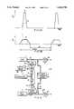
- FIG. 1is a simplified side view of an appliance of the invention, partly broken away and in installed position on a human leg, with a schematic diagram of interrelated components for operation pursuant to a presently preferred mode;
- FIG. 2Ais a graphical illustration of pressure as a function of time, for operation of a foot-pump portion of the appliance of FIG. 1;
- FIG. 2Bis a graphical illustration of pressure as a function of time, for operation of a tourniquet-cuff portion of the appliance of FIG. 1, the illustrations of FIGS. 2A and 2B being exaggerated and juxtaposed for better illustration of time-coordinated functions of the appliance;
- FIG. 3Ais a simplified graphical illustration of foot-pump pressure as a function of time for a modified mode of operation of the invention
- FIG. 3Bis a simplified graphical illustration of tourniquet-cuff pressure as a function of time, the illustrations of FIGS. 3A and 3B being juxtaposed for better illustration of coordinated functions of the modified mode;
- FIG. 4is a schematic diagram of interrelated components for operation pursuant to the modified mode of FIGS. 3A and 3B;
- FIG. 5is another schematic diagram of interrelated components for selective control as to mode of operation
- FIG. 6Ais a graphical illustration of pressure as a function of time, for foot-pump operation of FIG. 5, as in FIG. 2A;
- FIG. 6Bis a graphical illustration of pressure as a function of the time scale of FIG. 6A, for tourniquet-cuff operation of FIG. 5, as in FIG. 2B;
- FIG. 6Cis a graphical illustration of pressure as a function of the time scale of FIG. 6A, for a first-modified tourniquet-cuff operation of FIG. 5;
- FIG. 6Dis a graphical illustration of pressure as a function of the time scale of FIG. 6A, for a second-modified tourniquet-cuff operation of FIG. 5.
- the inventionis shown in application to the foot and distal calf of a human leg, wherein a foot-pump element 10 is applied to the foot, a tourniquet-calf element 11 is applied to the distal calf, and pneumatic actuating and control means 12 is connected to elements 10 and 11 for coordinated operation of the same, pursuant to a repetitive cycle, which may be within the range 15 to 60 seconds.
- the foot-pump element 10is suitably as described in said patents, so that simplified identification of parts will suffice for present purposes.
- the foot-pump element 10comprises an inflatable bag or bladder 14 shaped for engagement with the sole of the foot and in the plantar arch, namely between the ball and the heel of the foot.
- a flexible pipe 15connects bag 14 to the pneumatic supply and control means 12.
- the foot-pump element 10further comprises a suitably padded wrap 16, embracing the bag 14 and over the instep 17 of the foot, and secured as by hook and loop fastening elements 18, to complete a circumferential tie at and around the mid-tarsal joint.
- the wrap 16is shown covered by a cloth slipper 19 which covers the majority of the foot, leaving the toes exposed for the physician's inspection and reaction-testing of the involved foot.
- apparatus to be described at 12operates rapidly to inflate the bag 14, which reacts against the circumferentially tied wrap 16 to apply pumping pressure to the sole of the foot while also urging the ball and heel of the foot away from each other, thus applying upward and spreading force and transiently flattening the plantar arch, as would occur if the foot were placed on the ground (i.e., body-weight bearing) during normal ambulation, thereby stimulating venous blood flow.
- the tourniquet-cuff element 11may be a commercially available inflatable item, providing a circumferential tie around an inflatable bladder (not shown) which is preferably applied to the distal-calf region; the only exposed part of the inflatable cuff element 11 is its flexible supply pipe 20, which receives its inflation/deflation air supply from the control means 12.
- the pneumatic actuating and control means 12 of FIG. 1operates from an accumulator 21 of pressurized air, which in the case of certain hospitals may be provided by a central source of suitably pressure-regulated supply.
- self-contained means 12comprises an air pump 22, motor-driven at 23, with a relief valve 24 to determine a suitable upper limit of air pressure at accumulator 21.
- Pressurized air from the accumulatoris connected for inflation-air delivery to the foot-pump supply pipe 15, via a first solenoid-operated valve 25 of the normally closed (NC) variety, and for inflation-air delivery to the tourniquet-cuff supply pipe 20, via a second normally closed solenoid-operated valve 26.
- NCnormally closed
- Third and fourth normally closed solenoid-operated valves 27, 28are respectively connected to the foot-pump and cuff pipes 15, 20 for controlled discharge to ambient air of the respective inflatable elements 10, 11.
- Programmable control means 30will be understood to be presettable for the sequentially and suitably timed operation of the respective solenoid-operated valves, thus determining particular valve-opening events, suggested by time legends T 1 , T 3 , T 4 , T 6 which will be discussed in connection with the adjacent graphs of FIGS. 2A and 2B to the same time scale.
- the graph of FIG. 2Adisplays, with some exaggeration for clarity, a representative inflation/deflation pressure pulse for the foot-pump element 10, and the graph of FIG. 2B is a similar display for a representative inflation/deflation pressure pulse for the tourniquet-cuff element 11.
- Separately identified times T 1 , T 2 , . . . T 6 within each cycle of appliance operationserve to mark various coordinating events, as between foot-pump and tourniquet operation in the cycle, and the use of time designations T 1 to T 6 will be understood to indicate initiation of solenoid-valve actuations by means 30 in FIG. 1.
- separately adjustable variable orifices 31, 32 in the respective inflation lines to the foot-pump and cuff elements 10 and 11will be understood to provide selective control of inflation rates for these elements.
- a representative cycle of appliance operationwill commence with an actuating signal from control means 30 at time-T 1 , thus opening valve 26 and initiating inflation of cuff 11.
- the flow of inflation air from accumulator 21will preferably have been adjusted at 32 to provide a relatively slow rate of cuff inflation, so that, based on operational experience with the presssure of air from accumulator 21, an event T 2 determined by the program of means 30 will terminate the supply of accumulator air to cuff 11, by terminating the excitation of valve 26, thereby allowing valve 26 to return to its normally closed condition, with cuff 11 temporarily locked in inflated condition, at a level 33 of cuff pressure P c which will have been selected for the desired degree of local primary flow-restriction action on superficial veins, with relatively little flow-restricting action on deep veins.
- this level of cuff-inflation pressureis in the range of 30 to 100-mm Hg, being preferably in the range of 40 to 60-mm Hg; and the rate of cuff inflation is relatively slow, with cuff inflation accomplished within no less than one second.
- the solenoid valve 25is actuated to open condition, thus admitting inflation air from accumulator 21 to the foot-pump bag, pursuant to the rate of air supply selected by prior adjustment of orifice 31.
- the rising slope 34 of inflation air to a peak foot-pump pressure in excess of the transiently locked-inflation pressure 33 of cuff 11is desirably relatively rapid and in the range up to one second, being preferably in the range of 0.5 second or less. Achievement of peak foot-pump inflation pressure may be signalled by a pre-set pressure sensitive switch for terminating the actuating signal to solenoid valve 25, but in the circuitry shown in FIG.
- a peak-timing event at T 4is operative (a) to terminate the actuating signal to valve 25 and (b) to initiate actuation of solenoid valve 27, for discharge of inflation air from foot-pump element 10, thus deflating the foot-pump bag 14 as rapidly as possible and substantially immediately upon achievement of peak foot-pump pressure.
- the curve 35 of resulting relief of foot-pump pressurehas been exaggerated to enable better identification of subsequent events in the illustrative cycle of appliance operation.
- FIGS. 3A, 3B and 4illustrate a modification wherein sensed pressure thresholds determine key events in the operative sequence of cuff and foot-pump actuation in each cycle.
- Pneumatic circuitryremains substantially as already described for FIGS. 1, 2A and 2B, and therefore the same reference numbers are used, where applicable.
- Threshold sensing of a predetermined limit of cuff-inflation pressureis provided by pressure-sensitive switch means 40 in the air-supply line from solenoid valve 26 to cuff 11, and threshold sensing of a predetermined peaking limit of foot-pump pressure is provided by pressure-sensitive switch means 41 in the air-supply line from solenoid valve 25 to foot-pump 10.
- a differential-pressure switch 42is connected for differential response to instantaneous cuff and foot-pump pressures, such that switch 42 may produce an electrical output signal in line 43 to solenoid valve 27 when foot-pump pressure has been sensed to drop to or below cuff-inflation pressure.
- FIGS. 3A, 3B and 4commences with an electrical actuating signal from control means 30 to solenoid valve 26, thus opening valve 26 and admitting inflation air to cuff 11 at a relatively slow rate determined by pre-set adjustment of orifice 32. Achievement of cuff inflation to the limit 33, predetermined at 40, will activate switch 40 (a) to terminate the actuated open condition of solenoid valve 26, and (b) to actuate solenoid valve 25 to open condition. Valve 25 then admits inflation air to foot-pump 10, at a relatively fast rate determined by pre-set adjustment of orifice 31.
- FIG. 4The described operation of FIG. 4 will be seen to involve foot-pump deflation as soon as possible, once the peak-inflation level has been sensed by switch means 41. That being the case, the circuit of FIG. 4 can produce substantially the same coordination of cuff inflation and foot-pump inflation as was the case described in connection with FIG. 1. In certain situations, however, it may be desired to provide a selected relatively short period of holding the peak of foot-pump inflation pressure, before initiating the deflation process. It should be clear that such retention of foot-pump inflation in the case of FIG. 1 is achievable, merely by preselecting, at control means 30, a suitable interval between times T 3 and T 4 , for example, a selected interval of 1 to 5 seconds. In the case of FIG.
- a preselected peak-holding period of similar natureis selectively available by placing preselected timer terminals 47 (of control means 30) in series with a break in line 46, wherein such a break for series connection to terminals 47 is suggested by an "x" mark 48.
- a first level (33) of transient tourniquet pressureis applied to the leg; in the case of a diagnosed or suspected possible DVT condition or development, it is preferred that cuff 11 be applied at the distal-calf region, which for most cases will be distal to the DVT condition. And even if the DVT condition extends to the distal calf, the preferred distal-cuff application of cuff 11 is recommended.
- Transient venous-pumping pressureis then applied to the plantar region of the foot, at a relatively rapid rate and to a peaking level which exceeds that of the tourniquet action at the cuff; the cuff will thus have reduced the availability of superficial veins to accommodate pumped venous flow, so that deep veins may be targeted with enhanced effect. If a thrombolitic agent is introduced at the dorsum of the foot, as at location A in FIG.
- the venous-pumping pressuremay be relieved immediately or following a short peak-holding period, at the option of the physician who may have preferred to provide a measure of concurrent enhanced arterial flow to the leg, pursuant to the teaching of U.S. Pat. No. 4,721,101. Whatever the selected time for retention of peak venous-pump pressure, the holding time is short compared to the cycle time, so that in no case is arterial flow impaired.
- the tourniquet pressureis relieved once the venous pressure has reduced to or below the level of transiently applied tourniquet pressure. Even with a preferred relatively slow rate of tourniquet-pressure development, the period of tourniquet-pressure application is short relative to the indicated range of cycle duration, so that arterial flow remains unimpaired if not enhanced.
- the inventionis also seen to have further application for the bed-ridden patient for whom the orthopedic surgeon may have ordered a foot to be suspended in elevated relation with respect to the heart.
- the plantar veinswill necessarily be above heart elevation, thus inviting slow gravitational drainage of plantar veins and preventing such plantar-vein accumulation of blood as could be the subject of artificial foot-pump actuation.
- the cuff 11particularly when located at the distal calf and inflated to the already indicated pressure range, and for the relatively long period up to 10 seconds, or for a period of at least 10 seconds prior to foot-pump actuation, will permit a desirable volume of plantar-vein accumulation by the time the foot-pump is activated at the rate and to the peak-pressure range already discussed.
- the cuff 11should also be deflated, until need for renewed cuff inflation for the next cycle of coordinated cuff and foot-pump actuation.
- FIG. 5provides further schematic illustration of appliance components capable of various selected operations of cuff 11 in timed relation to foot-pump (14) operation, wherein programmable control means 130 is seen to determine the sequencing and/or interlacing of events governed by four solenoid valves, 125, 126, 127, 128, which may be of normally closed variety, as suggested by the symbol NC, it being understood that in FIG. 5 such flow-control devices as suitably adjusted variable orifices in the respective lines for these solenoid valves have been omitted, for simplification of the drawing. As shown in FIG.
- separate regulator valves 124, 124'operate from a single pressure-fluid source and are selectively adjustable to determine, respectively, a first and relatively low regulated pressure available for cuff inflation from a first accumulator 121, and a second and relatively elevated regulated pressure available for foot-pump inflation from a second accumulator 121'.
- valve (125) openingwill be understood to effect relatively rapid inflation of foot-pump 14 via a relatively fast rise 134 to a peak of pressure (P p ), followed by a relatively gentle relaxation (135) from peak inflation pressure upon actuation of a venting solenoid 127 (with valve 125 in its NC condition); alternatively, with delayed actuation of the venting solenoid 127 (to the delayed extent ⁇ ), peak inflation pressure can be retained, and the gentle relaxation profile 135' will be correspondingly delayed.
- the arterial-flow enhancement properties of delayed retention of peak foot-pump inflation pressureare discussed in greater detail in U.S. Pat. No. Re. 32,940.
- a concurrent program of cuff-11 inflation and relaxationis controlled by means 130 to supply cuff-inflation pressure fluid from accumulator 121 upon actuation of valve 126, the cuff inflation being shown in FIG. 6B to be retained until relaxation of foot-pump pressure reduces at least to the level of cuff-inflation pressure.
- the designation PC1is adopted in FIG. 6B, for consideration alongside the foot-pump pressure profile of FIG. 6A, to illustrate use of the control apparatus of FIG. 5 to determine the DVT-reducing mode described in connection with FIGS. 1, 2A and 2B.
- FIG. 5Further uses of the control apparatus of FIG. 5 are illustrated by the respective cuff-pressure profiles PC2 and PC3 of FIGS. 6C and 6D, which are particularly helpful in aid of a patient whose leg must be supported in an elevated state that necessarily places his foot, the foot-pump 14 and the cuff 11 above the elevation of his heart, as he lies in bed.
- FIG. 6Cwhich presents the cuff-inflation pressure profile (PC2) to the same time scale as the foot-pump inflation profile (P p ) of FIG. 6A
- the inflation of cuff 11occurs for a substantial fraction (e.g., one half) of the full cycle, as an event serving to "prime” the plantar veins immediately prior to foot-pump inflation, so that foot-pump action may have a fuller accumulation of blood in readiness for pumped venous return.
- the primingis fully completed at the instant of commencing foot-pump inflation, and in FIG.
- the profile (PC3) of cuff pressure inflationis seen to lap the foot-pump inflation profile (P p ) at least during the rise time of foot-pump inflation.
- the result of pumped venous-return effectivenessis substantially the same for FIG. 6C and for FIG. 6D, but the venting of cuff pressure is preferred to be substantially complete, as of the initiation of foot-pump inflation.
- the peak of foot-pump pressure needed for the DVT treatment situationdoes not call for such elevated magnitudes as for a situation where DVT is not a problem.
- the DVT treatment wherein a thrombolizing agent is injected at the dorsum of the footis relying upon the cuff to apply tourniquet action on the superficial veins so that deep veins can be more efficiently treated with the thrombolizing agent, in which case a cuff pressure in the order of 50-mm Hg and a peak foot-pump pressure in the range 100 to 200-mm Hg may be sufficient, and with a more gentle rising slope (e.g., to peak foot-pump pressure within 2 seconds or less).
- the priming cuff pressuremay be substantially the same as for DVT treatment, but with preferably a pressure peak of foot-pump inflation of at least 200-mm Hg.
Landscapes
- Health & Medical Sciences (AREA)
- Epidemiology (AREA)
- Pain & Pain Management (AREA)
- Physical Education & Sports Medicine (AREA)
- Rehabilitation Therapy (AREA)
- Life Sciences & Earth Sciences (AREA)
- Animal Behavior & Ethology (AREA)
- General Health & Medical Sciences (AREA)
- Public Health (AREA)
- Veterinary Medicine (AREA)
- Surgical Instruments (AREA)
Abstract
Description
Claims (25)
Priority Applications (1)
| Application Number | Priority Date | Filing Date | Title |
|---|---|---|---|
| US08/414,753US5584798A (en) | 1992-11-23 | 1995-03-31 | Medical inflatable cuff appliance |
Applications Claiming Priority (3)
| Application Number | Priority Date | Filing Date | Title |
|---|---|---|---|
| US98058092A | 1992-11-23 | 1992-11-23 | |
| US15632093A | 1993-11-22 | 1993-11-22 | |
| US08/414,753US5584798A (en) | 1992-11-23 | 1995-03-31 | Medical inflatable cuff appliance |
Related Parent Applications (1)
| Application Number | Title | Priority Date | Filing Date |
|---|---|---|---|
| US15632093AContinuation | 1992-11-23 | 1993-11-22 |
Publications (1)
| Publication Number | Publication Date |
|---|---|
| US5584798Atrue US5584798A (en) | 1996-12-17 |
Family
ID=26853063
Family Applications (1)
| Application Number | Title | Priority Date | Filing Date |
|---|---|---|---|
| US08/414,753Expired - LifetimeUS5584798A (en) | 1992-11-23 | 1995-03-31 | Medical inflatable cuff appliance |
Country Status (1)
| Country | Link |
|---|---|
| US (1) | US5584798A (en) |
Cited By (86)
| Publication number | Priority date | Publication date | Assignee | Title |
|---|---|---|---|---|
| US5669872A (en)* | 1992-11-23 | 1997-09-23 | Novamedix Limited | Method for focused delivery of venous flow for artificial impluse compression of an anatomical foot pump |
| WO1998031278A3 (en)* | 1996-09-30 | 1998-11-12 | Kci New Technologies Inc | Remote controllable medical pumping apparatus |
| US6171270B1 (en)* | 1999-01-19 | 2001-01-09 | Jun-Shyan Gau | Apparatus for distributed air pressure massage |
| US6290662B1 (en)* | 1999-05-28 | 2001-09-18 | John K. Morris | Portable, self-contained apparatus for deep vein thrombosis (DVT) prophylaxis |
| US6358219B1 (en)* | 1996-09-06 | 2002-03-19 | Aci Medical | System and method of improving vascular blood flow |
| WO2001093747A3 (en)* | 2000-06-07 | 2002-07-18 | Aircast Inc | Method and apparatus for facilitating the healing of bone fractures |
| US6544202B2 (en)* | 1998-08-12 | 2003-04-08 | Mcewen James Allen | Apparatus and method for applying an adaptable pressure waveform to a limb |
| US20030069528A1 (en)* | 2001-09-21 | 2003-04-10 | Herz Frederick Stephan Michael | Prevention and treatment of deep venous thrombosis |
| US20030167057A1 (en)* | 2000-06-07 | 2003-09-04 | Aircast, Inc. | Method and apparatus for facilitating the healing of bone fractures |
| US20030176822A1 (en)* | 2002-03-12 | 2003-09-18 | Morgenlander Joel C. | Method of treating restless leg syndrome |
| US6648840B2 (en) | 1996-08-02 | 2003-11-18 | Salton, Inc. | Microcontroller based massage system |
| US20040092853A1 (en)* | 2001-03-13 | 2004-05-13 | Michael Degun | Orthopaedic splint |
| US20050143682A1 (en)* | 2003-12-31 | 2005-06-30 | Novamedix Distribution Limited | Garment for use in pump therapy for enhancing venous and arterial blood flow |
| USD513324S1 (en) | 2003-12-20 | 2005-12-27 | Novamedix Distribution Limited | Impulse therapy garment |
| USD517695S1 (en) | 2004-02-23 | 2006-03-21 | Tyco Healthcare Group Ip | Compression sleeve |
| US20060064800A1 (en)* | 2004-09-27 | 2006-03-30 | Freund Robert M | Decubitus ulcer prevention and treatment |
| US7044924B1 (en) | 2000-06-02 | 2006-05-16 | Midtown Technology | Massage device |
| USD523147S1 (en) | 2004-02-23 | 2006-06-13 | Tyco Healthcare Group Lp | Compression sleeve |
| US20070010770A1 (en)* | 2005-07-07 | 2007-01-11 | Gildersleeve Richard E | Pneumatic liner with pressure relief valve and method of supporting an extremity with a pneumatic liner with pressure relief valve |
| US20070088239A1 (en)* | 2000-06-02 | 2007-04-19 | Midtown Technology Ltd. | Inflatable massage garment |
| US20070135743A1 (en)* | 2005-12-12 | 2007-06-14 | Ann Meyer | Compression apparatus |
| US7282038B2 (en) | 2004-02-23 | 2007-10-16 | Tyco Healthcare Group Lp | Compression apparatus |
| US20070260164A1 (en)* | 2006-03-22 | 2007-11-08 | Darco International, Inc. | Device and method for treating foot with adustable bladder |
| US20070282230A1 (en)* | 2005-12-15 | 2007-12-06 | Djo, Llc | Systems and methods for applying reversed sequence pressure to control edema flow |
| USD569985S1 (en) | 2007-06-08 | 2008-05-27 | Tyco Healthcare Group Lp | Foot cuff for therapeutic compression of a foot |
| USD579116S1 (en) | 2007-07-27 | 2008-10-21 | Tyco Healthcare Group Lp | Foot cuff with tapered, blunt end |
| US20090131935A1 (en)* | 2007-11-15 | 2009-05-21 | Yeager David A | Method of preparing a patient's leg in need of treatment, for ambulation |
| US7641623B2 (en) | 2003-04-11 | 2010-01-05 | Hill-Rom Services, Inc. | System for compression therapy with patient support |
| USD608006S1 (en) | 2007-04-09 | 2010-01-12 | Tyco Healthcare Group Lp | Compression device |
| US20100010398A1 (en)* | 2008-07-08 | 2010-01-14 | Leap Frogg, Llc | Foot compression system |
| US20100042028A1 (en)* | 2008-08-14 | 2010-02-18 | Albahealth, LLC | Foot wrap with inflatable bladder |
| USD618358S1 (en) | 2007-04-09 | 2010-06-22 | Tyco Healthcare Group Lp | Opening in an inflatable member for a pneumatic compression device |
| US20100200627A1 (en)* | 2009-01-15 | 2010-08-12 | Marc Shen | Ankle Tourniquet Holster |
| US7871387B2 (en) | 2004-02-23 | 2011-01-18 | Tyco Healthcare Group Lp | Compression sleeve convertible in length |
| US20110214315A1 (en)* | 2010-03-05 | 2011-09-08 | Leap Frogg, Llc | Therapy shoe |
| US8016779B2 (en) | 2007-04-09 | 2011-09-13 | Tyco Healthcare Group Lp | Compression device having cooling capability |
| US8021388B2 (en) | 2007-04-09 | 2011-09-20 | Tyco Healthcare Group Lp | Compression device with improved moisture evaporation |
| US8029450B2 (en) | 2007-04-09 | 2011-10-04 | Tyco Healthcare Group Lp | Breathable compression device |
| US8029451B2 (en) | 2005-12-12 | 2011-10-04 | Tyco Healthcare Group Lp | Compression sleeve having air conduits |
| US8034007B2 (en) | 2007-04-09 | 2011-10-11 | Tyco Healthcare Group Lp | Compression device with structural support features |
| US8070699B2 (en) | 2007-04-09 | 2011-12-06 | Tyco Healthcare Group Lp | Method of making compression sleeve with structural support features |
| US8109892B2 (en) | 2007-04-09 | 2012-02-07 | Tyco Healthcare Group Lp | Methods of making compression device with improved evaporation |
| US8114117B2 (en) | 2008-09-30 | 2012-02-14 | Tyco Healthcare Group Lp | Compression device with wear area |
| US8128584B2 (en) | 2007-04-09 | 2012-03-06 | Tyco Healthcare Group Lp | Compression device with S-shaped bladder |
| US8162861B2 (en) | 2007-04-09 | 2012-04-24 | Tyco Healthcare Group Lp | Compression device with strategic weld construction |
| US8235923B2 (en) | 2008-09-30 | 2012-08-07 | Tyco Healthcare Group Lp | Compression device with removable portion |
| US20120283607A1 (en)* | 2010-09-23 | 2012-11-08 | Batra Munish K | Heated Compression Therapy System and Method |
| US8460224B2 (en) | 2010-04-09 | 2013-06-11 | Michael L. Wilford | Therapeutic compression apparatus |
| US8506508B2 (en) | 2007-04-09 | 2013-08-13 | Covidien Lp | Compression device having weld seam moisture transfer |
| US8539647B2 (en) | 2005-07-26 | 2013-09-24 | Covidien Ag | Limited durability fastening for a garment |
| US8636678B2 (en) | 2008-07-01 | 2014-01-28 | Covidien Lp | Inflatable member for compression foot cuff |
| US8652079B2 (en) | 2010-04-02 | 2014-02-18 | Covidien Lp | Compression garment having an extension |
| US8801643B2 (en) | 2010-02-12 | 2014-08-12 | Covidien Lp | Compression garment assembly |
| US8979915B2 (en) | 2010-04-19 | 2015-03-17 | Pulsar Scientific, LLC | Separable system for applying compression and thermal treatment |
| US9114053B2 (en) | 2007-05-08 | 2015-08-25 | Wright Therapy Products, Inc. | Pneumatic compression therapy system and methods of using same |
| US9132057B2 (en) | 2012-07-09 | 2015-09-15 | Michael L. Wilford | Therapeutic wrap |
| US9205021B2 (en) | 2012-06-18 | 2015-12-08 | Covidien Lp | Compression system with vent cooling feature |
| US9259343B2 (en) | 2012-07-06 | 2016-02-16 | Newman Technologies LLC | Device for mitigating plantar fasciitis |
| US9295605B2 (en) | 2013-12-02 | 2016-03-29 | Wright Therapy Products, Inc. | Methods and systems for auto-calibration of a pneumatic compression device |
| US9433532B2 (en) | 2008-09-30 | 2016-09-06 | Covidien Lp | Tubeless compression device |
| US9439828B2 (en) | 2008-07-08 | 2016-09-13 | Avex, L.L.C. | Foot compression system |
| US9510994B2 (en) | 2014-02-07 | 2016-12-06 | Michael L Wilford | Therapeutic wrap with pattern zone |
| US9737238B2 (en) | 2012-08-18 | 2017-08-22 | Wright Therapy Products, Inc. | Methods for determining the size of body parts as part of compression therapy procedures |
| US9737454B2 (en) | 2012-03-02 | 2017-08-22 | Hill-Rom Services, Inc. | Sequential compression therapy compliance monitoring systems and methods |
| US9757302B2 (en) | 2011-08-12 | 2017-09-12 | Avex, Llc | Foot compression and electrical stimulation system |
| US9872812B2 (en) | 2012-09-28 | 2018-01-23 | Kpr U.S., Llc | Residual pressure control in a compression device |
| US9889063B2 (en) | 2012-06-11 | 2018-02-13 | Wright Therapy Products, Inc. | Methods and systems for determining use compliance of a compression therapy device |
| US10195102B2 (en) | 2012-03-12 | 2019-02-05 | Tactile Systems Technology, Inc. | Compression therapy device with multiple simultaneously active chambers |
| US10292894B2 (en) | 2014-02-11 | 2019-05-21 | Tactile Systems Technology, Inc. | Compression therapy device and compression therapy protocols |
| US10369075B2 (en) | 2015-03-03 | 2019-08-06 | Avex, Llc | Insole foot compression system and methods |
| US10470967B2 (en) | 2014-01-20 | 2019-11-12 | Tactile Systems Technology, Inc. | Bespoke compression therapy device |
| US10507131B2 (en)* | 1998-06-08 | 2019-12-17 | Thermotek, Inc. | Method and system for thermal and compression therapy relative to the prevention of deep vein thrombosis |
| US10507158B2 (en) | 2016-02-18 | 2019-12-17 | Hill-Rom Services, Inc. | Patient support apparatus having an integrated limb compression device |
| US10751221B2 (en) | 2010-09-14 | 2020-08-25 | Kpr U.S., Llc | Compression sleeve with improved position retention |
| US10799415B2 (en) | 2011-12-02 | 2020-10-13 | Avex, Llc | Spring-driven foot compression system |
| US10893998B2 (en) | 2018-10-10 | 2021-01-19 | Inova Labs Inc. | Compression apparatus and systems for circulatory disorders |
| AU2019204163B2 (en)* | 2013-01-29 | 2021-04-01 | Mc Health Tech S.L. | New diagnostic and treatment methods |
| US20210244604A1 (en)* | 2010-02-08 | 2021-08-12 | Gnotrix, Llc | Treatment devices and methods |
| US20220096308A1 (en)* | 2019-01-29 | 2022-03-31 | Leonardo Osti | Plantar pressing device and relative controlled mobilization apparatus |
| US11638675B2 (en) | 2018-11-07 | 2023-05-02 | Zenith Technical Innovations, Llc | System and method for heat or cold therapy and compression therapy |
| US11839588B2 (en)* | 2014-07-17 | 2023-12-12 | Gnotrix, Llc | Systems and methods for multiple pulses for treatment of vascular conditions |
| US11850183B2 (en) | 2019-08-20 | 2023-12-26 | Michael L. Wilford | Head wrap |
| US11857491B2 (en) | 2019-03-13 | 2024-01-02 | Breg, Inc. | Integrated cold therapy-compression therapy assembly and associated treatment protocols |
| USD1089667S1 (en) | 2023-11-30 | 2025-08-19 | Michael L. Wilford | Lumbar wrap |
| USD1089666S1 (en) | 2023-11-30 | 2025-08-19 | Michael L. Wilford | Cervical wrap |
| USD1089665S1 (en) | 2023-11-30 | 2025-08-19 | Michael L. Wilford | Shoulder wrap |
Citations (40)
| Publication number | Priority date | Publication date | Assignee | Title |
|---|---|---|---|---|
| US2694395A (en)* | 1951-05-10 | 1954-11-16 | William J Brown | Pneumatic pressure garment |
| US3525333A (en)* | 1967-09-04 | 1970-08-25 | Mencacci Samuel | Device to stimulate peristaltic movements |
| US3811431A (en)* | 1973-01-17 | 1974-05-21 | M Apstein | Programmed venous assist pump |
| US3824992A (en)* | 1973-03-16 | 1974-07-23 | Clinical Technology Inc | Pressure garment |
| US3826249A (en)* | 1973-01-30 | 1974-07-30 | A Lee | Leg constricting apparatus |
| US3865103A (en)* | 1973-11-08 | 1975-02-11 | Raymond Lee Organization Inc | Blood circulating device |
| US3865102A (en)* | 1973-06-13 | 1975-02-11 | Hemodyne Inc | External cardiac assist apparatus |
| US3892229A (en)* | 1973-12-06 | 1975-07-01 | Duane F Taylor | Apparatus for augmenting venous blood flow |
| US3908642A (en)* | 1973-10-29 | 1975-09-30 | Pred Vinmont | Means for aerating and applying air pulsations within casts |
| US3920006A (en)* | 1974-01-02 | 1975-11-18 | Roy Lapidus Inc | Inflatable device for healing of tissue |
| DE2433794A1 (en)* | 1974-07-13 | 1976-01-29 | Josef Dr Med Pflug | Healing device for body wounds - has elastic material held against wound and pulsated by fluid in pipe |
| US3976056A (en)* | 1974-05-18 | 1976-08-24 | Peter Nelson Brawn | Intermittent pressure pneumatic stocking |
| US3982531A (en)* | 1975-04-30 | 1976-09-28 | Thiokol Corporation | Inflation device for a pneumatic orthosis |
| US3993053A (en)* | 1974-08-05 | 1976-11-23 | Murray Grossan | Pulsating massage system |
| US4030488A (en)* | 1975-10-28 | 1977-06-21 | The Kendall Company | Intermittent compression device |
| US4044759A (en)* | 1976-02-11 | 1977-08-30 | Bahman Ghayouran | Auto-transfusion torniquet appliance and method of utilizing the same to control flow of blood through a blood vessel |
| US4054129A (en)* | 1976-03-29 | 1977-10-18 | Alba-Waldensian, Inc. | System for applying pulsating pressure to the body |
| US4077402A (en)* | 1976-06-25 | 1978-03-07 | Benjamin Jr J Malvern | Apparatus for promoting blood circulation |
| US4091804A (en)* | 1976-12-10 | 1978-05-30 | The Kendall Company | Compression sleeve |
| DE2716137A1 (en)* | 1976-12-27 | 1978-07-06 | Thomas Peter Muchisky | MASSAGE DEVICE |
| US4153050A (en)* | 1977-07-29 | 1979-05-08 | Alba-Waldensian, Incorporated | Pulsatile stocking and bladder therefor |
| US4186732A (en)* | 1977-12-05 | 1980-02-05 | American Hospital Supply Corporation | Method and apparatus for pulsing a blood flow stimulator |
| US4198961A (en)* | 1979-01-12 | 1980-04-22 | The Kendall Company | Compression device with sleeve retained conduits |
| US4202325A (en)* | 1979-01-12 | 1980-05-13 | The Kendall Company | Compression device with improved fastening sleeve |
| US4206751A (en)* | 1978-03-31 | 1980-06-10 | Minnesota Mining And Manufacturing Company | Intermittent compression device |
| US4207876A (en)* | 1979-01-12 | 1980-06-17 | The Kendall Company | Compression device with ventilated sleeve |
| US4231355A (en)* | 1977-09-29 | 1980-11-04 | Katsumasa Hara | Device for air-massage |
| US4269175A (en)* | 1977-06-06 | 1981-05-26 | Dillon Richard S | Promoting circulation of blood |
| US4311135A (en)* | 1979-10-29 | 1982-01-19 | Brueckner Gerald G | Apparatus to assist leg venous and skin circulation |
| US4370975A (en)* | 1980-08-27 | 1983-02-01 | Wright Edward S | Apparatus promoting flow of a body fluid in a human limb |
| US4372297A (en)* | 1980-11-28 | 1983-02-08 | The Kendall Company | Compression device |
| US4374518A (en)* | 1980-10-09 | 1983-02-22 | Raul Villanueva | Electronic device for pneumomassage to reduce lymphedema |
| US4402312A (en)* | 1981-08-21 | 1983-09-06 | The Kendall Company | Compression device |
| US4418690A (en)* | 1981-08-03 | 1983-12-06 | Jobst Institute, Inc. | Apparatus and method for applying a dynamic pressure wave to an extremity |
| US4453538A (en)* | 1977-04-07 | 1984-06-12 | Whitney John K | Medical apparatus |
| US4696289A (en)* | 1983-06-22 | 1987-09-29 | Electro-Biology, Inc. | Method of promoting venous pump action |
| US4721101A (en)* | 1984-06-18 | 1988-01-26 | Electro-Biology, Inc. | Medical appliance |
| USRE32940E (en)* | 1983-06-22 | 1989-06-06 | Electro-Biology, Inc. | Medical appliance |
| US4841956A (en)* | 1985-10-15 | 1989-06-27 | Electro-Biology, Inc. | Apparatus for inducing venous-return flow from the leg |
| US5186163A (en)* | 1991-11-25 | 1993-02-16 | The Kendall Company | Compression device |
- 1995
- 1995-03-31USUS08/414,753patent/US5584798A/ennot_activeExpired - Lifetime
Patent Citations (44)
| Publication number | Priority date | Publication date | Assignee | Title |
|---|---|---|---|---|
| US2694395A (en)* | 1951-05-10 | 1954-11-16 | William J Brown | Pneumatic pressure garment |
| US3525333A (en)* | 1967-09-04 | 1970-08-25 | Mencacci Samuel | Device to stimulate peristaltic movements |
| US3811431A (en)* | 1973-01-17 | 1974-05-21 | M Apstein | Programmed venous assist pump |
| US3826249A (en)* | 1973-01-30 | 1974-07-30 | A Lee | Leg constricting apparatus |
| US3824992A (en)* | 1973-03-16 | 1974-07-23 | Clinical Technology Inc | Pressure garment |
| US3865102A (en)* | 1973-06-13 | 1975-02-11 | Hemodyne Inc | External cardiac assist apparatus |
| US3908642A (en)* | 1973-10-29 | 1975-09-30 | Pred Vinmont | Means for aerating and applying air pulsations within casts |
| US3865103A (en)* | 1973-11-08 | 1975-02-11 | Raymond Lee Organization Inc | Blood circulating device |
| US3892229A (en)* | 1973-12-06 | 1975-07-01 | Duane F Taylor | Apparatus for augmenting venous blood flow |
| US3920006A (en)* | 1974-01-02 | 1975-11-18 | Roy Lapidus Inc | Inflatable device for healing of tissue |
| US3976056A (en)* | 1974-05-18 | 1976-08-24 | Peter Nelson Brawn | Intermittent pressure pneumatic stocking |
| DE2433794A1 (en)* | 1974-07-13 | 1976-01-29 | Josef Dr Med Pflug | Healing device for body wounds - has elastic material held against wound and pulsated by fluid in pipe |
| US3993053A (en)* | 1974-08-05 | 1976-11-23 | Murray Grossan | Pulsating massage system |
| US3982531A (en)* | 1975-04-30 | 1976-09-28 | Thiokol Corporation | Inflation device for a pneumatic orthosis |
| US4030488A (en)* | 1975-10-28 | 1977-06-21 | The Kendall Company | Intermittent compression device |
| US4044759A (en)* | 1976-02-11 | 1977-08-30 | Bahman Ghayouran | Auto-transfusion torniquet appliance and method of utilizing the same to control flow of blood through a blood vessel |
| US4054129A (en)* | 1976-03-29 | 1977-10-18 | Alba-Waldensian, Inc. | System for applying pulsating pressure to the body |
| US4077402A (en)* | 1976-06-25 | 1978-03-07 | Benjamin Jr J Malvern | Apparatus for promoting blood circulation |
| US4091804A (en)* | 1976-12-10 | 1978-05-30 | The Kendall Company | Compression sleeve |
| DE2716137A1 (en)* | 1976-12-27 | 1978-07-06 | Thomas Peter Muchisky | MASSAGE DEVICE |
| US4453538A (en)* | 1977-04-07 | 1984-06-12 | Whitney John K | Medical apparatus |
| US4269175A (en)* | 1977-06-06 | 1981-05-26 | Dillon Richard S | Promoting circulation of blood |
| US4153050A (en)* | 1977-07-29 | 1979-05-08 | Alba-Waldensian, Incorporated | Pulsatile stocking and bladder therefor |
| US4231355A (en)* | 1977-09-29 | 1980-11-04 | Katsumasa Hara | Device for air-massage |
| US4186732A (en)* | 1977-12-05 | 1980-02-05 | American Hospital Supply Corporation | Method and apparatus for pulsing a blood flow stimulator |
| US4206751A (en)* | 1978-03-31 | 1980-06-10 | Minnesota Mining And Manufacturing Company | Intermittent compression device |
| US4198961A (en)* | 1979-01-12 | 1980-04-22 | The Kendall Company | Compression device with sleeve retained conduits |
| US4207876A (en)* | 1979-01-12 | 1980-06-17 | The Kendall Company | Compression device with ventilated sleeve |
| US4202325A (en)* | 1979-01-12 | 1980-05-13 | The Kendall Company | Compression device with improved fastening sleeve |
| US4311135A (en)* | 1979-10-29 | 1982-01-19 | Brueckner Gerald G | Apparatus to assist leg venous and skin circulation |
| US4370975A (en)* | 1980-08-27 | 1983-02-01 | Wright Edward S | Apparatus promoting flow of a body fluid in a human limb |
| US4374518A (en)* | 1980-10-09 | 1983-02-22 | Raul Villanueva | Electronic device for pneumomassage to reduce lymphedema |
| US4372297A (en)* | 1980-11-28 | 1983-02-08 | The Kendall Company | Compression device |
| US4418690A (en)* | 1981-08-03 | 1983-12-06 | Jobst Institute, Inc. | Apparatus and method for applying a dynamic pressure wave to an extremity |
| US4402312A (en)* | 1981-08-21 | 1983-09-06 | The Kendall Company | Compression device |
| US4696289A (en)* | 1983-06-22 | 1987-09-29 | Electro-Biology, Inc. | Method of promoting venous pump action |
| USRE32940E (en)* | 1983-06-22 | 1989-06-06 | Electro-Biology, Inc. | Medical appliance |
| US4696289B1 (en)* | 1983-06-22 | 1999-10-12 | Novamedix Ltd | Method of stimulating the venous-pump of the foot and for enchancement of arterial flow to the foot |
| USRE32940F1 (en)* | 1983-06-22 | 2002-06-11 | Novamedix Distrib Ltd | Method for stimulating the venous-pump mechanism of the foot |
| US4696289C1 (en)* | 1983-06-22 | 2002-09-03 | Novamedix Distrib Ltd | Method of stimulating the venous-pump mechanism of the foot and for enhancement of arterial flow to the foot |
| US4721101A (en)* | 1984-06-18 | 1988-01-26 | Electro-Biology, Inc. | Medical appliance |
| US4721101C1 (en)* | 1984-06-18 | 2002-06-18 | Novamedix Distrib Ltd | Medical appliance for artificial actuation of the venous-pump mechanism in a human foot and for enhancement of arterial flow |
| US4841956A (en)* | 1985-10-15 | 1989-06-27 | Electro-Biology, Inc. | Apparatus for inducing venous-return flow from the leg |
| US5186163A (en)* | 1991-11-25 | 1993-02-16 | The Kendall Company | Compression device |
Cited By (133)
| Publication number | Priority date | Publication date | Assignee | Title |
|---|---|---|---|---|
| US5669872A (en)* | 1992-11-23 | 1997-09-23 | Novamedix Limited | Method for focused delivery of venous flow for artificial impluse compression of an anatomical foot pump |
| US6648840B2 (en) | 1996-08-02 | 2003-11-18 | Salton, Inc. | Microcontroller based massage system |
| US6358219B1 (en)* | 1996-09-06 | 2002-03-19 | Aci Medical | System and method of improving vascular blood flow |
| WO1998031278A3 (en)* | 1996-09-30 | 1998-11-12 | Kci New Technologies Inc | Remote controllable medical pumping apparatus |
| US6387065B1 (en)* | 1996-09-30 | 2002-05-14 | Kinetic Concepts, Inc. | Remote controllable medical pumping apparatus |
| US10507131B2 (en)* | 1998-06-08 | 2019-12-17 | Thermotek, Inc. | Method and system for thermal and compression therapy relative to the prevention of deep vein thrombosis |
| US6544202B2 (en)* | 1998-08-12 | 2003-04-08 | Mcewen James Allen | Apparatus and method for applying an adaptable pressure waveform to a limb |
| US6171270B1 (en)* | 1999-01-19 | 2001-01-09 | Jun-Shyan Gau | Apparatus for distributed air pressure massage |
| US6290662B1 (en)* | 1999-05-28 | 2001-09-18 | John K. Morris | Portable, self-contained apparatus for deep vein thrombosis (DVT) prophylaxis |
| US7044924B1 (en) | 2000-06-02 | 2006-05-16 | Midtown Technology | Massage device |
| US20070088239A1 (en)* | 2000-06-02 | 2007-04-19 | Midtown Technology Ltd. | Inflatable massage garment |
| US7771376B2 (en) | 2000-06-02 | 2010-08-10 | Midtown Technology Ltd. | Inflatable massage garment |
| US20030167057A1 (en)* | 2000-06-07 | 2003-09-04 | Aircast, Inc. | Method and apparatus for facilitating the healing of bone fractures |
| US6551317B2 (en) | 2000-06-07 | 2003-04-22 | Aircast, Inc. | Method and apparatus for facilitating the healing of bone fractures |
| US7637923B2 (en) | 2000-06-07 | 2009-12-29 | Djo, Llc | Method and apparatus for facilitating the healing of bone fractures |
| US7001384B2 (en) | 2000-06-07 | 2006-02-21 | Aircast Llc | Method and apparatus for facilitating the healing of bone fractures |
| WO2001093747A3 (en)* | 2000-06-07 | 2002-07-18 | Aircast Inc | Method and apparatus for facilitating the healing of bone fractures |
| US20060111740A1 (en)* | 2000-06-07 | 2006-05-25 | Ai Asset Acquisition Company Llc | Method and apparatus for facilitating the healing of bone fractures |
| US20040092853A1 (en)* | 2001-03-13 | 2004-05-13 | Michael Degun | Orthopaedic splint |
| US8936588B2 (en)* | 2001-09-21 | 2015-01-20 | Fred Herz Patents, LLC | Device and method for prevention and treatment of deep venous thrombosis |
| US20030069528A1 (en)* | 2001-09-21 | 2003-04-10 | Herz Frederick Stephan Michael | Prevention and treatment of deep venous thrombosis |
| US9433553B2 (en) | 2001-09-21 | 2016-09-06 | Fred Herz Patents, LLC | Device and method for prevention and treatment of deep venous thrombosis |
| US20030176822A1 (en)* | 2002-03-12 | 2003-09-18 | Morgenlander Joel C. | Method of treating restless leg syndrome |
| US20050026912A1 (en)* | 2002-03-12 | 2005-02-03 | Morgenlander Joel C. | Method of treating restless leg syndrome |
| US7641623B2 (en) | 2003-04-11 | 2010-01-05 | Hill-Rom Services, Inc. | System for compression therapy with patient support |
| US9220655B2 (en) | 2003-04-11 | 2015-12-29 | Hill-Rom Services, Inc. | System for compression therapy |
| USD513324S1 (en) | 2003-12-20 | 2005-12-27 | Novamedix Distribution Limited | Impulse therapy garment |
| US7452340B2 (en) | 2003-12-31 | 2008-11-18 | Novamedix Distribution Limited | Garment for use in pump therapy for enhancing venous and arterial blood flow |
| US7677605B2 (en) | 2003-12-31 | 2010-03-16 | Novamedix Distribution Limited | Hose-clamp system for an inflatable medical device |
| US20050143682A1 (en)* | 2003-12-31 | 2005-06-30 | Novamedix Distribution Limited | Garment for use in pump therapy for enhancing venous and arterial blood flow |
| US20090121480A1 (en)* | 2003-12-31 | 2009-05-14 | Novamedix Distribution Limited | Garment for use in pump therapy for enhancing venous and arterial blood flow |
| USD517695S1 (en) | 2004-02-23 | 2006-03-21 | Tyco Healthcare Group Ip | Compression sleeve |
| USD523147S1 (en) | 2004-02-23 | 2006-06-13 | Tyco Healthcare Group Lp | Compression sleeve |
| US7282038B2 (en) | 2004-02-23 | 2007-10-16 | Tyco Healthcare Group Lp | Compression apparatus |
| US7871387B2 (en) | 2004-02-23 | 2011-01-18 | Tyco Healthcare Group Lp | Compression sleeve convertible in length |
| US7823219B2 (en) | 2004-09-27 | 2010-11-02 | Angiosome, Inc. | Decubitus ulcer prevention and treatment |
| US20060064800A1 (en)* | 2004-09-27 | 2006-03-30 | Freund Robert M | Decubitus ulcer prevention and treatment |
| US20100198122A1 (en)* | 2004-09-27 | 2010-08-05 | Angiosome, Inc. | Methods and apparatus for decubitus ulcer prevention and treatment |
| US20070010770A1 (en)* | 2005-07-07 | 2007-01-11 | Gildersleeve Richard E | Pneumatic liner with pressure relief valve and method of supporting an extremity with a pneumatic liner with pressure relief valve |
| US9364037B2 (en) | 2005-07-26 | 2016-06-14 | Covidien Ag | Limited durability fastening for a garment |
| US8539647B2 (en) | 2005-07-26 | 2013-09-24 | Covidien Ag | Limited durability fastening for a garment |
| US8079970B2 (en) | 2005-12-12 | 2011-12-20 | Tyco Healthcare Group Lp | Compression sleeve having air conduits formed by a textured surface |
| US20070135743A1 (en)* | 2005-12-12 | 2007-06-14 | Ann Meyer | Compression apparatus |
| US8029451B2 (en) | 2005-12-12 | 2011-10-04 | Tyco Healthcare Group Lp | Compression sleeve having air conduits |
| US7931606B2 (en) | 2005-12-12 | 2011-04-26 | Tyco Healthcare Group Lp | Compression apparatus |
| US20070282230A1 (en)* | 2005-12-15 | 2007-12-06 | Djo, Llc | Systems and methods for applying reversed sequence pressure to control edema flow |
| US7833184B2 (en)* | 2006-03-22 | 2010-11-16 | Darco International, Inc. | Device and method for treating foot with adustable bladder |
| US20070260164A1 (en)* | 2006-03-22 | 2007-11-08 | Darco International, Inc. | Device and method for treating foot with adustable bladder |
| US8622942B2 (en) | 2007-04-09 | 2014-01-07 | Covidien Lp | Method of making compression sleeve with structural support features |
| USD618358S1 (en) | 2007-04-09 | 2010-06-22 | Tyco Healthcare Group Lp | Opening in an inflatable member for a pneumatic compression device |
| US9387146B2 (en) | 2007-04-09 | 2016-07-12 | Covidien Lp | Compression device having weld seam moisture transfer |
| US8109892B2 (en) | 2007-04-09 | 2012-02-07 | Tyco Healthcare Group Lp | Methods of making compression device with improved evaporation |
| US8016779B2 (en) | 2007-04-09 | 2011-09-13 | Tyco Healthcare Group Lp | Compression device having cooling capability |
| US8016778B2 (en) | 2007-04-09 | 2011-09-13 | Tyco Healthcare Group Lp | Compression device with improved moisture evaporation |
| US8021388B2 (en) | 2007-04-09 | 2011-09-20 | Tyco Healthcare Group Lp | Compression device with improved moisture evaporation |
| US8029450B2 (en) | 2007-04-09 | 2011-10-04 | Tyco Healthcare Group Lp | Breathable compression device |
| USD608006S1 (en) | 2007-04-09 | 2010-01-12 | Tyco Healthcare Group Lp | Compression device |
| US8034007B2 (en) | 2007-04-09 | 2011-10-11 | Tyco Healthcare Group Lp | Compression device with structural support features |
| US8070699B2 (en) | 2007-04-09 | 2011-12-06 | Tyco Healthcare Group Lp | Method of making compression sleeve with structural support features |
| US8721575B2 (en) | 2007-04-09 | 2014-05-13 | Covidien Lp | Compression device with s-shaped bladder |
| US8597215B2 (en) | 2007-04-09 | 2013-12-03 | Covidien Lp | Compression device with structural support features |
| US9808395B2 (en) | 2007-04-09 | 2017-11-07 | Covidien Lp | Compression device having cooling capability |
| US8128584B2 (en) | 2007-04-09 | 2012-03-06 | Tyco Healthcare Group Lp | Compression device with S-shaped bladder |
| US8162861B2 (en) | 2007-04-09 | 2012-04-24 | Tyco Healthcare Group Lp | Compression device with strategic weld construction |
| US9114052B2 (en) | 2007-04-09 | 2015-08-25 | Covidien Lp | Compression device with strategic weld construction |
| US8740828B2 (en) | 2007-04-09 | 2014-06-03 | Covidien Lp | Compression device with improved moisture evaporation |
| US9107793B2 (en) | 2007-04-09 | 2015-08-18 | Covidien Lp | Compression device with structural support features |
| US9084713B2 (en) | 2007-04-09 | 2015-07-21 | Covidien Lp | Compression device having cooling capability |
| US8506508B2 (en) | 2007-04-09 | 2013-08-13 | Covidien Lp | Compression device having weld seam moisture transfer |
| US8992449B2 (en) | 2007-04-09 | 2015-03-31 | Covidien Lp | Method of making compression sleeve with structural support features |
| US9114053B2 (en) | 2007-05-08 | 2015-08-25 | Wright Therapy Products, Inc. | Pneumatic compression therapy system and methods of using same |
| USD569985S1 (en) | 2007-06-08 | 2008-05-27 | Tyco Healthcare Group Lp | Foot cuff for therapeutic compression of a foot |
| USD579116S1 (en) | 2007-07-27 | 2008-10-21 | Tyco Healthcare Group Lp | Foot cuff with tapered, blunt end |
| US20090131935A1 (en)* | 2007-11-15 | 2009-05-21 | Yeager David A | Method of preparing a patient's leg in need of treatment, for ambulation |
| US7955333B2 (en)* | 2007-11-15 | 2011-06-07 | Yeager David A | Method of preparing a patient's leg in need of treatment, for ambulation |
| US10137052B2 (en) | 2008-04-07 | 2018-11-27 | Kpr U.S., Llc | Compression device with wear area |
| US8636678B2 (en) | 2008-07-01 | 2014-01-28 | Covidien Lp | Inflatable member for compression foot cuff |
| US7909783B2 (en)* | 2008-07-08 | 2011-03-22 | Leap Frogg, Llc | Foot compression system |
| US9439828B2 (en) | 2008-07-08 | 2016-09-13 | Avex, L.L.C. | Foot compression system |
| US20110166480A1 (en)* | 2008-07-08 | 2011-07-07 | Matthew Mayer | Foot compression system |
| US9283139B2 (en) | 2008-07-08 | 2016-03-15 | Avex, Llc | Treatment and/or prevention of medical conditions via compression |
| US20100010398A1 (en)* | 2008-07-08 | 2010-01-14 | Leap Frogg, Llc | Foot compression system |
| CN104586624A (en)* | 2008-07-08 | 2015-05-06 | 阿维科斯有限公司 | Foot compression system |
| CN104586624B (en)* | 2008-07-08 | 2018-02-16 | 阿维科斯有限公司 | Pin compression system |
| US8246556B2 (en) | 2008-07-08 | 2012-08-21 | Avex, Llc | Foot compression system |
| US20100042028A1 (en)* | 2008-08-14 | 2010-02-18 | Albahealth, LLC | Foot wrap with inflatable bladder |
| US8235923B2 (en) | 2008-09-30 | 2012-08-07 | Tyco Healthcare Group Lp | Compression device with removable portion |
| US8114117B2 (en) | 2008-09-30 | 2012-02-14 | Tyco Healthcare Group Lp | Compression device with wear area |
| US9433532B2 (en) | 2008-09-30 | 2016-09-06 | Covidien Lp | Tubeless compression device |
| US8632840B2 (en) | 2008-09-30 | 2014-01-21 | Covidien Lp | Compression device with wear area |
| US20100200627A1 (en)* | 2009-01-15 | 2010-08-12 | Marc Shen | Ankle Tourniquet Holster |
| US20210244604A1 (en)* | 2010-02-08 | 2021-08-12 | Gnotrix, Llc | Treatment devices and methods |
| US8801643B2 (en) | 2010-02-12 | 2014-08-12 | Covidien Lp | Compression garment assembly |
| US20110214315A1 (en)* | 2010-03-05 | 2011-09-08 | Leap Frogg, Llc | Therapy shoe |
| US8652079B2 (en) | 2010-04-02 | 2014-02-18 | Covidien Lp | Compression garment having an extension |
| US8460224B2 (en) | 2010-04-09 | 2013-06-11 | Michael L. Wilford | Therapeutic compression apparatus |
| US8979915B2 (en) | 2010-04-19 | 2015-03-17 | Pulsar Scientific, LLC | Separable system for applying compression and thermal treatment |
| US10751221B2 (en) | 2010-09-14 | 2020-08-25 | Kpr U.S., Llc | Compression sleeve with improved position retention |
| US20120283607A1 (en)* | 2010-09-23 | 2012-11-08 | Batra Munish K | Heated Compression Therapy System and Method |
| US8945027B2 (en)* | 2010-09-23 | 2015-02-03 | Munish K. Batra | Heated compression therapy system and method |
| US9757302B2 (en) | 2011-08-12 | 2017-09-12 | Avex, Llc | Foot compression and electrical stimulation system |
| US10799415B2 (en) | 2011-12-02 | 2020-10-13 | Avex, Llc | Spring-driven foot compression system |
| US10943678B2 (en) | 2012-03-02 | 2021-03-09 | Hill-Rom Services, Inc. | Sequential compression therapy compliance monitoring systems and methods |
| US9737454B2 (en) | 2012-03-02 | 2017-08-22 | Hill-Rom Services, Inc. | Sequential compression therapy compliance monitoring systems and methods |
| US11484462B2 (en) | 2012-03-12 | 2022-11-01 | Tactile Systems Technology, Inc. | Compression therapy device with multiple simultaneously active chambers |
| US10195102B2 (en) | 2012-03-12 | 2019-02-05 | Tactile Systems Technology, Inc. | Compression therapy device with multiple simultaneously active chambers |
| US9889063B2 (en) | 2012-06-11 | 2018-02-13 | Wright Therapy Products, Inc. | Methods and systems for determining use compliance of a compression therapy device |
| US9205021B2 (en) | 2012-06-18 | 2015-12-08 | Covidien Lp | Compression system with vent cooling feature |
| US9259343B2 (en) | 2012-07-06 | 2016-02-16 | Newman Technologies LLC | Device for mitigating plantar fasciitis |
| US10806627B2 (en) | 2012-07-09 | 2020-10-20 | Michael L Wilford | Therapeutic wrap |
| US9931240B2 (en) | 2012-07-09 | 2018-04-03 | Michael L Wilford | Therapeutic Wrap |
| US9132057B2 (en) | 2012-07-09 | 2015-09-15 | Michael L. Wilford | Therapeutic wrap |
| US9962285B2 (en) | 2012-07-09 | 2018-05-08 | Michael L Wilford | Therapeutic wrap |
| US9737238B2 (en) | 2012-08-18 | 2017-08-22 | Wright Therapy Products, Inc. | Methods for determining the size of body parts as part of compression therapy procedures |
| US11471070B2 (en) | 2012-08-18 | 2022-10-18 | Tactile Systems Technology, Inc. | Methods for determining the size of body parts as part of compression therapy procedures |
| US9872812B2 (en) | 2012-09-28 | 2018-01-23 | Kpr U.S., Llc | Residual pressure control in a compression device |
| AU2019204163B2 (en)* | 2013-01-29 | 2021-04-01 | Mc Health Tech S.L. | New diagnostic and treatment methods |
| US9295605B2 (en) | 2013-12-02 | 2016-03-29 | Wright Therapy Products, Inc. | Methods and systems for auto-calibration of a pneumatic compression device |
| US10470967B2 (en) | 2014-01-20 | 2019-11-12 | Tactile Systems Technology, Inc. | Bespoke compression therapy device |
| US9510994B2 (en) | 2014-02-07 | 2016-12-06 | Michael L Wilford | Therapeutic wrap with pattern zone |
| US10292894B2 (en) | 2014-02-11 | 2019-05-21 | Tactile Systems Technology, Inc. | Compression therapy device and compression therapy protocols |
| US11839588B2 (en)* | 2014-07-17 | 2023-12-12 | Gnotrix, Llc | Systems and methods for multiple pulses for treatment of vascular conditions |
| US10369075B2 (en) | 2015-03-03 | 2019-08-06 | Avex, Llc | Insole foot compression system and methods |
| US10507158B2 (en) | 2016-02-18 | 2019-12-17 | Hill-Rom Services, Inc. | Patient support apparatus having an integrated limb compression device |
| US10952920B2 (en) | 2016-02-18 | 2021-03-23 | Hill-Rom Services, Inc. | Patient support apparatus having an integrated limb compression device |
| US10893998B2 (en) | 2018-10-10 | 2021-01-19 | Inova Labs Inc. | Compression apparatus and systems for circulatory disorders |
| US11638675B2 (en) | 2018-11-07 | 2023-05-02 | Zenith Technical Innovations, Llc | System and method for heat or cold therapy and compression therapy |
| US20220096308A1 (en)* | 2019-01-29 | 2022-03-31 | Leonardo Osti | Plantar pressing device and relative controlled mobilization apparatus |
| US11857491B2 (en) | 2019-03-13 | 2024-01-02 | Breg, Inc. | Integrated cold therapy-compression therapy assembly and associated treatment protocols |
| US11850183B2 (en) | 2019-08-20 | 2023-12-26 | Michael L. Wilford | Head wrap |
| USD1089667S1 (en) | 2023-11-30 | 2025-08-19 | Michael L. Wilford | Lumbar wrap |
| USD1089666S1 (en) | 2023-11-30 | 2025-08-19 | Michael L. Wilford | Cervical wrap |
| USD1089665S1 (en) | 2023-11-30 | 2025-08-19 | Michael L. Wilford | Shoulder wrap |
Similar Documents
| Publication | Publication Date | Title |
|---|---|---|
| US5584798A (en) | Medical inflatable cuff appliance | |
| US5669872A (en) | Method for focused delivery of venous flow for artificial impluse compression of an anatomical foot pump | |
| EP0150553B1 (en) | Medical appliance for applying a pumping action to the sole of a foot | |
| US4696289A (en) | Method of promoting venous pump action | |
| US4721101A (en) | Medical appliance | |
| US5117812A (en) | Segmented compression device for the limb | |
| US5968073A (en) | Methods and apparatus for applying pressure | |
| US6007559A (en) | Vascular assist methods and apparatus | |
| DK2079419T3 (en) | compression System | |
| US4614179A (en) | Medical appliance | |
| US4738249A (en) | Method and apparatus for augmenting blood circulation | |
| US7819829B1 (en) | Thrombus prevention apparatus and methods | |
| US20120209153A1 (en) | Deep vein thrombosis therapy device | |
| JP2003500167A (en) | Portable self-contained device for prevention of deep vein thrombosis (DVT) | |
| EP1294339A1 (en) | Method for providing enhanced blood circulation | |
| AU2001264859A1 (en) | Method for providing enhanced blood circulation | |
| US20250161143A1 (en) | Rapid Cycling Compression Device for the Prevention of Thrombosis | |
| EP0757552B1 (en) | Blood flow stimulator | |
| CN117357387A (en) | Deep vein thrombosis device for thighs only and double pulse method using the device | |
| GB2141938A (en) | Medical appliance | |
| CA1291386C (en) | Medical appliance | |
| GB2285749A (en) | Apparatus for applying limb compression | |
| HK1059376B (en) | Leakage detection method for a pressurised medical appliance |
Legal Events
| Date | Code | Title | Description |
|---|---|---|---|
| STCF | Information on status: patent grant | Free format text:PATENTED CASE | |
| AS | Assignment | Owner name:NOVAMEDIX DISTRIBUTION LIMITED, CYPRUS Free format text:ASSIGNMENT OF ASSIGNORS INTEREST;ASSIGNOR:NOVAMEDIX LIMITED;REEL/FRAME:008861/0871 Effective date:19971209 | |
| FPAY | Fee payment | Year of fee payment:4 | |
| FEPP | Fee payment procedure | Free format text:PAYOR NUMBER ASSIGNED (ORIGINAL EVENT CODE: ASPN); ENTITY STATUS OF PATENT OWNER: LARGE ENTITY | |
| FPAY | Fee payment | Year of fee payment:8 | |
| FEPP | Fee payment procedure | Free format text:PAT HOLDER NO LONGER CLAIMS SMALL ENTITY STATUS, ENTITY STATUS SET TO UNDISCOUNTED (ORIGINAL EVENT CODE: STOL); ENTITY STATUS OF PATENT OWNER: LARGE ENTITY | |
| REMI | Maintenance fee reminder mailed | ||
| FPAY | Fee payment | Year of fee payment:12 | |
| SULP | Surcharge for late payment | Year of fee payment:11 | |
| AS | Assignment | Owner name:COVIDIEN AG, SWITZERLAND Free format text:ASSIGNMENT OF ASSIGNORS INTEREST;ASSIGNORS:NOVAMEDIX LIMITED;NOVAMEDIX DISTRIBUTION LIMITED;NOVAMEDIX SERVICES LIMITED;REEL/FRAME:026381/0047 Effective date:20100308 |