US5584251A - Railway car outlet gate assembly with automatic lock - Google Patents
Railway car outlet gate assembly with automatic lockDownload PDFInfo
- Publication number
- US5584251A US5584251AUS08/499,930US49993095AUS5584251AUS 5584251 AUS5584251 AUS 5584251AUS 49993095 AUS49993095 AUS 49993095AUS 5584251 AUS5584251 AUS 5584251A
- Authority
- US
- United States
- Prior art keywords
- latch
- plate
- drive shaft
- drive
- assembly
- Prior art date
- Legal status (The legal status is an assumption and is not a legal conclusion. Google has not performed a legal analysis and makes no representation as to the accuracy of the status listed.)
- Expired - Lifetime
Links
- 230000004044responseEffects0.000claimsdescription2
- 230000000712assemblyEffects0.000description11
- 238000000429assemblyMethods0.000description11
- 230000007246mechanismEffects0.000description4
- 230000009471actionEffects0.000description2
- 238000011068loading methodMethods0.000description2
- 230000004075alterationEffects0.000description1
- 230000008878couplingEffects0.000description1
- 238000010168coupling processMethods0.000description1
- 238000005859coupling reactionMethods0.000description1
- 239000000428dustSubstances0.000description1
- 238000007689inspectionMethods0.000description1
- 238000000034methodMethods0.000description1
- 230000004048modificationEffects0.000description1
- 238000012986modificationMethods0.000description1
- 230000008569processEffects0.000description1
- 230000035939shockEffects0.000description1
Images


Classifications
- B—PERFORMING OPERATIONS; TRANSPORTING
- B61—RAILWAYS
- B61D—BODY DETAILS OR KINDS OF RAILWAY VEHICLES
- B61D7/00—Hopper cars
- B61D7/14—Adaptations of hopper elements to railways
- B61D7/16—Closure elements for discharge openings
- B61D7/20—Closure elements for discharge openings sliding
- B—PERFORMING OPERATIONS; TRANSPORTING
- B61—RAILWAYS
- B61D—BODY DETAILS OR KINDS OF RAILWAY VEHICLES
- B61D7/00—Hopper cars
- B61D7/14—Adaptations of hopper elements to railways
- B61D7/16—Closure elements for discharge openings
- B61D7/24—Opening or closing means
- B61D7/26—Opening or closing means mechanical
Definitions
- the inventionrelates to outlet gate assemblies for railway hopper cars of the type having a latch holding the gate closed and an integrated plate drive for automatically unlatching and then opening the gate.
- Hopper-type railway carsare used to transport lading which is discharged from the hopper car through outlet gate assemblies mounted on discharge openings at the bottom of the car.
- Each gate assemblyincludes a door plate and a drive for moving the plate between opened and closed positions. When closed, the plate prevents discharge of lading. When the plate is opened, the lading is free to discharge through the assembly.
- Conventional gate assembliesinclude rack and pinion drives used to shift the plate between the open and closed positions.
- racksare secured to the lower surface of the plate and engage pinion gears mounted on a transverse drive shaft.
- the opposed ends of the drive shaftextend to opposite sides of the gate assembly and carry capstans.
- the assembliesare opened or closed by rotating a capstan in a appropriate direction to rotate the pinion gears on the drive shaft and the plate in an appropriate direction.
- the conventional gate assemblyincludes a latch which engages the edge of the plate after it has been moved to the fully closed position by the drive. Rotation of a capstan to move the plate to the closed position does not automatically engage the latch. The plate must be closed and then the latch is manually moved to engage the plate and hold the plate fully closed. Typically, the yard worker closes the plate by rotating the capstan. The worker must then manually engage the latch. The latch must also be manually disengaged prior to moving the plate from the closed to the opened position.
- a prior outlet gate assemblymeeting the revised AAR standard S-233-92 provides lost motion connections between the operating shaft and the pinion gears which are meshed with racks on the bottom surface of the plate.
- the drive shaftcarries a cam which is engageable with the plate latch when the plate is in the closed position.
- a capstanis directly mounted on each end of the drive shaft and rotates with the drive shaft.
- the lost motion connections used in this gate assemblyare located on the drive shaft at relatively inaccessible locations under the assembly frame.
- the pinion gearsare loose on the drive shaft so that it is difficult for workers to mount the drive shaft on the frame with the pinion gears properly meshed and timed with the racks on the plate for proper integrated unlatching during opening of the gate.
- the pinion gears with lost motion connectionsare located under the frame between frame extensions. It is difficult for a worker to inspect the lost motion connections to make sure that they are free of track debris and operate properly. Debris captured within the lost motion connections could prevent proper integrated operation of the gate assembly.
- the present inventionis an improved outlet gate assembly with a latch for holding the plate in the fully closed position and an integrated drive for latching and unlatching the plate and moving the plate between open and closed positions.
- Initial rotation of a capstanmoves a latch to free the plate for movement without rotating the drive shaft.
- Continued rotation of the capstancollapses a lost drive motion connection with the drive shaft and rotates the drive shaft to move the plate to the open position through a rack and pinion connection.
- Rotating a capstan to close the platemoves the plate from the open position to the fully closed position and positively seats a latch to hold the plate in the closed position.
- Each embodiment outlet gate assemblyincludes a rectangular frame defining a discharge opening, a plate movable on the frame between open and closed positions, a drive shaft extending across the front of the plate with pinion gears mounted on the drive shaft and engageable with racks on the bottom of the plate to shift the plate between opened and closed positions.
- the pinion gearsare directly mounted on and rotate with the drive shaft.
- the ends of the drive shaftextend to either side of the frame.
- Slip socketsare mounted on the ends of the drive shaft through lost motion connections permitting limited rotation of each slip socket without rotation of the drive shaft.
- Each socketincludes a capstan and a sleeve joined to an end of the drive shaft through a lost motion connection.
- a latch shaftextends across the frame above the drive shaft with the ends of the latch shaft located above the slip sockets. Cam follower arms on the ends of the latch shaft extend down toward the drive shaft and are selectively engaged by lift cams mounted on the slip sockets.
- a plate latchis also mounted on the latch shaft for engagement with a stop member movable with the plate to lock the plate in the closed position.
- the plateis moved from the closed and latched position to the open position by continuously rotating one of the two capstans in an opening direction.
- Initial rotation of the capstanrotates the driven slip socket on one end of the drive shaft to collapse the lost motion connection without rotating the drive shaft.
- the cam latch lift cam on the rotated sleeveengages the adjacent cam follower arm and lifts the arm to rotate the latch shaft and thereby move the latch on the shaft out of engagement with the stop member. Lifting of the latch frees the plate for movement toward the open position.
- the latch shaftis located above the plate and carries a finger which rests on the plate to hold the latch and the two follower arms out of engagement with moving parts as the plate is opened.
- the platemay be opened by rotating either of the two slip sockets in an opening direction. Initial rotation of either socket first unlatches the plate and then moves the plate to the open position.
- the latchis on the latch shaft above the center of the plate and engages an edge of a stop plate secured to the bottom of the front edge of the plate.
- the latchis on the latch shaft at one end of the latch shaft and engages a stop finger on the drive shaft. Engagement between the latch and stop finger prevents rotation of the drive shaft and, through the pinion gear-rack drive connection, prevents opening of the plate.
- Both disclosed embodimentscomply with the Association of American Railroads revised Standard S-233-92 and include an integrated gate drive where continuous rotation of one of the capstans first positively unlatches the plate and then moves the plate from the closed to the open position.
- the lost motion connections between the slip sockets and the ends of the drive shaftare located outwardly to either side of the frame and are easily accessible by a worker.
- a workercan easily determine whether or not the lost motion connections are working properly by rotating a capstan on the end of a fixed drive shaft and visually determining the angle of free rotation.
- the lift cams and follower arms through which the latch is rotated out of engagement with the stop memberare likewise located to one side of the assembly and are readily accessible to a worker to determine if the lift mechanism is working properly. Operation of this mechanism wipes the cams past the follower arms to dislodge road dirt, dust, silt, from the mechanism to assure proper operation.
- Gate assemblies per the inventionare manufactured and assembled at the original manufacturer's shops. Frequently, these assemblies are shipped to a car builder and are disassembled to facilitate mounting on a hopper car. After the frame has been mounted on the hopper car, it is necessary to reassemble the plate, drive shaft, slip sockets and the lost motion connections between the slip sockets and the drive shaft. Reassembly of the integrated drive requires that the capstans be properly located on the ends of the drive shaft and that the pinion gears on the drive shaft properly engage the teeth on the racks to proper operation of the integrated drive.
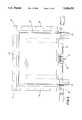
- FIG. 1is a front view of a first embodiment outlet gate assembly
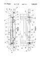
- FIG. 2is a side view of the assembly of FIG. 1 taken along line 2--2 of FIG. 1;
- FIG. 3is a top view of the assembly of FIG. 1;
- FIG. 4is a sectional view taken along line 4--4 of FIG. 1;
- FIGS. 5, 6, and 7are sectional views, partially broken away, taken generally along line 5--5 of FIG. 1 illustrating the operation of the assembly;
- FIG. 8is a front view of a second embodiment outlet gate assembly
- FIG. 9is a side view of the assembly of FIG. 8;
- FIG. 10is a sectional view taken along line 10--10 of FIG. 8;
- FIGS. 11, 12, and 13are sectional views, partially broken away, taken generally along line 11--11 of FIG. 8 illustrating the operation of the second embodiment outlet gate assembly.
- FIGS. 1 through 7illustrate the first embodiment outlet gate assembly.
- Outlet gate assembly 10includes a rectangular frame 12 having a rear frame member 14, a pair of side frame members 16, and a front frame member 18 defining a rectangular discharge opening 20. Extensions 22 of side frame members 16 project beyond the rear frame member 14. Rectangular gate assembly 10 is bolted to a discharge opening in the bottom of a hopper-type railway car to control the discharge of lading from the car.
- a rectangular plate 24is mounted in frame 12 and is movable between a closed position in which the plate completely closes opening 20 and an open position in which the plate is free of the opening.
- the plateextends through slot 26 formed in the rear side member 14 as shown in FIG. 2.
- the front and side edges of the platefit in grooves in the side and front frame members 16 and 18 to close opening 20.
- Conventional sealsare provided at slot 26 and at the grooves.
- a stop plate 32is secured to the bottom of the rear edge of plate 24 midway between the side frame members 16 and extends outwardly a distance beyond the rear edge of the plate. When the plate 24 is fully closed as shown in FIG. 4, the inner edge of the plate 32 engages the rear frame member 14. See FIG. 4.
- the plate 24is moved from the closed position out through slot 26 to the open position by an integrated plate drive 28 mounted on side frame member extensions 22.
- the driveincludes a pair of spaced parallel racks 30 mounted on the lower surface of plate 24, a square drive shaft 34 extending between and through side frame member extensions 22 and journalled in bearings 36 mounted on the extensions and a pair of pinion gears 38 on the drive shaft and meshed with the teeth of racks 30.
- the pinion gears 38are directly or fixedly connected to the drive shaft 34 and rotate with the drive shaft.
- the ends of the drive shaft 34extend outwardly or outboard of the frame side extensions 22.
- a pair of like slip sockets 40are mounted on the ends of drive shaft 34 outwardly of extensions 22.
- Each slip socketincludes a sleeve 42 rotatably mounted on the end of the drive shaft and a capstan 44 on the outer end of the sleeve.
- the slip socketis held on an end of the drive shaft by a slot and bolt connection 46.
- This connectionincludes a bolt 48 having a shank which extends through a pair of partial circumferential slots 50 formed in opposite sides of sleeve 42 and a bore 53 extending through the end of the drive shaft 34 in the sleeve.
- the slots 50are sufficiently long to allow slightly more than 45 degrees of relative rotation between the sleeve and the end of the drive shaft 34.
- Nut 52is secured to the end of the bolt to hold the bolt in place.
- Connection 46prevents axial shifting of the socket on the drive shaft while permitting relative rotation of the socket on the drive shaft.
- the plate drive 28includes a lost motion drive connection 53 between each slip socket and the end of the drive shaft on which the socket is mounted.
- Connection 53includes four like stop projections 54 on the interior wall of sleeve 42 located at 90 degree intervals spaced around the sleeve.
- the drive projections 54are each provided with a pair of flat contact surfaces. Rotation of the sleeve on the drive shaft in one direction moves the contact surfaces on one side of the projections against the drive shaft to rotate the drive shaft. Rotation of the sleeve on the drive shaft in the opposite direction moves the contact surfaces on the other side of the projections against with the drive shaft to rotate the drive shaft.
- the sleevehas 45 degrees of lost motion on the drive shaft, as indicated by the 45-degree spacing between adjacent projections.
- a latch lift cam 56is mounted on the outer surface of each sleeve 42 between collars 58 and 60 and includes sloped end surfaces 62 and a dwell surface 64 between the end surfaces.
- Latch shaft 66is located outside the front frame member 14 and extends across the width of frame 12 through holes formed in side frame member extensions 22 and in a pair of support plates 68 joined to front frame member 14. The ends of the latch shaft are located above lift cams 56 and are provided with follower arms 70 which extend generally downwardly from the latch shaft for engagement with cams 56.
- a latch 72 as shown in FIG. 4is secured to shaft 66 and extends generally forwardly from the shaft away from the front frame member 14.
- a downwardly projecting hook 74is provided on the free end of the latch and defines a plate-receiving recess 76 facing the front frame member.
- Rounded lift finger 75extends downwardly from the latch between the hook 74 and shaft 66.
- Springs 78are wrapped around the latch shaft with ends engaging a cross pin in the latch and the front frame member to bias the shaft, latch and follower arms in a clockwise direction as shown in FIG. 4 so that the hook end of the latch 72 is biased downwardly and arms 70 are biased toward sleeves 42.
- FIG. 4illustrates the assembly 10 with plate 24 in the closed position and with the latch 72 held in a downward position by springs 78 and hook 74 engaging the outer edge of stop plate 32.
- the edge of the plateforms a stop member.
- Lift finger 75extends into cut-out recess 79 in stop plate 32.
- the inner edge of the stop plateis flush against the cross frame member. The latch and cross member cooperate to prevent forward or rearward movement of plate 24 in frame 12.
- plate 32When plate 24 is fully closed as in FIG. 4, plate 32 is confined between the cross frame member 14 and hook 74 of latch 72.
- the springs 76hold the latch in the closed position to prevent accidental opening of the plate due to vibrations of the railway car during transit, coupling shocks, train action loadings and other inertial forces experienced by assembly 10 during loading and transport of the hopper railcar.
- the follower arms 70In this position, the follower arms 70 extend down toward the sleeves 42 and are in the path of opening movement of cams 56. Springs 78 hold the follower arms down in a position of FIG. 5 during the time the plate is locked closed.
- the gate assemblymay be opened by a worker from either side of the rail car by rotating one of the capstans 44 in an opening direction.
- the workermay rotate the capstan by using a power drive engaging the capstan or a pry bar having an end inserted into the capstan.
- Rotation of the slip socket after plate 24 is unlatchedfully collapses the lost motion connection 53 and moves the drive projections on the sleeve into engagement with the drive shaft to rotate the drive shaft 34.
- Rotation of the drive shaftrotates the pinion gears 38 meshed with racks 30 to move the plate outwardly in the direction of arrow 80 shown in FIG. 7 toward the open position.
- Upward rotation of the latchlifts finger 75 from recess 79.
- the front edge of plate 24engages the finger and further rotates the latch up so that the end of the latch 72 rides along the top of the plate 24 during opening and arms 70 are held above the cams 56 on both sockets 40.
- Springs 78hold the finger 75 against the top of plate 24.
- the driven capstanis rotated in a clockwise opening direction and drives the drive shaft in a clockwise direction to move the gate in the direction of arrow 80 until the gate is fully opened.
- the open gate assemblyis fully closed and latched by rotating either of the capstans in a closing direction.
- Initial closing rotation of the driven capstanwill rotate the sleeve to collapse the lost motion connection between the sleeve and the drive shaft and move the drive projections into engagement with the drive shaft for closing rotation of the drive shaft.
- Continued closing rotation of the capstanwill then rotate the drive shaft and pinion gears to move plate 24 inwardly.
- the spring 78holds latch 72 down against the surface plate 24 so that arms 70 are held above rotating cams 56.
- the lift finger 75falls into recess 79 to latch plate 24 closed and both arms 70 are lowered below the height of the dwell surfaces 64 of lift cams 56.
- the lift cam 56 of the driven socketis located circumferentially away from the lowered adjacent arm 70.
- the lift cam 56 of the non-driven slip socketis mounted on the adjacent end of the drive shaft through a lost motion connection 55 and may rotate on the shaft.
- the non-driven capstanis circumferentially located on the drive shaft with the lift cam either out of the path of downward movement of the adjacent arm 70 or positioned so that arm 70, when it falls under the influence of springs 78, engages an end surface 62 of the cam.
- the springs 78are sufficiently strong to push the arm 70 down and rotate the non-driven socket out of the path of movement of the arm. In this way, closing rotation of the driven socket moves the plate to the fully closed position with the plate 24 latched closed and both follower arms in position to unlatch the plate upon opening rotation of either capstan.
- FIGS. 8 through 13illustrate a second embodiment outlet gate assembly 100.
- Assembly 100includes a rectangular frame with front, side, and rear frame members like frame 12 of assembly 10.
- Plate 104is mounted in frame and extends through a slot 106, like slot 26, formed in the rear member of frame.
- An integrated plate drive 108moves plate 104 between the closed and opened positions.
- Drive 108includes a square drive shaft 110 which is journalled in a pair of bearings 112 mounted on the rear extensions of frame member with the ends of the drive shaft extending outwardly of the extensions.
- a pair of pinion gears 114are directly mounted on the drive shaft 110 and rotate with the drive shaft. Gears 114 mesh with racks 116 secured to the lower surface of plate 104 such that rotation of the drive shaft shifts the plate between the open and closed positions.
- a first slip socket 118is mounted on the end of the drive shaft on the left of gate assembly 100 as shown in FIG. 8.
- a second slip socket 120is mounted on the right end of the drive shaft. Each slip socket is held on the drive shaft by a slot and bolt connection 122, like connection 46 of the first embodiment gate assembly 10.
- connection 122holds the sockets on the drive shaft and permit relative rotation between each socket and the drive shaft.
- Latch lift cam 164is mounted on sleeve 126.
- Collar 124is located between the first slip socket 118 and the adjacent bearing 112 and is directly secured to drive shaft 110 to rotate with the drive shaft.
- the first slip socket 118includes a sleeve 126 rotatably mounted on the drive shaft and a capstan 128 joined to the sleeve.
- Four 90 degree spaced drive projections 130like projections 54, extend inwardly from sleeve 126 to engage the sides of the square drive shaft 110 and rotate the shaft either clockwise or counterclockwise, depending upon the direction of rotation of capstan 128.
- the projectionsform a 45 degree lost motion drive connection between the sleeve and the shaft.
- Slip socket 120includes a sleeve 132 rotatably mounted on an end of the drive shaft 110 and a capstan 134 located outwardly of the sleeve.
- Drive projectionslike projections 130 are provided on the inner surface of sleeve 132 to engage the sides of the drive shaft and rotate the drive shaft to open or close the gate, depending upon the direction of rotation of capstan 134. These projections form a 45 degree lost motion drive connection between the sleeve and the shaft.
- a latch lift cam 164is mounted on sleeve 132.
- Elongated rotatable latch shaft 136extends across the rear of frame through holes formed in the extensions 138 and 140 of frame side members and through a support plate 142 mounted on the rear frame member.
- the ends of the latch shaftextend outwardly of the extensions 138 and 140 above sleeves 126 and 132.
- Cam follower arms 144are mounted on the ends of the latch shaft and extend down toward sleeves 126 and 132.
- a latch 146is mounted on the end of the latch shaft above collar 124.
- the latchincludes a hook end 148 defining a recess 150 overlying the front side of the sleeve 124.
- Spring 152is wound around shaft 136 and includes ends engaging extension 138 and latch 146 to bias the latch, shaft and follower arms in a clockwise direction as shown in FIGS.
- the latchincludes a stop end 154 away from hook 147.
- the end 154engages flange 156 on the front member of frame 102 to limit clockwise rotation of the shaft, latch and arms.
- Latch lift finger 158is mounted on the center of shaft 136 above plate 104.
- Latch stop finger 160is secured to sleeve 124 and rotates with the sleeve and drive shaft 110.
- Finger 160includes a tip 162 which fits in recess 150 to latch plate 104 in the closed position through drive shaft 110, pinion gears 114 and racks 116.
- a latch lift cam 164having end and dwell surfaces is secured to each rotary sleeve 126 and 132 in position to engage a follower arm 144 upon rotation of the sleeve.
- latch 146When plate 104 is fully closed, as shown in FIG. 11, latch 146 is lowered with the tip 162 of stop finger 160 seated in recess 150 of latch 146. The engagement between the stop finger and latch prevents collar 124, drive shaft 110 and pinion gears 114 from rotating in an opening direction. Racks 116 engage the latches gears 114 to hold plate 104 latched closed.
- the plate 104is unlatched for opening in direction of arrow 166 shown in FIG. 11 by opening rotation of either capstan 128 or 134. Opening of gate assembly 100 by rotating capstan 128 in the clockwise opening direction first rotates the latch lift cam 164 on sleeve 126 clockwise to engage adjacent cam follower arm 144 and rotate the arm, shaft 136 and latch 146 counterclockwise so that latch hook 147 is rotated out of engagement and above the tip of stationary stop finger or member 160. Rotation of latch 146 above the stop finger occurs during collapse of the lost motion connection between the sleeve 126 and drive shaft 110 while the drive shaft is stationary.
- latch lift finger 158 on shaft 136extends down in front of the plate 104.
- Rotation of shaft 136 to lift the latch out of engagement with the stop fingerrotates the lift finger upwardly.
- the leading edge of plate 104extends under the finger so the finger rests on plate 104 and holds latch 146 above stop finger 160 and arms 144 above the lift cams 164 during opening.
- Continued opening rotation of the driven capstan 128moves the plate 104 to the fully opened position with the latch 146 and follower arms 144 held up out of engagement above latch cams 164 and the stop finger 160.
- Opening of plate 104has been described in response to opening rotation of slip socket 128.
- the platemay also be moved from the closed position to the open position by opening rotation of capstan 134 on slip socket 120.
- Initial rotation of the slip socket 120rotates the lift cam 164 on the socket into engagement with adjacent cam follower arm 144 during collapse of the lost motion connection between the slip socket and the drive shaft 110 to rotate latch shaft 136 in a clockwise direction and lift the latch 146 out of engagement with the stop finger 160 prior to collapse of the lost motion connection and initial rotation of the drive shaft 110 to open the gate.
- Plate 104is closed from the open position by rotating either of the slip sockets 118 and 120 in a closing direction to collapse the lost motion connection between the driven socket and then move the plate in a closing direction.
- finger 158is held against the upper surface of the plate by spring 152 to hold the latch 146 above rotating stop finger 116 and both follower arms 144 above the rotating latch lift cams 164 on the slip sockets.
- latch stop finger 160When the plate 104 is fully closed, latch stop finger 160 is in the position of FIG. 10 and spring 152 has rotated latch 146 down to position hook 148 in engagement with the tip 162 of the stop finger, thereby positively latching the plate closed.
- the latch lift cams 164do not prevent downward rotation of the cam follower arms 144, although the follower arm 144 adjacent the non-driven socket may be lowered into engagement with one side of the lift cam 164 on the non-driven socket to rotate the socket through a slight angle on the drive shaft so that the cam does not obstruct latching of the plate.
- the lost motion connection between the slip sockets and the drive shaft in both disclosed embodimentsare located at the ends of the drive shafts and are readily accessible during assembly of the integrated plate drives. This ready accessibility of the lost motion connections facilitates proper timing of the drives, both at the original equipment manufacturer's shops and at the shop of railway car manufacturers.
- Railway car manufacturersconventionally disassemble railway car gate assemblies in the process of building hopper cars using the gate assemblies. After disassembly, it is necessary to reassemble the gates and properly time the integrated gate drives.
- the locations of the lost motion connections between the slip sockets and the drive shaft at the sides of the framesfacilitates proper timing of the gates, particularly when the assembly is done by workers in manufacturer's yards who are not specifically trained to assemble gates.
- the lift cams and follower arms of both embodiments of the disclosed gate assembliesare located on the sides of the assembly and are readily available for inspection by workers to determine whether they are working properly. Further, the wiping action between the lift cams and the arms cleans the contact areas between the cams and arms to facilitate proper actuation of the lost motion drives. Likewise, the latch and stop finger of gate assembly 100 are located on one side of the assembly where they may easily be inspected to assure proper operation.
Landscapes
- Engineering & Computer Science (AREA)
- Transportation (AREA)
- Mechanical Engineering (AREA)
- Transmission Devices (AREA)
Abstract
Description
Claims (32)
Priority Applications (3)
| Application Number | Priority Date | Filing Date | Title |
|---|---|---|---|
| US08/499,930US5584251A (en) | 1995-07-10 | 1995-07-10 | Railway car outlet gate assembly with automatic lock |
| CA002166957ACA2166957A1 (en) | 1995-07-10 | 1996-01-10 | Railway car outlet gate assembly with automatic lock |
| US08/705,322US5671684A (en) | 1995-07-10 | 1996-08-29 | Railway car outlet gate assembly with automatic lock |
Applications Claiming Priority (1)
| Application Number | Priority Date | Filing Date | Title |
|---|---|---|---|
| US08/499,930US5584251A (en) | 1995-07-10 | 1995-07-10 | Railway car outlet gate assembly with automatic lock |
Related Child Applications (1)
| Application Number | Title | Priority Date | Filing Date |
|---|---|---|---|
| US08/705,322ContinuationUS5671684A (en) | 1995-07-10 | 1996-08-29 | Railway car outlet gate assembly with automatic lock |
Publications (1)
| Publication Number | Publication Date |
|---|---|
| US5584251Atrue US5584251A (en) | 1996-12-17 |
Family
ID=23987334
Family Applications (2)
| Application Number | Title | Priority Date | Filing Date |
|---|---|---|---|
| US08/499,930Expired - LifetimeUS5584251A (en) | 1995-07-10 | 1995-07-10 | Railway car outlet gate assembly with automatic lock |
| US08/705,322Expired - LifetimeUS5671684A (en) | 1995-07-10 | 1996-08-29 | Railway car outlet gate assembly with automatic lock |
Family Applications After (1)
| Application Number | Title | Priority Date | Filing Date |
|---|---|---|---|
| US08/705,322Expired - LifetimeUS5671684A (en) | 1995-07-10 | 1996-08-29 | Railway car outlet gate assembly with automatic lock |
Country Status (2)
| Country | Link |
|---|---|
| US (2) | US5584251A (en) |
| CA (1) | CA2166957A1 (en) |
Cited By (11)
| Publication number | Priority date | Publication date | Assignee | Title |
|---|---|---|---|---|
| US5829359A (en)* | 1996-09-13 | 1998-11-03 | Miner Enterprises, Inc. | Railway hopper car discharge gate assembly |
| US6012397A (en)* | 1998-01-08 | 2000-01-11 | Keystone Industries, Inc. | Railway car outlet gate assembly with inertial latch |
| US6067912A (en)* | 1997-09-22 | 2000-05-30 | Trn Business Trust | Automated discharge system for hopper car |
| US6073562A (en)* | 1998-04-09 | 2000-06-13 | Cozine; Claud W. | Railway car outlet gate assembly with compact inertial latch |
| US20050263031A1 (en)* | 2004-05-28 | 2005-12-01 | Early Stephen R | Drive system for a railway hopper car discharge gate |
| US20060016104A1 (en)* | 2004-07-07 | 2006-01-26 | Metso Minerals ( Tampere) Oy | Feeder hopper, a method for locking the walls of a feeder hopper and a locking means |
| US20060042499A1 (en)* | 2004-08-25 | 2006-03-02 | Fortuna Rudolph S | Lock assembly for a gate assembly of a railroad hopper car |
| US20070089639A1 (en)* | 2005-10-21 | 2007-04-26 | Fortuna Rudolph S | Railcar gate assembly operating shaft assembly |
| US10315668B2 (en) | 2017-01-09 | 2019-06-11 | Aero Transportation Products, Inc. | Hopper car gate with multiple openings |
| US20210101515A1 (en)* | 2019-10-07 | 2021-04-08 | Kelly L. Menz | Grain trailer |
| CN116691744A (en)* | 2023-05-09 | 2023-09-05 | 国能铁路装备有限责任公司 | Bottom door opening and closing mechanism |
Families Citing this family (13)
| Publication number | Priority date | Publication date | Assignee | Title |
|---|---|---|---|---|
| US6263803B1 (en)* | 1998-09-18 | 2001-07-24 | Miner Enterprises, Inc. | Gate assembly for a railroad hopper car |
| US6363863B1 (en) | 2000-07-18 | 2002-04-02 | Miner Enterprises, Inc. | Gate assembly for a railroad hopper car |
| US7171908B2 (en)* | 2003-03-19 | 2007-02-06 | Wabtec Holding Corp. | High/Low passenger ingress and egress conversion for transit vehicle |
| US6899038B2 (en) | 2003-10-15 | 2005-05-31 | Miner Enterprises, Inc. | Railroad hopper car discharge gate assembly |
| US7367271B2 (en)* | 2004-01-30 | 2008-05-06 | Aero Transportation Products, Inc. | Railway hopper car discharge gate |
| US7497170B2 (en)* | 2005-10-21 | 2009-03-03 | Powerbrace Corporation | Operating shaft assembly for railcars |
| US9090198B2 (en)* | 2011-06-30 | 2015-07-28 | Owen Industries, Inc. | Hopper trailer with auger and gravity discharge |
| US8746152B2 (en) | 2011-09-15 | 2014-06-10 | Miner Enterprises, Inc. | Low profile discharge gate assembly for a railroad hopper car |
| US8752487B2 (en) | 2011-09-15 | 2014-06-17 | Miner Enterprises, Inc. | Low profile discharge gate assembly for a railroad hopper car |
| US9592837B2 (en)* | 2013-11-04 | 2017-03-14 | Salco Products, Inc. | Valve for outlet gate assembly for hopper cars |
| US9393970B2 (en) | 2014-04-22 | 2016-07-19 | Miner Enterprises, Inc. | Railroad hopper car discharge gate assembly and related method for influencing gravitational discharge of material from a railroad hopper car |
| CN105329247A (en)* | 2015-11-30 | 2016-02-17 | 南车长江车辆有限公司 | Bottom door anti-theft device of railway grain hopper wagon |
| US20230019629A1 (en)* | 2021-07-16 | 2023-01-19 | A. Stucki Company | Opening stop device for railway freight car door outlet gates |
Citations (31)
| Publication number | Priority date | Publication date | Assignee | Title |
|---|---|---|---|---|
| US1499735A (en)* | 1919-02-21 | 1924-07-01 | Cons Car Heating Co | Car-door-operating mechanism |
| US1515834A (en)* | 1923-02-16 | 1924-11-18 | Entpr Railway Equipment Co | Door-operating mechanism |
| US1627801A (en)* | 1926-01-25 | 1927-05-10 | Edwin C Mitchell | Hopper-car door-operating device |
| US2142236A (en)* | 1936-06-13 | 1939-01-03 | Entpr Railway Equipment Co | Load discharging car |
| US2644408A (en)* | 1949-04-09 | 1953-07-07 | Entpr Railway Equipment Co | Gate closing and locking mechanism for discharge outlets of car hoppers |
| US2749770A (en)* | 1952-09-18 | 1956-06-12 | Entpr Railway Equipment Co | Operating head for rotating shaft of hopper closure |
| US2893327A (en)* | 1953-09-30 | 1959-07-07 | Magor Car Corp | Door operating motor means for gable bottom cars |
| US3082703A (en)* | 1958-06-06 | 1963-03-26 | Entpr Railway Equipment Co | Sliding closure outlet frame assembly |
| US3110270A (en)* | 1957-12-09 | 1963-11-12 | Unitcast Corp | Discharge gate operating assembly |
| US3316859A (en)* | 1963-02-04 | 1967-05-02 | Unitcast Corp | Hopper door operating and latching assembly |
| US3387570A (en)* | 1966-09-22 | 1968-06-11 | Acf Ind Inc | Sequential hopper gate operating mechanism |
| US3397654A (en)* | 1967-02-10 | 1968-08-20 | Acf Ind Inc | Sliding hopper gate operating mechanism |
| US3682105A (en)* | 1970-08-17 | 1972-08-08 | Pullman Inc | Automatic hopper gate lock |
| US3683820A (en)* | 1970-09-01 | 1972-08-15 | Midland Ross Corp | Automatic hopper gate lock |
| US3709152A (en)* | 1970-12-28 | 1973-01-09 | Pullman Inc | Hopper car gate latching mechanism |
| US3710729A (en)* | 1970-01-02 | 1973-01-16 | Pullman Inc | Vehicle hopper door operating mechanism |
| US3837294A (en)* | 1972-12-04 | 1974-09-24 | Acf Ind Inc | Cammed railway hopper gate latching apparatus |
| US3893398A (en)* | 1974-06-14 | 1975-07-08 | Miner Enterprises | Lock means for slide gate of hopper outlet assembly |
| US3933100A (en)* | 1974-07-31 | 1976-01-20 | Acf Industries, Incorporated | Hopper gate actuating mechanism |
| US3956996A (en)* | 1974-06-14 | 1976-05-18 | Miner Enterprises, Inc. | Pivoted slide gate lock |
| US4224879A (en)* | 1978-06-12 | 1980-09-30 | Keystone Industries, Inc. | Railway hopper car door latch |
| US4256042A (en)* | 1979-10-04 | 1981-03-17 | Miner Enterprises, Inc. | Railway hopper car sliding gate lock |
| US4262603A (en)* | 1978-10-26 | 1981-04-21 | Pullman Incorporated | Door locking arrangement for railway hopper car |
| US4301741A (en)* | 1979-10-22 | 1981-11-24 | Holland Company | Hopper car outlet gate assembly with self cleaning gear and rack actuation arrangement |
| US4432267A (en)* | 1982-04-29 | 1984-02-21 | Feller Terry L | Adjustable neck-body joint for guitar-like instrument |
| US4664038A (en)* | 1983-07-11 | 1987-05-12 | General American Transportation Corporation | Door latch control apparatus for hopper vehicle |
| US4766820A (en)* | 1987-06-03 | 1988-08-30 | Thrall Car Manufacturing Company | Hopper car with automatic discharge door mechanism |
| US4843974A (en)* | 1987-06-03 | 1989-07-04 | Thrall Car Manufacturing Company | Hopper car with automatic discharge door mechanism |
| US5353713A (en)* | 1993-10-01 | 1994-10-11 | White Welding And Mfg., Inc. | Apparatus for controlling operation of a railcar discharge gate assembly having a lost motion mechanism for unlocking the gate prior to movement |
| US5448955A (en)* | 1994-09-12 | 1995-09-12 | Acf Industries | Gravity outlet latching mechanism |
| US5507235A (en)* | 1994-01-25 | 1996-04-16 | Acf Industries Incorporated | Gravity outlet |
Family Cites Families (23)
| Publication number | Priority date | Publication date | Assignee | Title |
|---|---|---|---|---|
| US2340519A (en)* | 1940-10-14 | 1944-02-01 | George B Dorey | Discharge outlet for railway cars and the like |
| US2479292A (en)* | 1946-03-14 | 1949-08-16 | Entpr Railway Equipment Co | Door operating mechanism for dump cars |
| US3344748A (en)* | 1964-03-09 | 1967-10-03 | Continental Transp Appliances | Hopper car discharge outlet assembly |
| US3248026A (en)* | 1964-07-29 | 1966-04-26 | Acf Ind Inc | Hopper structure for pneumatically unloading bulk materials |
| US3241730A (en)* | 1964-11-12 | 1966-03-22 | Continental Transp Appliances | Operating means for sliding gate |
| US3415204A (en)* | 1966-08-03 | 1968-12-10 | Hugh H. Pase | Hopper gate sealing means |
| US3552323A (en)* | 1968-02-20 | 1971-01-05 | Continental Transport Applianc | Sliding hopper gate actuating mechanism |
| US3630154A (en)* | 1969-09-22 | 1971-12-28 | Pullman Inc | Rack-and-pinion-actuated railway hopper car gate |
| US3631813A (en)* | 1969-11-03 | 1972-01-04 | George B Dorey | Rack and toggle hopper gate-actuating mechanism |
| US3707126A (en)* | 1970-07-13 | 1972-12-26 | Keystone Ind Inc | Hopper gate latching mechanism |
| US3779172A (en)* | 1971-03-24 | 1973-12-18 | Acf Ind Inc | Railway hopper car outlet |
| US3958514A (en)* | 1973-12-28 | 1976-05-25 | Acf Industries, Incorporated | Automatic hopper gate locking mechanism |
| US3877392A (en)* | 1973-12-28 | 1975-04-15 | Acf Ind Inc | Automatic gate locking mechanism |
| US4006692A (en)* | 1975-05-02 | 1977-02-08 | Holland Company | Hopper car outlet gate and seal |
| US4099468A (en)* | 1976-07-15 | 1978-07-11 | Pullman Incorporated | Lock for a hopper car outlet gate |
| US4094254A (en)* | 1976-12-27 | 1978-06-13 | Koranda Clarence J | Lock for railway hopper car gate railway car gate lock |
| US4214536A (en)* | 1977-10-26 | 1980-07-29 | Acf Industries, Incorporated | Hopper outlet having vertically movable door bearing |
| US4253400A (en)* | 1979-06-14 | 1981-03-03 | Miner Enterprises, Inc. | Railway hopper car sliding gate closing mechanism |
| US4342267A (en)* | 1980-08-13 | 1982-08-03 | Evans Products Company | Hopper discharge unit with sliding gate |
| US4450773A (en)* | 1981-01-23 | 1984-05-29 | The Youngstown Steel Door Co. | Sliding gate for a railroad hopper car |
| US4534298A (en)* | 1983-02-16 | 1985-08-13 | Keystone Industries, Inc. | Lock and seal for hopper outlet |
| CA1331720C (en)* | 1989-04-28 | 1994-08-30 | Bert J. Bowler | Unloading gate for bulk material handling containers |
| US5272987A (en)* | 1993-01-29 | 1993-12-28 | Keystone Railway Equipment Company | Lock for railway hopper car unloading gate |
- 1995
- 1995-07-10USUS08/499,930patent/US5584251A/ennot_activeExpired - Lifetime
- 1996
- 1996-01-10CACA002166957Apatent/CA2166957A1/ennot_activeAbandoned
- 1996-08-29USUS08/705,322patent/US5671684A/ennot_activeExpired - Lifetime
Patent Citations (31)
| Publication number | Priority date | Publication date | Assignee | Title |
|---|---|---|---|---|
| US1499735A (en)* | 1919-02-21 | 1924-07-01 | Cons Car Heating Co | Car-door-operating mechanism |
| US1515834A (en)* | 1923-02-16 | 1924-11-18 | Entpr Railway Equipment Co | Door-operating mechanism |
| US1627801A (en)* | 1926-01-25 | 1927-05-10 | Edwin C Mitchell | Hopper-car door-operating device |
| US2142236A (en)* | 1936-06-13 | 1939-01-03 | Entpr Railway Equipment Co | Load discharging car |
| US2644408A (en)* | 1949-04-09 | 1953-07-07 | Entpr Railway Equipment Co | Gate closing and locking mechanism for discharge outlets of car hoppers |
| US2749770A (en)* | 1952-09-18 | 1956-06-12 | Entpr Railway Equipment Co | Operating head for rotating shaft of hopper closure |
| US2893327A (en)* | 1953-09-30 | 1959-07-07 | Magor Car Corp | Door operating motor means for gable bottom cars |
| US3110270A (en)* | 1957-12-09 | 1963-11-12 | Unitcast Corp | Discharge gate operating assembly |
| US3082703A (en)* | 1958-06-06 | 1963-03-26 | Entpr Railway Equipment Co | Sliding closure outlet frame assembly |
| US3316859A (en)* | 1963-02-04 | 1967-05-02 | Unitcast Corp | Hopper door operating and latching assembly |
| US3387570A (en)* | 1966-09-22 | 1968-06-11 | Acf Ind Inc | Sequential hopper gate operating mechanism |
| US3397654A (en)* | 1967-02-10 | 1968-08-20 | Acf Ind Inc | Sliding hopper gate operating mechanism |
| US3710729A (en)* | 1970-01-02 | 1973-01-16 | Pullman Inc | Vehicle hopper door operating mechanism |
| US3682105A (en)* | 1970-08-17 | 1972-08-08 | Pullman Inc | Automatic hopper gate lock |
| US3683820A (en)* | 1970-09-01 | 1972-08-15 | Midland Ross Corp | Automatic hopper gate lock |
| US3709152A (en)* | 1970-12-28 | 1973-01-09 | Pullman Inc | Hopper car gate latching mechanism |
| US3837294A (en)* | 1972-12-04 | 1974-09-24 | Acf Ind Inc | Cammed railway hopper gate latching apparatus |
| US3893398A (en)* | 1974-06-14 | 1975-07-08 | Miner Enterprises | Lock means for slide gate of hopper outlet assembly |
| US3956996A (en)* | 1974-06-14 | 1976-05-18 | Miner Enterprises, Inc. | Pivoted slide gate lock |
| US3933100A (en)* | 1974-07-31 | 1976-01-20 | Acf Industries, Incorporated | Hopper gate actuating mechanism |
| US4224879A (en)* | 1978-06-12 | 1980-09-30 | Keystone Industries, Inc. | Railway hopper car door latch |
| US4262603A (en)* | 1978-10-26 | 1981-04-21 | Pullman Incorporated | Door locking arrangement for railway hopper car |
| US4256042A (en)* | 1979-10-04 | 1981-03-17 | Miner Enterprises, Inc. | Railway hopper car sliding gate lock |
| US4301741A (en)* | 1979-10-22 | 1981-11-24 | Holland Company | Hopper car outlet gate assembly with self cleaning gear and rack actuation arrangement |
| US4432267A (en)* | 1982-04-29 | 1984-02-21 | Feller Terry L | Adjustable neck-body joint for guitar-like instrument |
| US4664038A (en)* | 1983-07-11 | 1987-05-12 | General American Transportation Corporation | Door latch control apparatus for hopper vehicle |
| US4766820A (en)* | 1987-06-03 | 1988-08-30 | Thrall Car Manufacturing Company | Hopper car with automatic discharge door mechanism |
| US4843974A (en)* | 1987-06-03 | 1989-07-04 | Thrall Car Manufacturing Company | Hopper car with automatic discharge door mechanism |
| US5353713A (en)* | 1993-10-01 | 1994-10-11 | White Welding And Mfg., Inc. | Apparatus for controlling operation of a railcar discharge gate assembly having a lost motion mechanism for unlocking the gate prior to movement |
| US5507235A (en)* | 1994-01-25 | 1996-04-16 | Acf Industries Incorporated | Gravity outlet |
| US5448955A (en)* | 1994-09-12 | 1995-09-12 | Acf Industries | Gravity outlet latching mechanism |
Non-Patent Citations (6)
| Title |
|---|
| Advertisement Geaps Snap Lock Gravity Outlet Gates , Trinity Industries, Inc., RSB Geaps 0995 2.* |
| Advertisement-"Geaps-Snap-Lock Gravity Outlet Gates", Trinity Industries, Inc., RSB-Geaps 0995-2. |
| Association Of American Railroads, Specification For New Gravity Outlet Gates On Covered Hopper Cars, Sep. 1, 1992, C 11 To C 13.4.* |
| Association Of American Railroads, Specification For New Gravity Outlet Gates On Covered Hopper Cars, Sep. 1, 1992, C-11 To C-13.4. |
| Miner Promotional Sheet No. Mem 1038 922 1M (Sep. 18, 1992).* |
| Miner Promotional Sheet No. Mem 1038-922-1M (Sep. 18, 1992). |
Cited By (22)
| Publication number | Priority date | Publication date | Assignee | Title |
|---|---|---|---|---|
| US5829359A (en)* | 1996-09-13 | 1998-11-03 | Miner Enterprises, Inc. | Railway hopper car discharge gate assembly |
| AU718745B2 (en)* | 1996-09-13 | 2000-04-20 | Miner Enterprises Inc. | Railway hopper car discharge gate assembly |
| US6067912A (en)* | 1997-09-22 | 2000-05-30 | Trn Business Trust | Automated discharge system for hopper car |
| US6012397A (en)* | 1998-01-08 | 2000-01-11 | Keystone Industries, Inc. | Railway car outlet gate assembly with inertial latch |
| US6073562A (en)* | 1998-04-09 | 2000-06-13 | Cozine; Claud W. | Railway car outlet gate assembly with compact inertial latch |
| US7171907B2 (en)* | 2004-05-28 | 2007-02-06 | Aero Transportation Products | Drive system for a railway hopper car discharge gate |
| US20050263031A1 (en)* | 2004-05-28 | 2005-12-01 | Early Stephen R | Drive system for a railway hopper car discharge gate |
| US20090263194A1 (en)* | 2004-07-07 | 2009-10-22 | Metso Minerals Inc, | Feeder hopper, a method for locking the walls of a feeder hopper and a locking means |
| US20060016104A1 (en)* | 2004-07-07 | 2006-01-26 | Metso Minerals ( Tampere) Oy | Feeder hopper, a method for locking the walls of a feeder hopper and a locking means |
| US20110089717A1 (en)* | 2004-07-07 | 2011-04-21 | Metso Minerals Inc. | Feeder hopper, a method for locking the walls of a feeder hopper and a locking means |
| US7568858B2 (en)* | 2004-07-07 | 2009-08-04 | Metso Minerals Inc. | Feeder hopper, a method for locking the walls of a feeder hopper and a locking means |
| US8182172B2 (en) | 2004-07-07 | 2012-05-22 | Metso Minerals Inc. | Feeder hopper, a method for locking the walls of a feeder hopper and a locking means |
| US7234401B2 (en) | 2004-08-25 | 2007-06-26 | Powerbrace Corporation | Lock assembly for a gate assembly of a railroad hopper car |
| US20060249047A1 (en)* | 2004-08-25 | 2006-11-09 | Fortuna Rudolph S | Lock assembly for a gate assembly of a railroad hopper car |
| US20060042499A1 (en)* | 2004-08-25 | 2006-03-02 | Fortuna Rudolph S | Lock assembly for a gate assembly of a railroad hopper car |
| US7140303B2 (en) | 2004-08-25 | 2006-11-28 | Powerbrace Corporation | Lock assembly for a gate assembly of a railroad hopper car |
| US20070089639A1 (en)* | 2005-10-21 | 2007-04-26 | Fortuna Rudolph S | Railcar gate assembly operating shaft assembly |
| US7793595B2 (en)* | 2005-10-21 | 2010-09-14 | Miner Enterprises, Inc. | Railcar gate assembly operating shaft assembly |
| US10315668B2 (en) | 2017-01-09 | 2019-06-11 | Aero Transportation Products, Inc. | Hopper car gate with multiple openings |
| US20210101515A1 (en)* | 2019-10-07 | 2021-04-08 | Kelly L. Menz | Grain trailer |
| US11618365B2 (en)* | 2019-10-07 | 2023-04-04 | Trail King Industries, Inc. | Grain trailer |
| CN116691744A (en)* | 2023-05-09 | 2023-09-05 | 国能铁路装备有限责任公司 | Bottom door opening and closing mechanism |
Also Published As
| Publication number | Publication date |
|---|---|
| US5671684A (en) | 1997-09-30 |
| CA2166957A1 (en) | 1997-01-11 |
Similar Documents
| Publication | Publication Date | Title |
|---|---|---|
| US5584251A (en) | Railway car outlet gate assembly with automatic lock | |
| CA2172707C (en) | Apparatus for controlling operation of a railcar discharge gate assembly | |
| US5163372A (en) | Unit for actuating gates of a hopper railroad car | |
| US4450773A (en) | Sliding gate for a railroad hopper car | |
| US5829359A (en) | Railway hopper car discharge gate assembly | |
| CN111845802B (en) | Limiting device for hopper car bottom door opening and closing mechanism | |
| CN104648414A (en) | Bottom door locking system of railroad hopper car | |
| US3872983A (en) | Freight carrying device | |
| US5448955A (en) | Gravity outlet latching mechanism | |
| US2020863A (en) | Railway car | |
| CN212828345U (en) | A limiting device for the opening and closing mechanism of the bottom door of a hopper car | |
| US6000564A (en) | Roller equipped uncoupling cam | |
| DE112010004715T5 (en) | Vehicle door lock | |
| US2751860A (en) | Removable closure for discharged outlet for railway car hopper | |
| US3896741A (en) | Freight carrying device | |
| US2083708A (en) | Refrigerator car door | |
| US3204578A (en) | Slide gate assembly | |
| US4213725A (en) | Double locking door latch mechanism for railway hopper cars | |
| US3029956A (en) | Car coupler | |
| US3419165A (en) | Apparatus and system for operating railroad car dumper doors | |
| US3139042A (en) | Hopper door locking mechanism | |
| US1132683A (en) | Car-door-operating mechanism. | |
| US1912846A (en) | Door | |
| KR200343179Y1 (en) | A door open and shut apparatus od hopper freight rail cars | |
| US1627801A (en) | Hopper-car door-operating device |
Legal Events
| Date | Code | Title | Description |
|---|---|---|---|
| AS | Assignment | Owner name:KEYSTONE INDUSTRIES, INC., PENNSYLVANIA Free format text:ASSIGNMENT OF ASSIGNORS INTEREST;ASSIGNOR:LUCAS, ANTHONY L.;REEL/FRAME:007977/0338 Effective date:19960513 | |
| STCF | Information on status: patent grant | Free format text:PATENTED CASE | |
| CC | Certificate of correction | ||
| FEPP | Fee payment procedure | Free format text:PAYOR NUMBER ASSIGNED (ORIGINAL EVENT CODE: ASPN); ENTITY STATUS OF PATENT OWNER: SMALL ENTITY | |
| FPAY | Fee payment | Year of fee payment:4 | |
| AS | Assignment | Owner name:CITICORP USA, INC., C/O CITIBANK DELAWARE, DELAWAR Free format text:SECURITY INTEREST;ASSIGNOR:MEANS INDUSTRIES, INC.;REEL/FRAME:011231/0282 Effective date:20000929 Owner name:CITICORP USA, INC., DELAWARE Free format text:SECURITY INTEREST;ASSIGNOR:KEYSTONE INDUSTRIES, INC.;REEL/FRAME:011231/0636 Effective date:20000929 | |
| AS | Assignment | Owner name:AERO TRANSPORTATION PRODUCTS, INC., MISSOURI Free format text:ASSIGNMENT OF ASSIGNORS INTEREST;ASSIGNOR:ASF-KEYSTONE, INC.;REEL/FRAME:012865/0754 Effective date:20011012 Owner name:ASF-KEYSTONE, INC., ILLINOIS Free format text:ASSIGNMENT OF ASSIGNORS INTEREST;ASSIGNOR:KEYSTONE INDUSTRIES, INC.;REEL/FRAME:012865/0842 Effective date:20011012 | |
| AS | Assignment | Owner name:AERO TRANSPORTATION PRODUCTS, INC., MISSOURI Free format text:RELEASE AGREEMENT;ASSIGNOR:AMSTED INDUSTRIES, INCORPORATED;REEL/FRAME:013177/0886 Effective date:20011012 | |
| FEPP | Fee payment procedure | Free format text:PAT HOLDER CLAIMS SMALL ENTITY STATUS, ENTITY STATUS SET TO SMALL (ORIGINAL EVENT CODE: LTOS); ENTITY STATUS OF PATENT OWNER: SMALL ENTITY | |
| FPAY | Fee payment | Year of fee payment:8 | |
| FPAY | Fee payment | Year of fee payment:12 | |
| REMI | Maintenance fee reminder mailed | ||
| AS | Assignment | Owner name:BANK OF AMERICA, N.A., AS THE SUCCESSOR COLLATERAL Free format text:INTELLECTUAL PROPERTY SECURITY INTEREST ASSIGNMENT AGREEMENT;ASSIGNOR:CITICORP NORTH AMERICA, INC., AS THE RESIGNING COLLATERAL AGENT (AS SUCCESSOR IN INTEREST OF CITICORP USA, INC.);REEL/FRAME:023471/0036 Effective date:20090930 | |
| AS | Assignment | Owner name:WELLS FARGO BANK, NATIONAL ASSOCIATION, AS SUCCESSOR AGENT, NORTH CAROLINA Free format text:NOTICE OF SUCCESSOR AGENT AND ASSIGNMENT OF SECURITY INTEREST AT REEL/FRAME 023471/0036;ASSIGNOR:BANK OF AMERICA, N.A., AS THE RESIGNING AGENT;REEL/FRAME:070156/0759 Effective date:20250206 |