US5583520A - Matched input antenna for a portable radio - Google Patents
Matched input antenna for a portable radioDownload PDFInfo
- Publication number
- US5583520A US5583520AUS08/508,939US50893995AUS5583520AUS 5583520 AUS5583520 AUS 5583520AUS 50893995 AUS50893995 AUS 50893995AUS 5583520 AUS5583520 AUS 5583520A
- Authority
- US
- United States
- Prior art keywords
- arm coil
- ground
- hot
- antenna element
- coil
- Prior art date
- Legal status (The legal status is an assumption and is not a legal conclusion. Google has not performed a legal analysis and makes no representation as to the accuracy of the status listed.)
- Expired - Lifetime
Links
- 230000008878couplingEffects0.000claimsabstractdescription16
- 238000010168coupling processMethods0.000claimsabstractdescription16
- 238000005859coupling reactionMethods0.000claimsabstractdescription16
- 230000001939inductive effectEffects0.000abstract1
- 230000005404monopoleEffects0.000description3
- 230000004323axial lengthEffects0.000description2
- 239000004033plasticSubstances0.000description2
- RYGMFSIKBFXOCR-UHFFFAOYSA-NCopperChemical compound[Cu]RYGMFSIKBFXOCR-UHFFFAOYSA-N0.000description1
- 238000000576coating methodMethods0.000description1
- 239000004020conductorSubstances0.000description1
- 229910052802copperInorganic materials0.000description1
- 239000010949copperSubstances0.000description1
- 230000007423decreaseEffects0.000description1
- 230000000694effectsEffects0.000description1
- 238000012986modificationMethods0.000description1
- 230000004048modificationEffects0.000description1
- 238000010137moulding (plastic)Methods0.000description1
- 239000006223plastic coatingSubstances0.000description1
- 239000002985plastic filmSubstances0.000description1
Images

Classifications
- H—ELECTRICITY
- H01—ELECTRIC ELEMENTS
- H01Q—ANTENNAS, i.e. RADIO AERIALS
- H01Q1/00—Details of, or arrangements associated with, antennas
- H01Q1/12—Supports; Mounting means
- H01Q1/22—Supports; Mounting means by structural association with other equipment or articles
- H01Q1/24—Supports; Mounting means by structural association with other equipment or articles with receiving set
- H01Q1/241—Supports; Mounting means by structural association with other equipment or articles with receiving set used in mobile communications, e.g. GSM
- H01Q1/242—Supports; Mounting means by structural association with other equipment or articles with receiving set used in mobile communications, e.g. GSM specially adapted for hand-held use
- H01Q1/243—Supports; Mounting means by structural association with other equipment or articles with receiving set used in mobile communications, e.g. GSM specially adapted for hand-held use with built-in antennas
- H01Q1/244—Supports; Mounting means by structural association with other equipment or articles with receiving set used in mobile communications, e.g. GSM specially adapted for hand-held use with built-in antennas extendable from a housing along a given path
Definitions
- the present inventionrelates to impedance matching coupling elements, and more particularly, relates to the structure of an antenna having a matched input.
- a helical coilis known for capacitively coupling to a half-wavelength monopole radiator.
- a monopole radiatorcan be configured by providing a ground plane inside of a portable radio housing.
- U.S. Pat. Nos. 4,121,218 and 4,868,576disclose examples of such antennas.
- the above-described antennasare compact, the coupling of the helical coil to the antenna is lossy, thus consuming unnecessary energy.
- a lossy antenna structuredecreases the battery life of a portable radio.
- these antennasalso cause energy to be directed downward towards the portable housing. This energy causes induced currents to flow on metalized surfaces or shields of the radio housing which is energy inefficient and degrades the pattern performance of the antenna.
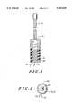
- FIG. 1illustrates a side view of the matched input antenna structure according to the present invention
- FIG. 2illustrates an end view of the matched input antenna structure according to the present invention
- FIG. 3illustrates a portable radio having a matched input antenna.
- two coils 10 and 20 of different dimensioncouple energy to an antenna element 30 according to the present invention.
- Coupling to the antenna element 30 using hot arm coil 10 and ground arm coil 20allows for a matched input at hot feedline 40 and ground feedline 50. This input allows the antenna of the present invention to operate more energy efficiently. By coupling with these two coils, more energy is transferred to and from the antenna element 30.
- the two coils of the hot arm coil 10 and the ground arm coil 20also improve the antenna pattern characteristics by eliminating the flow of induced currents on the housing of a radio below the two coils.
- the two coils 10 and 20cancel out the effects of energy traveling downward into a radio from the antenna element 30.
- a higher gain antennais thus achieved for better communications while current drain on the battery of a portable radio is reduced.
- Increased signal quality and sound quality communicationsare achieved with smaller batteries capable of providing longer operation before recharging.
- the two coils 10 and 20in various embodiments of the present invention, can be wrapped around a cardboard or plastic cylinder 60.
- the two coils 10 and 20are preferably flat copper microstrip conductors of roughly 0.05 millimeters (two thousandths of an inch) thick and roughly 1.778 millimeters (0.070 inches) wide.
- the two coils 10 and 20could be freestanding in space or encapsulated within a plastic molding.
- the cylinder 60preferably has as small as practical a diameter for compact realization and preferably has a diameter of less than one tenth of a wavelength of a signal to be transceived.
- a 8.128 millimeter (0.32 inches) diameter cylinder 60is preferred for a signal to be transmitted at 920 megahertz (MHz).
- the cylinder 60should at most have a diameter such that one turn of the coils has a circumference less than a wavelength of a signal to be transceived by the antenna.
- the circumference of the cylinder 60will be slightly smaller than the circumference of one turn of the coils.
- one of the two coils 10 and 20should be longer than the other coil. By providing one longer coil, an antenna input matched with the feedlines is achieved. This configuration has the added benefit of eliminating energy from being directed downward into a portable radio. Coils of a same length were found during experimentation to not achieve these objectives.
- the ground arm coil 20is preferably longer than the hot arm coil 10 by a ratio of 2.5 to 2.
- the cylinder 60has the diameter of approximately 8.128 millimeters (0.32 inches) and the hot arm coil has a coiled axial length of approximately 20.955 millimeters (0.825 inches) and the ground arm coil 20 has a coiled axial length of approximately 30.099 millimeters (1.185 inches) and the coils 10 and 20 are pitched at roughly a 15 degree angle.
- the hot arm coilhas approximately 3.25 turns and the ground arm coil has approximately 5.5 turns.
- the hot arm coil 10 and the ground arm coil 20are configurable for different operating frequencies to be transceived by adjusting the length of the two coils or the respective ratio of the number of turns. Assuming the cylinder 60 is perfectly cylindrical and the pitch of the coils remains constant, the number of turns will be directly proportional to the length of each coil. In this perfectly cylindrical cylinder, the pitched coils will be helical coils. However, should the pitch of the coils vary or the cylinder 60 instead be conical or otherwise shaped, the number of turns will not be directly proportional to the length of each coil. Depending on configuration and operating frequency to be transceived for an application, the respective lengths of the two coils should be experimentally determined to achieve matching and efficient coupling.
- the antenna elementis preferably coaxially disposed within the coils 10 and 20 for coupling thereto.
- the antenna element 30does not need to be coaxially disposed within the two coils. Coupling is also achieved when the antenna element is disposed in proximity to the coils such as next to the coils.
- Antenna element 30preferably consists of a single straight wire disposed within a plastic sheet or coating. The single straight wire of the antenna element 30 preferably extends downward adjacent to an entirety of the turns of the two coils 10 and 20. Because the antenna element 30 extends upward from a portable radio, only a portion such as the lower portion of the antenna element 30 preferably couples to the two coils 10 and 20.
- the hot arm coil 10 and the ground arm coil 20preferably are interleaved with one another as illustrated in FIG. 1.
- the hot arm coil 10 and the ground arm coil 20could preferably be offset such that the shorter coil is not completely, or at all, interleaved with the longer of the coils.
- FIG. 2illustrates an end view of the antenna structure where the antenna element 30 is coaxially surrounded by the hot arm coil 10 and the ground arm coil 20.
- the cylinder 60supports the two coils 10 and 20 with hot feedline 40 and ground feedline 50 at a lower portion thereof for connection to transmit or receive circuitry of a portable radio.
- FIG. 3illustrates a portable radio 70 such as a radiotelephone having increased antenna gain performance and energy efficiency using the hot arm coil 10 and the ground arm coil 20 in proximity to the antenna element 30.
- the hot feedline 40 and the ground feedline 50 of the two coils 10 and 20connect to radio transceiver circuitry 90 of the portable radio 70.
- the two coils 10 and 20are preferably disposed within a housing 80 of the portable radio 70 with the antenna element 30 extending therefrom.
- the antenna element 30can coaxially slide into and out of the housing of the portable radio 70 for storage. However, when the antenna element is retracted, the two coils 10 and 20 would couple to a different portion of the antenna element for operation.
- the hot arm coil 10 and ground arm coil 20may be placed coaxially with an antenna element 30 within a plastic housing of an antenna element. In such a configuration, the housing 80 of the antenna element could mechanically connect to the portable radio 70 at a pivot point.
- wire arrangementsmay be used to implement the two coils of the present invention. Further, these coils may be disposed in various alternate locations for coupling in proximity to an antenna element.
Landscapes
- Engineering & Computer Science (AREA)
- Computer Networks & Wireless Communication (AREA)
- Support Of Aerials (AREA)
- Details Of Aerials (AREA)
Abstract
Description
Claims (15)
Priority Applications (7)
| Application Number | Priority Date | Filing Date | Title |
|---|---|---|---|
| US08/508,939US5583520A (en) | 1995-07-28 | 1995-07-28 | Matched input antenna for a portable radio |
| SG1996010213ASG42424A1 (en) | 1995-07-28 | 1996-07-04 | Matched input antenna for a portable radio |
| FR9608457AFR2737345B1 (en) | 1995-07-28 | 1996-07-08 | ANTENNA WITH INPUT SUITABLE FOR PORTABLE RADIO |
| AU59443/96AAU707303B2 (en) | 1995-07-28 | 1996-07-11 | Matched input antenna for a portable radio |
| GB9615315AGB2303969B (en) | 1995-07-28 | 1996-07-22 | Matched input antenna for a portable radio |
| JP21541996AJP3532356B2 (en) | 1995-07-28 | 1996-07-26 | Matched input antenna for portable wireless devices |
| CN961108649ACN1065077C (en) | 1995-07-28 | 1996-07-26 | Matched input antenna of portable radio device |
Applications Claiming Priority (1)
| Application Number | Priority Date | Filing Date | Title |
|---|---|---|---|
| US08/508,939US5583520A (en) | 1995-07-28 | 1995-07-28 | Matched input antenna for a portable radio |
Publications (1)
| Publication Number | Publication Date |
|---|---|
| US5583520Atrue US5583520A (en) | 1996-12-10 |
Family
ID=24024678
Family Applications (1)
| Application Number | Title | Priority Date | Filing Date |
|---|---|---|---|
| US08/508,939Expired - LifetimeUS5583520A (en) | 1995-07-28 | 1995-07-28 | Matched input antenna for a portable radio |
Country Status (7)
| Country | Link |
|---|---|
| US (1) | US5583520A (en) |
| JP (1) | JP3532356B2 (en) |
| CN (1) | CN1065077C (en) |
| AU (1) | AU707303B2 (en) |
| FR (1) | FR2737345B1 (en) |
| GB (1) | GB2303969B (en) |
| SG (1) | SG42424A1 (en) |
Cited By (10)
| Publication number | Priority date | Publication date | Assignee | Title |
|---|---|---|---|---|
| FR2760132A1 (en)* | 1997-02-19 | 1998-08-28 | Motorola Inc | ANTENNA SUPPLIED BY SIDE-BY-SIDE COILS FOR A PORTABLE RADIO SET |
| US5945964A (en)* | 1997-02-19 | 1999-08-31 | Motorola, Inc. | Multi-band antenna structure for a portable radio |
| US6057807A (en)* | 1996-02-13 | 2000-05-02 | Allgon Ab | Dual band antenna means incorporating helical and elongated radiating structures |
| US6127979A (en)* | 1998-02-27 | 2000-10-03 | Motorola, Inc. | Antenna adapted to operate in a plurality of frequency bands |
| US6181286B1 (en) | 1998-07-22 | 2001-01-30 | Vistar Telecommunications Inc. | Integrated satellite/terrestrial antenna |
| US6275198B1 (en) | 2000-01-11 | 2001-08-14 | Motorola, Inc. | Wide band dual mode antenna |
| US20050184924A1 (en)* | 2004-02-20 | 2005-08-25 | Larry Fossett | Systems and methods that utilize an active stub/parasitic whip antenna to facilitate mobile communication |
| US20060290577A1 (en)* | 2005-06-09 | 2006-12-28 | Mete Ozkar | Retractable stubby antenna |
| US20080106485A1 (en)* | 2006-11-07 | 2008-05-08 | Wistron Neweb Corp. | Portable electronic device and antenna thereof |
| USD726631S1 (en)* | 2012-09-24 | 2015-04-14 | Checkers Industrial Products, Llc | Warning whip base and connector |
Citations (11)
| Publication number | Priority date | Publication date | Assignee | Title |
|---|---|---|---|---|
| US2709219A (en)* | 1951-11-20 | 1955-05-24 | Du Mont Allen B Lab Inc | High-frequency transformer and circuit |
| US3099010A (en)* | 1960-02-19 | 1963-07-23 | Columbia Products Co | High-q loading coil having plural interleaved paralleled windings in combination with axial antenna |
| US4121218A (en)* | 1977-08-03 | 1978-10-17 | Motorola, Inc. | Adjustable antenna arrangement for a portable radio |
| US4137534A (en)* | 1977-05-26 | 1979-01-30 | Goodnight Roy G | Vertical antenna with low angle of radiation |
| US4229743A (en)* | 1978-09-22 | 1980-10-21 | Shakespeare Company | Multiple band, multiple resonant frequency antenna |
| US4868576A (en)* | 1988-11-02 | 1989-09-19 | Motorola, Inc. | Extendable antenna for portable cellular telephones with ground radiator |
| US5057849A (en)* | 1988-12-20 | 1991-10-15 | Robert Bosch Gmbh | Rod antenna for multi-band television reception |
| US5083136A (en)* | 1989-11-16 | 1992-01-21 | Wells Donald H | Transmission line coupling device with closed impedance matching loop |
| US5179387A (en)* | 1989-03-10 | 1993-01-12 | Wells Donald H | Whip antenna operable without grounding |
| US5218372A (en)* | 1992-05-15 | 1993-06-08 | Cheng Chen Sheng | Wide band spherical antenna with improved impedance-matching circuit |
| US5420579A (en)* | 1990-10-29 | 1995-05-30 | Bio Medic Data Systems, Inc. | Antenna and driving circuit for transmitting and receiving signals to and from a passive transponder |
Family Cites Families (5)
| Publication number | Priority date | Publication date | Assignee | Title |
|---|---|---|---|---|
| GB2237449B (en)* | 1989-09-30 | 1994-03-30 | Hi Trak Systems Ltd | Transmitter and antenna |
| GB2253949B (en)* | 1991-03-16 | 1995-08-09 | Antenna Products Ltd | Radio Antennas |
| JPH06216630A (en)* | 1993-01-14 | 1994-08-05 | Nippon Antenna Kk | Expansion whip antenna |
| SE512062C2 (en)* | 1993-07-14 | 2000-01-17 | Ericsson Ge Mobile Communicat | Method and apparatus for improving the efficiency and bandwidth of an antenna on a portable equipment |
| KR0162160B1 (en)* | 1993-09-20 | 1998-12-01 | 조나단 피. 메이어 | Antenna arrangement for a wireless communication device |
- 1995
- 1995-07-28USUS08/508,939patent/US5583520A/ennot_activeExpired - Lifetime
- 1996
- 1996-07-04SGSG1996010213Apatent/SG42424A1/enunknown
- 1996-07-08FRFR9608457Apatent/FR2737345B1/ennot_activeExpired - Lifetime
- 1996-07-11AUAU59443/96Apatent/AU707303B2/ennot_activeCeased
- 1996-07-22GBGB9615315Apatent/GB2303969B/ennot_activeExpired - Fee Related
- 1996-07-26CNCN961108649Apatent/CN1065077C/ennot_activeExpired - Fee Related
- 1996-07-26JPJP21541996Apatent/JP3532356B2/ennot_activeExpired - Fee Related
Patent Citations (11)
| Publication number | Priority date | Publication date | Assignee | Title |
|---|---|---|---|---|
| US2709219A (en)* | 1951-11-20 | 1955-05-24 | Du Mont Allen B Lab Inc | High-frequency transformer and circuit |
| US3099010A (en)* | 1960-02-19 | 1963-07-23 | Columbia Products Co | High-q loading coil having plural interleaved paralleled windings in combination with axial antenna |
| US4137534A (en)* | 1977-05-26 | 1979-01-30 | Goodnight Roy G | Vertical antenna with low angle of radiation |
| US4121218A (en)* | 1977-08-03 | 1978-10-17 | Motorola, Inc. | Adjustable antenna arrangement for a portable radio |
| US4229743A (en)* | 1978-09-22 | 1980-10-21 | Shakespeare Company | Multiple band, multiple resonant frequency antenna |
| US4868576A (en)* | 1988-11-02 | 1989-09-19 | Motorola, Inc. | Extendable antenna for portable cellular telephones with ground radiator |
| US5057849A (en)* | 1988-12-20 | 1991-10-15 | Robert Bosch Gmbh | Rod antenna for multi-band television reception |
| US5179387A (en)* | 1989-03-10 | 1993-01-12 | Wells Donald H | Whip antenna operable without grounding |
| US5083136A (en)* | 1989-11-16 | 1992-01-21 | Wells Donald H | Transmission line coupling device with closed impedance matching loop |
| US5420579A (en)* | 1990-10-29 | 1995-05-30 | Bio Medic Data Systems, Inc. | Antenna and driving circuit for transmitting and receiving signals to and from a passive transponder |
| US5218372A (en)* | 1992-05-15 | 1993-06-08 | Cheng Chen Sheng | Wide band spherical antenna with improved impedance-matching circuit |
Non-Patent Citations (6)
| Title |
|---|
| Kraus, J. D., Antennas, 1988, 1950, pp. 323 325.* |
| Kraus, J. D., Antennas, 1988, 1950, pp. 323-325. |
| Nakano, H. et al., "Axial Mode Helical Antennas", IEEE Transactions on Antennas and Propagation, vol. AP-34, No. 9, Sep. 1986, pp. 1143-1148. |
| Nakano, H. et al., "Helical Antenna with Increased Power Gain", IEEE Antennas and Propagation Symposium, Dec. 8, 1984, pp. 417-420. |
| Nakano, H. et al., Axial Mode Helical Antennas , IEEE Transactions on Antennas and Propagation, vol. AP 34, No. 9, Sep. 1986, pp. 1143 1148.* |
| Nakano, H. et al., Helical Antenna with Increased Power Gain , IEEE Antennas and Propagation Symposium, Dec. 8, 1984, pp. 417 420.* |
Cited By (13)
| Publication number | Priority date | Publication date | Assignee | Title |
|---|---|---|---|---|
| US6057807A (en)* | 1996-02-13 | 2000-05-02 | Allgon Ab | Dual band antenna means incorporating helical and elongated radiating structures |
| CN1125499C (en)* | 1997-02-19 | 2003-10-22 | 摩托罗拉公司 | Multi-band antenna structure for portable radio |
| US5808586A (en)* | 1997-02-19 | 1998-09-15 | Motorola, Inc. | Side-by-side coil-fed antenna for a portable radio |
| US5945964A (en)* | 1997-02-19 | 1999-08-31 | Motorola, Inc. | Multi-band antenna structure for a portable radio |
| FR2760132A1 (en)* | 1997-02-19 | 1998-08-28 | Motorola Inc | ANTENNA SUPPLIED BY SIDE-BY-SIDE COILS FOR A PORTABLE RADIO SET |
| US6127979A (en)* | 1998-02-27 | 2000-10-03 | Motorola, Inc. | Antenna adapted to operate in a plurality of frequency bands |
| US6181286B1 (en) | 1998-07-22 | 2001-01-30 | Vistar Telecommunications Inc. | Integrated satellite/terrestrial antenna |
| US6275198B1 (en) | 2000-01-11 | 2001-08-14 | Motorola, Inc. | Wide band dual mode antenna |
| US20050184924A1 (en)* | 2004-02-20 | 2005-08-25 | Larry Fossett | Systems and methods that utilize an active stub/parasitic whip antenna to facilitate mobile communication |
| US20060290577A1 (en)* | 2005-06-09 | 2006-12-28 | Mete Ozkar | Retractable stubby antenna |
| US7224316B2 (en)* | 2005-06-09 | 2007-05-29 | Kyocera Wireless Corp. | Retractable stubby antenna |
| US20080106485A1 (en)* | 2006-11-07 | 2008-05-08 | Wistron Neweb Corp. | Portable electronic device and antenna thereof |
| USD726631S1 (en)* | 2012-09-24 | 2015-04-14 | Checkers Industrial Products, Llc | Warning whip base and connector |
Also Published As
| Publication number | Publication date |
|---|---|
| FR2737345B1 (en) | 1998-04-30 |
| CN1142125A (en) | 1997-02-05 |
| JP3532356B2 (en) | 2004-05-31 |
| GB9615315D0 (en) | 1996-09-04 |
| SG42424A1 (en) | 1997-08-15 |
| GB2303969B (en) | 1999-06-09 |
| AU5944396A (en) | 1997-02-06 |
| AU707303B2 (en) | 1999-07-08 |
| GB2303969A (en) | 1997-03-05 |
| FR2737345A1 (en) | 1997-01-31 |
| CN1065077C (en) | 2001-04-25 |
| JPH09186520A (en) | 1997-07-15 |
Similar Documents
| Publication | Publication Date | Title |
|---|---|---|
| US4730195A (en) | Shortened wideband decoupled sleeve dipole antenna | |
| US6646606B2 (en) | Double-action antenna | |
| US5600341A (en) | Dual function antenna structure and a portable radio having same | |
| US5945964A (en) | Multi-band antenna structure for a portable radio | |
| US6917334B2 (en) | Ultra-wide band meanderline fed monopole antenna | |
| JP3185233B2 (en) | Small antenna for portable radio | |
| US6278414B1 (en) | Bent-segment helical antenna | |
| US4800395A (en) | High efficiency helical antenna | |
| JP2003505963A (en) | Capacitively tuned broadband antenna structure | |
| IL134924A (en) | Dual-bank helix antenna with parasitic element | |
| JP2006187036A (en) | antenna | |
| US20060017620A1 (en) | Ultra-wide band meanderline fed monopole antenna | |
| WO1998005090A9 (en) | Bent-segment helical antenna | |
| US5583520A (en) | Matched input antenna for a portable radio | |
| JPH03236612A (en) | Helical antenna | |
| JP4125118B2 (en) | Wideband built-in antenna | |
| US5798736A (en) | Antenna system having a plurality of fundamental resonances | |
| US7113146B2 (en) | Broadband monopole | |
| US6518934B1 (en) | Parasitically driven dipole array | |
| WO1999054959A1 (en) | Antenna means and a handheld radio communication device including such means | |
| KR20010028316A (en) | Antenna for mobile communication terminal | |
| CN115775977A (en) | Miniaturized helical antenna | |
| HK1020805B (en) | Bent-segment helical antenna | |
| KR20000016682A (en) | Meander antenna device | |
| KR19990033683U (en) | Connecting member for extending antenna band width |
Legal Events
| Date | Code | Title | Description |
|---|---|---|---|
| AS | Assignment | Owner name:MOTOROLA, INC., ILLINOIS Free format text:ASSIGNMENT OF ASSIGNORS INTEREST;ASSIGNOR:THILL, KEVIN MICHAEL;REEL/FRAME:007612/0128 Effective date:19950728 | |
| STCF | Information on status: patent grant | Free format text:PATENTED CASE | |
| FPAY | Fee payment | Year of fee payment:4 | |
| FPAY | Fee payment | Year of fee payment:8 | |
| FPAY | Fee payment | Year of fee payment:12 | |
| AS | Assignment | Owner name:MOTOROLA MOBILITY, INC, ILLINOIS Free format text:ASSIGNMENT OF ASSIGNORS INTEREST;ASSIGNOR:MOTOROLA, INC;REEL/FRAME:025673/0558 Effective date:20100731 | |
| AS | Assignment | Owner name:WI-LAN INC., CANADA Free format text:ASSIGNMENT OF ASSIGNORS INTEREST;ASSIGNOR:MOTOROLA MOBILITY, INC.;REEL/FRAME:026916/0718 Effective date:20110127 | |
| AS | Assignment | Owner name:QUARTERHILL INC., CANADA Free format text:MERGER AND CHANGE OF NAME;ASSIGNORS:WI-LAN INC.;QUARTERHILL INC.;REEL/FRAME:042902/0932 Effective date:20170601 | |
| AS | Assignment | Owner name:WI-LAN INC., CANADA Free format text:ASSIGNMENT OF ASSIGNORS INTEREST;ASSIGNOR:QUARTERHILL INC.;REEL/FRAME:043167/0233 Effective date:20170601 |