US5583495A - Vehicle alarm system - Google Patents
Vehicle alarm systemDownload PDFInfo
- Publication number
- US5583495A US5583495AUS08/392,855US39285595AUS5583495AUS 5583495 AUS5583495 AUS 5583495AUS 39285595 AUS39285595 AUS 39285595AUS 5583495 AUS5583495 AUS 5583495A
- Authority
- US
- United States
- Prior art keywords
- vehicle
- signal
- ultrasound
- area
- driver
- Prior art date
- Legal status (The legal status is an assumption and is not a legal conclusion. Google has not performed a legal analysis and makes no representation as to the accuracy of the status listed.)
- Expired - Fee Related
Links
Images

Classifications
- G—PHYSICS
- G01—MEASURING; TESTING
- G01S—RADIO DIRECTION-FINDING; RADIO NAVIGATION; DETERMINING DISTANCE OR VELOCITY BY USE OF RADIO WAVES; LOCATING OR PRESENCE-DETECTING BY USE OF THE REFLECTION OR RERADIATION OF RADIO WAVES; ANALOGOUS ARRANGEMENTS USING OTHER WAVES
- G01S15/00—Systems using the reflection or reradiation of acoustic waves, e.g. sonar systems
- G01S15/88—Sonar systems specially adapted for specific applications
- G01S15/93—Sonar systems specially adapted for specific applications for anti-collision purposes
- G01S15/931—Sonar systems specially adapted for specific applications for anti-collision purposes of land vehicles
- B—PERFORMING OPERATIONS; TRANSPORTING
- B60—VEHICLES IN GENERAL
- B60Q—ARRANGEMENT OF SIGNALLING OR LIGHTING DEVICES, THE MOUNTING OR SUPPORTING THEREOF OR CIRCUITS THEREFOR, FOR VEHICLES IN GENERAL
- B60Q9/00—Arrangement or adaptation of signal devices not provided for in one of main groups B60Q1/00 - B60Q7/00, e.g. haptic signalling
- B60Q9/008—Arrangement or adaptation of signal devices not provided for in one of main groups B60Q1/00 - B60Q7/00, e.g. haptic signalling for anti-collision purposes
- Y—GENERAL TAGGING OF NEW TECHNOLOGICAL DEVELOPMENTS; GENERAL TAGGING OF CROSS-SECTIONAL TECHNOLOGIES SPANNING OVER SEVERAL SECTIONS OF THE IPC; TECHNICAL SUBJECTS COVERED BY FORMER USPC CROSS-REFERENCE ART COLLECTIONS [XRACs] AND DIGESTS
- Y10—TECHNICAL SUBJECTS COVERED BY FORMER USPC
- Y10S—TECHNICAL SUBJECTS COVERED BY FORMER USPC CROSS-REFERENCE ART COLLECTIONS [XRACs] AND DIGESTS
- Y10S367/00—Communications, electrical: acoustic wave systems and devices
- Y10S367/909—Collision avoidance
Definitions
- the present inventionrelates to the field of technical vision for objects detection, and, more particularly to systems for providing an alarm when a vehicle is present in the dead zone of driver's view (FIG. 1) at the left or right side of the vehicle, especially when the driver tries to move to one side or the other, as when changing lanes.
- an apparatus for the automatic detection of dangerous objects in the left and right sides of vehicle and in its back spacecomprising: ultrasound transmitters (4) activated by generators (6) with defined angle of radiation emitting ultrasound waves continuously or pulsed or modulated; ultrasound receivers (14) connected to an analog or digital analyzer for determination of intensity, speed of change, Doppler's frequency change and angle of fall of the received signal that depends on road situation; amplifiers (16), signal analyzer (18) includes time and frequency discriminators for speed and distance determination, received returned signal from amplifiers and standard signal from generator, control and signal from amplifiers and standard signal from generator, control and calculation unit with condition inputs like vehicle speed (10) and turn signal (12), commutation unit, alarm or display unit for communication with driver, communication to other vehicle systems that detects dangerous objects presence into the pre-defined area limited by lines of driver's direct view, borders of left and right adjacent lines of traffic and predetermined distance back and provides alarm or signalization to vehicle driver.
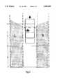
- FIG. 1contains basic drawing of driver's field of view where ⁇ 1 is a front view, ⁇ 2--view through left side mirror, ⁇ 3--view through right side mirror, ⁇ 4--panorama mirror view, ⁇ 1 and ⁇ 2 angles defining "dead area" of drivers view.
- R and Lare areas where detection of another vehicle is needed. Those areas includes two lines (in the left and right sides) limited by ⁇ 1 angle lines forward and same distance back from vehicle (about 10-15 meters). Dashed line shows dangerous object may occur in those areas.
- FIG. 2shows functional division of dangerous places on the left and right sides. Distance A is comparable with vehicle length. Distance B is additional length that dangerous object may arrive from.
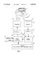
- FIG. 3presents a basic embodiment of the apparatus, according to the present invention which includes: radiation sources (4), radiation receivers (14), amplifiers (16), signal analyzer (18), control and calculation unit (8) with conditions inputs mm signal (12) and vehicle state of moving (10), terminals (20) like computer interface, alarm and/or signalization.
- FIG. 1presents the borders of vehicle driver's view, defined by direct angle ⁇ 1 in addition with back view throw the left side mirror ⁇ 2, back view through right side mirror ⁇ 3 and back view through panorama mirror ⁇ 4.
- Non detected vehiclemay appear in dead area.
- Danger stateoccurs when driver tries to move to the left or right path of the road for overcoming preceding low speed vehicle or any object on the left or right.
- An accidentmay occur.
- For prevention of accident drivermust have alarm when another vehicle is moving in the dead area or comes near for overcame his own vehicle.
- An object of the present inventionis to provide appropriate solutions for detection of a vehicle appeared in the dead field of drivers view or in every place in the right or left side and in questionable areas back of them.
- Proposed problem solutionbased on ultrasound location of the dangerous area R and L defined on FIGS. 1 and 2.
- the ultrasound waves emitted from transmitters 4 to the dangerous areaare reflected back from the overtake or moving parallel vehicle 2 and receiver 14.
- Ultrasound signalsare emitted by transmitters, for, may be individualize continuous or pulsed or modulated for each individual vehicle, and thereby preventing interference between ultrasound vehicle detection signals emitted and received by adjacent vehicles.
- Amplified by amplifiers 16 signal goes to signal analyzer 18may be either an analog or digital analyzer for place determination of place and speed of vehicle in this area.
- Control and calculation unit 8takes into account a number of useful signals like its own speed and state of turn signal.
- the proposed systemis preferably activated if two conditions are presented: vehicle moves (speed signal 10) and driver intends to change lane left and right (ram signal 12), but may also be activated continuously without regard to the turn signal 12 being activated.
- vehicle movesspeed signal 10
- driverintends to change lane left and right
- ram signal 12ram signal 12
- the vehicleWhen the vehicle is stationary it may be desirable to increase the zone of hazard in order to take into account the greater differential speed between the stationary vehicle and the nearby moving vehicles.
- In the terminals set computer interfaceis available for communication with more complete and complicated systems of vehicle electronics. Other terminals are different systems of alarming and signalization.
- a non wire communication channelmay be provided between the control and calculations unit and the alarm or display unit.
- the apparatusactivates if only two conditions are present: speed of vehicle is not equal to zero--vehicle moves: turn signal is turned on indicating that the driver intends to move left or right.
- Transmitters and receiversmay be installed on the external left and/or right side of the vehicle, or on the rearview mirror, or on the external top part of the vehicle. While the invention has been described with respect to a limited number of embodiments, it will be appreciated that many variations, modifications and other applications of the invention may be made.
Landscapes
- Engineering & Computer Science (AREA)
- Radar, Positioning & Navigation (AREA)
- Remote Sensing (AREA)
- Physics & Mathematics (AREA)
- Acoustics & Sound (AREA)
- Computer Networks & Wireless Communication (AREA)
- General Physics & Mathematics (AREA)
- Human Computer Interaction (AREA)
- Mechanical Engineering (AREA)
- Measurement Of Velocity Or Position Using Acoustic Or Ultrasonic Waves (AREA)
- Traffic Control Systems (AREA)
Abstract
Description
The present invention relates to the field of technical vision for objects detection, and, more particularly to systems for providing an alarm when a vehicle is present in the dead zone of driver's view (FIG. 1) at the left or right side of the vehicle, especially when the driver tries to move to one side or the other, as when changing lanes.
According to the present invention, there is provided an apparatus for the automatic detection of dangerous objects in the left and right sides of vehicle and in its back space comprising: ultrasound transmitters (4) activated by generators (6) with defined angle of radiation emitting ultrasound waves continuously or pulsed or modulated; ultrasound receivers (14) connected to an analog or digital analyzer for determination of intensity, speed of change, Doppler's frequency change and angle of fall of the received signal that depends on road situation; amplifiers (16), signal analyzer (18) includes time and frequency discriminators for speed and distance determination, received returned signal from amplifiers and standard signal from generator, control and signal from amplifiers and standard signal from generator, control and calculation unit with condition inputs like vehicle speed (10) and turn signal (12), commutation unit, alarm or display unit for communication with driver, communication to other vehicle systems that detects dangerous objects presence into the pre-defined area limited by lines of driver's direct view, borders of left and right adjacent lines of traffic and predetermined distance back and provides alarm or signalization to vehicle driver.
The invention is herein described, by way of example only, with reference to the accompanying drawings, wherein:
FIG. 1 contains basic drawing of driver's field of view where α1 is a front view, α2--view through left side mirror, α3--view through right side mirror, α4--panorama mirror view, β1 and β2 angles defining "dead area" of drivers view. R and L are areas where detection of another vehicle is needed. Those areas includes two lines (in the left and right sides) limited by α1 angle lines forward and same distance back from vehicle (about 10-15 meters). Dashed line shows dangerous object may occur in those areas.
FIG. 2 shows functional division of dangerous places on the left and right sides. Distance A is comparable with vehicle length. Distance B is additional length that dangerous object may arrive from.
FIG. 3 presents a basic embodiment of the apparatus, according to the present invention which includes: radiation sources (4), radiation receivers (14), amplifiers (16), signal analyzer (18), control and calculation unit (8) with conditions inputs mm signal (12) and vehicle state of moving (10), terminals (20) like computer interface, alarm and/or signalization.
FIG. 1 presents the borders of vehicle driver's view, defined by direct angle α1 in addition with back view throw the left side mirror α2, back view through right side mirror α3 and back view through panorama mirror α4. There remains blind spot dead area open space in angle β1 in left β2 in right side of drawing vehicle. Non detected vehicle may appear in dead area. Danger state occurs when driver tries to move to the left or right path of the road for overcoming preceding low speed vehicle or any object on the left or right. An accident may occur. For prevention of accident driver must have alarm when another vehicle is moving in the dead area or comes near for overcame his own vehicle.
An object of the present invention is to provide appropriate solutions for detection of a vehicle appeared in the dead field of drivers view or in every place in the right or left side and in questionable areas back of them. Proposed problem solution based on ultrasound location of the dangerous area R and L defined on FIGS. 1 and 2. The ultrasound waves emitted from transmitters 4 to the dangerous area are reflected back from the overtake or moving parallel vehicle 2 andreceiver 14. Ultrasound signals are emitted by transmitters, for, may be individualize continuous or pulsed or modulated for each individual vehicle, and thereby preventing interference between ultrasound vehicle detection signals emitted and received by adjacent vehicles. Amplified byamplifiers 16 signal goes tosignal analyzer 18 may be either an analog or digital analyzer for place determination of place and speed of vehicle in this area. Control andcalculation unit 8 takes into account a number of useful signals like its own speed and state of turn signal. The proposed system is preferably activated if two conditions are presented: vehicle moves (speed signal 10) and driver intends to change lane left and right (ram signal 12), but may also be activated continuously without regard to theturn signal 12 being activated. When the vehicle is stationary it may be desirable to increase the zone of hazard in order to take into account the greater differential speed between the stationary vehicle and the nearby moving vehicles. In the terminals set computer interface is available for communication with more complete and complicated systems of vehicle electronics. Other terminals are different systems of alarming and signalization. A non wire communication channel may be provided between the control and calculations unit and the alarm or display unit.
In a preferred embodiment, the apparatus activates if only two conditions are present: speed of vehicle is not equal to zero--vehicle moves: turn signal is turned on indicating that the driver intends to move left or right.
There is a difference among distances A and B. An object in areas R and L into the region A is always dangerous. Vehicle in region B is dangerous only if distance among the two vehicles decreases. An apparatus actions defined for those two regions is different.
For regions L and R on distance A alarm or signalization will be activated only if an overcoming vehicle will be detected in those areas.
For regions L and R on distance B alarm or signalization will be activated in case when the speed of the detected vehicle is more than the detector's carrier speed. The negative or positive difference of speed can be defined by use of Doppler Effect.
Transmitters and receivers may be installed on the external left and/or right side of the vehicle, or on the rearview mirror, or on the external top part of the vehicle. While the invention has been described with respect to a limited number of embodiments, it will be appreciated that many variations, modifications and other applications of the invention may be made.
Claims (6)
1. An apparatus for the automatic detection of dangerous objects in the left and right sides of vehicle and in its back space comprising:
(a) generators, capable of generating individualized signals;
(b) ultrasound transmitters activated by generators for emitting a continuously or pulsed or modulated ultrasound signal with defined angle of radiation;
(c) ultrasound receivers for receiving a signal depending on the road situation connected to an analog or digital analyzer for determination of intensity, speed of change, Doppler's frequency change and angle of fall of said received signal that depends on road situation;
(d) amplifiers, for amplifying said received signal depending on road situation;
(e) signal analyzer includes time and frequency discriminators for speed and distance determination, received returned signal from amplifiers and standard signal from generator;
(f) control and calculation unit with condition inputs including vehicle speed and turn signal;
(g) communication terminals, including alarm or display unit for communication with a driver, said alarm or display unit providing alarm or signalization to said driver in the event of the dangerous objects presence in a predefined area, wherein said pre-defined area is a first area that is limited by lines of said driver's direct view, a second area of the borders of left and right adjacent lines of traffic and a third area of a predetermined distance back from the vehicle, said predefined area including dead area open space defined by angles β1 and β2;
(h) individualizing of continuous or pulsed or modulated ultrasound signals for each individual vehicle blind spot detector, thereby preventing interference between ultrasound vehicle detection signals emitted and received by adjacent vehicles.
2. An apparatus according to claim 1 wherein said emitted and received signal includes a sound or ultrasound signal.
3. An apparatus according to claim 1, wherein said ultrasound transmitters and receivers are installed on the external left and/or right side of the vehicle which has rear-view mirrors, adjacent to said rear-view mirrors.
4. An apparatus according to claim 1 wherein said ultrasound transmitters and receivers are installed on the external top part of the vehicle.
5. An apparatus according to claim 1 further comprising a non wire communication channel between said control and calculations unit and said alarm or display unit.
6. An apparatus according to claim 1, wherein said communications terminals further include a computer interface for communication with more complete and complicated systems of vehicle electronics.
Priority Applications (1)
| Application Number | Priority Date | Filing Date | Title |
|---|---|---|---|
| US08/392,855US5583495A (en) | 1992-09-02 | 1993-09-01 | Vehicle alarm system |
Applications Claiming Priority (4)
| Application Number | Priority Date | Filing Date | Title |
|---|---|---|---|
| IL103024AIL103024A0 (en) | 1992-09-02 | 1992-09-02 | Vehicle alarm system for prevention of road accidents |
| IL103024 | 1992-09-02 | ||
| US08/392,855US5583495A (en) | 1992-09-02 | 1993-09-01 | Vehicle alarm system |
| PCT/US1993/008193WO1994005525A1 (en) | 1992-09-02 | 1993-09-01 | Vehicle alarm system |
Publications (1)
| Publication Number | Publication Date |
|---|---|
| US5583495Atrue US5583495A (en) | 1996-12-10 |
Family
ID=26322500
Family Applications (1)
| Application Number | Title | Priority Date | Filing Date |
|---|---|---|---|
| US08/392,855Expired - Fee RelatedUS5583495A (en) | 1992-09-02 | 1993-09-01 | Vehicle alarm system |
Country Status (1)
| Country | Link |
|---|---|
| US (1) | US5583495A (en) |
Cited By (40)
| Publication number | Priority date | Publication date | Assignee | Title |
|---|---|---|---|---|
| US5709281A (en)* | 1995-09-14 | 1998-01-20 | Trw Inc. | Method and apparatus for adjusting steering feel |
| US5712640A (en)* | 1994-11-28 | 1998-01-27 | Honda Giken Kogyo Kabushiki Kaisha | Radar module for radar system on motor vehicle |
| US5959555A (en)* | 1996-08-23 | 1999-09-28 | Furuta; Yoshihisa | Apparatus for checking blind spots of vehicle |
| US5963127A (en)* | 1996-10-07 | 1999-10-05 | Mekra Lang Gmbh & Co. Kg | Control equipment for difficult to see or blind spot areas around vehicles, and related method |
| US6348858B2 (en)* | 1999-01-08 | 2002-02-19 | Volkswagen Ag | Method and device for surveillance of the rearward observation area of motor vehicles |
| US6363326B1 (en)* | 1997-11-05 | 2002-03-26 | Robert Lawrence Scully | Method and apparatus for detecting an object on a side of or backwards of a vehicle |
| US6369702B1 (en) | 1999-02-05 | 2002-04-09 | Lang-Mekra North America, Llc | Rearview mirror with safety catch |
| US20020044082A1 (en)* | 2000-08-16 | 2002-04-18 | Woodington Walter Gordon | Radar detection method and apparatus |
| US20020049539A1 (en)* | 2000-09-08 | 2002-04-25 | Russell Mark E. | Path prediction system and method |
| US6388565B1 (en)* | 1999-05-08 | 2002-05-14 | Daimlerchrysler Ag | Guidance system for assisting lane change of a motor vehicle |
| US20020067287A1 (en)* | 2000-08-16 | 2002-06-06 | Delcheccolo Michael Joseph | Near object detection system |
| US20020072843A1 (en)* | 2000-08-16 | 2002-06-13 | Russell Mark E. | Safe distance algorithm for adaptive cruise control |
| US6416191B1 (en) | 1999-03-23 | 2002-07-09 | Lang-Mekra North America, Llc | Double walled carrier plate and related mirror assembly |
| US20020163478A1 (en)* | 2000-08-16 | 2002-11-07 | Pleva Joseph S. | Switched beam antenna architecture |
| US20030004633A1 (en)* | 2001-03-14 | 2003-01-02 | Russell Mark E. | Safe distance algorithm for adaptive cruise control |
| US6611227B1 (en) | 2002-08-08 | 2003-08-26 | Raytheon Company | Automotive side object detection sensor blockage detection system and related techniques |
| US20030210172A1 (en)* | 2000-08-16 | 2003-11-13 | Pleva Joseph S. | Technique for changing a range gate and radar coverage |
| US20030210182A1 (en)* | 2000-08-16 | 2003-11-13 | Hanson James T. | Video amplifier for a radar receiver |
| US6657581B1 (en)* | 2000-08-16 | 2003-12-02 | Raytheon Company | Automotive lane changing aid indicator |
| US6674394B1 (en)* | 2003-03-28 | 2004-01-06 | Visteon Global Technologies, Inc. | Method for determining object location from side-looking sensor data |
| US6734807B2 (en)* | 1999-04-01 | 2004-05-11 | Lear Automotive Dearborn, Inc. | Polarametric blind spot detector with steerable beam |
| US6803858B2 (en) | 2002-04-29 | 2004-10-12 | Sandra Whitted | Blind spot alert system |
| US20050128060A1 (en)* | 2003-11-19 | 2005-06-16 | Mark Rennick | Universally usable object detection system and method |
| US6970142B1 (en) | 2001-08-16 | 2005-11-29 | Raytheon Company | Antenna configurations for reduced radar complexity |
| US6975932B2 (en)* | 1997-08-01 | 2005-12-13 | American Calcar Inc. | Technique for maintaining a separation between a vehicle and a detectable object |
| US20050275514A1 (en)* | 2004-05-26 | 2005-12-15 | Roberts Kristie L | Collision detection and warning system for automobiles |
| US6995730B2 (en) | 2001-08-16 | 2006-02-07 | Raytheon Company | Antenna configurations for reduced radar complexity |
| US6995687B2 (en) | 2001-06-22 | 2006-02-07 | Lang-Mekra North America, Llc | Parking aid for use in a motor vehicle |
| US7009498B2 (en) | 2001-04-03 | 2006-03-07 | Lang-Mekra North America, Llc | Mirror arrangement for motor vehicles |
| US7079017B2 (en) | 2001-04-23 | 2006-07-18 | Lang-Mekra North America, Llc | Warning device in motor vehicles |
| US7183995B2 (en) | 2001-08-16 | 2007-02-27 | Raytheon Company | Antenna configurations for reduced radar complexity |
| DE102006004866A1 (en)* | 2006-02-02 | 2007-08-16 | Siemens Ag | Driver assistance system for a vehicle and method for operating a vehicle |
| US7729856B2 (en) | 2003-05-22 | 2010-06-01 | Robert Bosch Gmbh | Method and device for detecting objects in the surroundings of a vehicle |
| US20110018698A1 (en)* | 2009-07-27 | 2011-01-27 | Charlton Rodriguez | Electrical car sensor for blind spots |
| US7973701B2 (en) | 2008-03-31 | 2011-07-05 | Valeo Radar Systems, Inc. | Automotive radar sensor blockage detection system and related techniques |
| US20130218398A1 (en)* | 2012-02-22 | 2013-08-22 | GM Global Technology Operations LLC | Method for determining object sensor misalignment |
| USD733722S1 (en)* | 2012-12-27 | 2015-07-07 | Nissan Jidosha Kabushiki Kaisha | Display screen or portion thereof with graphical user interface |
| US9472023B2 (en)* | 2014-10-06 | 2016-10-18 | Toyota Jidosha Kabushiki Kaisha | Safety system for augmenting roadway objects on a heads-up display |
| CN111355925A (en)* | 2018-12-21 | 2020-06-30 | 丰田自动车株式会社 | Control device, vehicle, image display system, and image display method |
| US20220108602A1 (en)* | 2020-10-01 | 2022-04-07 | Magna Electronics Inc. | Vehicular communication system with turn signal identification |
Citations (5)
| Publication number | Priority date | Publication date | Assignee | Title |
|---|---|---|---|---|
| US4028662A (en)* | 1976-05-24 | 1977-06-07 | Raymond Donald Young | Passing vehicle signalling apparatus |
| GB2076197A (en)* | 1980-05-07 | 1981-11-25 | Ho Chi Chen | Warning equipment in and for a road vehicle |
| US4694296A (en)* | 1984-03-13 | 1987-09-15 | Nippon Soken, Inc. | Vehicle approach sensing apparatus |
| JPH0424800A (en)* | 1990-05-15 | 1992-01-28 | Mazda Motor Corp | Rear monitoring device for vehicle |
| US5235316A (en)* | 1991-12-20 | 1993-08-10 | Qualizza Gregory K | Vehicle collision avoidance system |
- 1993
- 1993-09-01USUS08/392,855patent/US5583495A/ennot_activeExpired - Fee Related
Patent Citations (5)
| Publication number | Priority date | Publication date | Assignee | Title |
|---|---|---|---|---|
| US4028662A (en)* | 1976-05-24 | 1977-06-07 | Raymond Donald Young | Passing vehicle signalling apparatus |
| GB2076197A (en)* | 1980-05-07 | 1981-11-25 | Ho Chi Chen | Warning equipment in and for a road vehicle |
| US4694296A (en)* | 1984-03-13 | 1987-09-15 | Nippon Soken, Inc. | Vehicle approach sensing apparatus |
| JPH0424800A (en)* | 1990-05-15 | 1992-01-28 | Mazda Motor Corp | Rear monitoring device for vehicle |
| US5235316A (en)* | 1991-12-20 | 1993-08-10 | Qualizza Gregory K | Vehicle collision avoidance system |
Cited By (65)
| Publication number | Priority date | Publication date | Assignee | Title |
|---|---|---|---|---|
| US5712640A (en)* | 1994-11-28 | 1998-01-27 | Honda Giken Kogyo Kabushiki Kaisha | Radar module for radar system on motor vehicle |
| US5709281A (en)* | 1995-09-14 | 1998-01-20 | Trw Inc. | Method and apparatus for adjusting steering feel |
| US5959555A (en)* | 1996-08-23 | 1999-09-28 | Furuta; Yoshihisa | Apparatus for checking blind spots of vehicle |
| US5963127A (en)* | 1996-10-07 | 1999-10-05 | Mekra Lang Gmbh & Co. Kg | Control equipment for difficult to see or blind spot areas around vehicles, and related method |
| US7512495B2 (en) | 1997-08-01 | 2009-03-31 | American Calcar, Inc. | Centralized control and management system for automobiles |
| US6975932B2 (en)* | 1997-08-01 | 2005-12-13 | American Calcar Inc. | Technique for maintaining a separation between a vehicle and a detectable object |
| US7162370B2 (en) | 1997-08-01 | 2007-01-09 | American Calcar Inc. | Centralized control and management system for automobiles |
| US6363326B1 (en)* | 1997-11-05 | 2002-03-26 | Robert Lawrence Scully | Method and apparatus for detecting an object on a side of or backwards of a vehicle |
| US6348858B2 (en)* | 1999-01-08 | 2002-02-19 | Volkswagen Ag | Method and device for surveillance of the rearward observation area of motor vehicles |
| US6369702B1 (en) | 1999-02-05 | 2002-04-09 | Lang-Mekra North America, Llc | Rearview mirror with safety catch |
| EP1026036A3 (en)* | 1999-02-05 | 2002-07-03 | MEKRA Lang GmbH & Co. KG | Rear view mirror, in particular exterior mirror for vehicles |
| US6416191B1 (en) | 1999-03-23 | 2002-07-09 | Lang-Mekra North America, Llc | Double walled carrier plate and related mirror assembly |
| US6734807B2 (en)* | 1999-04-01 | 2004-05-11 | Lear Automotive Dearborn, Inc. | Polarametric blind spot detector with steerable beam |
| US6388565B1 (en)* | 1999-05-08 | 2002-05-14 | Daimlerchrysler Ag | Guidance system for assisting lane change of a motor vehicle |
| US6784828B2 (en) | 2000-08-16 | 2004-08-31 | Raytheon Company | Near object detection system |
| US6864831B2 (en) | 2000-08-16 | 2005-03-08 | Raytheon Company | Radar detection method and apparatus |
| US20020044082A1 (en)* | 2000-08-16 | 2002-04-18 | Woodington Walter Gordon | Radar detection method and apparatus |
| US20020067287A1 (en)* | 2000-08-16 | 2002-06-06 | Delcheccolo Michael Joseph | Near object detection system |
| US20030001772A1 (en)* | 2000-08-16 | 2003-01-02 | Woodington Walter Gordon | Radar detection method and apparatus |
| US6577269B2 (en) | 2000-08-16 | 2003-06-10 | Raytheon Company | Radar detection method and apparatus |
| US7071868B2 (en) | 2000-08-16 | 2006-07-04 | Raytheon Company | Radar detection method and apparatus |
| US6642908B2 (en) | 2000-08-16 | 2003-11-04 | Raytheon Company | Switched beam antenna architecture |
| US20030210172A1 (en)* | 2000-08-16 | 2003-11-13 | Pleva Joseph S. | Technique for changing a range gate and radar coverage |
| US20030210182A1 (en)* | 2000-08-16 | 2003-11-13 | Hanson James T. | Video amplifier for a radar receiver |
| US6657581B1 (en)* | 2000-08-16 | 2003-12-02 | Raytheon Company | Automotive lane changing aid indicator |
| US6670910B2 (en) | 2000-08-16 | 2003-12-30 | Raytheon Company | Near object detection system |
| US20020163478A1 (en)* | 2000-08-16 | 2002-11-07 | Pleva Joseph S. | Switched beam antenna architecture |
| US6977609B2 (en) | 2000-08-16 | 2005-12-20 | Raytheon Company | Technique for changing a range gate and radar coverage |
| US6683557B2 (en) | 2000-08-16 | 2004-01-27 | Raytheon Company | Technique for changing a range gate and radar for coverage |
| US6707419B2 (en) | 2000-08-16 | 2004-03-16 | Raytheon Company | Radar transmitter circuitry and techniques |
| US20020072843A1 (en)* | 2000-08-16 | 2002-06-13 | Russell Mark E. | Safe distance algorithm for adaptive cruise control |
| US20020147534A1 (en)* | 2000-08-16 | 2002-10-10 | Delcheccolo Michael Joseph | Near object detection system |
| US20020075178A1 (en)* | 2000-08-16 | 2002-06-20 | Woodington Walter Gordon | Radar transmitter circuitry and techniques |
| US6903679B2 (en) | 2000-08-16 | 2005-06-07 | Raytheon Company | Video amplifier for a radar receiver |
| US6675094B2 (en) | 2000-09-08 | 2004-01-06 | Raytheon Company | Path prediction system and method |
| US20020049539A1 (en)* | 2000-09-08 | 2002-04-25 | Russell Mark E. | Path prediction system and method |
| US6708100B2 (en) | 2001-03-14 | 2004-03-16 | Raytheon Company | Safe distance algorithm for adaptive cruise control |
| US20030004633A1 (en)* | 2001-03-14 | 2003-01-02 | Russell Mark E. | Safe distance algorithm for adaptive cruise control |
| US7009498B2 (en) | 2001-04-03 | 2006-03-07 | Lang-Mekra North America, Llc | Mirror arrangement for motor vehicles |
| US7079017B2 (en) | 2001-04-23 | 2006-07-18 | Lang-Mekra North America, Llc | Warning device in motor vehicles |
| US6995687B2 (en) | 2001-06-22 | 2006-02-07 | Lang-Mekra North America, Llc | Parking aid for use in a motor vehicle |
| US6995730B2 (en) | 2001-08-16 | 2006-02-07 | Raytheon Company | Antenna configurations for reduced radar complexity |
| US6970142B1 (en) | 2001-08-16 | 2005-11-29 | Raytheon Company | Antenna configurations for reduced radar complexity |
| US7183995B2 (en) | 2001-08-16 | 2007-02-27 | Raytheon Company | Antenna configurations for reduced radar complexity |
| US6803858B2 (en) | 2002-04-29 | 2004-10-12 | Sandra Whitted | Blind spot alert system |
| US6611227B1 (en) | 2002-08-08 | 2003-08-26 | Raytheon Company | Automotive side object detection sensor blockage detection system and related techniques |
| US6674394B1 (en)* | 2003-03-28 | 2004-01-06 | Visteon Global Technologies, Inc. | Method for determining object location from side-looking sensor data |
| US7729856B2 (en) | 2003-05-22 | 2010-06-01 | Robert Bosch Gmbh | Method and device for detecting objects in the surroundings of a vehicle |
| US20050128060A1 (en)* | 2003-11-19 | 2005-06-16 | Mark Rennick | Universally usable object detection system and method |
| US20050275514A1 (en)* | 2004-05-26 | 2005-12-15 | Roberts Kristie L | Collision detection and warning system for automobiles |
| US7046128B2 (en) | 2004-05-26 | 2006-05-16 | Roberts Kristie L | Collision detection and warning system for automobiles |
| DE102006004866A1 (en)* | 2006-02-02 | 2007-08-16 | Siemens Ag | Driver assistance system for a vehicle and method for operating a vehicle |
| DE102006004866B4 (en)* | 2006-02-02 | 2011-12-08 | Continental Automotive Gmbh | Driver assistance system for a vehicle and method for operating a vehicle |
| US7973701B2 (en) | 2008-03-31 | 2011-07-05 | Valeo Radar Systems, Inc. | Automotive radar sensor blockage detection system and related techniques |
| US20110018698A1 (en)* | 2009-07-27 | 2011-01-27 | Charlton Rodriguez | Electrical car sensor for blind spots |
| US20130218398A1 (en)* | 2012-02-22 | 2013-08-22 | GM Global Technology Operations LLC | Method for determining object sensor misalignment |
| US8930063B2 (en)* | 2012-02-22 | 2015-01-06 | GM Global Technology Operations LLC | Method for determining object sensor misalignment |
| USD733722S1 (en)* | 2012-12-27 | 2015-07-07 | Nissan Jidosha Kabushiki Kaisha | Display screen or portion thereof with graphical user interface |
| US9472023B2 (en)* | 2014-10-06 | 2016-10-18 | Toyota Jidosha Kabushiki Kaisha | Safety system for augmenting roadway objects on a heads-up display |
| CN106796755A (en)* | 2014-10-06 | 2017-05-31 | 丰田自动车株式会社 | Enhanced safety system for road objects on heads-up display |
| CN106796755B (en)* | 2014-10-06 | 2019-07-05 | 丰田自动车株式会社 | Enhanced safety system for pavement objects on HUD |
| CN111355925A (en)* | 2018-12-21 | 2020-06-30 | 丰田自动车株式会社 | Control device, vehicle, image display system, and image display method |
| CN111355925B (en)* | 2018-12-21 | 2021-09-14 | 丰田自动车株式会社 | Control device, vehicle, image display system, and image display method |
| US20220108602A1 (en)* | 2020-10-01 | 2022-04-07 | Magna Electronics Inc. | Vehicular communication system with turn signal identification |
| US11749105B2 (en)* | 2020-10-01 | 2023-09-05 | Magna Electronics Inc. | Vehicular communication system with turn signal identification |
Similar Documents
| Publication | Publication Date | Title |
|---|---|---|
| US5583495A (en) | Vehicle alarm system | |
| EP1261957B1 (en) | Blind spot detector | |
| EP0974851B1 (en) | Method and apparatus for rejecting rain clutter in a radar system | |
| AU2002211733B2 (en) | Collision avoidance method and system | |
| US5777563A (en) | Method and assembly for object detection by a vehicle | |
| US6281786B1 (en) | Obstacle detection system for a vehicle | |
| US5767793A (en) | Compact vehicle based rear and side obstacle detection system including multiple antennae | |
| US5339075A (en) | Vehicular collision avoidance apparatus | |
| US6433679B1 (en) | Warning device for an automobile | |
| KR950703158A (en) | SMART BLIND SPOT SENSOR | |
| US5001777A (en) | Police radar detector | |
| US11834064B2 (en) | Method and system for detecting non-visible vehicles | |
| EP0659128A1 (en) | Vehicle alarm system | |
| JP4179577B2 (en) | Radar wave relay device for approach notification | |
| US6832137B2 (en) | Leaky cable based method and system for automotive parking aid, reversing aid, and pre-collision sensing | |
| JPH04299800A (en) | Microwave apparatus for preventing collision between vehicles and data transmitting method therefor | |
| CN210617998U (en) | Blind area detection equipment for freight transport and passenger transport vehicles | |
| EP1040462B1 (en) | System for avoiding collision of vehicles in low visibility conditions | |
| KR100483275B1 (en) | Radar system for vehicle | |
| CN111824011A (en) | Alarm method for rear vehicle approaching | |
| JPH07209419A (en) | Obstacle detection device | |
| CA2120638A1 (en) | Blind spot warning device | |
| JP3202865B2 (en) | Parent-child station mutual danger recognition type ultrasonic transceiver | |
| JPH06231394A (en) | Inter-vehicle distance alarm device | |
| GB2265062A (en) | Vehicle collision warning system |
Legal Events
| Date | Code | Title | Description |
|---|---|---|---|
| REMI | Maintenance fee reminder mailed | ||
| LAPS | Lapse for failure to pay maintenance fees | ||
| FP | Lapsed due to failure to pay maintenance fee | Effective date:20001210 | |
| STCH | Information on status: patent discontinuation | Free format text:PATENT EXPIRED DUE TO NONPAYMENT OF MAINTENANCE FEES UNDER 37 CFR 1.362 |