US5582754A - Heated tray - Google Patents
Heated trayDownload PDFInfo
- Publication number
- US5582754A US5582754AUS08/374,895US37489595AUS5582754AUS 5582754 AUS5582754 AUS 5582754AUS 37489595 AUS37489595 AUS 37489595AUS 5582754 AUS5582754 AUS 5582754A
- Authority
- US
- United States
- Prior art keywords
- conductive polymer
- tray
- electrically conductive
- heated tray
- heated
- Prior art date
- Legal status (The legal status is an assumption and is not a legal conclusion. Google has not performed a legal analysis and makes no representation as to the accuracy of the status listed.)
- Expired - Lifetime
Links
- 229920001940conductive polymerPolymers0.000claimsabstractdescription104
- 239000007788liquidSubstances0.000claimsabstractdescription50
- 229920000642polymerPolymers0.000claimsdescription38
- 238000010438heat treatmentMethods0.000claimsdescription20
- 229920001903high density polyethylenePolymers0.000claimsdescription16
- 239000004700high-density polyethyleneSubstances0.000claimsdescription16
- 239000006229carbon blackSubstances0.000claimsdescription9
- 239000004698PolyethyleneSubstances0.000claimsdescription7
- 239000004734Polyphenylene sulfideSubstances0.000claimsdescription7
- UCKMPCXJQFINFW-UHFFFAOYSA-NSulphideChemical compound[S-2]UCKMPCXJQFINFW-UHFFFAOYSA-N0.000claimsdescription7
- 238000000465mouldingMethods0.000claimsdescription7
- 229920000515polycarbonatePolymers0.000claimsdescription7
- 239000004417polycarbonateSubstances0.000claimsdescription7
- -1polyethylenePolymers0.000claimsdescription7
- 229920000573polyethylenePolymers0.000claimsdescription7
- 229920000069polyphenylene sulfidePolymers0.000claimsdescription7
- 230000000750progressive effectEffects0.000claimsdescription7
- 230000037452primingEffects0.000claims1
- 239000002861polymer materialSubstances0.000description29
- 238000000034methodMethods0.000description10
- 239000000463materialSubstances0.000description9
- 229920001169thermoplasticPolymers0.000description8
- 239000004416thermosoftening plasticSubstances0.000description8
- 230000008901benefitEffects0.000description6
- 210000003811fingerAnatomy0.000description4
- 230000007246mechanismEffects0.000description4
- 230000008018meltingEffects0.000description4
- 238000002844meltingMethods0.000description4
- 229920003023plasticPolymers0.000description4
- 239000004033plasticSubstances0.000description4
- XLYOFNOQVPJJNP-UHFFFAOYSA-NwaterSubstancesOXLYOFNOQVPJJNP-UHFFFAOYSA-N0.000description4
- 230000008569processEffects0.000description3
- 238000003466weldingMethods0.000description3
- 239000004020conductorSubstances0.000description2
- 230000008030eliminationEffects0.000description2
- 238000003379elimination reactionMethods0.000description2
- 230000006872improvementEffects0.000description2
- 238000002347injectionMethods0.000description2
- 239000007924injectionSubstances0.000description2
- 238000001746injection mouldingMethods0.000description2
- 239000011810insulating materialSubstances0.000description2
- 230000015572biosynthetic processEffects0.000description1
- 230000015556catabolic processEffects0.000description1
- 230000008859changeEffects0.000description1
- 238000002474experimental methodMethods0.000description1
- 230000008014freezingEffects0.000description1
- 238000007710freezingMethods0.000description1
- 230000005484gravityEffects0.000description1
- 238000010338mechanical breakdownMethods0.000description1
- 239000000155meltSubstances0.000description1
- 230000001105regulatory effectEffects0.000description1
- 230000008439repair processEffects0.000description1
- 210000003813thumbAnatomy0.000description1
- 238000007666vacuum formingMethods0.000description1
Images


Classifications
- H—ELECTRICITY
- H05—ELECTRIC TECHNIQUES NOT OTHERWISE PROVIDED FOR
- H05B—ELECTRIC HEATING; ELECTRIC LIGHT SOURCES NOT OTHERWISE PROVIDED FOR; CIRCUIT ARRANGEMENTS FOR ELECTRIC LIGHT SOURCES, IN GENERAL
- H05B3/00—Ohmic-resistance heating
- H05B3/10—Heating elements characterised by the composition or nature of the materials or by the arrangement of the conductor
- H05B3/12—Heating elements characterised by the composition or nature of the materials or by the arrangement of the conductor characterised by the composition or nature of the conductive material
- H05B3/14—Heating elements characterised by the composition or nature of the materials or by the arrangement of the conductor characterised by the composition or nature of the conductive material the material being non-metallic
- H05B3/146—Conductive polymers, e.g. polyethylene, thermoplastics
- F—MECHANICAL ENGINEERING; LIGHTING; HEATING; WEAPONS; BLASTING
- F25—REFRIGERATION OR COOLING; COMBINED HEATING AND REFRIGERATION SYSTEMS; HEAT PUMP SYSTEMS; MANUFACTURE OR STORAGE OF ICE; LIQUEFACTION SOLIDIFICATION OF GASES
- F25C—PRODUCING, WORKING OR HANDLING ICE
- F25C1/00—Producing ice
- F25C1/22—Construction of moulds; Filling devices for moulds
- F25C1/24—Construction of moulds; Filling devices for moulds for refrigerators, e.g. freezing trays
- F—MECHANICAL ENGINEERING; LIGHTING; HEATING; WEAPONS; BLASTING
- F25—REFRIGERATION OR COOLING; COMBINED HEATING AND REFRIGERATION SYSTEMS; HEAT PUMP SYSTEMS; MANUFACTURE OR STORAGE OF ICE; LIQUEFACTION SOLIDIFICATION OF GASES
- F25C—PRODUCING, WORKING OR HANDLING ICE
- F25C5/00—Working or handling ice
- F25C5/02—Apparatus for disintegrating, removing or harvesting ice
- F25C5/04—Apparatus for disintegrating, removing or harvesting ice without the use of saws
- F25C5/08—Apparatus for disintegrating, removing or harvesting ice without the use of saws by heating bodies in contact with the ice
Definitions
- the present inventionrelates to a heated tray having one or more compartments formed therein that are designed to receive a predetermined quantity of liquid to be frozen. More particularly, the present invention relates to a heated tray that utilizes a conductive polymer material that includes either a polymer having a positive temperature coefficient or a thermoplastic to melt a portion of the frozen liquid adjacent the interface between the frozen liquid and the one or more compartments to aid in the removal of the frozen liquid therefrom.
- Heated traysare known.
- One type of such trayincludes a body formed to include a plurality of compartments that receive a predetermined quantity of liquid to be frozen. Once the liquid is frozen, at least a portion of the compartments are heated so as to melt the frozen liquid adjacent that heated portion of the compartment to aid in the removal of the frozen liquid therefrom.
- Electrical heating elementsmade from cylindrically-shaped coils or wires are typically employed to heat the compartments. Heating is accomplished by placing the coils or wires in close proximity to the compartments and applying a regulated electrical current thereto for a sufficient period of time in order to achieve a sufficient melting. Utilization of coils or wires frequently results in inefficient heating of the compartments and melting of the frozen liquid therein because the energy from such elements is often concentrated in localized areas. As a consequence, only portions of the frozen liquid adjacent the heated compartment are melted.
- a thermostatis also employed with coils or wires to regulate the supply of electrical current thereto in order to control the heating thereof.
- the temperature of the coils or wirescycles between two extremes, an upper extreme at which the thermostat opens and a lower extreme at which the thermostat closes.
- Such undershoot and overshootmay be exacerbated over the life of the thermostat by structural fatigue and mechanical wear. Such fatigue and wear may contribute to or enhance undershoot and overshoot of the ideal temperature.
- use of a thermostatadds costs to the design and repair of heated trays.
- Heated trayshave found application in automatic ice makers.
- Such ice makersinclude a control unit that has motor driven ejector blades for facilitating the removal of the frozen liquid from the compartments subsequent to heating.
- Use of ejector bladesrequires that the compartments have at least one ramped or inclined edge so that the frozen liquid therein can be scooped out.
- the need for an angled edgeresults in most heated trays for automatic ice makers having a crescent or semi-circular compartmental cross-sectional shape. Other aesthetically pleasing shapes such as cubically-shaped compartments are generally unavailable.
- crescent-shaped frozen liquidis difficult to process and manipulate through items such as shoots used in refrigerators that provide ice through the door. This shape has been found to jam in these shoots. Additionally, the crescent-shape is difficult to handle because it tends to slide out from between a thumb and one or more fingers. Other shapes, such as a cube, have been found to alleviate these functional disadvantages.
- a heated traythat solved some or all of the abovedescribed problems associated with current trays that utilize thermostatically controlled coils or wires would be a welcome improvement.
- provision of cross-sectional shapes other than crescents and semi-circles for frozen liquid produced by automatic ice makerswould be a welcome improvement.
- one embodiment of the heated tray of the present inventionincludes a body having at least one compartment for receiving a liquid to be frozen.
- the compartmentis configured to include a cavity.
- a conductive polymer materialis disposed within at least a portion of the cavity so as to dimensionally conform therewith and at least two physically isolated electrodes are disposed within the cavity and electrically connected to the conductive polymer material so as to form an electrically continuous circuit therewith.
- the electrodesmay be electrically connected to the conductive polymer material so as to ensure a generally uniform current flow density through the material.
- the electrodesmay be located on opposite sides of the conductive polymer material.
- One of the electrodesmay include a generally rectangular-shaped portion and the other of the electrodes may include a generally X-shaped portion.
- the bodymay include a plurality of compartments each of which is configured to include a cavity.
- Each of the cavitieshas a conductive polymer material disposed within at least a portion thereof so as to dimensionally conform therewith.
- At least two electrodesare electrically connected to the conductive polymer material disposed in each of the cavities.
- the electrodes of this embodimentmay be formed from either stamping, printing, or wireform.
- the bodymay be formed from a variety of polymers such as polycarbonate, polyphenylene sulfide, or polyethylene sulfide.
- the conductive polymer materialmay be a polymer having a positive temperature coefficient or a thermoplastic.
- the conductive polymermay be composed of a high-density polyethylene based polymer to which carbon black is added in an amount equal to about 50% of the weight of the high-density polyethylene based polymer.
- the body and the conductive polymer materialmay be flexible so as to aid in the removal of frozen liquid from the compartment or compartments.
- the traymay be formed by progressive insert molding and the compartments thereof may be generally crescent or semi-circularly shaped in cross-section. In addition, the compartments may be generally cubic in shape.
- the heated tray of the present inventionincludes a tray having at least one compartment formed therein for receiving a liquid to be frozen.
- the trayincludes a conductive polymer material and an insulating plastic surrounding the conductive polymer material so as to generally conform to the shape and dimensions thereof. Structure is disposed between the conductive polymer material and the insulative plastic for generally evenly heating the conductive polymer material so as to melt an interface between the frozen liquid and the insulating plastic.
- the conductive polymer materialmay comprise a polymer having positive temperature coefficient or a thermoplastic.
- the conductive polymermay be composed of a high-density polyethylene based polymer to which carbon black is added in an amount equal to about 50% of the weight of the high-density polyethylene based polymer.
- the heating structuremay comprise at least two electrically isolated electrodes in physical contact with the conductive polymer material so as to substantially evenly heat the conductive polymer material.
- the traymay include a plurality of compartments with two electrically isolated electrodes in physical contact with the conductive polymer material for each of the compartments. These electrodes may be formed from either stamping, printing, or wireform.
- the conductive polymer material and insulative plasticmay be flexible to aid in the removal of frozen liquid from the at least one compartment.
- Yet another embodiment of the heated tray of the present inventionincludes an electrically insulative first tray portion having at least one compartment therein for receiving a liquid to be frozen. At least one electrode is disposed adjacent the compartment of the first tray portion.
- a second tray portionis formed from conductive polymer material and configured to have a corresponding number of compartments as the first tray portion. The second tray portion is also configured to generally conform in dimensions and shape to the first tray portion. At least one electrode is disposed adjacent the compartment of the second tray portion.
- An electrically insulative third tray portionis configured to have a corresponding number of compartments as the first tray portion. The third tray portion is also configured to generally conform in dimensions and shape to the first tray portion.
- the second tray portionis disposed between the first and third tray portions so as to be intermediate therewith and the first, second, and third tray portions are joined together so as to form the heated tray.
- the first and third tray portions of the heated tray of this embodiment of the present inventionmay be formed from a variety of polymers such as polycarbonate, polyphenylene sulfide, or polyethylene sulfide.
- the conductive polymermay be formed from a polymer having a positive temperature coefficient or a thermoplastic.
- the conductive polymermay be composed of a high-density polyethylene based polymer to which carbon black is added in an amount equal to about 50% of the weight of the high-density polyethylene based polymer.
- the first, second, and third tray portionsmay be joined together by progressive insert molding.
- the present inventionmay find application in an ice maker that includes the tray having at least one compartment configured to receive a predetermined quantity of water.
- the traymay be formed from conductive polymer material and an insulating material.
- the ice makerfurther includes structure for filling the compartment of the tray with water and structure for freezing the water in the compartment of the tray whereby ice is formed in the compartment.
- the ice makerfurther includes structure for applying an electric current to predetermined portions of the conductive polymer material of the tray so that the tray is generally evenly heated to loosen the ice.
- the ice makerincludes structure for removing the ice from the compartment of the tray.
- the conductive polymer material of the tray utilized in the ice makermay include a polymer having a positive temperature coefficient or, alternatively, a thermoplastic.
- the conductive polymermay be composed of a high-density polyethylene based polymer to which carbon black is added in an amount equal to about 50% of the weight of the high-density polyethylene based polymer.
- the electric current applying structuremay include two electrodes which are located in the tray in electrical contact with the conductive polymer material so as to form a circuit therewith.
- the insulating materialmay encase the electrodes and the conductive polymer material.
- the electrodesmay be located on opposite sides of the conductive polymer material.
- the compartment of the tray utilized in conjunction with the automatic ice makermay be either generally crescent or semi-circular in cross-section and the removing structure may be a mechanism which scoops the ice out of the compartment.
- the conductive and insulative material utilized in the tray of the automatic ice makermay be flexible so that the tray can be flexed to distort the shape of the compartment to facilitate the removal of ice therefrom.
- the tray utilized in connection with the automatic ice makermay be formed by either insert molding or a vacuum forming process.
- the present inventionalso includes a method of using a conductive polymer material in a heated tray.
- the methodincludes the steps of forming a first tray portion from an electrically insulative material such that the tray has at least one compartment therein for receiving a liquid to be frozen.
- An electrodeis placed adjacent the compartment of the first tray portion.
- a second tray portionis formed from a polymer having positive temperature coefficient or a thermoplastic such that the second tray portion has a corresponding number of compartments as the first tray portion and generally conforms in dimensions and shape to the first tray portion.
- the conductive polymer of the second traymay be formed by adding carbon black to a high-density polyethylene based polymer in an amount equal to about 50% of the weight of the high-density polyethylene based polymer.
- At least one electrodeis placed adjacent the compartment of the second tray portion.
- a third tray portionis formed from an electrically insulative material such that the third tray portion has a corresponding number of compartments as the first tray portion and generally conforms in dimensions and shape to the first tray portion. The first, second, and third tray portions are joined together so as to form the heated tray.
- the steps of forming the first, second, and third tray portionsmay include progressive insert molding or injection molding.
- the first, second, and third tray portionsmay be joined together by heatstaking or ultrasonic welding.
- FIG. 1shows a top view of a flexible heated ice cube tray of the present invention.
- FIG. 2shows a cross-section taken through FIG. 1 along line 2--2 thereof.
- FIG. 3shows a top view of a pair of electrodes of the present invention.
- FIG. 4shows a top view of a pair of electrodes of the present invention.
- FIG. 5shows an exploded perspective view of a rigid heated ice cube tray of the present invention.
- FIG. 6shows a cross-sectional view of an assembled rigid ice cube tray taken along line 6--6 of FIG. 5.
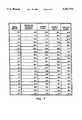
- FIG. 7is a chart of test results for a heated ice cube tray of the present invention.
- FIG. 8is a graph of resistance versus temperature for the test results shown in FIG. 7.
- FIG. 1shows a top view of a flexible heated tray 10 of the present invention.
- Tray 10includes a plurality of bays or compartments 12 designed to receive a predetermined quantity of liquid, such as water, to be frozen.
- Tray 10has a plurality of liquid distribution channels 14 formed therein that allow the liquid to flow between compartments 12 to facilitate the even filling thereof.
- Tray 10may be mounted within an ice maker (not shown) via connectors 16 which are fixably secured thereto. Connectors 16 allow tray 10 to be rotated about an axis generally indicated by line 17 in the direction generally indicated by arrow 18.
- a motor 20, indicated in schematic by a circle and M,is used to provide such rotation.
- a stop mechanism 22 of the ice makerfacilitates the removal of the frozen liquid from compartments 12.
- Tray 10includes a tab 24 formed thereon for cooperating with stop mechanism 22 in a manner discussed below.
- Stop mechanism 22includes a tongue 26 that engages tab 24 during rotation of tray 10 in the direction generally indicated by arrow 18 via motor 20. The engagement of tab 24 and tongue 26 allows tray 10 to flex so as to break the interface between the frozen liquid and compartments 12. Once the interface is broken, the frozen liquid ejects from compartments 12 via the influence of gravity.
- Electrodes 28 and 30are generally illustrated in FIG. 1 in two of the plurality of compartments 12 of tray 10. Electrodes 28 and 30 are electrically connected to wires 32 and arranged so that electrode 28 lies above electrode 30. Wires 32 supply current to electrodes 28 and 30 which are in heat conducting relation with compartments 12 of tray 10 so as to aid in the removal of frozen liquid therefrom as discussed more fully below. Although only a single electrode 28 and electrode 30 are shown in FIG. 1, it is to be understood that each of compartments 12 includes a electrode 28 and a electrode 30. That is, grids of electrodes 28 and 30 are disposed in cavities adjacent compartments 12 of tray 10 as discussed more fully below. These grids are electrically connected together as will be discussed below in connection with FIGS. 3 and 4.
- tray 10 in FIG. 1is shown as being adapted so as to be installed in an ice maker, it is to be understood that flexible tray 10 may also be used without an ice maker such that frozen liquid in compartments 12 could be dislodged by manual flexing. If tray 10 is not used in an ice maker, components thereof such as connectors 16 and engagement tab 24 are unnecessary.
- FIG. 2shows a cross-sectional view through a compartment 12 of tray 10 taken along line 2--2 of FIG. 1.
- Tray 10includes a body portion 34 that encases a conductive polymer 36 as well as top and bottom electrodes 28 and 30.
- conductive polymer 36is disposed in cavity 38 of body portion 34 such that it generally conforms to the shape and dimensions thereof.
- body 34is formed from a first portion 40 and a second portion 42 that are connected together at a joint 44. Portions 40 and 42 can be connected together via such methods as heat staking or ultrasonic welding.
- tray 10can be formed via a progressive insert molding process.
- Body portion 34 of tray 10is formed from an electrically insulative material and conductive polymer 36 is formed from an electrically conductive material.
- Possible materials for body 34include a variety of polymers such as polycarbonate, polyphenylene sulfide, or polyethylene sulfide.
- Conductive polymer 36may be formed from a polymer having a positive temperature coefficient or, alternatively, a thermoplastic.
- the conductive polymermay be composed of a high-density polyethylene based polymer to which carbon black is added in an amount equal to about 50% of the weight of the high-density polyethylene based polymer.
- electrodes 28 and 30carry current to and from conductive polymer 36. This causes conductive polymer 36 to reach a predetermined temperature so that an interface portion 45 of compartment 12 melts an adjacent portion of the frozen liquid therein. This makes removal of frozen liquid from compartment 12 easier.
- tray 10can be flexed such that the shape thereof is distorted to further facilitate removal of the frozen liquid from compartments 12.
- conductive polymer 36has several advantages over conventional heating via thermostatically controlled coils or wires.
- a polymer having a positive temperature coefficientis used, the resistance of conductive polymer 36 rises with temperature such that the heat generated by the material does not substantially increase beyond a maximum predetermined temperature once conductive polymer 36 reaches a high resistive state. This makes the temperature of conductive polymer 36 easier to control than conventional coils or wires because a thermostat is generally unnecessary. Rather, only a predetermined quantity of current is necessary in order to generate a desired heat energy output. Elimination of a thermostat has the advantage of reducing the number of components necessary to construct a heated ice cube tray.
- conductive polymer 36has the additional advantage of direct, immediate, and uniform heating of all surfaces in which it comes into contact unlike conventional coils or wires.
- a further advantage of the use of a conductive polymer 36is that it is more energy efficient than heating via conventional coils or wires. Experiments have shown that a heated ice cube tray with a polymer having a positive temperature coefficient consumes only 50 watts of power whereas a conventional heated ice cube tray utilizing coils or wires consumes 190 watts or almost four times as much power. This makes the heated ice cube tray of the present invention less expensive to operate.
- compartment 12has a generally cubic shape.
- Compartments 12 of the heated tray 10 of the present inventioncan be formed so as to provide a wide variety of additional aesthetically pleasing and functionally improved geometric shapes other than conventional crescent or semi-circular cross-sectional shapes used in automatic ice machines.
- crescent or semi-circular cross-sectional shape associated with frozen liquid formed from conventional ice makersresults from the necessity for the use of one or more ejector blades to mechanically remove the frozen liquid from the tray compartments. Ejector blades require a ramped surface formed in compartments of the tray in order to facilitate removal of frozen liquid therefrom.
- liquid distribution channels 14are generally U-shaped in cross-section. As discussed above in connection with FIG. 1, liquid distribution channels 14 facilitate the uniform and even filling of compartments 12 with a liquid to be frozen. Electrodes 28 and 30 are shown as being disposed on opposite sides of conductive polymer 36. Electrodes 28 and 30 and conductive polymer 36 form an electrically continuous circuit with conductive polymer 36 which acts as a resistor disposed between these electrodes. As current flows through electrodes 28 and 30, conductive polymer 36 is heated, as discussed above, to a predetermined temperature. Electrodes 28 and 30 can be configured and positioned to facilitate a generally uniform current flow density through conductive polymer 36. A generally uniform current flow density through conductive polymer 36 helps ensure a generally uniform heating thereof. In addition, when a polymer having a positive temperature coefficient is used for conductive polymer 36, its resistance increases at points of any "hot spots.” This increased resistance causes current to flow to cooler points of conductive polymer 36 to further provide a generally uniform heating.
- Electrodes 28 and 30are disposed within cavity 38 so that respective fingers 46 and spokes 48 extend along conductive polymer 36 disposed between sidewall portions 50 and 51 of compartment 12. Placement of conductive polymer 36 and electrodes 28 and 30 between sidewall portions 50 and 51 as well in bottom portion 52 of cavity 38 helps ensure that at least the majority of interface 45 between body 34 and the frozen liquid is melted.
- FIG. 3shows a top view of a pair of electrodes 28 of the present invention. Electrodes 28 may be formed from stamping, printing, wireform, or equivalent method. Electrodes 28 include generally rectangular portions 54 from which fingers 46 extend inward towards a center (not shown) of generally rectangular portion 54. Electrodes 28 are interconnected together via leads 58 such that each compartment 12 has an electrode 28 disposed therein.
- FIG. 4shows a top view of a pair of electrodes 30 of the present invention.
- electrodes 30may be formed from stamping, printing, wireform, or equivalent method.
- Electrodes 30include generally X-shaped portions 60 from which radiating spokes 48 extend. Electrodes 30 are interconnected together via leads 64 such that each compartment 12 of tray 10 has an electrode 30 disposed therein.
- electrodes 28 and 30help ensure a generally uniform current flow density through conductive polymer 36 of the present invention as discussed above.
- fingers 46 of generally rectangular portion 54 of electrode 28 and radiating spokes 48 of generally X-shaped portion 60 of electrode 30are respectively bent downwardly and upwardly along sidewall portions 50 and 51 of each of compartments 12. This configuration facilitates generally uniform current flow density through and resultant heating of conductive polymer 36 disposed in cavities 38 of tray 10. While particular shapes for electrodes 28 and 30 are shown in FIGS. 3 and 4, it is to be understood that other geometric configurations for electrodes 28 and 30 are within the scope and spirit of the present invention.
- FIG. 5shows an exploded perspective view of a rigid heated tray 66 of the present invention.
- Rigid heated tray 66includes a bottom or first tray portion 68 having a plurality of bays or compartments 70 therein.
- First tray portion 68is constructed from an electrically insulative material such as a variety of polymers including polycarbonate, polyphenylene sulfide, or polyethylene sulfide.
- compartments 70have a generally crescent or semi-circular cross-sectional shape 72.
- Notches 74are formed in first tray portion 68 for the provision of a liquid distribution channel similar to liquid distribution channels 14 formed in flexible heated tray 10 described above.
- Electrodes 76are disposed in compartments 70 of first tray portion 68 such that bottom (not shown) and sidewall portions 78 of first tray portion 68 are adjacent electrodes 76. Electrodes 76 terminate in generally hook-shaped ends 80 and have a generally crescent or semi-circular shape 82. A terminal portion 84 is formed on electrodes 76 for interconnection with a power supply (not shown).
- Second tray portion 86is shown as being formed such that its shape and dimensions generally conform to that of first tray portion 68.
- Second tray portion 86is formed from an electrically conductive polymer.
- Second tray portion 86may be made from a polymer having a positive temperature coefficient or, alternatively, from a thermoplastic.
- the conductive polymermay be composed of a high-density polyethylene based polymer to which carbon black is added in an amount equal to about 50% of the weight of the high-density polyethylene based polymer.
- Second tray portion 86includes a plurality of bays or compartments 88 that correspond in number to those of first tray portion 68. As can be seen from FIG. 5, compartments 88 have a generally crescent or semi-circular cross-sectional shape 90.
- Second tray portion 86includes a plurality of slots 92 formed in a bottom portion 94 thereof that receive wall portions 96 of first tray portion 68 when second tray portion 86 is coupled thereto. Second tray portion 86 includes a plurality of notches 98 formed therein for the provision of a liquid distribution channel as discussed above.
- Electrodes 100are shown as having a generally rectangular shape 110. As with electrodes 76, electrodes 100 are formed from an electrically conductive material. Electrodes 100 are disposed on top portions 112 of second tray portion 86. Electrodes 100 include bent portions 114 that are disposed in notches 98 of second tray portion 86. A terminal 116 is used to connect electrodes 100 with a power supply.
- a top or third tray portion 118is shown as being formed so as to generally conform to the shape and dimensions of first tray portion 68.
- Third tray portion 118includes a plurality of bays or compartments 120 corresponding in number to that of compartments 70 of first tray portion 68.
- compartments 120 of third tray portion 118have a generally crescent or semi-circular cross-sectional shape 122.
- the crescent or semi-circular cross-sectional shape of compartments 70, 88, and 120allows rigid heated tray 66 to be used in an ice maker having a plurality of rotating ejector blades. Compartments of trays used in automatic ice makers that have rotating ejector blades require at least one ramped surface in the direction of the rotation of the ejector blades.
- Third tray portion 118further includes a plurality of slots 124 formed in bottom 126 thereof in which wall portions 128 of second tray portion 86 are disposed. Third tray portion 118 includes a plurality of notches 130 that form a liquid distribution channel to facilitate the uniform and even filling of liquid in compartments 120. As with first tray portion 68, third tray portion 118 is constructed from an electrically insulative material such as a variety of polymers including polycarbonate, polyphenylene sulfide, or polyethylene sulfide.
- Respective first, second, and third tray portions 70, 86, and 118can be connected together by such methods as progressive insert or injection molding. Another possible method of formation of rigid heated tray 66 would be to injection mold second tray portion 86 from a conductive polymer material. First and third tray portions 70 and 118 could also be injection molded. Respective bottom and top electrodes 76 and 100 could then be respectively disposed in compartments 70 and on top portions 112. Tray portions 70, 86, and 118 could then be connected together via heat staking or ultrasonic welding.
- electrodes 76 and 100can be positioned adjacent the conductive polymer of second tray portion 86 so as to ensure a generally uniform current flow density and substantially uniform heating thereof.
- FIG. 6shows a cross-sectional view through line 6--6 of FIG. 5 for an assembled rigid heated tray 66 of the present invention.
- electrodes 76 and the generally hook-shaped portions 80 thereofextend well into sidewall portion 78 of compartments 70 of first tray portion 68. As discussed above, this is done in order to help provide a general uniform current flow density through the conductive polymer material from which a portion of rigid heated tray 66 is formed.
- FIG. 7is a chart of test results for a heated ice cube tray of the present invention.
- the ice cube traywas placed in still air at a temperature of -10° F. which was maintained throughout the test.
- a potential difference of 70 voltswas applied to the tray and current and tray temperature were recorded at 30 second intervals. Both dissipated power and the resistance of the conductive polymer were calculated from the known voltage and current.
- FIG. 8shows a graph of temperature versus time for the test results shown in FIG. 7.
- the temperature of the trayincreases with time. Initially, temperature change is larger for each incremental increase in time. However, the rate of incremental increase in temperature begins to decrease with time and eventually becomes substantially asymptotic.
- the conductive polymeris selected or chosen to have a maximum temperature of approximately 100 degrees Celsius.
Landscapes
- Engineering & Computer Science (AREA)
- Physics & Mathematics (AREA)
- Mechanical Engineering (AREA)
- Thermal Sciences (AREA)
- General Engineering & Computer Science (AREA)
- Compositions Of Macromolecular Compounds (AREA)
Abstract
Description
Claims (34)
Priority Applications (1)
| Application Number | Priority Date | Filing Date | Title |
|---|---|---|---|
| US08/374,895US5582754A (en) | 1993-12-08 | 1995-01-19 | Heated tray |
Applications Claiming Priority (2)
| Application Number | Priority Date | Filing Date | Title |
|---|---|---|---|
| US16392893A | 1993-12-08 | 1993-12-08 | |
| US08/374,895US5582754A (en) | 1993-12-08 | 1995-01-19 | Heated tray |
Related Parent Applications (1)
| Application Number | Title | Priority Date | Filing Date |
|---|---|---|---|
| US16392893AContinuation-In-Part | 1993-12-08 | 1993-12-08 |
Publications (1)
| Publication Number | Publication Date |
|---|---|
| US5582754Atrue US5582754A (en) | 1996-12-10 |
Family
ID=22592218
Family Applications (1)
| Application Number | Title | Priority Date | Filing Date |
|---|---|---|---|
| US08/374,895Expired - LifetimeUS5582754A (en) | 1993-12-08 | 1995-01-19 | Heated tray |
Country Status (1)
| Country | Link |
|---|---|
| US (1) | US5582754A (en) |
Cited By (58)
| Publication number | Priority date | Publication date | Assignee | Title |
|---|---|---|---|---|
| US5986239A (en)* | 1998-03-13 | 1999-11-16 | Sealed Air Corporation | Conductive warmer for foam packaging bags |
| US6093910A (en)* | 1998-10-30 | 2000-07-25 | Tachi-S Engineering, Usa Inc. | Electric seat heater |
| US6107607A (en)* | 1998-05-11 | 2000-08-22 | Imi Cornelius Inc. | Heated driptray |
| US6188051B1 (en) | 1999-06-01 | 2001-02-13 | Watlow Polymer Technologies | Method of manufacturing a sheathed electrical heater assembly |
| US6263158B1 (en) | 1999-05-11 | 2001-07-17 | Watlow Polymer Technologies | Fibrous supported polymer encapsulated electrical component |
| US6312886B1 (en) | 1996-12-06 | 2001-11-06 | The Secretary Of State For Defence In Her Brittanic Majesty's Government Of The United Kingdom Of Great Britain And Northern Ireland | Reaction vessels |
| US6369364B1 (en)* | 2000-04-13 | 2002-04-09 | Matsushita Electric Industrial Co., Ltd. | Electric thermo pot |
| US6392206B1 (en) | 2000-04-07 | 2002-05-21 | Waltow Polymer Technologies | Modular heat exchanger |
| US6392208B1 (en) | 1999-08-06 | 2002-05-21 | Watlow Polymer Technologies | Electrofusing of thermoplastic heating elements and elements made thereby |
| US6415501B1 (en) | 1999-10-13 | 2002-07-09 | John W. Schlesselman | Heating element containing sewn resistance material |
| US6432344B1 (en) | 1994-12-29 | 2002-08-13 | Watlow Polymer Technology | Method of making an improved polymeric immersion heating element with skeletal support and optional heat transfer fins |
| US6433317B1 (en) | 2000-04-07 | 2002-08-13 | Watlow Polymer Technologies | Molded assembly with heating element captured therein |
| US6436355B1 (en)* | 1996-12-06 | 2002-08-20 | Her Majesty The Queen In Right Of Canada, As Represented By The Secretary Of State For Defence | Electrically conducting polymer reaction vessels |
| US6516142B2 (en) | 2001-01-08 | 2003-02-04 | Watlow Polymer Technologies | Internal heating element for pipes and tubes |
| US6519835B1 (en) | 2000-08-18 | 2003-02-18 | Watlow Polymer Technologies | Method of formable thermoplastic laminate heated element assembly |
| US6588219B2 (en) | 2001-12-12 | 2003-07-08 | John Zevlakis | Commercial ice making apparatus and method |
| US20030148503A1 (en)* | 2000-03-08 | 2003-08-07 | Squirrell David James | Reaction system for thermal cycling |
| US6635471B1 (en)* | 1998-05-23 | 2003-10-21 | The Secretary Of State For Defence In Her Britannic Majesty's Government Of The United Kingdom Of Great Britain And Northern Ireland | Temperature control of incubation vessels using electrically conducting polymers |
| US20040237564A1 (en)* | 2001-12-12 | 2004-12-02 | John Zevlakis | Liquid milk freeze/thaw apparatus and method |
| US20050115266A1 (en)* | 2003-11-27 | 2005-06-02 | Lg Electronics Inc. | Icemaker for refrigerator |
| WO2006076981A1 (en)* | 2005-01-24 | 2006-07-27 | BSH Bosch und Siemens Hausgeräte GmbH | Ice-making machine |
| US20060272359A1 (en)* | 2005-06-01 | 2006-12-07 | Lg Electronics Inc. | Detergent dispensing apparatus of washing machine |
| US20060288726A1 (en)* | 2003-12-09 | 2006-12-28 | Kazuhiro Mori | Automatic ice maker |
| US20070045282A1 (en)* | 2002-02-11 | 2007-03-01 | The Trustees Of Dartmouth College | Systems and methods for modifying an ice-to-object interface |
| US20070079627A1 (en)* | 2005-10-06 | 2007-04-12 | Mile High Equipment Co. | Ice making method and machine with PETD harvest |
| US20070151282A1 (en)* | 2005-12-16 | 2007-07-05 | Lg Electronics Inc. | Icemaker and method for controlling the same |
| US20080131586A1 (en)* | 2005-02-01 | 2008-06-05 | Yuichiro Hama | Method for Manufacturing Fuel Cell and Apparatus for Manufacturing Fuel Cell |
| WO2008060696A3 (en)* | 2006-05-22 | 2008-09-12 | Dartmouth College | Pulse electrothermal deicing of complex shapes |
| US20090025401A1 (en)* | 2005-01-24 | 2009-01-29 | BSH Bosch und Siemens Hausgeräte GmbH | Ice Preparation Unit, Tray and Operational Method Therefor |
| US20090044559A1 (en)* | 2005-01-24 | 2009-02-19 | Bsh Bosch Und Siemens Hausgerate Gmbh | Ice Preparation Device |
| WO2009037125A1 (en)* | 2007-09-17 | 2009-03-26 | BSH Bosch und Siemens Hausgeräte GmbH | Ice cube preparer and method for operating the ice cube preparer |
| US20090113918A1 (en)* | 2005-01-24 | 2009-05-07 | Bsh Bosch Und Siemens Hausgeraete Gmbh | Ice-Making Machine |
| US20090126391A1 (en)* | 2005-01-24 | 2009-05-21 | Bsh Bosch Und Siemens Hausgeraete Gmbh, | Ice-Making Machine |
| US20090223230A1 (en)* | 2008-03-10 | 2009-09-10 | Young Jin Kim | Method of controlling ice making assembly for refrigerator |
| US20090272141A1 (en)* | 2005-01-24 | 2009-11-05 | Bsh Bosch Und Siemens Hausgerate Gmbh | Ice Preparation Device |
| US7638735B2 (en) | 2002-02-11 | 2009-12-29 | The Trustees Of Dartmouth College | Pulse electrothermal and heat-storage ice detachment apparatus and methods |
| US7703300B2 (en)* | 2004-06-22 | 2010-04-27 | The Trustees Of Dartmouth College | Pulse systems and methods for detaching ice |
| US20100205996A1 (en)* | 2009-02-19 | 2010-08-19 | Ducharme David R | Ice making device |
| US20120036872A1 (en)* | 2010-08-10 | 2012-02-16 | Brent Alden Junge | Method and apparatus for improving energy efficiency of an ice maker system |
| KR101188864B1 (en) | 2010-02-01 | 2012-10-08 | 김형열 | Ice tray and manufacturing method thereof |
| US8405002B2 (en) | 2002-02-11 | 2013-03-26 | The Trustees Of Dartmouth College | Pulse electrothermal mold release icemaker with safety baffles for refrigerator |
| US8424324B2 (en) | 2008-11-05 | 2013-04-23 | The Trustees Of Dartmouth College | Refrigerant evaporators with pulse-electrothermal defrosting |
| US20130239594A1 (en)* | 2012-03-16 | 2013-09-19 | Whirlpool Corporation | Ice maker with self-regulating ice mold & method of operating same |
| US8931296B2 (en) | 2009-11-23 | 2015-01-13 | John S. Chen | System and method for energy-saving inductive heating of evaporators and other heat-exchangers |
| US9016073B2 (en) | 2013-03-14 | 2015-04-28 | Whirlpool Corporation | Ice maker with heatless ice removal and method for heatless removal of ice |
| DE102014115849A1 (en) | 2014-10-30 | 2016-05-04 | Fraunhofer-Gesellschaft zur Förderung der angewandten Forschung e.V. | Method and arrangement for generating and thermally compressing oxygen |
| US20160341461A1 (en)* | 2015-05-22 | 2016-11-24 | Damar Williams | Ice cube tray device |
| US20170035245A1 (en)* | 2014-04-16 | 2017-02-09 | The Coleman Company, Inc. | Grill having multi-piece drip pan |
| US20170122639A1 (en)* | 2013-03-14 | 2017-05-04 | Whirlpool Corporation | Method to extend the life of a twist ice maker |
| US20180277872A1 (en)* | 2014-10-30 | 2018-09-27 | Hyundai Motor Company | Process for separating electrode for membrane-electrode assembly of fuel cell and apparatus therefor |
| US10267550B2 (en)* | 2014-07-23 | 2019-04-23 | Dae Chang Co., Ltd. | Tray for ice making machine, ice making machine comprising same, and refrigerator comprising ice making machine |
| US20190128584A1 (en)* | 2016-04-13 | 2019-05-02 | Whirlpool Corporation | Clear ice making appliance and method of same |
| US20210372682A1 (en)* | 2018-10-02 | 2021-12-02 | Lg Electronics Inc. | Refrigerator and controlling method therefor |
| US20220003479A1 (en)* | 2018-10-02 | 2022-01-06 | Lg Electronics Inc. | Refrigerator |
| US11435126B2 (en)* | 2018-08-23 | 2022-09-06 | Illinois Tool Works Inc. | Icemaker with thermoformed ice tray providing heating and phase change sensing |
| US20230168018A1 (en)* | 2018-11-16 | 2023-06-01 | Lg Electronics Inc. | Ice maker and refrigerator |
| US11709008B2 (en) | 2020-09-30 | 2023-07-25 | Midea Group Co., Ltd. | Refrigerator with multi-zone ice maker |
| US20230324097A1 (en)* | 2022-04-11 | 2023-10-12 | Midea Group Co., Ltd. | Refrigerator with a thermally conductive component with heater for ice maker |
Citations (34)
| Publication number | Priority date | Publication date | Assignee | Title |
|---|---|---|---|---|
| US1852064A (en)* | 1929-12-11 | 1932-04-05 | Raphael Sampson | Ice cube remover |
| US1977608A (en)* | 1929-07-23 | 1934-10-23 | John G Blystone | Ice tray heater |
| US2069567A (en)* | 1931-02-16 | 1937-02-02 | Henry L White | Means for removing ice cubes from refrigerator trays |
| US2112263A (en)* | 1936-06-09 | 1938-03-29 | William A Bohannon | Ice tray rack |
| US2115944A (en)* | 1937-01-22 | 1938-05-03 | Witt William M De | Ice cube releasing means |
| US2941377A (en)* | 1956-02-06 | 1960-06-21 | Westinghouse Electric Corp | Ice maker |
| US2941378A (en)* | 1957-02-28 | 1960-06-21 | Westinghouse Electric Corp | Ice making apparatus |
| US3020730A (en)* | 1959-08-03 | 1962-02-13 | Water Process Corp | Ice making apparatus |
| US3283284A (en)* | 1961-01-20 | 1966-11-01 | Eisler Paul | Electrical heating film |
| US3318105A (en)* | 1965-09-30 | 1967-05-09 | Borg Warner | Method and apparatus for producing clear ice under quiescent conditions |
| US3544762A (en)* | 1961-01-20 | 1970-12-01 | Paul Eisler | Method of separating portions of a transported body by resistance heating |
| US3720807A (en)* | 1972-05-01 | 1973-03-13 | Texas Instruments Inc | Food warming apparatus |
| US3745290A (en)* | 1972-03-01 | 1973-07-10 | Gen Electric | Inductively heatable utensils or vessels for heating,serving and storing food |
| US3775992A (en)* | 1972-07-17 | 1973-12-04 | Gen Motors Corp | Method and apparatus for making clear ice |
| US3784787A (en)* | 1971-08-20 | 1974-01-08 | Minnesota Mining & Mfg | Device for storing and cooking food |
| US3869596A (en)* | 1973-09-28 | 1975-03-04 | Safeway Products Inc | Cookware heater |
| US3952539A (en)* | 1974-11-18 | 1976-04-27 | General Motors Corporation | Water tray for clear ice maker |
| US4063068A (en)* | 1976-08-12 | 1977-12-13 | Minnesota Mining And Manufacturing Company | Food heating and cooking receptacle |
| US4134004A (en)* | 1977-07-18 | 1979-01-09 | American Can Company | Electrically heated pizza package |
| US4388607A (en)* | 1976-12-16 | 1983-06-14 | Raychem Corporation | Conductive polymer compositions, and to devices comprising such compositions |
| US4400614A (en)* | 1980-05-19 | 1983-08-23 | Raychem Corporation | PTC Devices and their preparation |
| US4543474A (en)* | 1979-09-24 | 1985-09-24 | Raychem Corporation | Layered self-regulating heating article |
| US4668857A (en)* | 1985-08-16 | 1987-05-26 | Belton Corporation | Temperature self-regulating resistive heating element |
| US4701597A (en)* | 1986-08-11 | 1987-10-20 | Bausch & Lomb Incorporated | Portable contact lens disinfecting apparatus |
| US4710612A (en)* | 1986-10-15 | 1987-12-01 | Lin Jong Tsuen | Structure of electric heater |
| DE3635286A1 (en)* | 1986-10-16 | 1988-04-21 | Lentia Gmbh | Surface heating element and process for producing it |
| US4756165A (en)* | 1987-08-03 | 1988-07-12 | Whirlpool Corporation | Single revolution ice maker |
| US4921648A (en)* | 1983-04-02 | 1990-05-01 | Raychem Corporation | Method of joining an article comprising a conductive polymer composition to a polymeric substrate |
| US4933534A (en)* | 1988-11-23 | 1990-06-12 | Cunningham Paul A | Electrical heater and plug |
| US4959528A (en)* | 1987-08-19 | 1990-09-25 | Malloy John R | Electrically heated vessel and base unit for use in a motor vehicle |
| US5111025A (en)* | 1990-02-09 | 1992-05-05 | Raychem Corporation | Seat heater |
| GB2252285A (en)* | 1991-01-29 | 1992-08-05 | British Aerospace | A method and apparatus for separating a frozen deposit from a substrate; Aircraft de-icing. |
| US5286952A (en)* | 1987-06-11 | 1994-02-15 | Raychem Corporation | Methods and devices which make use of conductive polymers to join articles |
| US5382384A (en)* | 1991-11-06 | 1995-01-17 | Raychem Corporation | Conductive polymer composition |
- 1995
- 1995-01-19USUS08/374,895patent/US5582754A/ennot_activeExpired - Lifetime
Patent Citations (34)
| Publication number | Priority date | Publication date | Assignee | Title |
|---|---|---|---|---|
| US1977608A (en)* | 1929-07-23 | 1934-10-23 | John G Blystone | Ice tray heater |
| US1852064A (en)* | 1929-12-11 | 1932-04-05 | Raphael Sampson | Ice cube remover |
| US2069567A (en)* | 1931-02-16 | 1937-02-02 | Henry L White | Means for removing ice cubes from refrigerator trays |
| US2112263A (en)* | 1936-06-09 | 1938-03-29 | William A Bohannon | Ice tray rack |
| US2115944A (en)* | 1937-01-22 | 1938-05-03 | Witt William M De | Ice cube releasing means |
| US2941377A (en)* | 1956-02-06 | 1960-06-21 | Westinghouse Electric Corp | Ice maker |
| US2941378A (en)* | 1957-02-28 | 1960-06-21 | Westinghouse Electric Corp | Ice making apparatus |
| US3020730A (en)* | 1959-08-03 | 1962-02-13 | Water Process Corp | Ice making apparatus |
| US3283284A (en)* | 1961-01-20 | 1966-11-01 | Eisler Paul | Electrical heating film |
| US3544762A (en)* | 1961-01-20 | 1970-12-01 | Paul Eisler | Method of separating portions of a transported body by resistance heating |
| US3318105A (en)* | 1965-09-30 | 1967-05-09 | Borg Warner | Method and apparatus for producing clear ice under quiescent conditions |
| US3784787A (en)* | 1971-08-20 | 1974-01-08 | Minnesota Mining & Mfg | Device for storing and cooking food |
| US3745290A (en)* | 1972-03-01 | 1973-07-10 | Gen Electric | Inductively heatable utensils or vessels for heating,serving and storing food |
| US3720807A (en)* | 1972-05-01 | 1973-03-13 | Texas Instruments Inc | Food warming apparatus |
| US3775992A (en)* | 1972-07-17 | 1973-12-04 | Gen Motors Corp | Method and apparatus for making clear ice |
| US3869596A (en)* | 1973-09-28 | 1975-03-04 | Safeway Products Inc | Cookware heater |
| US3952539A (en)* | 1974-11-18 | 1976-04-27 | General Motors Corporation | Water tray for clear ice maker |
| US4063068A (en)* | 1976-08-12 | 1977-12-13 | Minnesota Mining And Manufacturing Company | Food heating and cooking receptacle |
| US4388607A (en)* | 1976-12-16 | 1983-06-14 | Raychem Corporation | Conductive polymer compositions, and to devices comprising such compositions |
| US4134004A (en)* | 1977-07-18 | 1979-01-09 | American Can Company | Electrically heated pizza package |
| US4543474A (en)* | 1979-09-24 | 1985-09-24 | Raychem Corporation | Layered self-regulating heating article |
| US4400614A (en)* | 1980-05-19 | 1983-08-23 | Raychem Corporation | PTC Devices and their preparation |
| US4921648A (en)* | 1983-04-02 | 1990-05-01 | Raychem Corporation | Method of joining an article comprising a conductive polymer composition to a polymeric substrate |
| US4668857A (en)* | 1985-08-16 | 1987-05-26 | Belton Corporation | Temperature self-regulating resistive heating element |
| US4701597A (en)* | 1986-08-11 | 1987-10-20 | Bausch & Lomb Incorporated | Portable contact lens disinfecting apparatus |
| US4710612A (en)* | 1986-10-15 | 1987-12-01 | Lin Jong Tsuen | Structure of electric heater |
| DE3635286A1 (en)* | 1986-10-16 | 1988-04-21 | Lentia Gmbh | Surface heating element and process for producing it |
| US5286952A (en)* | 1987-06-11 | 1994-02-15 | Raychem Corporation | Methods and devices which make use of conductive polymers to join articles |
| US4756165A (en)* | 1987-08-03 | 1988-07-12 | Whirlpool Corporation | Single revolution ice maker |
| US4959528A (en)* | 1987-08-19 | 1990-09-25 | Malloy John R | Electrically heated vessel and base unit for use in a motor vehicle |
| US4933534A (en)* | 1988-11-23 | 1990-06-12 | Cunningham Paul A | Electrical heater and plug |
| US5111025A (en)* | 1990-02-09 | 1992-05-05 | Raychem Corporation | Seat heater |
| GB2252285A (en)* | 1991-01-29 | 1992-08-05 | British Aerospace | A method and apparatus for separating a frozen deposit from a substrate; Aircraft de-icing. |
| US5382384A (en)* | 1991-11-06 | 1995-01-17 | Raychem Corporation | Conductive polymer composition |
Cited By (99)
| Publication number | Priority date | Publication date | Assignee | Title |
|---|---|---|---|---|
| US6432344B1 (en) | 1994-12-29 | 2002-08-13 | Watlow Polymer Technology | Method of making an improved polymeric immersion heating element with skeletal support and optional heat transfer fins |
| US6312886B1 (en) | 1996-12-06 | 2001-11-06 | The Secretary Of State For Defence In Her Brittanic Majesty's Government Of The United Kingdom Of Great Britain And Northern Ireland | Reaction vessels |
| US6436355B1 (en)* | 1996-12-06 | 2002-08-20 | Her Majesty The Queen In Right Of Canada, As Represented By The Secretary Of State For Defence | Electrically conducting polymer reaction vessels |
| US5986239A (en)* | 1998-03-13 | 1999-11-16 | Sealed Air Corporation | Conductive warmer for foam packaging bags |
| US6107607A (en)* | 1998-05-11 | 2000-08-22 | Imi Cornelius Inc. | Heated driptray |
| US6635471B1 (en)* | 1998-05-23 | 2003-10-21 | The Secretary Of State For Defence In Her Britannic Majesty's Government Of The United Kingdom Of Great Britain And Northern Ireland | Temperature control of incubation vessels using electrically conducting polymers |
| US6093910A (en)* | 1998-10-30 | 2000-07-25 | Tachi-S Engineering, Usa Inc. | Electric seat heater |
| US6263158B1 (en) | 1999-05-11 | 2001-07-17 | Watlow Polymer Technologies | Fibrous supported polymer encapsulated electrical component |
| US6434328B2 (en) | 1999-05-11 | 2002-08-13 | Watlow Polymer Technology | Fibrous supported polymer encapsulated electrical component |
| US6188051B1 (en) | 1999-06-01 | 2001-02-13 | Watlow Polymer Technologies | Method of manufacturing a sheathed electrical heater assembly |
| US6392208B1 (en) | 1999-08-06 | 2002-05-21 | Watlow Polymer Technologies | Electrofusing of thermoplastic heating elements and elements made thereby |
| US6415501B1 (en) | 1999-10-13 | 2002-07-09 | John W. Schlesselman | Heating element containing sewn resistance material |
| US7537927B2 (en) | 2000-03-08 | 2009-05-26 | The Secretary Of State For Defence In Her Britannic Majesty's Government Of The United Kingdom Of Great Britain And Northern Ireland | Reaction system for thermal cycling |
| US20070262068A1 (en)* | 2000-03-08 | 2007-11-15 | The Secretary Of State For Defence | Reaction System for Thermal Cycling |
| US20030148503A1 (en)* | 2000-03-08 | 2003-08-07 | Squirrell David James | Reaction system for thermal cycling |
| US7264961B2 (en)* | 2000-03-08 | 2007-09-04 | The Secretary Of State For Defence In Her Britannic Majesty's Government Of The United Kingdom Of Great Britain And Northern Ireland | Reaction system for thermal cycling |
| US6433317B1 (en) | 2000-04-07 | 2002-08-13 | Watlow Polymer Technologies | Molded assembly with heating element captured therein |
| US6392206B1 (en) | 2000-04-07 | 2002-05-21 | Waltow Polymer Technologies | Modular heat exchanger |
| US6748646B2 (en)* | 2000-04-07 | 2004-06-15 | Watlow Polymer Technologies | Method of manufacturing a molded heating element assembly |
| US6369364B1 (en)* | 2000-04-13 | 2002-04-09 | Matsushita Electric Industrial Co., Ltd. | Electric thermo pot |
| US6519835B1 (en) | 2000-08-18 | 2003-02-18 | Watlow Polymer Technologies | Method of formable thermoplastic laminate heated element assembly |
| US6541744B2 (en) | 2000-08-18 | 2003-04-01 | Watlow Polymer Technologies | Packaging having self-contained heater |
| US6744978B2 (en) | 2001-01-08 | 2004-06-01 | Watlow Polymer Technologies | Small diameter low watt density immersion heating element |
| US6516142B2 (en) | 2001-01-08 | 2003-02-04 | Watlow Polymer Technologies | Internal heating element for pipes and tubes |
| US6539171B2 (en) | 2001-01-08 | 2003-03-25 | Watlow Polymer Technologies | Flexible spirally shaped heating element |
| US20040237564A1 (en)* | 2001-12-12 | 2004-12-02 | John Zevlakis | Liquid milk freeze/thaw apparatus and method |
| US6920764B2 (en) | 2001-12-12 | 2005-07-26 | John Zevlakis | Commercial ice making apparatus and method |
| US7059140B2 (en) | 2001-12-12 | 2006-06-13 | John Zevlakis | Liquid milk freeze/thaw apparatus and method |
| US6588219B2 (en) | 2001-12-12 | 2003-07-08 | John Zevlakis | Commercial ice making apparatus and method |
| US20040003621A1 (en)* | 2001-12-12 | 2004-01-08 | John Zevlakis | Commercial ice making apparatus and method |
| US7629558B2 (en) | 2002-02-11 | 2009-12-08 | The Trustees Of Dartmouth College | Systems and methods for modifying an ice-to-object interface |
| US8405002B2 (en) | 2002-02-11 | 2013-03-26 | The Trustees Of Dartmouth College | Pulse electrothermal mold release icemaker with safety baffles for refrigerator |
| US20070045282A1 (en)* | 2002-02-11 | 2007-03-01 | The Trustees Of Dartmouth College | Systems and methods for modifying an ice-to-object interface |
| US7638735B2 (en) | 2002-02-11 | 2009-12-29 | The Trustees Of Dartmouth College | Pulse electrothermal and heat-storage ice detachment apparatus and methods |
| US7493776B2 (en)* | 2003-11-27 | 2009-02-24 | Lg Electronics Inc. | Icemaker for refrigerator |
| EP1536195A3 (en)* | 2003-11-27 | 2006-10-25 | LG Electronics Inc. | Icemaker for refrigerator |
| US20050115266A1 (en)* | 2003-11-27 | 2005-06-02 | Lg Electronics Inc. | Icemaker for refrigerator |
| US20060288726A1 (en)* | 2003-12-09 | 2006-12-28 | Kazuhiro Mori | Automatic ice maker |
| US7444829B2 (en)* | 2003-12-19 | 2008-11-04 | Hoshizaki Denki Kabushiki Kaisha | Automatic ice making machine |
| US7703300B2 (en)* | 2004-06-22 | 2010-04-27 | The Trustees Of Dartmouth College | Pulse systems and methods for detaching ice |
| US20090272141A1 (en)* | 2005-01-24 | 2009-11-05 | Bsh Bosch Und Siemens Hausgerate Gmbh | Ice Preparation Device |
| DE102005003243B4 (en)* | 2005-01-24 | 2016-02-25 | BSH Hausgeräte GmbH | Ice makers |
| US20090025401A1 (en)* | 2005-01-24 | 2009-01-29 | BSH Bosch und Siemens Hausgeräte GmbH | Ice Preparation Unit, Tray and Operational Method Therefor |
| US20090044559A1 (en)* | 2005-01-24 | 2009-02-19 | Bsh Bosch Und Siemens Hausgerate Gmbh | Ice Preparation Device |
| US20090100856A1 (en)* | 2005-01-24 | 2009-04-23 | Bsh Bosch Und Siemens Hausgerate Gmbh | Ice-Making Machine |
| US20090113918A1 (en)* | 2005-01-24 | 2009-05-07 | Bsh Bosch Und Siemens Hausgeraete Gmbh | Ice-Making Machine |
| US20090126391A1 (en)* | 2005-01-24 | 2009-05-21 | Bsh Bosch Und Siemens Hausgeraete Gmbh, | Ice-Making Machine |
| US8601829B2 (en) | 2005-01-24 | 2013-12-10 | Bsh Bosch Und Siemens Hausgeraete Gmbh | Ice-making machine |
| WO2006076981A1 (en)* | 2005-01-24 | 2006-07-27 | BSH Bosch und Siemens Hausgeräte GmbH | Ice-making machine |
| US8181471B2 (en) | 2005-01-24 | 2012-05-22 | Bsh Bosch Und Siemens Hausgeraete Gmbh | Ice-making machine |
| US8104297B2 (en) | 2005-01-24 | 2012-01-31 | Bsh Bosch Und Siemens Hausgeraete Gmbh | Ice preparation unit, tray and operational method therefor |
| US20080131586A1 (en)* | 2005-02-01 | 2008-06-05 | Yuichiro Hama | Method for Manufacturing Fuel Cell and Apparatus for Manufacturing Fuel Cell |
| US20060272359A1 (en)* | 2005-06-01 | 2006-12-07 | Lg Electronics Inc. | Detergent dispensing apparatus of washing machine |
| US7661275B2 (en)* | 2005-10-06 | 2010-02-16 | Mile High Equipment L.L.C. | Ice making method and machine with PETD harvest |
| US20070079627A1 (en)* | 2005-10-06 | 2007-04-12 | Mile High Equipment Co. | Ice making method and machine with PETD harvest |
| US7810346B2 (en)* | 2005-12-16 | 2010-10-12 | Lg Electronics Inc. | Icemaker and method for controlling the same |
| US20070151282A1 (en)* | 2005-12-16 | 2007-07-05 | Lg Electronics Inc. | Icemaker and method for controlling the same |
| WO2008060696A3 (en)* | 2006-05-22 | 2008-09-12 | Dartmouth College | Pulse electrothermal deicing of complex shapes |
| WO2009037125A1 (en)* | 2007-09-17 | 2009-03-26 | BSH Bosch und Siemens Hausgeräte GmbH | Ice cube preparer and method for operating the ice cube preparer |
| US20100186421A1 (en)* | 2007-09-17 | 2010-07-29 | BSH Bosch und Siemens Hausgeräte GmbH | Ice cube preparer and method for operating the ice cube preparer |
| US20090223230A1 (en)* | 2008-03-10 | 2009-09-10 | Young Jin Kim | Method of controlling ice making assembly for refrigerator |
| US8424324B2 (en) | 2008-11-05 | 2013-04-23 | The Trustees Of Dartmouth College | Refrigerant evaporators with pulse-electrothermal defrosting |
| US8245527B2 (en)* | 2009-02-19 | 2012-08-21 | Ducharme David R | Ice making device |
| US20100205996A1 (en)* | 2009-02-19 | 2010-08-19 | Ducharme David R | Ice making device |
| US11585588B2 (en) | 2009-11-23 | 2023-02-21 | John S. Chen | System and method for energy-saving inductive heating of evaporators and other heat-exchangers |
| US8931296B2 (en) | 2009-11-23 | 2015-01-13 | John S. Chen | System and method for energy-saving inductive heating of evaporators and other heat-exchangers |
| KR101188864B1 (en) | 2010-02-01 | 2012-10-08 | 김형열 | Ice tray and manufacturing method thereof |
| US20120036872A1 (en)* | 2010-08-10 | 2012-02-16 | Brent Alden Junge | Method and apparatus for improving energy efficiency of an ice maker system |
| US20130239594A1 (en)* | 2012-03-16 | 2013-09-19 | Whirlpool Corporation | Ice maker with self-regulating ice mold & method of operating same |
| US9581373B2 (en)* | 2012-03-16 | 2017-02-28 | Whirlpool Corporation | Ice maker with self-regulating ice mold and method of operating same |
| US9016073B2 (en) | 2013-03-14 | 2015-04-28 | Whirlpool Corporation | Ice maker with heatless ice removal and method for heatless removal of ice |
| US10408519B2 (en)* | 2013-03-14 | 2019-09-10 | Whirlpool Corporation | Method to extend the life of a twist ice maker |
| US10126035B2 (en) | 2013-03-14 | 2018-11-13 | Whirlpool Corporation | Ice maker with heatless ice removal and method for heatless removal of ice |
| US9587870B2 (en) | 2013-03-14 | 2017-03-07 | Whirlpool Corporation | Ice maker with heatless ice removal and method for heatless removal of ice |
| US20170122639A1 (en)* | 2013-03-14 | 2017-05-04 | Whirlpool Corporation | Method to extend the life of a twist ice maker |
| US20170035245A1 (en)* | 2014-04-16 | 2017-02-09 | The Coleman Company, Inc. | Grill having multi-piece drip pan |
| US10267550B2 (en)* | 2014-07-23 | 2019-04-23 | Dae Chang Co., Ltd. | Tray for ice making machine, ice making machine comprising same, and refrigerator comprising ice making machine |
| DE102014115849A1 (en) | 2014-10-30 | 2016-05-04 | Fraunhofer-Gesellschaft zur Förderung der angewandten Forschung e.V. | Method and arrangement for generating and thermally compressing oxygen |
| US20180277872A1 (en)* | 2014-10-30 | 2018-09-27 | Hyundai Motor Company | Process for separating electrode for membrane-electrode assembly of fuel cell and apparatus therefor |
| US10549994B2 (en) | 2014-10-30 | 2020-02-04 | Fraunhofer-Gesellschaft Zur Foerderung Der Angewandten Forschung E. V. | Method and arrangement for the production and thermal compression of oxygen |
| US10749197B2 (en)* | 2014-10-30 | 2020-08-18 | Hyundai Motor Company | Process for separating electrode for membrane-electrode assembly of fuel cell and apparatus therefor |
| WO2016066160A1 (en) | 2014-10-30 | 2016-05-06 | Fraunhofer-Gesellschaft zur Förderung der angewandten Forschung e. V. | Method and arrangement for the production and thermal compression of oxygen |
| US20160341461A1 (en)* | 2015-05-22 | 2016-11-24 | Damar Williams | Ice cube tray device |
| US10174983B2 (en)* | 2015-05-22 | 2019-01-08 | Damar Williams | Ice cube tray device |
| US20190128584A1 (en)* | 2016-04-13 | 2019-05-02 | Whirlpool Corporation | Clear ice making appliance and method of same |
| US20190128583A1 (en)* | 2016-04-13 | 2019-05-02 | Whirlpool Corporation | Clear ice making appliance and method of same |
| US10921035B2 (en)* | 2016-04-13 | 2021-02-16 | Whirlpool Corporation | Clear ice making appliance and method of same |
| US11022359B2 (en)* | 2016-04-13 | 2021-06-01 | Whirlpool Corporation | Clear ice making appliance and method of same |
| US11073320B2 (en) | 2016-04-13 | 2021-07-27 | Whirlpool Corporation | Ice making assembly with twist ice tray and directional cooling |
| US11435126B2 (en)* | 2018-08-23 | 2022-09-06 | Illinois Tool Works Inc. | Icemaker with thermoformed ice tray providing heating and phase change sensing |
| US20210372682A1 (en)* | 2018-10-02 | 2021-12-02 | Lg Electronics Inc. | Refrigerator and controlling method therefor |
| US20220003479A1 (en)* | 2018-10-02 | 2022-01-06 | Lg Electronics Inc. | Refrigerator |
| US12209787B2 (en)* | 2018-10-02 | 2025-01-28 | Lg Electronics Inc. | Refrigerator |
| US12313321B2 (en)* | 2018-10-02 | 2025-05-27 | Lg Electronics Inc. | Refrigerator and controlling method therefor |
| US20230168018A1 (en)* | 2018-11-16 | 2023-06-01 | Lg Electronics Inc. | Ice maker and refrigerator |
| US12215909B2 (en)* | 2018-11-16 | 2025-02-04 | Lg Electronics Inc. | Ice maker and refrigerator |
| US11709008B2 (en) | 2020-09-30 | 2023-07-25 | Midea Group Co., Ltd. | Refrigerator with multi-zone ice maker |
| US20230324097A1 (en)* | 2022-04-11 | 2023-10-12 | Midea Group Co., Ltd. | Refrigerator with a thermally conductive component with heater for ice maker |
| US12339051B2 (en)* | 2022-04-11 | 2025-06-24 | Midea Group Co., Ltd. | Refrigerator with a thermally conductive component with heater for ice maker |
Similar Documents
| Publication | Publication Date | Title |
|---|---|---|
| US5582754A (en) | Heated tray | |
| US11435126B2 (en) | Icemaker with thermoformed ice tray providing heating and phase change sensing | |
| EP1653171B1 (en) | A method for making ice in a compact ice maker | |
| US7185508B2 (en) | Refrigerator with compact icemaker | |
| CA1314718C (en) | Ice maker with overtemperature protection | |
| US4756165A (en) | Single revolution ice maker | |
| US6216471B1 (en) | Method and apparatus for providing ice | |
| US20230349616A1 (en) | Hybrid ice maker | |
| EP3408598B1 (en) | Modular ice system | |
| US20230349617A1 (en) | Ice maker heater assemblies | |
| US20070079627A1 (en) | Ice making method and machine with PETD harvest | |
| KR20160004880A (en) | Ice maker and refrigerator with the same | |
| US20250216140A1 (en) | Ice maker and refrigerator | |
| US20180156515A1 (en) | Icemaker | |
| EP0657706A1 (en) | Control system for an electrically operated valve | |
| US3359747A (en) | Ice cube maker control | |
| JPS6241566A (en) | Water pan structure of automatic ice machine and conduction control system thereof | |
| KR20160127541A (en) | Ice maker | |
| KR20160109816A (en) | Ice maker including a direct connecting type high efficency ice moving heater | |
| KR20200144238A (en) | An ice tray, method for making the ice tray and an ice maker including the ice tray | |
| WO2007044222A2 (en) | Ice making method and machine with petd harvest | |
| KR20200048465A (en) | Ice maker and refrigerator incuding the same |
Legal Events
| Date | Code | Title | Description |
|---|---|---|---|
| AS | Assignment | Owner name:HEATERS ENGINEERING, INC., INDIANA Free format text:ASSIGNMENT OF ASSIGNORS INTEREST;ASSIGNORS:SMITH, KEVIN W.;HYGEMA, TERRY L.;REEL/FRAME:007364/0885 Effective date:19950116 | |
| STCF | Information on status: patent grant | Free format text:PATENTED CASE | |
| FEPP | Fee payment procedure | Free format text:PAYOR NUMBER ASSIGNED (ORIGINAL EVENT CODE: ASPN); ENTITY STATUS OF PATENT OWNER: LARGE ENTITY | |
| FPAY | Fee payment | Year of fee payment:4 | |
| FPAY | Fee payment | Year of fee payment:8 | |
| AS | Assignment | Owner name:DEKKO TECHNOLOGIES, INC., INDIANA Free format text:MERGER;ASSIGNOR:HEATERS ENGINEERING, INC.;REEL/FRAME:015361/0128 Effective date:20031226 | |
| AS | Assignment | Owner name:DEKKO TECHNOLOGIES, LLC,CALIFORNIA Free format text:ASSIGNMENT OF ASSIGNORS INTEREST;ASSIGNOR:DEKKO TECHNOLOGIES, INC.;REEL/FRAME:017957/0939 Effective date:20060720 Owner name:DEKKO TECHNOLOGIES, LLC, CALIFORNIA Free format text:ASSIGNMENT OF ASSIGNORS INTEREST;ASSIGNOR:DEKKO TECHNOLOGIES, INC.;REEL/FRAME:017957/0939 Effective date:20060720 | |
| AS | Assignment | Owner name:DYMAS FUNDING COMPANY, LLC, AS AGENT,ILLINOIS Free format text:SECURITY AGREEMENT;ASSIGNORS:PENT TECHNOLOGIES, INC.;DEKKO TECHNOLOGIES, LLC;REEL/FRAME:017971/0469 Effective date:20060720 Owner name:DYMAS FUNDING COMPANY, LLC, AS AGENT, ILLINOIS Free format text:SECURITY AGREEMENT;ASSIGNORS:PENT TECHNOLOGIES, INC.;DEKKO TECHNOLOGIES, LLC;REEL/FRAME:017971/0469 Effective date:20060720 | |
| AS | Assignment | Owner name:PENT TECHNOLOGIES, INC., INDIANA Free format text:ASSIGNMENT OF ASSIGNORS INTEREST;ASSIGNOR:DEKKO TECHNOLOGIES, LLC;REEL/FRAME:020325/0952 Effective date:20071227 Owner name:PENT TECHNOLOGIES, INC.,INDIANA Free format text:ASSIGNMENT OF ASSIGNORS INTEREST;ASSIGNOR:DEKKO TECHNOLOGIES, LLC;REEL/FRAME:020325/0952 Effective date:20071227 | |
| FPAY | Fee payment | Year of fee payment:12 | |
| AS | Assignment | Owner name:GROUP DEKKO, INC., INDIANA Free format text:MERGER;ASSIGNOR:PENT TECHNOLOGIES, INC.;REEL/FRAME:021936/0719 Effective date:20071227 Owner name:GROUP DEKKO, INC.,INDIANA Free format text:MERGER;ASSIGNOR:PENT TECHNOLOGIES, INC.;REEL/FRAME:021936/0719 Effective date:20071227 | |
| AS | Assignment | Owner name:WELLS FARGO CAPITAL FINANCE, LLC, AS AGENT, ILLINO Free format text:SECURITY AGREEMENT;ASSIGNOR:GROUP DEKKO, INC.;REEL/FRAME:026503/0966 Effective date:20110624 |