US5582728A - Pressure washer drum - Google Patents
Pressure washer drumDownload PDFInfo
- Publication number
- US5582728A US5582728AUS08/551,667US55166795AUS5582728AUS 5582728 AUS5582728 AUS 5582728AUS 55166795 AUS55166795 AUS 55166795AUS 5582728 AUS5582728 AUS 5582728A
- Authority
- US
- United States
- Prior art keywords
- drum
- hub
- deck
- secured
- plates
- Prior art date
- Legal status (The legal status is an assumption and is not a legal conclusion. Google has not performed a legal analysis and makes no representation as to the accuracy of the status listed.)
- Expired - Fee Related
Links
- 239000012530fluidSubstances0.000claimsdescription3
- 229920002678cellulosePolymers0.000claimsdescription2
- 239000001913celluloseSubstances0.000claimsdescription2
- 238000005406washingMethods0.000claimsdescription2
- 230000002028prematureEffects0.000abstractdescription3
- 238000003466weldingMethods0.000abstractdescription2
- 238000013461designMethods0.000description6
- 239000000706filtrateSubstances0.000description6
- 238000012545processingMethods0.000description4
- 239000013055pulp slurrySubstances0.000description3
- 239000002002slurrySubstances0.000description2
- 239000000126substanceSubstances0.000description2
- 230000007704transitionEffects0.000description2
- 229920003043Cellulose fiberPolymers0.000description1
- 229910000831SteelInorganic materials0.000description1
- 239000000654additiveSubstances0.000description1
- 230000004075alterationEffects0.000description1
- 238000009434installationMethods0.000description1
- 239000007788liquidSubstances0.000description1
- 238000012423maintenanceMethods0.000description1
- 238000004519manufacturing processMethods0.000description1
- 238000012986modificationMethods0.000description1
- 230000004048modificationEffects0.000description1
- 238000012856packingMethods0.000description1
- 239000000047productSubstances0.000description1
- 230000008439repair processEffects0.000description1
- 238000007789sealingMethods0.000description1
- 239000010959steelSubstances0.000description1
- XLYOFNOQVPJJNP-UHFFFAOYSA-NwaterSubstancesOXLYOFNOQVPJJNP-UHFFFAOYSA-N0.000description1
- 239000002023woodSubstances0.000description1
Images


Classifications
- D—TEXTILES; PAPER
- D21—PAPER-MAKING; PRODUCTION OF CELLULOSE
- D21F—PAPER-MAKING MACHINES; METHODS OF PRODUCING PAPER THEREON
- D21F1/00—Wet end of machines for making continuous webs of paper
- D21F1/60—Cylinder moulds
- B—PERFORMING OPERATIONS; TRANSPORTING
- B01—PHYSICAL OR CHEMICAL PROCESSES OR APPARATUS IN GENERAL
- B01D—SEPARATION
- B01D33/00—Filters with filtering elements which move during the filtering operation
- B01D33/06—Filters with filtering elements which move during the filtering operation with rotary cylindrical filtering surfaces, e.g. hollow drums
- B01D33/067—Construction of the filtering drums, e.g. mounting or sealing arrangements
- B—PERFORMING OPERATIONS; TRANSPORTING
- B01—PHYSICAL OR CHEMICAL PROCESSES OR APPARATUS IN GENERAL
- B01D—SEPARATION
- B01D33/00—Filters with filtering elements which move during the filtering operation
- B01D33/06—Filters with filtering elements which move during the filtering operation with rotary cylindrical filtering surfaces, e.g. hollow drums
- B01D33/073—Filters with filtering elements which move during the filtering operation with rotary cylindrical filtering surfaces, e.g. hollow drums arranged for inward flow filtration
- D—TEXTILES; PAPER
- D21—PAPER-MAKING; PRODUCTION OF CELLULOSE
- D21D—TREATMENT OF THE MATERIALS BEFORE PASSING TO THE PAPER-MAKING MACHINE
- D21D5/00—Purification of the pulp suspension by mechanical means; Apparatus therefor
- D21D5/02—Straining or screening the pulp
- D21D5/16—Cylinders and plates for screens
Definitions
- the inventionrelates to the field of pressure washers used in the processing of cellulose fibre pulp, and more particularly to an improved drum design for pressure washers.
- Rotary drum washers or filtersare used in the manufacture of paper products from pulp.
- a slurry of pulp fibres suspended in water and various chemical additivesis formed from wood chips.
- a sheet of pulpis formed from the slurry on the surface of a large drum by rotating the drum through the pulp slurry. The pulp sheet is then washed and de-watered on the outer surface of the drum, which has a perforated deck. The pulp sheet is then separated from the drum for further processing.
- Two general types of rotary drum washersare in common use--vacuum washer drums and pressure washer drums. In the vacuum washer drum, low pressure is maintained between an inner and an outer deck to draw the filtrate from the pulp sheet towards the centre of the drum.
- the drumIn the pressure washer drum, the drum is housed in a pressure chamber so that the exterior of the drum is maintained at a higher pressure than the interior, to force the filtrate through the filter deck of the drum.
- a prior art pressure washeris disclosed in U.S. Pat. No. 3,487,941 issued Jan. 6, 1970 to Griffina-Repola Oy.
- the cylindrical filter deckhas typically been supported on the axis of rotation by a number of annular spokes at either end of the drum.
- spokesare subjected to considerable forces, due to the combined weight of the drum and the external pressure on the surface of the drum, as well as rotational forces. For this reason the spokes are subject to premature failure, which results in a costly shutdown of the pulp processing facility in order to replace the drum, and expensive repairs. There is therefore a need for an improved design for the pressure washer drum which avoids such premature failure.
- the inventionprovides a rotatable filter drum, for use in washing cellulose pulp under pressure comprising:
- a cylindrical, perforated deckfor supporting a layer of pulp, supported on a plurality of annular rings coaxial to the shaft and longitudinal bars parallel to the shaft;
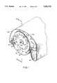
- FIG. 1is a perspective view of the pressure washer drum of the invention shown mounted for rotation in a pressure washer, with the end seal plate removed;
- FIG. 1Ais a cross-section along lines A--A of FIG. 1, with the end seal plate in place;
- FIG. 2is an end view of the pressure washer drum according to the invention, with the shroud removed and the interior structure shown in phantom outline;
- FIG. 3is a cross-section taken along lines 3--3 of FIG. 1, with the central section omitted along broken lines;
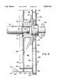
- FIG. 3Ais a detail view in cross-section taken at line C of FIG. 3;
- FIG. 4is a detail view of the hub of the invention.
- the pressure washer drum of the inventionis designated by reference numeral 10. It is suspended in the usual way on journals 74, 75 for rotation within a pressurized chamber 14, so that the interior of the drum 10 is at a lower pressure than the exterior.
- the pulp slurryis pumped into the inlet headbox 15 at a consistency of 2-4% BD.
- the pulp slurryforms a mat by dewatering as it travels with the drum through the forming zone 17.
- the pulp matis able to dewater in a relatively short time period compared to a vacuum washer due to the high pressure differential between the forming zone and the inside of the drum. Pressure ranges from 1.0 to 5.0 psig.
- a lip seal or bottom seal 19 placed across the full width of the drumprevents flow of pulp into the bottom of the vat and forces all of the pulp flow to rotate clockwise around the drum upon leaving the inlet headbox. Upon rotation of the drum 10 therefore a sheet 18 of pulp fibres adheres to the surface 20 of the drum.
- Surface 20 of the drumis perforated to permit filtrate to pass through the surface of the drum, to fall into the interior of the drum where it collects with the liquor in the tank 16.
- surface 20 of drum 10picks up the sheet 18 of pulp fibres which, after being drained of the filtrate, is separated from the surface 20 of drum 10 by knife edge 22 and falls into trough 24 for further processing.
- the outer surface 20 of the drumconsists of a perforated screen 26 which is supported on parallel circular ribs, referred to as flyrings 28 and longitudinal bars 30.
- the drum deckis supported by the end plates 32, 34.
- End plates 32, 34are each formed of two parallel circular plates of 3/4-inch steel, exterior end plates 40 and 44 and interior end plates 42 and 46.
- Radial ribs 48extend between the exterior and interior end plates.
- Circular rings 50, 52join the ends of each pair of end plates.
- the inner edge 51, 53 of rings 50, 52is extended and machined to a taper to provide a smooth transition of forces to the longitudinal bars 30.
- additional longitudinal bars 31 between longitudinal bars 30extending between exterior end plates 40, 44 and the second sets 29 of flyrings 28 to aid in the smooth transition from the end component sub-assembly 23 to the central cage subassembly of the drum.
- a two-by-two array of four holes 55is provided in circular rings 50, 52 in each compartment 54 formed by deck 20, ring 50 or 52 and adjacent longitudinal bars 30 and flyrings 28.
- the filtrateis permitted to flow from the compartments 54 into the space 56 between the interior and exterior plates 40, 44 and 42, 46.
- Both interior and exterior platesare provided with an array of openings 60 to permit the flow of filtrate between the interior of the drum and tank 13.
- Tank 13is separated from region 16 by the end seal subassembly 21.
- Openings 62are larger to permit workman access.
- the size and location of openings 60, 62is selected to provide the maximum strength of the end plates at the points of highest stress while permitting the necessary flow of liquid.
- the entire end subassembly component 23consisting of ribs 56 and end plates is thermally stress relieved.
- FIG. 4shows the hub design in greater detail.
- Pipe 12has stub shafts 64 of reduced diameter. End plates 40, 42, 44, 46 are welded to hub 66 at locations 68.
- Hub 66has a hollow central channel 67.
- a ring 70is bolted to the end of hub 66 and retains ring seal 72 to seal the hub against stub shaft 64.
- Stub shaft 64is inserted as shown in centre 67 of hub 66 and one RINGFEDERTM locking device 69 is inserted between the wall of channel 67 and the surface of end 64 and is tightened to secure hub 66 to end 64.
- Journal 74 at flange location 76is bolted to hub 66 by bolts 78.
- a shroud 80is welded to packing sleeve 83 to cover bolts 78.
- Journal 74is mounted in bearing assembly 85 in stuffing box 84 secured to wall 86 of pressure chamber 14.
- Ring 88 at the outer end of wall 86supports an annular end seal 90 of TEFLONTM or the like which has sealing and sliding contact with the outer edge 92 of end plates 40, 44.
- pipe 12is secured to hub 66 without welding and the welds joining the hub to the end plates are remote from the axis at a region of lower stresses.
- the welds between the spokes and the hubwere close to the axis and failure was typically at that point.
- the use of plates rather than spokesalso serves to spread the stresses over the area of the plates.
- the dissipation of stresses to the longitudinal barsis further improved by the tapering of extended edges 51 of rings 50, 52 and the installation of additional longitudinal bars 31 in the area adjacent to rings 50, 52.
- the use of a bolt-on style journalallows the journal to be removed from the drum for maintenance, whereas in prior designs the entire drum had to be removed.
Landscapes
- Chemical & Material Sciences (AREA)
- Chemical Kinetics & Catalysis (AREA)
- Engineering & Computer Science (AREA)
- Mechanical Engineering (AREA)
- Paper (AREA)
Abstract
Description
Claims (4)
Priority Applications (1)
| Application Number | Priority Date | Filing Date | Title |
|---|---|---|---|
| US08/551,667US5582728A (en) | 1995-11-01 | 1995-11-01 | Pressure washer drum |
Applications Claiming Priority (1)
| Application Number | Priority Date | Filing Date | Title |
|---|---|---|---|
| US08/551,667US5582728A (en) | 1995-11-01 | 1995-11-01 | Pressure washer drum |
Publications (1)
| Publication Number | Publication Date |
|---|---|
| US5582728Atrue US5582728A (en) | 1996-12-10 |
Family
ID=24202202
Family Applications (1)
| Application Number | Title | Priority Date | Filing Date |
|---|---|---|---|
| US08/551,667Expired - Fee RelatedUS5582728A (en) | 1995-11-01 | 1995-11-01 | Pressure washer drum |
Country Status (1)
| Country | Link |
|---|---|
| US (1) | US5582728A (en) |
Cited By (4)
| Publication number | Priority date | Publication date | Assignee | Title |
|---|---|---|---|---|
| US20030023248A1 (en)* | 1998-03-13 | 2003-01-30 | Parodi Juan C. | Systems and methods for applying a suture within a blood vesel lumen |
| US8992983B2 (en) | 2010-08-30 | 2015-03-31 | Pulmatrix, Inc. | Respirably dry powder comprising calcium lactate, sodium chloride and leucine |
| EP2987906A1 (en)* | 2014-08-22 | 2016-02-24 | GL&V Luxembourg S.a.r.l. | Pinned fly ring for rotary drum washer and method of manufacture |
| FR3029426A1 (en)* | 2014-12-08 | 2016-06-10 | E Beaudrey Et Cie | FILTRATION SYSTEM PROVIDED WITH HIGH MOVING MOBILE SEALING FOR FILTER DRUM |
Citations (8)
| Publication number | Priority date | Publication date | Assignee | Title |
|---|---|---|---|---|
| US811660A (en)* | 1903-01-08 | 1906-02-06 | Improved Paper Machinery Company | Pulp-treating machine. |
| US1608698A (en)* | 1920-10-09 | 1926-11-30 | Edwin G Staude | Attachment for paper machines |
| US2581210A (en)* | 1948-04-29 | 1952-01-01 | Forming Machine Company Of Ame | Positive pressure machine for forming continuous strips of asbestoscement compositions and the like |
| US2663432A (en)* | 1949-05-23 | 1953-12-22 | Kamyr Ab | Inclined rotary vacuum filter |
| US2952317A (en)* | 1953-02-27 | 1960-09-13 | Paper Machinery Ltd | Suction moulds |
| US3487941A (en)* | 1967-05-10 | 1970-01-06 | Pertti Olavi Haapamaki | Pressure washer |
| US4515693A (en)* | 1981-08-20 | 1985-05-07 | Ingersoll-Rand Company | Fiberglass-reinforced solid plastic drum |
| US4906364A (en)* | 1988-12-29 | 1990-03-06 | Ingersoll-Rand Company | Filter deck assembly sliding seal |
- 1995
- 1995-11-01USUS08/551,667patent/US5582728A/ennot_activeExpired - Fee Related
Patent Citations (8)
| Publication number | Priority date | Publication date | Assignee | Title |
|---|---|---|---|---|
| US811660A (en)* | 1903-01-08 | 1906-02-06 | Improved Paper Machinery Company | Pulp-treating machine. |
| US1608698A (en)* | 1920-10-09 | 1926-11-30 | Edwin G Staude | Attachment for paper machines |
| US2581210A (en)* | 1948-04-29 | 1952-01-01 | Forming Machine Company Of Ame | Positive pressure machine for forming continuous strips of asbestoscement compositions and the like |
| US2663432A (en)* | 1949-05-23 | 1953-12-22 | Kamyr Ab | Inclined rotary vacuum filter |
| US2952317A (en)* | 1953-02-27 | 1960-09-13 | Paper Machinery Ltd | Suction moulds |
| US3487941A (en)* | 1967-05-10 | 1970-01-06 | Pertti Olavi Haapamaki | Pressure washer |
| US4515693A (en)* | 1981-08-20 | 1985-05-07 | Ingersoll-Rand Company | Fiberglass-reinforced solid plastic drum |
| US4906364A (en)* | 1988-12-29 | 1990-03-06 | Ingersoll-Rand Company | Filter deck assembly sliding seal |
Non-Patent Citations (4)
| Title |
|---|
| Beloit Rauma, PFW Pro Feed Pressure Washer; date unknown.* |
| Beloit Rauma, PFW Pro-Feed Pressure Washer; date unknown. |
| Beloit, Belpond Washer; published 30 Dec., 1992. pp. 1 23.* |
| Beloit, Belpond Washer; published 30 Dec., 1992. pp. 1-23. |
Cited By (4)
| Publication number | Priority date | Publication date | Assignee | Title |
|---|---|---|---|---|
| US20030023248A1 (en)* | 1998-03-13 | 2003-01-30 | Parodi Juan C. | Systems and methods for applying a suture within a blood vesel lumen |
| US8992983B2 (en) | 2010-08-30 | 2015-03-31 | Pulmatrix, Inc. | Respirably dry powder comprising calcium lactate, sodium chloride and leucine |
| EP2987906A1 (en)* | 2014-08-22 | 2016-02-24 | GL&V Luxembourg S.a.r.l. | Pinned fly ring for rotary drum washer and method of manufacture |
| FR3029426A1 (en)* | 2014-12-08 | 2016-06-10 | E Beaudrey Et Cie | FILTRATION SYSTEM PROVIDED WITH HIGH MOVING MOBILE SEALING FOR FILTER DRUM |
Similar Documents
| Publication | Publication Date | Title |
|---|---|---|
| US5647982A (en) | Vacuum filter element | |
| US4543181A (en) | Medium consistency flat disk pressure screen | |
| CA2003108A1 (en) | Filter separator for separating a composite fluid | |
| FI81143C (en) | SILANORDNING MED ANORDNING FOER REDUKTION AV REJEKT. | |
| US4565124A (en) | Screw presses | |
| US5575395A (en) | Method and apparatus for screening fibrous suspensions | |
| US5582728A (en) | Pressure washer drum | |
| US3387708A (en) | Paper machine screen | |
| US8281936B2 (en) | Vacuum washer drum having a center and end drains and method for draining | |
| US5221434A (en) | Method for treating fiber suspensions | |
| CA2161851C (en) | Pressure washer drum | |
| US4889625A (en) | Filter for concentrating suspensions | |
| US3504802A (en) | Rotary drum filter | |
| EP2504075B1 (en) | Arrangement for sealing a press | |
| US3456793A (en) | Dual pressure stock screen | |
| US7285180B2 (en) | Perforated deck made out of a plurality of segments | |
| CN101189389A (en) | Device for processing cellulose pulp in a pulp washer with a device for removing seals | |
| US4333836A (en) | Cellular drum filter for the dewatering of fiber suspensions | |
| US4961844A (en) | Apparatus for separating a suspension of fibrous cellulose pulp | |
| US5051167A (en) | Apparatus for screening a suspension of fibrous cellulose material | |
| US3754660A (en) | Apparatus for extracting fluid from pulp | |
| US5203968A (en) | Apparatus for treating fiber suspensions having rotatable liquid permeable treatment ducts | |
| US4106980A (en) | Thickener apparatus including a shaftless cylinder mold | |
| US3386584A (en) | Valveless drum filter | |
| US3399772A (en) | Duplex pulp screen |
Legal Events
| Date | Code | Title | Description |
|---|---|---|---|
| AS | Assignment | Owner name:TRISTAR INDUSTRIES LTD., CANADA Free format text:ASSIGNMENT OF ASSIGNORS INTEREST;ASSIGNOR:GADALA, MOHAMED S.;REEL/FRAME:008116/0468 Effective date:19960308 Owner name:TRISTAR INDUSTRIES, LTD., CANADA Free format text:ASSIGNMENT OF ASSIGNORS INTEREST;ASSIGNORS:TAYLER, MARK;HODGINS, GARY;REEL/FRAME:008116/0494;SIGNING DATES FROM 19960202 TO 19960312 | |
| FEPP | Fee payment procedure | Free format text:PAYOR NUMBER ASSIGNED (ORIGINAL EVENT CODE: ASPN); ENTITY STATUS OF PATENT OWNER: SMALL ENTITY | |
| FEPP | Fee payment procedure | Free format text:PAT HOLDER CLAIMS SMALL ENTITY STATUS - SMALL BUSINESS (ORIGINAL EVENT CODE: SM02); ENTITY STATUS OF PATENT OWNER: SMALL ENTITY | |
| FPAY | Fee payment | Year of fee payment:4 | |
| REMI | Maintenance fee reminder mailed | ||
| FPAY | Fee payment | Year of fee payment:8 | |
| SULP | Surcharge for late payment | Year of fee payment:7 | |
| REMI | Maintenance fee reminder mailed | ||
| LAPS | Lapse for failure to pay maintenance fees | ||
| STCH | Information on status: patent discontinuation | Free format text:PATENT EXPIRED DUE TO NONPAYMENT OF MAINTENANCE FEES UNDER 37 CFR 1.362 | |
| FP | Lapsed due to failure to pay maintenance fee | Effective date:20081210 |