US5582610A - Grooved slider electrode for a resectoscope - Google Patents
Grooved slider electrode for a resectoscopeDownload PDFInfo
- Publication number
- US5582610A US5582610AUS08/312,957US31295794AUS5582610AUS 5582610 AUS5582610 AUS 5582610AUS 31295794 AUS31295794 AUS 31295794AUS 5582610 AUS5582610 AUS 5582610A
- Authority
- US
- United States
- Prior art keywords
- electrode
- conductive core
- slider
- tissue
- grooved slider
- Prior art date
- Legal status (The legal status is an assumption and is not a legal conclusion. Google has not performed a legal analysis and makes no representation as to the accuracy of the status listed.)
- Expired - Lifetime
Links
- 210000001519tissueAnatomy0.000claimsabstractdescription80
- 238000000034methodMethods0.000claimsabstractdescription48
- 210000002307prostateAnatomy0.000claimsabstractdescription19
- 239000004020conductorSubstances0.000claimsabstractdescription14
- 238000005345coagulationMethods0.000claimsdescription13
- 230000015271coagulationEffects0.000claimsdescription13
- 239000003381stabilizerSubstances0.000claimsdescription9
- 239000012530fluidSubstances0.000claimsdescription5
- 230000002262irrigationEffects0.000claimsdescription3
- 238000003973irrigationMethods0.000claimsdescription3
- 239000003989dielectric materialSubstances0.000claimsdescription2
- 230000000087stabilizing effectEffects0.000claimsdescription2
- 230000008016vaporizationEffects0.000abstractdescription16
- 239000000463materialSubstances0.000abstract1
- 239000000835fiberSubstances0.000description13
- 238000009834vaporizationMethods0.000description11
- 238000002271resectionMethods0.000description9
- 208000032843HemorrhageDiseases0.000description8
- 230000001112coagulating effectEffects0.000description6
- 210000003708urethraAnatomy0.000description6
- 206010028980NeoplasmDiseases0.000description5
- 238000002679ablationMethods0.000description5
- 230000000740bleeding effectEffects0.000description5
- 230000000007visual effectEffects0.000description4
- 238000010586diagramMethods0.000description3
- 230000000694effectsEffects0.000description3
- 230000002357endometrial effectEffects0.000description3
- 239000007788liquidSubstances0.000description3
- 206010020880HypertrophyDiseases0.000description2
- 230000006378damageEffects0.000description2
- 238000002224dissectionMethods0.000description2
- 238000001704evaporationMethods0.000description2
- 230000008020evaporationEffects0.000description2
- 239000011810insulating materialSubstances0.000description2
- 239000000203mixtureSubstances0.000description2
- 239000013307optical fiberSubstances0.000description2
- 238000011471prostatectomyMethods0.000description2
- 206010004446Benign prostatic hyperplasiaDiseases0.000description1
- 206010014418Electrolyte imbalanceDiseases0.000description1
- 206010021639IncontinenceDiseases0.000description1
- 201000004458MyomaDiseases0.000description1
- 208000004403Prostatic HyperplasiaDiseases0.000description1
- 206010038967Retrograde ejaculationDiseases0.000description1
- VYPSYNLAJGMNEJ-UHFFFAOYSA-NSilicium dioxideChemical compoundO=[Si]=OVYPSYNLAJGMNEJ-UHFFFAOYSA-N0.000description1
- 230000003187abdominal effectEffects0.000description1
- 238000010521absorption reactionMethods0.000description1
- 235000014121butterNutrition0.000description1
- 201000011510cancerDiseases0.000description1
- 238000003763carbonizationMethods0.000description1
- 208000031513cystDiseases0.000description1
- 230000003111delayed effectEffects0.000description1
- 201000010099diseaseDiseases0.000description1
- 208000037265diseases, disorders, signs and symptomsDiseases0.000description1
- 210000004696endometriumAnatomy0.000description1
- 238000010304firingMethods0.000description1
- 230000023597hemostasisEffects0.000description1
- 238000002430laser surgeryMethods0.000description1
- 201000010260leiomyomaDiseases0.000description1
- 230000007774longtermEffects0.000description1
- 230000036210malignancyEffects0.000description1
- 230000010355oscillationEffects0.000description1
- 208000003154papillomaDiseases0.000description1
- 230000001575pathological effectEffects0.000description1
- 230000000149penetrating effectEffects0.000description1
- 210000004872soft tissueAnatomy0.000description1
- 241000894007speciesSpecies0.000description1
- 210000005070sphincterAnatomy0.000description1
- 238000001356surgical procedureMethods0.000description1
- 230000002459sustained effectEffects0.000description1
- 238000002560therapeutic procedureMethods0.000description1
- 230000000472traumatic effectEffects0.000description1
- 210000004291uterusAnatomy0.000description1
Images


Classifications
- A—HUMAN NECESSITIES
- A61—MEDICAL OR VETERINARY SCIENCE; HYGIENE
- A61B—DIAGNOSIS; SURGERY; IDENTIFICATION
- A61B18/00—Surgical instruments, devices or methods for transferring non-mechanical forms of energy to or from the body
- A61B18/04—Surgical instruments, devices or methods for transferring non-mechanical forms of energy to or from the body by heating
- A61B18/12—Surgical instruments, devices or methods for transferring non-mechanical forms of energy to or from the body by heating by passing a current through the tissue to be heated, e.g. high-frequency current
- A61B18/14—Probes or electrodes therefor
- A61B18/149—Probes or electrodes therefor bow shaped or with rotatable body at cantilever end, e.g. for resectoscopes, or coagulating rollers
- A—HUMAN NECESSITIES
- A61—MEDICAL OR VETERINARY SCIENCE; HYGIENE
- A61B—DIAGNOSIS; SURGERY; IDENTIFICATION
- A61B18/00—Surgical instruments, devices or methods for transferring non-mechanical forms of energy to or from the body
- A61B18/04—Surgical instruments, devices or methods for transferring non-mechanical forms of energy to or from the body by heating
- A61B18/12—Surgical instruments, devices or methods for transferring non-mechanical forms of energy to or from the body by heating by passing a current through the tissue to be heated, e.g. high-frequency current
- A61B18/14—Probes or electrodes therefor
- A61B18/1485—Probes or electrodes therefor having a short rigid shaft for accessing the inner body through natural openings
- A—HUMAN NECESSITIES
- A61—MEDICAL OR VETERINARY SCIENCE; HYGIENE
- A61B—DIAGNOSIS; SURGERY; IDENTIFICATION
- A61B18/00—Surgical instruments, devices or methods for transferring non-mechanical forms of energy to or from the body
- A61B2018/00315—Surgical instruments, devices or methods for transferring non-mechanical forms of energy to or from the body for treatment of particular body parts
- A61B2018/00505—Urinary tract
- A—HUMAN NECESSITIES
- A61—MEDICAL OR VETERINARY SCIENCE; HYGIENE
- A61B—DIAGNOSIS; SURGERY; IDENTIFICATION
- A61B18/00—Surgical instruments, devices or methods for transferring non-mechanical forms of energy to or from the body
- A61B2018/00315—Surgical instruments, devices or methods for transferring non-mechanical forms of energy to or from the body for treatment of particular body parts
- A61B2018/00547—Prostate
- A—HUMAN NECESSITIES
- A61—MEDICAL OR VETERINARY SCIENCE; HYGIENE
- A61B—DIAGNOSIS; SURGERY; IDENTIFICATION
- A61B18/00—Surgical instruments, devices or methods for transferring non-mechanical forms of energy to or from the body
- A61B2018/00315—Surgical instruments, devices or methods for transferring non-mechanical forms of energy to or from the body for treatment of particular body parts
- A61B2018/00559—Female reproductive organs
- A—HUMAN NECESSITIES
- A61—MEDICAL OR VETERINARY SCIENCE; HYGIENE
- A61B—DIAGNOSIS; SURGERY; IDENTIFICATION
- A61B18/00—Surgical instruments, devices or methods for transferring non-mechanical forms of energy to or from the body
- A61B2018/00571—Surgical instruments, devices or methods for transferring non-mechanical forms of energy to or from the body for achieving a particular surgical effect
- A61B2018/00577—Ablation
- A—HUMAN NECESSITIES
- A61—MEDICAL OR VETERINARY SCIENCE; HYGIENE
- A61B—DIAGNOSIS; SURGERY; IDENTIFICATION
- A61B18/00—Surgical instruments, devices or methods for transferring non-mechanical forms of energy to or from the body
- A61B2018/00571—Surgical instruments, devices or methods for transferring non-mechanical forms of energy to or from the body for achieving a particular surgical effect
- A61B2018/00625—Vaporization
- A—HUMAN NECESSITIES
- A61—MEDICAL OR VETERINARY SCIENCE; HYGIENE
- A61B—DIAGNOSIS; SURGERY; IDENTIFICATION
- A61B18/00—Surgical instruments, devices or methods for transferring non-mechanical forms of energy to or from the body
- A61B18/04—Surgical instruments, devices or methods for transferring non-mechanical forms of energy to or from the body by heating
- A61B18/12—Surgical instruments, devices or methods for transferring non-mechanical forms of energy to or from the body by heating by passing a current through the tissue to be heated, e.g. high-frequency current
- A61B18/14—Probes or electrodes therefor
- A61B2018/1405—Electrodes having a specific shape
- A61B2018/1425—Needle
- A61B2018/143—Needle multiple needles
Definitions
- the inventionrelates generally to an electrode having a slider element adapted for use with an endoscope for tissue ablation and more particularly relates to an electrode having a grooved slider for use in performing procedures, such as, for example, in the genitourinary tract on soft tissue, including bladder and prostrate, for hemostasis, incision, excision and ablation or in performing gynecological procedures such as endometrial ablation.
- Resectoscopes used for transurethral resection of the prostratehave four elements, a resectoscope sheath, sometimes referred to as a sheath or an outer sheath, a working element, an electrode and a telescope.
- the electrodesare operatively connected to a working element and a telescope is slideably inserted through the working element and into position along side of the electrode.
- Certain electrodesinclude an electrode stabilizer which is adapted to receive the telescope. The so assembled working element, telescope and electrode are removeably inserted into the sheath to perform a procedure.
- the outer sheathhaving an obturator and telescope inserted therein, is visually passed through the urethra to the vicinity of the prostrate and/or bladder neck.
- the electrodewhich is also known as a resectoscope electrode, is typically in the form of a cutting loop located at the distal end of an electrode lead member.
- An electrosurgical currentwhich may be either a coagulation current, a cutting current or some blend thereof is applied to the cutting loop.
- the energized cutting loopis moved across and cuts the tissue being treated.
- the cutting loopcan also be used to coagulate the wound.
- the peak voltage of the electrosurgical cutting currentsare typically in the range of 225 volts to about 250 volts at a power level of between about 120 watts to about 200 watts.
- a resectoscope electrode having a stabilized cutting loop for a resectoscopeis described in U.S. Pat. 4,917,082.
- the resectoscope electrode described in U.S. Pat. 4,917,082is adapted for use with a urological endoscope or resectoscope.
- the electrodecomprises an electrode lead, an electrode end and an electrode stabilizer.
- U.S. Pat. 4,917,082discloses that the electrode may take the form of a coagulating electrode, knife electrode, retrograde knife electrode, punctate electrode or roller electrode having a smooth exterior surface.
- the Auhll Referencediscussed three electrode structures, namely: (1) an electrosurgical cutting loop to treat fibroid tissues; (2) a roller ball having a-smooth exterior surface for endometrial ablation (which is cauterization of the endometrium); and (3) electrosurgical needle to cut through and destroy tissue producing intrauterine synechia.
- the voltage of the electrosurgical cutting currentsare typically in the range of 225 volts to about 250 volts at a power level of between 60 watts and 100 watts.
- Nd:YAG lasersfor the coagulation and vaporization of prostate tissue generally referred to as abdominal tissue.
- optical fibers capable of deflecting a Nd:YAG laser energy beam about 70° to about 90° to the axis of the optical fiber(generally known as side-firing fibers) have been developed.
- the Narayan et al. Referencediscusses the use of laser surgery for BPH as a promising alternative to traditional TURP.
- the Narayan et al Referencediscloses that in prostate surgery tissue evaporization referred to as Transurethral Evaporization of Prostate Tissue ("TUEP") was achieved by holding the laser fiber in contact with the area to be treated.
- the TUEPwas performed using an Ultraline Laser Fiber manufactured by Heraeus LaserSonics, Milpitas, Calif.
- the Ultraline Laser Fiberuses a 600 ⁇ m internal reflector fiber covered by a quartz glass cap that reflects the Nd:YAG beam at 80 degrees to the fiber axis.
- This fibertransmits a high-power density beam (spot size of 700 ⁇ m and divergence of 17 degrees, giving a power density at 60 watts to 80 watts of 15,600 to 21,231 W/cm 2 ) 1 mm from the fiber tip.
- a 23 French cystoscope(CIRCON ACMI, Stamford, Conn.) equipped with an 8 French laser bridge and a continuous flow system was used for the procedure.
- Tissue evaporationwas achieved by holding the laser fiber in contact with the area to be treated, and by dragging at a rate of 1 cm/20 seconds of laser energy delivery. At the beginning of each furrow dragging was commenced one bulling was seen indicating tissue evaporation. Dragging the fiber at a rate of 1 cm/20 seconds resulted in a furrow 5 to 7 mm deep with a 3 to 4 mm rim of coagulated tissue immediately next to it.”
- T.U.Dtransurethral desiccation of the prostate
- T.V.P.transurethral vaporization of the prostate
- T.V.P.has the advantage that it causes little or not bleeding, fluid absorption or electrolyte imbalance. Since the residual desiccated tissue (adequate for pathologic review) is removed at the end of the procedure, there is no slough or delayed bleeding (open vessels are closed without retraction). The patient can leave the hospital, voiding (76%) within the 23 hour observation time in most instances.
- a new improved scored ball loop (A.C.M.I.) to be used with a continuous flow resectoscopehas become available.
- T.V.P.is a short procedure without sphincter damage which preserves antegrade ejaculation and has a low (2-3%) subsequent procedure rate. Our experience with the last 100 consecutive patients will be detailed.”
- the first use of electrosurgical generator for prostatic resection using only an R.F. cutting currentwas in 1931, and the electrosurgical generator was a McCarthy Surgical Unit Type 504A sold by the Complex Oscillator Corporation (the "McCarthy Surgical Unit”).
- the McCarthy Surgical Unitwas a highly efficient vacuum tube generator producing sustained oscillation of high frequency.
- the McCarthy Surgical Unitwas capable of being used for numerous procedures including prostatic resection.
- the McCarthy Surgical Unit manualstates the following with respect to prostatic resection:
- the McCarthy Unitprovides every modality. Every purpose which requires the use of high frequency current is served; fulguration of cysts, papillomata, tumors, etc., coagulation control of bleeding, resection and treatment.
- the current supplied by the type 504-A unitalthough very efficacious in resection, shows no effect on delicate insulating materials, greatly prolonging the useful life of urological instruments and electrodes.
- the selective foot switchpermits hemorrhage control with the same electrode used for resection, without the necessity of changing the controls on the apparatus.”
- the McCarthy Surgical Unit manualstates that the McCarthy Surgical Unit can be used for coagulation as follows:
- the unitgenerates by one type of current, and the controls merely provide the means for adjusting its intensity. It has been established that the same current that shows such admirable cutting characteristics is also the most effective for coagulation. By virtue of its penetrating quality the time necessary for coagulating tumor masses or malignancies has been greatly reduced. Sections of coagulated areas show a tapering off into unaffected tissue that practically eliminates the possibility of secondary hemorrhage. Tumor masses show a remarkable shrinkage during application, proportional to their fluid content.
- the technique used in coagulation with this type of currentis the same as used for tissue destruction and for hemorrhage control.
- the electrodemust be placed in contact with the area to be treated before the current is turned on. After treatment the current must be off before the electrode is removed. No attempt should be made to ply the area with sparks. In following this technique there is no possibility of carbonization, and no tissue can adhere to the electrode.”
- the McCarthy Surgical Unitutilized for coagulation and dissection a smooth ball shaped electrode having a 3/16 inch (4 mm) diameter.
- the McCarthy Surgical Unitutilized a control panel having two dials.
- the first dialwas referred to as the Range Selector (R.S.) having three ranges, a low, medium and high, each representing one third of the current output.
- the second dialwas referred as the Current Intensity Control (C.I.C.) and provided smooth linear adjustment over each range.
- the Range Selectorwas a course adjustment and the Current Intensity Control was a fine adjustment.
- the only current produced by the McCarthy Surgical Unitwas a cutting current.
- the maximum currentwas in the order of 2,600 milliamperes.
- a plate electrodewas placed under the patient and connected to an indifferent, terminal which is usually a ground terminal, to ground the patient.
- the resulting coagulation layer of the heated tissuehad a thickness in the order of 0.5 mm to about 1 mm which appeared sufficient to stop bleeding.
- the electrodecomprises an electrode lead member having an elongated conductor member having a first end and a second end with an insulative cover extended therebetween.
- the first end of the electrode memberhas a protruding electrode which is adapted to be electrically connected to an electrosurgical generator.
- the second end of the electrode memberterminates in an active member.
- the electrodeincludes an electrode support member operatively connected to the loading member and includes an elongated semi-rigid bifurcated arm terminating in a conductive core spaced a predetermined distance from the active member.
- the electrode support memberhas a grooved slider having a central opening extending therethrough for fixedly mounting the grooved slider on the conductive core.
- a method for treating tissuecomprises the steps of: (i) inserting a sheath having a visual obturator into a urethra; (ii) removing the visual obturator leaving the outer sheath in the urethra; (iii) inserting into a resectoscope working element a telescope and an electrode wherein the electrode has an electrode lead member which includes an elongated conductor member having a first end and a second end with an insulative cover extended therebetween wherein said first end has a protruding electrode adapted to be electrically connected to an electrosurgical generator and wherein said second end terminates in an active member and having an electrode support having an elongated semi-rigid bifurcated arm terminating in a conductive core spaced a predetermined distance from the active member and wherein the electrode support member has a grooved slider having a central opening extending therethrough for fixedly mounting the grooved slider on the hub; (iv) passing the resecto
- scored roller electrode in a resectoscope for treatment of prostatic tissue using cutting current R.F. signalsappeared to show that a scored roller ball electrode would successfully vaporize prostatic tissue.
- the removal rate of tissue, the time required for completion of a procedure and the depth of the layer of coagulated tissueappeared to require significant improvement to increase the efficiency of the procedure relative to a laser fiber used for a similar procedure.
- the problem with the known prior art devicesis that the operable power levels in terms of watts are higher than desired using a standard roller ball or a scored roller ball, the size of the craters of vaporized tissue formed in a unit of time is below the desired time verses vaporization results of tissue treatment, the time required to produce trenches of vaporized tissue is longer than desired and the thickness of remaining coagulated tissue is thinner than desired and requires additional coagulating time to develop a sufficient thick coagulate layer of tissue in the area of the treated vaporized tissue.
- the grooved slider electrode of the present inventionovercomes several of the problems associated with prior and electrodes and devices.
- the preferred embodiment of the present inventionis in the form of a grooved slider which is fixedly attached to the conductive core.
- the treating surfacehas a plurality of raised rails which are capable of vaporizing tissue.
- One advantage of the present inventionis that the electrode having the grooved slider can be used with standard urological and gynecological resectoscopes.
- the grooved slidermay have a variety of geometrical shapes such as, for example, planar base having a support surface and a treating surface wherein the treating surface includes a connecting member having a central opening for receiving the conductive core and for rigidly attaching the slider electrode to the conductive core and wherein the treating surface has a plurality of spaced raised rails.
- the spaced raised railsmay be in form of a plurality of spaced parallel rails.
- the slider electrodecan be in form of a sawtooth member.
- the treating surfacecould be in the form of a plurality of substantially parallel conically shaped teeth having a selected height and spaced formed therebetween.
- Another configurationis to form the treating surface into two sections, each of which have a different member of parallel rails and elongated spaces therebetween. It is desirable for the electrode configuration to have a large number of high current density areas.
- Another advantage of the present inventionis that the use of ridges, sawtooth teeth or conically shaped teeth having areas which maximize R.F. current concentration facilitate reduced power requirement, lower power settings on the electrosurgical generator and improved efficiency.
- the protruding rails or teethmay have polished surfaces which minimize tissue sticking or adhesion.
- the grooved slideris moved over tissue during treatment, the absence of tissue adhering to the surface of the protruding rails or teeth is desirable to maintain efficiency of vaporization.
- Another advantage of the present inventionis that the structure of the grooved slider is atraumatic in the non-energized mode.
- the grooved slidermay be used in urological procedures, gynecological or other procedures requiring tissue vaporization.
- Another advantage of the present inventionis that the grooved slider can be used with a resectoscope in performing a prostatectomy for treatment of BPH of the prostate.
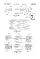
- FIG. 1is a top, front and left side perspective view of a grooved slider electrode for use with a resectoscope
- FIG. 2is a top view of a grooved slider shown in FIG. 1 having a treating surface formed of a plurality of spaced rails;
- FIG. 3is a front elevational view of a grooved slider shown in FIG. 1;
- FIG. 4is a right side elevational view of the grooved slider of FIG. 2;
- FIG. 5is a front elevational view of another embodiment of a grooved slider having raised rails in the form of substantially rectangular cross-section rails having a selected height and elongated slots formed therebetween;
- FIG. 6(a)is a right side elevational view of the grooved slider of FIG. 4;
- FIG. 6(b)is a right side elevational view of an eccentric grooved slider having a treating surface similar to that of the grooved slider of FIG. 5;
- FIG. 7is a front elevational view of another embodiment of a grooved slider having raised rails in the form of substantially triangular cross-section rails having a selected height and elongated slots formed therebetween;
- FIG. 8(a)is a right side elevational view of the grooved slider of FIG. 7;
- FIG. 8(b)is a right side elevational view of an eccentric grooved slider having a treating surface similar to that of the grooved slider of FIG. 8(a);
- FIG. 9is another embodiment of a grooved slider wherein the electrode is in the form of a sawtooth member having a plurality of spaced, triangular shaped slots having a selected depth forming a treating surface having at lease two spaced ridges;
- FIG. 10is a right side elevational view of the grooved slider of FIG. 9;
- FIG. 11is a front elevational view of another embodiment of a grooved slider having a treating surface in the form of single, elongated slot defining a trough having raised side rails;
- FIG. 12(a)is a right side elevational view of the grooved slider of FIG. 11;
- FIG. 12(b)is a right side elevational view of an eccentric grooved slider having a treatment surface similar to that of the grooved slider of FIG. 11;
- FIG. 13is a front elevational view of another embodiment of a grooved slider wherein the electrode is in the form of a plurality of spaced parallel teeth;
- FIG. 14is a right side elevational view of the grooved slider of FIG. 13;
- FIGS. 15, 16 and 17illustrate another embodiment of a grooved slider having a treating surface in the form of a plurality of spaced substantially parallel conically shaped teeth having a selected height and spaces formed therebetween.
- FIGS. 18, 19, 20(a) and 20(b)illustrate another embodiment of a grooved slider having a treating surface in the form of two sections wherein a first section has two parallel rails having selected heights and elongated slots formed therebetween and a second section has three parallel rails having a selected height and elongated slots formed therebetween;
- FIG. 21is a schematic diagram of an electrosurgical generator operatively connected to a resectoscope
- FIG. 22is a chart showing parameters for vaporization
- FIG. 23is a block diagram of a method for using the grooved slider electrode in a urological procedure.
- FIG. 24is a diagrammatic representation of a trough formed in a patient tissue using a grooved slider of the preferred embodiment.
- the structure of the electrodeis for use with a resectoscope.
- the electrode 20includes an electrode lead member 22 having an elongated conductor member 26 having a first end 30 and a second end 32.
- An insulative cover 34extends between the first end 30 and the second end 32.
- the first end 30has a protruding electrode 38 which is adapted to be electrically connected to an electrosurgical generator.
- the second end 32terminates in an active member or a loading member shown generally as 40.
- the active member 40has an electrode support member, shown generally as 42, operatively connected to the loading member 40.
- the electrode support member 42has an elongated semi-rigid bifurcated arm 46 which terminates in a conductive core 50 spaced a predetermined distance from the active member 40.
- the bifurcated arm 46has an insulative covering formed thereon except in the portion thereof which forms the conductive core 50.
- the electrode support member 42has a grooved slider 48 having a central opening 54 extending therethrough for fixedly mounting the grooved slider 48 on the conductive core 50.
- the electrode stabilizer 60 for stabilizing the grooved slideris proximate a distal region of a telescope mounted in a resectoscope working element. It is envisioned that the electrode 20 does not need the electrode stabilizer 60 in order to practice this invention.
- the distal end of a telescopeis removeably supported by stabilizer 60.
- the stabilizer 60has a pair of space resilient support arms 64 which define a hollowed out space 68 to receive a telescope.
- the stabilizer 60is made of a resilient and flexible dielectric material, generally an insulating material, and resiliently literally mount the electrode to a telescope and insulates the electrode 20 from a telescope.
- FIGS. 2, 3 and 4depict the preferred embodiment of a grooved slider 48 generally in the form of a planar base 58 having a support surface which includes a connecting member.
- the connecting memberhas a central opening 56 for receiving the conductive core 50 and for rigidly attaching the grooved slider to the conductive core 50.
- the grooved sliderhas a treating surface having a plurality of spaced raised rails 52.
- the typical depth of the rails 52would be in the order of 0.012 inches (3 mm) and the width of the slots therebetween would be in the order of 0.015 inches (4 mm).
- the diameter of the support basewould be in the order of 0.115 inches to about 0.160 inches (3 to 4.5 mm).
- FIG. 5illustrates another embodiment of a grooved slider 70 having a trapezial front view with a connecting member 72 at the top thereof and a treating surface located on the bottom thereof having raised rails 76.
- the treating surface raised rails 76are in the form of substantially rectangular cross-sectional rails having a selected height and having elongated slots 74 formed therebetween.
- Raised side rails 78are formed along the edges of the treating surface.
- the grooved slider 70has a central opening 80 which is adapted to receive and be fixedly attached to the conductive core 50 as shown in FIG. 1.
- FIG. 6(a)illustrates that the grooved slider 70 of FIG. 5 is symmetrical and has a central opening 80 which is adapted to be fixedly attached to the conductive core 50 as shown in FIG. 1.
- FIG. 6(b)illustrates a right side elevational view of an eccentric of a grooved slider similar to that of FIG. 5 which is shown as 70.
- the grooved sliderhas a top 72, a central opening 80 and a treating surface which is similar to that shown on FIG. 5.
- FIG. 7illustrates another embodiment of a grooved slider 90 raised rails in the form of substantially triangular cross-sectional rails having a selected height and having elongated slots 94 formed therebetween.
- Raised side rails 98are formed along the edges of the treating surface.
- the grooved slider 90has top 92 defining a central opening 100 which is adapted to receive and be fixedly attached to the conductive core 50 as shown in FIG. 1.
- FIG. 8(a)illustrates in a side elevational view the grooved slider 90 of FIG. 7.
- the grooved slider 90 as illustrated in FIG. 7is symmetrical and has a top 72 and a central opening 100.
- FIG. 8(b)illustrates a right side elevational view of an eccentric grooved slider 90 which is similar to that of FIG. 7.
- the grooved slider 90has a top 72, a central opening 100 and a treating surface which is similar to that shown in FIG. 7.
- FIGS. 9 and 10illustrate another embodiment of a grooved slider 110 wherein the electrode is in the form of a sawtooth member having a plurality of spaced, triangular shaped slots having a selected depth and vertex or ridge 106 forming a treating surface having at least two spaced ridges.
- Side conductors 104are electrically connected to leads 102 which form part of the bifurcated arm 42 illustrated in FIG. 1.
- FIG. 11illustrates another embodiment of a grooved slider, shown generally as 120, having a treating surface in the form of a single elongated slot 124 defining a trough having raised side rails 128.
- the grooved slider 120has a top 122 and an elongated opening 130 which extends axially through the grooved slider 120.
- the grooved slider 120is adapted to be fixedly mounted on the conductive core 50 illustrated in FIG. 1.
- FIG. 12(a)illustrates in a right wide elevational view that the grooved slider, shown generally as 120 of FIG. 5, is symmetrical and has a central opening 130 which is adapted to fixedly mount the grooved slider 120 to the conductive core 50 as shown in FIG. 1.
- FIG. 12(b)illustrates a right side elevational view of an eccentrical of a grooved slider similar to that of FIG. 11.
- the grooved slider 120has a top 122, a central opening 130 and a treating surface which is similar to that shown in FIG. 11.
- FIGS. 13 and 14illustrate another embodiment of a grooved slider 136 wherein the electrode is in the form of a plurality of spaced, parallel teeth 140 formed by coils of wire 140.
- the structure of the teeth and the slots forming a treating surface having at least two spaced ridgesis similar to the electrode described in FIGS. 9 and 10.
- FIGS. 15, 16 and 17illustrate another embodiment of a grooved slider 150 having a treating surface in the form of a plurality of spaced, substantially parallel conically shaped teeth 154 having a selected height and spaces 156 formed therebetween.
- the grooved slider 150has a connecting member having a top 72 and a central opening 158 which is adapted to receive and be fixedly attached to the conductive core 50 as shown in FIG. 1.
- FIGS. 18, 19, 20(a) and 20(b)illustrate another embodiment of a grooved slider 160 having a treating surface in the form of two sections 162 and 164.
- the first section 162has two parallel rails 168 having selected heights and elongated slots 170 formed therebetween.
- the second section 164has three parallel rails 176 having selected heights and elongated slots 180 formed therebetween.
- the grooved slider 160is mounted by the surface opposite to the treating surface to the conductive core 30 of FIG. 1.
- FIG. 21is a schematic diagram of an electrosurgical generator 190 which is operatively connected to a resectoscope 194 including a working element.
- the electrosurgical generator 190produces typical R.F. electrosurgical currents which may be a cutting current, a blend current or a loop current.
- typical R.F. electrosurgical currentsis set forth at pages 96 through 97 and page 100 of the Valleylab SSE4 Instruction Manual.
- the electrosurgical current from the electrosurgical generator 190is applied by the grooved slider electrode 20 and the grooved slider 48 to a patient tissue to be treated, shown by tissue 198.
- the dispersive electrode 202is electrically connected to an isolated terminal 206.
- the electrosurgical generator 190is electrically connected to the isolated terminal 206.
- the patient 196is part of the electrically conductive path.
- the areas of high concentration of R.F. electrosurgical current which form on the protruding ridges, such as, for example, ridges 52 of the grooved slider 48result in areas of increased current density which electrically interact with the tissue being treated.
- the grooved slider 48is moved gently over the tissue allowing the grooved slider 48 to move without much pressure, not unlike moving a hot knife through butter, vaporizing the tissue forming a trough therein. This is discussed further in connection with FIG. 24.
- the grooved slider 48functions as an active electrode while the patient grounding plate functions as a dispersive electrode.
- FIG. 22shows a table of parameters for vaporization using the teachings of the invention.
- the procedurecan be performed with the grooved slider in either air or liquid as a medium.
- airprovides less electrical resistance such that an electrosurgical voltage of about 200 volts and a power level of between 160 watts to 240 watts will provide the desired cutting action.
- An electrical surgical voltage of about 300 volts in airproduces charting resulting in a tissue layer having high resistance, which is undesirable.
- an electrosurgical voltage of about 300 volts and a power level of between 160 and 240 wattsproduces the desired cutting action while an electrosurgical voltage of about 400 volts to about 500 volts produces charring of the tissue.
- FIG. 23illustrates the steps of the method.
- the methodcomprises the steps of inserting a sheath, which may be an outer sheath for a continuous flow resectoscope (CFR), having a visual obturator into a urethra as shown by 210.
- CFRcontinuous flow resectoscope
- Step 214provides for inserting into a resectoscope working element a telescope and an electrode wherein the electrode has an electrode lead member includes an elongated conductor member having a first end and a second end with an insulative cover extended therebetween wherein said first end has a protruding electrode adapted to be electrically connected to an electrosurgical generator and wherein said second end terminates in an active member and having an electrode support having an elongated semi-rigid bifurcated arm terminating in a conductive core spaced a predetermined distance from the active member and wherein the electrode support member has a grooved slider having a central opening extending therethrough for rotatably mounting the grooved slider on the conductive core.
- Step 216provides for passing the resectoscope working element having the telescope and electrode mounted thereon into the outer sheath and visually positioning the grooved slider in the proximity of the tissue to be treated.
- Step 218provides for irrigating through the outer sheath the tissue to be treated with an irrigation fluid. However, this step is not required if a non-continuous flow resectoscope is used.
- Step 220provides for applying an electrosurgical cutting current to the grooved slider at a selected voltage level of between about 200 volts to about 300 volts.
- Step 220also provides for moving the grooved slider having an electrosurgical cutting current applied thereto over the tissue to be treated to vaporize the tissue.
- the method for treating prostate tissuecomprises the step of irrigating through an instrument the prostate tissue to be treated and applying a high electrosurgical cutting current to grooved slider at a selected voltage level of between about 200 volts to about 300 volts, and moving the grooved slider having the electrosurgical cutting current applied thereto over a selected portion of prostate tissue to be treated to vaporize the tissue and form a trough having a coagulation layer of treated tissue of at least 2 mm.
- FIG. 24is a pictorial representation of a tissue area shown by 230, such as a prostate, wherein the grooved slider 48 supported by bifurcated arm 46 has formed a crater or trough 196 having side walls 232.
- the velocity of movement of the grooved slider 48 in prostate tissueis approximately 5 mm/sec.
- the depth of the trough(height of sidewalls 232) is in the order of 3 mm.
- the R.F. electrosurgical settingcooperates with the raised ridges or protrusions to form areas of increased current densities which generate sufficient current flow at the appropriate voltage levels to vaporize the tissue.
- the tissue surrounding the vaporized tissuebecomes coagulated by the R.F. electrosurgical current at the boundary of the vaporized tissue resulting in a layer of necrosed tissue around the side walls 232 and trough 234.
- the thickness of the coagulated layeris in the order of about 1.5 mm to about 2 mm.
- Energy settingsin the range of 160 watts to about 250 watts is desired, with the preferred power settings to be about 200 watts.
- the electrode structurecould be designed for use in a gynecological procedure with a gynecological resectoscope for performing endometrial ablation of the uterus or debulking myomas.
Landscapes
- Health & Medical Sciences (AREA)
- Surgery (AREA)
- Engineering & Computer Science (AREA)
- Life Sciences & Earth Sciences (AREA)
- Biomedical Technology (AREA)
- Otolaryngology (AREA)
- Nuclear Medicine, Radiotherapy & Molecular Imaging (AREA)
- Plasma & Fusion (AREA)
- Physics & Mathematics (AREA)
- Heart & Thoracic Surgery (AREA)
- Medical Informatics (AREA)
- Molecular Biology (AREA)
- Animal Behavior & Ethology (AREA)
- General Health & Medical Sciences (AREA)
- Public Health (AREA)
- Veterinary Medicine (AREA)
- Surgical Instruments (AREA)
Abstract
Description
Claims (15)
Priority Applications (2)
| Application Number | Priority Date | Filing Date | Title |
|---|---|---|---|
| US08/312,957US5582610A (en) | 1994-09-30 | 1994-09-30 | Grooved slider electrode for a resectoscope |
| US08/762,168US6197025B1 (en) | 1994-09-30 | 1996-12-09 | Grooved slider electrode for a resectoscope |
Applications Claiming Priority (1)
| Application Number | Priority Date | Filing Date | Title |
|---|---|---|---|
| US08/312,957US5582610A (en) | 1994-09-30 | 1994-09-30 | Grooved slider electrode for a resectoscope |
Related Child Applications (1)
| Application Number | Title | Priority Date | Filing Date |
|---|---|---|---|
| US08/762,168Continuation-In-PartUS6197025B1 (en) | 1994-09-30 | 1996-12-09 | Grooved slider electrode for a resectoscope |
Publications (1)
| Publication Number | Publication Date |
|---|---|
| US5582610Atrue US5582610A (en) | 1996-12-10 |
Family
ID=23213758
Family Applications (1)
| Application Number | Title | Priority Date | Filing Date |
|---|---|---|---|
| US08/312,957Expired - LifetimeUS5582610A (en) | 1994-09-30 | 1994-09-30 | Grooved slider electrode for a resectoscope |
Country Status (1)
| Country | Link |
|---|---|
| US (1) | US5582610A (en) |
Cited By (71)
| Publication number | Priority date | Publication date | Assignee | Title |
|---|---|---|---|---|
| USD385351S (en)* | 1995-12-06 | 1997-10-21 | Northgate Technologies Incorporated | Tip portion of a resectoscope electrode |
| US5749870A (en)* | 1996-08-23 | 1998-05-12 | Nebl, Inc. | Electrode for coagulation and resection |
| US5766168A (en)* | 1996-01-11 | 1998-06-16 | Northgate Technologies, Inc. | Perforated resectoscope electrode assembly |
| WO1998027882A1 (en)* | 1996-12-20 | 1998-07-02 | Vandusseldorp Gregg A | Cutting loop for an electrocautery probe |
| US5782829A (en)* | 1995-12-06 | 1998-07-21 | Northgate Technologies Incorporated | Resectoscope electrode assembly and methods of use |
| WO1998033445A1 (en)* | 1997-02-05 | 1998-08-06 | Symbiosis Corporation | Single arm electrocautery probes and probes with upper and lower operating surfaces for use with a resectoscope |
| US5827274A (en)* | 1995-07-18 | 1998-10-27 | Richard Wolf Gmbh | Electrode for vaporizing tissue |
| USD401338S (en) | 1996-06-18 | 1998-11-17 | Northgate Technologies, Inc. | Tip of a resectoscope electrode assembly design |
| US5902300A (en)* | 1997-02-05 | 1999-05-11 | Symbiosis Corporation | Electrodes having upper and lower operating surfaces for electrocautery probes for use with a resectoscope |
| US5906615A (en)* | 1997-03-31 | 1999-05-25 | Femrx, Inc. | Serpentine ablation/coagulation electrode |
| US5938661A (en)* | 1997-02-05 | 1999-08-17 | Symbosis Corporation | Single arm electrocautery probes for use with a resectoscope |
| WO1999042042A1 (en)* | 1998-02-23 | 1999-08-26 | Vancaillie Thierry G | Desiccation electrode |
| US5944715A (en) | 1996-06-20 | 1999-08-31 | Gyrus Medical Limited | Electrosurgical instrument |
| US6004319A (en) | 1995-06-23 | 1999-12-21 | Gyrus Medical Limited | Electrosurgical instrument |
| EP0917482A4 (en)* | 1996-07-18 | 1999-12-22 | Arthrocare Corp | Shaped electrodes and methods for electrosurgical cutting and ablation |
| US6013076A (en) | 1996-01-09 | 2000-01-11 | Gyrus Medical Limited | Electrosurgical instrument |
| US6015406A (en) | 1996-01-09 | 2000-01-18 | Gyrus Medical Limited | Electrosurgical instrument |
| US6027501A (en) | 1995-06-23 | 2000-02-22 | Gyrus Medical Limited | Electrosurgical instrument |
| US6033400A (en)* | 1996-04-19 | 2000-03-07 | Circon Corporation | Shaped electrode for a resectoscope |
| US6032673A (en)* | 1994-10-13 | 2000-03-07 | Femrx, Inc. | Methods and devices for tissue removal |
| US6090106A (en) | 1996-01-09 | 2000-07-18 | Gyrus Medical Limited | Electrosurgical instrument |
| US6093186A (en) | 1996-12-20 | 2000-07-25 | Gyrus Medical Limited | Electrosurgical generator and system |
| US6152921A (en)* | 1995-12-22 | 2000-11-28 | Karl Storz Gmbh & Co. Kg | High frequency (HF) electrode for a HF instrument operating in monopolar mode |
| US6197025B1 (en)* | 1994-09-30 | 2001-03-06 | Circon Corporation | Grooved slider electrode for a resectoscope |
| US6210405B1 (en) | 1996-06-20 | 2001-04-03 | Gyrus Medical Limited | Under water treatment |
| WO2001026571A1 (en)* | 1999-10-14 | 2001-04-19 | Applied Medical Resources Incorporated | Electrosurgical snare |
| US6261286B1 (en) | 1995-06-23 | 2001-07-17 | Gyrus Medical Limited | Electrosurgical generator and system |
| US6277114B1 (en) | 1998-04-03 | 2001-08-21 | Gyrus Medical Limited | Electrode assembly for an electrosurical instrument |
| US6394949B1 (en) | 1998-10-05 | 2002-05-28 | Scimed Life Systems, Inc. | Large area thermal ablation |
| US6565561B1 (en) | 1996-06-20 | 2003-05-20 | Cyrus Medical Limited | Electrosurgical instrument |
| US6780180B1 (en) | 1995-06-23 | 2004-08-24 | Gyrus Medical Limited | Electrosurgical instrument |
| US20040254571A1 (en)* | 2003-01-31 | 2004-12-16 | Kobi Iki | Cartilage treatment probe |
| US20080015547A1 (en)* | 2005-07-14 | 2008-01-17 | Beisel Robert F | Stylet free flexible-tip epidural catheter and method of making |
| US20080077129A1 (en)* | 2006-09-27 | 2008-03-27 | Van Wyk Robert A | Electrosurgical Device Having Floating Potential Electrode and Adapted for Use With a Resectoscope |
| US7481807B2 (en) | 2002-02-12 | 2009-01-27 | Oratec Interventions, Inc. | Radiofrequency arthroscopic ablation device |
| US7678106B2 (en) | 2000-08-09 | 2010-03-16 | Halt Medical, Inc. | Gynecological ablation procedure and system |
| US20100331621A1 (en)* | 2009-06-30 | 2010-12-30 | Gyrus Acmi, Inc. | Bipolar resection device having simplified rotational control and better visualization |
| US20110015646A1 (en)* | 2009-07-17 | 2011-01-20 | North Richard B | Shaped electrode and dissecting tool |
| US20110212178A1 (en)* | 2009-09-24 | 2011-09-01 | Microvention, Inc. | Injectable Hydrogel Filaments For Biomedical Uses |
| US8066700B2 (en)* | 2003-01-31 | 2011-11-29 | Smith & Nephew, Inc. | Cartilage treatment probe |
| US8080009B2 (en) | 2005-07-01 | 2011-12-20 | Halt Medical Inc. | Radio frequency ablation device for the destruction of tissue masses |
| US8241276B2 (en) | 2007-11-14 | 2012-08-14 | Halt Medical Inc. | RF ablation device with jam-preventing electrical coupling member |
| US8251991B2 (en) | 2007-11-14 | 2012-08-28 | Halt Medical Inc. | Anchored RF ablation device for the destruction of tissue masses |
| US8512333B2 (en) | 2005-07-01 | 2013-08-20 | Halt Medical Inc. | Anchored RF ablation device for the destruction of tissue masses |
| USD709613S1 (en)* | 2012-11-07 | 2014-07-22 | Karl Storz Gmbh & Co. Kg | Cutting electrode |
| USD712032S1 (en)* | 2012-11-07 | 2014-08-26 | Karl Storz Gmbh & Co. Kg | Cutting electrode |
| US8882796B2 (en) | 2002-07-31 | 2014-11-11 | Microvention, Inc. | Three element coaxial vaso-occlusive device |
| US8906008B2 (en) | 2012-05-22 | 2014-12-09 | Covidien Lp | Electrosurgical instrument |
| USD724210S1 (en)* | 2013-09-02 | 2015-03-10 | Karl Storz Gmbh & Co. Kg | Bipolar cutting electrode |
| US8992521B2 (en) | 2010-04-22 | 2015-03-31 | Electromedical Associates, Llc | Flexible electrosurgical ablation and aspiration electrode with beveled active surface |
| US9011426B2 (en) | 2010-04-22 | 2015-04-21 | Electromedical Associates, Llc | Flexible electrosurgical ablation and aspiration electrode with beveled active surface |
| US9168084B2 (en) | 2010-05-11 | 2015-10-27 | Electromedical Associates, Llc | Brazed electrosurgical device |
| CN105232145A (en)* | 2015-11-18 | 2016-01-13 | 南京亿高微波系统工程有限公司 | Improved plasma resectoscope |
| US9259228B2 (en) | 2006-06-15 | 2016-02-16 | Microvention, Inc. | Embolization device constructed from expansile polymer |
| US9381278B2 (en) | 2012-04-18 | 2016-07-05 | Microvention, Inc. | Embolic devices |
| US9456823B2 (en) | 2011-04-18 | 2016-10-04 | Terumo Corporation | Embolic devices |
| US9486221B2 (en) | 2007-12-21 | 2016-11-08 | Microvision, Inc. | Hydrogel filaments for biomedical uses |
| USD773045S1 (en)* | 2015-02-09 | 2016-11-29 | Karl Storz Gmbh & Co. Kg | Cutting electrode |
| USD773046S1 (en)* | 2015-02-09 | 2016-11-29 | Karl Storz Gmbh & Co. Kg | Cutting electrode |
| USD783818S1 (en)* | 2015-05-11 | 2017-04-11 | Karl Storz Gmbh & Co. Kg | Electrode |
| US9643255B2 (en) | 2010-04-22 | 2017-05-09 | Electromedical Associates, Llc | Flexible electrosurgical ablation and aspiration electrode with beveled active surface |
| USD792972S1 (en)* | 2015-08-21 | 2017-07-25 | Karl Storz Gmbh & Co. Kg | Bipolar electrode |
| US9888954B2 (en) | 2012-08-10 | 2018-02-13 | Cook Medical Technologies Llc | Plasma resection electrode |
| US9993252B2 (en) | 2009-10-26 | 2018-06-12 | Microvention, Inc. | Embolization device constructed from expansile polymer |
| US10092663B2 (en) | 2014-04-29 | 2018-10-09 | Terumo Corporation | Polymers |
| US10124090B2 (en) | 2014-04-03 | 2018-11-13 | Terumo Corporation | Embolic devices |
| US10226533B2 (en) | 2014-04-29 | 2019-03-12 | Microvention, Inc. | Polymer filaments including pharmaceutical agents and delivering same |
| US10363086B2 (en) | 2014-10-31 | 2019-07-30 | Medtronic Advanced Energy Llc | Power monitoring circuitry and method for reducing leakage current in RF generators |
| US10639396B2 (en) | 2015-06-11 | 2020-05-05 | Microvention, Inc. | Polymers |
| USD943099S1 (en)* | 2019-08-28 | 2022-02-08 | Olympus Corporation | Bipolar cutting electrode |
| US12187387B2 (en) | 2009-04-30 | 2025-01-07 | Microvention, Inc. | Polymers |
Citations (10)
| Publication number | Priority date | Publication date | Assignee | Title |
|---|---|---|---|---|
| US642849A (en)* | 1899-11-27 | 1900-02-06 | Whitall Tatum & Co | Electrical massage instrument. |
| US4095601A (en)* | 1975-06-09 | 1978-06-20 | Aufranc Charles Walte | Electrotherapeutic apparatus |
| US4314559A (en)* | 1979-12-12 | 1982-02-09 | Corning Glass Works | Nonstick conductive coating |
| US4532924A (en)* | 1980-05-13 | 1985-08-06 | American Hospital Supply Corporation | Multipolar electrosurgical device and method |
| US4726370A (en)* | 1985-02-09 | 1988-02-23 | Olympus Optical Co., Ltd. | Resectoscope device |
| US4765331A (en)* | 1987-02-10 | 1988-08-23 | Circon Corporation | Electrosurgical device with treatment arc of less than 360 degrees |
| US4917082A (en)* | 1988-06-02 | 1990-04-17 | Circon Corporation | Resectoscope electrode |
| US5112330A (en)* | 1988-09-16 | 1992-05-12 | Olympus Optical Co., Ltd. | Resectoscope apparatus |
| US5196011A (en)* | 1990-10-15 | 1993-03-23 | Olympus Winter & Ibe Gmbh | Cutting electrode for medical resectoscope |
| US5395363A (en)* | 1993-06-29 | 1995-03-07 | Utah Medical Products | Diathermy coagulation and ablation apparatus and method |
- 1994
- 1994-09-30USUS08/312,957patent/US5582610A/ennot_activeExpired - Lifetime
Patent Citations (10)
| Publication number | Priority date | Publication date | Assignee | Title |
|---|---|---|---|---|
| US642849A (en)* | 1899-11-27 | 1900-02-06 | Whitall Tatum & Co | Electrical massage instrument. |
| US4095601A (en)* | 1975-06-09 | 1978-06-20 | Aufranc Charles Walte | Electrotherapeutic apparatus |
| US4314559A (en)* | 1979-12-12 | 1982-02-09 | Corning Glass Works | Nonstick conductive coating |
| US4532924A (en)* | 1980-05-13 | 1985-08-06 | American Hospital Supply Corporation | Multipolar electrosurgical device and method |
| US4726370A (en)* | 1985-02-09 | 1988-02-23 | Olympus Optical Co., Ltd. | Resectoscope device |
| US4765331A (en)* | 1987-02-10 | 1988-08-23 | Circon Corporation | Electrosurgical device with treatment arc of less than 360 degrees |
| US4917082A (en)* | 1988-06-02 | 1990-04-17 | Circon Corporation | Resectoscope electrode |
| US5112330A (en)* | 1988-09-16 | 1992-05-12 | Olympus Optical Co., Ltd. | Resectoscope apparatus |
| US5196011A (en)* | 1990-10-15 | 1993-03-23 | Olympus Winter & Ibe Gmbh | Cutting electrode for medical resectoscope |
| US5395363A (en)* | 1993-06-29 | 1995-03-07 | Utah Medical Products | Diathermy coagulation and ablation apparatus and method |
Non-Patent Citations (3)
| Title |
|---|
| The Use of the Resectoscope in Gynecology, Richard A Auhll, pp. 91 99, Biomedical Business International, Oct. 11, 1990.* |
| The Use of the Resectoscope in Gynecology, Richard A Auhll, pp. 91-99, Biomedical Business International, Oct. 11, 1990. |
| Transurethral Vaporization of the Prostrate (T.V.P.); New Horizons, Irving M. Bush, M.D., Edward Malters, MD and Janet Bush, RN; Poster Presentation; SMIT, Nov., 1993, Orlando, Florida.* |
Cited By (119)
| Publication number | Priority date | Publication date | Assignee | Title |
|---|---|---|---|---|
| US6197025B1 (en)* | 1994-09-30 | 2001-03-06 | Circon Corporation | Grooved slider electrode for a resectoscope |
| US6032673A (en)* | 1994-10-13 | 2000-03-07 | Femrx, Inc. | Methods and devices for tissue removal |
| US6416509B1 (en) | 1995-06-23 | 2002-07-09 | Gyrus Medical Limited | Electrosurgical generator and system |
| US6364877B1 (en) | 1995-06-23 | 2002-04-02 | Gyrus Medical Limited | Electrosurgical generator and system |
| US6056746A (en) | 1995-06-23 | 2000-05-02 | Gyrus Medical Limited | Electrosurgical instrument |
| US6780180B1 (en) | 1995-06-23 | 2004-08-24 | Gyrus Medical Limited | Electrosurgical instrument |
| US6027501A (en) | 1995-06-23 | 2000-02-22 | Gyrus Medical Limited | Electrosurgical instrument |
| US6174308B1 (en) | 1995-06-23 | 2001-01-16 | Gyrus Medical Limited | Electrosurgical instrument |
| US6004319A (en) | 1995-06-23 | 1999-12-21 | Gyrus Medical Limited | Electrosurgical instrument |
| US6293942B1 (en) | 1995-06-23 | 2001-09-25 | Gyrus Medical Limited | Electrosurgical generator method |
| US6261286B1 (en) | 1995-06-23 | 2001-07-17 | Gyrus Medical Limited | Electrosurgical generator and system |
| US6306134B1 (en) | 1995-06-23 | 2001-10-23 | Gyrus Medical Limited | Electrosurgical generator and system |
| US5827274A (en)* | 1995-07-18 | 1998-10-27 | Richard Wolf Gmbh | Electrode for vaporizing tissue |
| USD385351S (en)* | 1995-12-06 | 1997-10-21 | Northgate Technologies Incorporated | Tip portion of a resectoscope electrode |
| US5782829A (en)* | 1995-12-06 | 1998-07-21 | Northgate Technologies Incorporated | Resectoscope electrode assembly and methods of use |
| US6152921A (en)* | 1995-12-22 | 2000-11-28 | Karl Storz Gmbh & Co. Kg | High frequency (HF) electrode for a HF instrument operating in monopolar mode |
| US6234178B1 (en) | 1996-01-09 | 2001-05-22 | Gyrus Medical Limited | Electrosurgical instrument |
| US6090106A (en) | 1996-01-09 | 2000-07-18 | Gyrus Medical Limited | Electrosurgical instrument |
| US6013076A (en) | 1996-01-09 | 2000-01-11 | Gyrus Medical Limited | Electrosurgical instrument |
| US6015406A (en) | 1996-01-09 | 2000-01-18 | Gyrus Medical Limited | Electrosurgical instrument |
| US5766168A (en)* | 1996-01-11 | 1998-06-16 | Northgate Technologies, Inc. | Perforated resectoscope electrode assembly |
| US5980520A (en)* | 1996-01-16 | 1999-11-09 | Vancaillie; Thierry G. | Desiccation electrode |
| US6033400A (en)* | 1996-04-19 | 2000-03-07 | Circon Corporation | Shaped electrode for a resectoscope |
| USD401338S (en) | 1996-06-18 | 1998-11-17 | Northgate Technologies, Inc. | Tip of a resectoscope electrode assembly design |
| US6210405B1 (en) | 1996-06-20 | 2001-04-03 | Gyrus Medical Limited | Under water treatment |
| US5944715A (en) | 1996-06-20 | 1999-08-31 | Gyrus Medical Limited | Electrosurgical instrument |
| US6482202B1 (en) | 1996-06-20 | 2002-11-19 | Gyrus Medical Limited | Under water treatment |
| US6565561B1 (en) | 1996-06-20 | 2003-05-20 | Cyrus Medical Limited | Electrosurgical instrument |
| EP0917482A4 (en)* | 1996-07-18 | 1999-12-22 | Arthrocare Corp | Shaped electrodes and methods for electrosurgical cutting and ablation |
| US5749870A (en)* | 1996-08-23 | 1998-05-12 | Nebl, Inc. | Electrode for coagulation and resection |
| US6093186A (en) | 1996-12-20 | 2000-07-25 | Gyrus Medical Limited | Electrosurgical generator and system |
| US5919190A (en)* | 1996-12-20 | 1999-07-06 | Vandusseldorp; Gregg A. | Cutting loop for an electrocautery probe |
| WO1998027882A1 (en)* | 1996-12-20 | 1998-07-02 | Vandusseldorp Gregg A | Cutting loop for an electrocautery probe |
| US6132428A (en)* | 1996-12-20 | 2000-10-17 | Vandusseldorp; Gregg A. | Cutting loop for an electrocautery probe |
| WO1998033445A1 (en)* | 1997-02-05 | 1998-08-06 | Symbiosis Corporation | Single arm electrocautery probes and probes with upper and lower operating surfaces for use with a resectoscope |
| US5902300A (en)* | 1997-02-05 | 1999-05-11 | Symbiosis Corporation | Electrodes having upper and lower operating surfaces for electrocautery probes for use with a resectoscope |
| US5938661A (en)* | 1997-02-05 | 1999-08-17 | Symbosis Corporation | Single arm electrocautery probes for use with a resectoscope |
| US5906615A (en)* | 1997-03-31 | 1999-05-25 | Femrx, Inc. | Serpentine ablation/coagulation electrode |
| WO1999042042A1 (en)* | 1998-02-23 | 1999-08-26 | Vancaillie Thierry G | Desiccation electrode |
| GB2350303A (en)* | 1998-02-23 | 2000-11-29 | Thierry G Vancaillie | Desiccation electrode |
| GB2350303B (en)* | 1998-02-23 | 2002-07-17 | Thierry G Vancaillie | Desiccation electrode |
| US6277114B1 (en) | 1998-04-03 | 2001-08-21 | Gyrus Medical Limited | Electrode assembly for an electrosurical instrument |
| US6394949B1 (en) | 1998-10-05 | 2002-05-28 | Scimed Life Systems, Inc. | Large area thermal ablation |
| US6932812B2 (en) | 1998-10-05 | 2005-08-23 | Scimed Life Systems, Inc. | Large area thermal ablation |
| US20100256632A1 (en)* | 1998-10-05 | 2010-10-07 | Boston Scientific Scimed, Inc. | Large area thermal ablation |
| US7749159B2 (en) | 1998-10-05 | 2010-07-06 | Boston Scientific Scimed, Inc. | Large area thermal ablation |
| WO2001026571A1 (en)* | 1999-10-14 | 2001-04-19 | Applied Medical Resources Incorporated | Electrosurgical snare |
| US7678106B2 (en) | 2000-08-09 | 2010-03-16 | Halt Medical, Inc. | Gynecological ablation procedure and system |
| US7481807B2 (en) | 2002-02-12 | 2009-01-27 | Oratec Interventions, Inc. | Radiofrequency arthroscopic ablation device |
| US8882796B2 (en) | 2002-07-31 | 2014-11-11 | Microvention, Inc. | Three element coaxial vaso-occlusive device |
| US8066700B2 (en)* | 2003-01-31 | 2011-11-29 | Smith & Nephew, Inc. | Cartilage treatment probe |
| US8377058B2 (en) | 2003-01-31 | 2013-02-19 | Smith & Nephew, Inc. | Cartilage treatment probe |
| AU2004291023B2 (en)* | 2003-01-31 | 2010-03-04 | Smith & Nephew, Inc. | Cartilage treatment probe |
| US20040254571A1 (en)* | 2003-01-31 | 2004-12-16 | Kobi Iki | Cartilage treatment probe |
| US7951142B2 (en)* | 2003-01-31 | 2011-05-31 | Smith & Nephew, Inc. | Cartilage treatment probe |
| US20110230879A1 (en)* | 2003-01-31 | 2011-09-22 | Smith & Nephew, Inc. | Cartilage treatment probe |
| US8500734B2 (en) | 2003-01-31 | 2013-08-06 | Smith & Nephew, Inc. | Cartilage treatment probe |
| US8512333B2 (en) | 2005-07-01 | 2013-08-20 | Halt Medical Inc. | Anchored RF ablation device for the destruction of tissue masses |
| US10828088B2 (en) | 2005-07-01 | 2020-11-10 | Acessa Health Inc. | Radio frequency ablation device for the destruction of tissue masses |
| US8080009B2 (en) | 2005-07-01 | 2011-12-20 | Halt Medical Inc. | Radio frequency ablation device for the destruction of tissue masses |
| US7695466B2 (en)* | 2005-07-14 | 2010-04-13 | Beisel Robert F | Stylet free flexible-tip epidural catheter and method of making |
| US20080015547A1 (en)* | 2005-07-14 | 2008-01-17 | Beisel Robert F | Stylet free flexible-tip epidural catheter and method of making |
| US10499925B2 (en) | 2006-06-15 | 2019-12-10 | Microvention, Inc. | Embolization device constructed from expansile polymer |
| US10226258B2 (en) | 2006-06-15 | 2019-03-12 | Microvention, Inc. | Embolization device constructed from expansile polymer |
| US9451963B2 (en) | 2006-06-15 | 2016-09-27 | Microvention, Inc. | Embolization device constructed from expansile polymer |
| US9724103B2 (en) | 2006-06-15 | 2017-08-08 | Microvention, Inc. | Embolization device constructed from expansile polymer |
| US9877731B2 (en) | 2006-06-15 | 2018-01-30 | Microvention, Inc. | Embolization device constructed from expansile polymer |
| US11185336B2 (en) | 2006-06-15 | 2021-11-30 | Microvention, Inc. | Embolization device constructed from expansile polymer |
| US11160557B2 (en) | 2006-06-15 | 2021-11-02 | Microvention, Inc. | Embolization device constructed from expansile polymer |
| US9259228B2 (en) | 2006-06-15 | 2016-02-16 | Microvention, Inc. | Embolization device constructed from expansile polymer |
| US8486064B2 (en) | 2006-09-27 | 2013-07-16 | Electromedical Associates Llc | Electrosurgical device having floating-potential electrode and curvilinear profile |
| US8177784B2 (en)* | 2006-09-27 | 2012-05-15 | Electromedical Associates, Llc | Electrosurgical device having floating potential electrode and adapted for use with a resectoscope |
| US8790340B2 (en) | 2006-09-27 | 2014-07-29 | Electromedical Associates, Llc | Electrosurgical device having floating-potential electrode for obstruction removal |
| US20080077129A1 (en)* | 2006-09-27 | 2008-03-27 | Van Wyk Robert A | Electrosurgical Device Having Floating Potential Electrode and Adapted for Use With a Resectoscope |
| US8348944B2 (en) | 2006-09-27 | 2013-01-08 | Electromedical Associates, Llc | Electrosurgical device having floating-potential electrode and bubble trap |
| US8251991B2 (en) | 2007-11-14 | 2012-08-28 | Halt Medical Inc. | Anchored RF ablation device for the destruction of tissue masses |
| US8241276B2 (en) | 2007-11-14 | 2012-08-14 | Halt Medical Inc. | RF ablation device with jam-preventing electrical coupling member |
| US10194915B2 (en) | 2007-12-21 | 2019-02-05 | Microvention, Inc. | Implantation devices including hydrogel filaments |
| US9486221B2 (en) | 2007-12-21 | 2016-11-08 | Microvision, Inc. | Hydrogel filaments for biomedical uses |
| US12187387B2 (en) | 2009-04-30 | 2025-01-07 | Microvention, Inc. | Polymers |
| US20100331621A1 (en)* | 2009-06-30 | 2010-12-30 | Gyrus Acmi, Inc. | Bipolar resection device having simplified rotational control and better visualization |
| US8685040B2 (en) | 2009-07-17 | 2014-04-01 | Richard B. North | Shaped electrode and dissecting tool |
| US20110015646A1 (en)* | 2009-07-17 | 2011-01-20 | North Richard B | Shaped electrode and dissecting tool |
| WO2011009037A3 (en)* | 2009-07-17 | 2014-03-20 | North Richard B | Shaped electrode and dissecting tool |
| US20110212178A1 (en)* | 2009-09-24 | 2011-09-01 | Microvention, Inc. | Injectable Hydrogel Filaments For Biomedical Uses |
| US9114200B2 (en) | 2009-09-24 | 2015-08-25 | Microvention, Inc. | Injectable hydrogel filaments for biomedical uses |
| US9993252B2 (en) | 2009-10-26 | 2018-06-12 | Microvention, Inc. | Embolization device constructed from expansile polymer |
| US8992521B2 (en) | 2010-04-22 | 2015-03-31 | Electromedical Associates, Llc | Flexible electrosurgical ablation and aspiration electrode with beveled active surface |
| US9011426B2 (en) | 2010-04-22 | 2015-04-21 | Electromedical Associates, Llc | Flexible electrosurgical ablation and aspiration electrode with beveled active surface |
| US9643255B2 (en) | 2010-04-22 | 2017-05-09 | Electromedical Associates, Llc | Flexible electrosurgical ablation and aspiration electrode with beveled active surface |
| US9168084B2 (en) | 2010-05-11 | 2015-10-27 | Electromedical Associates, Llc | Brazed electrosurgical device |
| US9456823B2 (en) | 2011-04-18 | 2016-10-04 | Terumo Corporation | Embolic devices |
| US9381278B2 (en) | 2012-04-18 | 2016-07-05 | Microvention, Inc. | Embolic devices |
| US9526569B2 (en) | 2012-05-22 | 2016-12-27 | Covidien Lp | Electrosurgical instrument |
| US8906008B2 (en) | 2012-05-22 | 2014-12-09 | Covidien Lp | Electrosurgical instrument |
| US9974606B2 (en) | 2012-05-22 | 2018-05-22 | Covidien Lp | Electrosurgical instrument |
| US9198721B2 (en) | 2012-05-22 | 2015-12-01 | Covidien Lp | Electrosurgical instrument |
| US9888954B2 (en) | 2012-08-10 | 2018-02-13 | Cook Medical Technologies Llc | Plasma resection electrode |
| USD712032S1 (en)* | 2012-11-07 | 2014-08-26 | Karl Storz Gmbh & Co. Kg | Cutting electrode |
| USD709613S1 (en)* | 2012-11-07 | 2014-07-22 | Karl Storz Gmbh & Co. Kg | Cutting electrode |
| USD724210S1 (en)* | 2013-09-02 | 2015-03-10 | Karl Storz Gmbh & Co. Kg | Bipolar cutting electrode |
| US10124090B2 (en) | 2014-04-03 | 2018-11-13 | Terumo Corporation | Embolic devices |
| US10946100B2 (en) | 2014-04-29 | 2021-03-16 | Microvention, Inc. | Polymers including active agents |
| US10092663B2 (en) | 2014-04-29 | 2018-10-09 | Terumo Corporation | Polymers |
| US10226533B2 (en) | 2014-04-29 | 2019-03-12 | Microvention, Inc. | Polymer filaments including pharmaceutical agents and delivering same |
| US10524851B2 (en) | 2014-10-31 | 2020-01-07 | Medtronic Advanced Energy Llc | Fingerswitch circuitry to reduce RF leakage current |
| US10405915B2 (en) | 2014-10-31 | 2019-09-10 | Medtronic Advanced Energy Llc | RF output stage switching mechanism |
| US10363086B2 (en) | 2014-10-31 | 2019-07-30 | Medtronic Advanced Energy Llc | Power monitoring circuitry and method for reducing leakage current in RF generators |
| US11426228B2 (en) | 2014-10-31 | 2022-08-30 | Medtronic Advanced Energy Llc | RF output stage switching mechanism |
| US11399885B2 (en) | 2014-10-31 | 2022-08-02 | Medtronic Advanced Energy Llc | Power monitoring circuitry and method for reducing leakage current in RF generators |
| USD773046S1 (en)* | 2015-02-09 | 2016-11-29 | Karl Storz Gmbh & Co. Kg | Cutting electrode |
| USD773045S1 (en)* | 2015-02-09 | 2016-11-29 | Karl Storz Gmbh & Co. Kg | Cutting electrode |
| USD783818S1 (en)* | 2015-05-11 | 2017-04-11 | Karl Storz Gmbh & Co. Kg | Electrode |
| US10639396B2 (en) | 2015-06-11 | 2020-05-05 | Microvention, Inc. | Polymers |
| US11759547B2 (en) | 2015-06-11 | 2023-09-19 | Microvention, Inc. | Polymers |
| USD792972S1 (en)* | 2015-08-21 | 2017-07-25 | Karl Storz Gmbh & Co. Kg | Bipolar electrode |
| CN105232145B (en)* | 2015-11-18 | 2017-05-17 | 南京亿高微波系统工程有限公司 | Improved plasma resectoscope |
| CN105232145A (en)* | 2015-11-18 | 2016-01-13 | 南京亿高微波系统工程有限公司 | Improved plasma resectoscope |
| USD943099S1 (en)* | 2019-08-28 | 2022-02-08 | Olympus Corporation | Bipolar cutting electrode |
Similar Documents
| Publication | Publication Date | Title |
|---|---|---|
| US5582610A (en) | Grooved slider electrode for a resectoscope | |
| US6197025B1 (en) | Grooved slider electrode for a resectoscope | |
| US5599349A (en) | V shaped grooved roller electrode for a resectoscope | |
| US5669906A (en) | Grooved roller electrode for a resectoscope | |
| US6033400A (en) | Shaped electrode for a resectoscope | |
| US8348944B2 (en) | Electrosurgical device having floating-potential electrode and bubble trap | |
| US5080660A (en) | Electrosurgical electrode | |
| EP0957795B1 (en) | Electro-surgical tissue removal | |
| US6395001B1 (en) | Electrosurgical electrode for wedge resection | |
| US6749608B2 (en) | Adenoid curette electrosurgical probe | |
| CA2304737C (en) | Apparatus for electro-surgical tissue removal | |
| US5683387A (en) | Electrosurgical electrode for skin grafting | |
| US6832998B2 (en) | Surgical instrument | |
| US5571101A (en) | Electrosurgical electrode for DCR surgical procedure | |
| US6921399B2 (en) | High efficiency electrosurgery probe | |
| US6796982B2 (en) | Instant ignition electrosurgical probe and method for electrosurgical cutting and ablation | |
| JP2000511077A (en) | Electrosurgical instrument and method of using the same | |
| EP1041933A1 (en) | Systems and methods for electrosurgical treatment of the skin | |
| US5741250A (en) | Electrosurgical instrument for ear surgery | |
| US20090234349A1 (en) | Bipolar electrosurgical probe for use with conductive irrigation fluids | |
| JP2000513970A (en) | Selectively insulated electrodes and methods of using such electrodes in hollow viscous tissue portions filled with physiological fluid | |
| JPH1043197A (en) | Electrode for electric operation | |
| JP2006006692A (en) | Electric surgical probe for resecting adenoids | |
| JPH0324219B2 (en) | ||
| CA2559942A1 (en) | Electro-surgical tissue removal |
Legal Events
| Date | Code | Title | Description |
|---|---|---|---|
| AS | Assignment | Owner name:CIRCON CORPORATION, CALIFORNIA Free format text:ASSIGNMENT OF ASSIGNORS INTEREST;ASSIGNORS:GROSSI, BENEDETTO;QUINT, ROBERT;REEL/FRAME:007151/0853 Effective date:19940928 | |
| STCF | Information on status: patent grant | Free format text:PATENTED CASE | |
| FPAY | Fee payment | Year of fee payment:4 | |
| AS | Assignment | Owner name:CHASE MANHATTAN BANK, THE, AS COLLATERAL AGENT, NE Free format text:SECURITY AGREEMENT;ASSIGNOR:CIRCON CORPORATION;REEL/FRAME:011122/0530 Effective date:19991112 | |
| AS | Assignment | Owner name:ACMI CORPORATION, MASSACHUSETTS Free format text:CHANGE OF NAME;ASSIGNOR:CIRCON CORPORATION;REEL/FRAME:013295/0416 Effective date:20011227 | |
| AS | Assignment | Owner name:ANTARES CAPITAL CORPORATION, AS AGENT, ILLINOIS Free format text:SECURITY INTEREST;ASSIGNOR:ACMI CORPORATION;REEL/FRAME:014815/0179 Effective date:20031219 Owner name:CIRCON CORPORATION, MASSACHUSETTS Free format text:RELEASE BY SECURED PARTY;ASSIGNOR:JPMORGAN CHASE BANK, AS COLLATERAL AGENT (F/K/A THE CHASE MANHATTAN BANK);REEL/FRAME:015592/0392 Effective date:20031219 | |
| FPAY | Fee payment | Year of fee payment:8 | |
| AS | Assignment | Owner name:ACMI CORPORATION, MASSACHUSETTS Free format text:RELASE OF SECURITY AGREEMENT;ASSIGNOR:ANTARES CAPITAL CORPORATION;REEL/FRAME:016309/0574 Effective date:20050721 | |
| AS | Assignment | Owner name:THE GOVERNOR AND COMPANY OF THE BANK OF SCOTLAND, Free format text:SECURITY AGREEMENT;ASSIGNOR:ACMI CORPORATION;REEL/FRAME:016418/0218 Effective date:20050804 | |
| FPAY | Fee payment | Year of fee payment:12 | |
| AS | Assignment | Owner name:GYRUS ACMI, INC., MASSACHUSETTS Free format text:CHANGE OF NAME;ASSIGNOR:ACMI CORPORATION;REEL/FRAME:024755/0110 Effective date:20070110 | |
| AS | Assignment | Owner name:GYRUS ACMI, INC., MASSACHUSETTS Free format text:ASSIGNMENT OF ASSIGNORS INTEREST;ASSIGNOR:BANK OF SCOTLAND;REEL/FRAME:030422/0113 Effective date:20130419 |