US5582479A - Dual reflector high bay lighting system - Google Patents
Dual reflector high bay lighting systemDownload PDFInfo
- Publication number
- US5582479A US5582479AUS08/396,567US39656795AUS5582479AUS 5582479 AUS5582479 AUS 5582479AUS 39656795 AUS39656795 AUS 39656795AUS 5582479 AUS5582479 AUS 5582479A
- Authority
- US
- United States
- Prior art keywords
- reflector
- lamp
- auxiliary reflector
- set forth
- auxiliary
- Prior art date
- Legal status (The legal status is an assumption and is not a legal conclusion. Google has not performed a legal analysis and makes no representation as to the accuracy of the status listed.)
- Expired - Lifetime
Links
- 230000009977dual effectEffects0.000titleclaimsabstractdescription20
- 238000009420retrofittingMethods0.000claimsdescription3
- 230000003247decreasing effectEffects0.000claimsdescription2
- 238000005286illuminationMethods0.000claimsdescription2
- 229910001507metal halideInorganic materials0.000description12
- 150000005309metal halidesChemical class0.000description12
- 238000009826distributionMethods0.000description11
- 238000009434installationMethods0.000description8
- 238000005259measurementMethods0.000description7
- 239000012141concentrateSubstances0.000description3
- 230000007423decreaseEffects0.000description3
- 239000000428dustSubstances0.000description3
- 239000000463materialSubstances0.000description3
- 238000004378air conditioningMethods0.000description2
- 230000000694effectsEffects0.000description2
- 229910052751metalInorganic materials0.000description2
- 239000002184metalSubstances0.000description2
- 238000005057refrigerationMethods0.000description2
- 238000009827uniform distributionMethods0.000description2
- DGAQECJNVWCQMB-PUAWFVPOSA-MIlexoside XXIXChemical compoundC[C@@H]1CC[C@@]2(CC[C@@]3(C(=CC[C@H]4[C@]3(CC[C@@H]5[C@@]4(CC[C@@H](C5(C)C)OS(=O)(=O)[O-])C)C)[C@@H]2[C@]1(C)O)C)C(=O)O[C@H]6[C@@H]([C@H]([C@@H]([C@H](O6)CO)O)O)O.[Na+]DGAQECJNVWCQMB-PUAWFVPOSA-M0.000description1
- 208000002847Surgical WoundDiseases0.000description1
- 229910052782aluminiumInorganic materials0.000description1
- XAGFODPZIPBFFR-UHFFFAOYSA-NaluminiumChemical compound[Al]XAGFODPZIPBFFR-UHFFFAOYSA-N0.000description1
- 239000003086colorantSubstances0.000description1
- 238000001816coolingMethods0.000description1
- 238000005265energy consumptionMethods0.000description1
- 239000011521glassSubstances0.000description1
- 238000004519manufacturing processMethods0.000description1
- 238000012986modificationMethods0.000description1
- 230000004048modificationEffects0.000description1
- 230000000630rising effectEffects0.000description1
- 238000007493shaping processMethods0.000description1
- 229910052708sodiumInorganic materials0.000description1
- 239000011734sodiumSubstances0.000description1
- 238000006467substitution reactionMethods0.000description1
Images


Classifications
- F—MECHANICAL ENGINEERING; LIGHTING; HEATING; WEAPONS; BLASTING
- F21—LIGHTING
- F21V—FUNCTIONAL FEATURES OR DETAILS OF LIGHTING DEVICES OR SYSTEMS THEREOF; STRUCTURAL COMBINATIONS OF LIGHTING DEVICES WITH OTHER ARTICLES, NOT OTHERWISE PROVIDED FOR
- F21V17/00—Fastening of component parts of lighting devices, e.g. shades, globes, refractors, reflectors, filters, screens, grids or protective cages
- F21V17/02—Fastening of component parts of lighting devices, e.g. shades, globes, refractors, reflectors, filters, screens, grids or protective cages with provision for adjustment
- F—MECHANICAL ENGINEERING; LIGHTING; HEATING; WEAPONS; BLASTING
- F21—LIGHTING
- F21S—NON-PORTABLE LIGHTING DEVICES; SYSTEMS THEREOF; VEHICLE LIGHTING DEVICES SPECIALLY ADAPTED FOR VEHICLE EXTERIORS
- F21S8/00—Lighting devices intended for fixed installation
- F21S8/04—Lighting devices intended for fixed installation intended only for mounting on a ceiling or the like overhead structures
- F—MECHANICAL ENGINEERING; LIGHTING; HEATING; WEAPONS; BLASTING
- F21—LIGHTING
- F21V—FUNCTIONAL FEATURES OR DETAILS OF LIGHTING DEVICES OR SYSTEMS THEREOF; STRUCTURAL COMBINATIONS OF LIGHTING DEVICES WITH OTHER ARTICLES, NOT OTHERWISE PROVIDED FOR
- F21V14/00—Controlling the distribution of the light emitted by adjustment of elements
- F21V14/04—Controlling the distribution of the light emitted by adjustment of elements by movement of reflectors
- F—MECHANICAL ENGINEERING; LIGHTING; HEATING; WEAPONS; BLASTING
- F21—LIGHTING
- F21V—FUNCTIONAL FEATURES OR DETAILS OF LIGHTING DEVICES OR SYSTEMS THEREOF; STRUCTURAL COMBINATIONS OF LIGHTING DEVICES WITH OTHER ARTICLES, NOT OTHERWISE PROVIDED FOR
- F21V7/00—Reflectors for light sources
- F21V7/0025—Combination of two or more reflectors for a single light source
Definitions
- This inventionrelates to an dual reflector high bay lighting system or luminaire having a main reflector and an auxiliary reflector which distributes the light in a certain way to direct a first predetermined amount of light onto the floor or work area and a second predetermined amount of light above the work area.
- the subject inventionincreases the efficiency of the lighting system so that a fixture with a high intensity discharge lamp of lower wattage can be used to get substantially equal or greater lighting on the work area.
- a fixture in accordance with this inventionwhich uses the same wattage lamp as a conventional fixture will provide a substantially greater amount of light on the work area.
- the inventionincludes a luminaire having a vertically oriented high intensity discharge lamp, a main reflector, and an auxiliary reflector mounted within the main reflector and movable vertically relative to the lamp for concentrating light in a first work area beneath the luminaire and providing a certain amount of light outside or above the first area.
- the inventionalso relates to an auxiliary reflector and bracket assembly for retrofitting conventional fixtures, and a retrofit kit for retrofitting conventional fixtures of a specific wattage, to dual reflector systems of lesser wattage.
- High bay lighting fixturesare typically used in warehouses and manufacturing plants. Such lights are generally referred to as high intensity discharge (HID) lights or gaseous discharge lights.
- HIDhigh intensity discharge
- Conventional high bay lighting fixturesdirect all of the light equally leaving the areas closest to the fixture too bright and the working areas furthest from the fixture too dim.
- light fixtureswill be between 15 to 65 feet above the floor. Most light is usually required at the working surface or floor level, not at the top of the storage racks or near the ceiling. However, the storage racks require sufficient lighting to enable workers operating fork lifts to have sufficient visibility to remove products from the racks and to store products in the racks.
- a fixture of higher wattagemust be used.
- HID lighting systemstypically use 400 watt and 1,000 watt luminaires for such installations.
- the subject inventionpermits the 400 watt luminaires to be replaced with 250 watt luminaires, and in some instances, 150 watt luminaires, and the 1,000 watt luminaires to be replaced by 400 watt luminaires.
- the amount of foot candles measured at the floor levelis substantially the same, or greater, while the lighting at the top of the racks may be reduced, but is still more than sufficient for workers to be able to function.
- the energy savings resulting from use of the lower wattage lampsis typically between 40-65%.
- Henderson Jr., et al U.S. Pat. No. 4,173,037discloses a luminaire lamp support device in which the lamp socket is adjustably mounted on a bracket for adjustment of the socket along a substantially vertical axis. This enables adjustment of the lamp to different positions to obtain various light distribution patterns.
- the lamphas an outer reflector and an asymmetric inner reflector which is mounted for rotational adjustment about the vertical axis of the luminaire for producing asymmetric distribution of reflected light.
- Sholtz U.S. Pat. No. 5,178,452discloses an operating theater lamp with a main reflector which illuminates the area of operation and an auxiliary reflector having an outer diameter which corresponds approximately to the inner diameter of the main reflector and which is arranged inside the main reflector to deflect a part of the light beam at a steeper angle into the bottom of a surgical wound.
- Wijbenga, et al U.S. Pat. No. 5,251,116discloses a luminaire for creating a primary beam and a secondary beam.
- Compton U.S. Pat. No. 4,231,080discloses a luminaire having at least three stack reflector members.
- Cochran U.S. Pat. No. 1,286,535discloses a lighting fixture having a main reflector and a stationary auxiliary reflector.
- the present inventionfills a need for an energy efficient high bay lighting fixture or luminaire which enables fixtures having lamps of reduced wattage to be used to replace higher wattage lamps and fixtures thereby conserving significant amounts of energy. Typically, the replacement of a 400 watt luminaire with a 250 watt luminaire will result in an approximately 40% or greater savings in energy.
- the present inventionrelates to a luminaire having a high intensity or gaseous discharge lamp which is mounted with the base up in a substantially vertical position. An auxiliary reflector is mounted to the luminaire for movement relative to the lamp and the main reflector.
- the auxiliary reflectoris adjustable along the longitudinal axis of the lamp so that a substantial amount of light is reflected from the auxiliary reflector onto a first predetermined area while a smaller amount of light is reflected from the main reflector onto a second predetermined area outside the first area or onto the racks or stacked merchandise which is positioned closer to the luminaire.
- the first predetermined areais an area substantially larger than the outer diameter of the main reflector. It is typically an area that is equal to or greater than the width of an aisle and usually averages ten to fourteen feet in diameter.
- an auxiliary reflectoris mounted to a bracket assembly which is clamped to the lamp socket of a luminaire.
- the auxiliary reflectorfits within the main reflector of the luminaire and is adjustable vertically to concentrate a substantial portion of light emanating from the lamp onto a first area of work surface. The remainder of the light is reflected from the main reflector onto the racks or onto a second area outside of the first area.
- a retrofit kitis provided to retrofit HID fixtures of a first wattage to convert them into a HID fixture of a second lower wattage having an auxiliary reflector in accordance with this invention.
- the retrofit kittypically includes an auxiliary reflector and bracket assembly, a ballast suitable for an HID lamp of lower wattage and, in some cases, the lower wattage lamp itself.
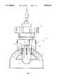
- FIG. 1is a side elevational view of a luminaire in accordance with this invention with the main reflector and auxiliary reflector both partially broken away.
- FIG. 2is a side elevational view with the main reflector broken away illustrating an alternative embodiment of the subject invention.
- FIG. 3is a top plan view of the auxiliary reflector and bracket shown in the FIG. 2 luminaire.
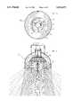
- FIG. 4is a side elevational view of a luminaire in accordance with this invention with the main and auxiliary reflectors partially broken away to illustrate the distribution of light achieved in accordance with this invention.
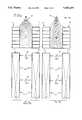
- FIG. 5Ais a side elevational view illustrating an aisle and a pair of racks alongside the aisle in a warehouse with a 400 watt metal halide lighting system installed illustrating the distribution of light for the prior art.
- FIG. 5Bis a side elevational view illustrating an aisle and a pair of racks alongside the aisle in a warehouse with a 400 watt metal halide lighting system illustrating the distribution of light in accordance with the subject invention.
- FIG. 6Ais a diagrammatic representation illustrating an aisle and a pair of racks alongside in a warehouse with a 400 watt metal halide lighting system illustrating the distribution of light at the working surface for the prior art shown in FIG. 5 A.
- FIG. 6Bis a diagrammatic representation illustrating an aisle and a pair of racks along side the aisle in a warehouse with a 400 watt metal halide lighting system in accordance with this invention illustrating the distribution of light at the working surface using the subject invention.
- FIG. 7Ais a diagrammatic representation illustrating an aisle and racks along the sides of the aisle in a warehouse with a 250 metal halide lighting system illustrating the distribution of light at the work surface for the prior art.
- FIG. 7Bis a diagrammatic representation illustrating an aisle and racks along the sides of the aisle in a warehouse with a 250 watt metal halide lighting system in accordance with this invention illustrating the distribution of light at the work surface using the subject invention.
- FIG. 1a luminaire generally designated as 10 having a casing 12 which contains the ballast (not shown) and a high intensity discharge lamp 14 which is mounted vertically with its base up into a socket 16.
- the casinghas a bracket assembly 17 connected thereto which has a pair of downwardly extending legs 18.
- the legs 18each have a short inwardly projecting horizontal section 19 which fits into a slot 20 in a main reflector 21.
- the main reflector 21may also be fastened to the bracket 17 in other ways conventional in the art.
- the bracket assembly 17is adjustable by a slot and screw arrangement at 15 to permit initial adjustment of the distribution of light from the main reflector 21.
- auxiliary reflector 22is mounted for movement relative to the main reflector 21 and lamp 14 by any number of suitable attachment means.
- the main reflector 21has two or more threaded members 23, such as internally threaded rivets, mounted in the top thereof. While a threaded member 23 is shown, it is apparent that it need not be inserted into the main reflector. If the upper surface of the reflector is thick enough, a hole could be drilled and tapped to receive a screw or bolt. Alternatively, a wing nut, nut or other threaded member could rest on or be secured to the top of the main reflector 21.
- a spring 26, or other biasing means,could be used to maintain the desired spacing between auxiliary reflector 22 and main reflector 21.
- a nutcould be threaded on the fastener 24 and fixed down on top of the auxiliary reflector in place of using a spring.
- the use of the springmerely facilitates installation and adjustment of the auxiliary reflector.
- the threaded portions of the fastenersmay be marked with lines or colors to permit the electrician or installer to evenly adjust the fasteners so that the top of the auxiliary reflector 22 is parallel to and evenly spaced from the top of main reflector 21.
- Every gaseous discharge lamphas an arc tube therein which is designated by the dotted lines 27 in the lamp 14.
- the adjustability of the auxiliary reflector 22is preferably between the range of having the top of the auxiliary reflector 22 substantially even with the upper end of the arc tube 27 at its upper position as shown by the dotted line position in FIG. 1.
- the lower rangepreferably has the top of the reflector 22 about even with the midpoint of the arc tube 27 at its lower position, as shown by the lower solid line position of auxiliary reflector 22 in FIG. 1.
- the preferred positionis about midway between the upper and lower position as shown in FIG. 2 where about one inch of the arc tube 27 is above the upper surface 28 of auxiliary reflector 22.
- the adjustment of the auxiliary reflector 22 relative to the lamp 14 and the main reflector 21depends upon a number of factors, including the height of the fixture, the type and wattage of lamp used, the distance to the work surface and the width of the aisles. While the work surface is frequently referred to as the floor, it is to be understood that, for task lighting, the work surface could be a table, or conveyor belt or some other raised surface on which people are working.
- the term "watts”is meant to be the energy consumed by the source to generate the lumens.
- the term “lumens”is meant to be the amount of light generated from a source. A lamp of lower wattage will generate lower lumens than a lamp of higher wattage.
- the term “foot candles”is meant to define the amount of light as measured by a light meter at a particular point.
- the size of the auxiliary reflector 22is very important. If the reflector diameter is too big, you do not get the desired distribution of light at the working area. If the diameter of the auxiliary reflector is too small, you get a concentration of light on the work area, which is visible as a hot spot. Ideally, hot spots are to be avoided so that there is a uniform distribution of light on the work surface or floor so that people do not notice a significant change in light as they walk from one fixture to another. Also, if the diameter of the auxiliary reflector is too small, you may not get the desired amount of light on the racks above the working area.
- the shape of the auxiliary reflector 22is also very important. If the shape of the auxiliary reflector is such that light is reflected back from the auxiliary reflector onto the lamp, particularly in the area of the arc tube 27, it raises the temperature of the lamp which increases its voltage and decreases lamp life. Increased voltage also causes the lamp ballast to break down, hence, this is to be avoided. Consequently, it is desirable that the shape of the auxiliary reflector 22 is such that substantially all the light impinging upon the auxiliary reflector 22 from the lamp 14 is directed downwardly with little or no reflection back at the lamp itself. Ideally, the curve of the auxiliary reflector concentrates light emanating from the arc tube 27 and reflects it downwardly at the work area.
- the height of the auxiliary reflector 22is the distance indicated by the letter H in FIG. 1 between the upper surface 28 of the auxiliary reflector and the plane of the lower edge surface 29. If the auxiliary reflector height H is too high, light rays will be reflected back at the lamp 14 and decrease the lamp life as previously described. Also, too much light may be directed at the work area, leaving too little light to be distributed higher at the racks. If the height of the auxiliary reflector 22 is too small, a sufficient amount of light will not be concentrated at the work surface.
- the heat generated by the lamp 14causes air to rise and flow into the bottom of the main reflector 21 and through the hole in the top of the main reflector 21.
- an auxiliary reflector 22it has been found that a venturi effect is created between the outside of the auxiliary reflector 22 and the inside of the main reflector 21 which causes air to flow at increased speed through the fixture thereby cooling both the main reflector 21 and the auxiliary reflector 22.
- the auxiliary reflector 22is cool enough to touch, even when the lamp has been on for a long period of time. This air flow also facilitates keeping the reflectors relatively clean.
- the material of which the auxiliary reflector 22 is madeis selected to dissipate the heat generated by the lamp 14 which also helps to keep the lamp cool.
- an aluminum materialis used.
- the desired position of the auxiliary reflector relative to the arc tube 27 in the lampis such that a substantial portion of the light coming from the arc tube 27 will be reflected off of the inner surface of the auxiliary reflector 22 and directed downwardly in a desired pattern onto a first predetermined area, namely, the work surface.
- the rest of the light, which strikes the main reflector 21 from both the top and the bottom of the lamp 14,will be widely dispersed onto a second predetermined area which illuminates the sides of the racks or areas above the immediate work area, or the areas of the work surface outside of the first predetermined area.
- the auxiliary reflector 22can be adjusted so as to eliminate any hot spots on the floor or work area. Hot spots are areas of greater illumination which are visible to the human eye. When the auxiliary reflector 22 is adjusted so as to eliminate hot spots, aisles and work areas have a relatively uniform distribution of light thereon.
- the preferred location of the auxiliary reflector 22is to have the top surface 28 positioned about one inch or so below the top of the arc tube 17. It has been found that when the auxiliary reflector 22 is in this preferred position, the fixture will draw a lower amount of watts. For example, with a conventional 250 watt metal halide fixture, the lamp and ballast pulls about 305 watts through the line. When an auxiliary reflector 22 is installed in accordance with this invention and properly positioned with respect to the lamp 14, the lamp and ballast pulls about 296 watts through the line. By decreasing the watts, the life of the lamp and the ballast is increased and, also, there is an additional energy savings.
- this reduction in wattageresults from a decrease in temperature by preventing light rays reflected from the main reflector 21 from impinging upon the lamp 14 and, in particular, the arc tube 27 area of the lamp. Further, a reduction in temperature is realized by shaping the auxiliary reflector in such a way that little or no light is reflected from the auxiliary reflector 22 back into the arc tube area of the lamp 14. Also, the venturi effect previously described helps to reduce the temperature of both reflectors and, likely, the temperature of the lamp.
- the metal band 32has a pair of projections 33 which can separate to allow installation of the band 32 about the socket 16 without removing the lamp 14, if desired.
- the projections 33are fastened together by screw or bolt 34 and nut 36 as shown in FIG. 3.
- the bracket assembly 30can be adjustably connected to the socket 16 anywhere along its length. This provides two separate adjustment facilities, one being the bracket assembly 30 and the other being the fasteners 31 as described hereafter.
- Attached to or formed integrally with the band 32are a plurality of L-shaped or outwardly projecting brackets 37.
- the top surface 38 of the auxiliary reflector 22is positioned near the top of the arc tube 27 and is then adjusted downwardly until hot spots appear. Then, the auxiliary reflector 22 is then adjusted upwardly until the hot spots disappear. This adjustment provides maximum work area light distribution.
- FIG. 3there is shown a top view of the auxiliary reflector 22. It can be seen that there is an upper flat surface 28 of the auxiliary reflector 22 which has a hole 39 therein.
- the hole 39is preferably as small as possible to reflect most light down to the work area.
- the size of the hole 39 in an auxiliary reflector 22 for a high pressure sodium lampis typically about three inches.
- the hole 39is typically about four inches. Too big a hole allows too much light to escape upwardly. Too small a hole prevents lamp adjustment or, if the inner diameter of the hole 39 is too close to the lamp, can cause an arc across the lamp.
- the inner surface of the auxiliary reflector 22is preferred to be concave and smooth from the outside diameter of the upper surface 28 down to the outside diameter of the plane of the lower surface 29.
- the inner surface of the auxiliary reflectoris polished to more efficiently reflect light. Other known finishes can also be used.
- FIG. 4there is shown a representation of the concentration of the light rays by the auxiliary reflector 22 illustrating how the light is concentrated in the work area generally designated by the plurality of lines directed downwardly. It can be further seen that a sufficient amount of light bounces off the main reflector as illustrated by the light rays which are directed to the sides.
- FIG. 5Athere is shown an example of a typical high bay lighting installation with a fixture generally designated as 40 and a pair of racks 41 and 42 which are spaced 14 feet apart.
- the fixture 40is a conventional 400 watt metal halide fixture.
- the fixture 40is positioned 28 feet above the floor of the warehouse, and the spacing between fixtures is 25 feet.
- the fixture 46is a dual reflector 400 watt metal halide fixture in accordance with the subject invention.
- the concentration of the light rays at the work surfaceis evident and illustrates that most of the light is driven downwardly by the auxiliary reflector to the work surface.
- FIGS. 6A and 6Bthere is shown the same fixtures as described in FIGS. 5A and 5B respectively.
- Foot candle measurementsare taken on the working area, namely, the floor. These measurements were taken at night to avoid increased measurements due to natural or ambient light.
- the fixturesare designated as 40
- the fixtures of the subject inventionare designated as 46.
- the amount of light distributed to the work areais substantially increased by the use of the subject invention.
- the dual reflectora substantial amount of light is concentrated at the work area and is being driven down from the fixture to the floor.
- FIG. 7Athere is shown a plurality of prior art fixtures 51, each of which is a 250 watt metal halide fixture.
- FIG. 7Bthere is shown a plurality of 250 watt metal halide dual reflector fixture 52, in accordance with this invention, is shown.
- the height and spacingare the same as set forth above with respect to FIGS. 5A, 5B, 6A and 6B.
- the foot candle readings in FIGS. 7A and 7Balso taken at night, illustrate that a substantially increased amount of light is concentrated at the work area in the 7B fixture in accordance with the subject invention.
- the foot candle measurements generated by the 250 watt fixture of this invention in FIG. 7Bcompare favorably with the 400 watt prior art fixture 40 measurements shown in FIG. 6A. This illustrates how a 250 watt fixture in accordance with this invention can replace a 400 watt conventional fixture.
- the subject inventionis applicable to any luminaire using a high intensity discharge lamp, including those which are dust proof and have a glass, or shield, at the bottom of the main reflector.
- the subject inventionis applicable to increasing the efficiency of existing fixtures, in which case an auxiliary reflector 22 and bracket assembly 30 as shown in FIG. 2 could be mounted to the fixture to increase the amount of light distributed onto the working surface.
- the inventioncan be used to retrofit an existing luminaire by changing its ballast and lamp to a lower wattage and then installing an auxiliary reflector 22 and bracket assembly 30 so that a substantially equivalent or greater amount of light could be distributed at the work surface while saving a significant amount of energy.
Landscapes
- Engineering & Computer Science (AREA)
- General Engineering & Computer Science (AREA)
- Non-Portable Lighting Devices Or Systems Thereof (AREA)
Abstract
Description
Claims (32)
Priority Applications (12)
| Application Number | Priority Date | Filing Date | Title |
|---|---|---|---|
| US08/396,567US5582479A (en) | 1995-03-01 | 1995-03-01 | Dual reflector high bay lighting system |
| HK98108903.2AHK1007898B (en) | 1995-03-01 | 1996-02-28 | Dual reflector lighting system |
| CA002213865ACA2213865C (en) | 1995-03-01 | 1996-02-28 | Dual reflector lighting system |
| EP96909543AEP0815386B1 (en) | 1995-03-01 | 1996-02-28 | Dual reflector lighting system |
| AU53001/96AAU699719B2 (en) | 1995-03-01 | 1996-02-28 | Dual reflector lighting system |
| BR9607463ABR9607463A (en) | 1995-03-01 | 1996-02-28 | Auxiliary reflector lighting system for gas discharge luminaires set of retrofitting parts and dual reflector device adapted to be mounted in a luminaire housing |
| KR1019970706091AKR100428903B1 (en) | 1995-03-01 | 1996-02-28 | Double reflective lighting system |
| DE69632253TDE69632253D1 (en) | 1995-03-01 | 1996-02-28 | LIGHTING SYSTEM WITH DOUBLE REFLECTOR |
| AT96909543TATE265019T1 (en) | 1995-03-01 | 1996-02-28 | LIGHTING SYSTEM WITH DOUBLE REFLECTOR |
| PCT/US1996/002713WO1996027102A1 (en) | 1995-03-01 | 1996-02-28 | Dual reflector lighting system |
| JP8526397AJPH11501148A (en) | 1995-03-01 | 1996-02-28 | Double reflector lighting system |
| MXPA/A/1997/006633AMXPA97006633A (en) | 1995-03-01 | 1997-08-29 | D reflector lighting system |
Applications Claiming Priority (1)
| Application Number | Priority Date | Filing Date | Title |
|---|---|---|---|
| US08/396,567US5582479A (en) | 1995-03-01 | 1995-03-01 | Dual reflector high bay lighting system |
Publications (1)
| Publication Number | Publication Date |
|---|---|
| US5582479Atrue US5582479A (en) | 1996-12-10 |
Family
ID=23567757
Family Applications (1)
| Application Number | Title | Priority Date | Filing Date |
|---|---|---|---|
| US08/396,567Expired - LifetimeUS5582479A (en) | 1995-03-01 | 1995-03-01 | Dual reflector high bay lighting system |
Country Status (10)
| Country | Link |
|---|---|
| US (1) | US5582479A (en) |
| EP (1) | EP0815386B1 (en) |
| JP (1) | JPH11501148A (en) |
| KR (1) | KR100428903B1 (en) |
| AT (1) | ATE265019T1 (en) |
| AU (1) | AU699719B2 (en) |
| BR (1) | BR9607463A (en) |
| CA (1) | CA2213865C (en) |
| DE (1) | DE69632253D1 (en) |
| WO (1) | WO1996027102A1 (en) |
Cited By (47)
| Publication number | Priority date | Publication date | Assignee | Title |
|---|---|---|---|---|
| US5707142A (en)* | 1996-10-09 | 1998-01-13 | Musco Corporation | Lighting fixture |
| EP0900977A2 (en) | 1997-08-27 | 1999-03-10 | Wai-Lam Chu | Lighting fixture having fluorescent source |
| US6068388A (en)* | 1996-02-28 | 2000-05-30 | Eppi Lighting, Inc. | Dual reflector lighting system |
| USD442733S1 (en) | 1999-02-26 | 2001-05-22 | Nsi Enterprises, Inc. | Faceted reflector assembly |
| WO2001036871A1 (en)* | 1999-11-18 | 2001-05-25 | Morpheus Technologies, Llc | Light projector |
| US6247832B1 (en)* | 1998-07-24 | 2001-06-19 | Jerome Neustadt | Glass dome holder |
| US6273590B1 (en)* | 1998-07-30 | 2001-08-14 | Stingray Lighting, Inc. | Dual reflector lighting system |
| US6361189B1 (en) | 1999-06-11 | 2002-03-26 | Gebrueder Berchtold Gmbh & Co. | Operating theater luminaire including discharge lamps within a reflector |
| US6478454B1 (en) | 2000-08-31 | 2002-11-12 | Genlyte Thomas Group Llc | Adjustable uplight luminaire with an adjustable reflector |
| US6698908B2 (en) | 2002-03-29 | 2004-03-02 | Lexalite International Corporation | Lighting fixture optical assembly including relector/refractor and collar for enhanced directional illumination control |
| US6702452B2 (en)* | 1999-11-15 | 2004-03-09 | Xenonics, Inc. | Apparatus and method for operating a portable xenon arc searchlight |
| US20040109322A1 (en)* | 2002-12-04 | 2004-06-10 | Desanto Albert L. | Adjustable lighting system |
| USD494308S1 (en) | 2003-01-22 | 2004-08-10 | Cooper Technologies Company | Prismatic refractor with circumferential prisms |
| US6799869B1 (en)* | 2002-03-04 | 2004-10-05 | Joshua Z. Beadle | Outdoor light fixture |
| US6910785B2 (en) | 2003-01-22 | 2005-06-28 | Cooper Technologies Company | Industrial luminaire with prismatic refractor |
| US20050267551A1 (en)* | 2004-05-27 | 2005-12-01 | Bhullar Tarseam S | Device for ultraviolet radiation treatment of body tissues |
| USD516740S1 (en) | 2003-01-22 | 2006-03-07 | Cooper Technologies Company | Prismatic refractor with circumferential prisms and lens |
| US20060126340A1 (en)* | 2002-11-06 | 2006-06-15 | Briese Hans-Werner F | Reflector arrangement comprising successively arranged illumination means |
| US20060139659A1 (en)* | 2004-12-28 | 2006-06-29 | Steinberg Gary A | Modular fixture and sports lighting system |
| US20070279908A1 (en)* | 2004-08-27 | 2007-12-06 | Turhan Alcelik | General Lighting Armature |
| US20080061668A1 (en)* | 2006-08-17 | 2008-03-13 | Spiro Daniel S | Ballast housing for electronic HID luminaire |
| DE102006047837A1 (en)* | 2006-10-10 | 2008-04-17 | Volkswagen Ag | Motor vehicle headlight, has parabolic reflector, whose focus point is brought in combination with light source for forming driving light, where reflector is focused and defocused for forming day driving light opposite to light source |
| US7384167B1 (en) | 2005-04-04 | 2008-06-10 | Genlyte Thomas Group, Llc | Optimal wall washing kick reflector |
| US7387409B1 (en) | 2006-03-01 | 2008-06-17 | Beadle Joshua Z | Pathway light fixture with interchangeable components |
| US20080266870A1 (en)* | 2007-04-30 | 2008-10-30 | Musco Corporation | Method and apparatus to improve efficiency of lighting |
| US7465077B1 (en) | 2004-05-06 | 2008-12-16 | Genlyte Thomas Group, Llc | Retention spring for luminaire reflector |
| US20090201682A1 (en)* | 2006-05-31 | 2009-08-13 | Jacob Dyson | Light |
| US7607794B1 (en) | 2006-08-18 | 2009-10-27 | Genlyte Thomas Group Llc | Recessed wall-wash kick reflector |
| US20100085432A1 (en)* | 1999-11-15 | 2010-04-08 | Xenonics, Inc. | Portable device for viewing and imaging |
| US20100103685A1 (en)* | 2006-10-06 | 2010-04-29 | Francis William Austin | Directional downlight |
| US7722208B1 (en) | 2007-09-30 | 2010-05-25 | Genlyte Thomas Group, Llc | Recessed luminaire trim assembly |
| US20110068714A1 (en)* | 2008-05-27 | 2011-03-24 | Panasonic Electric Works Co., Ltd. | High pressure discharge lamp lighting device and illumination instrument |
| US20130088876A1 (en)* | 2011-12-05 | 2013-04-11 | Xicato, Inc. | Reflector attachment to an led-based illumination module |
| WO2013066822A1 (en)* | 2011-10-31 | 2013-05-10 | Abl Ip Holding, Llc | Two-component direct-indirect lighting system |
| US20130322051A1 (en)* | 2012-06-04 | 2013-12-05 | Sergio Alejandro Ortiz-Gavin | Reflector Apparatus with a Multiple Reflector Arrangement |
| USD707382S1 (en)* | 2013-11-30 | 2014-06-17 | Tian Jin ATG Electronics Co., Ltd | High bay light fixture |
| WO2014116031A1 (en)* | 2013-01-22 | 2014-07-31 | 서울반도체 주식회사 | Led lamp |
| US8827512B1 (en) | 2008-10-19 | 2014-09-09 | Hunter Industries Incorporated | Pathway light fixture with releasably sealed lamp enclosure |
| US8858036B2 (en) | 2012-01-31 | 2014-10-14 | RAB Lighting Inc. | Compact concentric array reflector for LED light fixture |
| US9010977B2 (en) | 2010-04-26 | 2015-04-21 | Xicato, Inc. | LED-based illumination module attachment to a light fixture |
| USD741533S1 (en)* | 2014-04-18 | 2015-10-20 | John Yeh | Light fixture with a ballast enclosure |
| US20160123560A1 (en)* | 2014-11-03 | 2016-05-05 | Terralux, Inc. | Variable-beam lighting system |
| US20170159907A1 (en)* | 2015-12-04 | 2017-06-08 | Dyson Technology Limited | Lighting device |
| USD789585S1 (en)* | 2015-05-27 | 2017-06-13 | Jishuang YE | Lighting fixture |
| US11402079B1 (en)* | 2020-10-29 | 2022-08-02 | Chien Luen Industries Co., Ltd., Inc. | Landscape lamps with adjustable light modifiers |
| US11506447B2 (en) | 2020-04-22 | 2022-11-22 | Samsung Electronics Co., Ltd. | Refrigerator with light guide member |
| US12078319B1 (en)* | 2023-12-20 | 2024-09-03 | Shenzhen Tianyu Hardware & Electrical Co., Ltd | Easily assembled and disassembled lampshade |
Families Citing this family (9)
| Publication number | Priority date | Publication date | Assignee | Title |
|---|---|---|---|---|
| GB2302938B (en)* | 1995-07-01 | 1999-08-25 | David John Dyson | A low energy spotlight |
| FR2767182B1 (en) | 1997-08-11 | 1999-09-03 | Valeo Vision | VARIABLE BEAM PROJECTOR, ESPECIALLY FOR VEHICLES |
| US6053625A (en)* | 1997-11-14 | 2000-04-25 | Bowker; James W. | Lighting assembly with plurality of trapezoidal reflector faces and triangular lens faces for ceiling mounting in storage areas |
| JP2004259541A (en) | 2003-02-25 | 2004-09-16 | Cateye Co Ltd | lighting equipment |
| JP4622877B2 (en)* | 2006-02-09 | 2011-02-02 | パナソニック電工株式会社 | lighting equipment |
| KR100970381B1 (en)* | 2008-09-22 | 2010-07-15 | 류호형 | Outdoor LED Lighting |
| DE102009053957A1 (en)* | 2009-11-19 | 2011-06-01 | Osram Gesellschaft mit beschränkter Haftung | Reflector for a lighting device and lighting device |
| KR101207355B1 (en) | 2010-11-05 | 2012-12-04 | 홍순황 | Three-dimensional light reflection cover for improvement of intensity of illumination and possible interior illumination production |
| CN103574329B (en)* | 2012-07-31 | 2017-06-13 | 海洋王(东莞)照明科技有限公司 | Light fixture and its reflecting assembly |
Citations (6)
| Publication number | Priority date | Publication date | Assignee | Title |
|---|---|---|---|---|
| US1286535A (en)* | 1917-12-19 | 1918-12-03 | Wesley E Cochran | Lighting-fixture. |
| US4173037A (en)* | 1977-10-31 | 1979-10-30 | General Electric Company | Lamp support device |
| US4231080A (en)* | 1978-03-23 | 1980-10-28 | Kim Lighting, Inc. | Luminaire with reflecting louvers |
| US4943901A (en)* | 1989-07-11 | 1990-07-24 | General Electric Company | Luminaire with auxiliary reflecting means |
| US5178452A (en)* | 1990-07-23 | 1993-01-12 | Delma Elektro-Und Medizinische Geraetebau Gesellschaft Mbh | Operating theatre lamp |
| US5215116A (en)* | 1989-05-19 | 1993-06-01 | Richard Voss Grubenausbau Gmbh | Pressure-relief valve with stepped or double piston |
Family Cites Families (4)
| Publication number | Priority date | Publication date | Assignee | Title |
|---|---|---|---|---|
| DE95267C (en)* | ||||
| JPH0343903A (en)* | 1989-07-12 | 1991-02-25 | Matsushita Electric Works Ltd | Lighting equipment |
| JPH0734324B2 (en)* | 1990-08-29 | 1995-04-12 | 松下電工株式会社 | Recessed luminaire |
| US5251116A (en) | 1991-05-16 | 1993-10-05 | U.S. Philips Corporation | Luminaire for creating a primary beam and a secondary beam |
- 1995
- 1995-03-01USUS08/396,567patent/US5582479A/ennot_activeExpired - Lifetime
- 1996
- 1996-02-28BRBR9607463Apatent/BR9607463A/ennot_activeIP Right Cessation
- 1996-02-28AUAU53001/96Apatent/AU699719B2/ennot_activeCeased
- 1996-02-28DEDE69632253Tpatent/DE69632253D1/ennot_activeExpired - Lifetime
- 1996-02-28KRKR1019970706091Apatent/KR100428903B1/ennot_activeExpired - Fee Related
- 1996-02-28EPEP96909543Apatent/EP0815386B1/ennot_activeExpired - Lifetime
- 1996-02-28JPJP8526397Apatent/JPH11501148A/enactivePending
- 1996-02-28ATAT96909543Tpatent/ATE265019T1/ennot_activeIP Right Cessation
- 1996-02-28CACA002213865Apatent/CA2213865C/ennot_activeExpired - Fee Related
- 1996-02-28WOPCT/US1996/002713patent/WO1996027102A1/enactiveIP Right Grant
Patent Citations (6)
| Publication number | Priority date | Publication date | Assignee | Title |
|---|---|---|---|---|
| US1286535A (en)* | 1917-12-19 | 1918-12-03 | Wesley E Cochran | Lighting-fixture. |
| US4173037A (en)* | 1977-10-31 | 1979-10-30 | General Electric Company | Lamp support device |
| US4231080A (en)* | 1978-03-23 | 1980-10-28 | Kim Lighting, Inc. | Luminaire with reflecting louvers |
| US5215116A (en)* | 1989-05-19 | 1993-06-01 | Richard Voss Grubenausbau Gmbh | Pressure-relief valve with stepped or double piston |
| US4943901A (en)* | 1989-07-11 | 1990-07-24 | General Electric Company | Luminaire with auxiliary reflecting means |
| US5178452A (en)* | 1990-07-23 | 1993-01-12 | Delma Elektro-Und Medizinische Geraetebau Gesellschaft Mbh | Operating theatre lamp |
Cited By (65)
| Publication number | Priority date | Publication date | Assignee | Title |
|---|---|---|---|---|
| US6068388A (en)* | 1996-02-28 | 2000-05-30 | Eppi Lighting, Inc. | Dual reflector lighting system |
| US5707142A (en)* | 1996-10-09 | 1998-01-13 | Musco Corporation | Lighting fixture |
| US6464377B2 (en)* | 1997-04-17 | 2002-10-15 | Stingray Lighting, Inc. | Dual reflector lighting system |
| US6357894B1 (en)* | 1997-08-27 | 2002-03-19 | Prescolite, Inc. | Lighting fixture having fluorescent source |
| EP0900977A2 (en) | 1997-08-27 | 1999-03-10 | Wai-Lam Chu | Lighting fixture having fluorescent source |
| US5918969A (en)* | 1997-08-27 | 1999-07-06 | Prescolite-Moldcast Lighting Company | Lighting fixture having fluorescent source |
| US6247832B1 (en)* | 1998-07-24 | 2001-06-19 | Jerome Neustadt | Glass dome holder |
| US6273590B1 (en)* | 1998-07-30 | 2001-08-14 | Stingray Lighting, Inc. | Dual reflector lighting system |
| USD442733S1 (en) | 1999-02-26 | 2001-05-22 | Nsi Enterprises, Inc. | Faceted reflector assembly |
| US6361189B1 (en) | 1999-06-11 | 2002-03-26 | Gebrueder Berchtold Gmbh & Co. | Operating theater luminaire including discharge lamps within a reflector |
| US6702452B2 (en)* | 1999-11-15 | 2004-03-09 | Xenonics, Inc. | Apparatus and method for operating a portable xenon arc searchlight |
| US20100085432A1 (en)* | 1999-11-15 | 2010-04-08 | Xenonics, Inc. | Portable device for viewing and imaging |
| WO2001036871A1 (en)* | 1999-11-18 | 2001-05-25 | Morpheus Technologies, Llc | Light projector |
| US6478454B1 (en) | 2000-08-31 | 2002-11-12 | Genlyte Thomas Group Llc | Adjustable uplight luminaire with an adjustable reflector |
| US6799869B1 (en)* | 2002-03-04 | 2004-10-05 | Joshua Z. Beadle | Outdoor light fixture |
| US6698908B2 (en) | 2002-03-29 | 2004-03-02 | Lexalite International Corporation | Lighting fixture optical assembly including relector/refractor and collar for enhanced directional illumination control |
| US20060126340A1 (en)* | 2002-11-06 | 2006-06-15 | Briese Hans-Werner F | Reflector arrangement comprising successively arranged illumination means |
| US7234836B2 (en)* | 2002-11-06 | 2007-06-26 | Hans-Werner Friedrich Briese | Reflector arrangement comprising successively arranged illumination means |
| US6874914B2 (en) | 2002-12-04 | 2005-04-05 | Sage Technology, Llc | Adjustable lighting system |
| US20040109322A1 (en)* | 2002-12-04 | 2004-06-10 | Desanto Albert L. | Adjustable lighting system |
| USD494308S1 (en) | 2003-01-22 | 2004-08-10 | Cooper Technologies Company | Prismatic refractor with circumferential prisms |
| US6910785B2 (en) | 2003-01-22 | 2005-06-28 | Cooper Technologies Company | Industrial luminaire with prismatic refractor |
| USD516740S1 (en) | 2003-01-22 | 2006-03-07 | Cooper Technologies Company | Prismatic refractor with circumferential prisms and lens |
| US7465077B1 (en) | 2004-05-06 | 2008-12-16 | Genlyte Thomas Group, Llc | Retention spring for luminaire reflector |
| US20050267551A1 (en)* | 2004-05-27 | 2005-12-01 | Bhullar Tarseam S | Device for ultraviolet radiation treatment of body tissues |
| US7201767B2 (en)* | 2004-05-27 | 2007-04-10 | Bhullar Tarseam S | Device for ultraviolet radiation treatment of body tissues |
| US20070279908A1 (en)* | 2004-08-27 | 2007-12-06 | Turhan Alcelik | General Lighting Armature |
| US7540629B2 (en) | 2004-12-28 | 2009-06-02 | General Electric Company | Modular fixture and sports lighting system |
| US20060139659A1 (en)* | 2004-12-28 | 2006-06-29 | Steinberg Gary A | Modular fixture and sports lighting system |
| US7384167B1 (en) | 2005-04-04 | 2008-06-10 | Genlyte Thomas Group, Llc | Optimal wall washing kick reflector |
| US7387409B1 (en) | 2006-03-01 | 2008-06-17 | Beadle Joshua Z | Pathway light fixture with interchangeable components |
| US8052309B2 (en) | 2006-05-31 | 2011-11-08 | Jacob Dyson | Lighting system with reflector that moves in a periodic manner |
| US20090201682A1 (en)* | 2006-05-31 | 2009-08-13 | Jacob Dyson | Light |
| US7744254B2 (en)* | 2006-08-17 | 2010-06-29 | Daniel S. Spiro | Ballast housing for electronic HID luminaire |
| US20080061668A1 (en)* | 2006-08-17 | 2008-03-13 | Spiro Daniel S | Ballast housing for electronic HID luminaire |
| US7607794B1 (en) | 2006-08-18 | 2009-10-27 | Genlyte Thomas Group Llc | Recessed wall-wash kick reflector |
| US20100103685A1 (en)* | 2006-10-06 | 2010-04-29 | Francis William Austin | Directional downlight |
| DE102006047837A1 (en)* | 2006-10-10 | 2008-04-17 | Volkswagen Ag | Motor vehicle headlight, has parabolic reflector, whose focus point is brought in combination with light source for forming driving light, where reflector is focused and defocused for forming day driving light opposite to light source |
| US7798680B2 (en)* | 2007-04-30 | 2010-09-21 | Musco Corporation | Method and apparatus to improve efficiency of lighting |
| US20100277924A1 (en)* | 2007-04-30 | 2010-11-04 | Musco Corporation | Method and apparatus to improve efficiency of lighting |
| US8177396B2 (en) | 2007-04-30 | 2012-05-15 | Musco Corporation | Method and apparatus to improve efficiency of lighting |
| US20080266870A1 (en)* | 2007-04-30 | 2008-10-30 | Musco Corporation | Method and apparatus to improve efficiency of lighting |
| US7722208B1 (en) | 2007-09-30 | 2010-05-25 | Genlyte Thomas Group, Llc | Recessed luminaire trim assembly |
| US8531124B2 (en)* | 2008-05-27 | 2013-09-10 | Panasonic Corporation | High pressure discharge lamp lighting device and illumination instrument |
| US20110068714A1 (en)* | 2008-05-27 | 2011-03-24 | Panasonic Electric Works Co., Ltd. | High pressure discharge lamp lighting device and illumination instrument |
| US8827512B1 (en) | 2008-10-19 | 2014-09-09 | Hunter Industries Incorporated | Pathway light fixture with releasably sealed lamp enclosure |
| US9010977B2 (en) | 2010-04-26 | 2015-04-21 | Xicato, Inc. | LED-based illumination module attachment to a light fixture |
| WO2013066822A1 (en)* | 2011-10-31 | 2013-05-10 | Abl Ip Holding, Llc | Two-component direct-indirect lighting system |
| US9217560B2 (en)* | 2011-12-05 | 2015-12-22 | Xicato, Inc. | Reflector attachment to an LED-based illumination module |
| US20130088876A1 (en)* | 2011-12-05 | 2013-04-11 | Xicato, Inc. | Reflector attachment to an led-based illumination module |
| US8858036B2 (en) | 2012-01-31 | 2014-10-14 | RAB Lighting Inc. | Compact concentric array reflector for LED light fixture |
| US20130322051A1 (en)* | 2012-06-04 | 2013-12-05 | Sergio Alejandro Ortiz-Gavin | Reflector Apparatus with a Multiple Reflector Arrangement |
| WO2014116031A1 (en)* | 2013-01-22 | 2014-07-31 | 서울반도체 주식회사 | Led lamp |
| USD707382S1 (en)* | 2013-11-30 | 2014-06-17 | Tian Jin ATG Electronics Co., Ltd | High bay light fixture |
| USD741533S1 (en)* | 2014-04-18 | 2015-10-20 | John Yeh | Light fixture with a ballast enclosure |
| US20160123560A1 (en)* | 2014-11-03 | 2016-05-05 | Terralux, Inc. | Variable-beam lighting system |
| US10036535B2 (en)* | 2014-11-03 | 2018-07-31 | Ledvance Llc | Illumination device with adjustable curved reflector portions |
| US10677425B2 (en) | 2014-11-03 | 2020-06-09 | Ledvance Llc | Illumination device with adjustable curved reflector portions |
| USD789585S1 (en)* | 2015-05-27 | 2017-06-13 | Jishuang YE | Lighting fixture |
| US20170159907A1 (en)* | 2015-12-04 | 2017-06-08 | Dyson Technology Limited | Lighting device |
| US10054288B2 (en)* | 2015-12-04 | 2018-08-21 | Dyson Technology Limited | Lighting device |
| AU2016361664B2 (en)* | 2015-12-04 | 2019-01-03 | Dyson Technology Limited | A lighting device |
| US11506447B2 (en) | 2020-04-22 | 2022-11-22 | Samsung Electronics Co., Ltd. | Refrigerator with light guide member |
| US11402079B1 (en)* | 2020-10-29 | 2022-08-02 | Chien Luen Industries Co., Ltd., Inc. | Landscape lamps with adjustable light modifiers |
| US12078319B1 (en)* | 2023-12-20 | 2024-09-03 | Shenzhen Tianyu Hardware & Electrical Co., Ltd | Easily assembled and disassembled lampshade |
Also Published As
| Publication number | Publication date |
|---|---|
| EP0815386A1 (en) | 1998-01-07 |
| KR19980702685A (en) | 1998-08-05 |
| MX9706633A (en) | 1998-06-30 |
| BR9607463A (en) | 1997-12-23 |
| HK1007898A1 (en) | 1999-04-30 |
| CA2213865C (en) | 2006-08-08 |
| DE69632253D1 (en) | 2004-05-27 |
| KR100428903B1 (en) | 2004-08-12 |
| EP0815386B1 (en) | 2004-04-21 |
| EP0815386A4 (en) | 2001-01-03 |
| CA2213865A1 (en) | 1996-09-06 |
| ATE265019T1 (en) | 2004-05-15 |
| WO1996027102A1 (en) | 1996-09-06 |
| AU699719B2 (en) | 1998-12-10 |
| JPH11501148A (en) | 1999-01-26 |
| AU5300196A (en) | 1996-09-18 |
Similar Documents
| Publication | Publication Date | Title |
|---|---|---|
| US5582479A (en) | Dual reflector high bay lighting system | |
| US6068388A (en) | Dual reflector lighting system | |
| US5791768A (en) | Dual reflector lighting system | |
| US5075827A (en) | Indirect light fixture amplification reflector system | |
| KR0182849B1 (en) | Lighting equipment | |
| US6464377B2 (en) | Dual reflector lighting system | |
| US9829190B2 (en) | LED lamp apparatus and method of making an LED lamp apparatus | |
| USRE36414E (en) | Lighting apparatus | |
| US5197798A (en) | Lighting apparatus | |
| US4065667A (en) | Indirect lighting fixture including improved reflector | |
| US20070177392A1 (en) | Lighting fixture | |
| KR20080040086A (en) | Lighting equipment using high brightness LED | |
| US4943901A (en) | Luminaire with auxiliary reflecting means | |
| NL2004077C2 (en) | Illuminating device for light steel frame. | |
| US7883236B2 (en) | Light fixture and reflector assembly for same | |
| CA1159424A (en) | Lighting unit for providing indirect light of uniform intensity | |
| US5355290A (en) | Lighting apparatus | |
| AU730794B2 (en) | Dual reflector lighting system | |
| US7252413B2 (en) | Light fixture, reflector housing, and facility that includes a plurality of light fixtures | |
| HK1007898B (en) | Dual reflector lighting system | |
| MXPA97006633A (en) | D reflector lighting system | |
| NZ200982A (en) | Fluorescent tube task light with two outward and downward parallel masking surfaces minimizing direct and indirect reflection |
Legal Events
| Date | Code | Title | Description |
|---|---|---|---|
| AS | Assignment | Owner name:EPPI LIGHTING, INC., CALIFORNIA Free format text:ASSIGNMENT OF ASSIGNORS INTEREST;ASSIGNORS:THOMAS, JAMES E.;WALKER, WILLIAM H.;REEL/FRAME:007371/0210 Effective date:19950301 | |
| AS | Assignment | Owner name:AMERICAN SERVICES CORPORATION UNLIMITED, CALIFORNI Free format text:ASSIGNMENT OF ASSIGNORS INTEREST;ASSIGNOR:EPPI LIGHTING, INC.;REEL/FRAME:007794/0820 Effective date:19960201 Owner name:AMERICAN SERVICES CORPORATION, UNLIMITED, A NEVADA Free format text:ASSIGNMENT OF ASSIGNORS INTEREST;ASSIGNOR:EPPI LIGHTING, INCORPORATED, A CA CORP.;REEL/FRAME:007703/0785 Effective date:19960201 | |
| STCF | Information on status: patent grant | Free format text:PATENTED CASE | |
| AS | Assignment | Owner name:LIEBERG, JON H., CALIFORNIA Free format text:CANCELLATION;ASSIGNOR:EPPI LIGHTING, INC.;REEL/FRAME:008392/0769 Effective date:19960201 Owner name:AMERICAN SERVICES CORPORATION, UNLIMITED, CALIFORN Free format text:CANCELLATION;ASSIGNOR:EPPI LIGHTING, INC.;REEL/FRAME:008392/0769 Effective date:19960201 | |
| FEPP | Fee payment procedure | Free format text:PAYOR NUMBER ASSIGNED (ORIGINAL EVENT CODE: ASPN); ENTITY STATUS OF PATENT OWNER: SMALL ENTITY Free format text:PAYER NUMBER DE-ASSIGNED (ORIGINAL EVENT CODE: RMPN); ENTITY STATUS OF PATENT OWNER: SMALL ENTITY | |
| FPAY | Fee payment | Year of fee payment:4 | |
| REMI | Maintenance fee reminder mailed | ||
| FPAY | Fee payment | Year of fee payment:8 | |
| SULP | Surcharge for late payment | Year of fee payment:7 | |
| AS | Assignment | Owner name:SAGE TECHNOLOGY, LLC, CALIFORNIA Free format text:ASSIGNMENT OF LICENSE AGREEMENT;ASSIGNOR:STINGRAY LIGHTING, INC.;REEL/FRAME:018247/0327 Effective date:20050211 Owner name:STINGRAY, LLC, ILLINOIS Free format text:ASSIGNMENT OF ASSIGNORS INTEREST;ASSIGNOR:SAGE TECHNOLOGY, LLC;REEL/FRAME:018279/0994 Effective date:20050218 Owner name:STINGRAY LIGHTING, INC., CALIFORNIA Free format text:ASSIGNMENT OF ASSIGNORS INTEREST;ASSIGNOR:EPPI LIGHTING, INC.;REEL/FRAME:018224/0654 Effective date:19980201 | |
| FEPP | Fee payment procedure | Free format text:PAYOR NUMBER ASSIGNED (ORIGINAL EVENT CODE: ASPN); ENTITY STATUS OF PATENT OWNER: SMALL ENTITY Free format text:PAYER NUMBER DE-ASSIGNED (ORIGINAL EVENT CODE: RMPN); ENTITY STATUS OF PATENT OWNER: SMALL ENTITY | |
| FPAY | Fee payment | Year of fee payment:12 | |
| REMI | Maintenance fee reminder mailed |