US5582379A - Adjustable limb support system - Google Patents
Adjustable limb support systemDownload PDFInfo
- Publication number
- US5582379A US5582379AUS08/412,148US41214895AUS5582379AUS 5582379 AUS5582379 AUS 5582379AUS 41214895 AUS41214895 AUS 41214895AUS 5582379 AUS5582379 AUS 5582379A
- Authority
- US
- United States
- Prior art keywords
- ratchet wheel
- housing
- support
- adjustable support
- adjustable
- Prior art date
- Legal status (The legal status is an assumption and is not a legal conclusion. Google has not performed a legal analysis and makes no representation as to the accuracy of the status listed.)
- Expired - Lifetime
Links
- 230000007246mechanismEffects0.000claimsdescription13
- 230000006835compressionEffects0.000abstractdescription23
- 238000007906compressionMethods0.000abstractdescription23
- 238000000034methodMethods0.000description8
- 125000006850spacer groupChemical group0.000description7
- 238000001356surgical procedureMethods0.000description6
- 244000309466calfSpecies0.000description5
- 230000000717retained effectEffects0.000description3
- 239000004809TeflonSubstances0.000description2
- 229920006362Teflon®Polymers0.000description2
- BFKJFAAPBSQJPD-UHFFFAOYSA-NtetrafluoroetheneChemical compoundFC(F)=C(F)FBFKJFAAPBSQJPD-UHFFFAOYSA-N0.000description2
- 239000004677NylonSubstances0.000description1
- 238000012986modificationMethods0.000description1
- 230000004048modificationEffects0.000description1
- 229920001778nylonPolymers0.000description1
- -1polytetrafluoroethylenePolymers0.000description1
- 229920001343polytetrafluoroethylenePolymers0.000description1
- 239000004810polytetrafluoroethyleneSubstances0.000description1
- 239000012207thread-locking agentSubstances0.000description1
- 238000003466weldingMethods0.000description1
Images


Classifications
- A—HUMAN NECESSITIES
- A61—MEDICAL OR VETERINARY SCIENCE; HYGIENE
- A61F—FILTERS IMPLANTABLE INTO BLOOD VESSELS; PROSTHESES; DEVICES PROVIDING PATENCY TO, OR PREVENTING COLLAPSING OF, TUBULAR STRUCTURES OF THE BODY, e.g. STENTS; ORTHOPAEDIC, NURSING OR CONTRACEPTIVE DEVICES; FOMENTATION; TREATMENT OR PROTECTION OF EYES OR EARS; BANDAGES, DRESSINGS OR ABSORBENT PADS; FIRST-AID KITS
- A61F5/00—Orthopaedic methods or devices for non-surgical treatment of bones or joints; Nursing devices ; Anti-rape devices
- A61F5/37—Restraining devices for the body or for body parts; Restraining shirts
- A61F5/3761—Restraining devices for the body or for body parts; Restraining shirts for attaching the limbs to other objects
- A—HUMAN NECESSITIES
- A61—MEDICAL OR VETERINARY SCIENCE; HYGIENE
- A61G—TRANSPORT, PERSONAL CONVEYANCES, OR ACCOMMODATION SPECIALLY ADAPTED FOR PATIENTS OR DISABLED PERSONS; OPERATING TABLES OR CHAIRS; CHAIRS FOR DENTISTRY; FUNERAL DEVICES
- A61G13/00—Operating tables; Auxiliary appliances therefor
- A61G13/10—Parts, details or accessories
- A61G13/12—Rests specially adapted therefor; Arrangements of patient-supporting surfaces
- A—HUMAN NECESSITIES
- A61—MEDICAL OR VETERINARY SCIENCE; HYGIENE
- A61G—TRANSPORT, PERSONAL CONVEYANCES, OR ACCOMMODATION SPECIALLY ADAPTED FOR PATIENTS OR DISABLED PERSONS; OPERATING TABLES OR CHAIRS; CHAIRS FOR DENTISTRY; FUNERAL DEVICES
- A61G13/00—Operating tables; Auxiliary appliances therefor
- A61G13/10—Parts, details or accessories
- A61G13/101—Clamping means for connecting accessories to the operating table
- A—HUMAN NECESSITIES
- A61—MEDICAL OR VETERINARY SCIENCE; HYGIENE
- A61G—TRANSPORT, PERSONAL CONVEYANCES, OR ACCOMMODATION SPECIALLY ADAPTED FOR PATIENTS OR DISABLED PERSONS; OPERATING TABLES OR CHAIRS; CHAIRS FOR DENTISTRY; FUNERAL DEVICES
- A61G13/00—Operating tables; Auxiliary appliances therefor
- A61G13/10—Parts, details or accessories
- A61G13/12—Rests specially adapted therefor; Arrangements of patient-supporting surfaces
- A61G13/1205—Rests specially adapted therefor; Arrangements of patient-supporting surfaces for specific parts of the body
- A61G13/1235—Arms
- A—HUMAN NECESSITIES
- A61—MEDICAL OR VETERINARY SCIENCE; HYGIENE
- A61G—TRANSPORT, PERSONAL CONVEYANCES, OR ACCOMMODATION SPECIALLY ADAPTED FOR PATIENTS OR DISABLED PERSONS; OPERATING TABLES OR CHAIRS; CHAIRS FOR DENTISTRY; FUNERAL DEVICES
- A61G13/00—Operating tables; Auxiliary appliances therefor
- A61G13/10—Parts, details or accessories
- A61G13/12—Rests specially adapted therefor; Arrangements of patient-supporting surfaces
- A61G13/1205—Rests specially adapted therefor; Arrangements of patient-supporting surfaces for specific parts of the body
- A61G13/1245—Knees, upper or lower legs
- Y—GENERAL TAGGING OF NEW TECHNOLOGICAL DEVELOPMENTS; GENERAL TAGGING OF CROSS-SECTIONAL TECHNOLOGIES SPANNING OVER SEVERAL SECTIONS OF THE IPC; TECHNICAL SUBJECTS COVERED BY FORMER USPC CROSS-REFERENCE ART COLLECTIONS [XRACs] AND DIGESTS
- Y10—TECHNICAL SUBJECTS COVERED BY FORMER USPC
- Y10T—TECHNICAL SUBJECTS COVERED BY FORMER US CLASSIFICATION
- Y10T279/00—Chucks or sockets
- Y10T279/17—Socket type
- Y10T279/17761—Side detent
- Y10T279/17769—Pivoted or rotary
- Y10T279/17777—Sleeved
- Y—GENERAL TAGGING OF NEW TECHNOLOGICAL DEVELOPMENTS; GENERAL TAGGING OF CROSS-SECTIONAL TECHNOLOGIES SPANNING OVER SEVERAL SECTIONS OF THE IPC; TECHNICAL SUBJECTS COVERED BY FORMER USPC CROSS-REFERENCE ART COLLECTIONS [XRACs] AND DIGESTS
- Y10—TECHNICAL SUBJECTS COVERED BY FORMER USPC
- Y10T—TECHNICAL SUBJECTS COVERED BY FORMER US CLASSIFICATION
- Y10T403/00—Joints and connections
- Y10T403/32—Articulated members
- Y10T403/32254—Lockable at fixed position
- Y10T403/32426—Plural distinct positions
- Y10T403/32434—Unidirectional movement, e.g., ratchet, etc.
- Y—GENERAL TAGGING OF NEW TECHNOLOGICAL DEVELOPMENTS; GENERAL TAGGING OF CROSS-SECTIONAL TECHNOLOGIES SPANNING OVER SEVERAL SECTIONS OF THE IPC; TECHNICAL SUBJECTS COVERED BY FORMER USPC CROSS-REFERENCE ART COLLECTIONS [XRACs] AND DIGESTS
- Y10—TECHNICAL SUBJECTS COVERED BY FORMER USPC
- Y10T—TECHNICAL SUBJECTS COVERED BY FORMER US CLASSIFICATION
- Y10T403/00—Joints and connections
- Y10T403/71—Rod side to plate or side
- Y10T403/7182—Yoke or ring-type connector
- Y10T403/7188—Rod received in open channel
Definitions
- the present inventiongenerally relates to an adjustable support system for holding in place the limb of a person during surgery, and more specifically, to such a system having an adjustable support in combination with a vertically adjustable support.
- Adjustable support systemsare known in the prior art.
- U.S. Pat. No. 4,564,164describes an adjustable support system having rotational and translational freedom.
- the systemcan be adjusted to a desired position and locked in place by one handle.
- a limb support applicationa limb support is attached to the adjustable support system with a bracket and the adjustable support system is attached to an operating room table with a rod.
- the rodis positioned horizontally, and has a right angle bend to a vertical portion which is clamped in a socket located on a side of the operating room table.
- the height and rotational position of the limb supportare adjusted by moving and rotating the vertical portion of the rod within the socket. While the support system has rotational and translational freedom adjustable by one handle, the system has minimal height adjustment.
- the minimal height adjustmentseverely limits the number of positions that can be obtained to expose the patient.
- the vertical height of the systemalso cannot be readily adjusted during surgery and requires a minimum of two people to make the adjustment. Additionally, because the rod remains in a horizontal position, the rod may impair the access of assistants standing beside the doctor.
- U.S. Pat. No. 5,157,800discloses a foot section for a birthing bed.
- a plateratchets upward about its base to adjust the vertical position of a calf support.
- the calf supportis mounted to the plate by means of a ball joint.
- the ball jointallows the angular position of the calf support to be adjusted and locked in place.
- the calf supportdoes have a vertical height adjustment and rotational freedom that can be locked, it does not have the freedom to translate along or away from the plate.
- the systemtherefore, has a limited number of positions that can be obtained to expose a patient during a procedure.
- the calf support's lack of translational freedom away from the vertical supportmay impair the access of assistants standing beside the doctor.
- U.S. Pat. No. 612,373discloses a physicians table.
- An armratchets upward about its base to adjust the vertical position of a stirrup.
- the stirrup positioncan be adjusted by translation lengthwise along the arm and radially away from the axis of the arm. Each adjustment, however, is locked in position by separate thumb-screws. Additionally, the stirrup can only be rotated about one axis and the position cannot be locked in place.
- the limb support systemtherefore, has a limited number of positions that can be obtained to expose a patient during a procedure. Moreover, the available adjustments cannot be readily made during a procedure.
- prior art limb support meansare able to hold a limb during surgery.
- some prior art limb supportslack a vertical adjustable support.
- Other prior art limb supportsdo not have both rotational and translational freedom.
- Yet other prior art limb supportsdo not lock the limb support position, do not lock the limb support position with one device, or fully lock all freedom of the limb support. In each case, the results are unsatisfactory. Therefore, there is a need in the art for an improved limb support system.
- the present inventionprovides an adjustable limb support system by combining an adjustable support that orients and positions a stirrup or boot that supports a person's limb, and a vertically adjustable support which readily ratchets to adjust the height of the adjustable support and the stirrup or boot.
- the vertically adjustable supportrotates in a plane of rotation extending angularly outwardly from the side of the table.
- the adjustable supportis adapted for rotation of the stirrup or boot about an axis generally perpendicular to a plane of rotation of the vertically adjustable support, and two axes at right angles to the first axis.
- the adjustable supportIn a locked state the adjustable support locks the orientation of the stirrup or boot about the two axes, but the stirrup or boot floats or freely swings about the axis generally perpendicular to the plane of rotation of the vertically adjustable support.
- the result achieved by the combination of the adjustable support and the vertical adjustable supportis a support system that holds the patient's limb in positions which expose areas of the patient for surgery in ways never before obtainable.
- the combinationgives one person the ability to make quick adjustments to the patient's position during a procedure and provides an access area for technicians to work along the side of the doctor.
- the vertically adjustable supportis provided to position the stirrup or boot and the adjustable support to various heights and different abduction angles.
- the vertically adjustable supportcomprises a support arm, a ratchet mechanism, a ratchet release, and an attachment.
- the adjustable supportis secured to the support arm and is supported thereby.
- the ratchet mechanismallows the support arm to be readily rotated to fixed positions by simply applying a force to the support arm.
- the ratchet mechanismwill not allow the support arm to be rotated back, therefore, a ratchet release is provided.
- the attachmentenables the vertically adjustable support to be secured to an operating room table.
- the adjustable supportis provided to orient or position the stirrup or boot at each height or fixed vertical position and partially lock it in place.
- the adjustable support, and the attached stirrup or bootcan be rotated about the support arm of the vertically adjustable support.
- the stirrup or bootcan be rotated about a second axis generally perpendicular to the support arm of the vertically adjustable support.
- the adjustable supportIn a locked state the adjustable support is locked to prevent the above stated rotations.
- the stirrup or bootcan generally rotate or swing at all times about a third axis which is at right angles to the first and second axes.
- the present inventionprovides a combination of the adjustable support and the vertically adjustable support to allow the doctor to readily position or reposition the boot during a procedure as it becomes necessary. It is another important feature of the present invention that it provides a vertically adjustable support that can be vertically adjusted to positions other than horizontal so that assistants can stand and work beside the doctor without reaching over a horizontally positioned and when adjusted provides automatic exposure for technicians to work. It is a further important feature of the present invention that the stirrup or boot floats or freely rotates about the axis generally perpendicular to the rotational plane of the vertically adjustable support so that the boot automatically adjusts when the height or vertical position is changed.
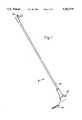
- FIG. 1is a perspective view of a vertically adjustable support
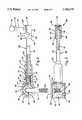
- FIG. 2is an elevational view, partially in cross section, of the vertically adjustable support of FIG. 1 with the lock pin in a locked position;
- FIG. 3is a plan view, partially in cross section, of the vertically adjustable support of FIG. 2;
- FIG. 4is an elevational view, partially in cross section, of the vertically adjustable support of FIG. 2 with the lock pin in a released position;
- FIG. 5is a perspective view of a first embodiment of a limb support system including the vertically adjustable support of FIG. 1;
- FIG. 6is a perspective view of an adjustable support
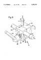
- FIG. 7is a side elevational view of a ratcheting table clamp
- FIG. 8is a front elevational view of the ratcheting table clamp of FIG. 7;
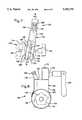
- FIG. 9is a cross-sectional view taken along line 9--9 of FIG. 7;
- FIG. 10is a perspective view of a second embodiment of a limb support system including the ratcheting table clamp of FIG. 7;
- FIG. 11is a side elevational view of a variation of the ratcheting table clamp of FIG. 7;
- FIG. 12is a rear elevational view of the ratcheting table clamp of FIG. 11.
- FIG. 5An adjustable limb support system according to a first embodiment of the invention is shown in FIG. 5.
- the systemcomprises a vertically adjustable support 8, a floating or swinging boot 10, and an adjustable support 12.
- the vertically adjustable support 8is best shown in FIG. 1. At one end of the vertically adjustable support 8 is an attachment 90 which secures the vertically adjustable support 8 to an operating room table 14 (as shown in FIG. 5).
- the attachment 90is fixed to a ratchet mechanism 40.
- the ratchet mechanism 40allows a support arm 20 to rotate upwardly to fixed angular positions.
- a ratchet release 60which allows the support arm 20 to rotate downwardly to fixed angular positions.
- the support arm 20comprises a tube 24 and a housing 22.
- the housing 22has two cylindrically shaped cavities perpendicular to each other. The first cavity is open at each end while the second cavity is open at one end and opens into the first cavity at the other end.
- the second cavityhas a step 23 between two diameters, with the larger diameter towards the open end. The larger diameter of the second cavity is internally threaded 32.
- the two open ends of the housing's 22 first cavityare covered by end caps 26, 27 which are each attached to the housing 22 by two flat head screws 28.
- the tube 24is circular in cross-section and contained at one end within a tube housing 30.
- the tube housing 30is tubularly shaped and has a threaded outer surface 32 which mates with the internal threads of the housing's 22 second cavity.
- the inner diameter of the tube housing 30is sized to receive the outer diameter of the tube 24.
- the outer diameter of the tube 24is sized to mate with the adjustable support 12 (as shown in FIG. 5).
- the tube 24could have a forked-end which sits astride the ratchet wheel 42 and pivots about a pin in the center of the ratchet wheel 42.
- the ratchet mechanism 40consists of a ratchet wheel 42 and a lock pin 46 as seen in FIG. 2.
- the outer diameter of the ratchet wheel 42is sized to fit within the first cavity of the housing 22 so that the housing 22 and the tube 24 can rotate around the ratchet wheel 42 about the centerline of the housing's 22 first cavity and ratchet wheel 42.
- the outer diameter of the ratchet wheel 42has a plurality of serrations 44.
- Each serration 44has a rounded upper edge and a radial lower edge.
- the lock pin 46has a protruding end 47 shaped to engage the ratchet wheel 42 serrations 44 and lock the housing 22 and the tube 24 in position.
- the ratchet wheel 44 of the preferred embodimenthas five serrations 44 which lock the tube 24 in five fixed angular positions. It will be observed that a greater or fewer number of fixed angular positions could be utilized.
- the fixed positions of the preferred embodimentare -26, 0 (horizontal), 26, 52 and 78 degrees. The zero degree, or horizontal, position is shown in FIGS. 2 and 3. In order to lock the tube 24 in a fixed position, the lock pin 46 is urged into the serration 44 by a spring element 50.
- the preferred maximum angular positionis 78 degrees in order to reduce patient risk.
- a 90 degree positionwould result in pressure in the trocar area. If the surgeon requires the patient's limb to be vertical or 90 degrees, it can be accomplished by adjusting the vertically adjustable support to the 78 degree position and gaining an additional 12 degrees by tilting the table 14. This eliminates the pressure on the trocar area and reduces patient risk of excess hip flexion.
- the preferred embodiment of the spring element 50is a helical coil compression spring 52 with a lock body 54 and spring cap 56.
- the spring 52must have a spring force large enough to hold the lock pin 46 in the serration 44 of the ratchet wheel 42 when a limb is being supported.
- the spring forcemust also be small enough so that it can be easily overcome by the ratchet release 60.
- the spring 52is one inch long with a 0.845 inch outer diameter and made of 0.085 inch diameter music wire. It will be noted that other embodiments of the spring element 50 known to those skilled in the art are possible, such as a leaf spring.
- the lock body 54is cylindrically shaped having a step 57 between two diameters, as seen in FIG. 2.
- the larger diameteris sized to slide within the smaller diameter of the housing's 22 second cavity.
- Preferably the large diameteris recessed 55 to ease sliding within the housing 22.
- the smaller diameteris sized to fit within the inner diameter of the spring 52.
- the lock pin 46is fixed to the large diameter end of the lock body 54.
- the spring cap 56is tubularly shaped with an inner diameter sized to slide over the small diameter of the lock body 54, and an outer diameter sized to fit within the inner diameter of the spring 52.
- the spring cap 56also has a flange with a diameter sized to fit within the large diameter of the housing's 22 second cavity.
- the flange of the spring cap 56is held against the step 23 in the housing's 22 second cavity by the tube housing 30.
- the springis retained between the flange of the spring cap 56 and the step 57 on the lock body 54. Because the spring cap 56 is fixed to the housing 22, the spring 52 urges the lock body 54 towards the ratchet wheel 42 so that the lock pin 46 engages a serration 44 on the ratchet wheel 42 to lock the housing 22 and the tube 24 in position.
- the ratchet release 60comprises a traction rod 62, a cam 64, and a cam base 66 as seen in FIGS. 2 and 3.
- the traction rod 62is an elongated rod with a diameter sized to fit within the tube 24.
- a first end of the traction rod 62is fixed to the lock body 54.
- the end of the traction rod 62is threaded 74 and mates to an internally threaded hole formed in the small diameter end of the lock body 54 and is spot welded.
- the cam 64 and the cam base 66are tubularly shaped having an inner diameter sized to slide over the outer diameter of the tube 24.
- the upper surface 67 of the cam base 66is angled in relation to its centerline.
- the lower surface 65 of the cam 64is angled in relation to its centerline so that it will contact and mate with the upper surface 67 of the cam base 66.
- the cam base 66forms three internally threaded holes located 90 degrees from each other and sized to cooperate with set screws 68, 69, 71.
- the set screws 68, 69, 71prevent movement of the cam base 66 relative to the tube 24.
- the cam 64is connected 82 to a second end 76 of the traction rod 62.
- the connection 82is made by an end cap 78.
- the end cap 78has a cylindrical portion with a diameter sized to fit within the inner diameter of the tube 24 and a flange portion with a diameter sized to retain the cam 64 on the tube 24.
- the cylindrical portion of the end cap 78forms an internally threaded hole which mates with threads formed by the second end 76 of the traction rod 62.
- the cam base 66 position along the axis of the tube 24is adjusted to ensure that the cam 64 is constrained between the cam base 66 and the end cap 78.
- TEFLONpolytetrafluoroethylene, commercially sold as TEFLON, washer 80 is located between the cam 64 and end cap 78.
- the TEFLON washer 80reduces the friction between the cam 64 and end cap 78 and thereby eases the rotation of the cam 64.
- connection 82 between the cam 64 and traction rod 62known to those skilled in the art are possible.
- the end cap 78could be rigidly attached to the cam 66 with the traction rod 62 passing through the end cap 78 having a restraint attached to restrain the end cap 78 and cam 64.
- the lock pin 46 disengaged from the ratchet wheel 42is best shown in FIG. 4.
- a handle 70 provided with a grip 72is turned to rotate the cam 64 about the tube 24.
- the cam 64 rotatesthe cam's angled contact surface 65 rides up the angled contact surface 67 of the cam base 66.
- the end cap 78is urged outward thus causing the traction rod 62 to pull the lock body 54 outward by compressing the spring 52 until the lock pin 46 disengages from the serration 44 on the ratchet wheel 42.
- the housing 22 and the tube 24can be rotated downward about the ratchet wheel 42 to a new vertical position.
- the handle 70is then turned in the opposite direction to return the cam 64 and traction rod 62 back to their original position causing the spring 52 to urge the lock pin 46 back into engagement with the ratchet wheel 42 serration 44 at the new vertical position.
- the attachment 90consists of a post 92 having a bend and is secured to the ratchet wheel 42.
- the post 92is preferably bent such that an end portion 93 angularly extends from the rotational plane about the ratchet wheel 42 when the post 92 is firmly attached to the ratchet wheel 42.
- the post 92is bent preferably an angle in the range of 10 degrees to about 30 degrees, and more preferably, an angle of about 20 degrees. It will be noted that the post could be bent to other angles.
- the post 92is bent so that the vertically adjustable support 8 extends outwardly from the side of the table 14 to which it is attached (FIG. 5). This positions the stirrup or boot 10 to automatically abduct or separate the limbs of the patient.
- the post 92is secured by a threaded and pinned end 95 which mates to an internally threaded hole formed in the ratchet wheel 42.
- the post 92could be secured by other methods known to those skilled in the art.
- the post 92could be welded to the ratchet wheel 42.
- the post 92extends from the ratchet wheel 42 through an opening 96 formed by the housing 22.
- the post 92 lengthis sized to locate the adjustable vertical support 8 at a range of desired heights.
- the post end portion 93preferably is knurled to allow the post 92 to be more readily clamped to the operating room table 14 (as seen in FIGS. 2 and 5).
- the attachment 90could consist of a bracket with two flanges that are rigidly fixed to opposing sides of a ratchet wheel that extends out of the two openings of the housing's 22 first cavity.
- the lower side of the bracketcould have a pin that would allow rotation of the system and easily be clamped to the operating room table 14
- a thread locking compoundis applied to the threaded connections between the tube housing 30 and the housing 22, the traction rod 62 and the end cap 78, and the post 92 and the ratchet wheel 42, as seen in FIG. 2.
- Other fastener locking devicesknown to those skilled in the art are possible and could be utilized to prevent the loosening of the threaded connections after repeated usage of the vertically adjustable support 8.
- the boot 10is provided with a transversely extending connecting rod 11.
- the connecting rod 11is welded, or otherwise connected, to a bracket 13 fastened to the boot 10.
- the connecting rod 11is retained within the adjustable support 12, the boot 10 can generally float or freely rotate about the axis of the connecting rod 11.
- the preferred embodiment of the adjustable support 12comprises a retaining block 79, a compression block 84, a compression head 86, a washer 91, and two set screws (not shown).
- Each blockdefines a cylindrical passage 83, 85 for receiving the connecting rod 11 and tube 24 respectively.
- the cylindrical passage 83 in the retaining block 79is sized to contain the connecting rod 11 secured to the limb support or boot 10 (as seen in FIG. 5).
- the cylindrical passage 85 in the compression block 84is sized to receive the tube 24 of the vertical adjustable support 8 (as seen in FIG. 5).
- the compression block 84defines a slot 89 which extends from one edge of the compression block 84 to the cylindrical passage 85.
- the blocks 79, 84further define a hole 77 at right angles to the cylindrical passages 83, 85, and through the slot 89.
- the hole 77is internally threaded at a portion within the retaining block 79.
- the retaining block 79also defines two internally threaded holes or openings (not shown) extending from a back surface to the cylindrical passage 83 to cooperate with the set screws.
- One set screwcontacts the boot connecting rod 11 to control the ease of rotation of the boot 10 about the axis of the connecting rod 11 and the other set screw controls the angle.
- the compression head 86has a threaded member 81 and a handle 87.
- the threaded member 81is inserted through the hole 77 and cooperates with the internal threads defined in the retaining block 79.
- the washer 91is located on the threaded member 81 between the compression head 86 and the compression block 84 to decrease friction and provide smoother tightening of the compression head 86.
- the washeris made of nylon.
- the vertically adjustable support 8is in the zero degree or horizontal position.
- the post 92is removably secured in socket 16 and rotationally held by clamp 18.
- the socket 16is typically a fitting located on the side of an operating room table 14. Due to the bend in the post 92, the vertically adjustable support 8 extends angularly outwardly from the side of the table 14.
- the adjustable support 12is received on the tube 24 of the vertically adjustable support 8.
- the adjustable supportreceives the connecting rod 11 which is secured.
- a second adjustable limb support systemis typically secured to the opposed side of the table 14 in the same manner by a post bent in the opposite direction (not shown). In this configuration a patient lies with their back on the table and a leg portion or foot in each boot.
- the orientation and position of the legcan be adjusted by both the adjustable support 12 and the vertically adjustable support 8.
- the surgeoncan unlock the adjustable support 12 by turning the handle 87.
- the adjustable support 12can then be translated along or rotated about the axis of the tube 24.
- the retaining block 79 and attached boot 10can also be rotated relative to the compression block 84 about an axis perpendicular to both the axis of the connecting rod 11 and the axis of the tube 24.
- the surgeoncan raise the adjustable support 12 to any of the fixed positions or vertical heights by pushing upwardly on the tube 24.
- the vertically adjustable support 8automatically locks into one of the fixed positions or vertical heights.
- the adjustable support system 12is locked by turning the handle 87 back to the tightened position. It should be noted that the boot 10 floats or is free to swing or rotate about the axis of the connecting rod at all times. Therefore, the vertically adjustable support 8 can be raised or lowered in many situations without unlocking the adjustable support 12 because the floating or swinging boot 10 will automatically adjust for the new position.
- the surgeoncan lower the vertically adjustable support 8 to one of the fixed positions or vertical heights by turning the handle 70.
- the handle 70is returned to its original position and the tube 24 is locked in place.
- the above described adjustmentscan be made in any combination and whenever the surgeon desires the limb to be in a new orientation or position. As can be seen by the above described adjustments, they can be readily made by one person during surgery.
- FIG. 10An adjustable limb support system 100 according to a second embodiment of the invention is shown in FIG. 10.
- the system 100includes a vertically adjustable support 102, an adjustable support 12 and a boot 10.
- the adjustable support 12 and the boot 10are the same as described above in the description of the first embodiment.
- the vertically adjustable support 102includes a support arm 104, such as a tube or rod, and a ratcheting table clamp 106.
- the table clamp 106secures the vertically adjustable support 102 to a side rail 108 of operating room table 110.
- the ratcheting table clamp 106is shown in FIGS. 7, 8, and 9. As best seen in FIG. 7, the table clamp 106 includes an attachment 112 which has a clamping portion 114 that is generally C-shaped in cross-section and is sized and shaped to receive the side rail 108 of the table 110 (FIG. 10).
- a threaded rod 116extends through a threaded opening 118 (FIG. 9) in the closed side of the clamping portion 114.
- the rod 116has a first end within the clamping portion 114 that has an increased diameter. The increased diameter provides a clamping surface 120 for contacting the side rail 108 of the table 110 and also prevents the first end of the rod 116 from passing through the threaded opening 118 in the clamping portion 114.
- a second end of the threaded rodis provided with a handle 122 such that the rod 116 can be rotated to move the clamping surface 120 toward and away from the open end of the clamping portion 114.
- FIGS. 11 and 12An alternative and preferred clamping portion 214 is shown in FIGS. 11 and 12.
- the clamping portion 214is generally C-shaped in cross-section and is sized and shaped to receive the side rail 108 of the table 110 (FIG. 10).
- Opposed walls 216downwardly extend from the bottom of the clamping portion 214 to form an open space 218.
- a shaft 220extends through openings in the opposed walls 216.
- An eccentric cam 222is attached to the shaft 220 within the open space 218 by fastener 224.
- Attached to an outer end of the shaft 220is a handle 226.
- a pin 228has a first end 230 extends through an opening 232 in the clamping portion 214.
- a second end 234 of the pin 228has an enlarged diameter which contacts the cam 222.
- a helical coil spring 236is located on the pin 228 within the open space 218 to bias the second end of the pin 228 towards the cam 222.
- the pin 228When the large diameter of the cam 222 is vertical (FIG. 12), the pin 228 is in its uppermost position within the clamping portion 214.
- the pin 228is sized to clamp the side rail 108 of the table 110 (FIG. 10) when in this position.
- the cam 222is sized and shaped to retain the shaft 220 between the walls 216 and provide an adequate distance of axial travel for the pin 228.
- the handle 226is rotated to rotate the shaft 220 and cam 222 until the small diameter of the cam 222 is in the vertical position (FIG.
- the spring 236biases the pin 228 against the cam 222 so that the first end 230 of the pin 228 moves downward until it is no longer within the clamping portion 214.
- a pair of pins 238are provided at the top of the clamping portion 214 to provide an upper clamping surface for the side rail 108 of the table 110 (FIG. 10).
- the attachment 112also includes a mounting portion 124 and a spacer portion 126 connecting the mounting portion 124 to the clamping portion 114.
- the mounting portion 124is cylindrically-shaped and has an opening 128 in which the rod 116 passes through to the threaded opening 118 of the clamping portion 114.
- the spacer portion 126is generally wedge-shaped and circular in cross-section.
- the diameter of the mounting portion 124is smaller than the diameter of the spacer portion 126 forming an annularly-shaped seat 130.
- the spacer portion 126is angled such that the mounting portion 124 is angled downwardly.
- the spacer portion 126is preferably sized such that the axis of the mounting portion 124 is angled downwardly.
- the axisis preferably angled in the range from about 10 degrees to about thirty degrees and more preferably the axis is angled about 20 degrees. It will be noted that the spacer portion 126 could be sized for other angles. This angle causes the rotational plane of the vertical adjustable support 102 to extend outwardly at an angle from the side of the table 110 to automatically abduct the limbs of the patient as described above in the description of the first embodiment.
- a ratchet mechanism 132is fixed to the attachment 112 and allows the support arm 104 to rotate to fixed angular positions.
- the ratchet mechanism 132includes a ratchet wheel 134 and a lock pin 136.
- An inner diameter of the ratchet wheel 134is sized to receive the mounting portion 124 of the attachment 112 such that the ratchet wheel 134 is adjacent or near the seat 130.
- a mounting screw 138extends from the ratchet wheel 134 to the mounting portion 124 of the attachment 112 to prevent rotation of the ratchet wheel 134.
- the outer diameter of the ratchet wheel 134has a plurality of serrations 140. Each serration 140 has an angled upper edge and an angled lower edge.
- the ratchet wheel 134 of the illustrated embodimenthas sixteen serrations 134 to lock the support arm 104 in sixteen fixed angular positions.
- the serrationsare located so that the support arm is rotatable over an arc of about 180 degrees that is from about horizontal to about horizontal. It will be noted that a greater or fewer number of fixed angular positions could be provided or a greater, smaller, or different arc could be provided. Additionally, a limit to the angular positions that reduces patient risk due to excess hip flexion could also be provided as described above in the description of the first embodiment.
- the lock pin 136is generally cylindrically-shaped and has a protruding end 142 shaped to engage the ratchet wheel serrations 140.
- the lock pin 136is urged into the serration 140 by a spring element 144.
- the spring element 144is preferably a helical coil compression spring having an inner diameter sized to surround the lock pin 136 and is held on the lock pin 136 by a retaining ring 146.
- the table clamp 106also includes a housing 148 which supports the support arm 104.
- the housing 148has a generally cylindrically-shaped first portion 150 and generally rectangularly-shaped second portion 152 radially extending from the first portion 150.
- the first portion 150has a cylindrically-shaped cavity 154 open at both ends with a diameter sized to receive the ratchet wheel 134.
- the housing 148is retained about the ratchet wheel 134 by a cover plate 156 and a retaining ring 158.
- the cover plate 156has an outer diameter generally equal to the diameter of the first portion 150 of the housing 148.
- the cover plate 156is fixed to the mounting portion 124 of the attachment 112 by four mounting screws 160 extending into threaded openings 162 in the mounting portion 124 of the attachment 112. Spacers 164 are provided to space the cover plate 156 an adequate distance from the mounting portion 124 of the attachment 112.
- the retaining ring 158is annularly-shaped having an outer diameter generally equal to the first portion 150 of the housing 148 and an inner diameter sized to receive the mounting portion 124 of the attachment 112.
- the retaining ring 158is located between the seat 130 of the attachment 112 and the housing 148. Assembled in this manner the housing 148 is free to rotate about the ratchet wheel 134 on the axis of the mounting portion 124.
- Rotation of the housing 148is limited by a stop such as slot 166 in the first portion 150 of the housing 148 and a screw 168 fixed to the ratchet wheel 134 as best seen in FIG. 9.
- the housing 148is rotatable until the screw 168 contacts an end of the slot 166.
- the slot 166is sized and located so that the housing 148 is rotatable only over an arc where the lock pin 136 engages the serrations 140 of the ratchet wheel 134.
- the second portion 152 of the housing 148has first and second bores 170, 172 perpendicular to the cavity 154 of the first portion 150.
- the first bore 170is open at both ends and opens into the cavity 154.
- the first bore 170has a step 174 between two diameters.
- a first diameteris adjacent the cavity 154 and is sized for receiving the spring element 144 and a second diameter is sized for receiving the lock pin 136.
- the second bore 172is a blind bore and is sized to receive an end of the support arm 104.
- a support 176 having a threaded opening 178is fixed, such as by welding, to the housing 148 adjacent an opening 180 which opens into the second bore 172.
- a threaded rod 182extends cooperates with the threaded opening 178 of the support to clamp the support arm 104 within the second bore 172.
- a handle 184is provided at an outer end of the rod 182 such that the rod 182 can be turned to move the rod 182 into and out of the second bore 172.
- a ratchet release 186is provided which disengages the lock pin 136 from the serration 140 and allows the support arm 104 to rotate back to the fixed angular positions.
- the ratchet release 186includes a knob 188 located at an outer end of the lock pin 136. When the knob 188 is pulled outwardly with a force adequate to overcome the spring element 144, the spring element 144 is compressed against the step 174 and the protruding end 142 of the lock pin 136 disengages from the serration 140 of the ratchet wheel 134. Outward movement of the lock pin 136 is limited by a pin 190 fixed to the housing 148 which engages an end of an axially extending groove 192 on the lock pin 136.
- the inventionis shown in a leg support application.
- the ratcheting table clamp 106is removably secured to the side rail 108 of the operating room table 110 and the support arm 104 is received by table clamp 106. Due to the angle of the table clamp 106, the support arm 104 extends angularly outwardly in a lateral direction from the side of the table 110.
- the adjustable support 12is received on the support arm 104 of the vertically adjustable support 102.
- the adjustable support 12receives the connecting rod 11 of the boot 10.
- a second system according to the inventionis typically secured to the opposed side of the table (not shown).
- the second systemis a mirror image of the first such that the support arm extends outwardly in a lateral direction from the opposed side of the table. In this configuration a patient lies with their back on the table and a leg portion or foot in each boot 10.
- the orientation and position of the legcan be adjusted by both the adjustable support 12 and the vertically adjustable support 102 as described above for the first embodiment.
- the knob 188(FIG. 10) is pulled instead of turning the handle 70 (FIG. 5).
Landscapes
- Health & Medical Sciences (AREA)
- Engineering & Computer Science (AREA)
- Biomedical Technology (AREA)
- Life Sciences & Earth Sciences (AREA)
- Animal Behavior & Ethology (AREA)
- General Health & Medical Sciences (AREA)
- Public Health (AREA)
- Veterinary Medicine (AREA)
- Nursing (AREA)
- Orthopedic Medicine & Surgery (AREA)
- Heart & Thoracic Surgery (AREA)
- Vascular Medicine (AREA)
- Accommodation For Nursing Or Treatment Tables (AREA)
Abstract
Description
Claims (20)
Priority Applications (1)
| Application Number | Priority Date | Filing Date | Title |
|---|---|---|---|
| US08/412,148US5582379A (en) | 1994-06-24 | 1995-03-28 | Adjustable limb support system |
Applications Claiming Priority (2)
| Application Number | Priority Date | Filing Date | Title |
|---|---|---|---|
| US08/265,647US5560577A (en) | 1994-06-24 | 1994-06-24 | Adjustable limb support system |
| US08/412,148US5582379A (en) | 1994-06-24 | 1995-03-28 | Adjustable limb support system |
Related Parent Applications (1)
| Application Number | Title | Priority Date | Filing Date |
|---|---|---|---|
| US08/265,647Continuation-In-PartUS5560577A (en) | 1994-06-24 | 1994-06-24 | Adjustable limb support system |
Publications (1)
| Publication Number | Publication Date |
|---|---|
| US5582379Atrue US5582379A (en) | 1996-12-10 |
Family
ID=46249613
Family Applications (1)
| Application Number | Title | Priority Date | Filing Date |
|---|---|---|---|
| US08/412,148Expired - LifetimeUS5582379A (en) | 1994-06-24 | 1995-03-28 | Adjustable limb support system |
Country Status (1)
| Country | Link |
|---|---|
| US (1) | US5582379A (en) |
Cited By (85)
| Publication number | Priority date | Publication date | Assignee | Title |
|---|---|---|---|---|
| US5642819A (en)* | 1996-03-13 | 1997-07-01 | Ronia; Ernesto | Christmas stocking holder |
| US5802641A (en)* | 1997-03-07 | 1998-09-08 | Amatech Corporation | Leg holder system for simultaneous positioning in the abduction and lithotomy dimensions |
| US5918330A (en)* | 1996-08-14 | 1999-07-06 | Allen Medical Systems, Inc. | Ratchet mechanism for booted surgical stirrup |
| GB2336314A (en)* | 1998-04-16 | 1999-10-20 | Giovanni Ambroselli | Angularly adjustable leg support apparatus for fitting to an operating table |
| US5996954A (en)* | 1997-10-14 | 1999-12-07 | Rosen Products Llc | Stowable support apparatus |
| US6058534A (en)* | 1997-04-04 | 2000-05-09 | Amatech Corporation | Locking-cylinder supported surgical boot |
| US6202230B1 (en) | 1997-11-07 | 2001-03-20 | Hill-Rom, Inc. | Surgical table apparatus |
| WO2001030279A1 (en)* | 1999-10-29 | 2001-05-03 | Novortho Sa | Adjustable mechanical device linking two elements together |
| US6289537B1 (en)* | 2000-02-09 | 2001-09-18 | Stryker Corporation | Patient support |
| US6449851B1 (en)* | 1997-01-31 | 2002-09-17 | Black & Decker Inc. | Powered reciprocating saw and clamping mechanism |
| US6629944B2 (en)* | 2001-03-06 | 2003-10-07 | Kenneth Thomas Smart | Limb-positioning and traction device |
| RU2218065C1 (en)* | 2002-04-04 | 2003-12-10 | Слабов Андрей Герасимович | Display panel |
| US6663055B2 (en)* | 2000-03-15 | 2003-12-16 | The Or Group, Inc. | Armboard assembly |
| US6704959B2 (en)* | 2001-08-13 | 2004-03-16 | Peter Schuerch | Adjustable position limb support for surgical tables |
| US6739006B2 (en) | 1997-11-07 | 2004-05-25 | Hill-Rom Services, Inc. | Head section support for a surgical table apparatus |
| US6754923B2 (en) | 1997-11-07 | 2004-06-29 | Hill-Rom Services, Inc. | Leg section support for a surgical table |
| US20040133979A1 (en)* | 2003-01-13 | 2004-07-15 | Newkirk David C. | Orthopedic table apparatus |
| GB2402071A (en)* | 2003-05-01 | 2004-12-01 | Univ Wolverhampton | Limb Support |
| US20050160533A1 (en)* | 2004-01-23 | 2005-07-28 | Hillenbrand Industries | Surgical positioning apparatus |
| US20060180721A1 (en)* | 2002-12-13 | 2006-08-17 | Juergen Buehler | Swivel arm assembly for plumbing fixtures |
| US20060190089A1 (en)* | 2005-02-18 | 2006-08-24 | Howmedica Osteonics Corp. | Internal adaptor for hip acetabular cage |
| US20060278785A1 (en)* | 2005-05-26 | 2006-12-14 | Sherwood Services Ag | Flexible clamping apparatus for medical devices |
| US20070035217A1 (en)* | 2003-02-13 | 2007-02-15 | Bochner Ronnie Z | Device for facilitating medical examination |
| US20070106392A1 (en)* | 2005-11-08 | 2007-05-10 | Howmedica Osteonics Corp. | Acetabular cup locking mechanism |
| WO2007140729A1 (en)* | 2006-06-08 | 2007-12-13 | Borcad Cz S.R.O. | Biaxial joint |
| US20070289599A1 (en)* | 2002-06-26 | 2007-12-20 | Pilgrim Innovations, Llc | Anterior support device |
| US20080054698A1 (en)* | 2002-06-26 | 2008-03-06 | Pilgrim Innovations, Llc | Combination twin adapter mounting plate and a pair of anterior supports |
| US20080203644A1 (en)* | 2007-02-28 | 2008-08-28 | Dasilva Manuel F | Operating table support clamp |
| US20080221590A1 (en)* | 2007-03-05 | 2008-09-11 | Intuitive Surgical, Inc. | Apparatus for positioning and holding in place a manually manipulated medical device during the performance of a robotically assisted medical procedure |
| US20080272254A1 (en)* | 2007-05-04 | 2008-11-06 | Tyco Healthcare Group Lp | Medical Device Safety Support with Infinite Positioning |
| US20090001238A1 (en)* | 2007-06-29 | 2009-01-01 | Draeger Medical Systems, Inc. | Tilt and swivel mounting for monitors and other devices |
| US7481751B1 (en)* | 2007-05-08 | 2009-01-27 | Floyd Arnold | Ankle/leg therapy device |
| US20090125055A1 (en)* | 2007-11-08 | 2009-05-14 | Tyco Healthcare Group Lp | Telescopingly adjustable clamp |
| US7536734B2 (en) | 2005-01-31 | 2009-05-26 | Hill-Rom Services, Inc. | Birthing support apparatus |
| US7546993B1 (en) | 2008-03-25 | 2009-06-16 | Tyco Healthcare Group Lp | Flexible clamping apparatus for medical devices |
| US20090249551A1 (en)* | 2008-04-03 | 2009-10-08 | Pilgrim Innovations, Llc | Combination treatment device and an anterior support device |
| US20100189578A1 (en)* | 2009-01-26 | 2010-07-29 | Tyco Healthcare Group Lp | Mount for a compression control unit |
| US20100293719A1 (en)* | 2008-04-03 | 2010-11-25 | Klemm Kurt W | Combination treatment device and an anterior support device |
| US20110190676A1 (en)* | 2005-11-30 | 2011-08-04 | Smith & Nephew, Inc. | Hip distraction |
| US20110185506A1 (en)* | 2008-04-08 | 2011-08-04 | Paulus Maria Antonius Broens | Leg support instrument and supporting method |
| USD659839S1 (en) | 2010-08-16 | 2012-05-15 | Tyco Healthcare Group Lp | Support for a pneumatic compression controller |
| CN102512305A (en)* | 2011-12-07 | 2012-06-27 | 易金阳 | Foot pedal structure for medical operating table |
| US8308114B2 (en)* | 2009-02-25 | 2012-11-13 | Tensolite LLC | Electronic flight bag mounting bracket |
| US8322342B2 (en) | 2008-07-25 | 2012-12-04 | Allen Medical Systems, Inc. | Operative arm support |
| WO2013016183A1 (en)* | 2011-07-22 | 2013-01-31 | Stryker Corporation | Multi-position limb holder |
| USD675741S1 (en) | 2010-08-16 | 2013-02-05 | Covidien Lp | Pneumatic compression controller |
| US20130193176A1 (en)* | 2012-02-01 | 2013-08-01 | Denis Khoo | Securing Apparatus for a Roof Rack |
| US20130247919A1 (en)* | 2010-12-07 | 2013-09-26 | Socpra Sciences Et Genie S.E.C. | Positioning apparatus for biomedical use |
| EP2671558A3 (en)* | 2012-06-06 | 2014-01-22 | Allen Medical Systems, Inc. | Surgical accessory interface device |
| US8640286B1 (en) | 2012-12-20 | 2014-02-04 | Leon Hochman | Medical bed |
| US8840077B2 (en) | 2011-08-24 | 2014-09-23 | Coopersurgical, Inc. | Table-mounted surgical instrument stabilizers |
| US8875329B2 (en)* | 2013-03-11 | 2014-11-04 | David Julian Gomez | Arm tucking device for use with an operating room table |
| US20150059097A1 (en)* | 2013-08-28 | 2015-03-05 | Contour Fabricators, Inc. | Surgical table arm support assembly and surgical table |
| US9107792B2 (en) | 2012-09-07 | 2015-08-18 | Allen Medical Systems, Inc. | Carriage for a surgical boot of a hip distractor |
| USRE46032E1 (en) | 2005-11-30 | 2016-06-21 | Smith & Nephew, Inc. | Hip distraction |
| WO2016100966A1 (en)* | 2014-12-19 | 2016-06-23 | New York Society For The Ruptured And Crippled Maintaining The Hospital For Special Surgery | System and apparatus for securing knee joint with a load for magnetic resonance imaging |
| US9381130B2 (en) | 2011-06-02 | 2016-07-05 | Allen Medical Systems, Inc. | Surgical foot support with tightener system |
| USRE46064E1 (en) | 2005-11-30 | 2016-07-12 | Smith & Nephew, Inc. | Hip distraction |
| US9655764B2 (en) | 2011-06-02 | 2017-05-23 | Allen Medical Systems, Inc. | Surgical foot support with handles |
| US9730851B2 (en) | 2012-09-07 | 2017-08-15 | Allen Medical Systems, Inc. | Surgical support system |
| JP2018057904A (en)* | 2014-11-05 | 2018-04-12 | アレン メディカル システムズ インコーポレイテッドAllen Medical Systems, Inc. | Boot stirrup |
| US9951904B2 (en) | 2015-03-24 | 2018-04-24 | Stryker Corporation | Rotatable seat clamps for rail clamp |
| US10105274B2 (en)* | 2015-02-10 | 2018-10-23 | Ronald M. Carn | Adjustable surgical support system |
| US10478364B2 (en) | 2014-03-10 | 2019-11-19 | Stryker Corporation | Limb positioning system |
| EP3607925A1 (en)* | 2016-04-01 | 2020-02-12 | Allen Medical Systems, Inc. | Boot carriage for repositioning a surgical boot along a support rod |
| USD878836S1 (en) | 2017-08-17 | 2020-03-24 | Stryker Corp. | Table extender |
| CN111297609A (en)* | 2020-03-09 | 2020-06-19 | 皖南医学院第一附属医院(皖南医学院弋矶山医院) | Fester organism nursing appearance |
| US10828218B2 (en) | 2015-06-05 | 2020-11-10 | Stryker Corporation | Surgical table and accessories to facilitate hip arthroscopy |
| US10842700B2 (en) | 2012-10-17 | 2020-11-24 | Peter E. Schuerch, JR. | Adjustable position limb support for surgical tables, including quick-connect universal boot mount |
| US11033355B2 (en)* | 2018-12-31 | 2021-06-15 | Biosense Webster (Israel) Ltd. | Mounting device for medical equipment |
| CN113081637A (en)* | 2021-04-01 | 2021-07-09 | 杭州键嘉机器人有限公司 | Leg fixing device |
| US11129683B2 (en) | 2016-07-14 | 2021-09-28 | Intuitive Surgical Operations, Inc. | Systems and methods for controlling a surgical instrument |
| US11234885B2 (en) | 2018-02-20 | 2022-02-01 | Allen Medical Systems, Inc. | Adjustable lithotomy positioning apparatus with a limb rest |
| US20220062097A1 (en)* | 2020-09-01 | 2022-03-03 | Metro Men's Health | Penile holder |
| US11389200B1 (en)* | 2021-01-29 | 2022-07-19 | Globus Medical, Inc. | Systems and methods for leg stabilization during knee arthroplasty surgery |
| US11510805B2 (en) | 2017-02-06 | 2022-11-29 | Stryker Corp. | Anatomical gripping system for gripping the leg and foot of a patient when effecting hip distraction and/or when effecting leg positioning |
| US20220394932A1 (en)* | 2021-01-27 | 2022-12-15 | Kurt Macey | Low stress plant limb trainer apparatus |
| US11559455B2 (en) | 2017-02-06 | 2023-01-24 | Stryker Corp. | Distraction frame for effecting hip distraction |
| US11564855B2 (en) | 2020-09-28 | 2023-01-31 | Stryker Corporation | Systems and methods for supporting and stabilizing a patient during hip distraction |
| US11684532B2 (en) | 2017-02-06 | 2023-06-27 | Stryker Corp. | Method and apparatus for supporting and stabilizing a patient during hip distraction |
| US11877962B2 (en) | 2012-10-17 | 2024-01-23 | Peter E. Schuerch, JR. | Adjustable position limb support for surgical tables, including locking gas cylinder |
| EP4331549A1 (en)* | 2022-09-01 | 2024-03-06 | Globus Medical, Inc. | Systems and methods for patient positioning background |
| US11992442B2 (en)* | 2016-09-28 | 2024-05-28 | Mizuho Corporation | Surgical head fixation apparatus |
| US12245976B2 (en) | 2012-10-17 | 2025-03-11 | Peter E. Schuerch, JR. | Adjustable position limb support for surgical tables, including distraction system |
| US12295894B2 (en) | 2021-11-09 | 2025-05-13 | Allen Medical Systems, Inc. | Surgical traction boot having resilient heel pad and medial and lateral straps |
Citations (13)
| Publication number | Priority date | Publication date | Assignee | Title |
|---|---|---|---|---|
| US612373A (en)* | 1898-10-11 | allison | ||
| US891678A (en)* | 1906-06-21 | 1908-06-23 | James H Downey | Operating and fracture table. |
| US891679A (en)* | 1907-03-11 | 1908-06-23 | James H Downey | Operating-table. |
| US1823248A (en)* | 1927-04-20 | 1931-09-15 | W D Allison Company | Examining table leg rest |
| US2465781A (en)* | 1946-04-12 | 1949-03-29 | Wallace B Creamer | Embalmer's aid |
| US2679445A (en)* | 1951-11-23 | 1954-05-25 | W D Allison Company | Physician's examining table |
| US4526355A (en)* | 1982-09-29 | 1985-07-02 | Moore Robert R | Arthroscopic leg holder |
| US4564164A (en)* | 1984-06-08 | 1986-01-14 | Allen R Daniel | Adjustable support system |
| US4615516A (en)* | 1985-09-16 | 1986-10-07 | Sodem Diffusion S.A. | Splint for surgical operations on the knee |
| US4913413A (en)* | 1989-06-09 | 1990-04-03 | Faro Medical Technologies Inc. | Universal leg holder |
| US5116008A (en)* | 1991-04-03 | 1992-05-26 | Edgewater Medical Equipment Systems, Inc. | Adjustable support assembly |
| US5135210A (en)* | 1989-05-01 | 1992-08-04 | Michelson Gary K | Surgical armboard attachment device |
| US5157800A (en)* | 1991-04-15 | 1992-10-27 | Hill-Rom Company, Inc. | Foot section for birthing bed |
- 1995
- 1995-03-28USUS08/412,148patent/US5582379A/ennot_activeExpired - Lifetime
Patent Citations (14)
| Publication number | Priority date | Publication date | Assignee | Title |
|---|---|---|---|---|
| US612373A (en)* | 1898-10-11 | allison | ||
| US891678A (en)* | 1906-06-21 | 1908-06-23 | James H Downey | Operating and fracture table. |
| US891679A (en)* | 1907-03-11 | 1908-06-23 | James H Downey | Operating-table. |
| US1823248A (en)* | 1927-04-20 | 1931-09-15 | W D Allison Company | Examining table leg rest |
| US2465781A (en)* | 1946-04-12 | 1949-03-29 | Wallace B Creamer | Embalmer's aid |
| US2679445A (en)* | 1951-11-23 | 1954-05-25 | W D Allison Company | Physician's examining table |
| US4526355A (en)* | 1982-09-29 | 1985-07-02 | Moore Robert R | Arthroscopic leg holder |
| US4564164A (en)* | 1984-06-08 | 1986-01-14 | Allen R Daniel | Adjustable support system |
| US4564164B1 (en)* | 1984-06-08 | 1994-08-09 | Leasing Inc As | Adjustable support system |
| US4615516A (en)* | 1985-09-16 | 1986-10-07 | Sodem Diffusion S.A. | Splint for surgical operations on the knee |
| US5135210A (en)* | 1989-05-01 | 1992-08-04 | Michelson Gary K | Surgical armboard attachment device |
| US4913413A (en)* | 1989-06-09 | 1990-04-03 | Faro Medical Technologies Inc. | Universal leg holder |
| US5116008A (en)* | 1991-04-03 | 1992-05-26 | Edgewater Medical Equipment Systems, Inc. | Adjustable support assembly |
| US5157800A (en)* | 1991-04-15 | 1992-10-27 | Hill-Rom Company, Inc. | Foot section for birthing bed |
Cited By (135)
| Publication number | Priority date | Publication date | Assignee | Title |
|---|---|---|---|---|
| US5642819A (en)* | 1996-03-13 | 1997-07-01 | Ronia; Ernesto | Christmas stocking holder |
| US5918330A (en)* | 1996-08-14 | 1999-07-06 | Allen Medical Systems, Inc. | Ratchet mechanism for booted surgical stirrup |
| US6449851B1 (en)* | 1997-01-31 | 2002-09-17 | Black & Decker Inc. | Powered reciprocating saw and clamping mechanism |
| US5802641A (en)* | 1997-03-07 | 1998-09-08 | Amatech Corporation | Leg holder system for simultaneous positioning in the abduction and lithotomy dimensions |
| USRE41412E1 (en)* | 1997-03-07 | 2010-07-06 | Allen Medical Systems, Inc. | Leg holder system for simultaneous positioning in the abduction and lithotomy dimensions |
| US6263531B1 (en) | 1997-04-04 | 2001-07-24 | The Or Group, Inc. | Locking-cylinder supported surgical boot |
| US6058534A (en)* | 1997-04-04 | 2000-05-09 | Amatech Corporation | Locking-cylinder supported surgical boot |
| US5996954A (en)* | 1997-10-14 | 1999-12-07 | Rosen Products Llc | Stowable support apparatus |
| US6179263B1 (en) | 1997-10-14 | 2001-01-30 | Rosen Products Llc | Stowable support apparatus |
| US6202230B1 (en) | 1997-11-07 | 2001-03-20 | Hill-Rom, Inc. | Surgical table apparatus |
| US6739006B2 (en) | 1997-11-07 | 2004-05-25 | Hill-Rom Services, Inc. | Head section support for a surgical table apparatus |
| US6276012B2 (en) | 1997-11-07 | 2001-08-21 | Hill-Rom Services, Inc. | Surgical table apparatus |
| US6446287B2 (en) | 1997-11-07 | 2002-09-10 | Hill-Rom Services, Inc. | Surgical table apparatus |
| US6754923B2 (en) | 1997-11-07 | 2004-06-29 | Hill-Rom Services, Inc. | Leg section support for a surgical table |
| GB2336314A (en)* | 1998-04-16 | 1999-10-20 | Giovanni Ambroselli | Angularly adjustable leg support apparatus for fitting to an operating table |
| WO2001030279A1 (en)* | 1999-10-29 | 2001-05-03 | Novortho Sa | Adjustable mechanical device linking two elements together |
| FR2800270A1 (en)* | 1999-10-29 | 2001-05-04 | Novortho | MECHANICAL LINKING DEVICE ADJUSTABLE FROM TWO ELEMENTS TO EACH OTHER |
| US6289537B1 (en)* | 2000-02-09 | 2001-09-18 | Stryker Corporation | Patient support |
| US6663055B2 (en)* | 2000-03-15 | 2003-12-16 | The Or Group, Inc. | Armboard assembly |
| US6629944B2 (en)* | 2001-03-06 | 2003-10-07 | Kenneth Thomas Smart | Limb-positioning and traction device |
| US20040167455A1 (en)* | 2001-03-06 | 2004-08-26 | Smart Kenneth Thomas | Patient-receiving surgical device |
| US6704959B2 (en)* | 2001-08-13 | 2004-03-16 | Peter Schuerch | Adjustable position limb support for surgical tables |
| RU2218065C1 (en)* | 2002-04-04 | 2003-12-10 | Слабов Андрей Герасимович | Display panel |
| US20070289599A1 (en)* | 2002-06-26 | 2007-12-20 | Pilgrim Innovations, Llc | Anterior support device |
| US20080054698A1 (en)* | 2002-06-26 | 2008-03-06 | Pilgrim Innovations, Llc | Combination twin adapter mounting plate and a pair of anterior supports |
| US20060180721A1 (en)* | 2002-12-13 | 2006-08-17 | Juergen Buehler | Swivel arm assembly for plumbing fixtures |
| US7419127B2 (en)* | 2002-12-13 | 2008-09-02 | Hansgrohe Ag | Swivel arm assembly for plumbing fixtures |
| US20040133979A1 (en)* | 2003-01-13 | 2004-07-15 | Newkirk David C. | Orthopedic table apparatus |
| US20070035217A1 (en)* | 2003-02-13 | 2007-02-15 | Bochner Ronnie Z | Device for facilitating medical examination |
| GB2402071A (en)* | 2003-05-01 | 2004-12-01 | Univ Wolverhampton | Limb Support |
| GB2402071B (en)* | 2003-05-01 | 2007-05-30 | Univ Wolverhampton | Limb support |
| US7337483B2 (en) | 2004-01-23 | 2008-03-04 | Allen Medical Systems, Inc. | Surgical positioning apparatus |
| US20050160533A1 (en)* | 2004-01-23 | 2005-07-28 | Hillenbrand Industries | Surgical positioning apparatus |
| US7536734B2 (en) | 2005-01-31 | 2009-05-26 | Hill-Rom Services, Inc. | Birthing support apparatus |
| US20060190089A1 (en)* | 2005-02-18 | 2006-08-24 | Howmedica Osteonics Corp. | Internal adaptor for hip acetabular cage |
| US20060278785A1 (en)* | 2005-05-26 | 2006-12-14 | Sherwood Services Ag | Flexible clamping apparatus for medical devices |
| US7731138B2 (en) | 2005-05-26 | 2010-06-08 | Covidien Ag | Flexible clamping apparatus for medical devices |
| US20070106392A1 (en)* | 2005-11-08 | 2007-05-10 | Howmedica Osteonics Corp. | Acetabular cup locking mechanism |
| US20110190676A1 (en)* | 2005-11-30 | 2011-08-04 | Smith & Nephew, Inc. | Hip distraction |
| USRE46032E1 (en) | 2005-11-30 | 2016-06-21 | Smith & Nephew, Inc. | Hip distraction |
| US10376287B2 (en) | 2005-11-30 | 2019-08-13 | Smith & Nephew, Inc. | Hip distraction |
| US9480614B2 (en)* | 2005-11-30 | 2016-11-01 | Smith & Nephew, Inc. | Hip distraction |
| USRE46064E1 (en) | 2005-11-30 | 2016-07-12 | Smith & Nephew, Inc. | Hip distraction |
| RU2428160C2 (en)* | 2006-06-08 | 2011-09-10 | Боркад Цз С.Р.О. | Biaxial hinge |
| WO2007140729A1 (en)* | 2006-06-08 | 2007-12-13 | Borcad Cz S.R.O. | Biaxial joint |
| CN101340879B (en)* | 2006-06-08 | 2010-07-28 | 博尔察德捷克公司 | Biaxial joint |
| US7686267B2 (en) | 2007-02-28 | 2010-03-30 | Dasilva Manuel F | Operating table support clamp |
| US20080203644A1 (en)* | 2007-02-28 | 2008-08-28 | Dasilva Manuel F | Operating table support clamp |
| US20080221590A1 (en)* | 2007-03-05 | 2008-09-11 | Intuitive Surgical, Inc. | Apparatus for positioning and holding in place a manually manipulated medical device during the performance of a robotically assisted medical procedure |
| US20080272254A1 (en)* | 2007-05-04 | 2008-11-06 | Tyco Healthcare Group Lp | Medical Device Safety Support with Infinite Positioning |
| US7980521B2 (en) | 2007-05-04 | 2011-07-19 | Tyco Healthcare Group Lp | Medical device safety support with infinite positioning |
| US7481751B1 (en)* | 2007-05-08 | 2009-01-27 | Floyd Arnold | Ankle/leg therapy device |
| US8632042B2 (en) | 2007-06-29 | 2014-01-21 | Draeger Medical Systems, Inc. | Tilt and swivel mounting for monitors and other devices |
| US20090001238A1 (en)* | 2007-06-29 | 2009-01-01 | Draeger Medical Systems, Inc. | Tilt and swivel mounting for monitors and other devices |
| US20090125055A1 (en)* | 2007-11-08 | 2009-05-14 | Tyco Healthcare Group Lp | Telescopingly adjustable clamp |
| US8246028B2 (en) | 2007-11-08 | 2012-08-21 | Tyco Healthcare Group Lp | Telescopingly adjustable clamp |
| US7546993B1 (en) | 2008-03-25 | 2009-06-16 | Tyco Healthcare Group Lp | Flexible clamping apparatus for medical devices |
| US20100293719A1 (en)* | 2008-04-03 | 2010-11-25 | Klemm Kurt W | Combination treatment device and an anterior support device |
| US8256047B2 (en) | 2008-04-03 | 2012-09-04 | Klemm Kurt W | Combination treatment device and an anterior support device |
| US20090249551A1 (en)* | 2008-04-03 | 2009-10-08 | Pilgrim Innovations, Llc | Combination treatment device and an anterior support device |
| US8448274B2 (en)* | 2008-04-08 | 2013-05-28 | Academisch Ziekenhuis Groningen | Leg support instrument and supporting method |
| US20110185506A1 (en)* | 2008-04-08 | 2011-08-04 | Paulus Maria Antonius Broens | Leg support instrument and supporting method |
| US8322342B2 (en) | 2008-07-25 | 2012-12-04 | Allen Medical Systems, Inc. | Operative arm support |
| US8133039B2 (en) | 2009-01-26 | 2012-03-13 | Tyco Healthcare Group Lp | Mount for a compression control unit |
| US8414272B2 (en) | 2009-01-26 | 2013-04-09 | Covidien Lp | Mount for a compression control unit |
| US20100189578A1 (en)* | 2009-01-26 | 2010-07-29 | Tyco Healthcare Group Lp | Mount for a compression control unit |
| US8308114B2 (en)* | 2009-02-25 | 2012-11-13 | Tensolite LLC | Electronic flight bag mounting bracket |
| USD659839S1 (en) | 2010-08-16 | 2012-05-15 | Tyco Healthcare Group Lp | Support for a pneumatic compression controller |
| USD675741S1 (en) | 2010-08-16 | 2013-02-05 | Covidien Lp | Pneumatic compression controller |
| US20130247919A1 (en)* | 2010-12-07 | 2013-09-26 | Socpra Sciences Et Genie S.E.C. | Positioning apparatus for biomedical use |
| US9532842B2 (en)* | 2010-12-07 | 2017-01-03 | Conmed Corporation | Positioning apparatus for biomedical use |
| US9381130B2 (en) | 2011-06-02 | 2016-07-05 | Allen Medical Systems, Inc. | Surgical foot support with tightener system |
| US9655764B2 (en) | 2011-06-02 | 2017-05-23 | Allen Medical Systems, Inc. | Surgical foot support with handles |
| US9615987B2 (en) | 2011-07-22 | 2017-04-11 | Stryker Corporation | Multi-position limb holder |
| AU2012287169B2 (en)* | 2011-07-22 | 2015-09-10 | Stryker Corporation | Multi-position limb holder |
| WO2013016183A1 (en)* | 2011-07-22 | 2013-01-31 | Stryker Corporation | Multi-position limb holder |
| US8840077B2 (en) | 2011-08-24 | 2014-09-23 | Coopersurgical, Inc. | Table-mounted surgical instrument stabilizers |
| US8960622B2 (en) | 2011-08-24 | 2015-02-24 | Coopersurgical, Inc. | Table-mounted surgical instrument stabilizers |
| CN102512305B (en)* | 2011-12-07 | 2014-09-17 | 易金阳 | Foot pedal structure for medical operating table |
| CN102512305A (en)* | 2011-12-07 | 2012-06-27 | 易金阳 | Foot pedal structure for medical operating table |
| US20130193176A1 (en)* | 2012-02-01 | 2013-08-01 | Denis Khoo | Securing Apparatus for a Roof Rack |
| EP2671558A3 (en)* | 2012-06-06 | 2014-01-22 | Allen Medical Systems, Inc. | Surgical accessory interface device |
| EP2671558B1 (en) | 2012-06-06 | 2016-07-20 | Allen Medical Systems, Inc. | Surgical accessory interface device |
| US10201467B2 (en) | 2012-06-06 | 2019-02-12 | Allen Medical Systems, Inc. | Surgical accessory interface device |
| US10045901B2 (en) | 2012-09-07 | 2018-08-14 | Allen Medical Systems, Inc. | Carriage for a surgical boot of a hip distractor |
| US9107792B2 (en) | 2012-09-07 | 2015-08-18 | Allen Medical Systems, Inc. | Carriage for a surgical boot of a hip distractor |
| US10702437B2 (en) | 2012-09-07 | 2020-07-07 | Allen Medical Systems, Inc. | Surgical support system |
| US9730851B2 (en) | 2012-09-07 | 2017-08-15 | Allen Medical Systems, Inc. | Surgical support system |
| US10842700B2 (en) | 2012-10-17 | 2020-11-24 | Peter E. Schuerch, JR. | Adjustable position limb support for surgical tables, including quick-connect universal boot mount |
| US12245976B2 (en) | 2012-10-17 | 2025-03-11 | Peter E. Schuerch, JR. | Adjustable position limb support for surgical tables, including distraction system |
| US11877962B2 (en) | 2012-10-17 | 2024-01-23 | Peter E. Schuerch, JR. | Adjustable position limb support for surgical tables, including locking gas cylinder |
| US8640286B1 (en) | 2012-12-20 | 2014-02-04 | Leon Hochman | Medical bed |
| US8990984B2 (en) | 2012-12-20 | 2015-03-31 | Leon Hochman | Medical bed |
| US8875329B2 (en)* | 2013-03-11 | 2014-11-04 | David Julian Gomez | Arm tucking device for use with an operating room table |
| US20150059097A1 (en)* | 2013-08-28 | 2015-03-05 | Contour Fabricators, Inc. | Surgical table arm support assembly and surgical table |
| US9572741B2 (en)* | 2013-08-28 | 2017-02-21 | Tidi Cfi Products, Llc | Surgical table arm support assembly and surgical table |
| US10478364B2 (en) | 2014-03-10 | 2019-11-19 | Stryker Corporation | Limb positioning system |
| US10188573B2 (en)* | 2014-11-05 | 2019-01-29 | Allen Medical Systems, Inc. | Boot stirrup |
| US12102571B2 (en) | 2014-11-05 | 2024-10-01 | Allen Medical Systems, Inc. | Releasable spar for surgical boot |
| JP2018057904A (en)* | 2014-11-05 | 2018-04-12 | アレン メディカル システムズ インコーポレイテッドAllen Medical Systems, Inc. | Boot stirrup |
| US11147730B2 (en) | 2014-11-05 | 2021-10-19 | Allen Medical Systems, Inc. | Boot stirrup having adjustable length boot |
| US12414706B2 (en) | 2014-12-19 | 2025-09-16 | New York Society For The Relief Of The Ruptured And Crippled, Maintaining The Hospital For Special Surgery | System and apparatus for securing knee joint with a load for magnetic resonance imaging |
| WO2016100966A1 (en)* | 2014-12-19 | 2016-06-23 | New York Society For The Ruptured And Crippled Maintaining The Hospital For Special Surgery | System and apparatus for securing knee joint with a load for magnetic resonance imaging |
| US11432734B2 (en)* | 2014-12-19 | 2022-09-06 | New York Society For The Relief Of The Ruptured And Crippled, Maintaining The Hospital For Special Surgery | System and apparatus for securing knee joint with a load for magnetic resonance imaging |
| US10105274B2 (en)* | 2015-02-10 | 2018-10-23 | Ronald M. Carn | Adjustable surgical support system |
| US9951904B2 (en) | 2015-03-24 | 2018-04-24 | Stryker Corporation | Rotatable seat clamps for rail clamp |
| US10828218B2 (en) | 2015-06-05 | 2020-11-10 | Stryker Corporation | Surgical table and accessories to facilitate hip arthroscopy |
| US11382816B2 (en) | 2015-06-05 | 2022-07-12 | Stryker Corporation | Surgical table and accessories to facilitate hip arthroscopy |
| US12097151B2 (en) | 2015-06-05 | 2024-09-24 | Stryker Corporation | Surgical table and accessories to facilitate hip arthroscopy |
| EP3607925A1 (en)* | 2016-04-01 | 2020-02-12 | Allen Medical Systems, Inc. | Boot carriage for repositioning a surgical boot along a support rod |
| US10835440B2 (en) | 2016-04-01 | 2020-11-17 | Allen Medical Systems, Inc. | Boot carriage for repositioning a surgical boot along a support rod |
| US11826289B2 (en) | 2016-04-01 | 2023-11-28 | Allen Medical Systems, Inc. | Surgical boot with splined support rod |
| US12114947B2 (en) | 2016-07-14 | 2024-10-15 | Intuitive Surgical Operations, Inc. | Systems and methods for controlling a surgical instrument |
| US11129683B2 (en) | 2016-07-14 | 2021-09-28 | Intuitive Surgical Operations, Inc. | Systems and methods for controlling a surgical instrument |
| US11992442B2 (en)* | 2016-09-28 | 2024-05-28 | Mizuho Corporation | Surgical head fixation apparatus |
| US11510805B2 (en) | 2017-02-06 | 2022-11-29 | Stryker Corp. | Anatomical gripping system for gripping the leg and foot of a patient when effecting hip distraction and/or when effecting leg positioning |
| US11559455B2 (en) | 2017-02-06 | 2023-01-24 | Stryker Corp. | Distraction frame for effecting hip distraction |
| US11684532B2 (en) | 2017-02-06 | 2023-06-27 | Stryker Corp. | Method and apparatus for supporting and stabilizing a patient during hip distraction |
| US12303435B2 (en) | 2017-02-06 | 2025-05-20 | Stryker Corp. | Distraction frame for effecting hip distraction |
| USD878836S1 (en) | 2017-08-17 | 2020-03-24 | Stryker Corp. | Table extender |
| US12115107B2 (en) | 2018-02-20 | 2024-10-15 | Allen Medical Systems, Inc. | Adjustable restraint strap for a limb rest |
| US11234885B2 (en) | 2018-02-20 | 2022-02-01 | Allen Medical Systems, Inc. | Adjustable lithotomy positioning apparatus with a limb rest |
| US11033355B2 (en)* | 2018-12-31 | 2021-06-15 | Biosense Webster (Israel) Ltd. | Mounting device for medical equipment |
| CN111297609B (en)* | 2020-03-09 | 2021-03-23 | 皖南医学院第一附属医院(皖南医学院弋矶山医院) | Fester organism nursing appearance |
| CN111297609A (en)* | 2020-03-09 | 2020-06-19 | 皖南医学院第一附属医院(皖南医学院弋矶山医院) | Fester organism nursing appearance |
| US20220062097A1 (en)* | 2020-09-01 | 2022-03-03 | Metro Men's Health | Penile holder |
| US11564855B2 (en) | 2020-09-28 | 2023-01-31 | Stryker Corporation | Systems and methods for supporting and stabilizing a patient during hip distraction |
| US20220394932A1 (en)* | 2021-01-27 | 2022-12-15 | Kurt Macey | Low stress plant limb trainer apparatus |
| US11389200B1 (en)* | 2021-01-29 | 2022-07-19 | Globus Medical, Inc. | Systems and methods for leg stabilization during knee arthroplasty surgery |
| US20220240983A1 (en)* | 2021-01-29 | 2022-08-04 | Globus Medical, Inc. | Systems and methods for leg stabilization during knee arthroplasty surgery |
| US12343044B2 (en)* | 2021-01-29 | 2025-07-01 | Globus Medical, Inc. | Systems and methods for leg stabilization during knee arthroplasty surgery |
| CN113081637A (en)* | 2021-04-01 | 2021-07-09 | 杭州键嘉机器人有限公司 | Leg fixing device |
| US12295894B2 (en) | 2021-11-09 | 2025-05-13 | Allen Medical Systems, Inc. | Surgical traction boot having resilient heel pad and medial and lateral straps |
| US12318334B2 (en) | 2022-09-01 | 2025-06-03 | Globus Medical, Inc. | Systems and methods for patient positioning |
| EP4331549A1 (en)* | 2022-09-01 | 2024-03-06 | Globus Medical, Inc. | Systems and methods for patient positioning background |
Similar Documents
| Publication | Publication Date | Title |
|---|---|---|
| US5582379A (en) | Adjustable limb support system | |
| US5560577A (en) | Adjustable limb support system | |
| US5918330A (en) | Ratchet mechanism for booted surgical stirrup | |
| US7243654B2 (en) | Adjustable position limb support for surgical tables | |
| US5876333A (en) | Orthopaedic retractor frame assembly | |
| US8617064B2 (en) | Adjustable rail clamp with clamp locking device | |
| US8968333B2 (en) | Support assembly for robotic catheter system | |
| US5792046A (en) | Cammed retractor clamp | |
| US4949707A (en) | Retractor apparatus | |
| US6808493B1 (en) | Adjustable ratchet retractor support apparatus | |
| EP0944361B1 (en) | Bone-adjusting device | |
| US5108213A (en) | Clamping assembly | |
| EP2574301B1 (en) | Head fixation device and apparatus for securing components thereto | |
| US4547092A (en) | Accessory clamp for medical table | |
| US5254079A (en) | Head clamp | |
| US20030069479A1 (en) | Gooseneck surgical retractor positioner and method of its use | |
| EP1251767A2 (en) | Support apparatus for endoscopic surgery | |
| JPH11505140A (en) | Method and apparatus for external fixation of small bone | |
| US5907387A (en) | Medical instrument support mechanism | |
| US4252306A (en) | Device for clamping body parts | |
| JP4464826B2 (en) | Surgical retractor | |
| US5678798A (en) | Swing away support bracket | |
| US20060135852A1 (en) | Rotatable holder assembly for a surgical retractor blade | |
| US4964748A (en) | Positioning device | |
| US8273047B1 (en) | Adjusting and applying traction to a patient's arm |
Legal Events
| Date | Code | Title | Description |
|---|---|---|---|
| AS | Assignment | Owner name:ALLEN MEDICAL SYSTEMS, OHIO Free format text:ASSIGNMENT OF ASSIGNORS INTEREST;ASSIGNORS:KESELMAN, YURY;SKINNER, GEORGE E.;NAVARRO, RICHARD R.;REEL/FRAME:007432/0524;SIGNING DATES FROM 19941227 TO 19950104 | |
| FEPP | Fee payment procedure | Free format text:PAYOR NUMBER ASSIGNED (ORIGINAL EVENT CODE: ASPN); ENTITY STATUS OF PATENT OWNER: LARGE ENTITY | |
| STCF | Information on status: patent grant | Free format text:PATENTED CASE | |
| AS | Assignment | Owner name:AMATECH CORPORATION, MASSACHUSETTS Free format text:ASSIGNMENT OF ASSIGNORS INTEREST;ASSIGNOR:ALLEN MEDICAL SYSTEMS, INC.;REEL/FRAME:009703/0021 Effective date:19981201 | |
| AS | Assignment | Owner name:AMATECH CORPORATION, MASSACHUSETTS Free format text:ASSIGNMENT OF ASSIGNORS INTEREST;ASSIGNOR:ALLEN MEDICAL SYSTEMS, INC.;REEL/FRAME:009689/0808 Effective date:19990107 | |
| AS | Assignment | Owner name:STATE STREET BANK AND TRUST COMPANY, MASSACHUSETTS Free format text:SECURITY INTEREST;ASSIGNOR:AMATECH CORPORATION;REEL/FRAME:009693/0560 Effective date:19981201 | |
| AS | Assignment | Owner name:OUTSIDE, INC., INDIANA Free format text:ASSIGNMENT OF ASSIGNORS INTEREST;ASSIGNOR:SG TRUSTEE LLC;REEL/FRAME:010188/0724 Effective date:19990518 | |
| FEPP | Fee payment procedure | Free format text:PAT HLDR NO LONGER CLAIMS SMALL ENT STAT AS SMALL BUSINESS (ORIGINAL EVENT CODE: LSM2); ENTITY STATUS OF PATENT OWNER: LARGE ENTITY | |
| AS | Assignment | Owner name:AMATECH CORPORATION, INDIANA Free format text:CHANGE OF NAME;ASSIGNOR:OUTSIDE, INC.;REEL/FRAME:010579/0389 Effective date:19990802 Owner name:OR GROUP, INC., THE, INDIANA Free format text:CHANGE OF NAME;ASSIGNOR:AMATECH CORPORATION;REEL/FRAME:010579/0394 Effective date:19991129 | |
| FPAY | Fee payment | Year of fee payment:4 | |
| AS | Assignment | Owner name:OR GROUP INC.,THE, INDIANA Free format text:CHANGE OF NAME;ASSIGNOR:OUTSIDE INC.;REEL/FRAME:011284/0679 Effective date:19990802 | |
| FEPP | Fee payment procedure | Free format text:PAYER NUMBER DE-ASSIGNED (ORIGINAL EVENT CODE: RMPN); ENTITY STATUS OF PATENT OWNER: LARGE ENTITY Free format text:PAYOR NUMBER ASSIGNED (ORIGINAL EVENT CODE: ASPN); ENTITY STATUS OF PATENT OWNER: LARGE ENTITY | |
| FPAY | Fee payment | Year of fee payment:8 | |
| FPAY | Fee payment | Year of fee payment:12 | |
| REMI | Maintenance fee reminder mailed |