US5582375A - Adjustable ergonomic support for computer keyboards - Google Patents
Adjustable ergonomic support for computer keyboardsDownload PDFInfo
- Publication number
- US5582375A US5582375AUS08/198,890US19889094AUS5582375AUS 5582375 AUS5582375 AUS 5582375AUS 19889094 AUS19889094 AUS 19889094AUS 5582375 AUS5582375 AUS 5582375A
- Authority
- US
- United States
- Prior art keywords
- support platform
- support
- assembly
- keyboard
- bracket assembly
- Prior art date
- Legal status (The legal status is an assumption and is not a legal conclusion. Google has not performed a legal analysis and makes no representation as to the accuracy of the status listed.)
- Expired - Fee Related
Links
Images


Classifications
- A—HUMAN NECESSITIES
- A47—FURNITURE; DOMESTIC ARTICLES OR APPLIANCES; COFFEE MILLS; SPICE MILLS; SUCTION CLEANERS IN GENERAL
- A47B—TABLES; DESKS; OFFICE FURNITURE; CABINETS; DRAWERS; GENERAL DETAILS OF FURNITURE
- A47B21/00—Tables or desks for office equipment, e.g. typewriters, keyboards
- A47B21/03—Tables or desks for office equipment, e.g. typewriters, keyboards with substantially horizontally extensible or adjustable parts other than drawers, e.g. leaves
- A47B21/0314—Platforms for supporting office equipment
- A—HUMAN NECESSITIES
- A47—FURNITURE; DOMESTIC ARTICLES OR APPLIANCES; COFFEE MILLS; SPICE MILLS; SUCTION CLEANERS IN GENERAL
- A47B—TABLES; DESKS; OFFICE FURNITURE; CABINETS; DRAWERS; GENERAL DETAILS OF FURNITURE
- A47B21/00—Tables or desks for office equipment, e.g. typewriters, keyboards
- A47B21/03—Tables or desks for office equipment, e.g. typewriters, keyboards with substantially horizontally extensible or adjustable parts other than drawers, e.g. leaves
- A47B21/0371—Platforms for supporting wrists
- A—HUMAN NECESSITIES
- A47—FURNITURE; DOMESTIC ARTICLES OR APPLIANCES; COFFEE MILLS; SPICE MILLS; SUCTION CLEANERS IN GENERAL
- A47B—TABLES; DESKS; OFFICE FURNITURE; CABINETS; DRAWERS; GENERAL DETAILS OF FURNITURE
- A47B21/00—Tables or desks for office equipment, e.g. typewriters, keyboards
- A47B21/03—Tables or desks for office equipment, e.g. typewriters, keyboards with substantially horizontally extensible or adjustable parts other than drawers, e.g. leaves
- A47B2021/0307—Platforms for supporting office equipment and wrists
- A—HUMAN NECESSITIES
- A47—FURNITURE; DOMESTIC ARTICLES OR APPLIANCES; COFFEE MILLS; SPICE MILLS; SUCTION CLEANERS IN GENERAL
- A47B—TABLES; DESKS; OFFICE FURNITURE; CABINETS; DRAWERS; GENERAL DETAILS OF FURNITURE
- A47B21/00—Tables or desks for office equipment, e.g. typewriters, keyboards
- A47B21/03—Tables or desks for office equipment, e.g. typewriters, keyboards with substantially horizontally extensible or adjustable parts other than drawers, e.g. leaves
- A47B21/0314—Platforms for supporting office equipment
- A47B2021/0321—Keyboard supports
- A47B2021/0335—Keyboard supports mounted under the worksurface
- A47B2021/0342—Keyboard supports mounted under the worksurface having one double articulated arm
- Y—GENERAL TAGGING OF NEW TECHNOLOGICAL DEVELOPMENTS; GENERAL TAGGING OF CROSS-SECTIONAL TECHNOLOGIES SPANNING OVER SEVERAL SECTIONS OF THE IPC; TECHNICAL SUBJECTS COVERED BY FORMER USPC CROSS-REFERENCE ART COLLECTIONS [XRACs] AND DIGESTS
- Y10—TECHNICAL SUBJECTS COVERED BY FORMER USPC
- Y10S—TECHNICAL SUBJECTS COVERED BY FORMER USPC CROSS-REFERENCE ART COLLECTIONS [XRACs] AND DIGESTS
- Y10S248/00—Supports
- Y10S248/917—Video display screen support
- Y10S248/918—Ancillary device support associated with a video display screen
Definitions
- This inventionrelates to an improved adjustable support platform for support of a computer keyboard, the support being fully adjustable in height for individuals of varying sizes, either right-handed or left-handed, the support having a preset angle with respect to a horizontal plane to ensure support at a neutral wrist angle and neutral finger angle position.
- Applicantin his prior application, Ser. No. 07/871,108, addresses an ergonomically-designed support for the keyboard and other related computer aids including document holders in which the position of the operator's forearms, wrists and fingers were maintained in a neutral position with the keyboard support in a slightly tilted, non-horizontal plane, the rear of the keyboard being slightly lower than the front of the keyboard thereby eliminating any flexation or extension of the forearms, wrists and fingers of the operator.
- An object of the present inventionis to provide for a novel computer keyboard support assembly with preset keyboard support and palm rest angles to ensure maintenance of a neutral wrist position by the operator.
- Another object of the present inventionis to provide for a novel keyboard support assembly that permits height adjustments to accommodate individuals of varying physical parameters.
- a further object of the present inventionis to provide for a novel keyboard support assembly in which the preset keyboard and palm rest angles are broad enough to cover a wide range of anthropometric parameters.
- a still further object of the present inventionis to provide for a novel keyboard support assembly in which a fine adjustment is available in order to accommodate extreme variations and diversities in anthropometric range.
- the present inventionis directed towards a keyboard positioning system, either alone or in combination with other computer aids, such as a document holder, mouse pad and writing surface, which is ergonomic in design and allows for height adjustments to accommodate operators of different anatomical sizes, angle of keyboard support at a negative slope to ensure that the operator's wrists and fingers remain in a neutral position when operating the system, thereby greatly lessening or eliminating the possibility of the development of carpal tunnel syndrome.
- the keyboard positioning systemwould preset the angle of the palm rest and the angle of the keyboard to cover the broadest anthropometric range, yet would still allow for fine adjustment in order to accommodate extreme variations in the anthropometric range, the keyboard support and support means being cooperable to ensure the maintenace of the neutral position even when the keyboard tray is adjusted for varying heights.
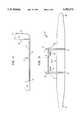
- FIG. 1is an exploded side view of the keyboard support assembly illustrating the three primary components.
- FIG. 2is a side elevational view of the keyboard support.
- FIG. 3is a rear elevational view of the keyboard support.
- FIG. 4is a front elevational view of the height adjustment member.
- FIG. 5is a side elevational view of the height member.
- FIG. 6is a front elevational view showing the cooperation between the keyboard support and the height adjustment member.
- FIG. 7is a side elevational view of the horizontal mounting member.
- FIG. 8is a rear elevational view of the horizontal mounting member.
- FIG. 9is a top elevational view of the horizontal mounting member.
- FIG. 10is a highly schematic side elevational illustrating the neutral wrist position present in the keyboard support assembly in order to avoid fatigue, tension and pain.
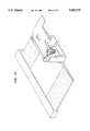
- FIG. 11is a front exploded perspective view of the keyboard support.
- FIG. 12is a rear perspective view of the keyboard support in assembled condition.
- the adjustable ergonomic keyboard support assembly 10is comprised of three (3) primary elements; the keyboard support 12, the height adjustment member 14, and the horizontal mounting member 16.
- the height adjustment member 14 and the horizontal mounting member 16together constitute a bracket assembly for mounting the keyboard support 12 to a work surface. These three elements are illustrated in FIG. 1 which is a side elevational exploded view of keyboard assembly support 10.
- the keyboard supportconsists of a planar support base 18 which generally subscribes to the shape and dimensions of a standard computer keyboard.
- Base 18has formed on its front end 20 a palm and wrist support 22.
- Palm and wrist support 22is designed to support the wrist and palm of the operator in the preferred neutral position as discussed in detail hereafter. Palm and wrist support 22 is configured to the correct height in order to provide neutral support for the operator when the computer keyboard is positioned on base 18 and its longitudinal edge is in proximate contact with the palm support and wrist 22.
- Keyboard support 12has two Upstanding parallel bracket supports 24 positioned equidistant from ends 26 and 28 of keyboard support 12. Brackets 24 are best illustrated with respect to FIG. 3 which is a rear view of keyboard support 12. Brackets 24 are designed for cooperation with height adjustment member 14. Residing between brackets 24 is a positioning rod 30 which is cooperable with a pain of vertical slots 25 and formed on height adjustment member 14 as discussed hereafter.
- locating bosses 32are in the form of horizontally-formed protrusions on the rear face of keyboard support 12 and are cooperable with complementary recesses 48 in height adjustment member 14 as described hereafter.
- the rear face of keyboard support 12has a locking cross member 34 which is rotated by actuating mechanism 36 on the front side of the rear face of keyboard support 12. As will be explained further below, through the manipulation of actuating mechanism 36, locking cross member 34 may be moved between a locked position in which it securely engages height adjustment member 14, and a released position in which it is no longer engaged with height adjustment member 14.
- actuating member 36can be operated to place locking cross member 34 in the locked position to engage locking cross member 34 with height adjustment member 14 and securely hold the components in this selected position.
- Height adjustment member 14is comprised of two (2) end brackets 40 and 42 which are spaced by channels 41 and 43, respectively, from a forward face 44. Height adjustment member 14 is generally rectangular in shape having a vertical slot 46 centrally positioned thereon, which vertical slot accommodates locking cross member 34 of keyboard support 12 in a slidable manner.
- the forward face 44 of height adjustment member 14has two rows of vertically aligned horizontal recesses 48 which in turn are cooperable with locating bosses or protrusions 32 on the rear face of keyboard support 12.
- height adjustment member 14has a second pair of vertically aligned horizontal recesses 50 positioned along the bottoms of channels 41 and 43. These recesses cooperate with complementary locating elements 52 formed on the upper rearward portions of brackets 24 of keyboard support 12.
- actuating mechanism 36maybe tuned from an opened position to a fully locked position.
- keyboard support 12may be adjusted upwardly or downwardly in relationship to height adjustment member 14 by means of the movement of guide rod 30 in vertical slots 25 and 27. This is accomplished by rotating the front edge 20 of the keyboard support upwardly with respect to height adjustment member 14. This movement disengages locating bosses 32 on keyboard support 12 from recesses 48 on the front face of height adjustment member 14, and also disengages locating elements 52 from recesses 50 in channels 41 and 43.
- Keyboard support 12may then be slidably moved upwardly or downwardly to obtain the desired height, with guide rod 30 traveling within mounting slots 25 and 27 to hold keyboard support 12 in assembled relationship with height adjustment member 14.
- FIG. 6is a front view of keyboard support 12 in cooperation with height adjustment member 14 showing the manner in which keyboard support 12 is ratchetly engaged with height adjustment member 14.
- actuating mechanism 36is positioned in the opened position (with cross member 34 oriented vertically) which would allow for the upward or downward movement of keyboard support 12. Once the correct height had been obtained, the actuating mechanism 36 would be rotated approximately 90° to the locked (shown in FIG. 11) position which in turn would cause cross member 34 to rotate to a horizontal orientation across slot 46 and into locking engagement with height adjustment member 14.
- Height adjustment member 14is cooperable with the third element of the keyboard support apparatus, namely, the horizontal mounting member 16. As illustrated in FIG. 1 and FIG. 5, a side view of height adjustment member 14, each of the parallel side bracket members 40 and 42 have extending rearwardly therefrom, an upstanding arcuate member 54 in parallel relationship with each other, each member 54 having an arcuate slot 56 formed therein, slots 56 being in parallel relationship to each other.
- FIGS. 7, 8 and 9are respectively, a side view, rear view and top view of horizontal mounting member 16.
- Horizontal mounting member 16has a generally planar upper panel 60 for cooperation with the underside of the computer stand or computer table, a pair of downwardly depending triangular sidewalls 78, and a downwardly depending front wall 79. It may be either mounted directly to the table or cooperable with a tracking system allowing for its slidable engagement under the table.
- upper panelmay have a plurality of cutouts 64 for the securing of motivating member to the underside of the computer table or stand.
- lateral edges 66 of upper panel 60could serve to position the horizontal mounting member 16 within a tracking system on the underside of the computer table.
- horizontal mounting member 16On the forward edge 68 of upper panel 60, horizontal mounting member 16 has two parallel protruding ears 70, each of which has a centrally disposed aperture 71. Ears 70 are spaced apart so as to fit in recessed corners 73 at the upper lateral edges of height adjustment member 14. In assembled position, apertures 71 in horizontal mounting member 16 are aligned with an aperture 72 extending through height adjustment member 14 between corners 73. A guide rod extending through apertures 71 and 72 holds height adjustment member 14 and horizontal mounting member 16 in assembled position while at the same time permitting the members to pivot with respect to one another.
- Height adjustment member 14may be locked in place relative to horizontal mounting member 16 by a compression locking system 76 assembled on the downwardly depending sidewalls 78 of horizontal mounting member 16.
- Compression locking system 76includes a guide rod (not shown) which is assembled at one end to one sidewall 78, and which then passes in succession through one of the arcuate slots 56 in height adjustment member 14, through an elongated bore 80 formed on the front wall 79 of horizontal mounting member 16, through the other arcuate slot 56 on height adjustment member 14, and finally through the other downwardly depending sidewall 78.
- An enlarged finger nut 81may be threadedly engaged on the free end of the guide rod.
- Tightening finger nut 81will compress arcuate members 54 on height adjustment member 14 between through bore 80 and sidewalls 78 on horizontal mounting member 16, thereby locking the height adjustment member from pivoting relative to the horizontal mounting member. As finger nut 81 is loosened, the compressive force will be diminished so that height adjustment member 14 will be free to pivot relative to horizontal mounting member 16.
- the movement of the guide rod within arcuate slot 56defines the range of this pivotable movement.
- This pivotable movementprovides for fine tuning the angular position of the keyboard support 12 and the keyboard positioned thereon vis-a-vis the operator. This is an active adjustment which is designed to accommodate the extremes and variations in the anthropomeric range indicated below.
- FIG. 10illustrates the preset negative angle of the keyboard in order to avoid stress and strain.
- Keyboard support 12is cooperative with height adjustment member 14 in a ratchet arrangement in order to selectively adjust the height.
- the keyboard support 12would come with several non-skid friction support pads 13 of various thicknesses. The operator would choose the non-skid pad 13 of such thickness to ensure that the upper surface of the keyboard keys is aligned with the upper surface of palm rest 22. In this configuration, the upper surface of the keys would be on the same plane and at the same height as the palm test.
- the operatorcan reference a laminated instructional card which details the adjustments available to the operator.
- This laminated cardis slidably cooperable with horizontal mounting member 16 so as to be recessed under the computer stand or work surface when not in use, but slidably removable by the operator in order to reference correct settings.
- the ergonomic keyboard support assembly 10when properly installed and adjusted provides a work area in which the operator is seated with the feet firmly on the floor and slightly ahead of the knees. This leg position facilitates the unrestricted blood circulation in the legs with the feet supporting the weight of the lower legs.
- the chair heightis adjusted to make the thighs nearly parallel to the floor as possible. This again avoids pressure behind the knees and promotes good blood circulation through the legs.
- the operatorwould sit rearwardly in the chair, tilted slightly from 90° vertical and well supported in the lumbar region thereby opening the body angle at the hip. This angle reduces disk pressure and relieves the muscles of the back from holding the body perfectly upright, a position that cannot be maintained for long periods of time.
- the headwould be balanced, the shoulders relaxed and the arms hanging naturally so that the hands rest comfortably on the lap. This creates an open angle at the elbow joint, again providing for proper circulation.
- This seated postureallows for the ergonomic keyboard support assembly to actually bring the work surface to the operator. It positions the keyboard lower, close to the lap where the arms can hang naturally with open angles at the elbow.
- the ergonomic keyboard support assembly 10supports the weight of the arms and keeps the wrists and hands straight and relaxed in what is referred to as a "wrist neutral position". This is accomplished by the negative angle of the keyboard support which slopes away from the user. The preset negative slope causes the hands to fall naturally into the wrist neutral position.
- the palm restsupports the fleshy portion of the hand and palm and presents a surface which allows the hands to glide freely from one end of the keyboard to the other without sticking.
- the ergonomic keyboard support assemblywhich is the subject matter of this application, provides the operator with a comfortable working environment in which proper posture is promoted and in which the hands, wrists and arms of the operator are properly supported and positioned to avoid stress and strain.
- the ergonomic keyboard assembly supportadjusts in order to bring the work, in the form of the keyboard, to the operator while the operator maintains the proper posture. While the ergonomic keyboard support assembly of the present application allows for certain adjustments to accommodate anatomical differences between operators, certain adjustments are preset, such as the negative slope of the keyboard support, so that a wrist neutral position is maintained. This negative slope is maintained regardless of the height adjustments which maybe needed to accommodate anatomical difference between operators.
Landscapes
- Input From Keyboards Or The Like (AREA)
Abstract
Description
__________________________________________________________________________Popliteal 5th % Female 95th % Male Variance Proformix Height Adj. Height: 360 mm(14.2") 485 mm(19.5") 135 mm(5") 135 mm(5") Elbow to 5th % Female 95th % Male Variance Proformix Adjustment Finger: 400 mm(15.7") 515 mm(20.3") 115 mm(4.5") >115 mm(4.5") Hand 5th % Female 95th % Male Variance Proformix Palm Rest Length: 165 mm(6.5") 210 mm(8.25") 55 mm(1.75") 80 mm(3.13") __________________________________________________________________________
Claims (17)
Priority Applications (3)
| Application Number | Priority Date | Filing Date | Title |
|---|---|---|---|
| US08/198,890US5582375A (en) | 1992-04-20 | 1994-02-18 | Adjustable ergonomic support for computer keyboards |
| PCT/US1995/002012WO1995022274A1 (en) | 1994-02-18 | 1995-02-15 | Improved adjustable ergonomic support for computer keyboards |
| US09/306,622US6148739A (en) | 1992-04-20 | 1999-05-06 | Adjustable ergonomic support for computer keyboards |
Applications Claiming Priority (2)
| Application Number | Priority Date | Filing Date | Title |
|---|---|---|---|
| US07/871,108US5351897A (en) | 1992-04-20 | 1992-04-20 | Adjustable ergonomic support for computer keyboards |
| US08/198,890US5582375A (en) | 1992-04-20 | 1994-02-18 | Adjustable ergonomic support for computer keyboards |
Related Parent Applications (1)
| Application Number | Title | Priority Date | Filing Date |
|---|---|---|---|
| US07/871,108Continuation-In-PartUS5351897A (en) | 1992-04-20 | 1992-04-20 | Adjustable ergonomic support for computer keyboards |
Related Child Applications (1)
| Application Number | Title | Priority Date | Filing Date |
|---|---|---|---|
| US73184296AContinuation | 1992-04-20 | 1996-10-21 |
Publications (1)
| Publication Number | Publication Date |
|---|---|
| US5582375Atrue US5582375A (en) | 1996-12-10 |
Family
ID=22735300
Family Applications (1)
| Application Number | Title | Priority Date | Filing Date |
|---|---|---|---|
| US08/198,890Expired - Fee RelatedUS5582375A (en) | 1992-04-20 | 1994-02-18 | Adjustable ergonomic support for computer keyboards |
Country Status (2)
| Country | Link |
|---|---|
| US (1) | US5582375A (en) |
| WO (1) | WO1995022274A1 (en) |
Cited By (42)
| Publication number | Priority date | Publication date | Assignee | Title |
|---|---|---|---|---|
| WO1998022296A1 (en)* | 1996-11-18 | 1998-05-28 | Proformix, Inc. | Keyboard support assembly incorporating cursor control device |
| US5818360A (en)* | 1997-04-28 | 1998-10-06 | Acer Incorporated | Configuration for a computer input device |
| US5899616A (en)* | 1997-10-21 | 1999-05-04 | Caplan; Leslie S. | Impact absorbing keyboard, contoured to the natural shape of the hand and method of using |
| US5924664A (en)* | 1997-03-12 | 1999-07-20 | Ergo View Technologies Corp. | Keyboard support mechanism |
| US6076785A (en)* | 1996-02-29 | 2000-06-20 | Innovative Office Products, Inc. | Ergonomic sit/stand keyboard support mechanism |
| US6092774A (en)* | 1998-11-23 | 2000-07-25 | Acco Brands, Inc. | Keyboard positioning system |
| US6116557A (en)* | 1998-07-10 | 2000-09-12 | Acco Brands, Inc. | Keyboard support system |
| US6148739A (en)* | 1992-04-20 | 2000-11-21 | 1320236 Ontario Inc. | Adjustable ergonomic support for computer keyboards |
| US6179261B1 (en)* | 1999-06-30 | 2001-01-30 | Chin-Chih Lin | Adjustable keyboard shelf |
| USD437857S1 (en) | 1999-04-20 | 2001-02-20 | Accuride International, Inc. | Pull-out keyboard tray |
| US6293508B1 (en) | 1999-01-19 | 2001-09-25 | Group Dekko Services, Llc. | Keyboard support system |
| US6419197B2 (en) | 1999-01-19 | 2002-07-16 | Group Dekko Services, Llc | Keyboard support system |
| US6454369B1 (en) | 1999-05-04 | 2002-09-24 | Accuride International, Inc. | Pull-out keyboard tray |
| US6543949B1 (en) | 2000-03-23 | 2003-04-08 | Eugene B. Ritchey | Keyboard support apparatus |
| US20030088153A1 (en)* | 1996-09-13 | 2003-05-08 | Scimed Life Systems, Inc. | Rapid exchange catheter with detachable hood |
| US20030223840A1 (en)* | 2000-06-22 | 2003-12-04 | Craig Mengel | Panel fastener |
| USD493464S1 (en) | 2003-08-19 | 2004-07-27 | William J. Kollasch | Split keyboard |
| US6772980B2 (en) | 2002-12-06 | 2004-08-10 | O'neill John M. | Ergonomic apparatus for personal computer use |
| US20040245420A1 (en)* | 2003-01-09 | 2004-12-09 | Decade Industries, Inc. | Adjustable tilt mount |
| US20050103960A1 (en)* | 2003-11-18 | 2005-05-19 | 3M Innovative Properties Company | Adjustable keyboard support assembly method of use |
| US20050105255A1 (en)* | 2003-11-18 | 2005-05-19 | 3M Innovative Properties Company | Adjustable keyboard support assembly |
| USD508918S1 (en) | 2004-04-06 | 2005-08-30 | Eugene B. Ritchey | Keyboard support |
| US20050218272A1 (en)* | 2004-04-06 | 2005-10-06 | Ritchey Eugene B | Keyboard support device and method |
| US20060065800A1 (en)* | 2004-09-29 | 2006-03-30 | Jeff Bremmon | Universal mount for flat panel displays |
| US7182533B1 (en) | 1997-10-21 | 2007-02-27 | Prosper Street Technologies, Llc | Keyboard contoured to the natural shape of the hand |
| US7395996B2 (en) | 2002-06-11 | 2008-07-08 | Csav, Inc. | Adjustable, self-balancing flat panel display mounting system |
| USD595702S1 (en) | 2008-01-04 | 2009-07-07 | Milestone Av Technologies Llc | Tilt adjustable display interface bracket |
| US7641163B2 (en) | 2005-10-21 | 2010-01-05 | Peerless Industries, Inc. | Tilt mounting system |
| USD620943S1 (en) | 2009-01-07 | 2010-08-03 | Milestone Av Technologies Llc | Single arm display mount |
| US7823847B2 (en) | 2008-01-04 | 2010-11-02 | Milestone Av Technologies Llc | Display mount with post-installation adjustment features |
| USD627787S1 (en) | 2009-01-07 | 2010-11-23 | Milestone Av Technologies Llc | Display mount with single articulating arm |
| US7866622B2 (en) | 2007-01-05 | 2011-01-11 | Milestone Av Technologies Llc | In-wall mount |
| US7891622B1 (en) | 2007-02-02 | 2011-02-22 | Peerless Industries, Inc. | Adjustable tilt mounting system |
| US8072739B2 (en) | 2007-01-03 | 2011-12-06 | Milestone Av Technologies Llc | Device mount with selectively positionable tilt axis |
| US8094438B2 (en) | 2007-01-05 | 2012-01-10 | Milestone Av Technologies Llc | Wall-avoiding self-balancing mount for tilt positioning of a flat panel electronic display |
| US20130063351A1 (en)* | 2011-09-14 | 2013-03-14 | Raghuram Reddy Talasani | Mouse |
| US20130069507A1 (en)* | 2011-09-15 | 2013-03-21 | James Dowling | Method and device for wall mounting flat panel monitor and storing associated audio/video components |
| US8891249B2 (en) | 2009-01-07 | 2014-11-18 | Milestone Av Technologies Llc | Display mount with adjustable position tilt axis |
| US8958200B2 (en) | 2008-01-04 | 2015-02-17 | Milestone Av Technologies Llc | Display mount with post-installation adjustment features |
| US9109742B2 (en) | 2008-09-02 | 2015-08-18 | Milestone Av Technologies Llc | Low profile mount for flat panel electronic display |
| US9408465B2 (en) | 2011-09-15 | 2016-08-09 | Innovative Americans, LLC | Method and device for wall mounting flat panel monitor and storing associated audio/video components |
| US20190110590A1 (en)* | 2017-10-13 | 2019-04-18 | Loctek Ergonomic Technology Corp. | Lifting platform with a sliding keyboard holder |
Families Citing this family (2)
| Publication number | Priority date | Publication date | Assignee | Title |
|---|---|---|---|---|
| DE20003296U1 (en) | 2000-02-23 | 2000-08-10 | Bührmann, Horst-Jürgen, Dipl.-Ing., 35614 Aßlar | Keyboard holder on monitor housing |
| GB2369565A (en)* | 2000-12-04 | 2002-06-05 | R C Lawrence | Table with top, or portion thereof, which slopes away from a users normal position of interaction with the table |
Citations (20)
| Publication number | Priority date | Publication date | Assignee | Title |
|---|---|---|---|---|
| US3830352A (en)* | 1972-10-02 | 1974-08-20 | Ibm | Articulated typewriter frame |
| US3991961A (en)* | 1975-03-03 | 1976-11-16 | Platzer Jr George E | Collapsible support structure |
| US4688862A (en)* | 1985-05-03 | 1987-08-25 | Marvel Metal Products Company | Workstation for electronic equipment operator |
| US4706919A (en)* | 1986-12-17 | 1987-11-17 | Haworth, Inc. | Keyboard support with automatic lowering mechanism |
| US4709972A (en)* | 1986-08-27 | 1987-12-01 | Eastman Kodak Company | Keyboard cabinet with sliding tray |
| US4913390A (en)* | 1988-09-21 | 1990-04-03 | Berke Joseph J | Portable adjustable computer keyboard support and hand rest |
| US4949650A (en)* | 1989-07-31 | 1990-08-21 | Allard David D | Table having a part of which is adjustable upwardly |
| US4976407A (en)* | 1989-12-13 | 1990-12-11 | Edtech Company | Adjustable wrist support |
| US5037054A (en)* | 1990-06-13 | 1991-08-06 | Waterloo Furniture Components Ltd. | Adjustable support mechanism for a keyboard platform |
| US5040757A (en)* | 1990-10-11 | 1991-08-20 | Benaway Dennis W | Wrist support for use with an office machine having a keyboard |
| US5048784A (en)* | 1989-12-13 | 1991-09-17 | Edtech Company | Adjustable inset bracket |
| US5073050A (en)* | 1990-06-12 | 1991-12-17 | Steffen Andrews | Ergonomic keyboard apparatus |
| US5104073A (en)* | 1990-08-15 | 1992-04-14 | Vanbeek Allen L | Arm and hand rest for a keyboard |
| WO1992013722A1 (en)* | 1991-02-01 | 1992-08-20 | Ambrose Frederic C | Keyboard positioning system |
| US5154390A (en)* | 1991-08-30 | 1992-10-13 | Bain Charles E | Articulated stand for supporting object |
| US5211367A (en)* | 1991-10-16 | 1993-05-18 | Steelcase Inc. | Single arm articulated keyboard support |
| US5257767A (en)* | 1990-06-13 | 1993-11-02 | Waterloo Furniture Components, Ltd. | Adjustable support mechanism for a keyboard platform |
| US5351897A (en)* | 1992-04-20 | 1994-10-04 | Michael Martin | Adjustable ergonomic support for computer keyboards |
| US5405204A (en)* | 1992-02-03 | 1995-04-11 | Ambrose; Frederic C. | Keyboard positioning system |
| US5513824A (en)* | 1994-03-03 | 1996-05-07 | Mead-Hatcher, Inc. | Neutral positions keyboard/wrist support |
- 1994
- 1994-02-18USUS08/198,890patent/US5582375A/ennot_activeExpired - Fee Related
- 1995
- 1995-02-15WOPCT/US1995/002012patent/WO1995022274A1/enactiveApplication Filing
Patent Citations (20)
| Publication number | Priority date | Publication date | Assignee | Title |
|---|---|---|---|---|
| US3830352A (en)* | 1972-10-02 | 1974-08-20 | Ibm | Articulated typewriter frame |
| US3991961A (en)* | 1975-03-03 | 1976-11-16 | Platzer Jr George E | Collapsible support structure |
| US4688862A (en)* | 1985-05-03 | 1987-08-25 | Marvel Metal Products Company | Workstation for electronic equipment operator |
| US4709972A (en)* | 1986-08-27 | 1987-12-01 | Eastman Kodak Company | Keyboard cabinet with sliding tray |
| US4706919A (en)* | 1986-12-17 | 1987-11-17 | Haworth, Inc. | Keyboard support with automatic lowering mechanism |
| US4913390A (en)* | 1988-09-21 | 1990-04-03 | Berke Joseph J | Portable adjustable computer keyboard support and hand rest |
| US4949650A (en)* | 1989-07-31 | 1990-08-21 | Allard David D | Table having a part of which is adjustable upwardly |
| US5048784A (en)* | 1989-12-13 | 1991-09-17 | Edtech Company | Adjustable inset bracket |
| US4976407A (en)* | 1989-12-13 | 1990-12-11 | Edtech Company | Adjustable wrist support |
| US5073050A (en)* | 1990-06-12 | 1991-12-17 | Steffen Andrews | Ergonomic keyboard apparatus |
| US5037054A (en)* | 1990-06-13 | 1991-08-06 | Waterloo Furniture Components Ltd. | Adjustable support mechanism for a keyboard platform |
| US5257767A (en)* | 1990-06-13 | 1993-11-02 | Waterloo Furniture Components, Ltd. | Adjustable support mechanism for a keyboard platform |
| US5104073A (en)* | 1990-08-15 | 1992-04-14 | Vanbeek Allen L | Arm and hand rest for a keyboard |
| US5040757A (en)* | 1990-10-11 | 1991-08-20 | Benaway Dennis W | Wrist support for use with an office machine having a keyboard |
| WO1992013722A1 (en)* | 1991-02-01 | 1992-08-20 | Ambrose Frederic C | Keyboard positioning system |
| US5154390A (en)* | 1991-08-30 | 1992-10-13 | Bain Charles E | Articulated stand for supporting object |
| US5211367A (en)* | 1991-10-16 | 1993-05-18 | Steelcase Inc. | Single arm articulated keyboard support |
| US5405204A (en)* | 1992-02-03 | 1995-04-11 | Ambrose; Frederic C. | Keyboard positioning system |
| US5351897A (en)* | 1992-04-20 | 1994-10-04 | Michael Martin | Adjustable ergonomic support for computer keyboards |
| US5513824A (en)* | 1994-03-03 | 1996-05-07 | Mead-Hatcher, Inc. | Neutral positions keyboard/wrist support |
Non-Patent Citations (14)
| Title |
|---|
| Brochure entitled "Position Control Solutions--Customize Any Workstation For Comfort & Functionality" Weber Knapp Company Copyright 1992. |
| Brochure entitled Position Control Solutions Customize Any Workstation For Comfort & Functionality Weber Knapp Company Copyright 1992.* |
| E. Helmetsie, "Mediating the Space Between Workers and Tools", Innovation, Fall 1992. |
| E. Helmetsie, Mediating the Space Between Workers and Tools , Innovation, Fall 1992.* |
| News Release entitled "New Keyboarding System Designed to Help Prevent Carpal Tunnel Syndrome Uses High-Strength, Glass-Filled Nylon for Key Structural Parts" Miles Polymers Division, Mar. 8, 1993. |
| News Release entitled New Keyboarding System Designed to Help Prevent Carpal Tunnel Syndrome Uses High Strength, Glass Filled Nylon for Key Structural Parts Miles Polymers Division, Mar. 8, 1993.* |
| O Malley, Brian, Keyboard Associated Carpal Tunnel Syndrome , date unknown, pp. 1 7.* |
| O'Malley, Brian, "Keyboard-Associated Carpal Tunnel Syndrome", date unknown, pp. 1-7. |
| Patkin, Michael, Problems of Computer Workers: Lessons from the Australian Debate, Work With Display Units 89, 1990, pp. 547 555.* |
| Patkin, Michael, Problems of Computer Workers: Lessons from the Australian Debate, Work With Display Units 89, 1990, pp. 547-555. |
| Stack, Barbara, Keyboard RSI: The Practical Solution, 1987, pp. 1 78.* |
| Stack, Barbara, Keyboard RSI: The Practical Solution, 1987, pp. 1-78. |
| Stack, Barbara, Repetitive Strain Injury Pevention and Rehabilitation, Preprints of International Conference on Ergonomics, Occupational Safety and Health and the Environment, vol. 1, Australian Darling Downs Institute of Advanced Education, 24 28th Oct., 1988, pp. 444 453.* |
| Stack, Barbara, Repetitive Strain Injury--Pevention and Rehabilitation, Preprints of International Conference on Ergonomics, Occupational Safety and Health and the Environment, vol. 1, Australian Darling Downs Institute of Advanced Education, 24-28th Oct., 1988, pp. 444-453. |
Cited By (63)
| Publication number | Priority date | Publication date | Assignee | Title |
|---|---|---|---|---|
| US6148739A (en)* | 1992-04-20 | 2000-11-21 | 1320236 Ontario Inc. | Adjustable ergonomic support for computer keyboards |
| US6076785A (en)* | 1996-02-29 | 2000-06-20 | Innovative Office Products, Inc. | Ergonomic sit/stand keyboard support mechanism |
| US20030088153A1 (en)* | 1996-09-13 | 2003-05-08 | Scimed Life Systems, Inc. | Rapid exchange catheter with detachable hood |
| WO1998022296A1 (en)* | 1996-11-18 | 1998-05-28 | Proformix, Inc. | Keyboard support assembly incorporating cursor control device |
| US6883764B1 (en) | 1997-03-12 | 2005-04-26 | Humanscale Corp. | Keyboard support mechanism |
| US5924664A (en)* | 1997-03-12 | 1999-07-20 | Ergo View Technologies Corp. | Keyboard support mechanism |
| US7841570B2 (en) | 1997-03-12 | 2010-11-30 | Humanscale Corporation | Keyboard support mechanism |
| US7841569B2 (en) | 1997-03-12 | 2010-11-30 | Humanscale Corporation | Keyboard support mechanism |
| US5818360A (en)* | 1997-04-28 | 1998-10-06 | Acer Incorporated | Configuration for a computer input device |
| US6183149B1 (en) | 1997-10-21 | 2001-02-06 | Prosper Street Technologies, L.L.C. | Impact absorbing keyboard, contoured to the natural shape of the hand |
| US7182533B1 (en) | 1997-10-21 | 2007-02-27 | Prosper Street Technologies, Llc | Keyboard contoured to the natural shape of the hand |
| US5899616A (en)* | 1997-10-21 | 1999-05-04 | Caplan; Leslie S. | Impact absorbing keyboard, contoured to the natural shape of the hand and method of using |
| US6116557A (en)* | 1998-07-10 | 2000-09-12 | Acco Brands, Inc. | Keyboard support system |
| US6092774A (en)* | 1998-11-23 | 2000-07-25 | Acco Brands, Inc. | Keyboard positioning system |
| US6293508B1 (en) | 1999-01-19 | 2001-09-25 | Group Dekko Services, Llc. | Keyboard support system |
| US6419197B2 (en) | 1999-01-19 | 2002-07-16 | Group Dekko Services, Llc | Keyboard support system |
| USD447145S1 (en) | 1999-04-20 | 2001-08-28 | Accuride International Inc. | Pull-out keyboard tray |
| USD437857S1 (en) | 1999-04-20 | 2001-02-20 | Accuride International, Inc. | Pull-out keyboard tray |
| US6454369B1 (en) | 1999-05-04 | 2002-09-24 | Accuride International, Inc. | Pull-out keyboard tray |
| US6179261B1 (en)* | 1999-06-30 | 2001-01-30 | Chin-Chih Lin | Adjustable keyboard shelf |
| US6543949B1 (en) | 2000-03-23 | 2003-04-08 | Eugene B. Ritchey | Keyboard support apparatus |
| US20030223840A1 (en)* | 2000-06-22 | 2003-12-04 | Craig Mengel | Panel fastener |
| US8490934B2 (en) | 2002-06-11 | 2013-07-23 | Milestone Av Technologies Llc | Adjustable, self-balancing flat panel display mounting system |
| US7954780B2 (en) | 2002-06-11 | 2011-06-07 | Milestone Av Technologies Llc | Adjustable self-balancing flat panel display mounting system |
| US7395996B2 (en) | 2002-06-11 | 2008-07-08 | Csav, Inc. | Adjustable, self-balancing flat panel display mounting system |
| US6772980B2 (en) | 2002-12-06 | 2004-08-10 | O'neill John M. | Ergonomic apparatus for personal computer use |
| US7178775B2 (en) | 2003-01-09 | 2007-02-20 | Csav, Inc. | Adjustable tilt mount |
| US8235342B2 (en) | 2003-01-09 | 2012-08-07 | Milestone AV Techonologies LLC | Adjustable tilt mount |
| US7152836B2 (en)* | 2003-01-09 | 2006-12-26 | Csav, Inc. | Adjustable tilt mount |
| US20040245420A1 (en)* | 2003-01-09 | 2004-12-09 | Decade Industries, Inc. | Adjustable tilt mount |
| US7438269B2 (en) | 2003-01-09 | 2008-10-21 | Csav, Inc. | Adjustable tilt mount |
| USD493464S1 (en) | 2003-08-19 | 2004-07-27 | William J. Kollasch | Split keyboard |
| US20050103960A1 (en)* | 2003-11-18 | 2005-05-19 | 3M Innovative Properties Company | Adjustable keyboard support assembly method of use |
| US7113393B2 (en) | 2003-11-18 | 2006-09-26 | 3M Innovative Properties Company | Adjustable keyboard support assembly |
| US6938866B2 (en) | 2003-11-18 | 2005-09-06 | 3M Innovative Properties Company | Adjustable keyboard support assembly method of use |
| US20050105255A1 (en)* | 2003-11-18 | 2005-05-19 | 3M Innovative Properties Company | Adjustable keyboard support assembly |
| USD508918S1 (en) | 2004-04-06 | 2005-08-30 | Eugene B. Ritchey | Keyboard support |
| US20050218272A1 (en)* | 2004-04-06 | 2005-10-06 | Ritchey Eugene B | Keyboard support device and method |
| US7108234B2 (en) | 2004-04-06 | 2006-09-19 | Ritchey Eugene B | Keyboard support device and method |
| US20060065800A1 (en)* | 2004-09-29 | 2006-03-30 | Jeff Bremmon | Universal mount for flat panel displays |
| US7641163B2 (en) | 2005-10-21 | 2010-01-05 | Peerless Industries, Inc. | Tilt mounting system |
| US8684326B2 (en) | 2005-10-21 | 2014-04-01 | Peerless Industries, Inc. | Tilt mounting system |
| US8313073B2 (en) | 2005-10-21 | 2012-11-20 | Peerless Industries, Inc. | Tilt mounting system |
| US7753332B2 (en) | 2005-10-21 | 2010-07-13 | Peerless Industries, Inc. | Tilt mounting system |
| US8157233B2 (en) | 2005-10-21 | 2012-04-17 | Peerless Industries, Inc. | Tilt mounting system |
| US8072739B2 (en) | 2007-01-03 | 2011-12-06 | Milestone Av Technologies Llc | Device mount with selectively positionable tilt axis |
| US8094438B2 (en) | 2007-01-05 | 2012-01-10 | Milestone Av Technologies Llc | Wall-avoiding self-balancing mount for tilt positioning of a flat panel electronic display |
| US8508918B2 (en) | 2007-01-05 | 2013-08-13 | Milestone Av Technologies Llc | Wall-avoiding self-balancing mount for tilt positioning of a flat panel electronic display |
| US7866622B2 (en) | 2007-01-05 | 2011-01-11 | Milestone Av Technologies Llc | In-wall mount |
| US7891622B1 (en) | 2007-02-02 | 2011-02-22 | Peerless Industries, Inc. | Adjustable tilt mounting system |
| US8958200B2 (en) | 2008-01-04 | 2015-02-17 | Milestone Av Technologies Llc | Display mount with post-installation adjustment features |
| US7823847B2 (en) | 2008-01-04 | 2010-11-02 | Milestone Av Technologies Llc | Display mount with post-installation adjustment features |
| USD595702S1 (en) | 2008-01-04 | 2009-07-07 | Milestone Av Technologies Llc | Tilt adjustable display interface bracket |
| US9109742B2 (en) | 2008-09-02 | 2015-08-18 | Milestone Av Technologies Llc | Low profile mount for flat panel electronic display |
| US8891249B2 (en) | 2009-01-07 | 2014-11-18 | Milestone Av Technologies Llc | Display mount with adjustable position tilt axis |
| USD627787S1 (en) | 2009-01-07 | 2010-11-23 | Milestone Av Technologies Llc | Display mount with single articulating arm |
| USD620943S1 (en) | 2009-01-07 | 2010-08-03 | Milestone Av Technologies Llc | Single arm display mount |
| US20130063351A1 (en)* | 2011-09-14 | 2013-03-14 | Raghuram Reddy Talasani | Mouse |
| US20130069507A1 (en)* | 2011-09-15 | 2013-03-21 | James Dowling | Method and device for wall mounting flat panel monitor and storing associated audio/video components |
| US9408465B2 (en) | 2011-09-15 | 2016-08-09 | Innovative Americans, LLC | Method and device for wall mounting flat panel monitor and storing associated audio/video components |
| US20190110590A1 (en)* | 2017-10-13 | 2019-04-18 | Loctek Ergonomic Technology Corp. | Lifting platform with a sliding keyboard holder |
| US10743655B2 (en)* | 2017-10-13 | 2020-08-18 | Loctek Ergonomic Technology Corp. | Lifting platform with a sliding keyboard holder |
| US10945520B2 (en) | 2017-10-13 | 2021-03-16 | Loctek Inc. | Lifting platform with a sliding keyboard holder |
Also Published As
| Publication number | Publication date |
|---|---|
| WO1995022274A1 (en) | 1995-08-24 |
Similar Documents
| Publication | Publication Date | Title |
|---|---|---|
| US5582375A (en) | Adjustable ergonomic support for computer keyboards | |
| US5351897A (en) | Adjustable ergonomic support for computer keyboards | |
| US5072905A (en) | Wrist and forearm support apparatus | |
| US6148739A (en) | Adjustable ergonomic support for computer keyboards | |
| US6454224B1 (en) | Forearm and wrist support assembly for keyboard user | |
| US5158256A (en) | Keyboard accessory | |
| EP0495040B1 (en) | Apparatus and method for reducing repetitive or maintained stress injuries | |
| US6357703B1 (en) | Computer mouse and arm rest | |
| US5183230A (en) | Computer keyboard support with padded wrist support | |
| US5533820A (en) | Keyboard positioning system | |
| US5112020A (en) | Keyboard stand | |
| US5845586A (en) | Ergonomic workstation | |
| US5004196A (en) | Keyboard accessory | |
| US5857415A (en) | Ergonomic computer workstation and method of using | |
| US6273382B1 (en) | Adjustable tilt-down keyboard support device | |
| US5522323A (en) | Ergonimic computer workstation and method of using | |
| US5509628A (en) | Ergonomic support for keyboard and computer mouse platform | |
| CA2291019C (en) | Keyboard support with multi-positional mouse pad | |
| US6059470A (en) | Adjustable, curved keyboard | |
| US5201485A (en) | Apparatus and method for reducing repetitive or maintained stress injuries | |
| US6935683B1 (en) | Chair arm mounted computer accessory support assembly | |
| WO1992013722A1 (en) | Keyboard positioning system | |
| US6220181B1 (en) | Ergonomic CAD (computer aided design) workstation | |
| US5961231A (en) | Keyboard positioning system | |
| US20050253028A1 (en) | Adjustable hand positioner for computer mouse |
Legal Events
| Date | Code | Title | Description |
|---|---|---|---|
| AS | Assignment | Owner name:PROFORMIX, INC., NEW JERSEY Free format text:ASSIGNMENT OF ASSIGNORS INTEREST;ASSIGNOR:MARTIN, MICHAEL G.;REEL/FRAME:007644/0668 Effective date:19950206 | |
| AS | Assignment | Owner name:PISANI, B. MICHAEL, NEW JERSEY Free format text:ASSIGNMENT OF ASSIGNORS INTEREST;ASSIGNORS:MARTING, MICHAEL G.;PROFORMIX, INC.;REEL/FRAME:008512/0616 Effective date:19970430 | |
| AS | Assignment | Owner name:CARNEGIE BANK, N.A., NEW JERSEY Free format text:SECURITY AGREEMENT;ASSIGNORS:MARTIN, MICHAEL G.;PROFORMIX, INC.;REEL/FRAME:008512/0894 Effective date:19970429 Owner name:NEW JERSEY ECONOMIC DEVELOPMENT AUTHORITY, NEW JER Free format text:SECURITY AGREEMENT;ASSIGNORS:MARTIN, MICHAEL G.;PROFORMIX, INC.;REEL/FRAME:008512/0894 Effective date:19970429 | |
| CC | Certificate of correction | ||
| AS | Assignment | Owner name:PISANI, B. MICHAEL, NEW JERSEY Free format text:CORRECTED ASSIGNMENT TO CHANGE NATURE OF CONVEYANCE FROM AN ASSIGNMENT TO A SECURITY AGREEMENT. PREVIOUSLY RECORDED ON REEL 8512, FRAME 0616.;ASSIGNORS:MARTIN, MICHAEL G.;PROFORMIX, INC.;REEL/FRAME:008650/0511 Effective date:19970430 | |
| AS | Assignment | Owner name:1320236 ONTARIO INC., CANADA Free format text:ASSIGNMENT OF ASSIGNORS INTEREST;ASSIGNOR:PROFORMIX, INC.;REEL/FRAME:009711/0370 Effective date:19981118 | |
| FPAY | Fee payment | Year of fee payment:4 | |
| FEPP | Fee payment procedure | Free format text:PAYOR NUMBER ASSIGNED (ORIGINAL EVENT CODE: ASPN); ENTITY STATUS OF PATENT OWNER: SMALL ENTITY | |
| FPAY | Fee payment | Year of fee payment:8 | |
| REMI | Maintenance fee reminder mailed | ||
| LAPS | Lapse for failure to pay maintenance fees | ||
| STCH | Information on status: patent discontinuation | Free format text:PATENT EXPIRED DUE TO NONPAYMENT OF MAINTENANCE FEES UNDER 37 CFR 1.362 | |
| FP | Lapsed due to failure to pay maintenance fee | Effective date:20081210 |