US5581687A - Interactive control systems for medical processing devices - Google Patents
Interactive control systems for medical processing devicesDownload PDFInfo
- Publication number
- US5581687A US5581687AUS08/337,639US33763994AUS5581687AUS 5581687 AUS5581687 AUS 5581687AUS 33763994 AUS33763994 AUS 33763994AUS 5581687 AUS5581687 AUS 5581687A
- Authority
- US
- United States
- Prior art keywords
- display
- interface
- region
- manager
- field
- Prior art date
- Legal status (The legal status is an assumption and is not a legal conclusion. Google has not performed a legal analysis and makes no representation as to the accuracy of the status listed.)
- Expired - Lifetime
Links
Images


Classifications
- G—PHYSICS
- G06—COMPUTING OR CALCULATING; COUNTING
- G06F—ELECTRIC DIGITAL DATA PROCESSING
- G06F3/00—Input arrangements for transferring data to be processed into a form capable of being handled by the computer; Output arrangements for transferring data from processing unit to output unit, e.g. interface arrangements
- G06F3/01—Input arrangements or combined input and output arrangements for interaction between user and computer
- G06F3/048—Interaction techniques based on graphical user interfaces [GUI]
- G06F3/0487—Interaction techniques based on graphical user interfaces [GUI] using specific features provided by the input device, e.g. functions controlled by the rotation of a mouse with dual sensing arrangements, or of the nature of the input device, e.g. tap gestures based on pressure sensed by a digitiser
- G06F3/0488—Interaction techniques based on graphical user interfaces [GUI] using specific features provided by the input device, e.g. functions controlled by the rotation of a mouse with dual sensing arrangements, or of the nature of the input device, e.g. tap gestures based on pressure sensed by a digitiser using a touch-screen or digitiser, e.g. input of commands through traced gestures
- G—PHYSICS
- G16—INFORMATION AND COMMUNICATION TECHNOLOGY [ICT] SPECIALLY ADAPTED FOR SPECIFIC APPLICATION FIELDS
- G16H—HEALTHCARE INFORMATICS, i.e. INFORMATION AND COMMUNICATION TECHNOLOGY [ICT] SPECIALLY ADAPTED FOR THE HANDLING OR PROCESSING OF MEDICAL OR HEALTHCARE DATA
- G16H40/00—ICT specially adapted for the management or administration of healthcare resources or facilities; ICT specially adapted for the management or operation of medical equipment or devices
- G16H40/60—ICT specially adapted for the management or administration of healthcare resources or facilities; ICT specially adapted for the management or operation of medical equipment or devices for the operation of medical equipment or devices
- G16H40/63—ICT specially adapted for the management or administration of healthcare resources or facilities; ICT specially adapted for the management or operation of medical equipment or devices for the operation of medical equipment or devices for local operation
- G—PHYSICS
- G16—INFORMATION AND COMMUNICATION TECHNOLOGY [ICT] SPECIALLY ADAPTED FOR SPECIFIC APPLICATION FIELDS
- G16Z—INFORMATION AND COMMUNICATION TECHNOLOGY [ICT] SPECIALLY ADAPTED FOR SPECIFIC APPLICATION FIELDS, NOT OTHERWISE PROVIDED FOR
- G16Z99/00—Subject matter not provided for in other main groups of this subclass
- A—HUMAN NECESSITIES
- A61—MEDICAL OR VETERINARY SCIENCE; HYGIENE
- A61M—DEVICES FOR INTRODUCING MEDIA INTO, OR ONTO, THE BODY; DEVICES FOR TRANSDUCING BODY MEDIA OR FOR TAKING MEDIA FROM THE BODY; DEVICES FOR PRODUCING OR ENDING SLEEP OR STUPOR
- A61M1/00—Suction or pumping devices for medical purposes; Devices for carrying-off, for treatment of, or for carrying-over, body-liquids; Drainage systems
- A61M1/02—Blood transfusion apparatus
Definitions
- the inventionrelates to control systems and user interfaces for fluid processing systems, such as blood processing systems and the like.
- microprocessorswith resident program software.
- the microprocessorsalso usually include some type of interface through which the operator views and comprehends information regarding the operation of the fluid processing systems.
- One aspect of the inventionaddresses the need for simple yet effective control systems.
- This aspectprovides an abstract, "virtual" interface between the software based applications resident in the controller and the hardware elements of the fluid processing system.
- High level process software resident in the controllercommunicates with lower level implementing process software in an instrument manager, instead of communicating directly with hardware elements.
- the intermediate instrument managerisolates or "hides” all hardware-specific commands from the high level control software.
- the data flow between the instrument manager and the hardware elements of the systemis invisible to the high level software.
- This aspect of the inventionaddresses the need for straightforward yet highly interactive user interfaces.
- This aspect of the inventionprovides an interface having two distinct viewing regions, called the status region and the working region. Preferably, the two viewing regions are fixed in relative position and unchanging in size on the interface screen. This provides continuity and consistency to the appearance of the interface, even as the functional hardware of the system cycle through different processing modes. The uniformity and consistency of the dual viewing regions of the interface reduce operator confusion and the likelihood of error.
- the status region and the working regionare each dedicated to different types and levels of information. Nevertheless, the two regions are always displayed simultaneously to provide the operator views of both high level “big picture” information (in the status region) and low level “detailed” information (in the working region).
- the two viewing regionsalso allow the operator to use the interface quickly to find and select among detailed procedures, functions, and options during system operation, or to perform off-line functions, without losing touch with the overall status of the ongoing procedure.
- the two viewing regionspermit the operator to navigate what is in reality a multiple-level menu structure to attend to details on one menu level, without necessarily moving stepwise up and down the menu structure and without losing the ability to, on command, immediately jump between higher and lower menu levels.
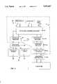
- FIG. 1is a diagrammatic view of a dual needle platelet collection system that includes a controller that embodies the features of the invention
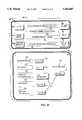
- FIG. 2is a diagrammatic flow chart view of the controller and associated interface that embodies the features of the invention
- FIG. 3is another diagrammatic view of the controller and associated interface shown in FIG. 2, and further showing the command and status flow hierarchy;
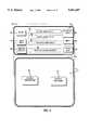
- FIG. 4is a view of the dual region interface that embodies the features of the invention, showing the block and touch activated fields that the interface contains;
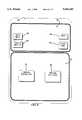
- FIG. 5is a view of the interface shown in FIG. 4 when in a full screen mode
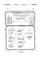
- FIG. 6is a diagrammatic view of the detection and display of abnormal function conditions by the controller shown in FIGS. 2 and 3;
- FIG. 7is a view of the dual region interface in an alarm condition
- FIG. 8is a view of the dual region interface in a system start-up default condition, showing the Main Menu in the working region of the interface screen;
- FIG. 9is a view of the condition of the interface screen with the HELP button activated in the status region when the Main Menu is active in the working region of the screen;
- FIG. 10is a view of the dual region interface, showing the Select Procedures SubMenu in the working region of the interface screen;
- FIG. 11is a view of the dual region interface, showing the installation instructions for the install mode in the working region of the interface screen;
- FIG. 12is a view of the dual region interface, showing the detailed procedures display for the collection mode in the working region of the interface screen;
- FIG. 13is a view of the dual region interface, showing the edit/modify screen for the detailed procedures display in the working region of the interface screen during the collection mode;
- FIG. 14is a view of the dual region interface, showing the Main Menu in the working region of the interface screen during the collection mode;
- FIG. 15is a view of the dual region interface, showing the Special Features SubMenu in the working region of the interface screen during the collection mode;
- FIG. 16is a view of the dual region interface, with the detailed procedures display for the collection mode in the working region, and a return occlusion alarm in the status region;
- FIG. 17is a view of the dual region interface, with the instructions for correcting the return occlusion alarm in the working region during the collection mode.
- FIG. 1shows in diagrammatic form a fluid processing system 10.
- the system 10can be used for processing various fluids.
- the system 10is particularly well suited for processing fluids for medical purposes, like whole blood and other suspensions of biological cellular materials. Accordingly, the illustrated embodiment shows the system 10 used for this purpose.
- the system 10includes an arrangement of durable hardware elements,
- the hardware elementswill vary according to the nature and type of processing system.
- the hardware elementswill include a centrifuge 12, in which whole blood (WB) is separated into its various therapeutic components, like platelets, plasma, and red blood cells (RBC).
- WBwhole blood
- RBCred blood cells
- the hardware elementswill also include various pumps, which are typically peristaltic (designated P1 to P4); and various in line clamps and valves (designated V1 to V3).
- P1 to P4peristaltic
- V1 to V3various in line clamps and valves
- FIG. 1does not show, like solenoids, pressure monitors, and the like.
- the system 10typically also includes some form of a disposable fluid processing assembly 14 used in association with the hardware elements.
- the assembly 14includes a two stage processing chamber 16.
- the centrifuge 12rotates the processing chamber 16 to centrifugally separate blood components.
- the construction of the two stage processing chamber 16can vary. For example, it can take the form of double bags, like the processing chambers shown in Cullis et al. U.S. Pat. No. 4,146,172. Alternatively, the processing chamber 16 can take the form of an elongated two stage integral bag, like that shown in Brown U.S. Patent x,xxx,xxx.
- thee processing assembly 14also includes an array of flexible tubing that forms a fluid circuit.
- the fluid circuitconveys liquids to and from the processing chamber 16.
- the pumps P1-P4 and the valves V1-V3engage the tubing to govern the fluid flow in prescribed ways.
- the fluid circuitfurther includes a number of containers (designated C1 to C3) to dispense and receive liquids during processing.
- a controller 18governs the operation of the various hardware elements to carry out one or more processing tasks using the assembly 14.
- the inventionspecifically concerns important attributes of the controller 18.
- FIG. 1shows the system 10 configured to carry out an automated two needle platelet collection procedure.
- a first tubing branch 20 and the whole blood inlet pump P2direct WB from a draw needle 22 into the first stage 24 of the processing chamber 16. Meanwhile, an auxiliary tubing branch 26 meters anticoagulant from the container C1 to the WB flow through the anticoagulant pump P1.
- the container C2holds saline solution.
- Another auxiliary tubing branch 28conveys the saline into the first tubing branch 20, via the in line valve V1, for use in priming and purging air from the system 10 before processing begins. Saline solution is also introduced again after processing ends to flush residual components from the assembly 14 for return to the donor.
- Anticoagulated WBenters and fills the first stage 24 of the processing chamber 24. There, centrifugal forces generated during rotation of the centrifuge 12 separate WB into red blood cells (RBC) and platelet-rich plasma (PRP).
- RBCred blood cells
- PRPplatelet-rich plasma
- the PRP pump P4operates to draw PRP from the first stage 24 of the processing chamber 16 into a second tubing branch 30 for transport to the second stage 32 of the processing chamber 16. There, the PRP is separated into platelet concentrate (PC) and platelet-poor plasma (PPP).
- PCplatelet concentrate
- PPPplatelet-poor plasma
- the system 10includes a recirculation tubing branch 34 and an associated recirculation pump P3.
- the processing controller 18operates the pump P3 to divert a portion of the PRP exiting the first stage 24 of the processing chamber 16 for remixing with the WB entering the first stage 24 of the processing chamber 16.
- the illustrated two needle systemsimultaneously returns RBC from the first chamber stage 24, along with a portion of the PPP from the second chamber stage 32, to the donor through a return needle 36 through tubing branches 38 and 40 and in line valve V2.
- the system 10also collects PC in some of the containers C3 through tubing branches 38 and 42 and in line valve V3 for storage and therapeutic use.
- the system 10can also collect PPP in some of the containers C3 through the same fluid path.
- the controller 18carries out the overall process control and monitoring functions for the system 10 as just described.
- the controllercomprises a main processing unit (MPU) 44.
- MPU 44comprises a type 68030 microprocessor made by Motorola Corporation, although other types of conventional microprocessors can be used.
- the MPU 44employs conventional real time multi-tasking to allocate MPU cycles to processing tasks.
- a periodic timer interrupt(for example, every 5 milliseconds) preempts the executing task and schedules another that is in a ready state for execution. If a reschedule is requested, the highest priority task in the ready state is scheduled. Otherwise, the next task on the list in the ready state is scheduled.
- the MPU 44includes an application control manager 46.
- the application control manager 46administers the activation of a library 48 of control applications (designated A1 to A3).
- Each control application A1-A3prescribes procedures for carrying out given functional tasks using the system hardware (e.g., the centrifuge 12, the pumps P1-P4, and the valves V1-V3) in a predetermined way.
- the applications A1-A3reside as process software in EPROM's in the MPU 44.
- the number of applications A1-A3can vary.
- the library 48includes at least one clinical procedure application A1.
- the procedure application A1contains the steps to carry out one prescribed clinical processing procedure.
- the library 48includes a procedure application A1 for carrying out the dual needle platelet collection process, as already generally described in connection with FIG. 1.
- additional procedure applicationscan be, and typically will be, included.
- the library 48can include a procedure application for carrying out a conventional single needle platelet collection process.
- the library 48also includes at least one additional, non-procedure application.
- the non-clinical procedural applicationcontains the procedures to carry out a system configuration or support utility.
- the library 48includes a configuration application A2, which contains the procedures for allowing the operator to configure the default operating parameters of the system 10.
- the library 48also includes a main menu application A3, which coordinates the selection of the various applications A1-A3 by the operator, as will also be described in greater detail later.
- the library 48can include a diagnosis application, which contains the procedures aiding service personnel in diagnosing and troubleshooting the functional integrity of the system, and a system restart application, which performs a full restart of the system, should the system become unable to manage or recover from an error condition.
- a diagnosis applicationwhich contains the procedures aiding service personnel in diagnosing and troubleshooting the functional integrity of the system
- a system restart applicationwhich performs a full restart of the system, should the system become unable to manage or recover from an error condition.
- An instrument manager 50also resides as process software in EPROM's in the MPU 44.
- the instrument manager 50communicates with the application control manager 46.
- the instrument manager 50also communicates with low level peripheral controllers 52 for the pumps, solenoids, valves, and other functional hardware of the system.
- the application control manager 46sends specified commands in abstract form to the instrument manager 50, as called up by the activated application A1-A3.
- the instrument manager 50identifies the peripheral controller or controllers 52 for performing the function and compiles hardware-specific commands (that will be referred to herein as "Operate -- Hardware# commands") into the command tables for the particular peripheral controllers 52.
- the peripheral controllers 52communicate directly with the hardware to implement the hardware-specific commands generated by the instrument manager 50, causing the hardware to operate in a specified way to carry out the abstract Perform -- Function# commands.
- a communication manager 54manages low-level protocol and communications between the instrument manager 50 and the peripheral controllers 52.
- the instrument manager 50also conveys back to the application control manager 46 status data about the operational and functional conditions of the processing procedure.
- the status datais expressed in terms of, for example, fluid flow rates, sensed pressures, and fluid volumes measured.
- the application control manager 46processes and uses the status data in various ways. In one way, the application control manager 46 transmits selected status data for display to the operator, as will be described later. In another way, the application control manager 46 monitors operational and functional conditions using the status data to detect abnormal system conditions requiring operator intervention or system shutdown, as will also be described in greater detail later.
- the MPU 44also includes a condition manager 56 that resides in the data flow path between the instrument manager 50 and the communications manager 54.
- the condition manager 56also monitors status data and other operational states of the hardware to detect abnormal conditions that are either not detected or are left uncorrected by the application control manager 46. Upon detecting such abnormal conditions, the condition manager 56 provides fail-safe support by suspending system operation. Further details of this fail-safe function and other related aspects of the controller 18 will be described later.
- the described control hierarchycreates an abstract, "virtual" interface between the applications resident in the application control manager 46 and the hardware elements of the system 10.
- the high level process software resident in the application control manager 46communicates with lower level implementing process software in the instrument manager 50, instead of communicating directly with hardware elements.
- the intermediate instrument manager 50isolates or "hides” all hardware-specific commands from the application control manager 46.
- the applicationspass abstract Perform -- Function# commands to the instrument manager 50, and the instrument manager 50 converts these abstract commands into the specific Operate -- Hardware# commands unique to the particular hardware elements, all without further participation by the procedure applications A1-A3 themselves.
- the data flow between the instrument manager 50 and the hardware elements of the system 10is invisible to the activated application A1-A3.
- the instrument manager 50forms a part of the same MPU in which the application control manager 46 resides.
- the instrument manager 50can reside on a separate processing unit.
- the MPU 44also includes an interactive user interface 58.
- the interface 58allows the operator to view and comprehend information regarding the operation of the system 10.
- the interface 58also allows the operator to select applications residing in the application control manager 46, as well as to change certain functions and performance criteria of the system 10.
- the interface 58includes an interface screen 60 and, preferably, an audio device 62.
- the interface screen 60displays information for viewing by the operator in alpha-numeric format and as graphical images.
- the audio device 62provides audible prompts either to gain the operator's attention or to acknowledge operator actions.
- the interface screen 60also serves as an input device. It receives input from the operator by conventional touch activation, as will be described later. Alternatively or in combination with touch activation, a mouse or keyboard could be used as input devices.
- An interface controller 64communicates with the interface screen 60 and audio device 62.
- the interface controller 64in turn, communicates with an interface manager 66, which in turn communicates with the application control manager 46.
- the interface controller 64 and the interface manager 66reside as process software in EPROM's in the MPU 44.
- the application control manager 46sends to the interface manager 66 specified field values reflecting selected status data received from the instrument manager 50.
- the application control manager 46also sends to the interface manager 66 prescribed abstract Create -- Display# and Create -- Audio# commands called for by the activated application.
- the interface manager 66processes these field values and the abstract Create -- Display# commands to generate specific Format -- Display# commands.
- the Format -- Display# commandscontrol the particular format, attributes, and protocols necessary to create, refresh, and close the visual display on the interface screen 60.
- the interface manager 66processes the abstract Create -- Audio# commands to generate specific Format -- Audio# commands.
- the Format -- Audio# commandsdictate the format and attributes of the audio output called for by the activated application.
- the interface manager 66conveys the processed Format -- Display# and -- Audio# commands to the interface controller 64.
- the interface controller 64provides low level control functions that draw boxes and lines, forms text or graphical characters, and provides the formatting attributes of the display on the interface screen 60.
- the interface controller 64also provides low level control functions that drive the audio device 62 based upon Format -- Audio# commands received from the interface manager 66.
- the interface controller 64also accepts Field# -- Select commands generated by touch activation of the interface screen 60, as will be described in greater detail later.
- the interface controller 64passes this touch activated input to the interface manager 66 in the form of Touch# -- Codes.
- the interface manager 66processes the Touch# -- Codes to the application control manager 46, either as function codes or as changed field values.
- the application control manager 46implements the function codes or changed field values and passes them to the instrument manager 50. Further details of this will be provided later.
- This control hierarchyalso creates an abstract, "virtual" interface between the functional processors of the controller 18 and the interface 58.
- the high process software of the interface manager 66isolates and “hides” all formatting and protocol issues used in creating the interface 58 from the applications used to control hardware functions of the system 10.
- the process software of the applications A1-A3, through the application control manager 46,pass abstract field values and Create -- Display# and Create -- Audio# commands to the interface manager 66.
- the process software of the interface manager 66converts these abstract commands into the specific commands that control the textual and graphic formats and audio formats of the operator interface 58, without further participation by the procedure applications A1-A3 themselves.
- the data flow between the interface manager 66 and the interface controller 64is invisible to the data flow between the application control manager 46 and the instrument manager 50.
- This control hierarchylends further flexibility in adding or modifying applications for controlling hardware functions. New or modified applications need only to include textual field value outputs and the prescribed Create -- Display# or Create -- Audio# commands to gain immediate linkage to the operator interface.
- the Format -- Display# commands of the interface manager 66formats information for display on the interface screen 60 in two distinct viewing regions, called the status region 68 and the working region 70.
- the two viewing regions 68 and 70are fixed in relative position and unchanging in size on the interface screen 60. This provides continuity and consistency to the appearance of the interface 58, even as the functional hardware of the system cycle through different processing modes. The uniformity and consistency of the dual viewing regions 68 and 70 of the interface 58 reduce operator confusion and the likelihood of error.
- the status region 68 and the working region 70are each dedicated to different types and levels of information. Nevertheless, the two regions 68 and 70 are always displayed simultaneously to provide the operator views of both high level "big picture” information and low level “detailed” information.
- the working region 70provides the means for the operator to select and activate any one of the system-resident applications A1-A3.
- the working region 70displays all specific procedure-dependent information then called for by the Create -- Display# commands generated by the activated application A1-A3.
- the considerable detail of information displayed in the working region 70allows the operator to monitor and change the ongoing process in real time.
- the status region 68continuously shows prescribed procedure-dependent information of a more general and "overview" nature, about which an operator routinely needs continuous knowledge and immediate access.
- the status region 68continuously displays this general information to keep the operator appraised of the overall status of the ongoing process, even when the operator is using the working region 70 to monitor and change more detailed aspects of the processes.
- the status region 68also provides means for the operator to respond to alarms or malfunctions.
- the two viewing regions 68 and 70allow the operator to use the interface 58 quickly to find and select among detailed procedures, functions, and options during system operation, or to perform off-line functions, without losing touch with the overall status of the ongoing procedure.
- the two viewing regions 68 and 70permit the operator to navigate what is in reality a multiple-level menu structure to attend to details on one menu level, without necessarily moving stepwise up and down the menu structure and without losing the ability to, on command, immediately jump between higher and lower menu levels.
- the viewing regions 68 and 70are vertically separated by a graphical line or line of characters 72, with the status region 68 occupying the upper one-third of the screen 60 and the working region 70 occupying the lower two-thirds of the screen 60. It should be appreciated, however, that the viewing regions 68 and 70 could be separated horizontally in a side by side relationship, and occupy differing proportions of the screen 60.
- the status region 68 and the working region 70display information in fields.
- the Format -- Display# for the particular display that the interface manager 66 generatesis composed of a list of such fields specifying, for each field, its location, size, and type in the region and the format of information it contains.
- the fieldscan formatted as individual touch selectable buttons.
- the fieldscan also be formatted as an array of touch selectable button fields, which present a field of choices to the operator.
- the fieldscan also be formatted as blocks comprising alpha or numeric data strings, or textual data comprising multiple lines of line-wrapped, scrollable text, or graphic images.
- the fieldscan also be formatted to be bar graph fields, which display numeric format in graphical form.
- the interface manager 66includes constant (ROM-based) structures in look-up table form that store data describing the layout and formatting of all display attributes, including regions, field type, and field location within the regions.
- the interface manager 66stores dynamic (RAM-based) structures that describe the present state of the interface display.
- the interface manager 66Upon receiving a given Create -- Display# command from the activated application, the interface manager 66 examines the ROM-based table structures and the RAM-based status structures to create or update the RAM-based status structures, as called for by the activated application.
- the interface manager 66includes a time-triggered task routine that performs all operations required to periodically update screen 60 and audio outputs. The interface manager 66 sends this processed information to the interface controller 64 for implementation.
- the interface manager 66also holds a Function# -- Code associated with each touch selectable button field identified by the Touch# -- Code received from the interface controller 64.
- the Function# -- Codesare arranged in constant (ROM-based) look-up table form according to region and field location within the region, as identified by the Touch# -- Code.
- the interface controller 64registers the region and field location when a given button is touched, passing this information in the form of a Touch# -- Code to the interface manager 66.
- the interface manager 66includes a process button utility that awaits and asynchronously processes this information by examining the ROM-based table structure and sending the appropriate Function# -- Code to the application control manager 46 for implementation.
- FIG. 4shows a preferred implementation.
- the status region 68includes a three blocks fields 74/76/78 that provide general status information about the procedure then being run.
- the MAJOR MODE field 74contains the description of the clinical procedure activated.
- the procedureis "Dual Needle Platelet Collection," or any other application selected by the user and resident in the application control manager 46.
- the MINOR MODE field 76contains a one or two word description of the procedure status. For example, for a Dual Needle Platelet Collection, the MINOR MODE field 76 can sequentially display an install mode (for installing disposable elements on the hardware elements); a system check mode (for checking hardware operation before beginning processing); a prime mode (for removing air from the system before processing); a collection mode (for collecting whole blood for processing); a flush and reinfusion mode (for removing residual components from the system for return to the donor after processing); and a so-called wrap-up mode (for removing disposable elements from the hardware elements after processing).
- an install modefor installing disposable elements on the hardware elements
- a system check modefor checking hardware operation before beginning processing
- a prime modefor removing air from the system before processing
- a collection modefor collecting whole blood for processing
- a flush and reinfusion modefor removing residual components from the system for return to the donor after processing
- wrap-up modefor removing disposable elements from the hardware elements after processing.
- the WB PROCESSED field 78contains the amount of blood drawn from the donor through the draw pump P2 during processing, expressed numerically in units of ml.
- the WB PROCESSED field 78is displayed when the dual needle procedure enters the collection mode and remains displayed until the procedure has ended or is terminated.
- the status region 68also includes an array of touch selectable button fields 80/82/84/86.
- the individual button fields 80/82/84/86when touched, each cause the interface manager 66 to transmit a prescribed function code for implementation by the application control manager 46.
- the touch selection of a given button fielddoes not alter the display of information in the blocks fields 74/76/78 on the status region 68. Any change in the interface 58 resulting from touch selection of a given button in the status region 68 typically occurs in the working region 70.
- the HELP button field 80calls up a context-sensitive function that displays in the working region 70 general, largely qualitative information regarding the procedure status displayed in the MINOR MODE field 76.
- the MENU button field 82calls up a function that causes activation of the main menu application and the resulting display of the Main Menu in the working region 70 (as FIG. 4 shows as a default condition). As will be described in greater detail later, the Main Menu allows the operator to select for activation any application A1-A3 managed by the application control manager 46.
- the PROCEDURE DISPLAY button 84 fieldcalls up a function that displays in the working region 70 the display of specific procedure-dependent information then called for the activated procedure application.
- the MENU button field 82 and the PROCEDURE DISPLAY button field 84 in the status region 68together make possible the rapid selection of other non-clinical procedure applications while a given clinical procedure application runs, while retaining the ability to immediately return to the particular display of specific procedure-dependent information then called for by the activated clinical procedure, without the need to progress up and down through a menu tree structure or to find one's place in a sequence of menus that are intended to lead the operator stepwise through the procedure from start to finish.
- the PAUSE/END button field 86calls up a function that immediately pauses any currently operating clinical procedure application.
- the buttoncalls for the display in the working region 70 of the display of specific procedure-dependent information called for by the activated procedure at the time that the PAUSE/END button 86 is activated.
- the working region 70 displayalso preferable includes a RESUME touch activated button field or an END touch activated button field, to give the operator the choice of continuing with the procedure or halting it.
- the block fields 74/76/78occupy fixed locations in the center of the status region 68.
- the MENU button field 82 and the PROCEDURE DISPLAY button field 84occupy fixed locations on the left side, middle and bottom positions, of the status region 68, respectively.
- the HELP button field 80occupies a fixed location on the right side, middle position, of the status region 68.
- the PAUSE/END button field 86occupies a fixed location on the right side, bottom position, of the status region 68.
- the status region 68also includes context-dependent NOTE/WARNING PROMPT button field 88 that occupies a fixed location on the right side, top position, of the status region 68 when an alarm or warning is active.
- the NOTE/WARNING PROMPT button field 88is not displayed when an alarm or warning is not active.
- a MUTE button field 90also occupies a fixed location on the left side, top position, of the status region 68 when an alarm is active.
- a WARNING/ALARM block fieldalso occupies a fixed location on the center, bottom position, of the status region when an alarm is active. Further details of the alarms and the NOTE/WARNING PROMPT and MUTE buttons 88 and 90 and the WARNING ALARM block filed 92 will be described later.
- the working region 70shows by default the Main Menu display called for by the main menu application A3.
- the Main Menu displayincludes an array of touch selectable button fields 94 and 96, labeled CHOOSE PROCEDURE and SPECIAL FEATURES.
- the CHOOSE PROCEDURE button field 94calls up a function that displays a Procedure Submenu in the working region 70.
- the Procedure Submenulists in an array of touch selectable button fields all clinical procedure applications administered by the application control manager 46, which in the illustrated implementation is the Dual Needle Procedure Application A1.
- a procedure application button fieldcalls up a function that directs the application control manager 46 to activate the associated application.
- the activated applicationgenerates its own designated Create -- Display# commands, which the interface manager 66 implements to change the display in the working region 70. Further details of this will be provided later.
- the SPECIAL FEATURES button field 96calls up a function that displays a Special Features Submenu in the working region 70.
- the Features Submenulists in an array of touch selectable button fields designed non-clinical procedure specific applications administered by the application control manager 46, which in the illustrated implementation is the Configure System Procedure Application A2.
- a given special procedures application buttonis touched, that application is activated and the display in the working region 70 changes in response to the Create -- Display# commands of the activated application. Further details of this will be provided later.
- the interface manager 66In the preferred implementation, only one display is active at any given time in the status and working regions 68 and 70. The operator can make input selections using the active display, and the interface manager 66 up dates and refreshes the active display with real time information received from the activated application.
- the interface manager 66includes additional RAM-based memory to preformat frequently used displays before displaying them. Such "virtual displays" remain inactive until called for an activated application or by a callable function.
- the interface manager 66also supports a full screen 60 mode (see FIG. 5), which can be enabled or disabled by any particular application.
- the interface screen 60includes a single textual or graphical block field 98 forming single display region.
- the full screen modecan be used, for example, during system start-up, initialization, and some; diagnostic modes.
- the following exampleillustrates the operation of the dual region interface.
- FIG. 8shows the default condition of the dual region interface screen 60 that embodies the features of the invention, as it exists before the selection of a procedure application.
- the status region 68is thus free of the MAJOR MODE, MINOR MODE, WB PROCESSED, and BLOCK WARNING/ALARM fields 74/76/78/92 (see FIG. 4 for comparison).
- the MUTE and WARNING/NOTE button fields 88 and 90are also empty.
- the working region 70shows the Main Menu, showing a CHOOSE PROCEDURE button field 94 and a SPECIAL FEATURES button field 96 already described.
- FIG. 9shows the condition of the dual region interface screen 60, after the operator has selected the HELP button field 80 in the status region 68.
- the status region 68shows no change.
- a textual field 102has been opened in the working region 70, overlying and hiding the Main Menu.
- the textual field 102provides general information about the Main Menu and the selection options available in the Main Menu and in the status region 68.
- touch selecting the MAIN MENU button 82 in the status region 68the operator immediately returns to the Main Menu in the working region 70, as FIG. 8 shows.
- FIG. 10shows the condition of the dual region interface screen 60, after the operator has selected the CHOOSE PROCEDURE button field 94 in the working region 70.
- the status region 68shows no change.
- the working region 70shows in button fields 104 and 106 the clinical procedure applications resident in the application control manager 46.
- a button field 104 labeled the Dual Needle Platelet Procedureis shown for activating the application A1.
- Additional button fieldswould also exist (for example, a Single Needle Platelet Procedure button field 106, as shown) equal in number to the number of procedure applications residing in the application control manager 46.
- FIG. 11shows the condition of the dual region interface screen 60, after the operator has selected the Dual Needle Platelet button field 104 in the working region 70.
- the status region 68shows in the MAJOR MODE field 74 that the Dual Needle Platelet Collection Procedure has been selected.
- the Status region 68also shows in the MINOR MODE field 76 that the procedure is in the install mode.
- the status regionshows in the WB PROCESSED FIELD 78 that no whole blood has been collected yet.
- the working region 70shows in the textual field 108 instructions for the operator to follow in installing the disposable elements on the hardware elements.
- the working region 70also shows a touch activated CONTINUE button field 110 which, when touched, causes the instructions in the textual field 108 to progress, taking the operator stepwise through the installation procedure until complete.
- the MINOR MODE field 76 in the status region 68changes as the activated procedure progresses through successive modes including a check of hardware functionality, priming of the fluid flow paths to remove air, procedure start-up, and venipuncture tasks, either automatically or with the assistance of the operator.
- the textual field 108 in the working region 70also changes to display information, as appropriate, to prompt the operator to take steps to aid in accomplishing these tasks. In all other respects, the other visual aspects of the status region 68 and working region 70 remain unchanged.
- FIG. 12shows the condition of the dual region interface screen 60, when the procedure enters the collection mode.
- whole bloodis drawn from the donor, centrifugally separated into component parts, and its components either returned to the donor or collected, as earlier described.
- the Status region 68continuously shows in the MINOR MODE field 76 that the procedure is in the collection mode.
- the status regioncontinuously shows in the WB PROCESSED FIELD 78 the volume of WB drawn from the donor.
- the location and attributes of the other button fields 80/82/84/86remain unchanged, unless the procedure changes operational mode, at which time the MINOR MODE field 76 will change to reflect this mode change.
- the working region 70continuously shows in an array of prescribed textual block fields 112 and associated prescribed touch activated button fields 114 selected field values detailing the progress of the ongoing procedure.
- the type of information selected by the procedure application for display as a field value in the working region 70 during the collection modecan vary.
- the block fields 112list by way of example the donor weight, the anticoagulant (AC) ratio, the rate of infusing citrate carried by the PPP returned to the donor, the volume of PPP collected for resuspending collected PC, the amount of additional PPP collected as a by-product, and the amount of whole blood yet to be processed to meet the PC yield selected for the procedure.
- the associated button fields 114contain the current status of these operational factors, which are displayed as field values within the button fields 114.
- Field values in the button field 114change to reflect changes in the current status, when they occur. For example, the amount of WB to be processed decrements over time toward zero. When the WB to process button field 114 is zero, the application prompts the operator to begin the flush and reinfusion mode.
- FIG. 13shows the condition of the display screen 60 when, for example, the operator touch selects the WB TO PROCESS button field 114 in the working region 70 to change the volume of whole blood to be processed during the procedure.
- the working region 70 displaychanges to display a touch activated numeric keypad 116, along with block fields 118 showing the field value to be changed, it present value, and the units in which it is expressed.
- touch activating the keypad 116the operator changes and enters the new value, then selects the touch activated Return button field 120 to return to the working display 70 shown in FIG. 12.
- the field value in the WB TO PROCESS button field 114will reflect the new field value.
- the status region 68 displayremains visible and unchanged, except to reflect changes in the volume of whole blood processed during the edit/modify procedure or any change in operational mode called for by the activated application.
- FIG. 14shows the condition of the display screen 60 should the operator make this choice after having completed the exit/modify procedure just described.
- the working region 70 of the screenchanges to show the Main Menu.
- the status region 68 displayremains visible and unchanged, reflecting the status information at the time the MENU button field 82 was activated by the operator, except to reflect ongoing changes in the volume of blood processed (as a comparison of FIG. 14 to FIG. 12 shows) or a change in operational mode.
- FIG. 15shows the condition of the display screen when this selected is made. As FIG. 15 shows, the working region 70 of the screen 68 changes to show the Features Submenu.
- the Features Submenulists in an array of touch selectable button fields 122, 124, and 126 the non-procedure specific applications administered by the application control manager 46.
- Touch button field 122activates the Configure System Procedure Application A2.
- FIG. 15assumes that additional non-clinical procedural applications are also resident in the application control manager 46, such as the diagnosis application (which touch button field 124 activates) and system restart application (which touch button field 126 activates), as previously discussed.
- the status region 68 displayremains visible and unchanged as the working region 70 display changes to show the Features Submenu.
- the status region 68continues to reflect the status information at the time the SPECIAL FEATURES button field 96 was activated by the operator, except to reflect ongoing changes in the volume of blood processed (as a comparison of FIG. 15 to FIG. 14 shows) or changes in the operational mode.
- the operatormay proceed to touch select a given button field 122, 124, 126 in the working region 70 shown in FIG. 15.
- the selected button fieldwill activate the associated application.
- the status region 68remains visible and unchanged, except to reflect status changes in the information fields it contains.
- the operatormay choose to again view detailed status information about the clinical procedure then being implemented (as shown in the MINOR MODE field 76). To do so, the operator need only to touch select the PROCEDURE DISPLAY field button 84, which remains continuously visible and accessible at all times to the operator in the status region 68.
- the working region 70 displayreturns to the format and attributes shown in FIG. 12 (if the process is still in the collection mode), or whatever the format or attributes of the procedure display is for the mode identified in the MINOR MODE field 76.
- the status region 68keeps the operator continuously informed as to the "big picture" as the working region 70 changes to provide access to the details of processing.
- the status region 68also provides the means for the operator to quickly jump through the multiple-level menu structure of the interface 58, to attend to details on one menu level, without necessarily moving stepwise up and down the menu structure and without losing the ability to, on command, immediately jump between higher and lower menu levels.
- the MINOR MODE field 76changes to reflect mode changes made under the control of the activated application.
- the procedureprompts the operator to enter the RBC flush and reinfusion mode, during which residual RBC are flushed and returned to the donor.
- the procedurethen enters a Procedure Wrap Up mode, in which the operator is instructed to remove the disposable components.
- Each procedure application(see FIG. 6) defines abnormal functional and operational states that require operator awareness and/or operator intervention.
- the procedure application A1processes status data received from the instrument manager 50 to determine whether any; current operating condition constitutes a prescribed abnormal functional state. If so, the application control manager 46 issues prescribed commands to notify the operator through the user interface 58 and, under certain conditions, suspend system operation.
- the MPU 44also includes the condition manager 56 to provide fail-safe support to error detection functions of the application control manager 46.
- the condition manager 56can reside in an auxiliary processing unit (APU) (for example, a second type 68030 microprocessor), or partly in the MPU 44 and partly in an APU.
- APUauxiliary processing unit
- the condition manager 56contains a list defining abnormal functional and operational states. Some of the defined states in the condition manager 56 are the same as the states defined in the application control manager 46, while others are independent cross checks of hardware control commands and status data to verify hardware integrity that only the condition manager 56 undertakes.
- the condition manager 56monitors the flow of data between the instrument manager 50 and the peripheral hardware controllers 54 (shown in FIG. 2) to determine whether any current operating condition meets the criteria defined for an abnormal functional state.
- the condition manager 56preferably includes a time-out period for conditions that the application control manager 46 also monitors, to thereby allow the application control manager 46 a period of time to correct the abnormal state.
- condition manager 56continuously sends an OK -- State status to the application control manager 46 as long as no current operating condition constitutes a defined abnormal functional state, or as long as the time-out period for a sensed abnormal functional state, if applicable, has not lapsed.
- condition manager 56When the condition manager 56 detects a current operating condition that meets the criteria defined for an abnormal functional state, and if the time-out period, if applicable, has lapsed, the condition manager 56 sends a Not -- OK -- State# status to the application control manager 46.
- the Not -- OK -- State# statusidentifies to the application control manager 46 the abnormal condition detected.
- the application control manager 46Upon receipt of the Not -- OK -- State# status from the condition manager 56, and regardless whether the activated procedure application also detects the same abnormal functional state, the application control manager 46 issues prescribed commands to notify the operator through the user interface 58.
- control manager 56Upon issuing a Not -- OK -- State# status, the control manager 56 goes fail-safe, suspending system operation and interrupting all further communication between the application control manager 46 and the peripheral controllers 52 until the abnormal state is corrected.
- the application control manager 46categorizes defined abnormal functional and operational states either as an alarm condition or as an attention condition.
- the alarm conditionscomprise functional and operational states requiring immediate operator intervention.
- the attention conditionscomprise functional and operational conditions that may be transient and self-correcting over time, or that otherwise do not require immediate operator intervention.
- the application control manager 46automatically upgrades an attention condition that remains uncorrected for a prescribed period of time after detection (for example, 2 minutes) to an alarm condition.
- the application control manager 46also automatically treats a Not -- OK -- State# status from the condition manager 56 as an alarm condition.
- abnormal operational statesthat can be treated as alarm conditions include pump motor direction error; pump motor speed error; liquid spill detected inside the centrifuge; centrifuge rotor imbalance; control voltage power failure; centrifuge door open; centrifuge door not locked; empty anticoagulant container.
- abnormal operational statesthat can be treated as alarm conditions include temperature in centrifuge above limit; weight scale limits exceeded; and anticoagulant level low.
- FIG. 6shows, upon detection of a condition that represents an alarm condition, the application control manager 46 generates and transmits a prescribed Create -- Alarm# -- Display command to the interface manager 66. Likewise, upon detection of condition that represents an attention state, the application control manager 46 generates and transmits a prescribed Create -- Note# -- Display command to the interface manager 66.
- the interface manager 66Upon receipt of a prescribed Create -- Alarm# or -- Note# -- Display, the interface manager 66 examines the ROM-based table structures and the RAM-based status structures to create or update the display codes to implement the designation display and audio through the interface controller 64 using the interface screen 60 and audio device 62.
- the interface manager 66places all displays generated in response to Create -- Alarm# -- Display or Create -- Note# -- Display commands initially in the status region 68 of the interface screen 60, as FIG. 4 shows.
- the interface manager 66reserves the top position on the left and right sides and the bottom center position of the status region 68 for the alarm and note fields 88/90/92. These positions on the status region 68 remain free of any display character or indicia in the absence of a sensed alarm or attention condition.
- the interface manager 66creates the touch selectable, button field 88 (see FIG. 4) on the right side, top position, of the status region 68.
- the button field 88is colored red (the international alarm color) and contains the word "Warning" or some other word or words to denote a sense of urgency.
- the interface manager 66also creates the touch selectable mute button field 90 on the left side, top position, when an alarm state is active. Touch selection of the mute button field 90 turns off a prescribed time period any audible alarm associated with the alarm state.
- the interface manager 66creates the alarm block field 92 at the bottom of the status region 68.
- the block field 92also preferably colored red and bar-shaped, contains a description of the warning condition of appropriate length.
- the interface manager 66removes the button field 88 and the block field 92 from the status region 68 and displays in a textual field 100 in the working region 70 more detailed information regarding the appropriate responses for the operator to follow in correcting the sensed alarm state.
- the alarm state of the activated procedure applicationmaintains control over the working region 70 of the interface, allowing no display except those relating to the alarm state and associated corrective measures to be active, until the condition manager 56 and the application control manager 46 sense the removal of the alarm state.
- the interface manager 66creates the touch selectable, button field 88 on the right side, top position, of the status region 68 (see FIG. 4).
- the button field 88in an attention state, is colored yellow or another cautionary color distinguishable from the color of the button field 88 in an alarm condition.
- the button field 88contains the word "Note” or some other cautionary word or words readily distinguishable from the word contained in the field 88; when in an alarm state.
- the interface manager 66also creates the touch selectable mute button field 90 on the left side, top position, when an attention state is active. Touch selection of the mute button field 90 turns off a prescribed time period any audible alarm associated with the attention state.
- the interface manager 66creates the block field 92 at the bottom middle of the status region 68.
- the block field 92preferably colored the same color as the note alarm button field and bar-shaped, contains a description of the attention condition of appropriate length.
- the interface manager 66removes the block field from the status region 68 and displays in the textual field 100 (see FIG. 7) in the working region 70 more detailed information and regarding the appropriate responses for the operator to follow in correcting the sensed attention state, if appropriate.
- the attention state of the activated procedure applicationmaintains control over the working region 70 of the interface, allowing no display except those relating to the attention state and associated corrective measures to be active, until the condition manager 56 and the application control manager 46 sense the removal of the attention state.
- the alarm/note fields 88 and 92relate only to a single alarm or note condition at the same time. There are never multiple displays of these fields at a given time, even when multiple Create -- Alarm# -- Display and/or Create -- Note# -- Display commands are received.
- the user interface manager 66stacks the multiple commands in an alarm queue and an attention que as received. The user interface manager 66 and implements the commands for display one at a time, on a first-in, first-out basis, except that an alarm state takes precedence over any attention state.
- the following exampleillustrates the operation of the interface when an alarm/attention condition is sensed.
- FIG. 16shows the condition of the interface screen 60 should an occlusion in the tubing branch 40 (see FIG. 1) returning RBC and PPP to the donor be sensed by the application control manager 46 in the manner described above.
- FIG. 16assumes that, at the time that occlusion is detected, the screen 60 had a display like that shown in FIG. 12.
- the display in the status region 68changes to include the button field 88, which is displayed in red to designate an alarm state (as contrasted with an attention state).
- the status region 68also changes to show the block field 92, which is also in red, and which contains text identifying the nature of the alarm (Return Occlusion Detected).
- the status region 68also shows the MUTE button field 90, allowing the operator to mute any audible alarm called for by the application control manager 46 for the identified alarm state.
- the working region 70continues to show the display that was active at the time the alarm condition was detected.
- FIG. 17shows the condition of the screen 70 after the operator touch selects the alarm field button 88.
- the display in the status region 68changes by the removal of the alarm button field 88 and associated block field 92.
- the display in the working region 70changes to show the text block field 100 (also shown in FIG. 7) containing information about the detected alarm condition and suggested ways of correcting it.
- the working region 70also includes touch selected button fields 128 and 130.
- the button field 128allows the operator to resume the procedure, once the alarm condition is corrected.
- the button field 130gives the operator the option of ending the procedure.
- the working region 70 of the display screen 60Upon correcting the alarm condition and touch selection of the button field 128, the working region 70 of the display screen 60 returns to the display that was active at the time the alarm condition was first displayed, which in the illustrated embodiment would be FIG. 12.
- the specific computer code used for implementing the applications A1-A3, the application control manager 46, the instrument manager 56, condition manager 56, the interface manager 66, and the interface controller 64depends upon the computer language being used and the preferences of the programmer.
- the procedures and commands described in this specificationcan all be written by normally skilled programmers in various conventional langauges, like C; Pascal; PLM; ADA; and multiple tasking BASIC, based upon the descriptions provided herein.
- Appendix Aincludes illustrative functional requirements in a preferred implementation of an interactive user interface that embodies features of the invention.
Landscapes
- Engineering & Computer Science (AREA)
- Health & Medical Sciences (AREA)
- Biomedical Technology (AREA)
- Theoretical Computer Science (AREA)
- General Engineering & Computer Science (AREA)
- Epidemiology (AREA)
- Physics & Mathematics (AREA)
- Medical Informatics (AREA)
- Primary Health Care (AREA)
- Public Health (AREA)
- General Business, Economics & Management (AREA)
- Human Computer Interaction (AREA)
- General Health & Medical Sciences (AREA)
- General Physics & Mathematics (AREA)
- Business, Economics & Management (AREA)
- External Artificial Organs (AREA)
- User Interface Of Digital Computer (AREA)
- Investigating Or Analysing Biological Materials (AREA)
- Measurement Of The Respiration, Hearing Ability, Form, And Blood Characteristics Of Living Organisms (AREA)
- Digital Computer Display Output (AREA)
- Manipulator (AREA)
Abstract
Description
Claims (6)
Priority Applications (13)
| Application Number | Priority Date | Filing Date | Title |
|---|---|---|---|
| US08/337,639US5581687A (en) | 1994-11-10 | 1994-11-10 | Interactive control systems for medical processing devices |
| CA002179621ACA2179621C (en) | 1994-11-10 | 1995-05-15 | Interactive control systems for medical processing devices |
| EP95920509AEP0739511B1 (en) | 1994-11-10 | 1995-05-15 | Interactive control systems for medical processing devices |
| AU25940/95AAU698378B2 (en) | 1994-11-10 | 1995-05-15 | Interactive control systems for medical processing devices |
| JP51601796AJP4081587B2 (en) | 1994-11-10 | 1995-05-15 | Interactive control system for medical treatment equipment |
| DE69535863TDE69535863D1 (en) | 1994-11-10 | 1995-05-15 | INTERACTIVE CONTROL SYSTEMS FOR MEDICAL PROCESSING EQUIPMENT |
| PCT/US1995/006241WO1996015489A1 (en) | 1994-11-10 | 1995-05-15 | Interactive control systems for medical processing devices |
| US08/680,437US5956023A (en) | 1994-11-10 | 1996-07-15 | Interactive control systems for medical processing devices |
| US09/595,536US6363290B1 (en) | 1994-11-10 | 2000-06-16 | Interactive control systems for medical processing devices |
| US09/855,901US6542910B2 (en) | 1994-11-10 | 2001-05-15 | Systems and methods for storing, retrieving, and manipulating data in medical processing devices |
| US10/038,919US20020056672A1 (en) | 1994-11-10 | 2002-01-03 | Interactive control systems for medical processing devices |
| US10/375,288US20030131026A1 (en) | 1994-11-10 | 2003-02-27 | Systems and methods for storing, retrieving, and manipulating data in medical processing devices |
| JP2007319807AJP2008149136A (en) | 1994-11-10 | 2007-12-11 | Interactive control system for medical processing devices |
Applications Claiming Priority (1)
| Application Number | Priority Date | Filing Date | Title |
|---|---|---|---|
| US08/337,639US5581687A (en) | 1994-11-10 | 1994-11-10 | Interactive control systems for medical processing devices |
Related Child Applications (1)
| Application Number | Title | Priority Date | Filing Date |
|---|---|---|---|
| US08/680,437ContinuationUS5956023A (en) | 1994-11-10 | 1996-07-15 | Interactive control systems for medical processing devices |
Publications (1)
| Publication Number | Publication Date |
|---|---|
| US5581687Atrue US5581687A (en) | 1996-12-03 |
Family
ID=23321376
Family Applications (4)
| Application Number | Title | Priority Date | Filing Date |
|---|---|---|---|
| US08/337,639Expired - LifetimeUS5581687A (en) | 1994-11-10 | 1994-11-10 | Interactive control systems for medical processing devices |
| US08/680,437Expired - Fee RelatedUS5956023A (en) | 1994-11-10 | 1996-07-15 | Interactive control systems for medical processing devices |
| US09/595,536Expired - Fee RelatedUS6363290B1 (en) | 1994-11-10 | 2000-06-16 | Interactive control systems for medical processing devices |
| US10/038,919AbandonedUS20020056672A1 (en) | 1994-11-10 | 2002-01-03 | Interactive control systems for medical processing devices |
Family Applications After (3)
| Application Number | Title | Priority Date | Filing Date |
|---|---|---|---|
| US08/680,437Expired - Fee RelatedUS5956023A (en) | 1994-11-10 | 1996-07-15 | Interactive control systems for medical processing devices |
| US09/595,536Expired - Fee RelatedUS6363290B1 (en) | 1994-11-10 | 2000-06-16 | Interactive control systems for medical processing devices |
| US10/038,919AbandonedUS20020056672A1 (en) | 1994-11-10 | 2002-01-03 | Interactive control systems for medical processing devices |
Country Status (7)
| Country | Link |
|---|---|
| US (4) | US5581687A (en) |
| EP (1) | EP0739511B1 (en) |
| JP (2) | JP4081587B2 (en) |
| AU (1) | AU698378B2 (en) |
| CA (1) | CA2179621C (en) |
| DE (1) | DE69535863D1 (en) |
| WO (1) | WO1996015489A1 (en) |
Cited By (74)
| Publication number | Priority date | Publication date | Assignee | Title |
|---|---|---|---|---|
| US5653887A (en)* | 1995-06-07 | 1997-08-05 | Cobe Laboratories, Inc. | Apheresis blood processing method using pictorial displays |
| US5689704A (en)* | 1994-03-04 | 1997-11-18 | Sony Corporation | Recording medium, recording/playback device which uses commands in character string form for audio system control |
| US6200287B1 (en) | 1997-09-05 | 2001-03-13 | Gambro, Inc. | Extracorporeal blood processing methods and apparatus |
| US6211887B1 (en) | 1998-05-28 | 2001-04-03 | Ericsson Inc | System and method for data visualization |
| US6256643B1 (en)* | 1998-03-10 | 2001-07-03 | Baxter International Inc. | Systems and methods for storing, retrieving, and manipulating data in medical processing devices |
| US6315707B1 (en) | 1999-09-03 | 2001-11-13 | Baxter International Inc. | Systems and methods for seperating blood in a rotating field |
| US6322488B1 (en) | 1999-09-03 | 2001-11-27 | Baxter International Inc. | Blood separation chamber with preformed blood flow passages and centralized connection to external tubing |
| US6324588B1 (en)* | 1997-04-02 | 2001-11-27 | Motorola, Inc. | User interface control software for a communication device |
| US20020077241A1 (en)* | 1999-09-03 | 2002-06-20 | Baxter International Inc. | Blood processing systems and methods with quick attachment of a blood separation chamber to a centrifuge rotor |
| WO2002088897A2 (en) | 2001-04-28 | 2002-11-07 | Baxter International Inc. | A system and method for managing a procedure in a blood component collection facility |
| US20020177799A1 (en)* | 1996-01-31 | 2002-11-28 | John Rivera | Apparatus for sequestering platelet rich plasma |
| US6497674B1 (en)* | 1995-06-07 | 2002-12-24 | Gambro, Inc. | Extracorporeal blood processing methods and apparatus |
| US6524231B1 (en) | 1999-09-03 | 2003-02-25 | Baxter International Inc. | Blood separation chamber with constricted interior channel and recessed passage |
| US6582386B2 (en) | 2001-03-06 | 2003-06-24 | Baxter International Inc. | Multi-purpose, automated blood and fluid processing systems and methods |
| US6587728B2 (en) | 2001-03-30 | 2003-07-01 | Neurocontrol Corporation | Systems and methods for performing prosthetic or therapeutic neuromuscular stimulation using an external, battery powered controller with power conservation features |
| US20030135152A1 (en)* | 2000-09-27 | 2003-07-17 | Kollar Kevin J. | Disposable cartridge for a blood perfusion system |
| US6625494B2 (en) | 2001-03-30 | 2003-09-23 | Neurocontrol Corporation | Systems and methods for performing prosthetic or therapeutic neuromuscular stimulation using a universal external controller providing different selectable neuromuscular stimulation functions |
| US20030204416A1 (en)* | 2002-04-30 | 2003-10-30 | Sayeh Radpay | System and method for facilitating time-based infusion orders |
| US6678563B2 (en) | 2001-03-30 | 2004-01-13 | Neurocontrol Corporation | Systems and methods for performing prosthetic or therapeutic neuromuscular stimulation using a universal external controller having a graphical user interface |
| US20040019464A1 (en)* | 2002-01-29 | 2004-01-29 | Martucci James P. | System and method for identifying data streams associated with medical equipment |
| US6695803B1 (en) | 1998-10-16 | 2004-02-24 | Mission Medical, Inc. | Blood processing system |
| US6701189B2 (en) | 2001-03-30 | 2004-03-02 | Neurocontrol Corporation | Systems and methods for performing prosthetic or therapeutic neuromuscular stimulation using a universal external controller accommodating different control inputs and/or different control outputs |
| US6706008B2 (en) | 2001-03-06 | 2004-03-16 | Baxter International Inc. | Automated system and method for withdrawing compounds from blood |
| US20040078231A1 (en)* | 2002-05-31 | 2004-04-22 | Wilkes Gordon J. | System and method for facilitating and administering treatment to a patient, including clinical decision making, order workflow and integration of clinical documentation |
| US20040082459A1 (en)* | 2002-10-24 | 2004-04-29 | Baxter International Inc. | Blood processing systems and methods for collecting plasma free or essentially free of cellular blood components |
| US20040082458A1 (en)* | 1999-09-03 | 2004-04-29 | Baxter International Inc. | Blood processing systems and methods with umbilicus-driven blood processing chambers |
| US6730054B2 (en) | 1999-10-16 | 2004-05-04 | Baxter International Inc. | Blood collection systems and methods that derive estimated effects upon the donor's blood volume and hematocrit |
| US6730055B2 (en) | 2000-03-09 | 2004-05-04 | Gambro Inc. | Extracorporeal blood processing methods and apparatus |
| US6790195B2 (en) | 1995-06-07 | 2004-09-14 | Gambro Inc | Extracorporeal blood processing methods and apparatus |
| US6808503B2 (en) | 2001-03-06 | 2004-10-26 | Baxter International Inc. | Automated system and method for pre-surgical blood donation and fluid replacement |
| US20040236387A1 (en)* | 1998-06-03 | 2004-11-25 | Neurocontrol Corporation | Treatment of shoulder dysfunction using a percutaneous intramuscular stimulation system |
| US6884228B2 (en) | 2001-03-06 | 2005-04-26 | Baxter International Inc. | Automated system adaptable for use with different fluid circuits |
| US6890291B2 (en) | 2001-06-25 | 2005-05-10 | Mission Medical, Inc. | Integrated automatic blood collection and processing unit |
| US6985870B2 (en) | 2002-01-11 | 2006-01-10 | Baxter International Inc. | Medication delivery system |
| US7037428B1 (en) | 2002-04-19 | 2006-05-02 | Mission Medical, Inc. | Integrated automatic blood processing unit |
| US7297272B2 (en) | 2002-10-24 | 2007-11-20 | Fenwal, Inc. | Separation apparatus and method |
| US20080027368A1 (en)* | 2000-09-27 | 2008-01-31 | Sorin Group Usa, Inc. | Disposable cartridge for a blood perfusion system |
| US20080209357A1 (en)* | 2005-06-09 | 2008-08-28 | Gambro Lundia Ab | Medical Apparatus and Method for Setting Up a Medical Apparatus |
| US20080249377A1 (en)* | 2005-08-25 | 2008-10-09 | Gambro Lundia Ab | Medical Apparatus |
| US20080307353A1 (en)* | 2005-08-25 | 2008-12-11 | Gambro Lundia Ab | Medical Apparatus and User Interface for a Medical Apparatus |
| US20080314289A1 (en)* | 2007-06-20 | 2008-12-25 | Pham Nam D | Polyester amide copolymers having free carboxylic acid pendant groups |
| US20100036454A1 (en)* | 1998-06-03 | 2010-02-11 | Ndi Medical, Llc. | Systems and methods to place one or more leads in muscle for providing electrical stimulation to treat pain |
| US8234128B2 (en) | 2002-04-30 | 2012-07-31 | Baxter International, Inc. | System and method for verifying medical device operational parameters |
| US8775196B2 (en) | 2002-01-29 | 2014-07-08 | Baxter International Inc. | System and method for notification and escalation of medical data |
| US20140235421A1 (en)* | 2011-09-21 | 2014-08-21 | Beckman Coulter, Inc. | Centrifuge, centrifuge system and method |
| EP2778994A1 (en) | 2013-03-15 | 2014-09-17 | Fenwal, Inc. | Systems, articles of manufacture, and methods for multi-screen visualization and instrument configuration |
| US9248446B2 (en) | 2013-02-18 | 2016-02-02 | Terumo Bct, Inc. | System for blood separation with a separation chamber having an internal gravity valve |
| US9677042B2 (en) | 2010-10-08 | 2017-06-13 | Terumo Bct, Inc. | Customizable methods and systems of growing and harvesting cells in a hollow fiber bioreactor system |
| US9733805B2 (en) | 2012-06-26 | 2017-08-15 | Terumo Bct, Inc. | Generating procedures for entering data prior to separating a liquid into components |
| US10016554B2 (en) | 2008-07-09 | 2018-07-10 | Baxter International Inc. | Dialysis system including wireless patient data |
| US10061899B2 (en) | 2008-07-09 | 2018-08-28 | Baxter International Inc. | Home therapy machine |
| US10076663B2 (en) | 2010-11-11 | 2018-09-18 | Spr Therapeutics, Inc. | Systems and methods for the treatment of pain through neural fiber stimulation |
| US10173008B2 (en) | 2002-01-29 | 2019-01-08 | Baxter International Inc. | System and method for communicating with a dialysis machine through a network |
| US10347374B2 (en) | 2008-10-13 | 2019-07-09 | Baxter Corporation Englewood | Medication preparation system |
| US10552577B2 (en) | 2012-08-31 | 2020-02-04 | Baxter Corporation Englewood | Medication requisition fulfillment system and method |
| US10646405B2 (en) | 2012-10-26 | 2020-05-12 | Baxter Corporation Englewood | Work station for medical dose preparation system |
| US10722715B2 (en) | 2010-11-11 | 2020-07-28 | Spr Therapeutics, Inc. | Systems and methods for the treatment of pain through neural fiber stimulation |
| EP3695859A1 (en) | 2010-02-19 | 2020-08-19 | Fenwal, Inc. | Authorization scheme to minimize the use of unauthorized medical device disposables on a medical device instrument |
| US10818387B2 (en) | 2014-12-05 | 2020-10-27 | Baxter Corporation Englewood | Dose preparation data analytics |
| US10857361B2 (en) | 2010-11-11 | 2020-12-08 | Spr Therapeutics, Inc. | Systems and methods for the treatment of pain through neural fiber stimulation |
| US10971257B2 (en) | 2012-10-26 | 2021-04-06 | Baxter Corporation Englewood | Image acquisition for medical dose preparation system |
| US11107574B2 (en) | 2014-09-30 | 2021-08-31 | Baxter Corporation Englewood | Management of medication preparation with formulary management |
| US11367533B2 (en) | 2014-06-30 | 2022-06-21 | Baxter Corporation Englewood | Managed medical information exchange |
| US11385769B2 (en) | 2014-03-31 | 2022-07-12 | Gambro Lundia Ab | Extracorporeal blood treatment flow rate adjustment |
| US11495334B2 (en) | 2015-06-25 | 2022-11-08 | Gambro Lundia Ab | Medical device system and method having a distributed database |
| US11516183B2 (en) | 2016-12-21 | 2022-11-29 | Gambro Lundia Ab | Medical device system including information technology infrastructure having secure cluster domain supporting external domain |
| US11540973B2 (en) | 2016-10-21 | 2023-01-03 | Spr Therapeutics, Llc | Method and system of mechanical nerve stimulation for pain relief |
| US11575673B2 (en) | 2014-09-30 | 2023-02-07 | Baxter Corporation Englewood | Central user management in a distributed healthcare information management system |
| US11624046B2 (en) | 2017-03-31 | 2023-04-11 | Terumo Bct, Inc. | Cell expansion |
| US11629332B2 (en) | 2017-03-31 | 2023-04-18 | Terumo Bct, Inc. | Cell expansion |
| US11667881B2 (en) | 2014-09-26 | 2023-06-06 | Terumo Bct, Inc. | Scheduled feed |
| US11948112B2 (en) | 2015-03-03 | 2024-04-02 | Baxter Corporation Engelwood | Pharmacy workflow management with integrated alerts |
| US11965175B2 (en) | 2016-05-25 | 2024-04-23 | Terumo Bct, Inc. | Cell expansion |
| US12412644B2 (en) | 2014-10-24 | 2025-09-09 | Baxter Corporation Englewood | Automated exchange of healthcare information for fulfillment of medication doses |
Families Citing this family (86)
| Publication number | Priority date | Publication date | Assignee | Title |
|---|---|---|---|---|
| US5915379A (en)* | 1997-03-14 | 1999-06-29 | Nellcor Puritan Bennett Incorporated | Graphic user interface for a patient ventilator |
| DE19742637C5 (en)* | 1997-09-26 | 2005-06-02 | Fresenius Medical Care Deutschland Gmbh | Device and method for operating medical devices |
| JP2001525940A (en)* | 1998-03-10 | 2001-12-11 | バクスター インターナショナル インコーポレイテッド | System and method for monitoring and analyzing the operation of a medical processing device |
| US6577899B2 (en) | 2000-01-21 | 2003-06-10 | Medtronic Minimed, Inc. | Microprocessor controlled ambulatory medical apparatus with hand held communication device |
| US7430478B2 (en) | 2000-03-01 | 2008-09-30 | Caridian Bct, Inc. | Blood processing information system with blood loss equivalency tracking |
| EP1238361A1 (en)* | 2000-03-01 | 2002-09-11 | Gambro, Inc. | Extracorporeal blood processing information management system |
| JP4691085B2 (en)* | 2000-03-14 | 2011-06-01 | 株式会社東芝 | MRI system center apparatus and clinical protocol providing method |
| EP1589456A1 (en) | 2000-03-14 | 2005-10-26 | Kabushiki Kaisha Toshiba | Mri system center and mri system |
| KR20020070359A (en)* | 2000-10-17 | 2002-09-06 | 코닌클리케 필립스 일렉트로닉스 엔.브이. | Method of controlling an arrangement of hardware components |
| US7320120B2 (en)* | 2000-12-20 | 2008-01-15 | Microsoft Corporation | Pluggable notations and semantics for visual modeling elements |
| US7103527B2 (en)* | 2000-12-20 | 2006-09-05 | Microsoft Corporation | Negotiated interconnection of visual modeling elements |
| US20020075290A1 (en)* | 2000-12-20 | 2002-06-20 | Microsoft Corporation | Incremental and interruptible layout of visual modeling elements |
| US6795089B2 (en) | 2000-12-20 | 2004-09-21 | Microsoft Corporation | Dynamic, live surface and model elements for visualization and modeling |
| JP4125616B2 (en)* | 2002-04-15 | 2008-07-30 | 日機装株式会社 | Blood purification equipment |
| US6982038B2 (en) | 2002-06-14 | 2006-01-03 | Medtronic, Inc. | Centrifuge system utilizing disposable components and automated processing of blood to collect platelet rich plasma |
| KR100559730B1 (en)* | 2003-09-22 | 2006-03-15 | 삼성전자주식회사 | Method and apparatus for data encoding / decoding for recording system |
| US7263406B2 (en) | 2003-10-02 | 2007-08-28 | Medtronic, Inc. | Medical device programmer with selective disablement of display during telemetry |
| US7396324B2 (en)* | 2003-10-17 | 2008-07-08 | Hitachi Koki Co., Ltd. | Centrifugal separator with first and second control panels |
| DE102004026561B4 (en) | 2004-05-27 | 2007-02-22 | Fresenius Medical Care Deutschland Gmbh | Hemodialysis machine with emergency activator |
| US20060226086A1 (en)* | 2005-04-08 | 2006-10-12 | Robinson Thomas C | Centrifuge for blood processing systems |
| US20090048959A1 (en)* | 2006-03-29 | 2009-02-19 | Kei Omura | Share map display apparatus, share map display system, and program for the same |
| US8273049B2 (en) | 2007-02-27 | 2012-09-25 | Deka Products Limited Partnership | Pumping cassette |
| US7794141B2 (en)* | 2006-04-14 | 2010-09-14 | Deka Products Limited Partnership | Thermal and coductivity sensing systems, devices and methods |
| US10537671B2 (en) | 2006-04-14 | 2020-01-21 | Deka Products Limited Partnership | Automated control mechanisms in a hemodialysis apparatus |
| US9717834B2 (en) | 2011-05-24 | 2017-08-01 | Deka Products Limited Partnership | Blood treatment systems and methods |
| US8366316B2 (en)* | 2006-04-14 | 2013-02-05 | Deka Products Limited Partnership | Sensor apparatus systems, devices and methods |
| JP5519276B2 (en)* | 2006-06-16 | 2014-06-11 | プロメガ・コーポレーション | Biological sample processing equipment to select the type of characteristic of the equipment |
| US20120165685A1 (en)* | 2010-12-22 | 2012-06-28 | Weasler Marc N | Plasmapheresis donor display and method of use |
| US20090107335A1 (en) | 2007-02-27 | 2009-04-30 | Deka Products Limited Partnership | Air trap for a medical infusion device |
| US8042563B2 (en) | 2007-02-27 | 2011-10-25 | Deka Products Limited Partnership | Cassette system integrated apparatus |
| US10463774B2 (en) | 2007-02-27 | 2019-11-05 | Deka Products Limited Partnership | Control systems and methods for blood or fluid handling medical devices |
| US8562834B2 (en) | 2007-02-27 | 2013-10-22 | Deka Products Limited Partnership | Modular assembly for a portable hemodialysis system |
| US9028691B2 (en) | 2007-02-27 | 2015-05-12 | Deka Products Limited Partnership | Blood circuit assembly for a hemodialysis system |
| US8409441B2 (en) | 2007-02-27 | 2013-04-02 | Deka Products Limited Partnership | Blood treatment systems and methods |
| WO2010027437A2 (en)* | 2007-02-27 | 2010-03-11 | Deka Products Limited Partnership | Blood treatment systems and methods |
| KR102444304B1 (en) | 2007-02-27 | 2022-09-19 | 데카 프로덕츠 리미티드 파트너쉽 | hemodialysis system |
| US8393690B2 (en) | 2007-02-27 | 2013-03-12 | Deka Products Limited Partnership | Enclosure for a portable hemodialysis system |
| US8357298B2 (en) | 2007-02-27 | 2013-01-22 | Deka Products Limited Partnership | Hemodialysis systems and methods |
| US8491184B2 (en) | 2007-02-27 | 2013-07-23 | Deka Products Limited Partnership | Sensor apparatus systems, devices and methods |
| US8425471B2 (en) | 2007-02-27 | 2013-04-23 | Deka Products Limited Partnership | Reagent supply for a hemodialysis system |
| US8231578B2 (en)* | 2007-02-28 | 2012-07-31 | Hospira, Inc. | System and method for sequencing channels in a multi-channel infusion pump |
| US8409124B2 (en)* | 2007-03-08 | 2013-04-02 | Medronic, Inc. | Blood pump system user interface alarm management |
| US8374929B1 (en) | 2007-08-06 | 2013-02-12 | Gogrid, LLC | System and method for billing for hosted services |
| US8771508B2 (en) | 2008-08-27 | 2014-07-08 | Deka Products Limited Partnership | Dialyzer cartridge mounting arrangement for a hemodialysis system |
| US9026370B2 (en) | 2007-12-18 | 2015-05-05 | Hospira, Inc. | User interface improvements for medical devices |
| US8708950B2 (en) | 2010-07-07 | 2014-04-29 | Deka Products Limited Partnership | Medical treatment system and methods using a plurality of fluid lines |
| JP5595930B2 (en)* | 2008-01-23 | 2014-09-24 | デカ・プロダクツ・リミテッド・パートナーシップ | Disposable components for fluid line automatic connection systems |
| US9078971B2 (en) | 2008-01-23 | 2015-07-14 | Deka Products Limited Partnership | Medical treatment system and methods using a plurality of fluid lines |
| US9186075B2 (en) | 2009-03-24 | 2015-11-17 | Covidien Lp | Indicating the accuracy of a physiological parameter |
| CN104841030B (en) | 2009-10-30 | 2017-10-31 | 德卡产品有限公司 | For the apparatus and method for the disconnection for detecting intravascular access device |
| PL2504045T3 (en) | 2009-11-24 | 2020-11-16 | Fresenius Medical Care Deutschland Gmbh | Method for temporarily interrupting an extracorporeal blood treatment, control device and blood treatment device |
| US20110132368A1 (en) | 2009-12-04 | 2011-06-09 | Nellcor Puritan Bennett Llc | Display Of Historical Alarm Status |
| US9526920B2 (en) | 2010-10-12 | 2016-12-27 | Smith & Nephew, Inc. | Medical device |
| EP3205362B1 (en) | 2011-05-24 | 2022-07-06 | DEKA Products Limited Partnership | Hemodialysis system |
| AU2012299169B2 (en) | 2011-08-19 | 2017-08-24 | Icu Medical, Inc. | Systems and methods for a graphical interface including a graphical representation of medical data |
| JP6027129B2 (en) | 2011-11-04 | 2016-11-16 | デカ・プロダクツ・リミテッド・パートナーシップ | Medical systems that use multiple fluid lines |
| JP2012040445A (en)* | 2011-12-02 | 2012-03-01 | Terumo Corp | Peritoneal dialysis device |
| US10022498B2 (en) | 2011-12-16 | 2018-07-17 | Icu Medical, Inc. | System for monitoring and delivering medication to a patient and method of using the same to minimize the risks associated with automated therapy |
| US8856668B2 (en)* | 2011-12-22 | 2014-10-07 | Fresenius Medical Care Holdings, Inc. | Drug delivery devices and related systems and methods |
| JP6306566B2 (en) | 2012-03-30 | 2018-04-04 | アイシーユー・メディカル・インコーポレーテッド | Air detection system and method for detecting air in an infusion system pump |
| AU2013296555B2 (en) | 2012-07-31 | 2017-10-19 | Icu Medical, Inc. | Patient care system for critical medications |
| AU2013201566B2 (en) | 2012-08-31 | 2014-11-27 | Gambro Lundia Ab | Dialysis apparatus with versatile user interface and method and computer program therefor |
| US9737649B2 (en) | 2013-03-14 | 2017-08-22 | Smith & Nephew, Inc. | Systems and methods for applying reduced pressure therapy |
| JP2016517318A (en) | 2013-03-14 | 2016-06-16 | スミス アンド ネフュー インコーポレーテッド | System and method for administering decompression therapy |
| AU2014268355B2 (en) | 2013-05-24 | 2018-06-14 | Icu Medical, Inc. | Multi-sensor infusion system for detecting air or an occlusion in the infusion system |
| US10166328B2 (en) | 2013-05-29 | 2019-01-01 | Icu Medical, Inc. | Infusion system which utilizes one or more sensors and additional information to make an air determination regarding the infusion system |
| WO2014194065A1 (en) | 2013-05-29 | 2014-12-04 | Hospira, Inc. | Infusion system and method of use which prevents over-saturation of an analog-to-digital converter |
| WO2015023515A1 (en) | 2013-08-13 | 2015-02-19 | Smith & Nephew, Inc. | Systems and methods for applying reduced pressure therapy |
| EP3110474B1 (en) | 2014-02-28 | 2019-12-18 | ICU Medical, Inc. | Infusion system and method which utilizes dual wavelength optical air-in-line detection |
| US10235333B1 (en)* | 2014-04-11 | 2019-03-19 | Twitter, Inc. | Managing consistency models in a distributed database |
| US12026271B2 (en) | 2014-05-27 | 2024-07-02 | Deka Products Limited Partnership | Control systems and methods for blood or fluid handling medical devices |
| US11344673B2 (en) | 2014-05-29 | 2022-05-31 | Icu Medical, Inc. | Infusion system and pump with configurable closed loop delivery rate catch-up |
| US11344668B2 (en) | 2014-12-19 | 2022-05-31 | Icu Medical, Inc. | Infusion system with concurrent TPN/insulin infusion |
| US10850024B2 (en) | 2015-03-02 | 2020-12-01 | Icu Medical, Inc. | Infusion system, device, and method having advanced infusion features |
| EP3886113A1 (en) | 2016-03-14 | 2021-09-29 | Fenwal, Inc. | Cell processing system and method with process parameter control |
| CA3023658C (en) | 2016-05-13 | 2023-03-07 | Icu Medical, Inc. | Infusion pump system and method with common line auto flush |
| US11191879B2 (en) | 2016-05-27 | 2021-12-07 | Fenwal, Inc. | Cell processing system and method with preliminary process evaluation |
| WO2017214441A1 (en) | 2016-06-10 | 2017-12-14 | Icu Medical, Inc. | Acoustic flow sensor for continuous medication flow measurements and feedback control of infusion |
| EP3270307B1 (en) | 2016-07-13 | 2022-06-22 | Fenwal, Inc. | Cell processing system and method with centralized data management, monitoring and/or control |
| US10089055B1 (en) | 2017-12-27 | 2018-10-02 | Icu Medical, Inc. | Synchronized display of screen content on networked devices |
| US11278671B2 (en) | 2019-12-04 | 2022-03-22 | Icu Medical, Inc. | Infusion pump with safety sequence keypad |
| CA3189781A1 (en) | 2020-07-21 | 2022-01-27 | Icu Medical, Inc. | Fluid transfer devices and methods of use |
| US11135360B1 (en) | 2020-12-07 | 2021-10-05 | Icu Medical, Inc. | Concurrent infusion with common line auto flush |
| US20230043534A1 (en)* | 2021-08-06 | 2023-02-09 | Fenwal, Inc. | Systems and Methods for Converting an Apheresis Fluid Processing Circuit to Single or Double Needle Mode |
| USD1091564S1 (en) | 2021-10-13 | 2025-09-02 | Icu Medical, Inc. | Display screen or portion thereof with graphical user interface for a medical device |
| CA3241894A1 (en) | 2021-12-10 | 2023-06-15 | Icu Medical, Inc. | Medical fluid compounding systems with coordinated flow control |
Citations (10)
| Publication number | Priority date | Publication date | Assignee | Title |
|---|---|---|---|---|
| US4613866A (en)* | 1983-05-13 | 1986-09-23 | Mcdonnell Douglas Corporation | Three dimensional digitizer with electromagnetic coupling |
| US4866638A (en)* | 1988-03-04 | 1989-09-12 | Eastman Kodak Company | Process for producing human-computer interface prototypes |
| US4995402A (en)* | 1988-10-12 | 1991-02-26 | Thorne, Smith, Astill Technologies, Inc. | Medical droplet whole blood and like monitoring |
| US5041992A (en)* | 1988-10-24 | 1991-08-20 | University Of Pittsburgh | Interactive method of developing software interfaces |
| US5121477A (en)* | 1988-04-08 | 1992-06-09 | International Business Machines Inc. | System for interactively creating action bar pull-down windows of a user interface for use at program run time |
| US5228123A (en)* | 1990-01-04 | 1993-07-13 | Heckel Paul C | Interface and application development management system based on a gene metaphor |
| US5327529A (en)* | 1990-09-24 | 1994-07-05 | Geoworks | Process of designing user's interfaces for application programs |
| US5347629A (en)* | 1992-04-07 | 1994-09-13 | International Business Machines Corporation | Graphical user interface including updating of multiple panels using what you see is what you get (WYSIWYG) editor |
| US5353401A (en)* | 1992-11-06 | 1994-10-04 | Ricoh Company, Ltd. | Automatic interface layout generator for database systems |
| US5366896A (en)* | 1991-07-30 | 1994-11-22 | University Of Virginia Alumni Patents Foundation | Robotically operated laboratory system |
Family Cites Families (21)
| Publication number | Priority date | Publication date | Assignee | Title |
|---|---|---|---|---|
| US4396976A (en)* | 1972-09-11 | 1983-08-02 | Hyatt Gilbert P | System for interfacing a computer to a machine |
| US4146172A (en)* | 1977-10-18 | 1979-03-27 | Baxter Travenol Laboratories, Inc. | Centrifugal liquid processing system |
| US4815030A (en)* | 1986-09-03 | 1989-03-21 | Wang Laboratories, Inc. | Multitask subscription data retrieval system |
| JPH01263734A (en)* | 1988-04-08 | 1989-10-20 | Internatl Business Mach Corp <Ibm> | Dynamic link identification method in multi-task environment |
| US4995412A (en)* | 1989-09-07 | 1991-02-26 | Hirn Doris D | Combination walker/cane/quad cane |
| US5168441A (en)* | 1990-05-30 | 1992-12-01 | Allen-Bradley Company, Inc. | Methods for set up and programming of machine and process controllers |
| EP0503256B1 (en)* | 1991-03-14 | 1995-11-29 | Landis & Gyr Technology Innovation AG | Programmable control and regulation system |
| DE9110348U1 (en)* | 1991-06-14 | 1991-11-21 | Buhl Automatic Inc., Guelph, Ontario | Circuit arrangement for controlling a machine system |
| US5361336A (en)* | 1991-11-21 | 1994-11-01 | Hewlett-Packard Company | Method for controlling an instrument through a common instrument programming interface |
| US5676841A (en)* | 1991-12-23 | 1997-10-14 | Baxter International Inc. | Blood processing systems and methods which monitor citrate return to the donor |
| US5730883A (en)* | 1991-12-23 | 1998-03-24 | Baxter International Inc. | Blood processing systems and methods using apparent hematocrit as a process control parameter |
| US5639382A (en)* | 1991-12-23 | 1997-06-17 | Baxter International Inc. | Systems and methods for deriving recommended storage parameters for collected blood components |
| US5681273A (en)* | 1991-12-23 | 1997-10-28 | Baxter International Inc. | Systems and methods for predicting blood processing parameters |
| JPH06168058A (en)* | 1992-05-11 | 1994-06-14 | Nec Corp | Extension input device control system |
| JP3106712B2 (en)* | 1992-07-02 | 2000-11-06 | 株式会社ジェイ・エム・エス | Hemodialysis machine |
| US5339261A (en)* | 1992-10-22 | 1994-08-16 | Base 10 Systems, Inc. | System for operating application software in a safety critical environment |
| EP0597817B1 (en)* | 1992-11-12 | 2003-07-09 | Baxter International Inc. | Method and apparatus for kidney dialysis |
| DE4414360C2 (en)* | 1993-04-28 | 2001-01-25 | Hitachi Ltd | Interactive control system with multiple displays and methods for operating such |
| US5724272A (en)* | 1994-05-04 | 1998-03-03 | National Instruments Corporation | Method and apparatus for controlling an instrumentation system |
| US5519605A (en)* | 1994-10-24 | 1996-05-21 | Olin Corporation | Model predictive control apparatus and method |
| US5759413A (en)* | 1995-06-07 | 1998-06-02 | Baxter International Inc. | Systems and method for estimating platelet counts using a spleen mobilization function |
- 1994
- 1994-11-10USUS08/337,639patent/US5581687A/ennot_activeExpired - Lifetime
- 1995
- 1995-05-15JPJP51601796Apatent/JP4081587B2/ennot_activeExpired - Lifetime
- 1995-05-15EPEP95920509Apatent/EP0739511B1/ennot_activeExpired - Lifetime
- 1995-05-15DEDE69535863Tpatent/DE69535863D1/ennot_activeExpired - Lifetime
- 1995-05-15CACA002179621Apatent/CA2179621C/ennot_activeExpired - Lifetime
- 1995-05-15AUAU25940/95Apatent/AU698378B2/ennot_activeExpired
- 1995-05-15WOPCT/US1995/006241patent/WO1996015489A1/enactiveApplication Filing
- 1996
- 1996-07-15USUS08/680,437patent/US5956023A/ennot_activeExpired - Fee Related
- 2000
- 2000-06-16USUS09/595,536patent/US6363290B1/ennot_activeExpired - Fee Related
- 2002
- 2002-01-03USUS10/038,919patent/US20020056672A1/ennot_activeAbandoned
- 2007
- 2007-12-11JPJP2007319807Apatent/JP2008149136A/enactivePending
Patent Citations (11)
| Publication number | Priority date | Publication date | Assignee | Title |
|---|---|---|---|---|
| US4613866A (en)* | 1983-05-13 | 1986-09-23 | Mcdonnell Douglas Corporation | Three dimensional digitizer with electromagnetic coupling |
| US4866638A (en)* | 1988-03-04 | 1989-09-12 | Eastman Kodak Company | Process for producing human-computer interface prototypes |
| US5121477A (en)* | 1988-04-08 | 1992-06-09 | International Business Machines Inc. | System for interactively creating action bar pull-down windows of a user interface for use at program run time |
| US4995402A (en)* | 1988-10-12 | 1991-02-26 | Thorne, Smith, Astill Technologies, Inc. | Medical droplet whole blood and like monitoring |
| US5108889A (en)* | 1988-10-12 | 1992-04-28 | Thorne, Smith, Astill Technologies, Inc. | Assay for determining analyte using mercury release followed by detection via interaction with aluminum |
| US5041992A (en)* | 1988-10-24 | 1991-08-20 | University Of Pittsburgh | Interactive method of developing software interfaces |
| US5228123A (en)* | 1990-01-04 | 1993-07-13 | Heckel Paul C | Interface and application development management system based on a gene metaphor |
| US5327529A (en)* | 1990-09-24 | 1994-07-05 | Geoworks | Process of designing user's interfaces for application programs |
| US5366896A (en)* | 1991-07-30 | 1994-11-22 | University Of Virginia Alumni Patents Foundation | Robotically operated laboratory system |
| US5347629A (en)* | 1992-04-07 | 1994-09-13 | International Business Machines Corporation | Graphical user interface including updating of multiple panels using what you see is what you get (WYSIWYG) editor |
| US5353401A (en)* | 1992-11-06 | 1994-10-04 | Ricoh Company, Ltd. | Automatic interface layout generator for database systems |
Cited By (143)
| Publication number | Priority date | Publication date | Assignee | Title |
|---|---|---|---|---|
| US5689704A (en)* | 1994-03-04 | 1997-11-18 | Sony Corporation | Recording medium, recording/playback device which uses commands in character string form for audio system control |
| US6542910B2 (en)* | 1994-11-10 | 2003-04-01 | Baxter International Inc. | Systems and methods for storing, retrieving, and manipulating data in medical processing devices |
| US6497674B1 (en)* | 1995-06-07 | 2002-12-24 | Gambro, Inc. | Extracorporeal blood processing methods and apparatus |
| US7108672B2 (en) | 1995-06-07 | 2006-09-19 | Gambro Inc | Extracorporeal blood processing methods and apparatus |
| US5653887A (en)* | 1995-06-07 | 1997-08-05 | Cobe Laboratories, Inc. | Apheresis blood processing method using pictorial displays |
| US6790195B2 (en) | 1995-06-07 | 2004-09-14 | Gambro Inc | Extracorporeal blood processing methods and apparatus |
| US20040254515A1 (en)* | 1995-06-07 | 2004-12-16 | Gambro, Inc. | Extracorporeal blood processing methods and apparatus |
| US6855119B2 (en)* | 1996-01-31 | 2005-02-15 | Medtronic, Inc. | Apparatus for sequestering platelet rich plasma |
| US20020177799A1 (en)* | 1996-01-31 | 2002-11-28 | John Rivera | Apparatus for sequestering platelet rich plasma |
| US6324588B1 (en)* | 1997-04-02 | 2001-11-27 | Motorola, Inc. | User interface control software for a communication device |
| US6773413B2 (en) | 1997-09-05 | 2004-08-10 | Gamero Inc | Extracorporeal blood processing methods and apparatus |
| US6200287B1 (en) | 1997-09-05 | 2001-03-13 | Gambro, Inc. | Extracorporeal blood processing methods and apparatus |
| US6256643B1 (en)* | 1998-03-10 | 2001-07-03 | Baxter International Inc. | Systems and methods for storing, retrieving, and manipulating data in medical processing devices |
| US6211887B1 (en) | 1998-05-28 | 2001-04-03 | Ericsson Inc | System and method for data visualization |
| US8626302B2 (en) | 1998-06-03 | 2014-01-07 | Spr Therapeutics, Llc | Systems and methods to place one or more leads in muscle for providing electrical stimulation to treat pain |
| US20040236387A1 (en)* | 1998-06-03 | 2004-11-25 | Neurocontrol Corporation | Treatment of shoulder dysfunction using a percutaneous intramuscular stimulation system |
| US8249713B2 (en) | 1998-06-03 | 2012-08-21 | Spr Therapeutics, Llc | Treatment of shoulder dysfunction using a percutaneous intramuscular stimulation system |
| US20100036454A1 (en)* | 1998-06-03 | 2010-02-11 | Ndi Medical, Llc. | Systems and methods to place one or more leads in muscle for providing electrical stimulation to treat pain |
| US6845271B2 (en) | 1998-06-03 | 2005-01-18 | Neurocontrol Corporation | Treatment of shoulder dysfunction using a percutaneous intramuscular stimulation system |
| US20080065171A1 (en)* | 1998-06-03 | 2008-03-13 | Neurocontrol Corporation | Treatment of shoulder dysfunction using a percutaneous intramuscular stimulation system |
| US7008393B2 (en) | 1998-10-16 | 2006-03-07 | Mission Medical, Inc. | Blood processing system |
| US6817984B2 (en) | 1998-10-16 | 2004-11-16 | Mission Medical, Inc. | Blood processing system |
| US6695803B1 (en) | 1998-10-16 | 2004-02-24 | Mission Medical, Inc. | Blood processing system |
| US6322488B1 (en) | 1999-09-03 | 2001-11-27 | Baxter International Inc. | Blood separation chamber with preformed blood flow passages and centralized connection to external tubing |
| US20020077241A1 (en)* | 1999-09-03 | 2002-06-20 | Baxter International Inc. | Blood processing systems and methods with quick attachment of a blood separation chamber to a centrifuge rotor |
| US20030203802A1 (en)* | 1999-09-03 | 2003-10-30 | Baxter International Inc. | Blood separation chamber with preformed blood flow passages and centralized connection to external tubing |
| US6860846B2 (en) | 1999-09-03 | 2005-03-01 | Baxter International Inc. | Blood processing systems and methods with umbilicus-driven blood processing chambers |
| US6524231B1 (en) | 1999-09-03 | 2003-02-25 | Baxter International Inc. | Blood separation chamber with constricted interior channel and recessed passage |
| US7789245B2 (en) | 1999-09-03 | 2010-09-07 | Fenwal, Inc. | Blood separation chamber |
| US7166231B2 (en) | 1999-09-03 | 2007-01-23 | Baxter International Inc. | Red blood cell separation method |
| US6800054B2 (en) | 1999-09-03 | 2004-10-05 | Baxter International Inc. | Blood separation chamber with preformed blood flow passages and centralized connection to external tubing |
| US20040082458A1 (en)* | 1999-09-03 | 2004-04-29 | Baxter International Inc. | Blood processing systems and methods with umbilicus-driven blood processing chambers |
| US6315707B1 (en) | 1999-09-03 | 2001-11-13 | Baxter International Inc. | Systems and methods for seperating blood in a rotating field |
| US6730054B2 (en) | 1999-10-16 | 2004-05-04 | Baxter International Inc. | Blood collection systems and methods that derive estimated effects upon the donor's blood volume and hematocrit |
| US20040199098A1 (en)* | 1999-10-16 | 2004-10-07 | Baxter International Inc. | Blood collection systems and methods that derive estimated effects upon the donor's blood volume and hematocrit |
| US20040230152A1 (en)* | 2000-03-09 | 2004-11-18 | Gambro, Inc. | Extra-corporeal Blood Processing Method and Apparatus Based on Donor Characteristics |
| US7354415B2 (en) | 2000-03-09 | 2008-04-08 | Gambro Bct, Inc. | Extra-corporeal blood processing method and apparatus based on donor characteristics |
| US20040249332A1 (en)* | 2000-03-09 | 2004-12-09 | Gambro, Inc. | Extra-corporeal Dual Stage Blood Processing Method and Apparatus |
| US6945948B2 (en) | 2000-03-09 | 2005-09-20 | Gambro, Inc. | Extra-corporeal dual stage blood processing method and apparatus |
| US6730055B2 (en) | 2000-03-09 | 2004-05-04 | Gambro Inc. | Extracorporeal blood processing methods and apparatus |
| US8057419B2 (en) | 2000-09-27 | 2011-11-15 | Sorin Group Usa, Inc. | Blood perfusion system |
| US20080027368A1 (en)* | 2000-09-27 | 2008-01-31 | Sorin Group Usa, Inc. | Disposable cartridge for a blood perfusion system |
| US7278981B2 (en) | 2000-09-27 | 2007-10-09 | Sorin Group Usa, Inc. | Disposable cartridge for a blood perfusion system |
| US20030135152A1 (en)* | 2000-09-27 | 2003-07-17 | Kollar Kevin J. | Disposable cartridge for a blood perfusion system |
| US20060167400A1 (en)* | 2000-09-27 | 2006-07-27 | Cobe Cardiovascular, Inc. | Blood perfusion system |
| US20060015056A1 (en)* | 2000-09-27 | 2006-01-19 | Cobe Cardiovascular, Inc. | Disposable cartridge for a blood perfusion system |
| US9393357B2 (en) | 2000-09-27 | 2016-07-19 | Sorin Group Usa, Inc. | Blood perfusion system |
| US6884228B2 (en) | 2001-03-06 | 2005-04-26 | Baxter International Inc. | Automated system adaptable for use with different fluid circuits |
| US6808503B2 (en) | 2001-03-06 | 2004-10-26 | Baxter International Inc. | Automated system and method for pre-surgical blood donation and fluid replacement |
| US6706008B2 (en) | 2001-03-06 | 2004-03-16 | Baxter International Inc. | Automated system and method for withdrawing compounds from blood |
| US6582386B2 (en) | 2001-03-06 | 2003-06-24 | Baxter International Inc. | Multi-purpose, automated blood and fluid processing systems and methods |
| US6625494B2 (en) | 2001-03-30 | 2003-09-23 | Neurocontrol Corporation | Systems and methods for performing prosthetic or therapeutic neuromuscular stimulation using a universal external controller providing different selectable neuromuscular stimulation functions |
| US6678563B2 (en) | 2001-03-30 | 2004-01-13 | Neurocontrol Corporation | Systems and methods for performing prosthetic or therapeutic neuromuscular stimulation using a universal external controller having a graphical user interface |
| US6701189B2 (en) | 2001-03-30 | 2004-03-02 | Neurocontrol Corporation | Systems and methods for performing prosthetic or therapeutic neuromuscular stimulation using a universal external controller accommodating different control inputs and/or different control outputs |
| US6587728B2 (en) | 2001-03-30 | 2003-07-01 | Neurocontrol Corporation | Systems and methods for performing prosthetic or therapeutic neuromuscular stimulation using an external, battery powered controller with power conservation features |
| WO2002087655A2 (en) | 2001-04-28 | 2002-11-07 | Baxter International Inc. | A system and method for networking blood collection instruments within a blood collection facility |
| WO2002088898A3 (en)* | 2001-04-28 | 2004-03-11 | Baxter Int | System and method for managing blood collection products and for preventing the use of quarantined products |
| WO2002089340A2 (en) | 2001-04-28 | 2002-11-07 | Baxter International Inc. | A system and method for managing procedures in a blood component collection facility |
| WO2002088930A1 (en) | 2001-04-28 | 2002-11-07 | Baxter International Inc. | A system and method for managing inventory of blood component collection |
| CN100354870C (en)* | 2001-04-28 | 2007-12-12 | 巴克斯特国际公司 | A system and method for managing procedures in a blood component collection facility |
| WO2002088897A2 (en) | 2001-04-28 | 2002-11-07 | Baxter International Inc. | A system and method for managing a procedure in a blood component collection facility |
| US7115205B2 (en) | 2001-06-25 | 2006-10-03 | Mission Medical, Inc. | Method of simultaneous blood collection and separation using a continuous flow centrifuge having a separation channel |
| US7695423B2 (en) | 2001-06-25 | 2010-04-13 | Terumo Medical Corporation | Method of simultaneous blood collection and separation using a continuous flow centrifuge having a separation channel |
| US6890291B2 (en) | 2001-06-25 | 2005-05-10 | Mission Medical, Inc. | Integrated automatic blood collection and processing unit |
| US7668731B2 (en) | 2002-01-11 | 2010-02-23 | Baxter International Inc. | Medication delivery system |
| US6985870B2 (en) | 2002-01-11 | 2006-01-10 | Baxter International Inc. | Medication delivery system |
| US8214231B2 (en) | 2002-01-29 | 2012-07-03 | Baxter International, Inc. | System and method for identifying data streams associated with medical equipment |
| US10173008B2 (en) | 2002-01-29 | 2019-01-08 | Baxter International Inc. | System and method for communicating with a dialysis machine through a network |
| US10556062B2 (en) | 2002-01-29 | 2020-02-11 | Baxter International Inc. | Electronic medication order transfer and processing methods and apparatus |
| US8775196B2 (en) | 2002-01-29 | 2014-07-08 | Baxter International Inc. | System and method for notification and escalation of medical data |
| US7698156B2 (en) | 2002-01-29 | 2010-04-13 | Baxter International Inc. | System and method for identifying data streams associated with medical equipment |
| US20040019464A1 (en)* | 2002-01-29 | 2004-01-29 | Martucci James P. | System and method for identifying data streams associated with medical equipment |
| US7531098B2 (en) | 2002-04-19 | 2009-05-12 | Terumo Medical Corporation | Integrated automatic blood processing unit |
| US7037428B1 (en) | 2002-04-19 | 2006-05-02 | Mission Medical, Inc. | Integrated automatic blood processing unit |
| US20030204416A1 (en)* | 2002-04-30 | 2003-10-30 | Sayeh Radpay | System and method for facilitating time-based infusion orders |
| US8234128B2 (en) | 2002-04-30 | 2012-07-31 | Baxter International, Inc. | System and method for verifying medical device operational parameters |
| US20040078231A1 (en)* | 2002-05-31 | 2004-04-22 | Wilkes Gordon J. | System and method for facilitating and administering treatment to a patient, including clinical decision making, order workflow and integration of clinical documentation |
| US7297272B2 (en) | 2002-10-24 | 2007-11-20 | Fenwal, Inc. | Separation apparatus and method |
| US20040082459A1 (en)* | 2002-10-24 | 2004-04-29 | Baxter International Inc. | Blood processing systems and methods for collecting plasma free or essentially free of cellular blood components |
| US7918350B2 (en) | 2002-10-24 | 2011-04-05 | Fenwal, Inc. | Separation apparatus and method |
| US6849039B2 (en) | 2002-10-24 | 2005-02-01 | Baxter International Inc. | Blood processing systems and methods for collecting plasma free or essentially free of cellular blood components |
| US7922899B2 (en) | 2005-06-09 | 2011-04-12 | Gambro Lundia Ab | Medical apparatus and method for setting up a medical apparatus |
| US20080209357A1 (en)* | 2005-06-09 | 2008-08-28 | Gambro Lundia Ab | Medical Apparatus and Method for Setting Up a Medical Apparatus |
| US8075509B2 (en) | 2005-08-25 | 2011-12-13 | Gambro Lundia Ab | Medical apparatus |
| US20080307353A1 (en)* | 2005-08-25 | 2008-12-11 | Gambro Lundia Ab | Medical Apparatus and User Interface for a Medical Apparatus |
| US20080249377A1 (en)* | 2005-08-25 | 2008-10-09 | Gambro Lundia Ab | Medical Apparatus |
| US20080314289A1 (en)* | 2007-06-20 | 2008-12-25 | Pham Nam D | Polyester amide copolymers having free carboxylic acid pendant groups |
| US10272190B2 (en) | 2008-07-09 | 2019-04-30 | Baxter International Inc. | Renal therapy system including a blood pressure monitor |
| US10224117B2 (en) | 2008-07-09 | 2019-03-05 | Baxter International Inc. | Home therapy machine allowing patient device program selection |
| US10646634B2 (en) | 2008-07-09 | 2020-05-12 | Baxter International Inc. | Dialysis system and disposable set |
| US11311658B2 (en) | 2008-07-09 | 2022-04-26 | Baxter International Inc. | Dialysis system having adaptive prescription generation |
| US10095840B2 (en) | 2008-07-09 | 2018-10-09 | Baxter International Inc. | System and method for performing renal therapy at a home or dwelling of a patient |
| US11918721B2 (en) | 2008-07-09 | 2024-03-05 | Baxter International Inc. | Dialysis system having adaptive prescription management |
| US10016554B2 (en) | 2008-07-09 | 2018-07-10 | Baxter International Inc. | Dialysis system including wireless patient data |
| US10061899B2 (en) | 2008-07-09 | 2018-08-28 | Baxter International Inc. | Home therapy machine |
| US10068061B2 (en) | 2008-07-09 | 2018-09-04 | Baxter International Inc. | Home therapy entry, modification, and reporting system |
| US10347374B2 (en) | 2008-10-13 | 2019-07-09 | Baxter Corporation Englewood | Medication preparation system |
| EP3695859A1 (en) | 2010-02-19 | 2020-08-19 | Fenwal, Inc. | Authorization scheme to minimize the use of unauthorized medical device disposables on a medical device instrument |
| US9677042B2 (en) | 2010-10-08 | 2017-06-13 | Terumo Bct, Inc. | Customizable methods and systems of growing and harvesting cells in a hollow fiber bioreactor system |
| US11773363B2 (en) | 2010-10-08 | 2023-10-03 | Terumo Bct, Inc. | Configurable methods and systems of growing and harvesting cells in a hollow fiber bioreactor system |
| US10870827B2 (en) | 2010-10-08 | 2020-12-22 | Terumo Bct, Inc. | Configurable methods and systems of growing and harvesting cells in a hollow fiber bioreactor system |
| US10669519B2 (en) | 2010-10-08 | 2020-06-02 | Terumo Bct, Inc. | Customizable methods and systems of growing and harvesting cells in a hollow fiber bioreactor system |
| US9725689B2 (en) | 2010-10-08 | 2017-08-08 | Terumo Bct, Inc. | Configurable methods and systems of growing and harvesting cells in a hollow fiber bioreactor system |
| US11746319B2 (en) | 2010-10-08 | 2023-09-05 | Terumo Bct, Inc. | Customizable methods and systems of growing and harvesting cells in a hollow fiber bioreactor system |
| US11613727B2 (en) | 2010-10-08 | 2023-03-28 | Terumo Bct, Inc. | Configurable methods and systems of growing and harvesting cells in a hollow fiber bioreactor system |
| US12377270B2 (en) | 2010-11-11 | 2025-08-05 | Spr Therapeutics, Inc. | Systems and methods for the treatment of pain through neural fiber stimulation |
| US10076663B2 (en) | 2010-11-11 | 2018-09-18 | Spr Therapeutics, Inc. | Systems and methods for the treatment of pain through neural fiber stimulation |
| US12194299B2 (en) | 2010-11-11 | 2025-01-14 | Spr Therapeutics, Inc. | Systems and methods for the treatment of pain through neural fiber stimulation |
| US10722715B2 (en) | 2010-11-11 | 2020-07-28 | Spr Therapeutics, Inc. | Systems and methods for the treatment of pain through neural fiber stimulation |
| US12214198B2 (en) | 2010-11-11 | 2025-02-04 | Spr Therapeutics, Inc. | Systems and methods for the treatment of pain through neural fiber stimulation |
| US11612746B2 (en) | 2010-11-11 | 2023-03-28 | Spr Therapeutics, Inc. | Systems and methods for the treatment of pain through neural fiber stimulation |
| US10857361B2 (en) | 2010-11-11 | 2020-12-08 | Spr Therapeutics, Inc. | Systems and methods for the treatment of pain through neural fiber stimulation |
| US12076562B2 (en) | 2010-11-11 | 2024-09-03 | Spr Therapeutics, Inc. | Systems and methods for the treatment of pain through neural fiber stimulation |
| US11344726B2 (en) | 2010-11-11 | 2022-05-31 | Spr Therapeutics, Inc. | Systems and methods for the treatment of pain through neural fiber stimulation |
| US20140235421A1 (en)* | 2011-09-21 | 2014-08-21 | Beckman Coulter, Inc. | Centrifuge, centrifuge system and method |
| JP2014531976A (en)* | 2011-09-21 | 2014-12-04 | ベックマン コールター, インコーポレイテッド | Improved centrifuge, centrifuge system and method |
| US9956564B2 (en)* | 2011-09-21 | 2018-05-01 | Beckman Coulter, Inc. | Workflow support for zonal centrifugation |
| US10089443B2 (en) | 2012-05-15 | 2018-10-02 | Baxter International Inc. | Home medical device systems and methods for therapy prescription and tracking, servicing and inventory |
| US9733805B2 (en) | 2012-06-26 | 2017-08-15 | Terumo Bct, Inc. | Generating procedures for entering data prior to separating a liquid into components |
| US10552577B2 (en) | 2012-08-31 | 2020-02-04 | Baxter Corporation Englewood | Medication requisition fulfillment system and method |
| US10646405B2 (en) | 2012-10-26 | 2020-05-12 | Baxter Corporation Englewood | Work station for medical dose preparation system |
| US10971257B2 (en) | 2012-10-26 | 2021-04-06 | Baxter Corporation Englewood | Image acquisition for medical dose preparation system |
| US9248446B2 (en) | 2013-02-18 | 2016-02-02 | Terumo Bct, Inc. | System for blood separation with a separation chamber having an internal gravity valve |
| EP2778994A1 (en) | 2013-03-15 | 2014-09-17 | Fenwal, Inc. | Systems, articles of manufacture, and methods for multi-screen visualization and instrument configuration |
| US11740767B2 (en) | 2014-03-31 | 2023-08-29 | Gambro Lundia Ab | Extracorporeal blood treatment flow rate adjustment |
| US12161785B2 (en) | 2014-03-31 | 2024-12-10 | Gambro Lundia Ab | Extracorporeal blood treatment flow rate adjustment |
| US11385769B2 (en) | 2014-03-31 | 2022-07-12 | Gambro Lundia Ab | Extracorporeal blood treatment flow rate adjustment |
| US11367533B2 (en) | 2014-06-30 | 2022-06-21 | Baxter Corporation Englewood | Managed medical information exchange |
| US11667881B2 (en) | 2014-09-26 | 2023-06-06 | Terumo Bct, Inc. | Scheduled feed |
| US11107574B2 (en) | 2014-09-30 | 2021-08-31 | Baxter Corporation Englewood | Management of medication preparation with formulary management |
| US11575673B2 (en) | 2014-09-30 | 2023-02-07 | Baxter Corporation Englewood | Central user management in a distributed healthcare information management system |
| US12412644B2 (en) | 2014-10-24 | 2025-09-09 | Baxter Corporation Englewood | Automated exchange of healthcare information for fulfillment of medication doses |
| US10818387B2 (en) | 2014-12-05 | 2020-10-27 | Baxter Corporation Englewood | Dose preparation data analytics |
| US11948112B2 (en) | 2015-03-03 | 2024-04-02 | Baxter Corporation Engelwood | Pharmacy workflow management with integrated alerts |
| US11495334B2 (en) | 2015-06-25 | 2022-11-08 | Gambro Lundia Ab | Medical device system and method having a distributed database |
| US11965175B2 (en) | 2016-05-25 | 2024-04-23 | Terumo Bct, Inc. | Cell expansion |
| US12310914B2 (en) | 2016-10-21 | 2025-05-27 | Spr Therapeutics, Inc. | Method and system of mechanical nerve stimulation for pain relief |
| US11806300B2 (en) | 2016-10-21 | 2023-11-07 | Spr Therapeutics, Inc. | Method and system of mechanical nerve stimulation for pain relief |
| US11540973B2 (en) | 2016-10-21 | 2023-01-03 | Spr Therapeutics, Llc | Method and system of mechanical nerve stimulation for pain relief |
| US11516183B2 (en) | 2016-12-21 | 2022-11-29 | Gambro Lundia Ab | Medical device system including information technology infrastructure having secure cluster domain supporting external domain |
| US11702634B2 (en) | 2017-03-31 | 2023-07-18 | Terumo Bct, Inc. | Expanding cells in a bioreactor |
| US11629332B2 (en) | 2017-03-31 | 2023-04-18 | Terumo Bct, Inc. | Cell expansion |
| US11624046B2 (en) | 2017-03-31 | 2023-04-11 | Terumo Bct, Inc. | Cell expansion |
Also Published As
| Publication number | Publication date |
|---|---|
| AU698378B2 (en) | 1998-10-29 |
| AU2594095A (en) | 1996-06-06 |
| US20020056672A1 (en) | 2002-05-16 |
| CA2179621A1 (en) | 1996-05-23 |
| JP2008149136A (en) | 2008-07-03 |
| CA2179621C (en) | 2003-07-15 |
| EP0739511B1 (en) | 2008-10-15 |
| JPH09511605A (en) | 1997-11-18 |
| DE69535863D1 (en) | 2008-11-27 |
| EP0739511A1 (en) | 1996-10-30 |
| US5956023A (en) | 1999-09-21 |
| WO1996015489A1 (en) | 1996-05-23 |
| JP4081587B2 (en) | 2008-04-30 |
| US6363290B1 (en) | 2002-03-26 |
| EP0739511A4 (en) | 1999-04-21 |
Similar Documents
| Publication | Publication Date | Title |
|---|---|---|
| US5581687A (en) | Interactive control systems for medical processing devices | |
| EP1110566B1 (en) | Extracorporeal blood processing apparatus | |
| US6773412B2 (en) | User interface for blood treatment device | |
| US6256643B1 (en) | Systems and methods for storing, retrieving, and manipulating data in medical processing devices | |
| US6196987B1 (en) | Extracorporeal blood processing methods and apparatus | |
| US6790195B2 (en) | Extracorporeal blood processing methods and apparatus | |
| US7354415B2 (en) | Extra-corporeal blood processing method and apparatus based on donor characteristics | |
| US6497674B1 (en) | Extracorporeal blood processing methods and apparatus | |
| US20030195455A1 (en) | Extracorporeal blood processing methods and apparatus | |
| AU2006272675B2 (en) | Blood processing device and associated systems and methods | |
| JPH0657250B2 (en) | Blood flow control device for blood extraction and reinfusion | |
| US20240139400A1 (en) | Custom data fields for automated apheresis procedures | |
| WO2022161290A1 (en) | Infusion pump, and interface operation method for infusion pump | |
| EP1738784B1 (en) | Methods for controlling an extracorporeal blood processing system | |
| JP2001525940A (en) | System and method for monitoring and analyzing the operation of a medical processing device | |
| AU2012233042A1 (en) | Blood processing device and associated systems and methods |
Legal Events
| Date | Code | Title | Description |
|---|---|---|---|
| AS | Assignment | Owner name:BAXTER INTERNATIONAL INC., ILLINOIS Free format text:ASSIGNMENT OF ASSIGNORS INTEREST;ASSIGNORS:LYLE, GUY A.;CORK, WILLIAM H.;WEBER, MARK C.;AND OTHERS;REEL/FRAME:007475/0682 Effective date:19950426 | |
| STCF | Information on status: patent grant | Free format text:PATENTED CASE | |
| FEPP | Fee payment procedure | Free format text:PAYOR NUMBER ASSIGNED (ORIGINAL EVENT CODE: ASPN); ENTITY STATUS OF PATENT OWNER: LARGE ENTITY | |
| FPAY | Fee payment | Year of fee payment:4 | |
| FPAY | Fee payment | Year of fee payment:8 | |
| CC | Certificate of correction | ||
| AS | Assignment | Owner name:FENWAL, INC.,ILLINOIS Free format text:PATENT ASSIGNMENT;ASSIGNOR:BAXTER INTERNATIONAL INC.;REEL/FRAME:019129/0001 Effective date:20070301 Owner name:FENWAL, INC., ILLINOIS Free format text:PATENT ASSIGNMENT;ASSIGNOR:BAXTER INTERNATIONAL INC.;REEL/FRAME:019129/0001 Effective date:20070301 | |
| AS | Assignment | Owner name:MORGAN STANLEY & CO. INCORPORATED,NEW YORK Free format text:FIRST-LIEN INTELLECTUAL PROPERTY SECURITY AGREEMENT;ASSIGNORS:FENWAL, INC.;FENWAL HOLDINGS, INC.;REEL/FRAME:019280/0211 Effective date:20070228 Owner name:MORGAN STANLEY & CO. INCORPORATED, NEW YORK Free format text:FIRST-LIEN INTELLECTUAL PROPERTY SECURITY AGREEMENT;ASSIGNORS:FENWAL, INC.;FENWAL HOLDINGS, INC.;REEL/FRAME:019280/0211 Effective date:20070228 | |
| AS | Assignment | Owner name:MORGAN STANLEY & CO. INCORPORATED,NEW YORK Free format text:SECOND-LIEN INTELLECTUAL PROPERTY SECURITY AGREEMENT;ASSIGNORS:FENWAL, INC.;FENWAL HOLDINGS, INC.;REEL/FRAME:019297/0168 Effective date:20070228 Owner name:MORGAN STANLEY & CO. INCORPORATED, NEW YORK Free format text:SECOND-LIEN INTELLECTUAL PROPERTY SECURITY AGREEMENT;ASSIGNORS:FENWAL, INC.;FENWAL HOLDINGS, INC.;REEL/FRAME:019297/0168 Effective date:20070228 | |
| FPAY | Fee payment | Year of fee payment:12 | |
| REMI | Maintenance fee reminder mailed | ||
| AS | Assignment | Owner name:FENWAL HOLDINGS, INC., ILLINOIS Free format text:RELEASE BY SECURED PARTY;ASSIGNOR:MORGAN STANLEY & CO. LLC;REEL/FRAME:029480/0549 Effective date:20121213 Owner name:FENWAL HOLDINGS, INC., ILLINOIS Free format text:RELEASE BY SECURED PARTY;ASSIGNOR:MORGAN STANLEY & CO. LLC;REEL/FRAME:029480/0597 Effective date:20121213 Owner name:FENWAL, INC., ILLINOIS Free format text:RELEASE BY SECURED PARTY;ASSIGNOR:MORGAN STANLEY & CO. LLC;REEL/FRAME:029480/0597 Effective date:20121213 Owner name:FENWAL, INC., ILLINOIS Free format text:RELEASE BY SECURED PARTY;ASSIGNOR:MORGAN STANLEY & CO. LLC;REEL/FRAME:029480/0549 Effective date:20121213 |