US5581599A - Cordless telephone terminal - Google Patents
Cordless telephone terminalDownload PDFInfo
- Publication number
- US5581599A US5581599AUS08/175,534US17553493AUS5581599AUS 5581599 AUS5581599 AUS 5581599AUS 17553493 AUS17553493 AUS 17553493AUS 5581599 AUS5581599 AUS 5581599A
- Authority
- US
- United States
- Prior art keywords
- data
- base station
- handset
- directory
- memory
- Prior art date
- Legal status (The legal status is an assumption and is not a legal conclusion. Google has not performed a legal analysis and makes no representation as to the accuracy of the status listed.)
- Expired - Lifetime
Links
Images


Classifications
- H—ELECTRICITY
- H04—ELECTRIC COMMUNICATION TECHNIQUE
- H04M—TELEPHONIC COMMUNICATION
- H04M1/00—Substation equipment, e.g. for use by subscribers
- H04M1/57—Arrangements for indicating or recording the number of the calling subscriber at the called subscriber's set
- H04M1/575—Means for retrieving and displaying personal data about calling party
- H—ELECTRICITY
- H04—ELECTRIC COMMUNICATION TECHNIQUE
- H04M—TELEPHONIC COMMUNICATION
- H04M1/00—Substation equipment, e.g. for use by subscribers
- H04M1/26—Devices for calling a subscriber
- H04M1/27—Devices whereby a plurality of signals may be stored simultaneously
- H04M1/274—Devices whereby a plurality of signals may be stored simultaneously with provision for storing more than one subscriber number at a time, e.g. using toothed disc
- H04M1/2745—Devices whereby a plurality of signals may be stored simultaneously with provision for storing more than one subscriber number at a time, e.g. using toothed disc using static electronic memories, e.g. chips
- H04M1/27467—Methods of retrieving data
- H04M1/2748—Methods of retrieving data by matching character strings
- H—ELECTRICITY
- H04—ELECTRIC COMMUNICATION TECHNIQUE
- H04M—TELEPHONIC COMMUNICATION
- H04M1/00—Substation equipment, e.g. for use by subscribers
- H04M1/72—Mobile telephones; Cordless telephones, i.e. devices for establishing wireless links to base stations without route selection
- H04M1/725—Cordless telephones
- H04M1/72502—Cordless telephones with one base station connected to a single line
- H04M1/72505—Radio link set-up procedures
Definitions
- the present inventionrelates to a cordless portable telephone terminal and to its method of operation wherein subscriber terminal functions and telephony features are selectively displayable on an interactive handset.
- Cordless telephoneshave proven to be popular in domestic, business and industrial environments due to their unrestricted freedom of movement.
- a telephone subscriberis therefore not confined by the limitation of a station set extension cord. Instead, the subscriber has complete freedom of movement within a radio link range of up to about 300 m between a stationary base and its cordless portable handset.
- a principal objective of the present inventionis to provide a digital data display in the cordless handset.
- a further provision of the inventionestablishes a continuous radio link between the base and the handset for both voice and data signals.
- Another provision of the inventionis a data display in which voice and data signals occupy a common communications channel.
- Still another provision of the inventionis a cordless telephone subscriber terminal which functions in a full duplex mode.
- Yet another provision of the inventionis apparatus and corresponding software that supports a directory name display, calling line identification (CLID) and a list of all incoming callers.
- CLIDcalling line identification
- Another provision of the inventionis apparatus and corresponding software adapted to provide a continuous, circular display of stored directory names and numbers.
- the problem associated with the prior artmay be substantially overcome and the foregoing provisions achieved by recourse to the invention which, in one aspect thereof, relates to a method for displaying data on an alphanumeric display of a cordless handset in radio communication with an associated base station.
- the methodcomprises the steps of, receiving a digitally encoded data signal at a telephone line terminal of the base station; testing the received data signal to confirm the validity thereof; transmitting the confirmed data signal over a radio link from the base station to the handset; and receiving and decoding the confirmed data signal at the handset for driving the alphanumeric display.
- FIG. 1is a perspective view of a cordless portable telephone terminal in accordance with the present invention
- FIG. 2is a block diagram of a cordless telephone base station shown in FIG. 1;
- FIG. 3is a block diagram of a cordless telephone handset shown in FIG. 1;
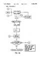
- FIG. 4is a flowchart illustrating a sequence of method steps for communicating voice and data signals between the base and handset of FIGS. 2 and 3;
- FIG. 5is a flowchart illustrating a sequence of method steps for answering an incoming telephone call according to the invention
- FIG. 6is a flowchart illustrating a sequence of method steps for predialing, storing and dialing a telephone number according to the invention
- FIG. 7is a flowchart illustrating a sequence of method steps for storing the predialed number of FIG. 6 in a general directory
- FIGS. 8a, 8b, and 8care flowcharts illustrating data save sequences for various telephone states according to the invention.
- FIG. 9is a flowchart illustrating a preferred name match sequence in a directory of received telephone calls.
- FIG. 1is a perspective view of a cordless portable telephone terminal 10 which, as will be described hereinbelow, is software configurable to provide enhanced telephone services in a voice and data communications network.
- the terminal 10includes a base station, hereinafter referred to as a base 11, which is mounted at an acute angle on a supporting platform 12. This position is conducive to supporting a cordless handset 13 in a corresponding cradle 14 of the base. It will be observed that the handset 13 is advantageously positioned to provide convenient access to its dialpad 15, other function buttons which will be subsequently described in greater detail, and to a display screen 16.
- the screen 16provides a liquid crystal display (LCD) having three lines with a capacity of ten alphanumeric characters per line.
- LCDliquid crystal display
- the base 11includes a dialpad 17 and certain ones of function keys that correspond to like keys on the handset 13.
- an electrical connection for battery chargingis established in a conventional manner by means of corresponding mating electrical contacts in the handset 13 and the cradle 14.
- Light emitting diodes (LEDs) on the base 11indicate the charging state of the battery as well as the functional state of two subscriber features.
- an illuminated LED 18 labelled MESSAGESindicates that a voice message awaits the subscriber at a local telephone company message service when the subscriber is a participant of such service.
- an illuminated LED 19 18indicates to the subscriber that a new caller has been added to a callers list, a feature to be subsequently described in greater detail.
- the base 11may function as a separate telephone terminal, with or without the handset 13, by operating in a conventional speaker phone mode in which a speaker, not shown, of the base 11 functions conventionally in reproducing voice signals.
- a microphone, not shown,functions conventionally for generating voice signals.
- the terminal 10constantly monitors the level of battery voltage in the handset 13 via an A/D microprocessor port. When a preset low level is detected, the terminal 10 indicates the low battery condition by a display message on the screen 16. The battery low display message appears for 5 seconds for every state change until the battery dies or the handset is returned to the base for charging.
- the terminal 10maximizes the stand-by time of the battery by reverting to a battery saver mode after 45 seconds in the idle state.
- the screen 16is powered off, the LEDs are shut down (except New Callers which flashes with a lower duty cycle) and the microprocessor goes to sleep.
- the microprocessorawakens for 100 ms every 400 ms to ensure not missing any user keypress or alerting arriving to the base 11.
- FIG. 2is a detailed block diagram of the base 11 and shows signal paths for both voice, control and data signals together with various components that achieve a functional cordless telephone terminal in accordance with the invention.
- the terminal 10is intended to provide all contemporary telephone subscriber services to a user, including call waiting, call forwarding, and voice mail which are examples of subscriber services not requiring a visual display. More significantly, caller identification services are available to the subscriber through the screen 16 on which directory numbers and caller names may be shown.
- the utility of the terminal 10is even further enhanced by the screen 16 coupled with stand alone features that are provided by the terminal 10.
- stand alone featuresinclude predialing a number which is shown on the screen 16 before dialing to ensure that the dialed number is correct.
- Any dialed number as well as any identifiable answered or unanswered caller stored in a callers list, that includes directory numbers and corresponding names,may also be dialed using a softkey which initiates a call with a single key depression.
- Two softkeysare provided which effect operations via user interactive prompts that appear above the keys on the display 16. Examples of such operations will be described in greater detail in the description to follow.
- the terminal 10establishes a wired connection with a local telephone central office (CO) by means of a line 30 that comprises a twisted pair of conductors connected to a tip and ring terminal 31.
- COlocal telephone central office
- Voice and data signals from the central officeare input to the terminal 31, the voice signals being analog in form and the data signals comprising packet switch data with calling line and customer name identification.
- the particular feature of calling number identificationrefers to a contemporary method and protocols of data transfers which are defined in Bellcore Technical References TR-TSY-00030 and TR-TSY-00031.
- Identification datais sent from the local telephone control office via frequency shift keying (FSK) from a Bell 202 modem per Bellcore TR-TSY-00030.
- FSKfrequency shift keying
- Such datacomprises a caller's name and number together with the current time and date.
- the transfer of encoded identification datais received between the first and second ringing signals on the line 30.
- Message Waiting datacan be transferred at any time that the terminal 10 is not active (i.e. on hook) and not necessarily between ring bursts.
- a custom local area signalling services (CLASS) message servicing modemreceives the FSK signals which are demodulated and output as class message servicing (CMS) data to an input 44 of a microprocessor 33 from which the data is retrievably stored in a nonvolatile NVRAM 34.
- CMSclass message servicing
- an output from a ring detector 35is coupled to a control port 36 to initiate a test to ascertain if the CMS data was corrupted during transmission.
- a bidirectional data bus 37couples CMS output data from the microprocessor 33 to a data input register 38 of a main microprocessor 39.
- the same output from the ring detector 35is coupled to a control port 43 of the microprocessor 39 wherein DTMF signals are generated and connected to a hybrid circuit 40. From this point the signals may be transmitted to the handset 13 or connected to the line 30.
- a ROM 45 in the microprocessor 39comprises firmware that controls the operation of both microprocessors 33 and 39 which run under software associated with this invention as described in greater detail hereinbelow.
- An EEPROM 47contains data, namely directory data, call log data and factory programming data as examples.
- a transmission data output 50is connected to a minimum shift keying (MSK) modem 51.
- MSKminimum shift keying
- a typical MSK modem 51is manufactured by Toshiba Corporation and is identified by part No. TC35470AF.
- the modemfunctions advantageously in either a full-duplex or half-duplex mode in a radio communications system for transmitting a control signal with sub-carrier frequency shift keying (FSK) modulation.
- FSKsub-carrier frequency shift keying
- a modulated output signal from the modem 51is coupled through a diode 52 to an input of a limited range frequency modulation (FM) transceiver 53 that includes a combined RF amplifier/oscillator module 54 having a controllable RF output in a frequency band of from 46 MHz to 49 MHz.
- the output from the module 54feeds a notch filter 55 having a split output path.
- One pathreturns to the input of the module 54 by way of a phase lock loop 56 to effect modulation of the RF carrier.
- Software overlaying digital information on the RF carrier waveis performed in the modem 51. Digital information is done through frequency shift keying. As described, the signal goes through the phase lock loop 56 where it locks onto the carrier. In this way encryption is carried out in the phase lock loop.
- the second output pathis coupled through a duplexer 57 to an antenna 58 from which a radio link is established with a corresponding antenna 59 in the handset 13.
- a hook switch 65When a call is received, and either the base 11 or its handset 13 goes offhook, a hook switch 65 is closed which completes a voice signal path from the terminal 31 to the primary winding of a line transformer 66.
- the output of the transformer 66is coupled to the circuit 40 from which an analog voice signal is fed through the amplifier 41 to drive the speaker 42.
- a second voice signal output from the circuit 40is coupled to a voice switch 67 and therefrom to an input of a voice amplifier 68 which is shown having a limiter 69 bridged thereacross for controlling wide signal swings through negative feedback.
- the output from the amplifier 68is connected to a compander 70 from which an output is taken through a potentiometer control 71 to the diode 52.
- the voice signalsare coupled through the diode 52 to the transceiver 53 for transmission to the handset 13 in a like manner to the transmitted data previously described.
- the modulated RF output signal from the base 11, bearing both voice and data signals,is received at the antenna 59 of the handset 13 and is connected to a duplexer 75 which directs the incoming signal to an RF amplifier 76 and therefrom to an input of an FM transceiver 77 which is functionally the same as the transceiver 53 of the base 11.
- the RF signal input to the transceiver 77is processed by an RF module 78 which comprises a first IF/second IF/mixer.
- the module 78is currently available as a commercial product from the Motorola Corporation and is identified under part No. MC 3362. It will be understood that the module 78 functions cooperatively with a phaselock loop module 79 which operates as a discriminator. The result is decryption of the encrypted data carried by the RF output signal from the base 11.
- An audio output from the module 78may include DTMF, voice and decrypted data signals, the latter consisting of logic ones and zeros corresponding to caller identification data associated With the CLASS service to which the telephone customer subscribes.
- Other decrypted dataincludes directory information and communication protocol; contents are handshaking protocol first, data being sent out and then a checksum byte going out.
- the audio outputis split into two paths, one being connected to a low pass filter 80 which passes voice signals and blocks the data signals.
- Voice signals output from the filter 80are coupled to a compander 81 where the dynamic range of the signals is restored and then output to a speaker driver amplifier 82 through an attenuation control 83.
- An output from the amplifier 82is connected to a speaker 84 of the handset where the voice signals are audibly reproduced.
- a manually operated volume control circuitis connected to circuit ground.
- the control circuitcomprises a single pole, three position switch 86 that permits selectively switching resistors 87 and 88 from the attenuator 83 to circuit ground or, in the case of the third position 89, to open the circuit ground connection.
- the value of the resistor 87 or 88 switched into the control circuitwill determine the signal input to the driver 82 with a consequent control of sound level at the speaker 84.
- the second audio output path from the module 78includes both voice signals and decrypted data transmitted from the transceiver 53 in the base 11.
- An MSK modem 95which corresponds exactly with the modem 51 in the base 11, restores the decrypted data input thereto and produces a pulse train of received data that is input to a microprocessor 96 which corresponds to the microprocessor 39 in the base 11.
- microprocessorsfunction in the same manner under like software control.
- the microprocessor 96such software is resident in ROM 94 which corresponds to ROM 45.
- ROM 94which corresponds to ROM 45.
- a comparison of the microprocessors 39 and 96shows the similarities of circuit structure which are functionally identical in both the base and handset. Therefore, to understand the functional aspects of the circuit blocks associated with both microprocessors, it will be sufficient to refer to the microprocessor 39 in FIG. 2 and the description related thereto for a complete understanding of the microprocessor 96.
- microprocessor 96Certain differences are apparent in the microprocessor 96, however, particularly in the formatting and output of the received digital data which is connected via the microprocessor 96 to the screen 16, shown in FIG. 3 as a liquid crystal display (LCD) module 98 which includes an LCD driver 99 and the LCD screen 16.
- LCDliquid crystal display
- a related LCD output from the microprocessor 96provides contrast control for the screen 16 by means of codes keyed in from the dialpad 15.
- a further differencemay be seen in a ring oscillator output from the microprocessor 96 which is applied to a ring amplifier 106 that drives an alerting transducer 107.
- a corresponding second output from the microprocessor 96is a ring volume control signal which is input to a ring volume control circuit 108 that is bridged across the input of the amplifier 106.
- Control of the modules 78, 79 and the modem 95is effected by means of a receive control output that effects control of these components through a controller 109.
- an out of range indicationis provided by the module 78.
- Thiscomprises an out of range signal that is coupled to an input of a noise cut module 110 which is connected across the output of the filter 80 to mute noisy voice signals.
- the out of range signalis also connected to an input of the microprocessor 96 which, on reception of the signal, effects a disconnect under software control.
- the resultis an output signal from the microprocessor 96 to the modem 95 which outputs a drive signal to the transceiver 77 that in turn transmits to the base 11 which is rendered on hook as illustrated in the flowcharts to follow.
- a microphone amplifier 116 and its limiter 117correspond to the amplifier 68 and limiter 69 of the base 11. Functionally they are the same but because of the aforenoted differences in the speech paths between the base and handset, the amplifier 116 input and the limiter 117 output are connected directly to the microphone 115. The amplifier 116 output and the input of the limiter 117 however, are connected to the compander 81 which corresponds to the compander 70 in the base 11.
- the voice switch 67, hybrid circuit 40, transformer 66 and hook switch 65cooperate under control of the microprocessor 39 to connect the received voice signals to the line 30.
- Other features associated with the terminal 10such as an intercom link between the handset and base as well as various features pertaining to dialing from both a dialpad and from memory and storing data into memory, will be understood by referring to the descriptions of such features together with corresponding flowcharts in the drawings.
- FIG. 4is a flowchart showing the various steps executed by the terminal 10 following receipt of an incoming call that is terminated at the modem 32.
- a test block 200determines if CLID packet data is present in accordance with Bellcore Technical References TR-TSY-00030 and TR-TSY-00031.
- a "No Information" message(block 201) is generated in the microprocessor 33 and is output therefrom along the bus 37 to the register 38 from which it is connected from the output 50 to modulate an RF carrier with subsequent transmission to the handset 13.
- packet datais present, it is terminated at the microprocessor 33 and subsequently tested for valid CLID data according to block 203.
- a second testis indicated at a decision block 204 to ascertain whether caller identification has been extracted. Should the result be negative, the "No Information" message is sent as previously described.
- caller identification datais stored in a non-volatile NVRAM 34 which communicates in a known manner with its associated microprocessor 33 over an address and data bus 48 as shown in block 205.
- a second bus 37communicates the microprocessor 33 with the data input register 38 of the main microprocessor 39 of the base 11 which is indicated by the block 206.
- Block 207indicates the step of utilizing the transmission data at the output 50 to modulate the modem 51, the output of which is coupled to the input of the transceiver 53, as previously described, for subsequent modulation of the RF carrier and transmission to the handset 13.
- Reception and demodulation of the RF carrieris indicated at block 208. It may be, however, that the handset 13 is out of range of the carrier from the base 11 which is determined in a decision block 209. In the event that the handset is out of range, as monitored by the module 110 (FIG. 3), an out of range signal is connected to the microprocessor 96 which responds with an out of range message retrieved from the EEPROM 97 and applied to the module 98 for display. Concurrently, a warning tone sounds. Both conditions are shown in the block 210. At this time the handset keypad 15 is inactive. If, within 30 seconds, the user improves the RF condition, the out of range condition is released and the terminal 10 returns to its pre-out of range state i.e., call is re-established or a feature session continues.
- Block 211shows that a timer is subsequently enabled and, as indicated in a decision block 212, if the poor RF condition persists for a time greater than 30 seconds, the handset 13 sends an END message to the base 11 and returns to an IDLE state i.e., the call is dropped or the feature session is exited provided the base 11 receives the END message.
- This sequenceinitiates in block 213 which sends the message to the base 11 followed by block 214 which indicates that the END message modulates the carrier which is then transmitted to the base 11.
- Block 215follows with the step of receiving the RF carrier which is demodulated in the base, followed by a decision block 216 which tests whether the base 11 received the END message. As indicated, an affirmative reply takes the handset 13 to idle as shown in block 217.
- the demodulated signal of the block 208is terminated at the microprocessor 96 as shown in block 218 which includes the step of formatting the CLID data for display on the module 98 in accordance with the block 219.
- the microprocessor 96generates a ring signal at the block 220 which is then applied as a ring alert in the handset 13 as shown in block 221.
- a decision block 222shows the result of an unanswered call, an END message being sent out from the block 213.
- a decision to answer the callleads to a series of method steps illustrated in the flowchart of FIG. 5.
- An affirmative decision in the block 222 of FIG. 4terminates at A which comprises the input for the flowchart of FIG. 5 wherein subsequent method steps are initiated.
- a dedicated TALK key 20is pressed by the user to enable the microprocessor 96 which responds under stored instructions in the EEPROM 97.
- a control instruction from the microprocessormodulates the RF carrier in the transceiver 77 which is transmitted to the base 11 as indicated in block 251.
- the carrieris received and demodulated at the base 11 in accordance with the block 252 and is subsequently terminated at the microprocessor 39 in the base according to the block 253.
- the microprocessor 39sets the hook switch 65 to an offhook condition as shown in block 254, thereby connecting the primary winding of the transformer 66 to the terminal 31 and consequently to the line 30.
- a control signal output from the microprocessor 39enables the audio output from the transceiver 77 and likewise enables the compander 81, the speaker amplifier driver 82 and the microphone amplifier 116 to render the handset 13 operational in accordance with blocks 255 and 256.
- FIG. 6is a flowchart illustrating two features of the invention embodied in the terminal 10. First is the capability of predialing a number on the keypad 15 of the handset and reviewing same on the screen 16 to ensure accuracy of the telephone number before actual dialing. A second feature is to save the number to a directory or a redial register. The method steps shown in FIG. 6 also illustrate the manner in which the number is dialed out from the terminal 10.
- An input block 275represents the step of predialing the number via the keypad 15.
- the dialpadis scanned by the microprocessor 96 whereby individual key depressions are stored in an input buffer thereof and are subsequently formatted in accordance with instructions stored in the EEPROM 97, such formatting comprising the sequential spacing apart of the telephone number to be displayed by the module 98 in a format to which telephone users are accustomed.
- a directory numbermay be entered from the keypad as a continuous flow of digits
- the formatting performed by the microprocessor 96introduces appropriate spaces between numbers. In conventional presentation form, each of the spaces between groups of numbers would be occupied by a dash or hyphen.
- the microprocessor 96Following the formatting indicated in the block 276, the microprocessor 96 generates an LCD control signal which is connected to the driver 99 and therefrom to the screen 16 in accordance with the block 277.
- the duration of timeoutis arbitrary but, as previously noted, is set at 45 seconds in the present embodiment.
- the displayis changed as indicated in the block 279. At this point in time the predialed number is lost and requires reentry from the dialpad.
- a counterstarts in accordance with block 280 and following an interval of 45 seconds the handset 13 is returned to idle and the screen 16 is blanked according to block 281.
- the timeout interval of block 285represents an interval during which a user may dial the number on display in block 277. This is indicated in the decision block 282 which shows that the number may be dialed either by striking a softkey associated with a DIAL user interactive prompt on the screen 16 or by striking the dedicated Talk key 20 in the keypad 15. In either event of dial initiation shown in blocks 283 and 284, a 45 second timeout procedure is initiated in block 285 as described hereinabove.
- a subsequent testis shown in a decision block 286 wherein it is determined if the handset 13 is out of range from the base 11. In the event that the handset is out of range, the same procedure is followed as that illustrated and described in FIG. 4.
- block 287indicates that the microprocessor 96 generates a transmission data output to the modem 95 for modulation and therefrom to the transceiver 77 for transmission to the base 11.
- the received carrieris demodulated in the base 11 as shown in block 288 and is subsequently terminated at the microprocessor 39 in accordance with block 289.
- the microprocessor 39responds by generating a DTMF signal in accordance with the block 290 so as to set the hook switch 65 to its offhook state in accordance with the block 291.
- the hybrid circuit 40is enabled as indicated in block 292 and couples the DTMF signals through the transformer 66 to the terminal 31 and thence to the line 30 for connection to the central office which is representative of the block 293.
- the microprocessor 39Concurrent with DTMF signal generation, the microprocessor 39 outputs the dialed number sequence over the data bus 37 to the microprocessor 33 according to block 294 where it is stored in a REDIAL register as indicated in block 95.
- Terminal B in FIG. 6is directed to a Save routine shown in FIG. 7.
- block 300indicates that the predialed number displayed on the screen 16 may be saved to a number directory by depressing a dedicated Save key on the handset 13. Thereafter the microprocessor 96 calls up a user interactive prompting message, ENTER NAME NOW, which is displayed on the screen 16 as indicated in block 301.
- the userdecides if the name is to be entered.
- An affirmative response from the usermeans that a name corresponding to the number may be entered via the keypad 15, block 303, following which the entered name is saved in a name field of the directory together with its corresponding number in a number field in accordance with block 304.
- the block 304represents saving the name in a single step, it will be understood that this is a simplification of the several steps shown in FIG. 6 which indicate the steps following reception of the predialed number at the microprocessor 39 and subsequent storage of the number in the redial register at the microprocessor 33. In the case of storing the corresponding name, storage occurs in the nonvolatile memory NVRAM 34 in which the directory resides.
- FIGS. 8a, b and care flowcharts illustrating various directory sequences for data storage which include Predial, Redial and Callers Item states. These flowcharts follow the description of the flowchart in FIG. 7 illustrating the required steps to save to the directory. Both names and numbers are stored in the directory. As described in FIG. 7, pressing the dedicated save key adds a new name and number to the directory wherein the names are listed alphabetically by the first word stored. By pressing dedicated scroll keys on the handset 13, the user can scroll through the items or use a dialpad search for a shortcut. The directory can be accessed using the handset 13 only.
- the hardware associated with the directorycomprises the microprocessor 96 in the handset 13 and microprocessors 33 and 39 in the base 11.
- incoming data from CLID packetsis received at the base and is transmitted to the handset where it is formatted by the microprocessor 96 and displayed on the screen 16.
- the aforenoted dedicated Save keyis depressed which initiates the procedure for saving the caller identification data to the nonvolatile NVRAM 34.
- the dialpad and dedicated keys of the handset 13thus allow a user to interact with the directory feature over the radio link between the base and handset.
- Informationmay be stored into the directory from a number of sources:
- the directory featureis accessed by pressing a dedicated directory key or a dedicated save key as described. Once in the directory, the various items stored can be viewed by scrolling up or down or to the left or right by the dedicated scroll keys.
- the maximum number of items in the directoryis 30, although, as previously expressed, this is not a limiting quantity and may vary depending on the size of the memory used.
- Directory itemsare entered by the user via the save sequence as described in FIG. 7, but since the directory is designed for both name and number items, stored in respective name and number fields, the user can choose to enter number only items.
- Number Only Itemshave a name field which contains the designation "No name”. However, the user can choose to ADD (FIG. 8c) a name at any time.
- both names and numberscan be edited by means of a position indicating cursor which locates an alphanumeric character, the dialpad 15 and a dedicated delete key on the handset 13.
- both names and numbersmay be edited using a softkey appearing under the user interactive prompt CHNGE on the screen 16, an example of which is shown in the block 279 of FIG. 6.
- a search shortcutis initiated.
- the shortcut featurepermits the user to quickly search the directory by matching the characters on the dialpad key to the characters in the name field of a directory item and then jumping to that item.
- a matching algorithmaccepts a dialpad key character, which may be a letter, special character or digit, and looks for a match with the first character of the name.
- Directory items that do have namesare sorted in alphabetical order according to the first character of the name string. Directory items having "No name" in the Name field are never searched from the dialpad.
- the followingis an example of the shortcut search when the handset is in a Directory Header or Directory Item state:
- the matching algorithmlooks for all Names which begin with the letter "K”. If more than one item "matches”, i.e., if more than one Name has a first character which matches the dialpad search character, the user will be shown the first match which occurs in accordance with the directory order.
- FIG. 9is a flowchart for preferred name matching through which identification of a caller is personalized.
- a match algorithmwill search the directory for matching numbers. If a match is discovered, the name from the directory is displayed and stored in the callers list. The directory item's name field will be displayed if no name is received or it will replace any name that is received. It will be understood that matching occurs on the last ten digits of the directory item or the last seven digits depending on how many digits are received from the CLID packet.
- a preferred name matchis performed in the following manner:
- dialable10 digits or more
- the user-entered directory item(name and number) is displayed during the incoming call and stored in the callers list if applicable.
Landscapes
- Engineering & Computer Science (AREA)
- Signal Processing (AREA)
- Computer Networks & Wireless Communication (AREA)
- Mobile Radio Communication Systems (AREA)
Abstract
Description
______________________________________ IF key event = Dialpad Go to Directory item state Go to first Name item which matches the first character on the Dialpad key IF no match is found Show "<Character> No item entered" REPEAT IF next key event = same Dialpad key Go to first Name item which matches the next character on the Dialpad key ELSE IF next key event = different Dialpad key Go to first Name item which matches the first character on the new Dialpad key IF no match is found Show "<Character> No Item entered" ______________________________________
Claims (19)
Priority Applications (3)
| Application Number | Priority Date | Filing Date | Title |
|---|---|---|---|
| US08/175,534US5581599A (en) | 1993-12-30 | 1993-12-30 | Cordless telephone terminal |
| CA002133859ACA2133859C (en) | 1993-12-30 | 1994-10-07 | Cordless telephone terminal |
| US08/758,887US5752195A (en) | 1993-12-30 | 1996-12-02 | Cordless telephone terminal |
Applications Claiming Priority (1)
| Application Number | Priority Date | Filing Date | Title |
|---|---|---|---|
| US08/175,534US5581599A (en) | 1993-12-30 | 1993-12-30 | Cordless telephone terminal |
Related Child Applications (1)
| Application Number | Title | Priority Date | Filing Date |
|---|---|---|---|
| US08/758,887ContinuationUS5752195A (en) | 1993-12-30 | 1996-12-02 | Cordless telephone terminal |
Publications (1)
| Publication Number | Publication Date |
|---|---|
| US5581599Atrue US5581599A (en) | 1996-12-03 |
Family
ID=22640608
Family Applications (2)
| Application Number | Title | Priority Date | Filing Date |
|---|---|---|---|
| US08/175,534Expired - LifetimeUS5581599A (en) | 1993-12-30 | 1993-12-30 | Cordless telephone terminal |
| US08/758,887Expired - LifetimeUS5752195A (en) | 1993-12-30 | 1996-12-02 | Cordless telephone terminal |
Family Applications After (1)
| Application Number | Title | Priority Date | Filing Date |
|---|---|---|---|
| US08/758,887Expired - LifetimeUS5752195A (en) | 1993-12-30 | 1996-12-02 | Cordless telephone terminal |
Country Status (2)
| Country | Link |
|---|---|
| US (2) | US5581599A (en) |
| CA (1) | CA2133859C (en) |
Cited By (46)
| Publication number | Priority date | Publication date | Assignee | Title |
|---|---|---|---|---|
| WO1997032425A1 (en)* | 1996-02-27 | 1997-09-04 | U-Tel, Inc. | Telecommunications system for accessing subscriber premises equipment using ring suppression |
| US5748709A (en)* | 1995-09-25 | 1998-05-05 | Sheerin; Howard H. | Programmable answering machine with multiple voice boxes and caller ID |
| US5752195A (en)* | 1993-12-30 | 1998-05-12 | Northern Telecom Limited | Cordless telephone terminal |
| US5787157A (en)* | 1995-06-20 | 1998-07-28 | Susan Garfin | Gateway device for telecommunication station |
| US5812649A (en)* | 1996-05-02 | 1998-09-22 | Aastra Aerospace Inc. | Method and apparatus for supporting spontaneous call waiting identification |
| US5841838A (en)* | 1994-11-17 | 1998-11-24 | Brother Kogyo Kabushiki Kaisha | Telephone answering unit with caller identification and message recording function |
| WO1998046034A3 (en)* | 1997-04-10 | 1999-01-07 | At & T Wireless Services Inc | Method and system for delivering a voice mail notification to a subscriber using cellular phone network |
| US5867774A (en)* | 1996-12-27 | 1999-02-02 | Motorola, Inc. | Smart remote control panel for a radio |
| US5872838A (en)* | 1997-05-29 | 1999-02-16 | Huang; Wen-Liang | Trim phone circuit device having a calling line identification |
| US5911119A (en)* | 1993-03-22 | 1999-06-08 | Phonex Corporation | Secure cordless telephone extension system and method |
| USD410647S (en) | 1998-01-23 | 1999-06-08 | Thomson Consumer Electronics, Inc. | Telephone handset |
| WO1999031857A1 (en)* | 1997-12-12 | 1999-06-24 | Thomson Consumer Electronics, Inc. | Multi-line telephone system for handling incoming caller id messages |
| US5937347A (en)* | 1996-11-06 | 1999-08-10 | Nortel Networks Corporation | Interactive subscriber telephone terminal with automatic management software download feature |
| US5999809A (en)* | 1994-11-18 | 1999-12-07 | Canon Kabushiki Kaisha | Wireless communication apparatus with distinct alarm signals |
| US6021336A (en)* | 1995-07-21 | 2000-02-01 | Sony Corporation | Portable communication terminal capable of transmitting text data |
| US6061560A (en)* | 1997-04-30 | 2000-05-09 | Nortel Networks Corporation | Method and apparatus for delivering and presenting calling name information in a wireless communications system |
| US6104909A (en)* | 1997-07-30 | 2000-08-15 | Motorola, Inc. | Method and apparatus for reporting status information in a fixed wireless terminal |
| US6148213A (en)* | 1995-07-05 | 2000-11-14 | Lucent Technologies Inc. | Method and apparatus for accessing a telephone answering device from a cordless telephone portable unit |
| US6148214A (en)* | 1997-06-17 | 2000-11-14 | U.S. Philips Corporation | Telephone using service messages for identification signals |
| US6188886B1 (en) | 1998-06-04 | 2001-02-13 | Nortel Networks Limited | Server based voice call offer while telephone in data session |
| US6219409B1 (en) | 1998-02-27 | 2001-04-17 | Sharegate, Inc. | Premises gateway and premises network interfaces for accessing subscriber premises equipment and communication networks using ring suppression |
| US6226368B1 (en)* | 1998-05-21 | 2001-05-01 | Advanced Micro Devices, Inc. | System and method for automatically updating a clock using caller ID information |
| US6226512B1 (en) | 1998-06-04 | 2001-05-01 | Nortel Networks Limited | Apparatus and method for displaying caller attributes |
| US6252942B1 (en)* | 1997-07-30 | 2001-06-26 | Harris Corporation | Wireless butt set |
| US6278773B1 (en)* | 1996-06-03 | 2001-08-21 | Webtv Networks, Inc. | Determining and disclosing the indentity of telephone caller |
| US6278886B1 (en)* | 1997-07-25 | 2001-08-21 | Samsung Electronics Co., Ltd. | Device and method for inputting and transmitting messages in a predetermined sequence in a portable telephone |
| US6317491B1 (en)* | 1998-04-27 | 2001-11-13 | Inventec Corporation | Method and apparatus for an intelligent telecommunication base unit and a detachable mobile information unit |
| US6345187B1 (en) | 1999-05-24 | 2002-02-05 | Agere Systems Guardian Corp. | Receipt of type II caller identification in multi-cordless environment |
| KR100333047B1 (en)* | 1999-06-18 | 2002-04-24 | 박종섭 | Method for controlling of originating number display in CDMA mobile communication system |
| US6405172B1 (en)* | 2000-09-09 | 2002-06-11 | Mailcode Inc. | Voice-enabled directory look-up based on recognized spoken initial characters |
| US6501968B1 (en)* | 1997-04-21 | 2002-12-31 | Canon Kabushiki Kaisha | Battery-powered communications apparatus |
| US20030012260A1 (en)* | 1998-06-30 | 2003-01-16 | Walley John S. | Direct conversion spread spectrum time division duplex radio |
| US20030036411A1 (en)* | 2001-08-03 | 2003-02-20 | Christian Kraft | Method of entering characters into a text string and a text-editing terminal using the method |
| EP1324575A1 (en)* | 2001-12-28 | 2003-07-02 | Sony International (Europe) GmbH | Generic call-numbers for calling line identification |
| US6597905B1 (en) | 1996-10-31 | 2003-07-22 | Nec Corporation | Cordless telephone system and method for transferring caller line identification information to wireless remote handsets |
| US20030158043A1 (en)* | 2001-12-21 | 2003-08-21 | Charloc Hammer | Use of indole-3-succinic acid as auxin |
| US6697482B1 (en)* | 1998-11-26 | 2004-02-24 | Alcatel | Method and system for transmitting messages to subscribers during the set-up stage of incoming telephone calls |
| US20040192276A1 (en)* | 1997-09-09 | 2004-09-30 | Wesby Philip Bernard | Emergency mobile radio telephone with reduced key set |
| US20050272475A1 (en)* | 2004-06-03 | 2005-12-08 | Lg Electronics Inc. | Idle mode indication system and method for mobile terminal |
| US20060122925A1 (en)* | 2002-05-21 | 2006-06-08 | Wesby Philip B | System and method for remote asset management |
| DE19849584B4 (en)* | 1997-10-27 | 2006-10-26 | Matsushita Electric Industrial Co., Ltd., Kadoma | Wireless telephone device |
| US20070041541A1 (en)* | 2005-08-19 | 2007-02-22 | Eimobile Inc. | Method for Automatic Information Capturing of Communication Events |
| US7583197B2 (en) | 2000-05-23 | 2009-09-01 | Eveline Wesby Van Swaay | Programmable communicator |
| US7805542B2 (en) | 1997-02-25 | 2010-09-28 | George W. Hindman | Mobile unit attached in a mobile environment that fully restricts access to data received via wireless signal to a separate computer in the mobile environment |
| US20160349823A1 (en)* | 2015-05-26 | 2016-12-01 | Lutron Electronics Co., Inc. | Temperature control device with automatically adjustable backlighting |
| US11337047B1 (en) | 2002-05-21 | 2022-05-17 | M2M Solutions Llc | System and method for remote asset management |
Families Citing this family (69)
| Publication number | Priority date | Publication date | Assignee | Title |
|---|---|---|---|---|
| JPH08293830A (en)* | 1995-04-20 | 1996-11-05 | Sony Corp | Portable telephone set and display adapter |
| JP3081524B2 (en)* | 1995-06-23 | 2000-08-28 | 三洋電機株式会社 | Communication equipment |
| GB2310567B (en)* | 1996-02-23 | 2000-04-26 | Nokia Mobile Phones Ltd | A radio telephone |
| US6996609B2 (en)* | 1996-05-01 | 2006-02-07 | G&H Nevada Tek | Method and apparatus for accessing a wide area network |
| SE520696C2 (en) | 1996-06-27 | 2003-08-12 | Ericsson Telefon Ab L M | Ways to generate text message with a calling party's phone number and name information and transfer it to a called mobile station |
| CA2188846A1 (en)* | 1996-10-25 | 1998-04-25 | Kris William Kramer | Call Management Services to Telephone Devices Which are Not Directly Connected to a Central Office |
| JP2907155B2 (en)* | 1996-10-31 | 1999-06-21 | 日本電気株式会社 | Telephone equipment |
| US5960066A (en) | 1996-11-07 | 1999-09-28 | Lucent Technologies, Inc. | Method and apparatus for using telephone house wiring for voice/data network |
| JP2912274B2 (en)* | 1996-12-20 | 1999-06-28 | 静岡日本電気株式会社 | Radio selective call receiver |
| US6408191B1 (en)* | 1996-12-31 | 2002-06-18 | Lucent Technologies Inc. | Arrangement for displaying message screens on a telephone terminal |
| US6690681B1 (en) | 1997-05-19 | 2004-02-10 | Airbiquity Inc. | In-band signaling for data communications over digital wireless telecommunications network |
| US6493338B1 (en) | 1997-05-19 | 2002-12-10 | Airbiquity Inc. | Multichannel in-band signaling for data communications over digital wireless telecommunications networks |
| JP2943765B2 (en)* | 1997-06-06 | 1999-08-30 | 日本電気株式会社 | Mobile communication terminal |
| US6522265B1 (en)* | 1997-06-25 | 2003-02-18 | Navox Corporation | Vehicle tracking and security system incorporating simultaneous voice and data communication |
| US6140956A (en) | 1997-06-25 | 2000-10-31 | Cellutrac, Inc. | Vehicle tracking and security system incorporating simultaneous voice and data communication |
| GB2327569A (en)* | 1997-07-18 | 1999-01-27 | Northern Telecom Ltd | Central office switch services for fixed wireless access communication systems |
| US6711402B1 (en)* | 1997-08-06 | 2004-03-23 | Nortel Networks Ltd. | Method and apparatus for displaying calling party information |
| US6061435A (en)* | 1997-10-03 | 2000-05-09 | Lucent Technologies Inc. | Cordless telephone system having a handset with non-telephone functionality |
| US6049713A (en)* | 1997-10-08 | 2000-04-11 | Telefonaktiebolaget Lm Ericsson (Publ) | System and method of providing calling-line identification (CLI) information to a mobile terminal in a radio telecommunications network |
| JPH11177675A (en)* | 1997-12-15 | 1999-07-02 | Sony Corp | Telephone terminal and caller number utilizing method |
| US6073031A (en)* | 1997-12-24 | 2000-06-06 | Nortel Networks Corporation | Desktop docking station for use with a wireless telephone handset |
| US6094156A (en)* | 1998-04-24 | 2000-07-25 | Henty; David L. | Handheld remote control system with keyboard |
| US6278887B1 (en)* | 1999-02-05 | 2001-08-21 | Neopoint, Inc. | System and method for power conservation in a wireless communication handset |
| US6321080B1 (en)* | 1999-03-15 | 2001-11-20 | Lucent Technologies, Inc. | Conference telephone utilizing base and handset transducers |
| US6385469B1 (en)* | 1999-06-22 | 2002-05-07 | Ericsson Inc. | System and method for providing battery gapping for mobile stations |
| US6711257B1 (en)* | 1999-07-27 | 2004-03-23 | Cisco Technology, Inc. | Telephone indicator system and method |
| US20060121938A1 (en)* | 1999-08-12 | 2006-06-08 | Hawkins Jeffrey C | Integrated handheld computing and telephony device |
| US6278742B1 (en)* | 1999-11-19 | 2001-08-21 | Siemens Information And Communication Mobile Llc. | Method and system for power-conserving interference avoidance in communication between a mobile unit and a base unit in a wireless telecommunication system |
| EP1102507A3 (en)* | 1999-11-19 | 2002-10-09 | Siemens Information and Communication Mobile LLC | Method and system for transmitting caller id information from a base station to a mobile unit outside the context of an incoming call |
| EP1102508A3 (en)* | 1999-11-19 | 2003-01-08 | Siemens Information and Communication Mobile LLC | Method and system for transmitting and receiving caller ID data in a wireless telephone system |
| US7231207B1 (en) | 1999-12-20 | 2007-06-12 | Agere Systems Inc. | Intelligent incoming call management during cordless intercom mode |
| CA2331234C (en)* | 2000-02-23 | 2008-03-18 | Lucent Technologies Inc. | Intelligent incoming call management during cordless intercom mode |
| JP4663949B2 (en)* | 2000-02-28 | 2011-04-06 | トムソン ライセンシング | Analog cordless telephone |
| KR20030070031A (en)* | 2000-11-16 | 2003-08-27 | 에트링크스 유에스에이, 인크. | Methods and apparatus for simultaneously communicating voice and data in an analog cordless telephone system |
| JP2002199455A (en)* | 2000-12-27 | 2002-07-12 | Matsushita Electric Ind Co Ltd | Cordless telephone equipment |
| GB0107642D0 (en)* | 2001-03-27 | 2001-05-16 | Nokia Mobile Phones Ltd | Communication terminal handling user-to-user information received during a call |
| KR200240690Y1 (en)* | 2001-05-07 | 2001-10-12 | 최병득 | A telephone combined with the picture frame |
| US6787776B2 (en)* | 2001-08-16 | 2004-09-07 | The Board Of Trustees Of Leland Stanford Junior University | Gas sensor for ammonia, carbon dioxide and water |
| JP2003070069A (en)* | 2001-08-29 | 2003-03-07 | Matsushita Electric Ind Co Ltd | Cordless telephone equipment |
| USD477583S1 (en) | 2001-09-14 | 2003-07-22 | Siemens Information& Communication Mobile Llc | Cordless telephone handset |
| USD477582S1 (en) | 2001-09-14 | 2003-07-22 | Siemens Information & Communication Mobile Llc | Cordless telephone handset |
| US7215965B2 (en) | 2001-11-01 | 2007-05-08 | Airbiquity Inc. | Facility and method for wireless transmission of location data in a voice channel of a digital wireless telecommunications network |
| JP3820968B2 (en)* | 2001-11-20 | 2006-09-13 | ブラザー工業株式会社 | Answering machine |
| US6909910B2 (en)* | 2002-02-01 | 2005-06-21 | Microsoft Corporation | Method and system for managing changes to a contact database |
| JP2004005006A (en)* | 2002-03-27 | 2004-01-08 | Nec Corp | Dictionary adding method of mobile communication terminal device |
| JP2003333173A (en)* | 2002-05-15 | 2003-11-21 | Brother Ind Ltd | Cordless telephone system, telephone of cordless telephone system, and terminal device of cordless telephone system |
| US20040081299A1 (en)* | 2002-10-24 | 2004-04-29 | Sbc Properties, L.P. | System and method for select messaging |
| US7236578B2 (en)* | 2003-01-08 | 2007-06-26 | Vtech Telecommunications Limited | System and method for remotely accessing caller ID information |
| US7295852B1 (en) | 2003-05-01 | 2007-11-13 | Palm, Inc. | Automated telephone conferencing method and system |
| US20060099975A1 (en)* | 2004-10-28 | 2006-05-11 | Sarosh Vesuna | Personal data assistant having a detachable voice communication device |
| US7508810B2 (en) | 2005-01-31 | 2009-03-24 | Airbiquity Inc. | Voice channel control of wireless packet data communications |
| US8675849B2 (en)* | 2005-02-09 | 2014-03-18 | Cisco Technology, Inc. | Ubiquitous transfer of a phone number to another phone |
| US20060217065A1 (en)* | 2005-03-23 | 2006-09-28 | Skipjam Corp. | Radio frequency remote control apparatus and methodology |
| US8014942B2 (en)* | 2005-06-15 | 2011-09-06 | Airbiquity, Inc. | Remote destination programming for vehicle navigation |
| US7689233B2 (en)* | 2005-12-30 | 2010-03-30 | Vtech Telecommunications Limited | Remote switching for handset handsfree speakerphone |
| US20070243898A1 (en)* | 2005-12-30 | 2007-10-18 | Alan Eyre | Multi-handset cordless voice over IP telephony system |
| US7924934B2 (en) | 2006-04-07 | 2011-04-12 | Airbiquity, Inc. | Time diversity voice channel data communications |
| US20080166990A1 (en)* | 2007-01-09 | 2008-07-10 | Shrage Toiv | Telephone Directory Assistance System |
| WO2008116999A1 (en) | 2007-03-16 | 2008-10-02 | Thomson Licensing | Call interception at a base station |
| US20090080624A1 (en)* | 2007-09-21 | 2009-03-26 | At&T Knowledge Ventures, Lp | System and Method for Rules-Based Caller ID Notification |
| MX2010003700A (en) | 2007-10-20 | 2010-04-21 | Airbiquity Inc | Wireless in-band signaling with in-vehicle systems. |
| US8594138B2 (en) | 2008-09-15 | 2013-11-26 | Airbiquity Inc. | Methods for in-band signaling through enhanced variable-rate codecs |
| US7983310B2 (en)* | 2008-09-15 | 2011-07-19 | Airbiquity Inc. | Methods for in-band signaling through enhanced variable-rate codecs |
| US8073440B2 (en) | 2009-04-27 | 2011-12-06 | Airbiquity, Inc. | Automatic gain control in a personal navigation device |
| US8418039B2 (en) | 2009-08-03 | 2013-04-09 | Airbiquity Inc. | Efficient error correction scheme for data transmission in a wireless in-band signaling system |
| JP2012199599A (en)* | 2009-08-06 | 2012-10-18 | Panasonic Corp | Cordless phone |
| US8249865B2 (en) | 2009-11-23 | 2012-08-21 | Airbiquity Inc. | Adaptive data transmission for a digital in-band modem operating over a voice channel |
| CA2805273A1 (en)* | 2010-07-16 | 2012-01-19 | Research In Motion Limited | Mobile wireless communications device with search shortcut and related methods |
| US8848825B2 (en) | 2011-09-22 | 2014-09-30 | Airbiquity Inc. | Echo cancellation in wireless inband signaling modem |
Citations (8)
| Publication number | Priority date | Publication date | Assignee | Title |
|---|---|---|---|---|
| JPS6223266A (en)* | 1985-07-23 | 1987-01-31 | Hitachi Ltd | Cellular system radiotelephony set |
| US5063588A (en)* | 1988-11-21 | 1991-11-05 | Motorola, Inc. | Communication system providing automatic identification of calling parties |
| US5077832A (en)* | 1989-08-07 | 1991-12-31 | Ericsson Ge Mobile Communications Inc. | Radio transceiver with optional display |
| US5121423A (en)* | 1989-07-13 | 1992-06-09 | Sharp Kabushiki Kaisha | Communication unit comprising caller identification function and caller identifying method in a digital communication network |
| US5285493A (en)* | 1989-01-19 | 1994-02-08 | Kabushiki Kaisha Toshiba | Radio tele-communication device with received message displaying feature |
| US5297203A (en)* | 1991-05-29 | 1994-03-22 | Video Technology Engineering, Ltd. | Digital cordless telephone apparatus |
| US5371788A (en)* | 1993-04-13 | 1994-12-06 | At&T Corp. | Arrangement for displaying menu screens on a telephone terminal |
| US5425077A (en)* | 1993-07-08 | 1995-06-13 | U.S. West Advanced Technologies, Inc. | Mobile telephone user interface including fixed and dynamic function keys and method of using same |
Family Cites Families (1)
| Publication number | Priority date | Publication date | Assignee | Title |
|---|---|---|---|---|
| US5581599A (en)* | 1993-12-30 | 1996-12-03 | Northern Telecom Limited | Cordless telephone terminal |
- 1993
- 1993-12-30USUS08/175,534patent/US5581599A/ennot_activeExpired - Lifetime
- 1994
- 1994-10-07CACA002133859Apatent/CA2133859C/ennot_activeExpired - Lifetime
- 1996
- 1996-12-02USUS08/758,887patent/US5752195A/ennot_activeExpired - Lifetime
Patent Citations (8)
| Publication number | Priority date | Publication date | Assignee | Title |
|---|---|---|---|---|
| JPS6223266A (en)* | 1985-07-23 | 1987-01-31 | Hitachi Ltd | Cellular system radiotelephony set |
| US5063588A (en)* | 1988-11-21 | 1991-11-05 | Motorola, Inc. | Communication system providing automatic identification of calling parties |
| US5285493A (en)* | 1989-01-19 | 1994-02-08 | Kabushiki Kaisha Toshiba | Radio tele-communication device with received message displaying feature |
| US5121423A (en)* | 1989-07-13 | 1992-06-09 | Sharp Kabushiki Kaisha | Communication unit comprising caller identification function and caller identifying method in a digital communication network |
| US5077832A (en)* | 1989-08-07 | 1991-12-31 | Ericsson Ge Mobile Communications Inc. | Radio transceiver with optional display |
| US5297203A (en)* | 1991-05-29 | 1994-03-22 | Video Technology Engineering, Ltd. | Digital cordless telephone apparatus |
| US5371788A (en)* | 1993-04-13 | 1994-12-06 | At&T Corp. | Arrangement for displaying menu screens on a telephone terminal |
| US5425077A (en)* | 1993-07-08 | 1995-06-13 | U.S. West Advanced Technologies, Inc. | Mobile telephone user interface including fixed and dynamic function keys and method of using same |
Cited By (92)
| Publication number | Priority date | Publication date | Assignee | Title |
|---|---|---|---|---|
| US5911119A (en)* | 1993-03-22 | 1999-06-08 | Phonex Corporation | Secure cordless telephone extension system and method |
| US5752195A (en)* | 1993-12-30 | 1998-05-12 | Northern Telecom Limited | Cordless telephone terminal |
| US5841838A (en)* | 1994-11-17 | 1998-11-24 | Brother Kogyo Kabushiki Kaisha | Telephone answering unit with caller identification and message recording function |
| US5999809A (en)* | 1994-11-18 | 1999-12-07 | Canon Kabushiki Kaisha | Wireless communication apparatus with distinct alarm signals |
| US5787157A (en)* | 1995-06-20 | 1998-07-28 | Susan Garfin | Gateway device for telecommunication station |
| US6148213A (en)* | 1995-07-05 | 2000-11-14 | Lucent Technologies Inc. | Method and apparatus for accessing a telephone answering device from a cordless telephone portable unit |
| US6021336A (en)* | 1995-07-21 | 2000-02-01 | Sony Corporation | Portable communication terminal capable of transmitting text data |
| US5748709A (en)* | 1995-09-25 | 1998-05-05 | Sheerin; Howard H. | Programmable answering machine with multiple voice boxes and caller ID |
| US5737400A (en)* | 1996-02-27 | 1998-04-07 | U-Tel Incorporated | Telecommunications system for accessing subscriber premises equipment using ring suppression |
| WO1997032425A1 (en)* | 1996-02-27 | 1997-09-04 | U-Tel, Inc. | Telecommunications system for accessing subscriber premises equipment using ring suppression |
| US5812649A (en)* | 1996-05-02 | 1998-09-22 | Aastra Aerospace Inc. | Method and apparatus for supporting spontaneous call waiting identification |
| US6278773B1 (en)* | 1996-06-03 | 2001-08-21 | Webtv Networks, Inc. | Determining and disclosing the indentity of telephone caller |
| US6597905B1 (en) | 1996-10-31 | 2003-07-22 | Nec Corporation | Cordless telephone system and method for transferring caller line identification information to wireless remote handsets |
| US5937347A (en)* | 1996-11-06 | 1999-08-10 | Nortel Networks Corporation | Interactive subscriber telephone terminal with automatic management software download feature |
| US6157708A (en)* | 1996-11-06 | 2000-12-05 | Nortel Networks Limited | Interactive subscriber telephone terminal with automatic management software download feature |
| US5867774A (en)* | 1996-12-27 | 1999-02-02 | Motorola, Inc. | Smart remote control panel for a radio |
| US7805542B2 (en) | 1997-02-25 | 2010-09-28 | George W. Hindman | Mobile unit attached in a mobile environment that fully restricts access to data received via wireless signal to a separate computer in the mobile environment |
| US20060234683A1 (en)* | 1997-04-10 | 2006-10-19 | Cingular Wireless Ii, Llc | Method and system for delivering a voice mail notification to a subscriber using cellular phone network |
| US7548745B2 (en) | 1997-04-10 | 2009-06-16 | At&T Mobility Ii Llc | Method and system for delivering a voice mail notification to a subscriber using cellular phone network |
| US6418307B1 (en) | 1997-04-10 | 2002-07-09 | At&T Wireless Services, Inc. | Method and system for delivering a voice mail notification to a subscriber using cellular phone network |
| US20020160756A1 (en)* | 1997-04-10 | 2002-10-31 | At&T Wireless Services, Inc. | Method and system for delivering a voice mail notification to a subscriber using cellular phone network |
| US6006087A (en)* | 1997-04-10 | 1999-12-21 | At&T Wireless Services, Inc. | Method and system for delivering a voice mail notification to a subscriber using cellular phone network |
| US7062257B2 (en) | 1997-04-10 | 2006-06-13 | Amin Umesh J | Method and system for delivering a voice mail notification to a subscriber using cellular phone network |
| US8634811B2 (en) | 1997-04-10 | 2014-01-21 | At&T Mobility Ii Llc | Method and system for delivering a voice mail notification to a subscriber using cellular phone network |
| US8320888B2 (en) | 1997-04-10 | 2012-11-27 | At&T Mobility Ii Llc | Method and system for delivering a voice mail notification to a subscriber using cellular phone network |
| US20090233580A1 (en)* | 1997-04-10 | 2009-09-17 | Amin Umesh J | Method and system for delivering a voice mail notification to a subscriber using cellular phone network |
| WO1998046034A3 (en)* | 1997-04-10 | 1999-01-07 | At & T Wireless Services Inc | Method and system for delivering a voice mail notification to a subscriber using cellular phone network |
| US6501968B1 (en)* | 1997-04-21 | 2002-12-31 | Canon Kabushiki Kaisha | Battery-powered communications apparatus |
| US6061560A (en)* | 1997-04-30 | 2000-05-09 | Nortel Networks Corporation | Method and apparatus for delivering and presenting calling name information in a wireless communications system |
| US5872838A (en)* | 1997-05-29 | 1999-02-16 | Huang; Wen-Liang | Trim phone circuit device having a calling line identification |
| US6148214A (en)* | 1997-06-17 | 2000-11-14 | U.S. Philips Corporation | Telephone using service messages for identification signals |
| US6278886B1 (en)* | 1997-07-25 | 2001-08-21 | Samsung Electronics Co., Ltd. | Device and method for inputting and transmitting messages in a predetermined sequence in a portable telephone |
| US6252942B1 (en)* | 1997-07-30 | 2001-06-26 | Harris Corporation | Wireless butt set |
| US6104909A (en)* | 1997-07-30 | 2000-08-15 | Motorola, Inc. | Method and apparatus for reporting status information in a fixed wireless terminal |
| US20060281420A1 (en)* | 1997-09-09 | 2006-12-14 | Wesby Philip B | Emergency Mobile Radio Telephone with Reduced Key Set |
| US20080004069A1 (en)* | 1997-09-09 | 2008-01-03 | Eveline Wesby Van Swaay | Mobile Phone with Programmed Keypad |
| US20040192276A1 (en)* | 1997-09-09 | 2004-09-30 | Wesby Philip Bernard | Emergency mobile radio telephone with reduced key set |
| DE19849584B4 (en)* | 1997-10-27 | 2006-10-26 | Matsushita Electric Industrial Co., Ltd., Kadoma | Wireless telephone device |
| WO1999031857A1 (en)* | 1997-12-12 | 1999-06-24 | Thomson Consumer Electronics, Inc. | Multi-line telephone system for handling incoming caller id messages |
| USD410647S (en) | 1998-01-23 | 1999-06-08 | Thomson Consumer Electronics, Inc. | Telephone handset |
| US6219409B1 (en) | 1998-02-27 | 2001-04-17 | Sharegate, Inc. | Premises gateway and premises network interfaces for accessing subscriber premises equipment and communication networks using ring suppression |
| US6317491B1 (en)* | 1998-04-27 | 2001-11-13 | Inventec Corporation | Method and apparatus for an intelligent telecommunication base unit and a detachable mobile information unit |
| US6226368B1 (en)* | 1998-05-21 | 2001-05-01 | Advanced Micro Devices, Inc. | System and method for automatically updating a clock using caller ID information |
| US6226512B1 (en) | 1998-06-04 | 2001-05-01 | Nortel Networks Limited | Apparatus and method for displaying caller attributes |
| US6188886B1 (en) | 1998-06-04 | 2001-02-13 | Nortel Networks Limited | Server based voice call offer while telephone in data session |
| US6862313B2 (en)* | 1998-06-30 | 2005-03-01 | Skyworks Solutions Inc. | Direct conversion spread spectrum time division duplex radio |
| US20030012260A1 (en)* | 1998-06-30 | 2003-01-16 | Walley John S. | Direct conversion spread spectrum time division duplex radio |
| US6697482B1 (en)* | 1998-11-26 | 2004-02-24 | Alcatel | Method and system for transmitting messages to subscribers during the set-up stage of incoming telephone calls |
| US6345187B1 (en) | 1999-05-24 | 2002-02-05 | Agere Systems Guardian Corp. | Receipt of type II caller identification in multi-cordless environment |
| KR100333047B1 (en)* | 1999-06-18 | 2002-04-24 | 박종섭 | Method for controlling of originating number display in CDMA mobile communication system |
| US9078152B2 (en) | 2000-05-23 | 2015-07-07 | M2M Solutions Llc | Programmable communicator |
| US8866589B2 (en) | 2000-05-23 | 2014-10-21 | M2M Solutions Llc | Programmable communicator |
| US9125079B2 (en) | 2000-05-23 | 2015-09-01 | M2M Solutions Llc | Programmable communicator |
| US8094010B2 (en) | 2000-05-23 | 2012-01-10 | Wesby-Van Swaay Eveline | Programmable communicator |
| US8872624B2 (en) | 2000-05-23 | 2014-10-28 | M2M Solutions Llc | Programmable communicator |
| US7583197B2 (en) | 2000-05-23 | 2009-09-01 | Eveline Wesby Van Swaay | Programmable communicator |
| US8633802B2 (en) | 2000-05-23 | 2014-01-21 | M2M Solutions Llc | Programmable communicator |
| US8542111B2 (en) | 2000-05-23 | 2013-09-24 | M2M Solutions Llc | Programmable communicator |
| US20100035580A1 (en)* | 2000-05-23 | 2010-02-11 | Wesby-Van Swaay Eveline | Programmable Communicator |
| US8648717B2 (en) | 2000-05-23 | 2014-02-11 | M2M Solutions Llc | Programmable communicator |
| US6405172B1 (en)* | 2000-09-09 | 2002-06-11 | Mailcode Inc. | Voice-enabled directory look-up based on recognized spoken initial characters |
| US20030036411A1 (en)* | 2001-08-03 | 2003-02-20 | Christian Kraft | Method of entering characters into a text string and a text-editing terminal using the method |
| US20030158043A1 (en)* | 2001-12-21 | 2003-08-21 | Charloc Hammer | Use of indole-3-succinic acid as auxin |
| EP1324575A1 (en)* | 2001-12-28 | 2003-07-02 | Sony International (Europe) GmbH | Generic call-numbers for calling line identification |
| US20030152205A1 (en)* | 2001-12-28 | 2003-08-14 | Gregor Winkler | Generic call-numbers for calling line identification |
| US20060122925A1 (en)* | 2002-05-21 | 2006-06-08 | Wesby Philip B | System and method for remote asset management |
| US10278041B2 (en) | 2002-05-21 | 2019-04-30 | M2M Solutions Llc | System and method for remote asset management |
| US8457622B2 (en) | 2002-05-21 | 2013-06-04 | M2M Solutions Llc | System and method for remote asset management |
| US8577358B2 (en) | 2002-05-21 | 2013-11-05 | M2M Solutions Llc | System and method for remote asset management |
| US8577359B2 (en) | 2002-05-21 | 2013-11-05 | M2M Solutions Llc | System and method for remote asset management |
| US11337047B1 (en) | 2002-05-21 | 2022-05-17 | M2M Solutions Llc | System and method for remote asset management |
| US8180336B2 (en) | 2002-05-21 | 2012-05-15 | M2M Solutions Llc | System and method for remote asset management |
| US10791442B2 (en) | 2002-05-21 | 2020-09-29 | M2M Solutions Llc | System and method for remote asset management |
| US8504007B2 (en) | 2002-05-21 | 2013-08-06 | M2M Solutions Llc | System and method for remote asset management |
| US20090247146A1 (en)* | 2002-05-21 | 2009-10-01 | Philip Bernard Wesby | System and Method for Remote Asset Management |
| US7558564B2 (en) | 2002-05-21 | 2009-07-07 | Philip Bernard Wesby | System and method for remote asset management |
| US8880054B2 (en) | 2002-05-21 | 2014-11-04 | M2M Solutions Llc | System and method for remote asset management |
| US10038989B1 (en) | 2002-05-21 | 2018-07-31 | M2M Solutions Llc | System and method for remote asset management |
| US9118701B2 (en) | 2002-05-21 | 2015-08-25 | M2M Solutions Llc | System and method for remote asset management |
| US9961477B2 (en) | 2002-05-21 | 2018-05-01 | M2M Solutions Llc | System and method for remote asset management |
| US20050272475A1 (en)* | 2004-06-03 | 2005-12-08 | Lg Electronics Inc. | Idle mode indication system and method for mobile terminal |
| US20070041541A1 (en)* | 2005-08-19 | 2007-02-22 | Eimobile Inc. | Method for Automatic Information Capturing of Communication Events |
| US7894583B2 (en)* | 2005-08-19 | 2011-02-22 | Elmobile Inc. | Method for automatic information capturing of communication events |
| US20110142219A1 (en)* | 2005-08-19 | 2011-06-16 | Huoy-Yu Liou | Method for Automatic Information Capturing of Communication Events |
| US8600023B2 (en)* | 2005-08-19 | 2013-12-03 | Elmobile Inc. | Method for automatic information capturing of communication events |
| US20160349823A1 (en)* | 2015-05-26 | 2016-12-01 | Lutron Electronics Co., Inc. | Temperature control device with automatically adjustable backlighting |
| US10133337B2 (en)* | 2015-05-26 | 2018-11-20 | Lutron Electronics Co., Inc. | Temperature control device with automatically adjustable backlighting |
| US10416749B2 (en) | 2015-05-26 | 2019-09-17 | Lutron Technology Company Llc | Temperature control device with automatically adjustable backlighting |
| US10824218B2 (en) | 2015-05-26 | 2020-11-03 | Lutron Technology Company Llc | Temperature control device with automatically adjustable backlighting |
| US11422610B2 (en) | 2015-05-26 | 2022-08-23 | Lutron Technology Company Llc | Temperature control device with automatically adjustable backlighting |
| US11907038B2 (en) | 2015-05-26 | 2024-02-20 | Lutron Technology Company Llc | Temperature control device with automatically adjustable backlighting |
| US12326771B2 (en) | 2015-05-26 | 2025-06-10 | Lutron Technology Company Llc | Temperature control device with automatically adjustable backlighting |
Also Published As
| Publication number | Publication date |
|---|---|
| CA2133859A1 (en) | 1995-07-01 |
| US5752195A (en) | 1998-05-12 |
| CA2133859C (en) | 1999-12-14 |
Similar Documents
| Publication | Publication Date | Title |
|---|---|---|
| US5581599A (en) | Cordless telephone terminal | |
| US5349638A (en) | Universal calling/originating number identification | |
| US7254223B1 (en) | Method and apparatus for improved personal communication devices and systems | |
| US7286658B1 (en) | Method and apparatus for improved personal communication devices and systems | |
| CA2192414C (en) | Method and apparatus for operating a communication device | |
| US5526403A (en) | Wireline interface for cellular telephone | |
| US4524244A (en) | Digital and voice telecommunication apparatus | |
| US6038443A (en) | Calling party announcement apparatus | |
| US5581593A (en) | Combination telephone and alphanumeric entry device | |
| KR100308348B1 (en) | Ring count controlled by incoming call related information | |
| US20070121860A1 (en) | Method and apparatus for indicating a caller's intent | |
| US7142846B1 (en) | Method and apparatus for improved paging receiver and system | |
| EP0999691A1 (en) | Ring type based on call related information | |
| JPH06318976A (en) | Telecommunication network | |
| JPH10276257A (en) | Telephone system | |
| JP3459674B2 (en) | Cordless telephone terminal and its operation method | |
| JP2004120788A (en) | Mobile phone equipment | |
| KR960003104B1 (en) | Wireless calling devices for keyphone system | |
| KR0162615B1 (en) | Specifying inner line to read given-up call data in key-phone system | |
| KR19980035372A (en) | Communication terminal with automatic continuous redial | |
| JPH07303282A (en) | Simple type portable telephone set | |
| JPH07303138A (en) | Simplified portable telephone | |
| JPH07131517A (en) | Answering machine | |
| JPH07203008A (en) | Answering machine | |
| JPH07303281A (en) | Simple type portable telephone set |
Legal Events
| Date | Code | Title | Description |
|---|---|---|---|
| AS | Assignment | Owner name:NORTHERN TELECOM LIMITED, CANADA Free format text:ASSIGNMENT OF ASSIGNORS INTEREST;ASSIGNOR:SPARKSMAN, STEVEN W.;REEL/FRAME:007605/0726 Effective date:19950104 | |
| AS | Assignment | Owner name:NORTHERN TELECOM LIMITED, CANADA Free format text:ASSIGNMENT OF ASSIGNORS INTEREST;ASSIGNOR:BELL-NORTHERN RESEARCH LTD.;REEL/FRAME:007572/0798 Effective date:19941207 Owner name:BELL-NORTHERN RESEARCH LTD., CANADA Free format text:ASSIGNMENT OF ASSIGNORS INTEREST;ASSIGNORS:TSUJI, BRUCE H.;MCGARRY, SUSAN J.;REEL/FRAME:007572/0806 Effective date:19941121 | |
| STCF | Information on status: patent grant | Free format text:PATENTED CASE | |
| CC | Certificate of correction | ||
| FEPP | Fee payment procedure | Free format text:PAYOR NUMBER ASSIGNED (ORIGINAL EVENT CODE: ASPN); ENTITY STATUS OF PATENT OWNER: LARGE ENTITY | |
| AS | Assignment | Owner name:NORTEL NETWORKS CORPORATION, CANADA Free format text:CHANGE OF NAME;ASSIGNOR:NORTHERN TELECOM LIMITED;REEL/FRAME:010567/0001 Effective date:19990429 | |
| FPAY | Fee payment | Year of fee payment:4 | |
| AS | Assignment | Owner name:NORTEL NETWORKS LIMITED, CANADA Free format text:CHANGE OF NAME;ASSIGNOR:NORTEL NETWORKS CORPORATION;REEL/FRAME:011195/0706 Effective date:20000830 Owner name:NORTEL NETWORKS LIMITED,CANADA Free format text:CHANGE OF NAME;ASSIGNOR:NORTEL NETWORKS CORPORATION;REEL/FRAME:011195/0706 Effective date:20000830 | |
| FPAY | Fee payment | Year of fee payment:8 | |
| FPAY | Fee payment | Year of fee payment:12 | |
| AS | Assignment | Owner name:ROCKSTAR BIDCO, LP, NEW YORK Free format text:ASSIGNMENT OF ASSIGNORS INTEREST;ASSIGNOR:NORTEL NETWORKS LIMITED;REEL/FRAME:027164/0356 Effective date:20110729 | |
| AS | Assignment | Owner name:ROCKSTAR CONSORTIUM US LP, TEXAS Free format text:ASSIGNMENT OF ASSIGNORS INTEREST;ASSIGNOR:ROCKSTAR BIDCO, LP;REEL/FRAME:030094/0370 Effective date:20120509 | |
| AS | Assignment | Owner name:SPHERIX INCORPORATED, VIRGINIA Free format text:ASSIGNMENT OF ASSIGNORS INTEREST;ASSIGNOR:ROCKSTAR CONSORTIUM US LP;REEL/FRAME:031113/0886 Effective date:20130724 | |
| IPR | Aia trial proceeding filed before the patent and appeal board: inter partes review | Free format text:TRIAL NO: IPR2014-01431 Opponent name:VTECH COMMUNICATIONS, INC.,VTECH TELECOMMUNICATION Effective date:20140904 | |
| IPRC | Trial and appeal board: inter partes review certificate | Kind code of ref document:K1 Free format text:INTER PARTES REVIEW CERTIFICATE; TRIAL NO. IPR2014-01431, SEP. 4, 2014INTER PARTES REVIEW CERTIFICATE FOR PATENT 5,581,599, ISSUED DEC. 3, 1996, APPL. NO. 08/175,534, DEC. 30, 1993INTER PARTES REVIEW CERTIFICATE ISSUED JUN. 28, 2018 Effective date:20180628 |