US5581288A - Ink jet head block - Google Patents
Ink jet head blockDownload PDFInfo
- Publication number
- US5581288A US5581288AUS08/027,122US2712293AUS5581288AUS 5581288 AUS5581288 AUS 5581288AUS 2712293 AUS2712293 AUS 2712293AUS 5581288 AUS5581288 AUS 5581288A
- Authority
- US
- United States
- Prior art keywords
- ink
- jet head
- cartridge case
- ink jet
- nozzles
- Prior art date
- Legal status (The legal status is an assumption and is not a legal conclusion. Google has not performed a legal analysis and makes no representation as to the accuracy of the status listed.)
- Expired - Lifetime
Links
Images


Classifications
- B—PERFORMING OPERATIONS; TRANSPORTING
- B41—PRINTING; LINING MACHINES; TYPEWRITERS; STAMPS
- B41J—TYPEWRITERS; SELECTIVE PRINTING MECHANISMS, i.e. MECHANISMS PRINTING OTHERWISE THAN FROM A FORME; CORRECTION OF TYPOGRAPHICAL ERRORS
- B41J2/00—Typewriters or selective printing mechanisms characterised by the printing or marking process for which they are designed
- B41J2/005—Typewriters or selective printing mechanisms characterised by the printing or marking process for which they are designed characterised by bringing liquid or particles selectively into contact with a printing material
- B41J2/01—Ink jet
- B41J2/17—Ink jet characterised by ink handling
- B41J2/175—Ink supply systems ; Circuit parts therefor
- B41J2/17503—Ink cartridges
- B41J2/17526—Electrical contacts to the cartridge
- B—PERFORMING OPERATIONS; TRANSPORTING
- B41—PRINTING; LINING MACHINES; TYPEWRITERS; STAMPS
- B41J—TYPEWRITERS; SELECTIVE PRINTING MECHANISMS, i.e. MECHANISMS PRINTING OTHERWISE THAN FROM A FORME; CORRECTION OF TYPOGRAPHICAL ERRORS
- B41J2/00—Typewriters or selective printing mechanisms characterised by the printing or marking process for which they are designed
- B41J2/005—Typewriters or selective printing mechanisms characterised by the printing or marking process for which they are designed characterised by bringing liquid or particles selectively into contact with a printing material
- B41J2/01—Ink jet
- B41J2/135—Nozzles
- B41J2/14—Structure thereof only for on-demand ink jet heads
- B41J2/14201—Structure of print heads with piezoelectric elements
- B41J2/14233—Structure of print heads with piezoelectric elements of film type, deformed by bending and disposed on a diaphragm
- B—PERFORMING OPERATIONS; TRANSPORTING
- B41—PRINTING; LINING MACHINES; TYPEWRITERS; STAMPS
- B41J—TYPEWRITERS; SELECTIVE PRINTING MECHANISMS, i.e. MECHANISMS PRINTING OTHERWISE THAN FROM A FORME; CORRECTION OF TYPOGRAPHICAL ERRORS
- B41J2/00—Typewriters or selective printing mechanisms characterised by the printing or marking process for which they are designed
- B41J2/005—Typewriters or selective printing mechanisms characterised by the printing or marking process for which they are designed characterised by bringing liquid or particles selectively into contact with a printing material
- B41J2/01—Ink jet
- B41J2/17—Ink jet characterised by ink handling
- B41J2/175—Ink supply systems ; Circuit parts therefor
- B41J2/17503—Ink cartridges
- B41J2/17513—Inner structure
- B—PERFORMING OPERATIONS; TRANSPORTING
- B41—PRINTING; LINING MACHINES; TYPEWRITERS; STAMPS
- B41J—TYPEWRITERS; SELECTIVE PRINTING MECHANISMS, i.e. MECHANISMS PRINTING OTHERWISE THAN FROM A FORME; CORRECTION OF TYPOGRAPHICAL ERRORS
- B41J2/00—Typewriters or selective printing mechanisms characterised by the printing or marking process for which they are designed
- B41J2/005—Typewriters or selective printing mechanisms characterised by the printing or marking process for which they are designed characterised by bringing liquid or particles selectively into contact with a printing material
- B41J2/01—Ink jet
- B41J2/17—Ink jet characterised by ink handling
- B41J2/175—Ink supply systems ; Circuit parts therefor
- B41J2/17503—Ink cartridges
- B41J2/1752—Mounting within the printer
- B—PERFORMING OPERATIONS; TRANSPORTING
- B41—PRINTING; LINING MACHINES; TYPEWRITERS; STAMPS
- B41J—TYPEWRITERS; SELECTIVE PRINTING MECHANISMS, i.e. MECHANISMS PRINTING OTHERWISE THAN FROM A FORME; CORRECTION OF TYPOGRAPHICAL ERRORS
- B41J2/00—Typewriters or selective printing mechanisms characterised by the printing or marking process for which they are designed
- B41J2/005—Typewriters or selective printing mechanisms characterised by the printing or marking process for which they are designed characterised by bringing liquid or particles selectively into contact with a printing material
- B41J2/01—Ink jet
- B41J2/135—Nozzles
- B41J2/14—Structure thereof only for on-demand ink jet heads
- B41J2002/14362—Assembling elements of heads
- B—PERFORMING OPERATIONS; TRANSPORTING
- B41—PRINTING; LINING MACHINES; TYPEWRITERS; STAMPS
- B41J—TYPEWRITERS; SELECTIVE PRINTING MECHANISMS, i.e. MECHANISMS PRINTING OTHERWISE THAN FROM A FORME; CORRECTION OF TYPOGRAPHICAL ERRORS
- B41J2/00—Typewriters or selective printing mechanisms characterised by the printing or marking process for which they are designed
- B41J2/005—Typewriters or selective printing mechanisms characterised by the printing or marking process for which they are designed characterised by bringing liquid or particles selectively into contact with a printing material
- B41J2/01—Ink jet
- B41J2/135—Nozzles
- B41J2/14—Structure thereof only for on-demand ink jet heads
- B41J2002/14491—Electrical connection
Definitions
- the present inventionrelates to an ink jet head block of the so-called "on-demand type" for printing by ejecting ink droplets from nozzles.
- the ink jet head of the on-demand type of the prior artis exemplified in Japanese Patent Laid-Open 14261/1980 (i.e., Prior Art 1) and Japanese Patent Publication No. 4309/1984 (i.e., Prior Art 2) by a structure, in which ink passages are arranged generally in parallel at the end face of the nozzle to have their one-side ends arrayed at the central portion and are individually equipped at their individual end portions at the central portion with nozzles extending through a passage substrate so that ink droplets may fly perpendicularly of the ink passages.
- the ink passagesare formed separately in a plurality of layers to densify the nozzles highly.
- the ink supply passagesare projected backward, but there is no disclosure on the structure for supplying the ink to the ink supply passages and the means for pressurizing and ejecting the ink in the ink supply passages.
- the ink supply holesare projected outward.
- the common ink chamberhas to be arranged outside of the ink supply holes so that the space is two-dimensionally enlarged.
- the assemblycannot be made merely by stacking so that it is not suitable for automation.
- the individual ink supply passagesare projected backward and have to be supplied with the ink.
- the spaceis enlarged not in the two-dimensional directions but in the thickness direction.
- the ink supply passagesrequire means for communicating with the ink tank so that the structure is complicated.
- the assemblycannot be made merely by the stacking so that it is not suitable for automation.
- an object of the present inventionis to make it possible by reducing the space both in the two-dimensional direction and in the thickness direction to improve the assembly and to supply the ink from the cartridge case to the ink jet head at the shortest distance and without any leakage.
- a cartridge case for reserving ink and an ink jet headare fixed in a stacked state.
- the ink jet headis equipped with: ink supply holes adapted to be supplied with the ink from the cartridge case; ink passages communicating with the ink supply holes; nozzles formed at the leading ends of the ink passages; and ink ejecting means provided to correspond to the ink passages for ejecting the ink from the nozzles.
- the nozzles and the ink passagesare formed to intersect substantially perpendicularly.
- the stacking direction, the direction to supply the ink from the cartridge case to the ink supply ports, and the direction to eject the ink from the nozzlesare substantially identical.
- the electric connecting member to be usedis made of a flexible cable or a metal lead frame.
- An elastic member for establishing and sealing the communication between the ink hole of the cartridge case and the ink supply holes of the ink jet headis also provided for preventing the ink leakage.
- This elastic memberis integrally formed with pressure portions for pressing the electric connecting member onto the ink ejecting means thereby to ensure the electric connection.
- a supporting platewhich has holes facing the nozzles.
- FIG. 1is a section showing one embodiment of the present invention
- FIG. 2is a back elevation showing an ink jet head
- FIG. 3is a section showing an essential portion of the ink jet head
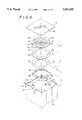
- FIG. 4is an exploded perspective view showing the embodiment of the present invention.
- FIG. 5is a section showing another embodiment of the present invention.
- an upper cartridge case A and a lower ink jet head Bare fixed in a stacked state.
- the cartridge case Ais constructed, as shown in FIGS. 1 and 4, by housing a sponge impregnated with ink 1 and by sealing it by a cover 2.
- This cover 2is formed with an air vent hole 2a.
- the cartridge case Ais equipped outside of its wall 3 opposed to the cover 2 with a head housing portion 3a.
- the wall 3is formed with an ink hole 3b for providing the communication with the inside of the cartridge case A and the head housing portion 3a.
- the wall 3is further formed with a pipe 3c which is directed toward the head housing portion 3a for communicating with the ink hole 3b.
- a filter 3dfor filtering dust or the like in the ink to prevent it from stealing into the ink jet head B.
- the cartridge case Aas shown in FIG. 4, is formed partially in its outer circumference with a recess 3e for housing the leads of an electric connecting member C.
- the cartridge case Ais further formed with recesses 3f and 3f for positioning members to be housed in the head housing portion 3a.
- the ink jet head Bis exemplified in FIGS. 1 to 4.
- the example shown in FIGS. 1 to 3is a head having twelve nozzles
- the example shown in FIG. 4is a head having twenty two nozzles.
- These headshave substantially identical constructions although their contours and passage shapes are slightly different.
- a passage substrate 4 having ink passages 4a and so onis formed either by a plastic molding or by etching metal or glass.
- the passage substrate 4is also formed with nozzles 4b and so on extending through the passage substrate 4 in the thickness direction from the internal end of the ink passages 4a. As a result, the nozzles 4b and the ink passages 4a are formed to intersect substantially perpendicularly.
- the individual ink passages 4aare formed midway thereof with pressure chambers 4c and so on.
- a generally ring-shaped common ink chamber 4dwhich communicates with the outer end portions of the individual ink passages 4a.
- the passage substrate 4, as shown in FIG. 4,is formed with positioning projections 4e and 4e which are projected from the outer circumference of the passage substrate 4.
- a vibrating plate 5To the face of the passage substrate 4 at the side of the ink passages 4a, there is bonded a vibrating plate 5.
- This vibrating plate 5is formed with ink supply holes 5a facing the ink holes 3b of the cartridge case A and communicating with the common ink chamber 4d of the passage substrate 4.
- an electric conductive adhesive piezoelectric elementsacting as ink ejecting means 6 and so on, each of which is formed on its two faces with electrodes 6a and 6b.
- the vibrating plate 5is made of an electric conductive material such as phosphor bronze so that the individual electrodes 6b bonded to the vibrating plates act as common ones.
- the flexible cable 7acting as the electric connecting member C.
- the flexible cable 7is formed with the not-shown electric conductive patterns and the common conductive pattern for supplying the electric power to the piezoelectric elements 6 and has its one end portion pressed onto the electrodes 6a of the piezoelectric elements 6 and the vibrating plate 5 and its other end portion led out of the cartridge case A.
- the flexible cable 7, as shown in FIG. 4is formed in its outer circumference with positioning notches 7a.
- a pressure rubber 8 acting as an elastic memberis sandwiched between the flexible cable 7 and the wall 3 of the cartridge case A.
- This pressure rubber 8is formed with: recesses 8a to be fitted on the pipes 3c; and through holes 8b to communicate with the ink holes 3b thereby to provide the communication between the ink holes 3b and the ink supply holes 5a and to push the common conductive pattern of the flexible cable 7 onto the vibrating plate 5.
- the pressure rubber 8is integrally formed with pressure portions 8c for pushing the conductive pattern 7 of the flexible cable 7 onto the electrodes 6a of the piezoelectric elements 6.
- a supporting plate 9which is made of a metal plate.
- This supporting plate 9is formed with holes 9a facing the nozzles 4b and so on.
- the cartridge case A having the ink 1 housed thereinis placed with its head housing portion 3a directed upward, and the pressure rubber 8 is stacked by having its recesses 8a fitted on the pipes 3c.
- the pressure rubber 8there is stacked the flexible cable 7 by positioning it with the positioning notches 7a.
- the ink jet head Bis stacked on the flexible cable 7 by positioning it with the positioning projections 4e.
- the supporting plate 9is fixed on the cartridge case A by using the not-shown fixing screws. Then, the pressure rubber 8 comes into the pressed state to ensure the electric connections between the piezoelectric elements 6 and the flexible cable 7 and between the vibrating plate 5 and the flexible cable 7.
- the common conductive pattern of the flexible cable 7comes into abutment against the vibrating plate 5, through which it is electrically connected with the electrodes 6b on one face of the piezoelectric elements 6.
- the electric conductive pattern of the flexible cable 7is held in abutment against the electrodes 6a on the other face of the piezoelectric elements 6 by the pressure portions 8c.
- the electric powercan be supplied selectively to the individual piezoelectric elements.
- the communications between the through holes 8b and the ink holes 3bare attained without any ink leakage.
- the ink support holes 5aare enabled to communicate with the through holes 8b and the ink holes 3b so that the ink 1 can be supplied to the common ink chamber 4d and ejected through the ink passages 4a from the nozzles 4b.
- the stacking direction, the direction to supply the ink from the cartridge case A to the ink supply holes 5a and the direction to inject the ink from the nozzles 4bare substantially identical.
- FIG. 5shows another embodiment, in which the electric connecting member C is made of a metal lead frame 17 in place of the flexible cable.
- the metal lead frame 17is molded in the cartridge case A and has its inner end portion equipped with an electric connecting contact members 17a elastically contacting with the electrodes 6a of the piezoelectric elements 6 and a common contact member 17b elastically contacting with the vibrating plate 5 and its outer end portion exposed from the outer circumferential wall of the cartridge case A to the outside.
- the pressure rubberis replaced by packings 18 acting as elastic tic members to be fitted on the pipes 3c. These packings 18 are formed input supply holes 18a for providing the communications between the ink holes 3b and the ink supply holes 5a.
- the remaining constructionis similar to that of the foregoing embodiment and has its components designated at the identical reference numerals.
- the ink jet head Bmay be held under pressure in the cartridge case A without using the supporting plate 9 such that they may be fixed by means of adhesion or ultrasonic bonding.
- the ink flow direction from the cartridge case A to the ink jet head B and the stacking direction of the twoare substantially aligned.
- the ink flowcan be retained merely by making the stack such that the ink holes 3b of the cartridge case A and the ink supply holes 5a of the ink jet head B face each other, so that the manufacture process can be remarkably simplified because no other members need not be disposed outside.
- the elastic members 8 and 18,which may be stacked like the cartridge case A and the ink jet head B so that the manufacture can be simplified.
- the cartridge case and the ink jet headare fixed in the stacked state, and this stacking direction, the ink supply direction from the cartridge case to the ink supply holes and the ink ejecting direction from the nozzles are made substantially identical.
- the cartridge case and the ink jet headcan be bonded merely by stacking the latter on the former, and the ink flow can be retained without using any other members, so that the assembly can be improved and suited for the automation.
- the spacecan be reduced not only in the two-dimensional direction but also in the thickness direction so that the ink can be fed at the shortest distance without any leakage from the cartridge case to the ink jet head.
- the ink Jet Readcan be constructed merely by stacking the individual members sequentially in the same direction so that the assembly is better improve and can be easily automated while simplifying the supply of the electric power.
- the elastic members for sealing and providing the communications between the ink holes of the cartridge case and the ink supply holes of the ink jet headand the elastic members are integrally equipped with the pressure portions for pressing the electric connecting members onto the ink ejecting means.
- the ink jet headis equipped with the supporting plate on its nozzle face so that the ink passages are not damaged.
Landscapes
- Ink Jet (AREA)
- Particle Formation And Scattering Control In Inkjet Printers (AREA)
Abstract
Description
Claims (4)
Applications Claiming Priority (2)
| Application Number | Priority Date | Filing Date | Title |
|---|---|---|---|
| JP4-049175 | 1992-03-06 | ||
| JP04917592AJP3232626B2 (en) | 1992-03-06 | 1992-03-06 | Inkjet head block |
Publications (1)
| Publication Number | Publication Date |
|---|---|
| US5581288Atrue US5581288A (en) | 1996-12-03 |
Family
ID=12823722
Family Applications (1)
| Application Number | Title | Priority Date | Filing Date |
|---|---|---|---|
| US08/027,122Expired - LifetimeUS5581288A (en) | 1992-03-06 | 1993-03-05 | Ink jet head block |
Country Status (2)
| Country | Link |
|---|---|
| US (1) | US5581288A (en) |
| JP (1) | JP3232626B2 (en) |
Cited By (32)
| Publication number | Priority date | Publication date | Assignee | Title |
|---|---|---|---|---|
| US5724076A (en)* | 1994-04-04 | 1998-03-03 | Rohm Co., Ltd. | Out-of-ink detector and ink jet printer |
| EP0849085A3 (en)* | 1996-12-17 | 1999-02-17 | Nec Corporation | Ink cartridge |
| US5874971A (en)* | 1995-08-22 | 1999-02-23 | Seiko Epson Corporation | Ink jet head connection unit, an ink jet cartridge, and an assembly method thereof |
| EP0832747A3 (en)* | 1996-08-30 | 1999-03-10 | Canon Kabushiki Kaisha | A method for coupling liquid jet head units, a liquid jet head unit, and a liquid jet head cartridge |
| US6027208A (en)* | 1995-09-29 | 2000-02-22 | Rohm Co. Ltd. | Ink jet printhead with passage forming panel and vibration plate |
| US6193362B1 (en) | 1995-08-22 | 2001-02-27 | Seiko Epson Corporation | Connection unit for an inkjet head, and an inkjet cartridge and inkjet printer using the same |
| EP1024005A3 (en)* | 1999-01-29 | 2001-03-07 | Seiko Epson Corporation | Ink jet recording head and method of manufacturing the same |
| US6267472B1 (en) | 1998-06-19 | 2001-07-31 | Lexmark International, Inc. | Ink jet heater chip module with sealant material |
| WO2001025018A3 (en)* | 1999-10-05 | 2001-12-06 | Spectra Inc | Piezoelectric ink jet module with seal |
| US6338550B1 (en)* | 1994-02-15 | 2002-01-15 | Rohm, Co., Ltd. | Inkjet printing head with oval flexible cable configured to be received within oval hollow portion |
| US6416172B2 (en)* | 2000-01-11 | 2002-07-09 | Samsung Electronics Co., Ltd. | Ink-jet head device with a multi-stacked PZT actuator |
| US6450627B1 (en)* | 1994-03-21 | 2002-09-17 | Spectra, Inc. | Simplified ink jet head |
| EP1336491A1 (en)* | 2002-02-18 | 2003-08-20 | Brother Kogyo Kabushiki Kaisha | Ink-jet head and ink-jet printer having the ink-jet head |
| US6682181B1 (en)* | 1994-03-21 | 2004-01-27 | Spectra, Inc. | Ink jet head containing a carbon member |
| EP1257421A4 (en)* | 1999-12-09 | 2004-07-28 | Silverbrook Res Pty Ltd | An ink supply device for a four color modular printhead |
| US20040189757A1 (en)* | 2003-03-28 | 2004-09-30 | Takahiro Yamada | Ink jet printer head and method of producing ink jet printer head |
| US20050083379A1 (en)* | 2003-08-14 | 2005-04-21 | Brother Kogyo Kabushiki Kaisha | Ink-jet head |
| US20050162472A1 (en)* | 1999-12-09 | 2005-07-28 | Kia Silverbrook | Printhead module |
| US20050231554A1 (en)* | 2001-11-30 | 2005-10-20 | Brother Kogyo Kabushiki Kaisha | Ink-jet head having passage unit and actuator units attached to the passage unit, and ink-jet printer having the ink-jet head |
| US20060171823A1 (en)* | 2005-01-14 | 2006-08-03 | Brother Kogyo Kabushiki Kaisha | Inkjet head |
| US20070109356A1 (en)* | 1999-12-09 | 2007-05-17 | Silverbrook Research Pty Ltd | Modular printhead assembly with reservoir mounted printhead modules |
| US20070263041A1 (en)* | 2006-05-08 | 2007-11-15 | Seiko Epson Corporation | Liquid-jet head and liquid-jet apparatus |
| US20080079782A1 (en)* | 2006-09-29 | 2008-04-03 | Brother Kogyo Kabushiki Kaisha | Inkjet head |
| US20080259134A1 (en)* | 2007-04-20 | 2008-10-23 | Hewlett-Packard Development Company Lp | Print head laminate |
| US20090102900A1 (en)* | 2003-02-19 | 2009-04-23 | Seiko Epson Corporation | Liquid storage unit and liquid ejecting apparatus |
| EP2213456A3 (en)* | 2002-02-18 | 2010-09-01 | Brother Kogyo Kabushiki Kaisha | Ink-jet head and ink-jet printer having ink-jet head |
| US7988247B2 (en) | 2007-01-11 | 2011-08-02 | Fujifilm Dimatix, Inc. | Ejection of drops having variable drop size from an ink jet printer |
| US8459768B2 (en) | 2004-03-15 | 2013-06-11 | Fujifilm Dimatix, Inc. | High frequency droplet ejection device and method |
| US20130147882A1 (en)* | 2011-12-13 | 2013-06-13 | Seiko Epson Corporation | Liquid Ejecting Head and Liquid Ejecting Apparatus |
| US8491076B2 (en) | 2004-03-15 | 2013-07-23 | Fujifilm Dimatix, Inc. | Fluid droplet ejection devices and methods |
| US8708441B2 (en) | 2004-12-30 | 2014-04-29 | Fujifilm Dimatix, Inc. | Ink jet printing |
| EP3178655A1 (en)* | 2015-12-08 | 2017-06-14 | SII Printek Inc | Liquid jet head, liquid jet recording device, and method of manufacturing liquid jet head |
Families Citing this family (3)
| Publication number | Priority date | Publication date | Assignee | Title |
|---|---|---|---|---|
| US5755909A (en)* | 1996-06-26 | 1998-05-26 | Spectra, Inc. | Electroding of ceramic piezoelectric transducers |
| JP4991191B2 (en)* | 2006-06-30 | 2012-08-01 | 株式会社東芝 | Droplet ejecting head and droplet ejecting apparatus |
| KR101141405B1 (en)* | 2009-12-04 | 2012-05-03 | 삼성전기주식회사 | Inkjet head package |
Citations (6)
| Publication number | Priority date | Publication date | Assignee | Title |
|---|---|---|---|---|
| US4521788A (en)* | 1981-12-26 | 1985-06-04 | Konishiroku Photo Industry Co., Ltd. | Ink jet printing head |
| US4528575A (en)* | 1980-12-30 | 1985-07-09 | Fujitsu Limited | Ink jet printing head |
| US4677447A (en)* | 1986-03-20 | 1987-06-30 | Hewlett-Packard Company | Ink jet printhead having a preloaded check valve |
| US4727384A (en)* | 1984-07-30 | 1988-02-23 | Canon Kabushiki Kaisha | Liquid jet recording head |
| US4771295A (en)* | 1986-07-01 | 1988-09-13 | Hewlett-Packard Company | Thermal ink jet pen body construction having improved ink storage and feed capability |
| JPH04292947A (en)* | 1991-03-22 | 1992-10-16 | Brother Ind Ltd | Liquid drop jetting device |
- 1992
- 1992-03-06JPJP04917592Apatent/JP3232626B2/ennot_activeExpired - Fee Related
- 1993
- 1993-03-05USUS08/027,122patent/US5581288A/ennot_activeExpired - Lifetime
Patent Citations (7)
| Publication number | Priority date | Publication date | Assignee | Title |
|---|---|---|---|---|
| US4528575A (en)* | 1980-12-30 | 1985-07-09 | Fujitsu Limited | Ink jet printing head |
| US4521788A (en)* | 1981-12-26 | 1985-06-04 | Konishiroku Photo Industry Co., Ltd. | Ink jet printing head |
| US4727384A (en)* | 1984-07-30 | 1988-02-23 | Canon Kabushiki Kaisha | Liquid jet recording head |
| US4677447A (en)* | 1986-03-20 | 1987-06-30 | Hewlett-Packard Company | Ink jet printhead having a preloaded check valve |
| US4771295A (en)* | 1986-07-01 | 1988-09-13 | Hewlett-Packard Company | Thermal ink jet pen body construction having improved ink storage and feed capability |
| US4771295B1 (en)* | 1986-07-01 | 1995-08-01 | Hewlett Packard Co | Thermal ink jet pen body construction having improved ink storage and feed capability |
| JPH04292947A (en)* | 1991-03-22 | 1992-10-16 | Brother Ind Ltd | Liquid drop jetting device |
Cited By (104)
| Publication number | Priority date | Publication date | Assignee | Title |
|---|---|---|---|---|
| US6338550B1 (en)* | 1994-02-15 | 2002-01-15 | Rohm, Co., Ltd. | Inkjet printing head with oval flexible cable configured to be received within oval hollow portion |
| US6682181B1 (en)* | 1994-03-21 | 2004-01-27 | Spectra, Inc. | Ink jet head containing a carbon member |
| US6450627B1 (en)* | 1994-03-21 | 2002-09-17 | Spectra, Inc. | Simplified ink jet head |
| US5724076A (en)* | 1994-04-04 | 1998-03-03 | Rohm Co., Ltd. | Out-of-ink detector and ink jet printer |
| US5874971A (en)* | 1995-08-22 | 1999-02-23 | Seiko Epson Corporation | Ink jet head connection unit, an ink jet cartridge, and an assembly method thereof |
| US5997125A (en)* | 1995-08-22 | 1999-12-07 | Seiko Epson Corporation | Ink jet head connection unit, an ink jet cartridge, and an assembly method thereof |
| US6074036A (en)* | 1995-08-22 | 2000-06-13 | Seiko Epson Corporation | Ink jet head connection unit, an ink jet cartridge, and an assembly method thereof |
| US6193362B1 (en) | 1995-08-22 | 2001-02-27 | Seiko Epson Corporation | Connection unit for an inkjet head, and an inkjet cartridge and inkjet printer using the same |
| US6027208A (en)* | 1995-09-29 | 2000-02-22 | Rohm Co. Ltd. | Ink jet printhead with passage forming panel and vibration plate |
| US6293652B1 (en) | 1996-08-30 | 2001-09-25 | Canon Kabushiki Kaisha | Method for coupling liquid jet head units, a liquid jet head unit, and a liquid jet head cartridge |
| EP0832747A3 (en)* | 1996-08-30 | 1999-03-10 | Canon Kabushiki Kaisha | A method for coupling liquid jet head units, a liquid jet head unit, and a liquid jet head cartridge |
| AU732002B2 (en)* | 1996-08-30 | 2001-04-12 | Canon Kabushiki Kaisha | A method for coupling liquid jet head units, a liquid jet head unit, and a liquid jet head cartridge |
| AU722862B2 (en)* | 1996-12-17 | 2000-08-10 | Nec Corporation | Ink cartridge |
| EP0849085A3 (en)* | 1996-12-17 | 1999-02-17 | Nec Corporation | Ink cartridge |
| CN1072119C (en)* | 1996-12-17 | 2001-10-03 | 日本电气株式会社 | Ink box |
| US6267472B1 (en) | 1998-06-19 | 2001-07-31 | Lexmark International, Inc. | Ink jet heater chip module with sealant material |
| EP1024005A3 (en)* | 1999-01-29 | 2001-03-07 | Seiko Epson Corporation | Ink jet recording head and method of manufacturing the same |
| US6382778B1 (en)* | 1999-01-29 | 2002-05-07 | Seiko Epson Corporation | Ink jet recording head and method of manufacturing the same |
| US8491100B2 (en) | 1999-10-05 | 2013-07-23 | Fujifilm Dimatix, Inc. | Piezoelectric ink jet module with seal |
| US7011396B2 (en) | 1999-10-05 | 2006-03-14 | Dimatix, Inc. | Piezoelectric ink jet module with seal |
| EP2253473A1 (en)* | 1999-10-05 | 2010-11-24 | Fujifilm Dimatix, Inc. | Piezoelectric ink jet module |
| WO2001025018A3 (en)* | 1999-10-05 | 2001-12-06 | Spectra Inc | Piezoelectric ink jet module with seal |
| US6755511B1 (en) | 1999-10-05 | 2004-06-29 | Spectra, Inc. | Piezoelectric ink jet module with seal |
| EP1439065A1 (en)* | 1999-10-05 | 2004-07-21 | Spectra, Inc. | Piezoelectric ink jet printing module |
| EP2088000A1 (en) | 1999-10-05 | 2009-08-12 | Fujifilm Dimatix, Inc. | Piezoelectric ink jet module |
| US20090079801A1 (en)* | 1999-10-05 | 2009-03-26 | Fujifilm Dimatix, Inc., A Delaware Corporation | Piezoelectric ink jet module with seal |
| US20050030341A1 (en)* | 1999-10-05 | 2005-02-10 | Spectra, Inc., A Delaware Corporation | Piezoelectric ink jet module with seal |
| US7478899B2 (en) | 1999-10-05 | 2009-01-20 | Fujifilm Dimatix, Inc. | Piezoelectric ink jet module with seal |
| EP1752295A1 (en)* | 1999-10-05 | 2007-02-14 | Dimatix, Inc. | Piezoelectric ink jet module |
| US7841699B2 (en) | 1999-12-09 | 2010-11-30 | Silverbrook Research Pty Ltd | Modular ink jet printhead assembly with obliquely overlapping printheads |
| EP1257421A4 (en)* | 1999-12-09 | 2004-07-28 | Silverbrook Res Pty Ltd | An ink supply device for a four color modular printhead |
| US8376519B2 (en) | 1999-12-09 | 2013-02-19 | Zamtec Ltd | Printhead having assembly of printhead modules |
| US20050243138A1 (en)* | 1999-12-09 | 2005-11-03 | Silverbrook Research Pty Ltd | Printhead assembly with modular detachable printheads |
| US20050243137A1 (en)* | 1999-12-09 | 2005-11-03 | Silverbrook Research Pty Ltd | Ink jet printhead assembly with modular printheads |
| US6962410B2 (en) | 1999-12-09 | 2005-11-08 | Silverbrook Research Pty Ltd | Ink supply device |
| US6962409B2 (en) | 1999-12-09 | 2005-11-08 | Silverbrook Research Pty Ltd | Ink filling arrangement for elongate printhead |
| US20050259129A1 (en)* | 1999-12-09 | 2005-11-24 | Silverbrook Research Pty Ltd | Printhead assembly with printhead modules |
| US8328332B2 (en) | 1999-12-09 | 2012-12-11 | Zamtec Limited | Modular printhead assembly with releasable printhead modules |
| US20050110845A1 (en)* | 1999-12-09 | 2005-05-26 | Kia Silverbrook | Modular printhead assembly incorporating ink storage and distribution assemblies |
| US7025446B2 (en) | 1999-12-09 | 2006-04-11 | Silverbrook Research Pty Ltd | Printhead assembly with ink distribution and feed structures spanning a pagewidth |
| US7027080B2 (en) | 1999-12-09 | 2006-04-11 | Silverbrook Research Pty Ltd | Modular printhead assembly incorporating ink storage distribution assemblies |
| US7033008B2 (en) | 1999-12-09 | 2006-04-25 | Silverbrook Research Pty Ltd | Ink reservoir for printhead chip |
| US8118404B2 (en) | 1999-12-09 | 2012-02-21 | Silverbrook Research Pty Ltd | Printing arrangement having printhead and ink supply assemblies |
| US7097292B2 (en) | 1999-12-09 | 2006-08-29 | Silverbrook Research Pty Ltd | Printhead assembly with printhead modules |
| US7784907B2 (en) | 1999-12-09 | 2010-08-31 | Silverbrook Research Pty Ltd | Printhead assembly with replaceable printhead modules |
| US7145592B2 (en) | 1999-12-09 | 2006-12-05 | Silverbrook Research Pty Ltd | Ink jet printhead assembly with modular printheads |
| US20060279608A1 (en)* | 1999-12-09 | 2006-12-14 | Silverbrook Research Pty Ltd | Modular printhead assembly with releasable printhead modules |
| US7152955B2 (en) | 1999-12-09 | 2006-12-26 | Silverbrook Research Pty Ltd | Printhead assembly with modular detachable printheads |
| US20050110846A1 (en)* | 1999-12-09 | 2005-05-26 | Kia Silverbrook | Printhead assembly with ink distribution and feed structures spanning a pagewidth |
| US7182441B2 (en) | 1999-12-09 | 2007-02-27 | Silverbrook Research Pty Ltd | Printhead module |
| US20070052755A1 (en)* | 1999-12-09 | 2007-03-08 | Silverbrook Research Pty Ltd | Modular ink jet printhead assembly with obliquely overlapping printheads |
| US20070058000A1 (en)* | 1999-12-09 | 2007-03-15 | Silverbrook Research Pty Ltd | Modular printhead with closely spaced rows in media feed direction |
| US20070064057A1 (en)* | 1999-12-09 | 2007-03-22 | Silverbrook Research Pty Ltd | Printhead module for an inkjet printhead assembly incorporating a printhead integrated circuit |
| US20070109356A1 (en)* | 1999-12-09 | 2007-05-17 | Silverbrook Research Pty Ltd | Modular printhead assembly with reservoir mounted printhead modules |
| US7708380B2 (en) | 1999-12-09 | 2010-05-04 | Silverbrook Research Pty Ltd | Printhead module for an inkjet printhead assembly incorporating a printhead integrated circuit |
| US7677698B2 (en) | 1999-12-09 | 2010-03-16 | Silverbrook Research Pty Ltd | Modular printhead assembly with reservoir mounted printhead modules |
| US20100045742A1 (en)* | 1999-12-09 | 2010-02-25 | Silverbrook Research Pty Ltd | Modular printhead assembly with releasable printhead modules |
| US7431425B2 (en) | 1999-12-09 | 2008-10-07 | Silverbrook Research Pty Ltd | Modular printhead with closely spaced rows in media feed direction |
| US20100002056A1 (en)* | 1999-12-09 | 2010-01-07 | Silverbrook Research Pty Ltd | Modular printhead assembly having reservoir mounted printhead modules |
| US7467854B2 (en) | 1999-12-09 | 2008-12-23 | Silverbrook Research Pty Ltd. | Modular ink jet printhead assembly with obliquely overlapping printheads |
| US7618122B2 (en) | 1999-12-09 | 2009-11-17 | Silverbrook Research Pty Ltd | Modular printhead assembly with releasable printhead modules |
| US20090015634A1 (en)* | 1999-12-09 | 2009-01-15 | Silverbrook Research Pty Ltd | Modular ink jet printhead assembly with obliquely overlapping printheads |
| US20050162472A1 (en)* | 1999-12-09 | 2005-07-28 | Kia Silverbrook | Printhead module |
| US20090085977A1 (en)* | 1999-12-09 | 2009-04-02 | Silverbrook Research Pty Ltd | Printing Arrangement Having Printhead And Ink Supply Assemblies |
| US6416172B2 (en)* | 2000-01-11 | 2002-07-09 | Samsung Electronics Co., Ltd. | Ink-jet head device with a multi-stacked PZT actuator |
| US8684496B2 (en) | 2001-11-30 | 2014-04-01 | Brother Kogyo Kabushiki Kaisha | Ink-jet head having passage unit and actuator units attached to the passage unit, and ink-jet printer having the ink-jet head |
| US8118402B2 (en) | 2001-11-30 | 2012-02-21 | Brother Kogyo Kabushiki Kaisha | Ink-jet head having passage unit and actuator units attached to the passage unit, and ink-jet printer having the ink-jet head |
| US20090073227A1 (en)* | 2001-11-30 | 2009-03-19 | Brother Kogyo Kabushiki Kaisha | Ink-jet head having passage unit and actuator units attached to the passage unit, and ink-jet printer having the ink-jet head |
| US20080316257A1 (en)* | 2001-11-30 | 2008-12-25 | Brother Kogyo Kabushiki Kaisha | Ink-jet head having passage unit and actuator units attached to the passage unit, and ink-jet printer having the ink-jet head |
| US11305536B2 (en) | 2001-11-30 | 2022-04-19 | Brother Kogyo Kabushiki Kaisha | Ink-jet head having passage unit and actuator units attached to the passage unit, and ink-jet printer having the ink-jet head |
| US10821730B2 (en) | 2001-11-30 | 2020-11-03 | Brother Kogyo Kabushiki Kaisha | Ink-jet head having passage unit and actuator units attached to the passage unit, and ink-jet printer having the ink-jet head |
| US20050231554A1 (en)* | 2001-11-30 | 2005-10-20 | Brother Kogyo Kabushiki Kaisha | Ink-jet head having passage unit and actuator units attached to the passage unit, and ink-jet printer having the ink-jet head |
| US10357968B2 (en) | 2001-11-30 | 2019-07-23 | Brother Kogyo Kabushiki Kaisha | Ink-jet head having passage unit and actuator units attached to the passage unit, and ink-jet printer having the ink-jet head |
| US9925774B2 (en) | 2001-11-30 | 2018-03-27 | Brother Kogyo Kabushiki Kaisha | Ink-jet head having passage unit and actuator units attached to the passage unit, and ink-jet printer having the ink-jet head |
| US8025369B2 (en) | 2001-11-30 | 2011-09-27 | Brother Kogyo Kabushiki Kaisha | Ink-jet head and ink-jet printer having ink-jet head |
| US8393711B2 (en) | 2001-11-30 | 2013-03-12 | Brother Kogyo Kabushiki Kaisha | Ink-jet head having passage unit and actuator units attached to the passage unit, and ink-jet printer having the ink-jet head |
| US9718271B2 (en) | 2001-11-30 | 2017-08-01 | Brother Kogyo Kabushiki Kaisha | Ink-jet head having passage unit and actuator units attached to the passage unit, and ink-jet printer having the ink-jet head |
| US9114616B2 (en) | 2001-11-30 | 2015-08-25 | Brother Kogyo Kabushiki Kaisha | Ink-jet head having passage unit and actuator units attached to the passage unit, and ink-jet printer having the ink-jet head |
| US7891781B2 (en) | 2001-11-30 | 2011-02-22 | Brother Kogyo Kabushiki Kaisha | Ink-jet head having passage unit and actuator units attached to the passage unit, and ink-jet printer having the ink-jet head |
| EP1336491A1 (en)* | 2002-02-18 | 2003-08-20 | Brother Kogyo Kabushiki Kaisha | Ink-jet head and ink-jet printer having the ink-jet head |
| US20030156157A1 (en)* | 2002-02-18 | 2003-08-21 | Brother Kogyo Kabushiki Kaisha | Ink-jet head and ink-jet printer having the ink-jet head |
| EP2213456A3 (en)* | 2002-02-18 | 2010-09-01 | Brother Kogyo Kabushiki Kaisha | Ink-jet head and ink-jet printer having ink-jet head |
| US7004565B2 (en) | 2002-02-18 | 2006-02-28 | Brother Kogyo Kabushiki Kaisha | Ink-jet head and ink-jet printer having the ink-jet head |
| US20090102900A1 (en)* | 2003-02-19 | 2009-04-23 | Seiko Epson Corporation | Liquid storage unit and liquid ejecting apparatus |
| US8083101B2 (en)* | 2003-02-19 | 2011-12-27 | Seiko Epson Corporation | Liquid storage unit and liquid ejecting apparatus |
| US7131716B2 (en)* | 2003-03-28 | 2006-11-07 | Brother Kogyo Kabushiki Kaisha | Ink jet printer head and method of producing ink jet printer head |
| US20040189757A1 (en)* | 2003-03-28 | 2004-09-30 | Takahiro Yamada | Ink jet printer head and method of producing ink jet printer head |
| US7419245B2 (en)* | 2003-08-14 | 2008-09-02 | Brother Kogyo Kabushiki Kaisha | Ink-jet head |
| US20050083379A1 (en)* | 2003-08-14 | 2005-04-21 | Brother Kogyo Kabushiki Kaisha | Ink-jet head |
| US8491076B2 (en) | 2004-03-15 | 2013-07-23 | Fujifilm Dimatix, Inc. | Fluid droplet ejection devices and methods |
| US8459768B2 (en) | 2004-03-15 | 2013-06-11 | Fujifilm Dimatix, Inc. | High frequency droplet ejection device and method |
| US8708441B2 (en) | 2004-12-30 | 2014-04-29 | Fujifilm Dimatix, Inc. | Ink jet printing |
| US9381740B2 (en) | 2004-12-30 | 2016-07-05 | Fujifilm Dimatix, Inc. | Ink jet printing |
| US7798614B2 (en)* | 2005-01-14 | 2010-09-21 | Brother Kogyo Kabushiki Kaisha | Inkjet head |
| US20060171823A1 (en)* | 2005-01-14 | 2006-08-03 | Brother Kogyo Kabushiki Kaisha | Inkjet head |
| US8152283B2 (en)* | 2006-05-08 | 2012-04-10 | Seiko Epson Corporation | Liquid-jet head and liquid-jet apparatus |
| US20070263041A1 (en)* | 2006-05-08 | 2007-11-15 | Seiko Epson Corporation | Liquid-jet head and liquid-jet apparatus |
| US7832827B2 (en)* | 2006-09-29 | 2010-11-16 | Brother Kogyo Kabushiki Kaisha | Inkjet head |
| US20080079782A1 (en)* | 2006-09-29 | 2008-04-03 | Brother Kogyo Kabushiki Kaisha | Inkjet head |
| EP1905592A3 (en)* | 2006-09-29 | 2010-01-20 | Brother Kogyo Kabushiki Kaisha | Inkjet head |
| US7988247B2 (en) | 2007-01-11 | 2011-08-02 | Fujifilm Dimatix, Inc. | Ejection of drops having variable drop size from an ink jet printer |
| US20080259134A1 (en)* | 2007-04-20 | 2008-10-23 | Hewlett-Packard Development Company Lp | Print head laminate |
| US20130147882A1 (en)* | 2011-12-13 | 2013-06-13 | Seiko Epson Corporation | Liquid Ejecting Head and Liquid Ejecting Apparatus |
| EP3178655A1 (en)* | 2015-12-08 | 2017-06-14 | SII Printek Inc | Liquid jet head, liquid jet recording device, and method of manufacturing liquid jet head |
Also Published As
| Publication number | Publication date |
|---|---|
| JPH05246044A (en) | 1993-09-24 |
| JP3232626B2 (en) | 2001-11-26 |
Similar Documents
| Publication | Publication Date | Title |
|---|---|---|
| US5581288A (en) | Ink jet head block | |
| US6729717B2 (en) | Ink-jet head and method of fabricating same | |
| EP0759362B1 (en) | Ink jet head connection unit, ink jet cartridge and method of assembling the ink jet head connection unit | |
| CA2386737C (en) | Piezoelectric ink jet module with seal | |
| EP0750987B1 (en) | Actuator for an ink jet print head | |
| US7669982B2 (en) | Laminated and bonded structure of plates | |
| EP0875380B1 (en) | Ink jet recording head | |
| EP1506867B1 (en) | Ink-jet head | |
| JP2001219555A (en) | Ink jet recording head | |
| JP2005205810A (en) | Inkjet head | |
| EP1506865B1 (en) | Inkjet head | |
| JP2007090870A (en) | Liquid discharge head and manufacturing method thereof | |
| EP1393906B1 (en) | Inkjet head having laminated piezoelectric actuator | |
| US6623094B2 (en) | Ink jet recording device | |
| US20030210305A1 (en) | Ink-jet head | |
| EP1506870B1 (en) | Inkjet head | |
| US6601949B1 (en) | Actuator unit for ink jet recording head | |
| EP0799699B1 (en) | Laminated ink jet recording head | |
| JP3094672B2 (en) | Inkjet head | |
| JP4682552B2 (en) | Inkjet head | |
| US7121649B2 (en) | Ink-jet head and reservoir unit included in ink-jet head | |
| US20050278951A1 (en) | Manufacturing method of ink-jet head | |
| JP2001347659A (en) | Inkjet recording head | |
| US7219981B2 (en) | Ink-jet head and producing method thereof | |
| US7798614B2 (en) | Inkjet head |
Legal Events
| Date | Code | Title | Description |
|---|---|---|---|
| AS | Assignment | Owner name:SEIKOSHA CO., LTD., JAPAN Free format text:ASSIGNMENT OF ASSIGNORS INTEREST;ASSIGNORS:SHIMIZU, YUKIHARU;HAYAKAWA, TSUYOSHI;KOJIMA, HIROYUKI;AND OTHERS;REEL/FRAME:006760/0397 Effective date:19930819 | |
| AS | Assignment | Owner name:SEIKOSHA CO., LTD., JAPAN Free format text:ASSIGNMENT OF ASSIGNORS INTEREST;ASSIGNORS:SHIMIZU, YUKIHARU;HAYAKAWA, TSUYOSHI;KOJIMA, HIROYUKI;AND OTHERS;REEL/FRAME:006950/0716 Effective date:19930819 | |
| AS | Assignment | Owner name:SEIKO PRECISION INC., JAPAN Free format text:ASSIGNMENT OF ASSIGNORS INTEREST;ASSIGNOR:SEIKOSHA CO., LTD;REEL/FRAME:008100/0089 Effective date:19960329 | |
| STCF | Information on status: patent grant | Free format text:PATENTED CASE | |
| FPAY | Fee payment | Year of fee payment:4 | |
| FPAY | Fee payment | Year of fee payment:8 | |
| AS | Assignment | Owner name:SEIKO EPSON CORPORATION, JAPAN Free format text:ASSIGNMENT OF ASSIGNORS INTEREST;ASSIGNOR:SEIKO PRECISION INC.;REEL/FRAME:020638/0387 Effective date:20080218 | |
| FPAY | Fee payment | Year of fee payment:12 |