US5579054A - System and method for creating high-quality stills from interlaced video - Google Patents
System and method for creating high-quality stills from interlaced videoDownload PDFInfo
- Publication number
- US5579054A US5579054AUS08/426,309US42630995AUS5579054AUS 5579054 AUS5579054 AUS 5579054AUS 42630995 AUS42630995 AUS 42630995AUS 5579054 AUS5579054 AUS 5579054A
- Authority
- US
- United States
- Prior art keywords
- field
- motion
- fields
- interpolated
- dominant
- Prior art date
- Legal status (The legal status is an assumption and is not a legal conclusion. Google has not performed a legal analysis and makes no representation as to the accuracy of the status listed.)
- Expired - Lifetime
Links
Images


Classifications
- H—ELECTRICITY
- H04—ELECTRIC COMMUNICATION TECHNIQUE
- H04N—PICTORIAL COMMUNICATION, e.g. TELEVISION
- H04N5/00—Details of television systems
- H04N5/44—Receiver circuitry for the reception of television signals according to analogue transmission standards
- H04N5/4448—Receiver circuitry for the reception of television signals according to analogue transmission standards for frame-grabbing
Definitions
- This inventionrelates to a method and system for obtaining a high quality still image from multiple fields of an interlaced video signal, i.e., deinterlacing, in the presence of both dominant motion, such as camera zoom, rotation, pan, or jitter, and local motion of independently moving objects.
- the prior artaddresses the problem of deinterlacing an even (or an odd) field by estimating the missing odd (or even) lines.
- a well-known methodis to merge the even and odd fields, i.e., to fill in the missing lines of the odd (even) field by the lines of the neighboring even (odd) field.
- This simple mechanismcauses spatial "judder" artifacts at those image regions that contain moving objects (objects that move within the time interval of two successive fields). Merging, however, provides the best spatial resolution at steady image regions.
- Another approach to deinterlacingis to concentrate on a single field only (e.g., the odd field) and interpolate the missing lines using spatial interpolation.
- a simple interpolation techniqueis vertical linear interpolation where an average of the available pixel values above and below the missing pixel is assigned to the missing pixel. This method may cause artifacts if the missing pixel is over an edge whose orientation is not vertical.
- an contour-sensitive spatial interpolation methodis proposed in M. Isnardi, "Modeling the Television Process," Technical Report No. 515, Massachusetts Institute of Technology, 1986, pages 161 to 163. This method attempts to find the orientation of the image gradient at the missing pixel. Interpolation is then performed using image values that are along this orientation in order not to "cross an edge" and cause artifacts.
- a method that is potentially more effectiveis a hybrid method where the deinterlacing process switches, on a pixel-by-pixel basis, between merging and spatial interpolation depending on the dynamics of the missing pixel, so that the advantages of merging in steady regions are fully maintained.
- a motion detection schemeshould be used to classify the missing pixel as a "moving pixel" or "steady pixel".
- Bennett et al.disclose such a method that uses the pixel-by-pixel difference of neighboring fields with the same polarity (e.g., even fields) that follow and precede the field that will be deinterlaced (e.g., an odd field) to perform motion detection, and then switch between merging and vertical interpolation depending on the presence and absence of motion that is determined by thresholding the difference values.
- This particular approachmay falsely detect "no motion” if the scene is such that the gray levels of the pixels being compared in the two neighboring fields are similar although there is motion in the scene.
- Such a situationmay happen, for instance, in case of scenes that contain a small object 10 moving against a uniform background 12 in the direction of arrow A as shown in FIG. 1., where fields (k), (k+1), and (k+2) represent successive interlaced video fields.
- merging of the fields (k) and (k+1) at a region of interest denoted as the box 14,will result in artifacts due to a false classification of no motion between field (k) and (k+2).
- a consecutive fourth field , field (k+3) in FIG. 1is used in motion detection, a comparison of fields (k+1) and (k+3), in addition to the comparison of fields at times (k) and (k+2), may increase the reliability of motion detection.
- Video images with dominant motionresult, for example, from the motion of hand-held cameras and/or cameras that are panned and zoomed. Since hand-held video cameras are becoming increasingly common in consumer applications, there is a growing interest in a deinterlacing method (e.g., to be used in generating good-quality prints from video) that improves the resolution via motion compensated temporal interpolation, using information contained in neighboring fields.
- a deinterlacing methode.g., to be used in generating good-quality prints from video
- a motion-compensated deinterlacing techniquethat accounts for dominant motion between fields is discussed by Wang et al. in U.S. Pat. No. 5,134,480, issued Jul. 28, 1992.
- the technique proposed by Wang et alis a time-recursive method that performs motion estimation and compensation on a local basis (for each pixel) via block matching. Due to the time-recursive nature of the method, a history of the deinterlaced versions of the fields that precede the field of interest is utilized.
- a quad-tree hierarchyis used in adjusting the block size in order to increase the accuracy of local motion estimation.
- Deinterlacingis implemented by linearly blending the results of spatial vertical interpolation and motion compensated interpolation, where motion compensation is performed using either the future field following the field of interest or the recursively deinterlaced version of the previous field.
- the object of this inventionis to provide a robust method that combines global motion compensation and motion adaptation for deinterlacing in the presence of both dominant motion, such as camera zoom, pan, or jitter, as well as independent local object motion, in order to create a high-quality still image from interlaced video.
- the objectis achieved according to one aspect of the present invention, by providing a system and a method for creating a high quality still image from a series of interlaced video fields of the type employing local motion detection between first and third fields of the series, merging the first and second fields in areas of no motion and performing spatial interpolation on the first field in areas containing local motion, wherein the system and method are improved by removing dominant motion from the second and third fields prior to local motion detection.
- the system and method of this inventionutilizes motion compensation, and special attention is directed towards producing a robust method in the sense that artifacts generated by motion estimation/compensation failures are minimized.
- the method and system of the present inventionis advantageous over the prior art in that it is capable of handling combinations of dominant and local image motion while avoiding complex computation.
- FIG. 1shows the prior art methods of detecting motion between successive fields in a video image signal
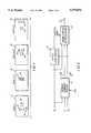
- FIG. 2is a block diagram illustrating the major steps of the invention
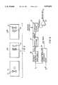
- FIG. 3is a schematic diagram depicting a system suitable for implementing the present invention.
- FIG. 4is a detailed block diagram showing the dominant-motion compensated filtering employed in the present invention.
- FIG. 5shows a series of fields demonstrating ghosting when detecting motion in dominant-motion compensated fields
- FIG. 6shows a detailed block diagram of adaptive motion detection as employed in the present invention.
- the method of the present inventiontakes three successive interlaced video fields as inputs, denoted by f 0 , f 1 , f 2 respectively, and includes three stages: (i) removing dominant motion from the video fields f 1 , and f 2 , to produce motion compensated second and third fields (16); (ii) detecting local motion in the fields using the first field and the third motion compensated field, (18); and (iii) merging the first field and the second motion compensated field in regions free of motion and performing spatial interpolation on regions of the first field where motion is detected (20).
- dominant motionis estimated over a user specified region of interest (ROI), to produce the fields f 1 MC and f 2 MC .
- ROIregion of interest
- the ROImay be chosen to represent a region in f 0 where there is global motion. Note that it is possible to choose the ROI as the entire field, at the cost of increased computation.
- the local motion detection stage 18follows, where motion detection is performed to detect regions of video moving with motions that are different from the dominant motion removed in the previous stage 16.
- the local motion detectoruses thresholding and is adaptive in the sense that the thresholding operation adapts to the scene contents as described in detail below.
- the output of the motion detection stage 18is a binary motion/no motion decision map, which is used in the last processing stage 20.
- Input devicessuch as a video camcorder/VCR 22 connected to a digitizer 24, a digital video camcorder 26, or a disk storage 28 provide a source of a video sequence of digital fields.
- the video sequence of digital fieldsis then supplied to an image processing computer system 30 that contains a computer 32 such as a Power PC, a CRT display 34 having typically SVGA or better resolution, and an operator input device 36 such as a keyboard or a mouse.
- the computeris connected to an output device such as: a printer 38 for creating a hard copy display of the high-quality still image; a storage medium 40, such as an optical disk, for storage pending eventual display of the image; or link 42 to a communication network for distributing the high-quality still image.
- an output devicesuch as: a printer 38 for creating a hard copy display of the high-quality still image; a storage medium 40, such as an optical disk, for storage pending eventual display of the image; or link 42 to a communication network for distributing the high-quality still image.
- This stagebegins by taking the input fields f 0 , f 1 , and computing the corresponding frames F 0 L , F 1 L , and F 2 L , using spatial vertical linear interpolation. This is depicted as linear interpolators 44 in the block diagram of FIG. 4. Motion is then estimated by motion estimators 46 between the frame pairs F 0 L , F 1 L , and F 0 L , F 2 L . Note that we do not assume constant-velocity, linear-trajectory motion. This is because when the dominant motion is caused by camera jitter the linear motion assumption would be violated. The global motion is modeled using an affine transformation relating the frames as
- motion trajectory filtering 48is used to compute the motion compensated fields f 1 MC and f 2 MC .
- Frames, F 1 L and F 2 Lare warped 50 using bilinear spatial interpolation to form frames F 1 W and F 2 W , both of which are estimates of the frame F 0 .
- Frames F 1 W and F 2 Ware then temporally averaged 52 to produce the frame F 0 MC , which is the motion compensated estimate of F 0 .
- the frame F 0 MCis split 54 into an odd and even fields f 1 MC and f 2 MC .
- the motion detection strategy we employis to compute the summed absolute difference (SAD) over appropriate regions in these two fields, and then apply a thresholding scheme. For example, if we denote the SAD value for the missing pixel location at (n1,n2-1) at time index k as S k (n1,n2-1), then the SAD computed over a 3 ⁇ 3 window is given by ##EQU1## where f 0 MC (n1, n2k) and f 2 MC (n1, n2k) represent the corresponding continuous fields sampled over a progressive lattice.
- the dominant motionhas already been removed, and motion detection applied between the fields f 0 and f 2 MC will be detecting the motion in objects moving independently from the dominant motion.
- motion detection applied between the fields f 0 and f 2 MCwill be detecting the motion in objects moving independently from the dominant motion.
- the motion ghost 56 of the small object 10appears in fields f 1 MC and f 2 MC .
- the ghostinghas the positive effect of allowing a 3-field method to detect the motion of fine-detailed objects independently moving against a uniform background, while only comparing a single pair of fields, since the ghost will be present for motion detection.
- the motion detection errorswill give rise to artifacts, and these will be most noticeable in image regions of low local variance, especially when no motion is detected. Therefore, in regions of low variance, the comparison threshold used in motion detection should be low, especially for accurate detection of ghosts. Second, in regions of high variance, artifacts due to motion detection will be less noticeable. Additionally, when compared to deinterlacing via an intrafield technique, it is in the regions of higher variance that motion compensated filtering will produce the greatest increase in resolution, and the greatest reduction in aliasing. Therefore, in regions of higher variance the motion detection threshold should be high. This will also provide an implicit tolerance to errors in dominant-motion estimation at such regions, the benefits of such tolerance have been discussed above.
- the proposed motion detection scheme depicted in FIG. 6has these properties.
- the first step in the motion detectionis to locally estimate 58 a sample standard deviation of field f 0 at every pixel over a 3 ⁇ 3 region, where the pixels lie at the centers of the 3 ⁇ 3 windows.
- the resultis a 2-D array, i.e., an image of standard deviation values (S.D. image).
- S.D. imagean image of standard deviation values
- the four-level standard deviation image output from the dynamic quantization processis then normalized to the interval [0,1], and used to scale a user specified maximum threshold 62. This results in four thresholds that adapt to regions of lower and higher variance. Each pixel location is assigned to one of these four thresholds. The regions of the largest quantized standard deviation use the specified maximum threshold, and as the standard deviation decreases in the remaining three quantization levels so does the threshold. These thresholds are then applied 64 to the image of SAD values computed 66 between f 0 and f 2 MC , to produce the output motion detection map. We have obtained very good performance when we set the maximum threshold to 20, in case of numerous test images.
- This stage of the present inventioncreates the final deinterlaced image F 0 , on the basis of the motion detection map.
- the lines of f 0are copied to form the even lines of F 0 .
- the motion map from the motion detection stageis used to decide whether to replace the missing pixels in f 0 by merging pixels from f 1 MC (compensated pixels), or by using intrafield interpolation (non-compensated pixels).
- the intrafield interpolation algorithm we proposeis an extension of Isnardi's directional interpolation method, where we have incorporated a mechanism for reducing artifacts at areas where contours are not correctly identified.
- a straightforward method of detecting the direction of a contouris to compare the SAD over windows which pivot about the pixel to be interpolated. For example, a 3 pixels by one (3 ⁇ 1) line window would produce a SAD for the direction m denoted by S m , as ##EQU2##
- the image linescan be upsampled in the horizontal direction, and the algorithm can be applied to the upsampled image.
- a computer program written in the C++ language for operation on a Unix based workstation such as a Sun workstation for implementing the method of the present inventionis provided herewith as a microfiche appendix.
- Part 1 of the appendixis a program for implementing the dominant motion removal portion of the present invention
- part 2 of the appendixis a program for implementing the local motion detection and merge/spatial interpolation portions of the present invention.
- the present inventioncan be applied to multispectral (i.e., color) video as follows. Given the three-channel color video, represented by red, green and blue (R,G,B) channels, a transformation is applied to transform it to a luminance-chrominance space, such as (Y,U,V), where Y denotes the luminance and U and V denote the associated chroma channels. Dominant motion estimation is performed on the luminance channel. The estimated motion is then used in processing red, green and blue channels, separately, according to the invention, to generate the resulting high-quality, color still image.
- a transformationis applied to transform it to a luminance-chrominance space, such as (Y,U,V), where Y denotes the luminance and U and V denote the associated chroma channels.
- Dominant motion estimationis performed on the luminance channel.
- the estimated motionis then used in processing red, green and blue channels, separately, according to the invention, to generate the resulting high-quality, color still image.
Landscapes
- Engineering & Computer Science (AREA)
- Multimedia (AREA)
- Signal Processing (AREA)
- Television Systems (AREA)
- Television Signal Processing For Recording (AREA)
Abstract
Description
.sub.1.sup.L (x,y)=F.sub.0.sup.L (x+c1c2x+c3y,y+c4+c5x+c6y),(1)
______________________________________ PARTS LIST ______________________________________ 10small object 12background 14 region ofinterest 16 removedominant motion step 18 detectlocal motion step 20 merge/spatial interpolation step 22 video camcorder/VCR 24video digitizer 26 digital video camcorder/VCR 28storage disc 30computer system 32computer 34display 36keyboard 38printer 40storage disc 42 link tocommunication network 44linear interpolator 46motion estimation step 48 motiontrajectory filtering step 50 bilinear warping 52 averagingstep 54field splitting step 56motion ghost 58 estimatestandard deviation step 60 quantize usingclustering step 62 threshold scaling 64 comparison withthreshold step 66 computation of SAD ______________________________________
Claims (10)
Priority Applications (3)
| Application Number | Priority Date | Filing Date | Title |
|---|---|---|---|
| US08/426,309US5579054A (en) | 1995-04-21 | 1995-04-21 | System and method for creating high-quality stills from interlaced video |
| EP96420116AEP0739129A3 (en) | 1995-04-21 | 1996-04-09 | A system and method for creating high-quality stills from interlaced video images |
| JP8096384AJPH08307820A (en) | 1995-04-21 | 1996-04-18 | System and method for generating high image quality still picture from interlaced video |
Applications Claiming Priority (1)
| Application Number | Priority Date | Filing Date | Title |
|---|---|---|---|
| US08/426,309US5579054A (en) | 1995-04-21 | 1995-04-21 | System and method for creating high-quality stills from interlaced video |
Publications (1)
| Publication Number | Publication Date |
|---|---|
| US5579054Atrue US5579054A (en) | 1996-11-26 |
Family
ID=23690264
Family Applications (1)
| Application Number | Title | Priority Date | Filing Date |
|---|---|---|---|
| US08/426,309Expired - LifetimeUS5579054A (en) | 1995-04-21 | 1995-04-21 | System and method for creating high-quality stills from interlaced video |
Country Status (3)
| Country | Link |
|---|---|
| US (1) | US5579054A (en) |
| EP (1) | EP0739129A3 (en) |
| JP (1) | JPH08307820A (en) |
Cited By (42)
| Publication number | Priority date | Publication date | Assignee | Title |
|---|---|---|---|---|
| US5784115A (en)* | 1996-12-31 | 1998-07-21 | Xerox Corporation | System and method for motion compensated de-interlacing of video frames |
| US5990978A (en)* | 1996-03-23 | 1999-11-23 | Lg Electronics Inc. | Luminance/chrominance signal separating device |
| US6040873A (en)* | 1996-05-17 | 2000-03-21 | Sony Corporation | Apparatus and method for processing moving image data |
| US6052414A (en)* | 1994-03-30 | 2000-04-18 | Samsung Electronics, Co. Ltd. | Moving picture coding method and apparatus for low bit rate systems using dynamic motion estimation |
| US6122017A (en)* | 1998-01-22 | 2000-09-19 | Hewlett-Packard Company | Method for providing motion-compensated multi-field enhancement of still images from video |
| US6166773A (en)* | 1995-11-08 | 2000-12-26 | Genesis Microchip Inc. | Method and apparatus for de-interlacing video fields to progressive scan video frames |
| US6205178B1 (en)* | 1996-09-20 | 2001-03-20 | Hitachi, Ltd. | Method and synthesizing a predicted image, video coding device and video coding method |
| AU733040B2 (en)* | 1998-06-19 | 2001-05-03 | Canon Kabushiki Kaisha | A method of identifying image frames suitable for printing |
| US6285804B1 (en) | 1998-12-21 | 2001-09-04 | Sharp Laboratories Of America, Inc. | Resolution improvement from multiple images of a scene containing motion at fractional pixel values |
| US6304682B1 (en)* | 1998-10-02 | 2001-10-16 | Hewlett-Packard Company | Method for generated resolution enhanced still images from compressed video data |
| US6348949B1 (en)* | 1998-12-22 | 2002-02-19 | Intel Corporation | Deinterlacing a video signal using a motion detector |
| US6356709B1 (en)* | 1996-08-30 | 2002-03-12 | Sony Corporation | Device, method, and medium for recording still picture and animation |
| US6414760B1 (en) | 1998-10-29 | 2002-07-02 | Hewlett-Packard Company | Image scanner with optical waveguide and enhanced optical sampling rate |
| US6459455B1 (en)* | 1999-08-31 | 2002-10-01 | Intel Corporation | Motion adaptive deinterlacing |
| US6466618B1 (en) | 1999-11-19 | 2002-10-15 | Sharp Laboratories Of America, Inc. | Resolution improvement for multiple images |
| US20020154792A1 (en)* | 2001-04-20 | 2002-10-24 | Cornog Katherine H. | Analyzing motion of characteristics in images |
| US20020154695A1 (en)* | 2001-04-20 | 2002-10-24 | Cornog Katherine H. | Correcting motion vector maps for image processing |
| US20030035592A1 (en)* | 2000-09-08 | 2003-02-20 | Cornog Katherine H. | Interpolation of a sequence of images using motion analysis |
| US20030052995A1 (en)* | 2001-09-14 | 2003-03-20 | Chi-Yuan Hsu | Motion-adaptive de-interlacing method and system for digital televisions |
| WO2003065293A1 (en)* | 2002-01-25 | 2003-08-07 | Thomson Licensing S.A. | Method and system for contouring reduction |
| US20030189983A1 (en)* | 2002-04-03 | 2003-10-09 | Stmicroelectronics, Inc. | Enhanced resolution video construction method and apparatus |
| US6734916B1 (en)* | 2000-10-04 | 2004-05-11 | Karl Sims | Video field artifact removal |
| US20040208384A1 (en)* | 2003-04-18 | 2004-10-21 | Silicon Integrated Systems Corp. | Method for motion pixel detection with adaptive thresholds |
| US6842196B1 (en)* | 2000-04-04 | 2005-01-11 | Smith & Nephew, Inc. | Method and system for automatic correction of motion artifacts |
| US20050280739A1 (en)* | 2004-06-17 | 2005-12-22 | Samsung Electronics Co., Ltd. | Motion adaptive noise reduction apparatus and method for video signals |
| US7068329B1 (en)* | 1999-08-31 | 2006-06-27 | Ati International Srl | Method and system for providing a video signal |
| US7194676B2 (en) | 2002-03-01 | 2007-03-20 | Avid Technology, Inc. | Performance retiming effects on synchronized data in an editing system |
| US20070133679A1 (en)* | 2005-12-08 | 2007-06-14 | Chiu-Nan Yang | Encoder, method for adjusting decoding calculation, and computer program product therefor |
| US7265791B2 (en)* | 2002-12-30 | 2007-09-04 | Samsung Electronics Co., Ltd. | Method and apparatus for de-interlacing video signal |
| US20070268409A1 (en)* | 2004-08-10 | 2007-11-22 | Rumreich Mark F | Apparatus and Method for Indicating the Detected Degree of Motion in Video |
| US20070296857A1 (en)* | 2003-08-11 | 2007-12-27 | Yuan-Chung Lee | Scalable video format conversion system |
| US7397932B2 (en) | 2005-07-14 | 2008-07-08 | Logitech Europe S.A. | Facial feature-localized and global real-time video morphing |
| US20090002556A1 (en)* | 2007-06-11 | 2009-01-01 | Picongen Wireless Inc. | Method and Apparatus for Packet Insertion by Estimation |
| US20090086092A1 (en)* | 2007-09-28 | 2009-04-02 | Canon Kabushiki Kaisha | Image processing apparatus and image processing method thereof |
| US7522214B1 (en)* | 2005-06-27 | 2009-04-21 | Magnum Semiconductor, Inc. | Circuits and methods for deinterlacing video display data and systems using the same |
| US20100118185A1 (en)* | 2006-11-07 | 2010-05-13 | Sharp Kabushiki Kaisha | Image displaying device and method, and image processing device and method |
| US20110142370A1 (en)* | 2009-12-10 | 2011-06-16 | Microsoft Corporation | Generating a composite image from video frames |
| US8001473B1 (en)* | 2008-01-18 | 2011-08-16 | Adobe Systems Incorporated | Methods and systems for generating a composition |
| US8279341B1 (en)* | 2007-02-26 | 2012-10-02 | MotionDSP, Inc. | Enhancing the resolution and quality of sequential digital images |
| US8494234B1 (en) | 2007-03-07 | 2013-07-23 | MotionDSP, Inc. | Video hashing system and method |
| US10061349B2 (en) | 2012-12-06 | 2018-08-28 | Sandisk Technologies Llc | Head mountable camera system |
| US10110805B2 (en) | 2012-12-06 | 2018-10-23 | Sandisk Technologies Llc | Head mountable camera system |
Families Citing this family (11)
| Publication number | Priority date | Publication date | Assignee | Title |
|---|---|---|---|---|
| JP3111028B2 (en) | 1996-03-14 | 2000-11-20 | 松下電器産業株式会社 | Image signal processing apparatus and image signal processing method |
| WO1998034182A2 (en)* | 1997-02-03 | 1998-08-06 | Koninklijke Philips Electronics N.V. | A method and device for navigating through video matter by means of displaying a plurality of key-frames in parallel |
| US20020141501A1 (en)* | 1998-11-20 | 2002-10-03 | Philips Electronics North America Corporation | System for performing resolution upscaling on frames of digital video |
| US7633549B2 (en)* | 2004-05-03 | 2009-12-15 | Ati Technologies, Inc. | Apparatus and method for image rendering |
| US7471336B2 (en) | 2005-02-18 | 2008-12-30 | Genesis Microchip Inc. | Global motion adaptive system with motion values correction with respect to luminance level |
| US7675573B2 (en)* | 2005-02-18 | 2010-03-09 | Genesis Microchip Inc. | Global motion adaptive system with motion values correction with respect to luminance level |
| US8300987B2 (en) | 2007-09-28 | 2012-10-30 | Ati Technologies Ulc | Apparatus and method for generating a detail-enhanced upscaled image |
| US8964117B2 (en) | 2007-09-28 | 2015-02-24 | Ati Technologies Ulc | Single-pass motion adaptive deinterlacer and method therefore |
| US8259228B2 (en) | 2007-12-10 | 2012-09-04 | Ati Technologies Ulc | Method and apparatus for high quality video motion adaptive edge-directional deinterlacing |
| US8396129B2 (en) | 2007-12-28 | 2013-03-12 | Ati Technologies Ulc | Apparatus and method for single-pass, gradient-based motion compensated image rate conversion |
| US9781350B2 (en)* | 2015-09-28 | 2017-10-03 | Qualcomm Incorporated | Systems and methods for performing automatic zoom |
Citations (6)
| Publication number | Priority date | Publication date | Assignee | Title |
|---|---|---|---|---|
| US4472732A (en)* | 1981-04-10 | 1984-09-18 | Ampex Corporation | System for spatially transforming images |
| US4785351A (en)* | 1985-11-29 | 1988-11-15 | Canon Kabushiki Kaisha | Picture signal converting device |
| US5021870A (en)* | 1988-07-19 | 1991-06-04 | Sony Corporation | Interpolation of scan lines from video signals having interlaced scan lines |
| US5134480A (en)* | 1990-08-31 | 1992-07-28 | The Trustees Of Columbia University In The City Of New York | Time-recursive deinterlace processing for television-type signals |
| JPH05110997A (en)* | 1991-10-15 | 1993-04-30 | Matsushita Electric Ind Co Ltd | Scan line interpolator |
| US5410356A (en)* | 1991-04-19 | 1995-04-25 | Matsushita Electric Industrial Co., Ltd. | Scanning-line interpolation apparatus |
Family Cites Families (3)
| Publication number | Priority date | Publication date | Assignee | Title |
|---|---|---|---|---|
| DE3444836A1 (en)* | 1984-12-08 | 1986-06-12 | Robert Bosch Gmbh, 7000 Stuttgart | Method for converting a video signal |
| FR2623040B1 (en)* | 1987-11-09 | 1990-02-09 | France Etat | METHOD AND DEVICE FOR PROCESSING INTERLACE FRAME SCAN IMAGE SIGNALS |
| JPH02177683A (en)* | 1988-09-29 | 1990-07-10 | Toshiba Corp | Pixel signal correlation determination and interpolation data creation device |
- 1995
- 1995-04-21USUS08/426,309patent/US5579054A/ennot_activeExpired - Lifetime
- 1996
- 1996-04-09EPEP96420116Apatent/EP0739129A3/ennot_activeWithdrawn
- 1996-04-18JPJP8096384Apatent/JPH08307820A/enactivePending
Patent Citations (6)
| Publication number | Priority date | Publication date | Assignee | Title |
|---|---|---|---|---|
| US4472732A (en)* | 1981-04-10 | 1984-09-18 | Ampex Corporation | System for spatially transforming images |
| US4785351A (en)* | 1985-11-29 | 1988-11-15 | Canon Kabushiki Kaisha | Picture signal converting device |
| US5021870A (en)* | 1988-07-19 | 1991-06-04 | Sony Corporation | Interpolation of scan lines from video signals having interlaced scan lines |
| US5134480A (en)* | 1990-08-31 | 1992-07-28 | The Trustees Of Columbia University In The City Of New York | Time-recursive deinterlace processing for television-type signals |
| US5410356A (en)* | 1991-04-19 | 1995-04-25 | Matsushita Electric Industrial Co., Ltd. | Scanning-line interpolation apparatus |
| JPH05110997A (en)* | 1991-10-15 | 1993-04-30 | Matsushita Electric Ind Co Ltd | Scan line interpolator |
Non-Patent Citations (6)
| Title |
|---|
| J. R. Bergen, P. J. Burt, R. Hingorani, S. Peleg, "A Three-Frame Algorithm for Estimating Two-Component Image Motion", IEEE Transactions On Pattern Analysis and Machine Intelligence, vol. 14, No. 9, Sep. 1992, pp. 886-896. |
| J. R. Bergen, P. J. Burt, R. Hingorani, S. Peleg, A Three Frame Algorithm for Estimating Two Component Image Motion , IEEE Transactions On Pattern Analysis and Machine Intelligence, vol. 14, No. 9, Sep. 1992, pp. 886 896.* |
| J. S. Lim, "Two-Dimensional Signal and Image Processing", Massachusetts Institute of Technology, published by Prentice Hall, pp. 607-609. |
| J. S. Lim, Two Dimensional Signal and Image Processing , Massachusetts Institute of Technology, published by Prentice Hall, pp. 607 609.* |
| M. A. Isnardi, "Modeling the Television Process", Technical Report 515, May 1986, Massachusetts Institute of Technology, pp. 161-163. |
| M. A. Isnardi, Modeling the Television Process , Technical Report 515, May 1986, Massachusetts Institute of Technology, pp. 161 163.* |
Cited By (62)
| Publication number | Priority date | Publication date | Assignee | Title |
|---|---|---|---|---|
| US6052414A (en)* | 1994-03-30 | 2000-04-18 | Samsung Electronics, Co. Ltd. | Moving picture coding method and apparatus for low bit rate systems using dynamic motion estimation |
| US6166773A (en)* | 1995-11-08 | 2000-12-26 | Genesis Microchip Inc. | Method and apparatus for de-interlacing video fields to progressive scan video frames |
| US5990978A (en)* | 1996-03-23 | 1999-11-23 | Lg Electronics Inc. | Luminance/chrominance signal separating device |
| US6040873A (en)* | 1996-05-17 | 2000-03-21 | Sony Corporation | Apparatus and method for processing moving image data |
| US6356709B1 (en)* | 1996-08-30 | 2002-03-12 | Sony Corporation | Device, method, and medium for recording still picture and animation |
| US6205178B1 (en)* | 1996-09-20 | 2001-03-20 | Hitachi, Ltd. | Method and synthesizing a predicted image, video coding device and video coding method |
| US5784115A (en)* | 1996-12-31 | 1998-07-21 | Xerox Corporation | System and method for motion compensated de-interlacing of video frames |
| US6122017A (en)* | 1998-01-22 | 2000-09-19 | Hewlett-Packard Company | Method for providing motion-compensated multi-field enhancement of still images from video |
| US6381279B1 (en)* | 1998-01-22 | 2002-04-30 | Hewlett-Packard Company | Method for providing motion-compensated multi-field enhancement of still images from video |
| AU733040B2 (en)* | 1998-06-19 | 2001-05-03 | Canon Kabushiki Kaisha | A method of identifying image frames suitable for printing |
| US6304682B1 (en)* | 1998-10-02 | 2001-10-16 | Hewlett-Packard Company | Method for generated resolution enhanced still images from compressed video data |
| US6414760B1 (en) | 1998-10-29 | 2002-07-02 | Hewlett-Packard Company | Image scanner with optical waveguide and enhanced optical sampling rate |
| US6285804B1 (en) | 1998-12-21 | 2001-09-04 | Sharp Laboratories Of America, Inc. | Resolution improvement from multiple images of a scene containing motion at fractional pixel values |
| US6348949B1 (en)* | 1998-12-22 | 2002-02-19 | Intel Corporation | Deinterlacing a video signal using a motion detector |
| US6459455B1 (en)* | 1999-08-31 | 2002-10-01 | Intel Corporation | Motion adaptive deinterlacing |
| US7068329B1 (en)* | 1999-08-31 | 2006-06-27 | Ati International Srl | Method and system for providing a video signal |
| US6466618B1 (en) | 1999-11-19 | 2002-10-15 | Sharp Laboratories Of America, Inc. | Resolution improvement for multiple images |
| US6842196B1 (en)* | 2000-04-04 | 2005-01-11 | Smith & Nephew, Inc. | Method and system for automatic correction of motion artifacts |
| US7103231B2 (en) | 2000-09-08 | 2006-09-05 | Avid Technology, Inc. | Interpolation of a sequence of images using motion analysis |
| US6570624B2 (en) | 2000-09-08 | 2003-05-27 | Avid Technology, Inc. | Interpolation of a sequence of images using motion analysis |
| US20030035592A1 (en)* | 2000-09-08 | 2003-02-20 | Cornog Katherine H. | Interpolation of a sequence of images using motion analysis |
| US6665450B1 (en) | 2000-09-08 | 2003-12-16 | Avid Technology, Inc. | Interpolation of a sequence of images using motion analysis |
| US20040091170A1 (en)* | 2000-09-08 | 2004-05-13 | Cornog Katherine H. | Interpolation of a sequence of images using motion analysis |
| US6734916B1 (en)* | 2000-10-04 | 2004-05-11 | Karl Sims | Video field artifact removal |
| US7545957B2 (en) | 2001-04-20 | 2009-06-09 | Avid Technology, Inc. | Analyzing motion of characteristics in images |
| US20020154695A1 (en)* | 2001-04-20 | 2002-10-24 | Cornog Katherine H. | Correcting motion vector maps for image processing |
| US7043058B2 (en) | 2001-04-20 | 2006-05-09 | Avid Technology, Inc. | Correcting motion vector maps for image processing |
| US20020154792A1 (en)* | 2001-04-20 | 2002-10-24 | Cornog Katherine H. | Analyzing motion of characteristics in images |
| US6847405B2 (en)* | 2001-09-14 | 2005-01-25 | Sony Corporation | Motion-adaptive de-interlacing method and system for digital televisions |
| US20030052995A1 (en)* | 2001-09-14 | 2003-03-20 | Chi-Yuan Hsu | Motion-adaptive de-interlacing method and system for digital televisions |
| WO2003065293A1 (en)* | 2002-01-25 | 2003-08-07 | Thomson Licensing S.A. | Method and system for contouring reduction |
| US6647152B2 (en)* | 2002-01-25 | 2003-11-11 | Thomson Licensing S.A. | Method and system for contouring reduction |
| CN1307592C (en)* | 2002-01-25 | 2007-03-28 | 汤姆森许可公司 | Method and system for profile reduction |
| US7194676B2 (en) | 2002-03-01 | 2007-03-20 | Avid Technology, Inc. | Performance retiming effects on synchronized data in an editing system |
| US7085323B2 (en) | 2002-04-03 | 2006-08-01 | Stmicroelectronics, Inc. | Enhanced resolution video construction method and apparatus |
| US20030189983A1 (en)* | 2002-04-03 | 2003-10-09 | Stmicroelectronics, Inc. | Enhanced resolution video construction method and apparatus |
| US7265791B2 (en)* | 2002-12-30 | 2007-09-04 | Samsung Electronics Co., Ltd. | Method and apparatus for de-interlacing video signal |
| US7242435B2 (en)* | 2003-04-18 | 2007-07-10 | Silicon Integrated Systems Corp. | Method for motion pixel detection with adaptive thresholds |
| US20040208384A1 (en)* | 2003-04-18 | 2004-10-21 | Silicon Integrated Systems Corp. | Method for motion pixel detection with adaptive thresholds |
| US7760267B2 (en)* | 2003-08-11 | 2010-07-20 | Mediatek Inc. | Scalable video format conversion system |
| US20070296857A1 (en)* | 2003-08-11 | 2007-12-27 | Yuan-Chung Lee | Scalable video format conversion system |
| US20050280739A1 (en)* | 2004-06-17 | 2005-12-22 | Samsung Electronics Co., Ltd. | Motion adaptive noise reduction apparatus and method for video signals |
| US7199838B2 (en)* | 2004-06-17 | 2007-04-03 | Samsung Electronics Co., Ltd. | Motion adaptive noise reduction apparatus and method for video signals |
| US20070268409A1 (en)* | 2004-08-10 | 2007-11-22 | Rumreich Mark F | Apparatus and Method for Indicating the Detected Degree of Motion in Video |
| US8624980B2 (en)* | 2004-08-10 | 2014-01-07 | Thomson Licensing | Apparatus and method for indicating the detected degree of motion in video |
| US7522214B1 (en)* | 2005-06-27 | 2009-04-21 | Magnum Semiconductor, Inc. | Circuits and methods for deinterlacing video display data and systems using the same |
| US7397932B2 (en) | 2005-07-14 | 2008-07-08 | Logitech Europe S.A. | Facial feature-localized and global real-time video morphing |
| US20070133679A1 (en)* | 2005-12-08 | 2007-06-14 | Chiu-Nan Yang | Encoder, method for adjusting decoding calculation, and computer program product therefor |
| US20100118185A1 (en)* | 2006-11-07 | 2010-05-13 | Sharp Kabushiki Kaisha | Image displaying device and method, and image processing device and method |
| US8446526B2 (en)* | 2006-11-07 | 2013-05-21 | Sharp Kabushiki Kaisha | Image displaying device and method, and image processing device and method |
| US8279341B1 (en)* | 2007-02-26 | 2012-10-02 | MotionDSP, Inc. | Enhancing the resolution and quality of sequential digital images |
| US8537278B1 (en) | 2007-02-26 | 2013-09-17 | MotionDSP, Inc. | Enhancing the resolution and quality of sequential digital images |
| US8494234B1 (en) | 2007-03-07 | 2013-07-23 | MotionDSP, Inc. | Video hashing system and method |
| US8897512B1 (en) | 2007-03-07 | 2014-11-25 | MotionDSP, Inc. | Video hashing system and method |
| US20090002556A1 (en)* | 2007-06-11 | 2009-01-01 | Picongen Wireless Inc. | Method and Apparatus for Packet Insertion by Estimation |
| US20090086092A1 (en)* | 2007-09-28 | 2009-04-02 | Canon Kabushiki Kaisha | Image processing apparatus and image processing method thereof |
| US8345157B2 (en)* | 2007-09-28 | 2013-01-01 | Canon Kabushiki Kaisha | Image processing apparatus and image processing method thereof |
| US8001473B1 (en)* | 2008-01-18 | 2011-08-16 | Adobe Systems Incorporated | Methods and systems for generating a composition |
| US8750645B2 (en) | 2009-12-10 | 2014-06-10 | Microsoft Corporation | Generating a composite image from video frames |
| US20110142370A1 (en)* | 2009-12-10 | 2011-06-16 | Microsoft Corporation | Generating a composite image from video frames |
| US10061349B2 (en) | 2012-12-06 | 2018-08-28 | Sandisk Technologies Llc | Head mountable camera system |
| US10110805B2 (en) | 2012-12-06 | 2018-10-23 | Sandisk Technologies Llc | Head mountable camera system |
Also Published As
| Publication number | Publication date |
|---|---|
| EP0739129A2 (en) | 1996-10-23 |
| JPH08307820A (en) | 1996-11-22 |
| EP0739129A3 (en) | 1998-05-13 |
Similar Documents
| Publication | Publication Date | Title |
|---|---|---|
| US5579054A (en) | System and method for creating high-quality stills from interlaced video | |
| Patti et al. | Robust methods for high-quality stills from interlaced video in the presence of dominant motion | |
| EP0395275B1 (en) | Motion dependent video signal processing | |
| EP2030440B1 (en) | Scaling an image based on a motion vector | |
| JP3226539B2 (en) | Video image processing | |
| US7075988B2 (en) | Apparatus and method of converting frame and/or field rate using adaptive motion compensation | |
| US4992869A (en) | Motion dependent video signal processing | |
| US5602654A (en) | Contour-sensitive, single-field deinterlacing method | |
| EP0852096B1 (en) | Motion compensated interpolation | |
| EP0395271B1 (en) | Motion dependent video signal processing | |
| US5208667A (en) | Motion compensated video standards converter and method of deriving motion vectors | |
| US8054380B2 (en) | Method and apparatus for robust super-resolution video scaling | |
| CA2171779A1 (en) | Method and apparatus for converting an interlaced video frame sequence into a progressively-scanned sequence | |
| CN100438609C (en) | Image processing unit with degradation | |
| EP0395276B1 (en) | Video signal to photographic film conversion | |
| US5012337A (en) | Motion dependent video signal processing | |
| GB2410392A (en) | Hybrid sequential scanning using edge detection and motion compensation | |
| US20050129124A1 (en) | Adaptive motion compensated interpolating method and apparatus | |
| EP0395268B1 (en) | Motion dependent video signal processing | |
| EP0535066B1 (en) | Video signal processing | |
| US6930728B2 (en) | Scan conversion apparatus | |
| EP0395272B1 (en) | Motion dependent video signal processing | |
| US7679676B2 (en) | Spatial signal conversion | |
| KR20050059251A (en) | A unit for and method of image conversion | |
| GB2231748A (en) | Motion compensated video signal processing |
Legal Events
| Date | Code | Title | Description |
|---|---|---|---|
| AS | Assignment | Owner name:EASTMAN KODAK COMPANY, NEW YORK Free format text:ASSIGNMENT OF ASSIGNORS INTEREST;ASSIGNORS:SEZAN, M. I.;PATTI, ANDREW J.;REEL/FRAME:007694/0427;SIGNING DATES FROM 19950413 TO 19950502 | |
| FEPP | Fee payment procedure | Free format text:PAYOR NUMBER ASSIGNED (ORIGINAL EVENT CODE: ASPN); ENTITY STATUS OF PATENT OWNER: LARGE ENTITY | |
| STCF | Information on status: patent grant | Free format text:PATENTED CASE | |
| FPAY | Fee payment | Year of fee payment:4 | |
| FPAY | Fee payment | Year of fee payment:8 | |
| FPAY | Fee payment | Year of fee payment:12 | |
| AS | Assignment | Owner name:CITICORP NORTH AMERICA, INC., AS AGENT, NEW YORK Free format text:SECURITY INTEREST;ASSIGNORS:EASTMAN KODAK COMPANY;PAKON, INC.;REEL/FRAME:028201/0420 Effective date:20120215 | |
| AS | Assignment | Owner name:WILMINGTON TRUST, NATIONAL ASSOCIATION, AS AGENT, MINNESOTA Free format text:PATENT SECURITY AGREEMENT;ASSIGNORS:EASTMAN KODAK COMPANY;PAKON, INC.;REEL/FRAME:030122/0235 Effective date:20130322 Owner name:WILMINGTON TRUST, NATIONAL ASSOCIATION, AS AGENT, Free format text:PATENT SECURITY AGREEMENT;ASSIGNORS:EASTMAN KODAK COMPANY;PAKON, INC.;REEL/FRAME:030122/0235 Effective date:20130322 | |
| AS | Assignment | Owner name:EASTMAN KODAK COMPANY, NEW YORK Free format text:RELEASE OF SECURITY INTEREST IN PATENTS;ASSIGNORS:CITICORP NORTH AMERICA, INC., AS SENIOR DIP AGENT;WILMINGTON TRUST, NATIONAL ASSOCIATION, AS JUNIOR DIP AGENT;REEL/FRAME:031157/0451 Effective date:20130903 Owner name:PAKON, INC., NEW YORK Free format text:RELEASE OF SECURITY INTEREST IN PATENTS;ASSIGNORS:CITICORP NORTH AMERICA, INC., AS SENIOR DIP AGENT;WILMINGTON TRUST, NATIONAL ASSOCIATION, AS JUNIOR DIP AGENT;REEL/FRAME:031157/0451 Effective date:20130903 | |
| AS | Assignment | Owner name:111616 OPCO (DELAWARE) INC., NEW YORK Free format text:ASSIGNMENT OF ASSIGNORS INTEREST;ASSIGNOR:EASTMAN KODAK COMPANY;REEL/FRAME:031172/0025 Effective date:20130903 | |
| AS | Assignment | Owner name:KODAK ALARIS INC., NEW YORK Free format text:CHANGE OF NAME;ASSIGNOR:111616 OPCO (DELAWARE) INC.;REEL/FRAME:031394/0001 Effective date:20130920 |