US5578885A - Rotor assembly for hybrid alternator - Google Patents
Rotor assembly for hybrid alternatorDownload PDFInfo
- Publication number
- US5578885A US5578885AUS08/361,419US36141994AUS5578885AUS 5578885 AUS5578885 AUS 5578885AUS 36141994 AUS36141994 AUS 36141994AUS 5578885 AUS5578885 AUS 5578885A
- Authority
- US
- United States
- Prior art keywords
- pole
- permanent magnets
- claw
- permanent magnet
- permanent
- Prior art date
- Legal status (The legal status is an assumption and is not a legal conclusion. Google has not performed a legal analysis and makes no representation as to the accuracy of the status listed.)
- Expired - Lifetime
Links
- 239000000696magnetic materialSubstances0.000claimsdescription5
- 229910000640Fe alloyInorganic materials0.000claimsdescription2
- 230000006835compressionEffects0.000claims1
- 238000007906compressionMethods0.000claims1
- 210000000078clawAnatomy0.000abstractdescription6
- 239000000969carrierSubstances0.000description11
- 230000000712assemblyEffects0.000description7
- 238000000429assemblyMethods0.000description7
- 238000000034methodMethods0.000description7
- 239000000853adhesiveSubstances0.000description5
- 230000001070adhesive effectEffects0.000description5
- 230000004907fluxEffects0.000description5
- 238000004519manufacturing processMethods0.000description5
- 229910000831SteelInorganic materials0.000description4
- 230000008901benefitEffects0.000description4
- 230000008569processEffects0.000description4
- 239000010959steelSubstances0.000description4
- 230000000295complement effectEffects0.000description3
- 230000005415magnetizationEffects0.000description3
- XEEYBQQBJWHFJM-UHFFFAOYSA-NIronChemical compound[Fe]XEEYBQQBJWHFJM-UHFFFAOYSA-N0.000description2
- 239000004020conductorSubstances0.000description2
- 238000005516engineering processMethods0.000description2
- 238000003754machiningMethods0.000description2
- 230000014759maintenance of locationEffects0.000description2
- 239000000463materialSubstances0.000description2
- 230000013011matingEffects0.000description2
- 238000012986modificationMethods0.000description2
- 230000004048modificationEffects0.000description2
- 239000002245particleSubstances0.000description2
- 229920003023plasticPolymers0.000description2
- 238000004804windingMethods0.000description2
- RYGMFSIKBFXOCR-UHFFFAOYSA-NCopperChemical compound[Cu]RYGMFSIKBFXOCR-UHFFFAOYSA-N0.000description1
- 229920004764ULTEM® 2100Polymers0.000description1
- 230000003466anti-cipated effectEffects0.000description1
- 238000000748compression mouldingMethods0.000description1
- 238000011109contaminationMethods0.000description1
- 229910052802copperInorganic materials0.000description1
- 239000010949copperSubstances0.000description1
- 230000005284excitationEffects0.000description1
- 230000008676importEffects0.000description1
- 238000009434installationMethods0.000description1
- 229910052742ironInorganic materials0.000description1
- 238000003475laminationMethods0.000description1
- 238000000465mouldingMethods0.000description1
- 230000002093peripheral effectEffects0.000description1
- 239000000843powderSubstances0.000description1
- 239000011800void materialSubstances0.000description1
Images


Classifications
- H—ELECTRICITY
- H02—GENERATION; CONVERSION OR DISTRIBUTION OF ELECTRIC POWER
- H02K—DYNAMO-ELECTRIC MACHINES
- H02K1/00—Details of the magnetic circuit
- H02K1/06—Details of the magnetic circuit characterised by the shape, form or construction
- H02K1/22—Rotating parts of the magnetic circuit
- H02K1/24—Rotor cores with salient poles ; Variable reluctance rotors
- H02K1/243—Rotor cores with salient poles ; Variable reluctance rotors of the claw-pole type
- H—ELECTRICITY
- H02—GENERATION; CONVERSION OR DISTRIBUTION OF ELECTRIC POWER
- H02K—DYNAMO-ELECTRIC MACHINES
- H02K21/00—Synchronous motors having permanent magnets; Synchronous generators having permanent magnets
- H02K21/02—Details
- H02K21/04—Windings on magnets for additional excitation ; Windings and magnets for additional excitation
- H02K21/042—Windings on magnets for additional excitation ; Windings and magnets for additional excitation with permanent magnets and field winding both rotating
- H02K21/044—Rotor of the claw pole type
- H—ELECTRICITY
- H02—GENERATION; CONVERSION OR DISTRIBUTION OF ELECTRIC POWER
- H02K—DYNAMO-ELECTRIC MACHINES
- H02K2201/00—Specific aspects not provided for in the other groups of this subclass relating to the magnetic circuits
- H02K2201/06—Magnetic cores, or permanent magnets characterised by their skew
Definitions
- This inventionrelates to alternating current generators and more specifically to alternating current generators having magnetic claw-pole segments, permanent magnets interposed between adjacent pole fingers and a flux controlling field coil.
- Such alternating current generatorsare hereinafter referred to as hybrid generators.
- hybrid generatorsare found in U.S. Pat. No. 4,959,577 to Radomski and assigned to the assignee of the present invention.
- a conventional statorcomprising a multi-phase output winding and magnetic material laminations is supported by a housing.
- the hybrid generatorsutilize a Lundell rotor that is comprised of two claw-pole members having interleaved pole fingers and a field coil surrounding a magnetic core therebetween the claw-pole members.
- the claw-pole members, magnetic core and field coilare supported by a rotor shaft and are secured thereto. Opposite ends of the shaft are supported by bearings and the assembly is free to rotate within the stator with minimal clearance between the rotor and stator.
- Slip ringsare secured to the shaft and in operation couple the field coil to a current source via contact brushes.
- a plurality of permanent magnetsare disposed between adjacent claw-pole fingers. When the field coil is not energized, the magnetic flux developed by the permanent magnets is shunted through the rotor assembly. However, when the field coil is energized, the magnetic flux developed by the permanent magnets additively contributes to flux across the stator/rotor air gap resulting from field coil excitation.
- the permanent magnetsare fitted into grooves or slots formed along the opposing side surfaces of adjacent claw-pole fingers. Further, a suitable adhesive may be used to secure the permanent magnets to the claw-pole fingers.
- a suitable adhesivemay be used to secure the permanent magnets to the claw-pole fingers.
- Such an assemblyrequires significant machining of the claw-pole members and strict dimensional control to assure appropriate magnet retention without undue stress to the permanent magnets which tend to be brittle.
- the use of adhesives as retention means for the magnetsdisadvantageously requires fixturing of individual magnets, allowances for curing time and is cumbersome in a mass production environment. Furthermore, the adhesives must be able to withstand the swings in thermal loading typically experienced in alternating current generators. A dozen individual permanent magnets are required in a typical six finger claw-pole rotor. Since individual handling of the permanent magnets is required the assembly process is even more cumbersome, expensive and subject to variations in build quality.
- a rotor assemblyin a hybrid generator, includes a shaft to which is secured first and second claw-pole segments.
- Each claw-pole segmenthas a plurality of pole fingers that interleave with those of the other claw-pole segment.
- Each pair of adjacent opposing pole fingershas a space therebetween into which is disposed a respective permanent magnet.
- Each permanent magnetis secured circumferentially by side surfaces of the adjacent opposing pole fingers and radially outwardly by support ledges extending from each pole finger, which sides and support ledges cooperate to form a permanent magnet channel.
- a rotor core formed of magnetic materialis also secured to the shaft and is located between the pair of claw-pole members.
- a field coilis secured about the core.
- the permanent magnetsare secured at the outer periphery of a ring-shaped carrier, itself is sized for installation about the field coil, to define a magnet assembly.
- the permanent magnetsare secured to the ring-shaped member in complementary orientation with the channels defined between the opposing pole fingers of the pair of claw-pole members.
- the claw-pole membershave generally V-shaped pole fingers resulting in adjacent channels that are skewed in opposite diagonal directions.
- the permanent magnet assemblyincludes a unitary substantially ring-shaped carrier supporting a plurality of permanent magnets at its outer periphery. The permanent magnets are complementarily oriented with the skewed permanent magnet channels.
- the magnet assemblycomprises a pair of substantially ring-shaped members, each of which supports one-half of the permanent magnets.
- One of the carrierssupports all of the magnets in one of the two opposite diagonal directions and the other of the carriers supports all of the other magnets in the other of the two opposite diagonal directions.
- the individual assembliesmay thereby be manufactured using conventional overmold technology to capture the magnets and secure them to the carrier in the desired orientation.
- the two magnet assembliesare stacked axially, interleaving respective magnets in appropriate complementary orientation with the skewed permanent magnet channels.
- Flats surfacesmay advantageously be provided on the outer peripheral surface of each of the two carriers between respective adjacent permanent magnets.
- the flat surfaces on one of the two carriersthereby cooperate with the respective backs surfaces of the permanent magnets secured to the other of the two carriers to thereby prevent relative rotation therebetween.
- the permanent magnet assemblymay also include a unitary substantially ring-shaped carrier supporting a plurality of permanent magnets at its outer periphery.
- the permanent magnetsare complementarily oriented with the axial permanent magnet channels.
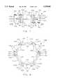
- FIG. 1illustrates a portion of a hybrid alternator in accordance with the present invention showing generally the structure thereof.
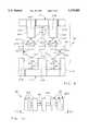
- FIG. 2illustrates a disassembled view of claw-pole members and magnet assembly in accordance with a first claw-pole member geometry with the curvature of illustrated features omitted for clarity.
- FIG. 3illustrates a permanent magnet assembly in accordance with the present invention.
- FIGS. 4-8show various views of a permanent magnet assembly and portions thereof for use with the first claw-pole geometry illustrated in FIG. 2.
- FIG. 9illustrates a disassembled view of claw-pole members and magnet assembly in accordance with a second claw-pole member geometry with the curvature of illustrated features omitted for clarity.
- FIGS. 10-11show various views of a permanent magnet assembly suitable for use with the second claw-pole geometry illustrated in FIG. 9.
- FIG. 12is a perspective illustration of a claw-pole member in accordance with the first geometry as illustrated in FIG. 2.
- FIG. 1one representative form of a rotor assembly for application in a hybrid generator and embodying the concepts of the present invention is designated by the numeral 10 in FIG. 1.
- the rotoris comprised of a shaft 11 that is supported for rotation by bearings (not shown) and coupled to a prime mover such as a motor vehicle engine via a pulley system and an accessory drive belt (also not shown).
- Rotor 10further comprises claw pole members 15 and 17 which are secured to shaft 11 to rotate therewith.
- a core 13is also secured to shaft 11 intermediate claw-pole members 15 and 17.
- Claw-pole members 15,17, core 13 and shaft 10are a magnetic material such as steel.
- core 13is illustrated as an individual component piece, however, it is to be understood that the core of rotor 10 may be an integral axial extension of one or both claw-pole members.
- field coil assembly 21which is comprised of an insulative spool 23 and field coil 24.
- Alternatives to this established core and spool designare known, including one alternative for achieving improved heat conduction from the coil windings to the core as disclosed in U.S. Pat. No. 4,588,915 to Gold et al., also assigned to the assignee of the present invention.
- the ends of field coil 24are coupled to respective slip rings 25 and 26, typically copper, via conductors 29 and 27 respectively.
- Slip rings 25,26 and conductors 29,27likewise are secured to rotate with shaft 11, the flux generating direct current being delivered to the field coil 24 by a pair of brushes (not shown) contacting the slip rings.
- Each claw-pole member 15,17is identical to the other, having respective hub sections 15A,17A and a plurality of respective pole fingers 15B,17B.
- the pole fingersextend axially from the hub sections bracketing the field coil assembly 21 and core 13 radially inwardly therefrom.
- the pole fingers of each claw-pole memberfurther are symmetrically spaced around the perimeter of the hub section and as assembled onto the shaft 11 interleave in a non-contacting spaced relationship with the pole fingers of the other claw-pole member.
- Permanent magnets 31are generally rectangularly shaped with substantially flat faces. Each permanent magnet 31 has a pair of opposing pole faces 31N and 31S corresponding to north and south magnetic polarities respectively. These pole faces engage respective side surfaces on pole fingers 15B and 17B. All pole fingers 15B have respective side surfaces 14A,14B engaged with similar pole surfaces, 31N in the illustration. Likewise, pole fingers 17B have respective side surfaces 16A,16B engaged with the other similar pole surfaces, 31S in the illustration. Therefore, all pole fingers 15B have a north magnetic polarity and all pole fingers 17B have south magnetic polarity.
- the front faces 31F of the permanent magnets 31are radially outward toward the stator and the back faces 31B of the permanent magnets 31 are radially inward toward the field coil assembly 21.
- the two end faces 31Eare at opposite axial ends of each magnet 31.
- FIG. 12a preferred geometry for a claw pole member is illustrated in a perspective view for clarity.
- FIG. 2provides a disassembled view of the two claw-pole members and permanent magnet assembly wherein the curvature of those features is omitted for clarity and the illustration therefore represents those features as appearing as if the structures were straightened out across the page.
- the number of pole fingers on each claw-pole memberequals six, and each pole finger is generally V-shaped. That is to say, each pole finger is wider at the proximal end at the hub sections 15A,17A and tapered narrower at the distal end extending away from the respective hub section.
- Each pole finger 15B and 17Bhas a pair of respective side surfaces 14A,14B and 16A,16B and a corresponding pair of support ledges 40A,40B and 41A,41B which are substantially normal to the respective side surfaces.
- Claw-pole members of such geometrymay be produced either by forming out of heavy gauge steel by compression molding with heavy piercing and forming equipment as is well known in the art or produced by forming out of compressed iron particles as taught, for example, in U.S. patent application Ser. No. 08/157,452 assigned to the assignee of the present invention.
- the spaces between the interleaved pole fingers 15B and 17Bdefine permanent magnet positions bounded by opposing respective side surfaces 14A,16B and 14B,16A. Furthermore, respective support ledges 40A,41B and 40B,41A further define these positions.
- the combination of the opposing side surfaces and corresponding support ledgesprovides a channel for the permanent magnets having radial and circumferential boundaries for containment of the magnets 31. Each channel is skewed on a diagonal with respect to axial alignment due to the characteristic V-shape of the claw-pole members; adjacent channels skewed in opposite diagonal directions and alternating channels being skewed in the same diagonal direction.
- a substantially ring-shaped carrier 50surrounds the field coil assembly 21.
- Permanent magnets 31are coupled to carrier 50 about the outside perimeter thereof by appropriate fastening means, for example adhesives.
- the permanent magnets 31are complementarily oriented and circumferentially spaced with respect to the permanent magnet channels so as to nest therein. Therefore, each magnet is skewed on a diagonal. Adjacent magnets are skewed in opposite diagonal directions and alternating magnets are skewed in the same diagonal direction.
- Carrier 50is preferably made from an appropriate plastic such as "ULTEM 2100" commercially available from General Electric.
- claw-pole member 15is first assembled to shaft 11 followed by core 13 and coil assembly 21, magnet assembly 60 is placed around the field coil assembly 21 and locates all of the plurality of permanent magnets 31 against respective side surfaces 14A,14B and support ledges 40A,40B of pole fingers 15. Thereafter, claw-pole member 17 is assembled to shaft 11, the side surfaces 16A,16B and support ledges 41A,41B contacting the pre-located permanent magnets 31 in the same fashion as side surfaces and support ledges of fingers 15B.
- magnet assembly 60is illustrated apart from other components of the rotor 10.
- Carrier 50again preferably is comprised of a suitable material to which the permanent magnets are secured in appropriate orientation.
- Pole faces 31N,31S, back and front faces 31B,31F and end faces 31Eare all illustrated and labeled.
- FIGS. 4-8illustrate with various views a preferred design of a magnet assembly 100 consistent with the concepts and advantages of the present invention. It is assumed that the claw-pole members are similar in as much as they are generally V-shaped and cooperate to define channels via side surfaces and support ledges.
- the carrier 110 in this embodimentcomprises two substantially ring-shaped carriers 110A,110B, each supporting one half of the total number of permanent magnets.
- the two carrier designis preferred for reasons of improved manufacturability as will become apparent in the following description.
- the basic orientation and circumferential placement of permanent magnets 131 in magnet assembly 100are seen to be the same as well they should be given that the assembly is providing for permanent magnet placement corresponding to like V-shaped claw-pole members.
- each permanent magnethas a modified shape for improved fastening to a respective substantially ring-shaped carrier.
- a first magnet assembly 100Acomprised of a first substantially ring-shaped carrier 110A and a plurality of first permanent magnets 131 is illustrated.
- the plurality of first permanent magnets 131are disposed in spaced relationship about the perimeter of carrier 110A. These permanent magnets correspond to a plurality of first alternating channel positions created by the cooperation of the two claw-pole members. As such, all of the magnets secured to carrier 110A are skewed in a first diagonal direction.
- a plurality of second permanent magnets 131are disposed about the perimeter of a second substantially ring-shaped carrier 110B and comprise a second magnet assembly 100B.
- first and second substantially ring-shaped carriersare shown stacked axially in FIG. 4 in the manner as they would be found assembled about the field coil assembly including appropriate circumferential spacing of the adjacent permanent magnets.
- first and second carrier membersmay be assembled individually in sequence about the field coil assembly or sub-assembled and placed about the field coil assembly in a single step.
- a preferred designprovides for continuous slots 125 formed around the end faces 131E and front and back faces 131F, 131B of the permanent magnets 131.
- Each slot 125provides a void for a band 126 of plastic therein, which band 126 is integral with the first carrier member 110A thereby cooperatively trapping and securing the permanent magnet.
- the plurality of first permanent magnets 131are insert molded to the first carrier member 110A using well known overmolding techniques.
- the slots 125 in the permanent magnets 131provide voids for material flow around the magnet, the band 126 formed therein being integral with the first carrier member 110A. While the immediately prior description has been provided with respect to the plurality of first permanent magnets and first carrier member 110A, it is to be understood that the description applies to the second magnet assembly 100B comprised of a plurality of second permanent magnets 131 and second carrier member 110B.
- a two carrier designis preferred for improved manufacturability of a magnet assembly.
- the skewing of adjacent magnets in opposite diagonal directionsbecomes problematic for simple insert mold designs particularly with respect to mold release. While it is possible to overcome the mold related obstacles associated with such geometries, a simpler mold design and release is possible with the geometries presented by permanent magnets skewed in the same diagonal direction.
- a two carrier designadvantageously provides for some relative movement therebetween the two sets of magnets such that normal tolerance variations and stack-ups in the carriers, magnets and claw pole members are taken up during assembly.
- FIGS. 9-11alternative geometries for rotor claw-pole members and corresponding alternative geometries for magnet assemblies are illustrated.
- the claw-pole geometryis characterized by side surfaces and support ledges running substantially axially to thereby define axial permanent magnet channels.
- FIG. 9provides a disassembled view of two claw-pole members and permanent magnet assembly wherein the curvature of those features is omitted for clarity and the illustration therefore represents those features as appearing as if the structures were straightened out across the page. It is apparent that the basic relationship between claw-pole members 215,217 is identical to that of a rotor assembly having claw-pole members with V-shaped pole fingers.
- pole fingers 215B,217B interleave and pairs of opposing adjacent side surfaces 214A,216B and 214B,216A and corresponding pairs of support ledges 240A,241B and 240B,241Adefine the permanent magnet positions.
- the combination of the opposing side surfaces and corresponding support ledgesprovides a channel for the permanent magnets having radial and circumferential boundaries for containment of the magnets 231. Each channel, however, is seen to be axially aligned.
- permanent magnet assembly 260is comprised of a plurality of permanent magnets 231 coupled to a substantially ring-shaped carrier 250 at the outer periphery thereof.
- the permanent magnet assembly 260is assembled about the field coil assembly in a fashion previously described.
- Permanent magnets 231are coupled to carrier 250 by appropriate fastening means and in an orientation complementary with respect to the permanent magnet channels so as to nest therein. Therefore, each magnet is aligned radially and circumferentially spaced.
- Such an orientation of permanent magnetslends the permanent magnet assembly to alternative manufacturing techniques.
- channeled permanent magnetsmay be employed in an overmold process to integrate the magnets and carrier.
- An advantage to the axial alignment of the magnets in the present embodimentis that a unitary permanent magnet assembly may be overmolded.
- the problems associated with the oppositely skewed magnets of prior examples with respect to mold releaseare not encountered with the alignment geometry of the present embodiment. Therefore, a two carrier magnet assembly is not desirable nor necessary with this alternate geometry. While figures are not provided for an overmolded magnet assembly having axially aligned permanent magnets, the figures so illustrating such overmolded structures with skewed magnets provide ample illustration readily adaptable by one having ordinary skill in the art.
- magnetically isotropic, unmagnetized but magnetizable, componentsit is preferable to secure magnetically isotropic, unmagnetized but magnetizable, components to the carrier and thereafter applying a magnetic field thereto to establish the desired magnetic properties including pole orientation.
- An advantage of the latter techniqueis that intended pole faces of each yet unmagnetized component are positionally interchangeable and not subject to pole face alignment error prior to securing to the carrier.
- An additional advantage in forestailing the magnetizationis the reduced opportunity for magnet surface contamination due to attracted steel scrap from intermediate machining processes or contaminated work areas.
- magnetization after the overmold processingreduces difficulties associated with setting up steel dies with magnetized insert stock including orientation problems and magnet damage due to the strong attractive forces.
- an alternativeis to utilize permanent magnets which, prior to securing to the carrier(s), have the desired magnetic properties, including pole orientation as described thereby reducing handling and processing after manufacture.
- FIGS. 9-11Such a structure illustrating the axial geometry is illustrated in FIGS. 9-11 although it is to be understood that the general geometries with respect to magnet skewing as illustrated in grouped FIGS. 5,6 and 7,8 likewise may be formed as a unitary structure.
- Such structuresmay be formed, for example, by compressing particles of rare earth-iron alloys into unmagnetized assemblies which are thereafter magnetized by exposing at least the magnet portions to a magnetic field of suitable direction and field strength to establish the desired magnetic properties including pole orientation. It is likely unavoidable that a portion of the carrier will become magnetized but is not likely to have significant negative impact upon overall machine performance. In fact, such ancillary magnetization of the carrier may improve the performance of the machine.
Landscapes
- Engineering & Computer Science (AREA)
- Power Engineering (AREA)
- Synchronous Machinery (AREA)
- Permanent Field Magnets Of Synchronous Machinery (AREA)
- Permanent Magnet Type Synchronous Machine (AREA)
Abstract
Description
Claims (5)
Priority Applications (3)
| Application Number | Priority Date | Filing Date | Title |
|---|---|---|---|
| US08/361,419US5578885A (en) | 1994-12-22 | 1994-12-22 | Rotor assembly for hybrid alternator |
| EP95203087AEP0718959A3 (en) | 1994-12-22 | 1995-11-13 | Rotor assembly for hybrid alternator |
| JP7331339AJPH08223882A (en) | 1994-12-22 | 1995-12-20 | Hybrid alternator rotor assembly |
Applications Claiming Priority (1)
| Application Number | Priority Date | Filing Date | Title |
|---|---|---|---|
| US08/361,419US5578885A (en) | 1994-12-22 | 1994-12-22 | Rotor assembly for hybrid alternator |
Publications (1)
| Publication Number | Publication Date |
|---|---|
| US5578885Atrue US5578885A (en) | 1996-11-26 |
Family
ID=23421975
Family Applications (1)
| Application Number | Title | Priority Date | Filing Date |
|---|---|---|---|
| US08/361,419Expired - LifetimeUS5578885A (en) | 1994-12-22 | 1994-12-22 | Rotor assembly for hybrid alternator |
Country Status (3)
| Country | Link |
|---|---|
| US (1) | US5578885A (en) |
| EP (1) | EP0718959A3 (en) |
| JP (1) | JPH08223882A (en) |
Cited By (32)
| Publication number | Priority date | Publication date | Assignee | Title |
|---|---|---|---|---|
| US5828155A (en)* | 1995-12-08 | 1998-10-27 | Mitsubishi Denki Kabushiki Kaisha | Alternating current generator |
| US5925964A (en)* | 1993-08-30 | 1999-07-20 | Denso Corporation | Rotor for a rotating electric machine |
| US5969459A (en)* | 1997-01-14 | 1999-10-19 | Denso Corporation | Rotary electric machine having Lundell type core |
| US5973435A (en)* | 1997-05-07 | 1999-10-26 | Denso Corporation | Rotary electric machine having auxiliary permanent magnets |
| US6011343A (en)* | 1997-03-21 | 2000-01-04 | Denso Corporation | Rotor of rotary machine having claw poles and auxiliary permanent magnets |
| US6013968A (en)* | 1998-01-26 | 2000-01-11 | Robert Bosch Gmbh | Synchronous machine, in particular generator for motor vehicle |
| US6013967A (en)* | 1998-01-26 | 2000-01-11 | Robert Bosch Gmbh | Synchronous machine, in particular generator for motor vehicle |
| US6104118A (en)* | 1998-03-05 | 2000-08-15 | Hitachi, Ltd. | Alternating current generator for use in vehicle |
| US6144138A (en)* | 1996-10-17 | 2000-11-07 | Robert Bosch Gmbh | Claw pole generator |
| US6150746A (en)* | 1998-01-26 | 2000-11-21 | Robert Bosch Gmbh | Synchronous electrical machine with U-shaped non-magnetic holder for permanent magnets |
| US6359366B1 (en) | 2000-05-09 | 2002-03-19 | Ford Global Technologies, Inc. | Hybrid permanent magnet/synchronous machines |
| US6486585B1 (en)* | 1999-04-30 | 2002-11-26 | Valeo Equipments Electriques Moteur | Alternator with interpolar magnets for a motor vehicle |
| US6661151B2 (en)* | 2000-11-06 | 2003-12-09 | Denso Corporation | Alternator for vehicles having permanent magnets in rotor |
| US6724116B1 (en) | 2002-12-20 | 2004-04-20 | Visteon Global Technologies, Inc. | Alternator permanent magnet rotor design |
| US20040080235A1 (en)* | 2002-10-29 | 2004-04-29 | Visteon Global Technologies, Inc. | High power permanent magnet hybrid alternator rotor |
| US20040135464A1 (en)* | 2002-11-01 | 2004-07-15 | Mitsubishi Denki Kabushiki Kaisha | Rotor of rotating electric machine |
| US20050057106A1 (en)* | 2002-12-10 | 2005-03-17 | Ballard Power Systems Corporation | Methods and systems for electric machines having windings |
| US6933654B1 (en)* | 2004-04-27 | 2005-08-23 | Mitsubishi Denki Kabushiki Kaisha | Rotor of rotating electric machine |
| US20070188044A1 (en)* | 2003-12-01 | 2007-08-16 | Mitsubishi Denki Kabushiki Kaisha | Dynamoelectric rotor |
| US20080197736A1 (en)* | 2007-02-15 | 2008-08-21 | Hamilton Sundstrand Corporation | Magnet retention system for permanent magnet motors and generators |
| US20080197730A1 (en)* | 2007-02-15 | 2008-08-21 | Hamilton Sundstrand Corporation | Nested variable field dynamoelectric machine |
| WO2008129328A1 (en) | 2007-04-23 | 2008-10-30 | National Oilwell Varco, L.P. | A rotor for a permanent magnet motor |
| US20090218901A1 (en)* | 2006-04-10 | 2009-09-03 | Valeo Equipements Electriques Moteur | Rotor for a rotary electrical machine comprising grooves for magnets |
| US20100026130A1 (en)* | 2008-07-29 | 2010-02-04 | Denso Corporation | Electric rotary machine for vehicle |
| US8283833B2 (en) | 2008-10-31 | 2012-10-09 | Denso Corporation | Rotor for electric rotary machine |
| US20130200740A1 (en)* | 2010-10-14 | 2013-08-08 | Lothar Schröder | Permanent magnet rotor for an electric motor |
| US20130278087A1 (en)* | 2012-04-20 | 2013-10-24 | Mohammad Kimiabeigi | Rotor arrangement and electromechanical transducer having non-parallel permanent magnets |
| US9577501B2 (en) | 2013-04-05 | 2017-02-21 | Remy Technologies, Llc | Claw pole rotor with cavity for minimizing flux leakage |
| US10326323B2 (en) | 2015-12-11 | 2019-06-18 | Whirlpool Corporation | Multi-component rotor for an electric motor of an appliance |
| US10693336B2 (en) | 2017-06-02 | 2020-06-23 | Whirlpool Corporation | Winding configuration electric motor |
| US10704180B2 (en) | 2016-09-22 | 2020-07-07 | Whirlpool Corporation | Reinforcing cap for a tub rear wall of an appliance |
| US11316417B2 (en)* | 2017-10-25 | 2022-04-26 | Seg Automotive Germany Gmbh | Rotor of a claw pole machine |
Families Citing this family (20)
| Publication number | Priority date | Publication date | Assignee | Title |
|---|---|---|---|---|
| JPH11127561A (en) | 1997-10-22 | 1999-05-11 | Denso Corp | Concurrent rotor/magnet for electric rotating machine and manufacture thereof |
| JP3541920B2 (en)* | 1997-10-27 | 2004-07-14 | 三菱電機株式会社 | Rotor of rotating electric machine and method of manufacturing the same |
| DE19806667A1 (en)* | 1998-02-18 | 1999-08-19 | Bosch Gmbh Robert | Synchronous machine, especially generator for car |
| FR2784249B1 (en)* | 1998-10-02 | 2000-12-22 | Valeo Equip Electr Moteur | MOTOR VEHICLE ALTERNATOR WITH PERMANENT MAGNETS |
| JP4300702B2 (en)* | 2000-10-25 | 2009-07-22 | 株式会社デンソー | AC generator field rotor |
| JP3743431B2 (en)* | 2002-04-26 | 2006-02-08 | 株式会社日立製作所 | Vehicle alternator and its rotor |
| US6674205B2 (en)* | 2002-05-07 | 2004-01-06 | General Motors Corporation | Auxiliary magnetizing winding for interior permanent magnet rotor magnetization |
| JP2004266965A (en)* | 2003-03-04 | 2004-09-24 | Mitsubishi Electric Corp | Rotating electric machine rotor |
| US7989084B2 (en) | 2007-05-09 | 2011-08-02 | Motor Excellence, Llc | Powdered metal manufacturing method and devices |
| WO2008141214A1 (en) | 2007-05-09 | 2008-11-20 | Motor Excellence, Llc. | Electrical output generating devices and driven electrical devices with reduced flux leakage using permanent magnet components, and methods of making and using the same |
| EP2124236A1 (en)* | 2008-05-22 | 2009-11-25 | Metalor Technologies International S.A. | Use of an electric contact material to blow an electric arc |
| JP4605275B2 (en)* | 2008-08-29 | 2011-01-05 | 株式会社デンソー | AC generator for vehicles |
| JP4743257B2 (en)* | 2008-10-31 | 2011-08-10 | 株式会社デンソー | Rotor for rotating electrical machine and method for manufacturing the same |
| JP2012507983A (en) | 2008-11-03 | 2012-03-29 | モーター エクセレンス, エルエルシー | Multiphase transverse and / or commutated flux system |
| US8395291B2 (en) | 2010-03-15 | 2013-03-12 | Electric Torque Machines, Inc. | Transverse and/or commutated flux systems for electric bicycles |
| EP2548288A1 (en) | 2010-03-15 | 2013-01-23 | Motor Excellence, LLC | Transverse and/or commutated flux systems configured to provide reduced flux leakage, hysteresis loss reduction, and phase matching |
| WO2011115634A1 (en) | 2010-03-15 | 2011-09-22 | Motor Excellence Llc | Transverse and/or commutated flux systems having phase offset |
| US8405275B2 (en) | 2010-11-17 | 2013-03-26 | Electric Torque Machines, Inc. | Transverse and/or commutated flux systems having segmented stator laminations |
| US8854171B2 (en) | 2010-11-17 | 2014-10-07 | Electric Torque Machines Inc. | Transverse and/or commutated flux system coil concepts |
| US8952590B2 (en) | 2010-11-17 | 2015-02-10 | Electric Torque Machines Inc | Transverse and/or commutated flux systems having laminated and powdered metal portions |
Citations (6)
| Publication number | Priority date | Publication date | Assignee | Title |
|---|---|---|---|---|
| US3230404A (en)* | 1961-10-10 | 1966-01-18 | Chrysler Corp | Damping means for claw tooth rotors |
| US3411027A (en)* | 1965-07-15 | 1968-11-12 | Siemens Ag | Permanent magnet excited electric machine |
| US4588915A (en)* | 1984-12-14 | 1986-05-13 | General Motors Corporation | Alternating current generator rotor |
| US4959577A (en)* | 1989-10-23 | 1990-09-25 | General Motors Corporation | Alternating current generator |
| US5382862A (en)* | 1992-07-20 | 1995-01-17 | General Motors Corporation | Alternating current generator rotor |
| US5483116A (en)* | 1993-08-30 | 1996-01-09 | Nippondenso Co., Ltd. | Rotor for a rotating electric machine |
Family Cites Families (5)
| Publication number | Priority date | Publication date | Assignee | Title |
|---|---|---|---|---|
| JP2785423B2 (en)* | 1990-03-13 | 1998-08-13 | 株式会社デンソー | Rotor of vehicle alternator and method of manufacturing the same |
| JP3117019B2 (en)* | 1990-10-26 | 2000-12-11 | 株式会社デンソー | Rotor of rotating electric machine for vehicles |
| JP2987938B2 (en)* | 1990-12-26 | 1999-12-06 | 株式会社デンソー | Brushless rotary electric machine for vehicles |
| JP2924184B2 (en)* | 1990-12-27 | 1999-07-26 | 株式会社デンソー | AC generator |
| JP3237217B2 (en)* | 1991-08-08 | 2001-12-10 | 株式会社デンソー | Vehicle alternator rotor |
- 1994
- 1994-12-22USUS08/361,419patent/US5578885A/ennot_activeExpired - Lifetime
- 1995
- 1995-11-13EPEP95203087Apatent/EP0718959A3/ennot_activeWithdrawn
- 1995-12-20JPJP7331339Apatent/JPH08223882A/enactivePending
Patent Citations (6)
| Publication number | Priority date | Publication date | Assignee | Title |
|---|---|---|---|---|
| US3230404A (en)* | 1961-10-10 | 1966-01-18 | Chrysler Corp | Damping means for claw tooth rotors |
| US3411027A (en)* | 1965-07-15 | 1968-11-12 | Siemens Ag | Permanent magnet excited electric machine |
| US4588915A (en)* | 1984-12-14 | 1986-05-13 | General Motors Corporation | Alternating current generator rotor |
| US4959577A (en)* | 1989-10-23 | 1990-09-25 | General Motors Corporation | Alternating current generator |
| US5382862A (en)* | 1992-07-20 | 1995-01-17 | General Motors Corporation | Alternating current generator rotor |
| US5483116A (en)* | 1993-08-30 | 1996-01-09 | Nippondenso Co., Ltd. | Rotor for a rotating electric machine |
Cited By (54)
| Publication number | Priority date | Publication date | Assignee | Title |
|---|---|---|---|---|
| US5925964A (en)* | 1993-08-30 | 1999-07-20 | Denso Corporation | Rotor for a rotating electric machine |
| US5828155A (en)* | 1995-12-08 | 1998-10-27 | Mitsubishi Denki Kabushiki Kaisha | Alternating current generator |
| US6144138A (en)* | 1996-10-17 | 2000-11-07 | Robert Bosch Gmbh | Claw pole generator |
| US5969459A (en)* | 1997-01-14 | 1999-10-19 | Denso Corporation | Rotary electric machine having Lundell type core |
| US6011343A (en)* | 1997-03-21 | 2000-01-04 | Denso Corporation | Rotor of rotary machine having claw poles and auxiliary permanent magnets |
| US5973435A (en)* | 1997-05-07 | 1999-10-26 | Denso Corporation | Rotary electric machine having auxiliary permanent magnets |
| US6013968A (en)* | 1998-01-26 | 2000-01-11 | Robert Bosch Gmbh | Synchronous machine, in particular generator for motor vehicle |
| US6013967A (en)* | 1998-01-26 | 2000-01-11 | Robert Bosch Gmbh | Synchronous machine, in particular generator for motor vehicle |
| US6150746A (en)* | 1998-01-26 | 2000-11-21 | Robert Bosch Gmbh | Synchronous electrical machine with U-shaped non-magnetic holder for permanent magnets |
| US6104118A (en)* | 1998-03-05 | 2000-08-15 | Hitachi, Ltd. | Alternating current generator for use in vehicle |
| US6486585B1 (en)* | 1999-04-30 | 2002-11-26 | Valeo Equipments Electriques Moteur | Alternator with interpolar magnets for a motor vehicle |
| US6359366B1 (en) | 2000-05-09 | 2002-03-19 | Ford Global Technologies, Inc. | Hybrid permanent magnet/synchronous machines |
| US6548931B2 (en) | 2000-05-09 | 2003-04-15 | Ballard Power Systems Corporation | Hybrid permanent magnet/synchronous machines |
| US6661151B2 (en)* | 2000-11-06 | 2003-12-09 | Denso Corporation | Alternator for vehicles having permanent magnets in rotor |
| US20040080235A1 (en)* | 2002-10-29 | 2004-04-29 | Visteon Global Technologies, Inc. | High power permanent magnet hybrid alternator rotor |
| US6744165B2 (en)* | 2002-10-29 | 2004-06-01 | Visteon Global Technologies, Inc. | High power permanent magnet hybrid alternator rotor |
| US20040135464A1 (en)* | 2002-11-01 | 2004-07-15 | Mitsubishi Denki Kabushiki Kaisha | Rotor of rotating electric machine |
| US6806616B2 (en)* | 2002-11-01 | 2004-10-19 | Mitsubishi Denki Kabushiki Kaisha | Rotor of rotating electric machine |
| US20050057106A1 (en)* | 2002-12-10 | 2005-03-17 | Ballard Power Systems Corporation | Methods and systems for electric machines having windings |
| US6724116B1 (en) | 2002-12-20 | 2004-04-20 | Visteon Global Technologies, Inc. | Alternator permanent magnet rotor design |
| US20070188044A1 (en)* | 2003-12-01 | 2007-08-16 | Mitsubishi Denki Kabushiki Kaisha | Dynamoelectric rotor |
| US7259489B2 (en)* | 2003-12-01 | 2007-08-21 | Mitsubishi Denki Kabushiki Kaisha | Dynamoelectric claw-shaped rotor with magnet retainer |
| US7345394B2 (en) | 2003-12-01 | 2008-03-18 | Mitsubishi Denki Kabushiki Kaisha | Dynamoelectric claw-shaped rotor with magnet retainer |
| US7368841B2 (en) | 2003-12-01 | 2008-05-06 | Mitsubishi Denki Kabushiki Kaisha | Dynamoelectric claw-shaped rotor with magnet retainer |
| US7417350B2 (en) | 2003-12-01 | 2008-08-26 | Mitsubishi Denki Kabushiki Kaisha | Dynamoelectric claw-shaped rotor with magnet retainer |
| US6933654B1 (en)* | 2004-04-27 | 2005-08-23 | Mitsubishi Denki Kabushiki Kaisha | Rotor of rotating electric machine |
| US20090218901A1 (en)* | 2006-04-10 | 2009-09-03 | Valeo Equipements Electriques Moteur | Rotor for a rotary electrical machine comprising grooves for magnets |
| US8191229B2 (en) | 2006-04-10 | 2012-06-05 | Valeo Equipements Electriques Moteur | Rotor for a rotary electrical machine comprising grooves for magnets |
| US8148873B2 (en)* | 2006-04-10 | 2012-04-03 | Valeo Equipements Electriques Moteur | Rotor for a rotary electrical machine comprising grooves for magnets |
| US20080197736A1 (en)* | 2007-02-15 | 2008-08-21 | Hamilton Sundstrand Corporation | Magnet retention system for permanent magnet motors and generators |
| US7642684B2 (en) | 2007-02-15 | 2010-01-05 | Hamilton Sunstrand Corporation | Nested variable field dynamoelectric machine |
| US7646124B2 (en) | 2007-02-15 | 2010-01-12 | Hamilton Sundstrand Corporation | Magnet retention system for permanent magnet motors and generators |
| US20080197730A1 (en)* | 2007-02-15 | 2008-08-21 | Hamilton Sundstrand Corporation | Nested variable field dynamoelectric machine |
| US7673380B2 (en) | 2007-04-23 | 2010-03-09 | Varco I/P, Inc. | Methods for making rotors for permanent magnet motors |
| WO2008129328A1 (en) | 2007-04-23 | 2008-10-30 | National Oilwell Varco, L.P. | A rotor for a permanent magnet motor |
| US20100026130A1 (en)* | 2008-07-29 | 2010-02-04 | Denso Corporation | Electric rotary machine for vehicle |
| US8810101B2 (en)* | 2008-07-29 | 2014-08-19 | Denso Corporation | Electric rotary machine having claw magnetic poles with flanges having centrifugal force resistance |
| US8283833B2 (en) | 2008-10-31 | 2012-10-09 | Denso Corporation | Rotor for electric rotary machine |
| US20130200740A1 (en)* | 2010-10-14 | 2013-08-08 | Lothar Schröder | Permanent magnet rotor for an electric motor |
| US9425659B2 (en)* | 2010-10-14 | 2016-08-23 | Continental Automotive Gmbh | Sheet metal holder for retaining permanent magnets |
| US20130278087A1 (en)* | 2012-04-20 | 2013-10-24 | Mohammad Kimiabeigi | Rotor arrangement and electromechanical transducer having non-parallel permanent magnets |
| US9419480B2 (en)* | 2012-04-20 | 2016-08-16 | Siemens Aktiengesellschaft | Rotor arrangement and electromechanical transducer having non-parallel permanent magnets |
| US9577501B2 (en) | 2013-04-05 | 2017-02-21 | Remy Technologies, Llc | Claw pole rotor with cavity for minimizing flux leakage |
| US10326323B2 (en) | 2015-12-11 | 2019-06-18 | Whirlpool Corporation | Multi-component rotor for an electric motor of an appliance |
| US10897167B2 (en) | 2015-12-11 | 2021-01-19 | Whirlpool Corporation | Multi-component rotor for an electric motor of an appliance |
| US11374448B2 (en) | 2015-12-11 | 2022-06-28 | Whirlpool Corporation | Multi-component rotor for an electric motor of an appliance |
| US11641138B2 (en) | 2015-12-11 | 2023-05-02 | Whirlpool Corporation | Multi-component rotor for an electric motor of an appliance |
| US11909265B2 (en) | 2015-12-11 | 2024-02-20 | Whirlpool Corporation | Multi-component rotor for an electric motor of an appliance |
| US10704180B2 (en) | 2016-09-22 | 2020-07-07 | Whirlpool Corporation | Reinforcing cap for a tub rear wall of an appliance |
| US11473231B2 (en) | 2016-09-22 | 2022-10-18 | Whirlpool Corporation | Reinforcing cap for a tub rear wall of an appliance |
| US12031260B2 (en) | 2016-09-22 | 2024-07-09 | Whirlpool Corporation | Reinforcing cap for a tub rear wall of an appliance |
| US10693336B2 (en) | 2017-06-02 | 2020-06-23 | Whirlpool Corporation | Winding configuration electric motor |
| US11482901B2 (en) | 2017-06-02 | 2022-10-25 | Whirlpool Corporation | Winding configuration electric motor |
| US11316417B2 (en)* | 2017-10-25 | 2022-04-26 | Seg Automotive Germany Gmbh | Rotor of a claw pole machine |
Also Published As
| Publication number | Publication date |
|---|---|
| EP0718959A2 (en) | 1996-06-26 |
| JPH08223882A (en) | 1996-08-30 |
| EP0718959A3 (en) | 1998-03-04 |
Similar Documents
| Publication | Publication Date | Title |
|---|---|---|
| US5578885A (en) | Rotor assembly for hybrid alternator | |
| EP2076954B1 (en) | Motor with permanent magnets and method of manufacturing; power tool with same | |
| US5747913A (en) | Rotor for hybrid generator having improved magnet retention | |
| US6601287B2 (en) | Motor including embedded permanent-magnet rotor and method for making same | |
| US7088024B2 (en) | Field assembly for a motor and method of making same | |
| US5554900A (en) | Motor including embedded permanent-magnet rotor | |
| US4625392A (en) | Method of manufacturing a molded rotatable assembly for dynamoelectric machines | |
| US20040113511A1 (en) | Component for the rotor or stator of an electrical machine | |
| US20190109525A1 (en) | Rotor of Rotating Electric Machine and Manufacturing Method of the Same | |
| JP2003513597A (en) | Electric machine | |
| US6785951B2 (en) | Rotor assembly and method of making | |
| US20110278966A1 (en) | Motor With Overmolded Permanent Magnets | |
| JP2006109573A (en) | Rotating electric machine for vehicle and manufacturing method thereof | |
| EP1237252B1 (en) | Magnet assembly for a motor and method of making same | |
| JP3928297B2 (en) | Electric motor and manufacturing method thereof | |
| US20110298313A1 (en) | Motor With Permanent Magnets and Method of Manufacturing Power Tool With Same | |
| US4532448A (en) | Flux director, tooth shield | |
| CN112655136B (en) | Enhanced geometry of permanent magnet claw-shaped pole segments | |
| JP4482900B2 (en) | Axial gap type motor | |
| US20220329120A1 (en) | Active part of an electric machine, electric machine, and method for producing a pre-mounted assembly for the active part | |
| SU1350759A1 (en) | Rotor of electric machine | |
| CZ293220B6 (en) | Electric motor stator having permanent magnets | |
| CN120613860A (en) | Armature and method for manufacturing armature | |
| JPS61150650A (en) | Motor | |
| JPS59178942A (en) | Assembling method of brushless motor |
Legal Events
| Date | Code | Title | Description |
|---|---|---|---|
| AS | Assignment | Owner name:GENERAL MOTORS CORPORATION, MICHIGAN Free format text:ASSIGNMENT OF ASSIGNORS INTEREST;ASSIGNORS:ALFORD, STEPHEN ALAN;RAUSCH, RICHARD ALLEN;SHIRK, GILBERT EDWARD;REEL/FRAME:007329/0723;SIGNING DATES FROM 19950127 TO 19950128 | |
| STCF | Information on status: patent grant | Free format text:PATENTED CASE | |
| FPAY | Fee payment | Year of fee payment:4 | |
| AS | Assignment | Owner name:DELPHI TECHNOLOGIES, INC., MICHIGAN Free format text:ASSIGNMENT OF ASSIGNORS INTEREST;ASSIGNOR:GENERAL MOTORS CORPORATION;REEL/FRAME:012745/0724 Effective date:20020212 | |
| FPAY | Fee payment | Year of fee payment:8 | |
| AS | Assignment | Owner name:DEUTSCHE BANK NATIONAL TRUST COMANY, AS COLLATERAL Free format text:SECURITY AGREEMENT;ASSIGNOR:DELCO REMY INTERNATIONAL, INC.;REEL/FRAME:015377/0076 Effective date:20040423 | |
| FPAY | Fee payment | Year of fee payment:12 | |
| AS | Assignment | Owner name:REMY TECHNOLOGIES, LLC, INDIANA Free format text:ASSIGNMENT OF ASSIGNORS INTEREST;ASSIGNOR:DELPHI TECHNOLOGIES, INC.;REEL/FRAME:025114/0809 Effective date:20101005 | |
| AS | Assignment | Owner name:BANK OF AMERICA, N.A., AS ADMINISTRATIVE AGENT, NO Free format text:GRANT OF PATENT SECURITY INTEREST;ASSIGNOR:REMY TECHNOLOGIES, L.L.C.;REEL/FRAME:025521/0387 Effective date:20101217 | |
| AS | Assignment | Owner name:WELLS FARGO CAPITAL FINANCE, LLC, AS AGENT, ILLINO Free format text:SECURITY AGREEMENT;ASSIGNORS:REMY TECHNOLOGIES, L.L.C.;REMY POWER PRODUCTS, LLC;REEL/FRAME:025525/0186 Effective date:20101217 | |
| AS | Assignment | Owner name:REMY INC. (F/K/A DELCO REMY AMERICA INC.), INDIANA Free format text:RELEASE BY SECURED PARTY;ASSIGNOR:DEUTSCHE BANK NATIONAL TRUST COMPANY;REEL/FRAME:037075/0029 Effective date:20080428 Owner name:REMY INTERNATIONAL INC. (F/K/A DELCO REMY INTERNAT Free format text:RELEASE BY SECURED PARTY;ASSIGNOR:DEUTSCHE BANK NATIONAL TRUST COMPANY;REEL/FRAME:037075/0029 Effective date:20080428 Owner name:REMY TECHNOLOGIES, L.L.C., INDIANA Free format text:RELEASE BY SECURED PARTY;ASSIGNOR:DEUTSCHE BANK NATIONAL TRUST COMPANY;REEL/FRAME:037075/0029 Effective date:20080428 | |
| AS | Assignment | Owner name:REMY TECHNOLOGIES, L.L.C., INDIANA Free format text:RELEASE OF SECURITY INTEREST IN PATENTS PREVIOUSLY RECORDED AT REEL/FRAME 025521/0387;ASSIGNOR:BANK OF AMERICA, N.A.;REEL/FRAME:037101/0125 Effective date:20151110 Owner name:REMY TECHNOLOGIES, L.L.C., INDIANA Free format text:RELEASE OF SECURITY INTEREST IN PATENTS PREVIOUSLY RECORDED AT REEL/FRAME 025525/0186;ASSIGNOR:WELLS FARGO CAPITAL FINANCE, L.L.C.;REEL/FRAME:037108/0618 Effective date:20151110 Owner name:REMY POWER PRODUCTS, L.L.C., INDIANA Free format text:RELEASE OF SECURITY INTEREST IN PATENTS PREVIOUSLY RECORDED AT REEL/FRAME 025525/0186;ASSIGNOR:WELLS FARGO CAPITAL FINANCE, L.L.C.;REEL/FRAME:037108/0618 Effective date:20151110 |