US5578818A - LED point scanning system - Google Patents
LED point scanning systemDownload PDFInfo
- Publication number
- US5578818A US5578818AUS08/438,416US43841695AUS5578818AUS 5578818 AUS5578818 AUS 5578818AUS 43841695 AUS43841695 AUS 43841695AUS 5578818 AUS5578818 AUS 5578818A
- Authority
- US
- United States
- Prior art keywords
- sample
- returning
- scan head
- illumination
- collimated
- Prior art date
- Legal status (The legal status is an assumption and is not a legal conclusion. Google has not performed a legal analysis and makes no representation as to the accuracy of the status listed.)
- Expired - Lifetime
Links
- 238000005286illuminationMethods0.000claims38
- 230000005855radiationEffects0.000claims16
- 238000001514detection methodMethods0.000claims15
- 239000000835fiberSubstances0.000claims7
- 239000013307optical fiberSubstances0.000claims7
- 239000007787solidSubstances0.000claims3
- 238000003384imaging methodMethods0.000claims2
- 230000003287optical effectEffects0.000claims2
Images


Classifications
- G—PHYSICS
- G01—MEASURING; TESTING
- G01N—INVESTIGATING OR ANALYSING MATERIALS BY DETERMINING THEIR CHEMICAL OR PHYSICAL PROPERTIES
- G01N21/00—Investigating or analysing materials by the use of optical means, i.e. using sub-millimetre waves, infrared, visible or ultraviolet light
- G01N21/62—Systems in which the material investigated is excited whereby it emits light or causes a change in wavelength of the incident light
- G01N21/63—Systems in which the material investigated is excited whereby it emits light or causes a change in wavelength of the incident light optically excited
- G01N21/64—Fluorescence; Phosphorescence
- G01N21/645—Specially adapted constructive features of fluorimeters
- G01N21/6452—Individual samples arranged in a regular 2D-array, e.g. multiwell plates
Definitions
- This inventionrelates to moving head optical scanners for stimulating a target and for reading the fluorescent and reflective signal radiation that is returned from the target.
- Moving head optical scanners for stimulation of target samples and for reading of the fluorescent and reflective signal radiation that emerges from the samplesare used in many experimental formats.
- many existing scannersare limited with respect to scan speed, resolution, and field size because of their numerous components and the high mass of their optical assemblies. It is desirable to increase scan speed without compromising resolution in order to scan many samples in a short period of time.
- the movement of a light beam to effect scanning in most optical scannersis generally accomplished via galvanometer scanning mechanisms or rotating polygonal mirrors. These devices are best suited for small fields when the same objective is utilized for both excitation and collection or large fields when a separate light collector is used, usually a nonimaging optic. When it is beneficial to have coaxial excitation and detection, scanning of large fields is best accomplished by moving the scan head or by moving the sample. The lens is used only for single point illumination and collection along the center of the optical axis.
- a stationary light sourcesuch as a xenon lamp or a gas laser
- an optical fiberto deliver the excitation light to the scan head
- a compact laser diodeif the appropriate wavelength is available.
- Laser diodesare generally available at wavelengths of 635 nm and greater. Both alternatives can be complex and expensive.
- the above objecthas been achieved with an optical scanner having a Light Emitting Diode (LED) light source for point imaging of target samples.
- the LEDprovides a compact, inexpensive, and lightweight light source and thus can be housed directly within a movable scan head.
- the LEDprovides an illumination beam that is focused into a pinhole aperture of a spatial filter, then collimated and focused onto a spot on the sample.
- the pinholedefines the necessary resolution of the illumination beam and functions as an apparent point light source for forming the spot to be used to scan the sample.
- an optical fibermay be substituted for the spatial filter in the illumination beam path to restrict the beam to a point light source.
- an optical fiber in the illumination beam pathallows the LED to be removed from the scan head, if desired. The scan head is moved across the sample along one or two axes.
- Fluorescence and reflective signal radiation returned from the illuminated spot on the samplemay be gathered through the scan head and detected by a small detector placed directly on the scan head.
- a focusing lens and a spatial filter with a pinhole aperturemay be provided in the return path leading to the detector, in order to enhance the detection of the returned signal radiation.
- an optical fibermay be used in the returning beam path to receive the fluorescence and reflection signals and to transmit them to the detector on the scan head or to a remote stationary detector.
- the returning light beam from the target sampleis directed to the detection means via a wavelength discrimination filter, in the case of fluorescence detection, or by a partial reflection filter, for detection of reflection signals.
- the information regarding the returning light pathis digitized and displayed or saved in a memory for future analysis.
- the present inventionhas the advantage of allowing a light source for an optical scanner to be placed directly on the movable scan head. Since the light source is itself lightweight, compact, inexpensive, and powerful, it is well-suited to a rapid scanning system design.
- the point imaging of the present inventionprovides precise, location-specific information regarding the target sample. Additionally, it provides a collimated beam in the returning beam path which allows for the use of high performance interference filters for optimum illumination beam rejection.
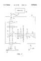
- FIG. 1is a plan view of a first embodiment of the LED point scanning system of the present invention.
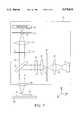
- FIG. 2is a plan view of a second embodiment of the LED point scanning system of the present invention.
- FIG. 3depicts the use of a wavelength discrimination filter in the optical path of the present invention.
- FIG. 4depicts the use of a partial reflection filter in the optical path of the present invention.
- FIG. 5depicts a variation of the embodiment of FIG. 2, having a spatial filter in the returning light beam path.
- FIG. 6depicts a third embodiment of the LED point scanning system of the present invention.
- FIG. 7depicts a variation of the embodiment of FIG. 6, wherein the LED light source is removed from the scan head.
- an LED light source 12 of scan head 20provides an illumination beam 11 which is gathered by a first focusing lens 14 and then focused onto a spatial filter 30.
- the spatial filter 30is provided with a pinhole 15.
- Illumination beam 11is focused into pinhole 15 by first focusing lens 14 which is optimized to focus the illumination beam 11 with greatest possible energy density.
- Pinhole 15is positioned at this point and effectively creates a point light source for the illumination optical path.
- the collimated illumination beamthen passes through a first filter 18 which defines the illumination wavelength band and then impinges upon beam splitter 24 which reflects at least a portion of the collimated illumination beam and directs it toward objective lens 32.
- Objective lens 32then focuses the received portion of the collimated illumination beam onto sample 10 at a spot 17.
- the numerical aperture of collimating lens 16is equal to the numerical aperture of objective lens 32. This helps to provide the optimum energy density at the scan spot 17.
- Sample 10is shown supported by a stage 38.
- the incident beam 11may cause reflective or fluorescent signal radiation to be returned from the illuminated spot 17 of sample 10.
- the signal radiationis collected by objective lens 32 and collimated into a returning light beam 13. At least a portion of returning light beam 13 passes through beam splitter 24 and then through second filter 22. After passing through second filter 22, the portion of the returning light beam 13 is then received by second focusing lens 34 and focused to a point 19 on the receiving section of a detection means.
- the scan head 20contains the LED 12 and the receiving section of the detection means. Scanning of the sample may be effected by moving the scan head 20 along a first axis to illuminate a plurality of spots along a scan line on the sample, e.g. the X-axis in FIG. 1, and then moving the stage 38, upon which the sample is supported, in a perpendicular axis. Alternatively, two-dimensional scan head movement may be desired and thus scanning may occur first along one axis and then along a second axis, perpendicular to the first axis, e.g. along the X- and Y-axes of FIG. 1. Thus, the Y-axis scan would cause illumination of spots on a plurality of parallel scan lines.
- the scan head 20may be moved by a belt and pulley system, or other mechanical means.
- the LED point scanning system of the present inventioncauses sequential point-by-point illumination of the target area of the sample. Collection and detection of the illuminated spots causes a point-by-point imaging of that target area.
- the radiation collected from the sampleis fluorescent, scattered, or reflected light from the illuminated spot on the sample.
- the signals received from each illuminated spotmay be digitized, stored and mapped to a specific address corresponding to each spot. This mapping occurs in a computer memory or processor and is carried out for display purposes or for other analysis, such as data logging and statistical analysis.
- the proximity of the spots that are scanned in the point imaging systemmay be adjusted to correspond to the desired resolution of the analysis, e.g. contiguous or overlapping spots generally improve the clarity of the display.
- FIG. 1depicts a first embodiment of the optical system of the present invention.
- the returning light beam 13is focused onto a spot 19, indicative of the point image of illuminated spot 17, by second focusing lens 34.
- the spot 19is positioned at a first end of an optical fiber 36.
- the first end of optical fiber 36is situated on the scan head 20.
- the second end of optical fiber 36is connected to a stationary detector 40, which is positioned off the scan head 20.
- the point image of the illuminated spot on the sampleis received by the optical fiber 36 and then is transmitted to the detector 40 for future analysis, e.g. by display of digitized data, as described above.
- FIG. 2illustrating a second embodiment of the present invention
- the illumination beam path for the light incident upon the sampleis the same as that shown in FIG. 1.
- the collection and detection along the returning beam pathis also the same as in FIG. 1, with the exception that the returning light beam 13 is focused by second focusing lens 34 to a spot 19 which is directly received on the window of detector 42.
- Second focusing lens 34may be omitted if the window of detector 42 is sufficiently large, however.
- Spot 19is indicative of the point image of illuminated spot 17.
- Detector 42is a small detector, such as a small photomultiplier tube or a solid state detector, and is lightweight and compact so that it may be placed directly on scan head 20, as seen in FIG. 2. As with the embodiment of FIG. 1, the scan head 20 may move along one or two axes.
- FIGS. 3 and 4depict different types of beam splitters, and are examples of beam splitter 24 of the first and second embodiments.
- a wavelength discrimination filter 26such as a dichroic beam splitter, is placed in the path of the incident and returning light beams. Wavelength discrimination filter 26 is well-suited to fluorescence applications.
- Incoming illumination beam 11 of FIG. 3is at an excitation wavelength ⁇ 1 .
- Illumination beam 11is redirected by wavelength discrimination filter 26 and is made to impinge upon sample 10.
- Returning beam 13is of a different wavelength, ⁇ 2 , than the wavelength of illumination beam 11, as is the case in fluorescence applications.
- Returning beam 13is transmitted through wavelength discrimination filter 26 and then on toward the detector as in FIGS. 1 and 2.
- wavelength discrimination filter 26is designed to reflect light of ⁇ 1 and to transmit light of ⁇ 2 .
- FIG. 4shows the use of a different beam splitter than in FIG. 3.
- Partial reflection filter 28is placed within the optical paths of the illumination and returning beams, 11 and 13 respectively. Partial reflection filter 28 is best-suited for applications requiring analysis of light reflected from samples. Illumination beam 11, having wavelength ⁇ 1 , impinges upon partial reflection filter 28, which typically has 50% reflection capabilities. A first portion 11a of illumination beam 11 is reflected by partial reflection filter 28 and redirected toward sample 10. A second portion 11b of illumination beam 11 is transmitted through partial reflection filter 28 and is unused in the optical system of the present invention. Reflective signal photons from sample 10, which form returning beam 13, have the same wavelength ⁇ 1 as does illumination beam 11.
- Returning beam 13impinges upon partial reflection filter 28 and a first portion 13a is transmitted through filter 28 and directed on toward a detector.
- a second portion 13bis reflected by partial reflection filter 28 and redirected back toward LED 12 along the path taken by the incoming illumination beam 11. This second portion 13b of returning beam 13 is unused for detection purposes in the optical system of the present invention.
- wavelength discrimination filter 26or partial reflection filter 28 may be used depending upon the desired application. Because the returning beam 13 is of the same wavelength as the illumination beam 11 in reflection scanning, a wavelength discrimination filter is not the preferred method of splitting the optical paths for reflection applications. Similarly, when the illumination beam 11 and the returning beam 13 are of different wavelengths, as in fluorescence scanning, a partial reflection filter is not the preferred method of directing the beam as the use of such a filter results in unused portions of the beams.
- focusing lens 34need not be in the returning light beam path, but rather its use is dependent upon the type of detection means utilized.
- Another element that may be helpful in the return pathis a second spatial filter 45 having pinhole aperture 21, as seen in FIG. 5.
- the returning light beam 13is focused by focusing lens 34 into pinhole aperture 21, thus limiting the amount of scattered light collected.
- the restriction of returning beam 13 within pinhole 21is equivalent to spot 19 of FIG. 2.
- Detector 42may then be positioned behind the detection spatial filter 45 in a spaced-apart format, as shown, or it may adjoin spatial filter 45.
- the addition of spatial filter 45 to the returning light beam patheffectively creates a classic confocal system which may be desired for some applications.
- illumination spatial filter 30may be useful.
- an optical fibermay be used in place of spatial filter 45 to restrict the returning light beam in a manner analogous to fiber 44 of FIG. 6, discussed below, and to transmit the returning light beam toward the detector.
- FIG. 6illustrates an alternate embodiment of the present invention.
- the excitation spatial filter 30, which serves to narrow the illumination beam 11 to a point source,has been replaced by an optical fiber 44.
- the placement of first focusing lens 14 and collimating lens 16has also been altered, so that the focal points of these two lenses do not coincide, as in FIG. 1, but instead are spaced apart, with fiber 44 between them.
- the focal point of lens 14coincides with an entrance end of fiber 44 and the focal point of lens 16 coincides with an exit end of fiber 44.
- the illumination beam 11passes through lens 14, is focused into fiber 44 and transmitted through fiber 44, and is then received and collimated by lens 16.
- Optical fiber 44effectively acts as a spatial filter in the illumination path because it restricts the beam and creates a point source, which is advantageous in the LED point scanning system of the present invention.
- this embodimenthas been illustrated in FIG. 6 as a variation of the embodiment in FIG. 1, with respect to the returning beam path, it may also be described as a variation of the FIG. 2 or FIG. 5 embodiments.
- optical fiber 44may be utilized in the illumination path where the specifics of the returning light beam detection optics do not include an optical fiber, as in fiber 36, leading to a remote stationary detector, as in detector 40, but rather include a small detector mounted on the scan head.
- FIG. 7illustrates this variation, wherein LED 12 and lens 14 are in a remote stationary location, and optical fiber 44 receives and transmits the illumination beam from this source to the optics of movable scan head 20.
- the specifics of the returning light beam opticsmay vary from those shown in FIG. 7.
- the collimation of segments of both the illumination beam 11 and the returning beam 13is effected in order to best use the beam splitter and the filters in the optical paths, which work best at given angles of incidence.
- Spatial filter 30 having pinhole 15is used in the present invention because LED 12, an incoherent light source, serves as the illumination source of the point scanning system.
- the focal spot size of an incoherent light sourceis limited by the filament or chip size of the LED.
- the pinholeis typically smaller than the limited spot size and therefore provides higher scan resolution.
- a laser diode light sourcewhich would not require a limiting pinhole, is another small and lightweight light source.
- laser diodesare more expensive than LEDs, and are generally limited to very few wavelengths.
- the LED point scanning system of the present inventionmay be used in a wide variety of situations, such as fluorescent imaging of electrophoretic gels, blots, and membranes, tissue sections and other biological samples, reading of storage phosphor screens, and reflective imaging.
- the scan headmay be outfitted with the most effective type of beam splitter and the appropriate detection means.
- the present inventionprovides an inexpensive, versatile point scanner for rapid imaging of samples.
Landscapes
- Health & Medical Sciences (AREA)
- Nuclear Medicine, Radiotherapy & Molecular Imaging (AREA)
- Physics & Mathematics (AREA)
- Life Sciences & Earth Sciences (AREA)
- Chemical & Material Sciences (AREA)
- Analytical Chemistry (AREA)
- Biochemistry (AREA)
- General Health & Medical Sciences (AREA)
- General Physics & Mathematics (AREA)
- Immunology (AREA)
- Pathology (AREA)
- Investigating, Analyzing Materials By Fluorescence Or Luminescence (AREA)
- Microscoopes, Condenser (AREA)
- Photometry And Measurement Of Optical Pulse Characteristics (AREA)
- Mechanical Optical Scanning Systems (AREA)
- Investigating Or Analysing Materials By Optical Means (AREA)
Abstract
Description
Claims (34)
Priority Applications (4)
| Application Number | Priority Date | Filing Date | Title |
|---|---|---|---|
| US08/438,416US5578818A (en) | 1995-05-10 | 1995-05-10 | LED point scanning system |
| JP8534068AJPH10504916A (en) | 1995-05-10 | 1996-04-09 | LED point scanning system |
| PCT/US1996/005120WO1996036062A1 (en) | 1995-05-10 | 1996-04-09 | Led point scanning system |
| EP96911747AEP0770262A4 (en) | 1995-05-10 | 1996-04-09 | Led point scanning system |
Applications Claiming Priority (1)
| Application Number | Priority Date | Filing Date | Title |
|---|---|---|---|
| US08/438,416US5578818A (en) | 1995-05-10 | 1995-05-10 | LED point scanning system |
Publications (1)
| Publication Number | Publication Date |
|---|---|
| US5578818Atrue US5578818A (en) | 1996-11-26 |
Family
ID=23740573
Family Applications (1)
| Application Number | Title | Priority Date | Filing Date |
|---|---|---|---|
| US08/438,416Expired - LifetimeUS5578818A (en) | 1995-05-10 | 1995-05-10 | LED point scanning system |
Country Status (4)
| Country | Link |
|---|---|
| US (1) | US5578818A (en) |
| EP (1) | EP0770262A4 (en) |
| JP (1) | JPH10504916A (en) |
| WO (1) | WO1996036062A1 (en) |
Cited By (101)
| Publication number | Priority date | Publication date | Assignee | Title |
|---|---|---|---|---|
| US5729348A (en)* | 1996-08-21 | 1998-03-17 | Agfa Division, Bayer Corporation | Fluorescence dot area meter |
| WO1998048262A1 (en)* | 1997-04-23 | 1998-10-29 | Packard Instrument Company, Inc. | Measurement of fluorescence |
| EP0884582A1 (en)* | 1997-06-10 | 1998-12-16 | Bayer Corporation | Fluorescence dot area meter. |
| US5895915A (en)* | 1997-07-24 | 1999-04-20 | General Scanning, Inc. | Bi-directional scanning system with a pixel clock system |
| US5929453A (en)* | 1997-06-03 | 1999-07-27 | The United States Of America As Represented By The Secretary Of The Navy | Underwater spectroscopic detector |
| US5929985A (en)* | 1997-03-18 | 1999-07-27 | Sandia Corporation | Multispectral imaging probe |
| US6005965A (en)* | 1997-04-07 | 1999-12-21 | Komatsu Ltd. | Inspection apparatus for semiconductor packages |
| US6043506A (en)* | 1997-08-13 | 2000-03-28 | Bio-Rad Laboratories, Inc. | Multi parameter scanner |
| US6068753A (en)* | 1996-05-06 | 2000-05-30 | Helena Laboratories Corporation | Automatic electrophoresis apparatus with fluorescent and visible scanning |
| US6108082A (en)* | 1998-01-07 | 2000-08-22 | Bio-Rad Laboratories | Spectral imaging apparatus and methodology |
| US6184534B1 (en)* | 1998-08-04 | 2001-02-06 | Eastman Kodak Company | Method of pulsing light emitting diodes for reading fluorescent indicia, data reader, and system |
| US6185030B1 (en) | 1998-03-20 | 2001-02-06 | James W. Overbeck | Wide field of view and high speed scanning microscopy |
| US6201639B1 (en) | 1998-03-20 | 2001-03-13 | James W. Overbeck | Wide field of view and high speed scanning microscopy |
| WO2002001194A1 (en)* | 2000-06-25 | 2002-01-03 | Affymetrix, Inc. | Optically active substrates |
| US6355938B1 (en) | 1998-11-25 | 2002-03-12 | Phormax Corporation | Phosphor screen scanning systems |
| US6388807B1 (en) | 1999-10-12 | 2002-05-14 | Leica Microsystems Heidelberg Gmbh | Confocal laser scanning microscope |
| US20030021020A1 (en)* | 2001-07-30 | 2003-01-30 | Leica Microsystems Heidelberg Gmbh | Method for scanning microscopy; and scanning microscope |
| US20030063851A1 (en)* | 2001-09-27 | 2003-04-03 | Bio-Rad Laboratories, Inc. | Biochemical assay detection in a liquid receptacle using a fiber optic exciter |
| US20030230728A1 (en)* | 2002-06-13 | 2003-12-18 | Zhengshan Dai | Multiwavelength transilluminator for absorbance and fluorescence detection using light emitting diodes |
| US6694356B1 (en) | 1998-09-11 | 2004-02-17 | L.V. Partner, L.P. | Remote control having an optical indicia reader |
| US6754414B2 (en) | 2001-09-27 | 2004-06-22 | Bio-Rad Laboratories, Inc. | Imaging of microarrays using fiber optic exciter |
| US6754698B1 (en) | 1998-09-11 | 2004-06-22 | L. V. Partners, L.P. | Method and apparatus for accessing a remote location with an optical reader having a dedicated memory system |
| US20040224421A1 (en)* | 2000-06-15 | 2004-11-11 | Deweerd Herman | Bi-directional scanning method |
| US6823388B1 (en) | 1998-09-11 | 2004-11-23 | L.V. Parners, L.P. | Method and apparatus for accessing a remote location with an optical reader having a programmable memory system |
| US20050012057A1 (en)* | 2003-05-08 | 2005-01-20 | Alara, Inc. | Method and apparatus for radiation image erasure |
| US6860424B1 (en) | 1998-09-11 | 2005-03-01 | L.V. Partners, L.P. | Optical reader and use |
| US20050206717A1 (en)* | 2004-03-19 | 2005-09-22 | Boyatt Richard G Iii | Collimation assembly for adjusting laser light sources in a multi-beamed laser scanning unit |
| US20050225764A1 (en)* | 2002-04-24 | 2005-10-13 | Tito Bacarese-Hamilton | Device and method for detecting fluorescence comprising a light emitting diode as excitation source |
| US20070007449A1 (en)* | 2005-06-23 | 2007-01-11 | Gfg Gesellschaft Fuer Geraetebau Mbh | Optical analysis device |
| US20070059754A1 (en)* | 2003-05-08 | 2007-03-15 | Bio-Rad Laboratories, Inc. | Systems and methods for fluorescence detection with a movable detection module |
| US20070065074A1 (en)* | 2001-09-27 | 2007-03-22 | Bio-Rad Laboratories, Inc. A Corporation Of The State Of Delaware | Biochemical assay detection using a fiber optic exciter |
| US20070106816A1 (en)* | 1998-09-11 | 2007-05-10 | Lv Partners, Lp | Method and apparatus for utilizing an existing product code to issue a match to a predetermined location on a global network |
| US20070114362A1 (en)* | 2005-11-23 | 2007-05-24 | Illumina, Inc. | Confocal imaging methods and apparatus |
| US20080117518A1 (en)* | 2006-11-21 | 2008-05-22 | Mark Wang | Microarray line scanning method and system |
| US20080117425A1 (en)* | 2006-11-21 | 2008-05-22 | Robert Kain | Hexagonal site line scanning method and system |
| US20080160601A1 (en)* | 2006-03-24 | 2008-07-03 | Kalyan Handique | Heater Unit for Microfluidic Diagnostic System |
| US20080188725A1 (en)* | 2007-02-06 | 2008-08-07 | Markle David R | Optical systems and methods for ratiometric measurement of blood glucose concentration |
| US7523161B2 (en) | 1998-09-11 | 2009-04-21 | Rpx-Lv Acquisition Llc | Control of software interface with information input to access window |
| US7536478B2 (en) | 1998-09-11 | 2009-05-19 | Rpx-Lv Acquisition Llc | Method and apparatus for opening and launching a web browser in response to an audible signal |
| US7548988B2 (en) | 1998-09-11 | 2009-06-16 | Rpx-Lv Acquisition Llc | Software downloading using a television broadcast channel |
| US20090236541A1 (en)* | 2008-03-24 | 2009-09-24 | General Electric Company | System and Methods for Optical Imaging |
| US7636788B2 (en) | 1998-09-11 | 2009-12-22 | Rpx-Lv Acquisition Llc | Method and apparatus for matching a user's use profile in commerce with a broadcast |
| US7739353B2 (en) | 1998-09-11 | 2010-06-15 | Rpx-Lv Acquisition Llc | Launching a web site using a personal device |
| US7819316B2 (en) | 1998-09-11 | 2010-10-26 | Lv Partners, L.P. | Portable scanner for enabling automatic commerce transactions |
| US7822829B2 (en) | 1998-09-11 | 2010-10-26 | Rpx-Lv Acquisition Llc | Method for interfacing scanned product information with a source for the product over a global network |
| US20100284024A1 (en)* | 2008-01-17 | 2010-11-11 | Dejan Vucinic | 3d scanning acousto-optic microscope |
| US7870189B2 (en) | 1998-09-11 | 2011-01-11 | Rpx-Lv Acquisition Llc | Input device having positional and scanning capabilities |
| US7904344B2 (en) | 1998-09-11 | 2011-03-08 | Rpx-Lv Acquisition Llc | Accessing a vendor web site using personal account information retrieved from a credit card company web site |
| US7908467B2 (en) | 1998-09-11 | 2011-03-15 | RPX-LV Acquistion LLC | Automatic configuration of equipment software |
| US7925780B2 (en) | 1998-09-11 | 2011-04-12 | Rpx-Lv Acquisition Llc | Method for connecting a wireless device to a remote location on a network |
| US7979576B2 (en) | 1998-09-11 | 2011-07-12 | Rpx-Lv Acquisition Llc | Method and apparatus for connecting a user location to one of a plurality of destination locations on a network |
| US8005985B2 (en) | 1998-09-11 | 2011-08-23 | RPX—LV Acquisition LLC | Method and apparatus for utilizing an audibly coded signal to conduct commerce over the internet |
| US8043581B2 (en) | 2001-09-12 | 2011-10-25 | Handylab, Inc. | Microfluidic devices having a reduced number of input and output connections |
| US20110310384A1 (en)* | 2008-12-23 | 2011-12-22 | Irene Georgakoudi | Methods and system for confocal light scattering spectroscopic imaging |
| US8105783B2 (en) | 2007-07-13 | 2012-01-31 | Handylab, Inc. | Microfluidic cartridge |
| US8110158B2 (en) | 2001-02-14 | 2012-02-07 | Handylab, Inc. | Heat-reduction methods and systems related to microfluidic devices |
| US8133671B2 (en) | 2007-07-13 | 2012-03-13 | Handylab, Inc. | Integrated apparatus for performing nucleic acid extraction and diagnostic testing on multiple biological samples |
| US8182763B2 (en) | 2007-07-13 | 2012-05-22 | Handylab, Inc. | Rack for sample tubes and reagent holders |
| US8194240B1 (en)* | 2008-03-04 | 2012-06-05 | Kla-Tencor Corporation | Enhanced focusing capability on a sample using a spot matrix |
| WO2012074472A1 (en)* | 2010-11-30 | 2012-06-07 | Ge Healthcare Bio-Sciences Ab | A luminescence detection scanner and a method for detecting luminescence |
| US8216530B2 (en) | 2007-07-13 | 2012-07-10 | Handylab, Inc. | Reagent tube |
| USD665095S1 (en) | 2008-07-11 | 2012-08-07 | Handylab, Inc. | Reagent holder |
| US8273308B2 (en) | 2001-03-28 | 2012-09-25 | Handylab, Inc. | Moving microdroplets in a microfluidic device |
| USD669191S1 (en) | 2008-07-14 | 2012-10-16 | Handylab, Inc. | Microfluidic cartridge |
| US8287820B2 (en) | 2007-07-13 | 2012-10-16 | Handylab, Inc. | Automated pipetting apparatus having a combined liquid pump and pipette head system |
| US8323900B2 (en) | 2006-03-24 | 2012-12-04 | Handylab, Inc. | Microfluidic system for amplifying and detecting polynucleotides in parallel |
| US8324372B2 (en) | 2007-07-13 | 2012-12-04 | Handylab, Inc. | Polynucleotide capture materials, and methods of using same |
| US8351026B2 (en) | 2005-04-22 | 2013-01-08 | Affymetrix, Inc. | Methods and devices for reading microarrays |
| US8372340B2 (en) | 2005-10-19 | 2013-02-12 | Luminex Corporation | Apparatus and methods for integrated sample preparation, reaction and detection |
| CN103018208A (en)* | 2012-12-07 | 2013-04-03 | 清华大学深圳研究生院 | Optical scanning scatterometer |
| US8420015B2 (en) | 2001-03-28 | 2013-04-16 | Handylab, Inc. | Systems and methods for thermal actuation of microfluidic devices |
| US8470586B2 (en) | 2004-05-03 | 2013-06-25 | Handylab, Inc. | Processing polynucleotide-containing samples |
| US8473104B2 (en) | 2001-03-28 | 2013-06-25 | Handylab, Inc. | Methods and systems for control of microfluidic devices |
| USD692162S1 (en) | 2011-09-30 | 2013-10-22 | Becton, Dickinson And Company | Single piece reagent holder |
| US8617905B2 (en) | 1995-09-15 | 2013-12-31 | The Regents Of The University Of Michigan | Thermal microvalves |
| CN103543476A (en)* | 2013-10-12 | 2014-01-29 | 浙江卷积科技有限公司 | Explosive and drug detector |
| US8709787B2 (en) | 2006-11-14 | 2014-04-29 | Handylab, Inc. | Microfluidic cartridge and method of using same |
| US8852862B2 (en) | 2004-05-03 | 2014-10-07 | Handylab, Inc. | Method for processing polynucleotide-containing samples |
| US8883490B2 (en) | 2006-03-24 | 2014-11-11 | Handylab, Inc. | Fluorescence detector for microfluidic diagnostic system |
| US8895311B1 (en) | 2001-03-28 | 2014-11-25 | Handylab, Inc. | Methods and systems for control of general purpose microfluidic devices |
| US9017617B2 (en) | 2005-10-19 | 2015-04-28 | Luminex Corporation | Cassette for sample preparation |
| US9040288B2 (en) | 2006-03-24 | 2015-05-26 | Handylab, Inc. | Integrated system for processing microfluidic samples, and method of using the same |
| US9186677B2 (en) | 2007-07-13 | 2015-11-17 | Handylab, Inc. | Integrated apparatus for performing nucleic acid extraction and diagnostic testing on multiple biological samples |
| US9222954B2 (en) | 2011-09-30 | 2015-12-29 | Becton, Dickinson And Company | Unitized reagent strip |
| US9248422B2 (en) | 2010-02-23 | 2016-02-02 | Luminex Corporation | Apparatus and methods for integrated sample preparation, reaction and detection |
| US9273344B2 (en) | 2006-12-27 | 2016-03-01 | Luminex Corporation | Instrument for cassette for sample preparation |
| JP2016509206A (en)* | 2012-12-21 | 2016-03-24 | マイクロニクス, インコーポレイテッド | Portable fluorescence detection system and microassay cartridge |
| US9618139B2 (en) | 2007-07-13 | 2017-04-11 | Handylab, Inc. | Integrated heater and magnetic separator |
| USD787087S1 (en) | 2008-07-14 | 2017-05-16 | Handylab, Inc. | Housing |
| US9670528B2 (en) | 2003-07-31 | 2017-06-06 | Handylab, Inc. | Processing particle-containing samples |
| US9765389B2 (en) | 2011-04-15 | 2017-09-19 | Becton, Dickinson And Company | Scanning real-time microfluidic thermocycler and methods for synchronized thermocycling and scanning optical detection |
| US10065186B2 (en) | 2012-12-21 | 2018-09-04 | Micronics, Inc. | Fluidic circuits and related manufacturing methods |
| US10087440B2 (en) | 2013-05-07 | 2018-10-02 | Micronics, Inc. | Device for preparation and analysis of nucleic acids |
| US10190153B2 (en) | 2013-05-07 | 2019-01-29 | Micronics, Inc. | Methods for preparation of nucleic acid-containing samples using clay minerals and alkaline solutions |
| CN110118757A (en)* | 2018-02-05 | 2019-08-13 | 北京信息科技大学 | Light source compensation method and device for confocal LED-induced fluorescence detection |
| US10386377B2 (en) | 2013-05-07 | 2019-08-20 | Micronics, Inc. | Microfluidic devices and methods for performing serum separation and blood cross-matching |
| US10518262B2 (en) | 2012-12-21 | 2019-12-31 | Perkinelmer Health Sciences, Inc. | Low elasticity films for microfluidic use |
| US10822644B2 (en) | 2012-02-03 | 2020-11-03 | Becton, Dickinson And Company | External files for distribution of molecular diagnostic tests and determination of compatibility between tests |
| US10900066B2 (en) | 2006-03-24 | 2021-01-26 | Handylab, Inc. | Microfluidic system for amplifying and detecting polynucleotides in parallel |
| US11453906B2 (en) | 2011-11-04 | 2022-09-27 | Handylab, Inc. | Multiplexed diagnostic detection apparatus and methods |
| US11806718B2 (en) | 2006-03-24 | 2023-11-07 | Handylab, Inc. | Fluorescence detector for microfluidic diagnostic system |
Families Citing this family (3)
| Publication number | Priority date | Publication date | Assignee | Title |
|---|---|---|---|---|
| JP4033781B2 (en)* | 2002-05-29 | 2008-01-16 | シャープ株式会社 | Optical object identification device, processing system, and conveyance processing system |
| JP2005284136A (en)* | 2004-03-30 | 2005-10-13 | Olympus Corp | Observation device and focusing method for observation device |
| EP2108991A1 (en)* | 2008-04-08 | 2009-10-14 | PerkinElmer Cellular Technologies Germany GmbH | Scanning Microscope |
Citations (12)
| Publication number | Priority date | Publication date | Assignee | Title |
|---|---|---|---|---|
| US4827125A (en)* | 1987-04-29 | 1989-05-02 | The United States Of America As Represented By The Secretary Of The Department Of Health And Human Services | Confocal scanning laser microscope having no moving parts |
| US5091652A (en)* | 1990-01-12 | 1992-02-25 | The Regents Of The University Of California | Laser excited confocal microscope fluorescence scanner and method |
| US5125746A (en)* | 1990-06-07 | 1992-06-30 | Harold Lipshitz | Surface topography measurement apparatus and method |
| US5151580A (en)* | 1990-08-03 | 1992-09-29 | Symbol Technologies, Inc. | Light emitting diode scanner |
| US5157249A (en)* | 1991-02-19 | 1992-10-20 | Olympus Optical Co., Ltd. | Miniaturized optical pick-up with high sensitivity focusing error detecting device |
| US5190857A (en)* | 1989-05-19 | 1993-03-02 | Acrogen, Inc. | Optical method for measuring an analyte using area-modulated luminescence |
| US5192980A (en)* | 1990-06-27 | 1993-03-09 | A. E. Dixon | Apparatus and method for method for spatially- and spectrally-resolved measurements |
| US5260569A (en)* | 1991-07-25 | 1993-11-09 | Fuji Photo Film Co., Ltd. | Scanning microscope and scanning mechanism |
| US5323009A (en)* | 1990-04-06 | 1994-06-21 | Harris Martin R | Conforcal microscope |
| US5377004A (en)* | 1993-10-15 | 1994-12-27 | Kaiser Optical Systems | Remote optical measurement probe |
| US5381224A (en)* | 1993-08-30 | 1995-01-10 | A. E. Dixon | Scanning laser imaging system |
| US5386112A (en)* | 1990-06-29 | 1995-01-31 | Dixon; Arthur E. | Apparatus and method for transmitted-light and reflected-light imaging |
Family Cites Families (5)
| Publication number | Priority date | Publication date | Assignee | Title |
|---|---|---|---|---|
| CA1325537C (en)* | 1988-08-01 | 1993-12-28 | Timothy Peter Dabbs | Confocal microscope |
| JP2663195B2 (en)* | 1989-09-22 | 1997-10-15 | 富士写真フイルム株式会社 | Confocal scanning microscope |
| JP2613130B2 (en)* | 1990-10-19 | 1997-05-21 | 富士写真フイルム株式会社 | Confocal scanning phase contrast microscope |
| JPH04157413A (en)* | 1990-10-20 | 1992-05-29 | Fuji Photo Film Co Ltd | Scanning type microscope |
| JP2787678B2 (en)* | 1992-04-24 | 1998-08-20 | 聡 河田 | Polarized light microscope |
- 1995
- 1995-05-10USUS08/438,416patent/US5578818A/ennot_activeExpired - Lifetime
- 1996
- 1996-04-09EPEP96911747Apatent/EP0770262A4/ennot_activeWithdrawn
- 1996-04-09JPJP8534068Apatent/JPH10504916A/enactivePending
- 1996-04-09WOPCT/US1996/005120patent/WO1996036062A1/enactiveApplication Filing
Patent Citations (12)
| Publication number | Priority date | Publication date | Assignee | Title |
|---|---|---|---|---|
| US4827125A (en)* | 1987-04-29 | 1989-05-02 | The United States Of America As Represented By The Secretary Of The Department Of Health And Human Services | Confocal scanning laser microscope having no moving parts |
| US5190857A (en)* | 1989-05-19 | 1993-03-02 | Acrogen, Inc. | Optical method for measuring an analyte using area-modulated luminescence |
| US5091652A (en)* | 1990-01-12 | 1992-02-25 | The Regents Of The University Of California | Laser excited confocal microscope fluorescence scanner and method |
| US5323009A (en)* | 1990-04-06 | 1994-06-21 | Harris Martin R | Conforcal microscope |
| US5125746A (en)* | 1990-06-07 | 1992-06-30 | Harold Lipshitz | Surface topography measurement apparatus and method |
| US5192980A (en)* | 1990-06-27 | 1993-03-09 | A. E. Dixon | Apparatus and method for method for spatially- and spectrally-resolved measurements |
| US5386112A (en)* | 1990-06-29 | 1995-01-31 | Dixon; Arthur E. | Apparatus and method for transmitted-light and reflected-light imaging |
| US5151580A (en)* | 1990-08-03 | 1992-09-29 | Symbol Technologies, Inc. | Light emitting diode scanner |
| US5157249A (en)* | 1991-02-19 | 1992-10-20 | Olympus Optical Co., Ltd. | Miniaturized optical pick-up with high sensitivity focusing error detecting device |
| US5260569A (en)* | 1991-07-25 | 1993-11-09 | Fuji Photo Film Co., Ltd. | Scanning microscope and scanning mechanism |
| US5381224A (en)* | 1993-08-30 | 1995-01-10 | A. E. Dixon | Scanning laser imaging system |
| US5377004A (en)* | 1993-10-15 | 1994-12-27 | Kaiser Optical Systems | Remote optical measurement probe |
Cited By (248)
| Publication number | Priority date | Publication date | Assignee | Title |
|---|---|---|---|---|
| US8617905B2 (en) | 1995-09-15 | 2013-12-31 | The Regents Of The University Of Michigan | Thermal microvalves |
| US6068753A (en)* | 1996-05-06 | 2000-05-30 | Helena Laboratories Corporation | Automatic electrophoresis apparatus with fluorescent and visible scanning |
| US6024020A (en)* | 1996-08-21 | 2000-02-15 | Agfa Corporation | Fluorescence dot area meter for measuring the halftone dot area on a printing plate |
| EP0825433A3 (en)* | 1996-08-21 | 1998-07-29 | Bayer Corporation | Fluoresence dot area meter |
| US5729348A (en)* | 1996-08-21 | 1998-03-17 | Agfa Division, Bayer Corporation | Fluorescence dot area meter |
| US5929985A (en)* | 1997-03-18 | 1999-07-27 | Sandia Corporation | Multispectral imaging probe |
| US6005965A (en)* | 1997-04-07 | 1999-12-21 | Komatsu Ltd. | Inspection apparatus for semiconductor packages |
| WO1998048262A1 (en)* | 1997-04-23 | 1998-10-29 | Packard Instrument Company, Inc. | Measurement of fluorescence |
| US5929453A (en)* | 1997-06-03 | 1999-07-27 | The United States Of America As Represented By The Secretary Of The Navy | Underwater spectroscopic detector |
| EP0884582A1 (en)* | 1997-06-10 | 1998-12-16 | Bayer Corporation | Fluorescence dot area meter. |
| US5895915A (en)* | 1997-07-24 | 1999-04-20 | General Scanning, Inc. | Bi-directional scanning system with a pixel clock system |
| US6043506A (en)* | 1997-08-13 | 2000-03-28 | Bio-Rad Laboratories, Inc. | Multi parameter scanner |
| US7330268B2 (en) | 1998-01-07 | 2008-02-12 | Bio-Rad Laboratories, Inc. | Spectral imaging apparatus and methodology |
| US6108082A (en)* | 1998-01-07 | 2000-08-22 | Bio-Rad Laboratories | Spectral imaging apparatus and methodology |
| US20060250616A1 (en)* | 1998-01-07 | 2006-11-09 | Bio-Rad Laboratories | Spectral imaging apparatus and methodology |
| US6185030B1 (en) | 1998-03-20 | 2001-02-06 | James W. Overbeck | Wide field of view and high speed scanning microscopy |
| US6201639B1 (en) | 1998-03-20 | 2001-03-13 | James W. Overbeck | Wide field of view and high speed scanning microscopy |
| US6335824B1 (en) | 1998-03-20 | 2002-01-01 | Genetic Microsystems, Inc. | Wide field of view and high speed scanning microscopy |
| US7312919B2 (en) | 1998-03-20 | 2007-12-25 | Affymetrix, Inc. | Wide field of view and high speed scanning microscopy |
| US6184534B1 (en)* | 1998-08-04 | 2001-02-06 | Eastman Kodak Company | Method of pulsing light emitting diodes for reading fluorescent indicia, data reader, and system |
| US7979576B2 (en) | 1998-09-11 | 2011-07-12 | Rpx-Lv Acquisition Llc | Method and apparatus for connecting a user location to one of a plurality of destination locations on a network |
| US7596786B2 (en) | 1998-09-11 | 2009-09-29 | Rpx-Lv Acquisition Llc | Method and apparatus for utilizing an existing product code to issue a match to a predetermined location on a global network |
| US8005985B2 (en) | 1998-09-11 | 2011-08-23 | RPX—LV Acquisition LLC | Method and apparatus for utilizing an audibly coded signal to conduct commerce over the internet |
| US6694356B1 (en) | 1998-09-11 | 2004-02-17 | L.V. Partner, L.P. | Remote control having an optical indicia reader |
| US8069098B2 (en) | 1998-09-11 | 2011-11-29 | Rpx-Lv Acquisition Llc | Input device for allowing interface to a web site in association with a unique input code |
| US6754698B1 (en) | 1998-09-11 | 2004-06-22 | L. V. Partners, L.P. | Method and apparatus for accessing a remote location with an optical reader having a dedicated memory system |
| US7925780B2 (en) | 1998-09-11 | 2011-04-12 | Rpx-Lv Acquisition Llc | Method for connecting a wireless device to a remote location on a network |
| US6758398B1 (en) | 1998-09-11 | 2004-07-06 | L.V. Partners, L.P. | Optical reader with ultraviolet wavelength capability |
| US7314173B2 (en) | 1998-09-11 | 2008-01-01 | Lv Partners, L.P. | Optical reader with ultraviolet wavelength capability |
| US6823388B1 (en) | 1998-09-11 | 2004-11-23 | L.V. Parners, L.P. | Method and apparatus for accessing a remote location with an optical reader having a programmable memory system |
| US7912760B2 (en) | 1998-09-11 | 2011-03-22 | Rpx-Lv Acquisition Llc | Method and apparatus for utilizing a unique transaction code to update a magazine subscription over the internet |
| US6860424B1 (en) | 1998-09-11 | 2005-03-01 | L.V. Partners, L.P. | Optical reader and use |
| US7912961B2 (en) | 1998-09-11 | 2011-03-22 | Rpx-Lv Acquisition Llc | Input device for allowing input of unique digital code to a user's computer to control access thereof to a web site |
| US7908467B2 (en) | 1998-09-11 | 2011-03-15 | RPX-LV Acquistion LLC | Automatic configuration of equipment software |
| US7904344B2 (en) | 1998-09-11 | 2011-03-08 | Rpx-Lv Acquisition Llc | Accessing a vendor web site using personal account information retrieved from a credit card company web site |
| US7870189B2 (en) | 1998-09-11 | 2011-01-11 | Rpx-Lv Acquisition Llc | Input device having positional and scanning capabilities |
| US7089291B1 (en) | 1998-09-11 | 2006-08-08 | L.V. Partners, L.P. | Battery pack having integral optical reader for wireless communication device |
| US8296440B2 (en) | 1998-09-11 | 2012-10-23 | Rpx Corporation | Method and apparatus for accessing a remote location with an optical reader having a programmable memory system |
| US7822829B2 (en) | 1998-09-11 | 2010-10-26 | Rpx-Lv Acquisition Llc | Method for interfacing scanned product information with a source for the product over a global network |
| US7819316B2 (en) | 1998-09-11 | 2010-10-26 | Lv Partners, L.P. | Portable scanner for enabling automatic commerce transactions |
| US7739353B2 (en) | 1998-09-11 | 2010-06-15 | Rpx-Lv Acquisition Llc | Launching a web site using a personal device |
| US7636788B2 (en) | 1998-09-11 | 2009-12-22 | Rpx-Lv Acquisition Llc | Method and apparatus for matching a user's use profile in commerce with a broadcast |
| US7523161B2 (en) | 1998-09-11 | 2009-04-21 | Rpx-Lv Acquisition Llc | Control of software interface with information input to access window |
| US7197543B2 (en) | 1998-09-11 | 2007-03-27 | Lv Partners, Lp | Method and apparatus for accessing a remote location with an optical reader having a dedicated memory system |
| US20070106816A1 (en)* | 1998-09-11 | 2007-05-10 | Lv Partners, Lp | Method and apparatus for utilizing an existing product code to issue a match to a predetermined location on a global network |
| US7548988B2 (en) | 1998-09-11 | 2009-06-16 | Rpx-Lv Acquisition Llc | Software downloading using a television broadcast channel |
| US7536478B2 (en) | 1998-09-11 | 2009-05-19 | Rpx-Lv Acquisition Llc | Method and apparatus for opening and launching a web browser in response to an audible signal |
| US6355938B1 (en) | 1998-11-25 | 2002-03-12 | Phormax Corporation | Phosphor screen scanning systems |
| DE19949272C2 (en)* | 1999-10-12 | 2003-09-11 | Leica Microsystems | scanning microscope |
| US6388807B1 (en) | 1999-10-12 | 2002-05-14 | Leica Microsystems Heidelberg Gmbh | Confocal laser scanning microscope |
| US20040224421A1 (en)* | 2000-06-15 | 2004-11-11 | Deweerd Herman | Bi-directional scanning method |
| US20040125370A1 (en)* | 2000-06-25 | 2004-07-01 | Montagu Jean I. | Optically active substrates |
| WO2002001194A1 (en)* | 2000-06-25 | 2002-01-03 | Affymetrix, Inc. | Optically active substrates |
| US7158224B2 (en) | 2000-06-25 | 2007-01-02 | Affymetrix, Inc. | Optically active substrates |
| US8110158B2 (en) | 2001-02-14 | 2012-02-07 | Handylab, Inc. | Heat-reduction methods and systems related to microfluidic devices |
| US8440149B2 (en) | 2001-02-14 | 2013-05-14 | Handylab, Inc. | Heat-reduction methods and systems related to microfluidic devices |
| US9528142B2 (en) | 2001-02-14 | 2016-12-27 | Handylab, Inc. | Heat-reduction methods and systems related to microfluidic devices |
| US9051604B2 (en) | 2001-02-14 | 2015-06-09 | Handylab, Inc. | Heat-reduction methods and systems related to microfluidic devices |
| US8734733B2 (en) | 2001-02-14 | 2014-05-27 | Handylab, Inc. | Heat-reduction methods and systems related to microfluidic devices |
| US10619191B2 (en) | 2001-03-28 | 2020-04-14 | Handylab, Inc. | Systems and methods for thermal actuation of microfluidic devices |
| US8894947B2 (en) | 2001-03-28 | 2014-11-25 | Handylab, Inc. | Systems and methods for thermal actuation of microfluidic devices |
| US8703069B2 (en) | 2001-03-28 | 2014-04-22 | Handylab, Inc. | Moving microdroplets in a microfluidic device |
| US10571935B2 (en) | 2001-03-28 | 2020-02-25 | Handylab, Inc. | Methods and systems for control of general purpose microfluidic devices |
| US10351901B2 (en) | 2001-03-28 | 2019-07-16 | Handylab, Inc. | Systems and methods for thermal actuation of microfluidic devices |
| US9677121B2 (en) | 2001-03-28 | 2017-06-13 | Handylab, Inc. | Systems and methods for thermal actuation of microfluidic devices |
| US8768517B2 (en) | 2001-03-28 | 2014-07-01 | Handylab, Inc. | Methods and systems for control of microfluidic devices |
| US8420015B2 (en) | 2001-03-28 | 2013-04-16 | Handylab, Inc. | Systems and methods for thermal actuation of microfluidic devices |
| US8895311B1 (en) | 2001-03-28 | 2014-11-25 | Handylab, Inc. | Methods and systems for control of general purpose microfluidic devices |
| US8273308B2 (en) | 2001-03-28 | 2012-09-25 | Handylab, Inc. | Moving microdroplets in a microfluidic device |
| US9259735B2 (en) | 2001-03-28 | 2016-02-16 | Handylab, Inc. | Methods and systems for control of microfluidic devices |
| US8473104B2 (en) | 2001-03-28 | 2013-06-25 | Handylab, Inc. | Methods and systems for control of microfluidic devices |
| DE10137158B4 (en)* | 2001-07-30 | 2005-08-04 | Leica Microsystems Heidelberg Gmbh | Method for scanning microscopy and scanning microscope |
| US20030021020A1 (en)* | 2001-07-30 | 2003-01-30 | Leica Microsystems Heidelberg Gmbh | Method for scanning microscopy; and scanning microscope |
| US6958858B2 (en) | 2001-07-30 | 2005-10-25 | Leica Microsystems Heidelberg Gmbh | Method for scanning microscopy; and scanning microscope |
| US9028773B2 (en) | 2001-09-12 | 2015-05-12 | Handylab, Inc. | Microfluidic devices having a reduced number of input and output connections |
| US8043581B2 (en) | 2001-09-12 | 2011-10-25 | Handylab, Inc. | Microfluidic devices having a reduced number of input and output connections |
| US8323584B2 (en) | 2001-09-12 | 2012-12-04 | Handylab, Inc. | Method of controlling a microfluidic device having a reduced number of input and output connections |
| US8685341B2 (en) | 2001-09-12 | 2014-04-01 | Handylab, Inc. | Microfluidic devices having a reduced number of input and output connections |
| US7376304B2 (en) | 2001-09-27 | 2008-05-20 | Bio-Rad Laboratories, Inc. | Biochemical assay detection using a fiber optic exciter |
| US7310462B2 (en) | 2001-09-27 | 2007-12-18 | Bio-Rad Laboratories, Inc. | Biochemical assay detection in a liquid receptacle using a fiber optic exciter |
| US20070263954A1 (en)* | 2001-09-27 | 2007-11-15 | Bio-Rad Laboratories, Inc. | Biochemical assay detection in a liquid receptacle using a fiber optic exciter |
| US7218810B2 (en) | 2001-09-27 | 2007-05-15 | Bio-Rad Laboratories, Inc. | Biochemical assay detection in a liquid receptacle using a fiber optic exciter |
| US20070065074A1 (en)* | 2001-09-27 | 2007-03-22 | Bio-Rad Laboratories, Inc. A Corporation Of The State Of Delaware | Biochemical assay detection using a fiber optic exciter |
| US6754414B2 (en) | 2001-09-27 | 2004-06-22 | Bio-Rad Laboratories, Inc. | Imaging of microarrays using fiber optic exciter |
| US20030063851A1 (en)* | 2001-09-27 | 2003-04-03 | Bio-Rad Laboratories, Inc. | Biochemical assay detection in a liquid receptacle using a fiber optic exciter |
| US20050225764A1 (en)* | 2002-04-24 | 2005-10-13 | Tito Bacarese-Hamilton | Device and method for detecting fluorescence comprising a light emitting diode as excitation source |
| US20030230728A1 (en)* | 2002-06-13 | 2003-12-18 | Zhengshan Dai | Multiwavelength transilluminator for absorbance and fluorescence detection using light emitting diodes |
| US8835118B2 (en) | 2003-05-08 | 2014-09-16 | Bio-Rad Laboratories, Inc. | Systems and methods for fluorescence detection with a movable detection module |
| US10724084B2 (en) | 2003-05-08 | 2020-07-28 | Bio-Rad Laboratories, Inc. | Systems and methods for fluorescence detection with a movable detection module |
| US20070059754A1 (en)* | 2003-05-08 | 2007-03-15 | Bio-Rad Laboratories, Inc. | Systems and methods for fluorescence detection with a movable detection module |
| US20110160073A1 (en)* | 2003-05-08 | 2011-06-30 | Bio-Rad Laboratories | Systems and methods for fluorescence detection with a movable detection module |
| US8236504B2 (en) | 2003-05-08 | 2012-08-07 | Bio-Rad Laboratories, Inc. | Systems and methods for fluorescence detection with a movable detection module |
| US10669576B2 (en) | 2003-05-08 | 2020-06-02 | Bio-Rad Laboratories, Inc. | Systems and methods for fluorescence detection with a movable detection module |
| US7749736B2 (en) | 2003-05-08 | 2010-07-06 | Bio-Rad Labortories | Systems and methods for fluorescence detection with a movable detection module |
| US20050012057A1 (en)* | 2003-05-08 | 2005-01-20 | Alara, Inc. | Method and apparatus for radiation image erasure |
| US12139745B2 (en) | 2003-07-31 | 2024-11-12 | Handylab, Inc. | Processing particle-containing samples |
| US11078523B2 (en) | 2003-07-31 | 2021-08-03 | Handylab, Inc. | Processing particle-containing samples |
| US10865437B2 (en) | 2003-07-31 | 2020-12-15 | Handylab, Inc. | Processing particle-containing samples |
| US10731201B2 (en) | 2003-07-31 | 2020-08-04 | Handylab, Inc. | Processing particle-containing samples |
| US9670528B2 (en) | 2003-07-31 | 2017-06-06 | Handylab, Inc. | Processing particle-containing samples |
| US20050206717A1 (en)* | 2004-03-19 | 2005-09-22 | Boyatt Richard G Iii | Collimation assembly for adjusting laser light sources in a multi-beamed laser scanning unit |
| US7151557B2 (en) | 2004-03-19 | 2006-12-19 | Lexmark International, Inc. | Collimation assembly for adjusting laser light sources in a multi-beamed laser scanning unit |
| US10364456B2 (en) | 2004-05-03 | 2019-07-30 | Handylab, Inc. | Method for processing polynucleotide-containing samples |
| US10494663B1 (en) | 2004-05-03 | 2019-12-03 | Handylab, Inc. | Method for processing polynucleotide-containing samples |
| US11441171B2 (en) | 2004-05-03 | 2022-09-13 | Handylab, Inc. | Method for processing polynucleotide-containing samples |
| US8852862B2 (en) | 2004-05-03 | 2014-10-07 | Handylab, Inc. | Method for processing polynucleotide-containing samples |
| US8470586B2 (en) | 2004-05-03 | 2013-06-25 | Handylab, Inc. | Processing polynucleotide-containing samples |
| US10443088B1 (en) | 2004-05-03 | 2019-10-15 | Handylab, Inc. | Method for processing polynucleotide-containing samples |
| US10604788B2 (en) | 2004-05-03 | 2020-03-31 | Handylab, Inc. | System for processing polynucleotide-containing samples |
| US8351026B2 (en) | 2005-04-22 | 2013-01-08 | Affymetrix, Inc. | Methods and devices for reading microarrays |
| US20070007449A1 (en)* | 2005-06-23 | 2007-01-11 | Gfg Gesellschaft Fuer Geraetebau Mbh | Optical analysis device |
| US7498575B2 (en)* | 2005-06-23 | 2009-03-03 | GFG Gesellschaft für Gerätebau mbH | Optical analysis device |
| US8372340B2 (en) | 2005-10-19 | 2013-02-12 | Luminex Corporation | Apparatus and methods for integrated sample preparation, reaction and detection |
| US9539577B2 (en) | 2005-10-19 | 2017-01-10 | Luminex Corporation | Apparatus and methods for integrated sample preparation, reaction and detection |
| US10472622B2 (en) | 2005-10-19 | 2019-11-12 | Luminex Corporation | Cassette for sample preparation |
| US9017617B2 (en) | 2005-10-19 | 2015-04-28 | Luminex Corporation | Cassette for sample preparation |
| US10646875B2 (en) | 2005-10-19 | 2020-05-12 | Luminex Corporation | Apparatus and methods for integrated sample preparation, reaction and detection |
| US9074250B2 (en) | 2005-10-19 | 2015-07-07 | Luminex Corporation | Apparatus and methods for integrated sample preparation, reaction and detection |
| US9624531B2 (en) | 2005-10-19 | 2017-04-18 | Luminex Corporation | Cassette for sample preparation |
| US9828598B2 (en) | 2005-10-19 | 2017-11-28 | Luminex Corporation | Cassette for sample preparation |
| US10040071B2 (en) | 2005-10-19 | 2018-08-07 | Luminex Corporation | Apparatus and methods for integrated sample preparation, reaction and detection |
| US8158926B2 (en) | 2005-11-23 | 2012-04-17 | Illumina, Inc. | Confocal imaging methods and apparatus |
| US9816929B2 (en) | 2005-11-23 | 2017-11-14 | Illumina, Inc. | Confocal imaging methods and apparatus |
| US20100012825A1 (en)* | 2005-11-23 | 2010-01-21 | Illumina, Inc. | Confocal imaging methods and apparatus |
| US7589315B2 (en) | 2005-11-23 | 2009-09-15 | Illumina, Inc. | Confocal imaging methods and apparatus |
| US20080290263A1 (en)* | 2005-11-23 | 2008-11-27 | Illumina, Inc. | Confocal imaging methods and apparatus |
| US7329860B2 (en) | 2005-11-23 | 2008-02-12 | Illumina, Inc. | Confocal imaging methods and apparatus |
| US8884211B2 (en) | 2005-11-23 | 2014-11-11 | Illumina, Inc. | Confocal imaging methods and apparatus |
| US7960685B2 (en) | 2005-11-23 | 2011-06-14 | Illumina, Inc. | Confocal imaging methods and apparatus |
| US20110204212A1 (en)* | 2005-11-23 | 2011-08-25 | Illumina, Inc. | Confocal imaging methods and apparatus |
| US20070114362A1 (en)* | 2005-11-23 | 2007-05-24 | Illumina, Inc. | Confocal imaging methods and apparatus |
| US10821446B1 (en) | 2006-03-24 | 2020-11-03 | Handylab, Inc. | Fluorescence detector for microfluidic diagnostic system |
| US10900066B2 (en) | 2006-03-24 | 2021-01-26 | Handylab, Inc. | Microfluidic system for amplifying and detecting polynucleotides in parallel |
| US20080160601A1 (en)* | 2006-03-24 | 2008-07-03 | Kalyan Handique | Heater Unit for Microfluidic Diagnostic System |
| US10695764B2 (en) | 2006-03-24 | 2020-06-30 | Handylab, Inc. | Fluorescence detector for microfluidic diagnostic system |
| US12162007B2 (en) | 2006-03-24 | 2024-12-10 | Handylab, Inc. | Integrated system for processing microfluidic samples, and method of using same |
| US9802199B2 (en) | 2006-03-24 | 2017-10-31 | Handylab, Inc. | Fluorescence detector for microfluidic diagnostic system |
| US9040288B2 (en) | 2006-03-24 | 2015-05-26 | Handylab, Inc. | Integrated system for processing microfluidic samples, and method of using the same |
| US10799862B2 (en) | 2006-03-24 | 2020-10-13 | Handylab, Inc. | Integrated system for processing microfluidic samples, and method of using same |
| US10821436B2 (en) | 2006-03-24 | 2020-11-03 | Handylab, Inc. | Integrated system for processing microfluidic samples, and method of using the same |
| US9080207B2 (en) | 2006-03-24 | 2015-07-14 | Handylab, Inc. | Microfluidic system for amplifying and detecting polynucleotides in parallel |
| US10843188B2 (en) | 2006-03-24 | 2020-11-24 | Handylab, Inc. | Integrated system for processing microfluidic samples, and method of using the same |
| US11959126B2 (en) | 2006-03-24 | 2024-04-16 | Handylab, Inc. | Microfluidic system for amplifying and detecting polynucleotides in parallel |
| US11806718B2 (en) | 2006-03-24 | 2023-11-07 | Handylab, Inc. | Fluorescence detector for microfluidic diagnostic system |
| US11666903B2 (en) | 2006-03-24 | 2023-06-06 | Handylab, Inc. | Integrated system for processing microfluidic samples, and method of using same |
| US11142785B2 (en) | 2006-03-24 | 2021-10-12 | Handylab, Inc. | Microfluidic system for amplifying and detecting polynucleotides in parallel |
| US11141734B2 (en) | 2006-03-24 | 2021-10-12 | Handylab, Inc. | Fluorescence detector for microfluidic diagnostic system |
| US10857535B2 (en) | 2006-03-24 | 2020-12-08 | Handylab, Inc. | Integrated system for processing microfluidic samples, and method of using same |
| US11085069B2 (en) | 2006-03-24 | 2021-08-10 | Handylab, Inc. | Microfluidic system for amplifying and detecting polynucleotides in parallel |
| US8088616B2 (en) | 2006-03-24 | 2012-01-03 | Handylab, Inc. | Heater unit for microfluidic diagnostic system |
| US8323900B2 (en) | 2006-03-24 | 2012-12-04 | Handylab, Inc. | Microfluidic system for amplifying and detecting polynucleotides in parallel |
| US10913061B2 (en) | 2006-03-24 | 2021-02-09 | Handylab, Inc. | Integrated system for processing microfluidic samples, and method of using the same |
| US8883490B2 (en) | 2006-03-24 | 2014-11-11 | Handylab, Inc. | Fluorescence detector for microfluidic diagnostic system |
| US8765076B2 (en) | 2006-11-14 | 2014-07-01 | Handylab, Inc. | Microfluidic valve and method of making same |
| US10710069B2 (en) | 2006-11-14 | 2020-07-14 | Handylab, Inc. | Microfluidic valve and method of making same |
| US9815057B2 (en) | 2006-11-14 | 2017-11-14 | Handylab, Inc. | Microfluidic cartridge and method of making same |
| US12128405B2 (en) | 2006-11-14 | 2024-10-29 | Handylab, Inc. | Microfluidic valve and method of making same |
| US8709787B2 (en) | 2006-11-14 | 2014-04-29 | Handylab, Inc. | Microfluidic cartridge and method of using same |
| US12030050B2 (en) | 2006-11-14 | 2024-07-09 | Handylab, Inc. | Microfluidic cartridge and method of making same |
| US8023162B2 (en) | 2006-11-21 | 2011-09-20 | Illumina, Inc. | Hexagonal site line scanning method and system |
| US20100328732A1 (en)* | 2006-11-21 | 2010-12-30 | Illumina Inc. | Hexagonal site line scanning method and system |
| US7791013B2 (en) | 2006-11-21 | 2010-09-07 | Illumina, Inc. | Biological microarray line scanning method and system |
| US20080117518A1 (en)* | 2006-11-21 | 2008-05-22 | Mark Wang | Microarray line scanning method and system |
| US7813013B2 (en) | 2006-11-21 | 2010-10-12 | Illumina, Inc. | Hexagonal site line scanning method and system |
| US20080117425A1 (en)* | 2006-11-21 | 2008-05-22 | Robert Kain | Hexagonal site line scanning method and system |
| US9745615B2 (en) | 2006-12-27 | 2017-08-29 | Luminex Corporation | Instrument for cassette for sample preparation |
| US9273344B2 (en) | 2006-12-27 | 2016-03-01 | Luminex Corporation | Instrument for cassette for sample preparation |
| US10214767B2 (en) | 2006-12-27 | 2019-02-26 | Luminex Corporation | Instrument for cassette for sample preparation |
| US9434939B2 (en) | 2006-12-27 | 2016-09-06 | Luminex Corporation | Instrument for cassette for sample preparation |
| US9856517B2 (en) | 2006-12-27 | 2018-01-02 | Luminex Corporation | Instrument for cassette for sample preparation |
| US10047391B2 (en) | 2006-12-27 | 2018-08-14 | Luminex Corporation | Instrument for cassette for sample preparation |
| US9839378B2 (en) | 2007-02-06 | 2017-12-12 | Medtronic Minimed, Inc. | Optical systems and methods for ratiometric measurement of blood glucose concentration |
| US8838195B2 (en)* | 2007-02-06 | 2014-09-16 | Medtronic Minimed, Inc. | Optical systems and methods for ratiometric measurement of blood glucose concentration |
| US20080188725A1 (en)* | 2007-02-06 | 2008-08-07 | Markle David R | Optical systems and methods for ratiometric measurement of blood glucose concentration |
| US10875022B2 (en) | 2007-07-13 | 2020-12-29 | Handylab, Inc. | Integrated apparatus for performing nucleic acid extraction and diagnostic testing on multiple biological samples |
| US8415103B2 (en) | 2007-07-13 | 2013-04-09 | Handylab, Inc. | Microfluidic cartridge |
| US10071376B2 (en) | 2007-07-13 | 2018-09-11 | Handylab, Inc. | Integrated apparatus for performing nucleic acid extraction and diagnostic testing on multiple biological samples |
| US12397295B2 (en) | 2007-07-13 | 2025-08-26 | Handylab, Inc. | Integrated apparatus for performing nucleic acid extraction and diagnostic testing on multiple biological samples |
| US8287820B2 (en) | 2007-07-13 | 2012-10-16 | Handylab, Inc. | Automated pipetting apparatus having a combined liquid pump and pipette head system |
| US10100302B2 (en) | 2007-07-13 | 2018-10-16 | Handylab, Inc. | Polynucleotide capture materials, and methods of using same |
| US8710211B2 (en) | 2007-07-13 | 2014-04-29 | Handylab, Inc. | Polynucleotide capture materials, and methods of using same |
| US10139012B2 (en) | 2007-07-13 | 2018-11-27 | Handylab, Inc. | Integrated heater and magnetic separator |
| US10179910B2 (en) | 2007-07-13 | 2019-01-15 | Handylab, Inc. | Rack for sample tubes and reagent holders |
| US12128402B2 (en) | 2007-07-13 | 2024-10-29 | Handylab, Inc. | Microfluidic cartridge |
| US10065185B2 (en) | 2007-07-13 | 2018-09-04 | Handylab, Inc. | Microfluidic cartridge |
| US10234474B2 (en) | 2007-07-13 | 2019-03-19 | Handylab, Inc. | Automated pipetting apparatus having a combined liquid pump and pipette head system |
| US9186677B2 (en) | 2007-07-13 | 2015-11-17 | Handylab, Inc. | Integrated apparatus for performing nucleic acid extraction and diagnostic testing on multiple biological samples |
| US8182763B2 (en) | 2007-07-13 | 2012-05-22 | Handylab, Inc. | Rack for sample tubes and reagent holders |
| US11845081B2 (en) | 2007-07-13 | 2023-12-19 | Handylab, Inc. | Integrated apparatus for performing nucleic acid extraction and diagnostic testing on multiple biological samples |
| US9217143B2 (en) | 2007-07-13 | 2015-12-22 | Handylab, Inc. | Polynucleotide capture materials, and methods of using same |
| US11549959B2 (en) | 2007-07-13 | 2023-01-10 | Handylab, Inc. | Automated pipetting apparatus having a combined liquid pump and pipette head system |
| US9618139B2 (en) | 2007-07-13 | 2017-04-11 | Handylab, Inc. | Integrated heater and magnetic separator |
| US8216530B2 (en) | 2007-07-13 | 2012-07-10 | Handylab, Inc. | Reagent tube |
| US11466263B2 (en) | 2007-07-13 | 2022-10-11 | Handylab, Inc. | Diagnostic apparatus to extract nucleic acids including a magnetic assembly and a heater assembly |
| US9347586B2 (en) | 2007-07-13 | 2016-05-24 | Handylab, Inc. | Automated pipetting apparatus having a combined liquid pump and pipette head system |
| US10844368B2 (en) | 2007-07-13 | 2020-11-24 | Handylab, Inc. | Diagnostic apparatus to extract nucleic acids including a magnetic assembly and a heater assembly |
| US10590410B2 (en) | 2007-07-13 | 2020-03-17 | Handylab, Inc. | Polynucleotide capture materials, and methods of using same |
| US11266987B2 (en) | 2007-07-13 | 2022-03-08 | Handylab, Inc. | Microfluidic cartridge |
| US11254927B2 (en) | 2007-07-13 | 2022-02-22 | Handylab, Inc. | Polynucleotide capture materials, and systems using same |
| US10625262B2 (en) | 2007-07-13 | 2020-04-21 | Handylab, Inc. | Integrated apparatus for performing nucleic acid extraction and diagnostic testing on multiple biological samples |
| US10625261B2 (en) | 2007-07-13 | 2020-04-21 | Handylab, Inc. | Integrated apparatus for performing nucleic acid extraction and diagnostic testing on multiple biological samples |
| US10632466B1 (en) | 2007-07-13 | 2020-04-28 | Handylab, Inc. | Integrated apparatus for performing nucleic acid extraction and diagnostic testing on multiple biological samples |
| US8324372B2 (en) | 2007-07-13 | 2012-12-04 | Handylab, Inc. | Polynucleotide capture materials, and methods of using same |
| US9238223B2 (en) | 2007-07-13 | 2016-01-19 | Handylab, Inc. | Microfluidic cartridge |
| US8133671B2 (en) | 2007-07-13 | 2012-03-13 | Handylab, Inc. | Integrated apparatus for performing nucleic acid extraction and diagnostic testing on multiple biological samples |
| US8105783B2 (en) | 2007-07-13 | 2012-01-31 | Handylab, Inc. | Microfluidic cartridge |
| US10717085B2 (en) | 2007-07-13 | 2020-07-21 | Handylab, Inc. | Integrated apparatus for performing nucleic acid extraction and diagnostic testing on multiple biological samples |
| US9259734B2 (en) | 2007-07-13 | 2016-02-16 | Handylab, Inc. | Integrated apparatus for performing nucleic acid extraction and diagnostic testing on multiple biological samples |
| US9701957B2 (en) | 2007-07-13 | 2017-07-11 | Handylab, Inc. | Reagent holder, and kits containing same |
| US11060082B2 (en) | 2007-07-13 | 2021-07-13 | Handy Lab, Inc. | Polynucleotide capture materials, and systems using same |
| US8462355B2 (en)* | 2008-01-17 | 2013-06-11 | The Salk Institute For Biological Studies | 3D scanning acousto-optic microscope |
| US20100284024A1 (en)* | 2008-01-17 | 2010-11-11 | Dejan Vucinic | 3d scanning acousto-optic microscope |
| US8194240B1 (en)* | 2008-03-04 | 2012-06-05 | Kla-Tencor Corporation | Enhanced focusing capability on a sample using a spot matrix |
| US20090236541A1 (en)* | 2008-03-24 | 2009-09-24 | General Electric Company | System and Methods for Optical Imaging |
| USD665095S1 (en) | 2008-07-11 | 2012-08-07 | Handylab, Inc. | Reagent holder |
| USD669191S1 (en) | 2008-07-14 | 2012-10-16 | Handylab, Inc. | Microfluidic cartridge |
| USD787087S1 (en) | 2008-07-14 | 2017-05-16 | Handylab, Inc. | Housing |
| US20110310384A1 (en)* | 2008-12-23 | 2011-12-22 | Irene Georgakoudi | Methods and system for confocal light scattering spectroscopic imaging |
| US9931636B2 (en) | 2010-02-23 | 2018-04-03 | Luminex Corporation | Apparatus and method for integrated sample preparation, reaction and detection |
| US9248422B2 (en) | 2010-02-23 | 2016-02-02 | Luminex Corporation | Apparatus and methods for integrated sample preparation, reaction and detection |
| WO2012074472A1 (en)* | 2010-11-30 | 2012-06-07 | Ge Healthcare Bio-Sciences Ab | A luminescence detection scanner and a method for detecting luminescence |
| US10781482B2 (en) | 2011-04-15 | 2020-09-22 | Becton, Dickinson And Company | Scanning real-time microfluidic thermocycler and methods for synchronized thermocycling and scanning optical detection |
| US11788127B2 (en) | 2011-04-15 | 2023-10-17 | Becton, Dickinson And Company | Scanning real-time microfluidic thermocycler and methods for synchronized thermocycling and scanning optical detection |
| US9765389B2 (en) | 2011-04-15 | 2017-09-19 | Becton, Dickinson And Company | Scanning real-time microfluidic thermocycler and methods for synchronized thermocycling and scanning optical detection |
| USD692162S1 (en) | 2011-09-30 | 2013-10-22 | Becton, Dickinson And Company | Single piece reagent holder |
| US9222954B2 (en) | 2011-09-30 | 2015-12-29 | Becton, Dickinson And Company | Unitized reagent strip |
| US10076754B2 (en) | 2011-09-30 | 2018-09-18 | Becton, Dickinson And Company | Unitized reagent strip |
| USD831843S1 (en) | 2011-09-30 | 2018-10-23 | Becton, Dickinson And Company | Single piece reagent holder |
| USD742027S1 (en) | 2011-09-30 | 2015-10-27 | Becton, Dickinson And Company | Single piece reagent holder |
| USD1029291S1 (en) | 2011-09-30 | 2024-05-28 | Becton, Dickinson And Company | Single piece reagent holder |
| USD905269S1 (en) | 2011-09-30 | 2020-12-15 | Becton, Dickinson And Company | Single piece reagent holder |
| US9480983B2 (en) | 2011-09-30 | 2016-11-01 | Becton, Dickinson And Company | Unitized reagent strip |
| US11453906B2 (en) | 2011-11-04 | 2022-09-27 | Handylab, Inc. | Multiplexed diagnostic detection apparatus and methods |
| US10822644B2 (en) | 2012-02-03 | 2020-11-03 | Becton, Dickinson And Company | External files for distribution of molecular diagnostic tests and determination of compatibility between tests |
| CN103018208B (en)* | 2012-12-07 | 2016-04-20 | 清华大学深圳研究生院 | A kind of photoscanning scatterometer |
| CN103018208A (en)* | 2012-12-07 | 2013-04-03 | 清华大学深圳研究生院 | Optical scanning scatterometer |
| US10436713B2 (en) | 2012-12-21 | 2019-10-08 | Micronics, Inc. | Portable fluorescence detection system and microassay cartridge |
| JP2016509206A (en)* | 2012-12-21 | 2016-03-24 | マイクロニクス, インコーポレイテッド | Portable fluorescence detection system and microassay cartridge |
| US10065186B2 (en) | 2012-12-21 | 2018-09-04 | Micronics, Inc. | Fluidic circuits and related manufacturing methods |
| US10518262B2 (en) | 2012-12-21 | 2019-12-31 | Perkinelmer Health Sciences, Inc. | Low elasticity films for microfluidic use |
| US11181105B2 (en) | 2012-12-21 | 2021-11-23 | Perkinelmer Health Sciences, Inc. | Low elasticity films for microfluidic use |
| US10386377B2 (en) | 2013-05-07 | 2019-08-20 | Micronics, Inc. | Microfluidic devices and methods for performing serum separation and blood cross-matching |
| US10190153B2 (en) | 2013-05-07 | 2019-01-29 | Micronics, Inc. | Methods for preparation of nucleic acid-containing samples using clay minerals and alkaline solutions |
| US10087440B2 (en) | 2013-05-07 | 2018-10-02 | Micronics, Inc. | Device for preparation and analysis of nucleic acids |
| US11016108B2 (en) | 2013-05-07 | 2021-05-25 | Perkinelmer Health Sciences, Inc. | Microfluidic devices and methods for performing serum separation and blood cross-matching |
| CN103543476A (en)* | 2013-10-12 | 2014-01-29 | 浙江卷积科技有限公司 | Explosive and drug detector |
| CN110118757A (en)* | 2018-02-05 | 2019-08-13 | 北京信息科技大学 | Light source compensation method and device for confocal LED-induced fluorescence detection |
| CN110118757B (en)* | 2018-02-05 | 2021-07-06 | 北京信息科技大学 | Light source compensation method and device for confocal LED induced fluorescence detection |
Also Published As
| Publication number | Publication date |
|---|---|
| EP0770262A1 (en) | 1997-05-02 |
| WO1996036062A1 (en) | 1996-11-14 |
| JPH10504916A (en) | 1998-05-12 |
| EP0770262A4 (en) | 1998-09-09 |
Similar Documents
| Publication | Publication Date | Title |
|---|---|---|
| US5578818A (en) | LED point scanning system | |
| JPH10504916A5 (en) | ||
| US5719391A (en) | Fluorescence imaging system employing a macro scanning objective | |
| US5528050A (en) | Compact scan head with multiple scanning modalities | |
| US11029506B2 (en) | Scanning microscope with multiplexed light sources | |
| US6441379B1 (en) | Imaging system for an optical scanner | |
| EP0880690B1 (en) | Fluorescence imaging system compatible with macro and micro scanning objectives | |
| US5424841A (en) | Apparatus for measuring spatial distribution of fluorescence on a substrate | |
| US5381224A (en) | Scanning laser imaging system | |
| US6555802B2 (en) | Scanning microscope | |
| WO2001061324A1 (en) | Fluorescence microscopy methods and devices using light emission diodes | |
| US7016087B2 (en) | Photon efficient scanner | |
| JP2003248175A (en) | Arrangements for optical capture of light beams that have undergone excitation and / or backscattering in the sample | |
| JP2014524589A (en) | Laser scanning microscope with illumination array | |
| US20250189777A1 (en) | Dual-channel laser confocal microscope system for crosstalk elimination | |
| US20050146784A1 (en) | Confocal microscope having multiple independent excitation paths | |
| EP1157268B1 (en) | Imaging system for an optical scanner | |
| JPH08313812A (en) | Scanning laser microscope device | |
| JP4262380B2 (en) | Light intensity measuring device | |
| CN2522855Y (en) | Fluorescent detection scanning device for biological chip with filter piece | |
| JP2907571B2 (en) | Laser scanning fluorescence microscope | |
| CN1435794A (en) | Bio-chip fluorescent detection scanning device with light filter rotary disk | |
| WO2005040856A2 (en) | Confocal scanner system and method | |
| CN2521612Y (en) | Biological chip fluorescence detecting & scanning apparatus | |
| CN1435684A (en) | Bio-chip fluorescent testing scanning device |
Legal Events
| Date | Code | Title | Description |
|---|---|---|---|
| AS | Assignment | Owner name:MOLECULAR DYNAMICS, CALIFORNIA Free format text:ASSIGNMENT OF ASSIGNORS INTEREST;ASSIGNORS:KAIN, ROBERT C.;MILLER, MICHAEL F.;MAJLOF, LARS;REEL/FRAME:007552/0811 Effective date:19950706 | |
| STCF | Information on status: patent grant | Free format text:PATENTED CASE | |
| FPAY | Fee payment | Year of fee payment:4 | |
| AS | Assignment | Owner name:AMERSHAM BIOSCIENCES (SV) CORP., CALIFORNIA Free format text:CHANGE OF NAME;ASSIGNOR:MOLECULAR DYNAMICS, INC.;REEL/FRAME:013897/0650 Effective date:20011203 | |
| FEPP | Fee payment procedure | Free format text:PAT HOLDER NO LONGER CLAIMS SMALL ENTITY STATUS, ENTITY STATUS SET TO UNDISCOUNTED (ORIGINAL EVENT CODE: STOL); ENTITY STATUS OF PATENT OWNER: SMALL ENTITY | |
| REFU | Refund | Free format text:REFUND - PAYMENT OF MAINTENANCE FEE, 8TH YR, SMALL ENTITY (ORIGINAL EVENT CODE: R2552); ENTITY STATUS OF PATENT OWNER: SMALL ENTITY | |
| FEPP | Fee payment procedure | Free format text:PAT HOLDER CLAIMS SMALL ENTITY STATUS, ENTITY STATUS SET TO SMALL (ORIGINAL EVENT CODE: LTOS); ENTITY STATUS OF PATENT OWNER: SMALL ENTITY | |
| REFU | Refund | Free format text:REFUND - 7.5 YR SURCHARGE - LATE PMT W/IN 6 MO, LARGE ENTITY (ORIGINAL EVENT CODE: R1555); ENTITY STATUS OF PATENT OWNER: SMALL ENTITY | |
| FPAY | Fee payment | Year of fee payment:8 | |
| FEPP | Fee payment procedure | Free format text:ENTITY STATUS SET TO SMALL (ORIGINAL EVENT CODE: SMAL); ENTITY STATUS OF PATENT OWNER: SMALL ENTITY | |
| AS | Assignment | Owner name:GE HEALTHCARE (SV) CORP., CALIFORNIA Free format text:CHANGE OF NAME;ASSIGNOR:AMERSHAM BIOSCIENCES (SV) CORP;REEL/FRAME:017492/0595 Effective date:20060109 | |
| FPAY | Fee payment | Year of fee payment:12 | |
| REMI | Maintenance fee reminder mailed | ||
| AS | Assignment | Owner name:GE HEALTHCARE BIO-SCIENCES CORP., NEW JERSEY Free format text:ASSIGNMENT OF ASSIGNORS INTEREST;ASSIGNOR:GE HEALTHCARE (SV) CORP;REEL/FRAME:027932/0545 Effective date:20120301 |