US5578057A - Anchoring device installation tool assembly and method - Google Patents
Anchoring device installation tool assembly and methodDownload PDFInfo
- Publication number
- US5578057A US5578057AUS08/098,599US9859993AUS5578057AUS 5578057 AUS5578057 AUS 5578057AUS 9859993 AUS9859993 AUS 9859993AUS 5578057 AUS5578057 AUS 5578057A
- Authority
- US
- United States
- Prior art keywords
- cord
- handle
- needle
- anchoring device
- retention
- Prior art date
- Legal status (The legal status is an assumption and is not a legal conclusion. Google has not performed a legal analysis and makes no representation as to the accuracy of the status listed.)
- Expired - Lifetime
Links
- 238000009434installationMethods0.000titleclaimsabstractdescription61
- 238000004873anchoringMethods0.000titleclaimsabstractdescription43
- 238000000034methodMethods0.000titleclaimsdescription24
- 210000000988bone and boneAnatomy0.000claimsabstractdescription62
- 230000014759maintenance of locationEffects0.000claimsabstractdescription46
- 239000000463materialSubstances0.000claimsabstractdescription40
- 238000003780insertionMethods0.000claimsabstractdescription11
- 230000037431insertionEffects0.000claimsabstractdescription11
- 230000002093peripheral effectEffects0.000claimsdescription18
- 230000037361pathwayEffects0.000abstract1
- 238000001356surgical procedureMethods0.000description5
- 230000004323axial lengthEffects0.000description3
- 230000006378damageEffects0.000description3
- 238000013461designMethods0.000description3
- 238000010276constructionMethods0.000description2
- 230000008569processEffects0.000description2
- 230000004044responseEffects0.000description2
- 230000000717retained effectEffects0.000description2
- 239000007787solidSubstances0.000description2
- 208000027418Wounds and injuryDiseases0.000description1
- 230000004075alterationEffects0.000description1
- 230000015572biosynthetic processEffects0.000description1
- 230000008859changeEffects0.000description1
- 238000011161developmentMethods0.000description1
- 230000018109developmental processEffects0.000description1
- 230000035876healingEffects0.000description1
- 230000001771impaired effectEffects0.000description1
- 208000014674injuryDiseases0.000description1
- 238000005304joiningMethods0.000description1
- 238000003754machiningMethods0.000description1
- 238000004519manufacturing processMethods0.000description1
- 238000012986modificationMethods0.000description1
- 230000004048modificationEffects0.000description1
- 238000000465mouldingMethods0.000description1
- 230000035515penetrationEffects0.000description1
- 230000007480spreadingEffects0.000description1
- 238000003892spreadingMethods0.000description1
Images


Classifications
- A—HUMAN NECESSITIES
- A61—MEDICAL OR VETERINARY SCIENCE; HYGIENE
- A61B—DIAGNOSIS; SURGERY; IDENTIFICATION
- A61B17/00—Surgical instruments, devices or methods
- A61B17/04—Surgical instruments, devices or methods for suturing wounds; Holders or packages for needles or suture materials
- A61B17/0401—Suture anchors, buttons or pledgets, i.e. means for attaching sutures to bone, cartilage or soft tissue; Instruments for applying or removing suture anchors
- A—HUMAN NECESSITIES
- A61—MEDICAL OR VETERINARY SCIENCE; HYGIENE
- A61B—DIAGNOSIS; SURGERY; IDENTIFICATION
- A61B17/00—Surgical instruments, devices or methods
- A61B17/04—Surgical instruments, devices or methods for suturing wounds; Holders or packages for needles or suture materials
- A61B17/06—Needles ; Sutures; Needle-suture combinations; Holders or packages for needles or suture materials
- A61B17/06114—Packages or dispensers for needles or sutures
- A61B17/06119—Packages or dispensers for needles or sutures of cylindrical shape
- A61B17/06123—Flat cylinders, e.g. including an inner reel
- A—HUMAN NECESSITIES
- A61—MEDICAL OR VETERINARY SCIENCE; HYGIENE
- A61B—DIAGNOSIS; SURGERY; IDENTIFICATION
- A61B17/00—Surgical instruments, devices or methods
- A61B17/04—Surgical instruments, devices or methods for suturing wounds; Holders or packages for needles or suture materials
- A61B17/0401—Suture anchors, buttons or pledgets, i.e. means for attaching sutures to bone, cartilage or soft tissue; Instruments for applying or removing suture anchors
- A61B2017/0409—Instruments for applying suture anchors
- A—HUMAN NECESSITIES
- A61—MEDICAL OR VETERINARY SCIENCE; HYGIENE
- A61B—DIAGNOSIS; SURGERY; IDENTIFICATION
- A61B17/00—Surgical instruments, devices or methods
- A61B17/04—Surgical instruments, devices or methods for suturing wounds; Holders or packages for needles or suture materials
- A61B17/0401—Suture anchors, buttons or pledgets, i.e. means for attaching sutures to bone, cartilage or soft tissue; Instruments for applying or removing suture anchors
- A61B2017/0412—Suture anchors, buttons or pledgets, i.e. means for attaching sutures to bone, cartilage or soft tissue; Instruments for applying or removing suture anchors having anchoring barbs or pins extending outwardly from suture anchor body
- A—HUMAN NECESSITIES
- A61—MEDICAL OR VETERINARY SCIENCE; HYGIENE
- A61B—DIAGNOSIS; SURGERY; IDENTIFICATION
- A61B17/00—Surgical instruments, devices or methods
- A61B17/04—Surgical instruments, devices or methods for suturing wounds; Holders or packages for needles or suture materials
- A61B17/0401—Suture anchors, buttons or pledgets, i.e. means for attaching sutures to bone, cartilage or soft tissue; Instruments for applying or removing suture anchors
- A61B2017/0414—Suture anchors, buttons or pledgets, i.e. means for attaching sutures to bone, cartilage or soft tissue; Instruments for applying or removing suture anchors having a suture-receiving opening, e.g. lateral opening
- A—HUMAN NECESSITIES
- A61—MEDICAL OR VETERINARY SCIENCE; HYGIENE
- A61B—DIAGNOSIS; SURGERY; IDENTIFICATION
- A61B17/00—Surgical instruments, devices or methods
- A61B17/04—Surgical instruments, devices or methods for suturing wounds; Holders or packages for needles or suture materials
- A61B17/0401—Suture anchors, buttons or pledgets, i.e. means for attaching sutures to bone, cartilage or soft tissue; Instruments for applying or removing suture anchors
- A61B2017/0427—Suture anchors, buttons or pledgets, i.e. means for attaching sutures to bone, cartilage or soft tissue; Instruments for applying or removing suture anchors having anchoring barbs or pins extending outwardly from the anchor body
- A61B2017/0437—Suture anchors, buttons or pledgets, i.e. means for attaching sutures to bone, cartilage or soft tissue; Instruments for applying or removing suture anchors having anchoring barbs or pins extending outwardly from the anchor body the barbs being resilient or spring-like
Definitions
- This inventiongenerally relates to installation tools for deploying anchoring devices within preformed holes in workpieces. More particularly, the invention relates to installation tools of the type including retention means for holding free ends of lengths of cord-like material extending from the anchoring device, and such needle-like elements as may be attached thereto. Still more particularly, the invention relates to suture anchor installation tools.
- the primary purpose of all of the foregoing devicesis to provide attachment means for positioning, and substantially fixedly attaching, a portion of a length of suture to a piece of bone.
- the use of "traditional" attachment means--such as nails, screws and staples--for this purposeare not totally satisfactory for various reasons.
- "traditional" attachment meansoften penetrate through, and undesirably damage, the object during the attachment procedure.
- Such "traditional" attachment meansdo not reliably assure that an initially secure attachment will not loosen or fail when subjected to normal stresses during the healing process.
- anchors designed for substantially permanently locating a portion of at least one length of suture within a preformed hole in bonehave been widely adopted.
- suture anchorshave included the design of associated installation tools for deploying the anchors.
- Such toolsinvariably include components sized for entry into the bone hole. This allows the anchor to be carried (or driven) to a desired anchoring location within the bone hole. Further, many such tools are designed to engage an anchor in a manner which allows it to be conveniently conveyed to the hole in the bone.
- suture anchorsThe popularity of suture anchors has resulted in a growing desire to deploy smaller and smaller suture anchors in smaller and smaller bones. In response to these desires, suture anchors and their associated installation tools have evolved over time.
- Surgical procedures utilizing the foregoing types of installation toolstill are impaired by the free ends of suture (with or without needles attached thereto) extending from the anchor. This is because once the anchor has been deployed, the free suture ends extend from the anchor into areas immediately adjacent to the operative field. Such free suture ends may easily become tangled. Further, any needle(s) attached to these free ends may inadvertently injure surgical personnel. Still further, the needle(s) are not always maintained in locations which are conveniently and readily available to the surgeon.
- handleshave been designed for suture anchor installation tools which releasably hold both the free suture ends extending from the anchor, and such needles as may be attached thereto.
- Tools including such handlesare relatively expensive and difficult to assemble.
- the loading of free suture ends and such needles as may be attached thereto into such handlesmust be carefully done. This is because the free suture ends must be easily pulled from the handle without tangling, binding or jamming once the anchor has been “set” in the bone hole.
- currently available installation tools with suture and needle holding handlesare manufactured in a preloaded condition and as "throw away” devices. This effectively increases the cost of surgical procedures using such tools in comparison to cases in which reusable tools can be used.
- suture anchor installation toolsincluding suture/needle holding handles are comparatively large. Accordingly, while the handles are needed to hold the needles in a readily available position for use by the surgeon with a minimum danger of injury to surgical personnel, they also tend to impede access to the operative field.
- One result of thisis that such installation tools are subject to being inadvertently pushed about or dropped. Such accidents can be disruptive of the surgical procedure. They also may seriously damage the tool and/or prematurely dislodge the suture and needles from the handle.
- the primary object of the present inventionis to provide an installation tool which improves upon the constructions shown in U.S. Pat. Nos. 4,946,468 and 5,002,550.
- Another object of the present inventionis to provide a suture anchor installation tool wherein (a) an anchor is engaged for transport to a hole in a bone by a first element; (b) the anchor is inserted into the bone hole by a second element, the second element operating in association with the first element and the outer surface of the bone; and (c) the free suture and any object or objects attached thereto (e.g. a needle or needles) is (are) held by a third element.
- an anchoris engaged for transport to a hole in a bone by a first element
- the anchoris inserted into the bone hole by a second element, the second element operating in association with the first element and the outer surface of the bone
- the free suture and any object or objects attached theretoe.g. a needle or needles
- Yet another object of the present inventionis to provide a new and improved anchoring system for attaching objects to a bone.
- Still another object of the present inventionis to provide a new and improved method for attaching an object to bone with an anchor.
- the toolis adapted to deploy a suture anchor in a preformed hole in a piece of bone (hereinafter sometimes referred to as a "bone hole").
- the anchorwill be of the type including (a) a body, (b) at least one barb and (c) attachment means for connecting a portion of a length of cord-like material (suture) to the body.
- the barbsmay be attached to the body in spaced, circumferential relation one to the other. Further, the barbs extend rearwardly and outwardly from the body to respective outer ends. These outer ends are normally located outwardly of an axial projection of the maximum geometric cross-section of the body, taken perpendicular to its longitudinal axis. This assures that each barb will engage the side wall of the target hole within which the anchor is to be set. Specifically, each of the barbs is elastically deformable.
- each barbmay be deflected from its normal, unstressed configuration (just described) toward a deformed, stressed configuration as it is located in the bone hole.
- the barbmay be located substantially within an axial projection of the maximum cross-section of the body referred to above.
- the barbsare allowed to spring back toward their unstressed configuration so as to bind the body to the side walls of the bone hole.
- the anchoring deviceis a suture anchor.
- the novel installation tool of the inventionincludes (1) positioning means for engaging an anchor and locating the anchor at a desired position within a hole in a workpiece, and (2) retention means releasably associated with the positioning means.
- the retention meansis adapted to releasably hold free ends of a cord-like material extending from the anchor.
- the retention meansis also adapted to hold such needle-like members as may be attached to the free ends of the cord-like material. Further, it is contemplated that this retention may be maintained both during the insertion of the anchor and thereafter. Still further, the invention contemplates that after the anchor is inserted into the bone hole, the retention means may be utilized either alone, or in association with the remainder of the tool.
- the installation toolis designed to insert a suture anchor into a preformed bone hole. More particularly, the preferred embodiment includes (1) means for engaging a suture anchor in a manner which allows it to be conveniently conveyed to the opening of a hole in the surface of a bone; (2) means for locating the anchor at a desired position within the bone hole; and (3) means for retaining at least one length of suture extending from the anchor, and for retaining any needle(s) attached thereto, both during the anchor insertion operation, and thereafter.
- the anchor engagement meanscomprises a tubular element
- the locating meanscomprises a shaft having a handle attached to its proximal end
- the retention meanscomprises a bobbin-like member.
- the tubular elementis adapted to receive and hold a co-axially oriented portion of a suture anchor in its distal end.
- the shaftis located in the lumen of the tubular element and is movable between a first, retracted position and a second, extended position.
- the distal end of the shaftIn the first, retracted position, the distal end of the shaft resides in proximally spaced relation to the distal end of the tubular element within the lumen. In the second, extended position, the distal portion of the shaft extends distally of the distal end of the tubular element.
- the transverse cross-section of the distal portion of the shaftis selected to be smaller than the transverse cross-section of the bone hole.
- the transverse cross-section of the distal end of the tubular elementon the other hand, is selected to be larger than the transverse cross-section of the bone hole.
- the distal portion of an anchor located and held in the distal end of the tubular elementmay be conveyed to, and located in, the bone hole. Then, while holding the distal end of the tubular element in contact with the surface of the bone, the shaft may be moved to its second, extended position relative to the tubular element. This movement of the shaft ejects the anchor from the tool, and forces the anchor to a desired position within the bone hole.
- the handlehas a distal end, a distal portion adjacent the distal end, a pair of opposing, substantially identical arms extending proximally from the distal portion, and a wall portion.
- Each armdefines a substantially planar, inwardly facing surface and a substantially cylindrical bore.
- the planar surfacesare oriented substantially parallel to one another.
- the wall portionis oriented in a plane perpendicular to the longitudinal axis of the tool, and transversely connects the arms substantially midway along their axial lengths.
- the boresare centered on a common axis perpendicular to the longitudinal axis of the tool, and are spaced rearwardly of the connecting wall.
- suture guiding notchesare provided along the sides of the tool between the arms in order to maintain the orientation of the portion(s) of the suture which extend(s) between the anchor and the retention means during the anchor installation procedure.
- the bobbin-like memberincludes a pair of opposing, generally cylindrical, side portions connected in parallel, spaced relation to each other by an axle portion.
- the bobbin-like membertherefore, defines a centered, continuous groove between the opposing side portions.
- Each of the side portionsdefines a peripheral edge and an outwardly facing, circular end surface.
- An axially oriented, substantially cylindrical projectionextends outwardly from each of the end surfaces.
- a plurality of arcuate projectionsextend outwardly from each of the end surfaces parallel to, but a distance shorter than, the axial projections therefrom.
- the arcuate projectionsare located adjacent to the peripheral edge of their associated side portion. They are also spaced from the axial projection of their associated side portion, and circumferentially spaced one from the other.
- Each of the arcuate projectionsdefines an outer surface and an arc-shaped slot.
- the outer surfaces of the arcuate projectionsare located in common planes which are spaced outwardly from, and parallel to, the end surface of the respective side portions.
- the slotseach extend through their associated arcuate projection in concentric spaced relation to the peripheral edge of their associated side portion, and inwardly from the outer surface of the projection through the associated side portion to the continuous groove. Together, these arc-shaped slots define broken, circular grooves which are spaced radially inwardly of the peripheral edges of their respective associated side portions.
- Each of the broken groovesis adapted to releasably receive and hold a curved surgical needle and/or a free end of suture. Still further, at least one of the side portions defines a notch extending into its peripheral edge between a selected pair of the arcuate projections. This notch opens into both the continuous groove and the end surface of its associated side portion.
- the bobbin-like membertherefore, is adapted to hold a portion of a length of suture wrapped around the axle in the continuous groove. Another portion of that length of suture extends from the continuous groove to the attachment means of the anchor. Still another portion of that length of suture extends from the continuous groove through the notch to a surgical needle which is releasably located in the broken groove defined by the arcuate projections.
- the needleis removable from the groove by inserting a needle grasping device into one of the spaces between the arcuate projections. Such a grasping device may engage the portion of a needle extending through that space. Thereafter, the exertion of an outwardly directed axial force on the grasping means will withdraw the needle from the broken groove defined by the arcuate projections.
- a curved surgical needle and/or a free end of suturemay be positioned in each of the broken grooves defined by the arcuate projections.
- the bobbin-like memberis also releasably and rotatably maintained between the planar surfaces of the arms of the handle. This is accomplished by a snap-fit engagement of the outwardmost portions of the axial projections of the bobbin-like member with the bores in the respective arms of the handle.
- the bobbin-like membermay be disengaged from the handle by applying inwardly directed pressure to the portions of the arms located between the distal portion of the handle and the connecting wall. This pressure (i) bends the portions of the arms located between the distal portion of the handle and the connecting wall inwardly; (ii) pivots the portions of the arms located proximally of the connecting wall about the edges of the wall attached to the arms, and (iii) moves the bores away from each other.
- the bobbin-like membercan be rotatably mounted between the arms of the handle by reversing the procedure just described.
- the method of attaching an object to a bone utilizing the device of the present inventionincludes the steps of:
- an anchoring deviceadapted for fixed location within a preformed hole in the bone
- an installation tool for deploying the anchoring device within the preformed hole in the bonecomprising positioning means and retention means wherein:
- the positioning meansincludes a handle, releasably engages the anchoring device and is adapted for locating the anchoring device at a predetermined depth within the preformed hole in the bone;
- the retention meansis releasably attached to the handle of the positioning means and releasably holds the at least one needle-like member and at least the portion of the length of cord-like material adjacent to its at least one free end;
- FIG. 1is an illustrative, exploded side view of an installation tool formed in accordance with the invention, a representative suture anchor connected to a bobbin-like member at the proximal end of the tool by a length of suture, and a piece of bone;
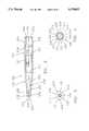
- FIG. 2is a side view in section of the tubular member of the installation tool shown in FIG. 1;
- FIG. 3is a distal end view of the tubular member shown in FIG. 2;
- FIG. 4is a proximal end view of the tubular member shown in FIG. 2;
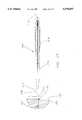
- FIG. 5is a side view of the shaft/handle of the installation tool shown in FIG. 1;
- FIG. 6is a side view, in partial section and partially cut away, showing the tubular element of FIG. 2 and the shaft of FIG. 5 in a first, retracted position relative to one another;
- FIG. 7is a side view, in partial section and partially cut away, showing the tubular element of FIG. 2 and the shaft of FIG. 5 in a second, extended position relative to one another;
- FIG. 8is a side view partially cut away of the handle shown in FIG. 5, wherein the handle has been rotated 90° about its longitudinal axis;
- FIG. 9is a sectional side view of the handle shown in FIG. 5 taken along the line A--A;
- FIG. 10is a side view of the bobbin-like element of the installation tool generally shown in FIG. 1;
- FIG. 11is an end view of the bobbin-like member shown in FIG. 10;
- FIG. 12is a sectional side view of the right hand portion of the bobbin-like member shown in FIG. 10 taken along the line B--B shown in FIG. 11;
- FIG. 13is a sectional side view of the left hand portion of the bobbin-like member shown in FIG. 10 taken along the line C--C shown in FIG. 11;
- FIG. 14is a side view in partial section showing (a) the installation tool of FIG. 1 in its first retracted configuration with the bobbin-like element in engagement with the handle, and (b) a suture anchor having its proximal portion engaging the distal end of the installation tool;
- FIG. 15is a side view in partial section showing (a) the installation tool of FIG. 1 in its first, retracted configuration, with the bobbin-like element in engagement with the handle, and (b) a suture anchor having its proximal portion engaging the distal end of the installation tool and its distal end engaging the proximal end of a hole formed in a bone;
- FIG. 16is a side view similar to FIG. 15, but showing the installation tool in its second, extended configuration, and the suture anchor disposed within the hole in the bone;
- FIG. 17is a side view similar to FIG. 16, but showing the installation tool removed from the hole and the anchor disposed at a desired position in the hole;
- FIG. 18is a side view similar to FIG. 17, but showing the suture disengaged from the continuous groove of the bobbin-like member
- FIG. 19is a side view showing the anchor disposed at a desired position in the hole, the suture disengaged from the continuous groove of the bobbin-like member, and the bobbin-like member released from the proximal portion of the handle;
- FIG. 20is a side view showing the anchor disposed at a desired position in the hole, the suture disengaged from the continuous groove of the bobbin-like member, and the bobbin-like member totally disengaged from the tool and ready for the free ends of the suture (and any needles associated therewith) to be removed therefrom;
- FIG. 21is a view similar to FIG. 1 showing an alternative installation tool and bobbin-like member formed in accordance with the invention.
- FIG. 1there are shown in exploded, illustrative relation to one another, a suture 2, a suture anchor 102, a suture anchor installation tool 202 and a target bone 302 having a hole 304 formed therein.
- Suture 2is attached to suture anchor 102.
- Installation tool 202is adapted to position anchor 102 in hole 304 formed in target bone 302.
- Installation tool 202also includes a handle 204 adapted to releasably hold a bobbin-like element 402.
- Bobbin-like element 402is adapted to releasably hold the free end(s) 4 of suture 2 and any curved surgical needles which may be attached thereto, as will hereinafter be described in detail.
- anchor 102 and anchor positioning portion 205 of installation tool 202may take any one of several forms well known in the art without departure from the present invention. Accordingly, it will be understood that the specific anchor 102 and anchor positioning portion 205 of installation tool 202 described in detail below are presented as being illustrative only, and not as limiting of the invention in its broadest aspects. These features of the preferred embodiment will be described first in order to establish a working context for the detailed description of the novel features of the invention.
- Anchor 102is representative of the preferred type of anchoring devices which are to be installed by installation tool 202.
- Such anchorstypically include (a) a body 104, (b) at least one barb 106, and (c) attachment means 108 for connecting a portion of a length of cord-like material (i.e., suture 2) to body 104.
- connection means 108is shown as a bore extending through the proximal portion of body 104 (see, for example, U.S. Pat. No. 4,898,156 and U.S. patent application Ser. No. 07/902,513).
- barbs 106are attached to body 104 in spaced, circumferential relation one to the other. Further, barbs 106 each extend rearwardly and outwardly from body 104 to respective outer ends 110. Outer ends 110 are normally located outwardly of an axial projection of the maximum, geometric, transverse cross-section of body 104. This assures that each barb 106 engages side wall 306 of target hole 304.
- Each of the barbs 106is elastically deformable. Accordingly, each barb 106 may be deflected from its normal, unstressed configuration (just described) toward a deformed, stressed configuration. In the latter configuration, each barb is located substantially within the axial projection of the maximum transverse cross-section of body 104.
- the fastening deviceis a suture anchor
- the workpieceis a piece of bone.
- the preferred embodiment of the novel installation tool 202includes a tubular element 206 (best seen in FIGS. 2-4); a shaft 208 having a handle 204 at its proximal end 210 (best seen in FIGS. 5, 8 and 9); and a bobbin-like member 402 (best seen in FIGS. 10-13).
- the tubular element 206is adapted to receive and hold a co-axially oriented portion of suture anchor 102 in its distal end 212 (see FIG. 14).
- the shaft 208is located in central lumen 214 of tubular element 206, and is movable between a first, retracted position and second, extended position (FIGS. 6 and 7).
- tubular element 206is an elongate member having a longitudinal axis 216, a distal end 212, a distal portion 218 adjacent distal end 212, a proximal end 220, a proximal portion 222 adjacent proximal end 220, a central lumen 214 extending from the distal end 212 to proximal end 220, and an outer surface 224.
- Outer surface 224defines at least one outwardly extending longitudinal rib 225.
- the distal end 212has a cross-section transverse to longitudinal axis 216 which is somewhat larger than the transverse cross-section of hole 304 in bone 302 (see FIG. 1). Further, distal portion 218 of tubular member 206 is tapered so as to form a generally distally pointed configuration.
- the side wall 230 of first counterbore 226defines a number of circumferentially spaced, longitudinal slots 232.
- the number and positioning of these slotsis selected to correspond to the number and circumferential spacing of barbs 106 of anchor 102, plus the number and circumferential spacing of the free ends of suture 2 extending from attachment means 108 of anchor 102.
- Each slot 232opens onto distal end 212 of tubular element 206.
- the slots 232 corresponding to the circumferential locations of barbs 106 of anchor 102are aligned with the ribs 225, and are sized to accommodate the barbs when anchor 102 is co-axially inserted into first counterbore 226 so that its proximal end 112 abuts shoulder 228.
- the slots 232 corresponding to the circumferential location of the free ends of suture 2 extending from attachment means 108 of anchor 102are sized to allow those free ends to extend therethrough when anchor 102 is co-axially located within first counterbore 226 (see, for example, U.S. patent application Ser. No. 07/837,061).
- third and fourth counterbores, 234, 236 and 238,extend axially into proximal end 220 of tubular element 206.
- Second counterbore 234is axially longer, and has a smaller transverse cross-section than counterbore 236.
- counterbore 236is axially longer, and has a smaller transverse cross-section than counterbore 238. Accordingly, the transverse cross-section of lumen 214 varies as it extends from proximal end 220 to distal end 212.
- the transverse cross-section of lumen 214 through tubular element 206varies from the size of counterbore 238 adjacent to proximal end 220, to the slightly smaller size of counterbore 236, to the smaller size of counterbore 234, to the still smaller size of lumen portion 221, and then to the slightly larger size of counterbore 226 adjacent distal end 212.
- a proximally facing shoulder 240is located at the junction of lumen portion 221 and second counterbore 234.
- Another proximally facing shoulder 242is located at the junction of second and third counterbores 234 and 236.
- Still another proximally facing shoulder 244is located at the junction of third and fourth counterbores 236 and 238.
- a plurality of longitudinal slots 246extend through side wall 248 of fourth counterbore 238 so as to form proximally extending, longitudinal arms, generally indicated at 250. In the particular embodiment shown, there are four slots 246 forming four arms 250 (see FIG. 4).
- Rib-like projections 252extend inwardly from side wall 248 of fourth counterbore 238 adjacent and substantially parallel to proximal end 220 of tubular element 206. Projections 252 are located respectively along side wall 248 of fourth counterbore 238 between adjacent edges of longitudinal slots 246.
- FIGS. 5-7show a solid, substantially rigid shaft 208 having a longitudinal axis 254, a proximal end 210, a distal end 258, and a handle 204 extending proximally from proximal end 210.
- the cross-section of shaft 208 perpendicular to longitudinal axis 254varies along the length of shaft 208 from a small cross-section portion 260 adjacent distal end 258, to a slightly larger cross-section portion 262, to a larger cross-section portion 264, to a still larger cross-section portion 266 adjacent proximal end 210.
- the cross-section of portion 260is selected to be smaller than the transverse cross-section of hole 304 in bone 302 (FIG. 1).
- the axial length of portion 260is selected to exceed the longitudinal distance between shoulder 240 and distal end 212 of tubular element 206.
- the amount by which the axial length of portion 260 of shaft 208 exceeds this distanceis selected to equal the depth to which proximal end 112 of body 104 is to be inserted into hole 304 in bone 302.
- a distally facing shoulder 268is located at the junction of portions 260 and 262.
- Another distally facing shoulder 270is located at the junction of portions 262 and 264.
- Still another distally facing shoulder 272is located at the junction of portions 264 and 266.
- Shoulder 268is disposed substantially perpendicularly to longitudinal axis 254. Shoulders 270 and 272, on the other hand, each taper inwardly and distally toward longitudinal axis 254.
- a rib-like projection 274extends outwardly from, and circumferentially around, portion 266.
- a groove 276extends circumferentially into and around shaft 208 substantially immediately proximally of rib-like projection 274.
- the lengths and cross-sections of the various portions of shaft 208 and the various bores and counterbores of tubular element 206are selected relative to each other so that the tubular element may be telescoped in sliding relationship onto the outer surface of the shaft. This relationship of shaft 208 and tubular element 206 is retained by a snap-fit engagement of the rib-like projections 252 carried by the proximally extending arms 250 over the outwardly extending rib-like projection 274, and into the circumferential groove 276. (See FIGS. 6 and 7).
- Shaft 208is movable longitudinally relative to tubular element 206 between a first, retracted position (FIG. 6) and a second, extended position (FIG. 7).
- first, retracted positionthe rib-like projections 252 carried by proximally extending arms 250 are snap-fit over rib-like projection 274 and into circumferential groove 276.
- distal end 258 of shaft 208resides within the smallest cross-sectional portion 221 of lumen 214. As noted above, portion 221 of lumen 214 is located immediately proximally of first counterbore 226.
- proximal end 220 of tubular element 206is located in abutting relation with a distally facing shoulder 278 formed at the junction of proximal end 210 of shaft 208 and handle 204.
- distal end 258 of shaft 208extends a preselected distance beyond distal end 212 of tubular element 206.
- an anchor 102may be co-axially located and held in the first counterbore 226 (see FIG. 14).
- the anchormay be conveniently carried to the target hole by the installation tool, as generally shown in FIG. 15.
- barbs 106 of anchor 102are held in alignment with ribs 225 on the outer surface of tubular member 206 by slots 232. This allows the surgeon to easily align the barbs in a desired relationship to the hole 304 by simply twisting tubular member 206 relative to shaft 208. Such ease of barb alignment avoids the need to twist the entire tool in order to appropriately align the barbs with the hole. Such alignment can be very important. This is because in many surgical procedures utilizing suture anchors, care must be taken to avoid barb penetration of a joint or other sensitive area either during the insertion process or upon the "setting" of the barbs.
- the anchor 102may be driven into the target hole 304 to its desired anchoring position by distal end 258 of shaft 208 (FIG. 16). This is accomplished by forcing the rib-like projections 252 carried by proximally facing arms 250 of tubular element 206 out of engagement with circumferential groove 276, and proximally along shaft portion 266 to shoulder 278.
- the handle 204(best seen in FIGS. 5, 8 and 9) comprises a distal end 280, a distal portion 282 adjacent the distal end 280, a pair of opposing substantially identical arms 284, 286 and a wall portion 288.
- Handle 204extends proximally from proximal end 210 of shaft 208.
- a distally facing shoulder 278is formed by distal end 280 adjacent the joinder of shaft 208 to handle 204.
- Distal portion 282may be a solid structure.
- distal portion 282 of handle 204comprises a pair of opposing arms 290a, 290b connected by a longitudinally extending wall 291.
- arms 290a and 290btaper outwardly from distal end 280 to outer, wide ends 292a and 292b.
- Longitudinal wall 291extends proximally from distal end 280 to end wall 293.
- End wall 293is located in a plane perpendicular to longitudinal axis 254, and connects the central portions of outer, wide ends 292a and 292b of arms 290a and 290b.
- Notches 294a and 294bare located adjacent the free side edges 295a and 295b of wall 293.
- the formation of distal portion 282 in this configurationlightens the handle, and facilitates the passage of the suture 2 from the anchor 102 through the notches 294a and/or 294b to the retention means 402.
- Arms 284 and 286extend proximally from wide ends 292a and 292b of distal portion 282 respectively.
- Each arm 284, 286defines a substantially planar, inwardly facing surface 287 and a bore 289.
- the bores 289are aligned with one another on a common axis perpendicular to the longitudinal axis 254, and are located in the proximal portion of arms 284 and 286 respectively.
- Wall portion 288connects arms 284 and 286 at a predetermined location along their longitudinal lengths approximately one-half to two-thirds of the longitudinal distance between wall 293 and the proximal end of handle 204.
- wall portion 288is oriented substantially perpendicular to both longitudinal axis 254 and planar surfaces 287.
- wall portion 288 and arms 284 and 286together define side notches 296a and 296b.
- Notches 296a and 296bare respectively longitudinally aligned with notches 294a and 294b to facilitate the passage of suture 2 along handle 204.
- the outer surfaces 297a and 297b of arms 284 and 286may be ribbed, scored or otherwise textured so as to assure that an individual using the device may firmly grasp and manipulate the same.
- flattened pressure receiving pads 299may be provided on outer surfaces 297a and 297b between connecting wall portion 288 and distal portion 282. The location of pads 299 is important because the operation of the device contemplates that inwardly directed pressure (see arrows 500, FIG. 19) will be applied to the outer surface of the portions of the arms 284 and 286 residing between distal portion 282 and connecting wall 288.
- Such inward pressurebends the portions of arms 284 and 286 located between distal portion 282 and wall portion 288 inwardly; (ii) pivots the portions of arms 284 and 286 located proximally of wall 288 about the edges thereof attached to arms 284 and 286; and (iii) moves bores 289 away from each other (see FIG. 19).
- the bobbin-like member 402(best seen in FIGS. 10-13) includes a pair of opposing, generally cylindrical, side portions 404, 406 connected in parallel, spaced relation by axle portion 408.
- the bobbin-like member 402therefore, defines a centered, continuous groove 410 between the opposing side portions 404, 406.
- Each side portion 404, 406defines a peripheral edge, 412, 414 respectively, and an outwardly facing, circular end surface 416, 418 respectively.
- An axially oriented, substantially cylindrical projection 420, 422extends outwardly from each end surface 416, 418, respectively.
- a plurality of arcuate projections, generally indicated at 424, 426extend outwardly from end surfaces 416, 418 respectively, parallel to, but a distance shorter than, the axial projections 420, 422 therefrom.
- Arcuate projections 424, 426are located adjacent to the peripheral edges 412, 414 of their associated side portions 404, 406. They are also spaced from the axial projection 420 or 422 of their associated side portion, and circumferentially spaced one from the other.
- Each of the arcuate projections 424, 426defines an outer surface, generally indicated at 428, 430 respectively, and an arc-shaped slot, generally indicated at 432, 434 respectively.
- the outer surfaces 428, 430 of arcuate projections 424, 426are located in common planes 436, 438 respectively. Planes 436 and 438 are spaced respectively outwardly from, and parallel to, an adjacent end surface of one of the side portions.
- the slots 432, 434each extend through their associated arcuate projection in concentric spaced relation to the peripheral edge of their associated side portion, and inwardly from the outer surface of the projection through the associated side portion to the continuous groove 410. Together, these arc-shaped slots define broken, circular grooves 440, 442 which are spaced radially inwardly of the peripheral edge of their respective associated side portion.
- Grooves 440, 442are adapted to releasably receive and hold a curved surgical needle 444 and/or a free end 4 of suture 2 (as shown in phantom in FIG. 11). Accordingly, grooves 440 and 442 define portions (representatively shown at 440a in FIG. 11) having a width slightly larger than the diameter of suture 2, and portions (representatively shown at 440b in FIG. 11) having widths slightly larger than the diameter of needle 444. Further, a selected one of the arcuate projections 424 and 426 (designated by the numbers 424a and 426a) extends along a greater arc than the remainder of the arcuate projections extending from its associated side portion.
- Arcuate projections 424a and 426adefine the location of the change in diameter of broken grooves 440 and 442 respectively. Accordingly, they are designed to releasably hold both a portion of the suture 2 and needle 444 attached to the free end 4 of suture 2.
- At least one of the side portions 404, 406defines a notch 446 (see FIG. 11) extending into its peripheral edge between a selected pair of the arcuate projections. Notch 446 opens into both the continuous groove 410 and the end surface of its associated side portion.
- the bobbin-like member 402is adapted to hold a portion of a length of suture 2 wrapped around the axle 408 in continuous groove 410. Another portion of that length of suture 2 extends from continuous groove 410 to attachment means 108 of anchor 102. Still another portion of that length of suture 2 extends from continuous groove 410 through notch 446 and portion 440a of groove 440 to surgical needle 444 which is releasably located in portion 440b of broken groove 440 (as shown in phantom in FIG. 11).
- the needle 444is removable from the groove 440 by inserting a needle grasping device (not shown) into one of the spaces between the arcuate projections. Such a grasping device may engage the portion of a needle extending through that space.
- a curved surgical needle and/or free end of suturemay be positioned in each of the grooves 440 and 442, or in only one of the grooves. In the preferred embodiment of the invention, surgical needles are disposed in both of the grooves 440, 442.
- piece 450includes side portion 406 having outer surface 418 and an inner surface 454.
- the cylindrical projection 422extends outwardly from outer surface 418 and defines a central bore 456 extending from its outer surface 431 to inner surface 454 of the side portion 406.
- the arcuate projections 426extend outwardly from outer surface 418 adjacent peripheral edge 414 and define the slots 434.
- arcuate projections 426aeach define a slot 434a forming the small width groove 442a
- arcuate projections 426beach define a slot 434b forming the large width groove 442b.
- small retaining lips 443a and 443bmay be provided adjacent to the openings of slots 434a and 434b into the outer surface of arcuate projections 426a and 426b.
- the extension of slots 434a and 434b through the arcuate projections parallel to the projection 422facilitates the removal of suture and/or needles disposed in the broken groove by allowing the sides thereof to spread apart to thereby permit the passage of suture or a needle inwardly past the retaining lips 443a and 443b.
- a centered, circular recessed area 458 of substantially uniform depthis formed in inner surface 454. Further, at least two, substantially equally circumferentially spaced fingers 460 extend perpendicularly inwardly from base 462 of recessed area 458. In the embodiment shown, fingers 460 extend inwardly opposite the circular space between arcuate projections 426a and 426b and cylindrical projection 422 from outer end surface 418.
- Piece 452is shown in FIG. 13.
- Piece 452includes side portion 404 having outer surface 416 and an inner surface 464.
- the cylindrical projection 420extends outwardly from outer surface 416 and defines a central bore 466 extending from its outer surface 467 perpendicularly through piece 452.
- the arcuate projections 424extend outwardly from the outer surface 416 adjacent the peripheral edge 412 and define the slots 432.
- arcuate projections 424aeach define a slot 432a forming the small width groove 442a
- arcuate projections 424beach define a slot 432b forming a large width groove 442b.
- small retaining lips 443amay be provided adjacent the opening of slots 432 into arcuate projections 424a and small retaining lips 443b may be provided adjacent the openings of slots 432 into arcuate projections 424b.
- the extension of the slots through the piecefacilitates the insertion of a suture or needle into the broken groove by allowing the outer side edges of the slots to spread apart.
- a centered, cylindrical projection 468extends perpendicularly inwardly from inner surface 464 to an inner end surface 470.
- Projection 468defines cavities 472 extending into its end surface 470 which are sized and spaced to receive the fingers 460 of piece 450.
- bore 466extends axially through projection 468.
- the bobbin-like member 402is also releasably and rotatably maintained between planar surfaces 287 of arms 284 and 286 of handle 204. This is accomplished by a snap-fit engagement of the outwardmost portions of axial projections 420, 422 with the bores 289. Bobbin-like member 402 may be disengaged from handle 204 by applying inwardly directed pressure to the portions of the arms 284 and 286 located between distal portion 282 of handle 204 and connecting wall 288.
- This pressure(i) bends the portions of the arms located between the distal portion of the handle and the connecting wall inwardly; (ii) pivots the portions of the arms located proximally of the connecting wall about the edges of the wall attached to the arms, and (iii) moves the bores away from each other.
- Bobbin-like element 402may also be rotatably mounted between the arms of the handle by reversing the procedure just described.
- the suture anchor 102is then attached to the distal end of the selected insertion tool. In the preferred embodiment, this is accomplished by co-axially inserting the proximal portion of body 104 into the first counterbore 226 in tubular member 206 while the insertion tool's shaft 208 is in its first, retracted position relative to its tubular element 206. In this configuration, barbs 106 and suture 2 both extend through slots 232. The suture extending between the continuous groove 410 and the anchor 102 may then be drawn tight against the sides of the insertion tool by rotating bobbin-like member 402 about axial projections 420, 422 located in bores 289 (see FIG. 14).
- the anchorthen is conveyed to bone hole 304 so that its distal portion resides in the hole while its proximal portion remains in counterbore 226 adjacent distal end 212 of installation tool 202 (see FIG. 15).
- the anchor 102is driven to a desired position within bone hole 304. This is accomplished by engaging distal end 212 of tubular member 206 with the bone adjacent bone hole 304. Shaft 208 then is moved relative to the tubular member 206 from its first, retracted position to its second, extended position. This ejects anchor 102 from tubular element 206 and drives anchor 102 into bone hole 304 (see FIGS. 6, 7 and 16). Distal end 258 of shaft 208 is then removed from bone hole 304, leaving anchor 102 at its desired anchoring location (see FIG. 17). Typically, the tool 202 is also removed from the immediate vicinity of the bone hole at this stage. This movement of the tool causes the bobbin-like element to rotate on its axis and the suture to be unwrapped from the axle 408 (see FIG. 18).
Landscapes
- Health & Medical Sciences (AREA)
- Surgery (AREA)
- Life Sciences & Earth Sciences (AREA)
- Biomedical Technology (AREA)
- Nuclear Medicine, Radiotherapy & Molecular Imaging (AREA)
- Engineering & Computer Science (AREA)
- Rheumatology (AREA)
- Heart & Thoracic Surgery (AREA)
- Medical Informatics (AREA)
- Molecular Biology (AREA)
- Animal Behavior & Ethology (AREA)
- General Health & Medical Sciences (AREA)
- Public Health (AREA)
- Veterinary Medicine (AREA)
- Surgical Instruments (AREA)
Abstract
Description
Claims (16)
Priority Applications (1)
| Application Number | Priority Date | Filing Date | Title |
|---|---|---|---|
| US08/098,599US5578057A (en) | 1993-07-28 | 1993-07-28 | Anchoring device installation tool assembly and method |
Applications Claiming Priority (1)
| Application Number | Priority Date | Filing Date | Title |
|---|---|---|---|
| US08/098,599US5578057A (en) | 1993-07-28 | 1993-07-28 | Anchoring device installation tool assembly and method |
Publications (1)
| Publication Number | Publication Date |
|---|---|
| US5578057Atrue US5578057A (en) | 1996-11-26 |
Family
ID=22270058
Family Applications (1)
| Application Number | Title | Priority Date | Filing Date |
|---|---|---|---|
| US08/098,599Expired - LifetimeUS5578057A (en) | 1993-07-28 | 1993-07-28 | Anchoring device installation tool assembly and method |
Country Status (1)
| Country | Link |
|---|---|
| US (1) | US5578057A (en) |
Cited By (139)
| Publication number | Priority date | Publication date | Assignee | Title |
|---|---|---|---|---|
| WO1997025928A1 (en)* | 1996-01-19 | 1997-07-24 | Mitek Surgical Products, Inc. | Bone anchor inserter, method for loading same, method for holding and delivering a bone anchor, and method for inserting a bone anchor in a bone |
| US5697950A (en)* | 1996-02-07 | 1997-12-16 | Linvatec Corporation | Pre-loaded suture anchor |
| US5707394A (en)* | 1996-02-07 | 1998-01-13 | Bristol-Myers Squibb Company | Pre-loaded suture anchor with rigid extension |
| US5814051A (en)* | 1997-06-06 | 1998-09-29 | Mitex Surgical Products, Inc. | Suture anchor insertion system |
| WO1999022648A1 (en) | 1997-10-30 | 1999-05-14 | Ethicon, Inc. | Suture anchor insertion system |
| US5944739A (en)* | 1998-03-12 | 1999-08-31 | Surgical Dynamics, Inc. | Suture anchor installation system |
| US5948000A (en) | 1996-10-03 | 1999-09-07 | United States Surgical Corporation | System for suture anchor placement |
| US5948001A (en)* | 1996-10-03 | 1999-09-07 | United States Surgical Corporation | System for suture anchor placement |
| US5980558A (en)* | 1997-09-30 | 1999-11-09 | Biomet Inc. | Suture anchor system |
| US6042583A (en)* | 1995-06-14 | 2000-03-28 | Medworks Corporation | Bone anchor-insertion tool and surgical method employing same |
| US6042601A (en)* | 1998-03-18 | 2000-03-28 | United States Surgical Corporation | Apparatus for vascular hole closure |
| US6041485A (en)* | 1997-09-22 | 2000-03-28 | Pedlick; Jack S. | System and method for anchoring a cord-like element to a workpiece |
| US6053935A (en) | 1996-11-08 | 2000-04-25 | Boston Scientific Corporation | Transvaginal anchor implantation device |
| US6077216A (en) | 1991-12-03 | 2000-06-20 | Boston Scientific Technology, Inc. | Device for transvaginally suspending the bladder neck |
| US6096041A (en) | 1998-01-27 | 2000-08-01 | Scimed Life Systems, Inc. | Bone anchors for bone anchor implantation device |
| US6146406A (en) | 1998-02-12 | 2000-11-14 | Smith & Nephew, Inc. | Bone anchor |
| US6264676B1 (en) | 1996-11-08 | 2001-07-24 | Scimed Life Systems, Inc. | Protective sheath for transvaginal anchor implantation devices |
| US20020087190A1 (en)* | 1999-02-02 | 2002-07-04 | Benavitz William C. | Insert molded push-in suture anchor |
| US20020123756A1 (en)* | 1996-10-21 | 2002-09-05 | Sauer Jude S. | Vascular hole closure |
| US20030023268A1 (en)* | 2000-10-18 | 2003-01-30 | Lizardi Jose E. | Suture anchor system and method of use |
| US6527795B1 (en) | 2000-10-18 | 2003-03-04 | Ethicon, Inc. | Knotless suture anchor system and method of use |
| US20030125750A1 (en)* | 2001-11-05 | 2003-07-03 | Zwirnmann Ralph Fritz | Spring loaded fixation element insertion device |
| US20030204195A1 (en)* | 2002-04-24 | 2003-10-30 | Michael Keane | Device for inserting surgical implants |
| US20030204193A1 (en)* | 2002-04-25 | 2003-10-30 | Stefan Gabriel | Suture anchor insertion tool |
| US6641596B1 (en) | 2000-10-18 | 2003-11-04 | Ethicon, Inc. | Knotless bioabsorbable suture anchor system and method |
| US20030216755A1 (en)* | 2001-10-22 | 2003-11-20 | Oleg Shikhman | Wound suturing device |
| US6656183B2 (en) | 2001-11-08 | 2003-12-02 | Smith & Nephew, Inc. | Tissue repair system |
| EP1234544A3 (en)* | 2001-02-27 | 2004-01-02 | Arthrex Inc | Insert molded push-in suture anchor |
| US6689153B1 (en) | 1999-04-16 | 2004-02-10 | Orthopaedic Biosystems Ltd, Inc. | Methods and apparatus for a coated anchoring device and/or suture |
| US20040097908A1 (en)* | 2001-10-22 | 2004-05-20 | Oleg Shikhman | Handle assembly for a surgical instrument |
| US6743233B1 (en) | 2000-08-02 | 2004-06-01 | Orthopaedic Biosystems, Ltd., Inc. | Medical screw and method of installation |
| US6936052B2 (en) | 2001-03-09 | 2005-08-30 | Boston Scientific Scimed, Inc. | System for implanting an implant and method thereof |
| US7025772B2 (en) | 2001-03-09 | 2006-04-11 | Scimed Life Systems, Inc. | System for implanting an implant and method thereof |
| US7131973B2 (en) | 2002-05-16 | 2006-11-07 | Boston Scientific Scimed, Inc. | Bone anchor implantation device |
| US7147641B2 (en) | 2001-05-30 | 2006-12-12 | Chen Michael C | Fixation element insertion device |
| US20070225764A1 (en)* | 1999-02-02 | 2007-09-27 | Benavitz William C | Insert molded suture anchor |
| US7361138B2 (en) | 2003-07-31 | 2008-04-22 | Scimed Life Systems, Inc. | Bioabsorbable casing for surgical sling assembly |
| US7402133B2 (en) | 2002-12-17 | 2008-07-22 | Boston Scientific Scimed, Inc. | Spacer for sling delivery system |
| US20080249545A1 (en)* | 2007-04-06 | 2008-10-09 | Interventional Therapies | Suturing, crimping and cutting device |
| EP1987779A1 (en)* | 2007-05-02 | 2008-11-05 | Arthrex, Inc. | Suture tensioning device |
| US7585311B2 (en) | 2004-06-02 | 2009-09-08 | Kfx Medical Corporation | System and method for attaching soft tissue to bone |
| US7601165B2 (en) | 2006-09-29 | 2009-10-13 | Biomet Sports Medicine, Llc | Method and apparatus for forming a self-locking adjustable suture loop |
| US7608092B1 (en) | 2004-02-20 | 2009-10-27 | Biomet Sports Medicince, LLC | Method and apparatus for performing meniscus repair |
| US7749250B2 (en) | 2006-02-03 | 2010-07-06 | Biomet Sports Medicine, Llc | Soft tissue repair assembly and associated method |
| US20100305576A1 (en)* | 2009-05-29 | 2010-12-02 | Wright Medical Technology, Inc. | Suture anchoring instrument |
| US20100324597A1 (en)* | 2009-06-19 | 2010-12-23 | Oleg Shikhman | Crimping and cutting device |
| US7857830B2 (en) | 2006-02-03 | 2010-12-28 | Biomet Sports Medicine, Llc | Soft tissue repair and conduit device |
| US7867251B2 (en) | 2001-11-08 | 2011-01-11 | Smith & Nephew, Inc. | Reattachment of tissue to base tissue |
| US7905904B2 (en) | 2006-02-03 | 2011-03-15 | Biomet Sports Medicine, Llc | Soft tissue repair device and associated methods |
| US7905903B2 (en) | 2006-02-03 | 2011-03-15 | Biomet Sports Medicine, Llc | Method for tissue fixation |
| US7909851B2 (en) | 2006-02-03 | 2011-03-22 | Biomet Sports Medicine, Llc | Soft tissue repair device and associated methods |
| US7959650B2 (en) | 2006-09-29 | 2011-06-14 | Biomet Sports Medicine, Llc | Adjustable knotless loops |
| US8033983B2 (en) | 2001-03-09 | 2011-10-11 | Boston Scientific Scimed, Inc. | Medical implant |
| US8062334B2 (en) | 2004-06-02 | 2011-11-22 | Kfx Medical Corporation | Suture anchor |
| US8088130B2 (en) | 2006-02-03 | 2012-01-03 | Biomet Sports Medicine, Llc | Method and apparatus for coupling soft tissue to a bone |
| US8118836B2 (en) | 2004-11-05 | 2012-02-21 | Biomet Sports Medicine, Llc | Method and apparatus for coupling soft tissue to a bone |
| US8128658B2 (en) | 2004-11-05 | 2012-03-06 | Biomet Sports Medicine, Llc | Method and apparatus for coupling soft tissue to bone |
| US8128698B2 (en) | 1999-10-20 | 2012-03-06 | Anulex Technologies, Inc. | Method and apparatus for the treatment of the intervertebral disc annulus |
| US8137382B2 (en) | 2004-11-05 | 2012-03-20 | Biomet Sports Medicine, Llc | Method and apparatus for coupling anatomical features |
| US8163022B2 (en) | 2008-10-14 | 2012-04-24 | Anulex Technologies, Inc. | Method and apparatus for the treatment of the intervertebral disc annulus |
| US8251998B2 (en) | 2006-08-16 | 2012-08-28 | Biomet Sports Medicine, Llc | Chondral defect repair |
| US8298262B2 (en) | 2006-02-03 | 2012-10-30 | Biomet Sports Medicine, Llc | Method for tissue fixation |
| US8303604B2 (en) | 2004-11-05 | 2012-11-06 | Biomet Sports Medicine, Llc | Soft tissue repair device and method |
| US8317825B2 (en) | 2004-11-09 | 2012-11-27 | Biomet Sports Medicine, Llc | Soft tissue conduit device and method |
| US8343227B2 (en) | 2009-05-28 | 2013-01-01 | Biomet Manufacturing Corp. | Knee prosthesis assembly with ligament link |
| US8361113B2 (en) | 2006-02-03 | 2013-01-29 | Biomet Sports Medicine, Llc | Method and apparatus for coupling soft tissue to a bone |
| US8460319B2 (en) | 2010-01-11 | 2013-06-11 | Anulex Technologies, Inc. | Intervertebral disc annulus repair system and method |
| US8500818B2 (en) | 2006-09-29 | 2013-08-06 | Biomet Manufacturing, Llc | Knee prosthesis assembly with ligament link |
| US8506597B2 (en) | 2011-10-25 | 2013-08-13 | Biomet Sports Medicine, Llc | Method and apparatus for interosseous membrane reconstruction |
| WO2013142487A1 (en)* | 2012-03-22 | 2013-09-26 | Cook Medical Technologies Llc | Suture cartridge and method of use thereof |
| US8545535B2 (en) | 2009-05-12 | 2013-10-01 | Foundry Newco Xi, Inc. | Suture anchors with one-way cinching mechanisms |
| US8556977B2 (en) | 1999-10-20 | 2013-10-15 | Anulex Technologies, Inc. | Tissue anchoring system and method |
| US8562647B2 (en) | 2006-09-29 | 2013-10-22 | Biomet Sports Medicine, Llc | Method and apparatus for securing soft tissue to bone |
| US8562645B2 (en) | 2006-09-29 | 2013-10-22 | Biomet Sports Medicine, Llc | Method and apparatus for forming a self-locking adjustable loop |
| US8574235B2 (en) | 2006-02-03 | 2013-11-05 | Biomet Sports Medicine, Llc | Method for trochanteric reattachment |
| US8597327B2 (en) | 2006-02-03 | 2013-12-03 | Biomet Manufacturing, Llc | Method and apparatus for sternal closure |
| US8652171B2 (en) | 2006-02-03 | 2014-02-18 | Biomet Sports Medicine, Llc | Method and apparatus for soft tissue fixation |
| US8652172B2 (en) | 2006-02-03 | 2014-02-18 | Biomet Sports Medicine, Llc | Flexible anchors for tissue fixation |
| US8672969B2 (en) | 2006-09-29 | 2014-03-18 | Biomet Sports Medicine, Llc | Fracture fixation device |
| US8771352B2 (en) | 2011-05-17 | 2014-07-08 | Biomet Sports Medicine, Llc | Method and apparatus for tibial fixation of an ACL graft |
| US8801755B2 (en) | 2004-04-06 | 2014-08-12 | Arthrex, Inc. | Suture anchor |
| US8801783B2 (en) | 2006-09-29 | 2014-08-12 | Biomet Sports Medicine, Llc | Prosthetic ligament system for knee joint |
| US8821541B2 (en) | 1999-02-02 | 2014-09-02 | Arthrex, Inc. | Suture anchor with insert-molded rigid member |
| CN104042263A (en)* | 2013-03-13 | 2014-09-17 | 美多斯国际有限公司 | Suture Storage Devices, Systems, And Methods |
| US8840645B2 (en) | 2004-11-05 | 2014-09-23 | Biomet Sports Medicine, Llc | Method and apparatus for coupling soft tissue to a bone |
| US8936621B2 (en) | 2006-02-03 | 2015-01-20 | Biomet Sports Medicine, Llc | Method and apparatus for forming a self-locking adjustable loop |
| US8968364B2 (en) | 2006-02-03 | 2015-03-03 | Biomet Sports Medicine, Llc | Method and apparatus for fixation of an ACL graft |
| US8998949B2 (en) | 2004-11-09 | 2015-04-07 | Biomet Sports Medicine, Llc | Soft tissue conduit device |
| US9017381B2 (en) | 2007-04-10 | 2015-04-28 | Biomet Sports Medicine, Llc | Adjustable knotless loops |
| US9078644B2 (en) | 2006-09-29 | 2015-07-14 | Biomet Sports Medicine, Llc | Fracture fixation device |
| US20150209096A1 (en)* | 2012-11-21 | 2015-07-30 | Pioneer Surgical Technology, Inc. | Tensioning instrument |
| US9095442B2 (en) | 1999-10-20 | 2015-08-04 | Krt Investors, Inc. | Method and apparatus for the treatment of the intervertebral disc annulus |
| US9114025B2 (en) | 1999-10-20 | 2015-08-25 | Krt Investors, Inc. | Methods and devices for spinal disc annulus reconstruction and repair |
| WO2015134800A1 (en)* | 2014-03-05 | 2015-09-11 | Cayenne Medical, Inc. | All-suture suture anchor systems and methods |
| US9149267B2 (en) | 2006-02-03 | 2015-10-06 | Biomet Sports Medicine, Llc | Method and apparatus for coupling soft tissue to a bone |
| US9179907B2 (en) | 2000-06-22 | 2015-11-10 | Arthrex, Inc. | Knotless graft fixation assembly |
| US9259217B2 (en) | 2012-01-03 | 2016-02-16 | Biomet Manufacturing, Llc | Suture Button |
| US9271713B2 (en) | 2006-02-03 | 2016-03-01 | Biomet Sports Medicine, Llc | Method and apparatus for tensioning a suture |
| US9314241B2 (en) | 2011-11-10 | 2016-04-19 | Biomet Sports Medicine, Llc | Apparatus for coupling soft tissue to a bone |
| US9357991B2 (en) | 2011-11-03 | 2016-06-07 | Biomet Sports Medicine, Llc | Method and apparatus for stitching tendons |
| US9370350B2 (en) | 2011-11-10 | 2016-06-21 | Biomet Sports Medicine, Llc | Apparatus for coupling soft tissue to a bone |
| US9381013B2 (en) | 2011-11-10 | 2016-07-05 | Biomet Sports Medicine, Llc | Method for coupling soft tissue to a bone |
| WO2016151334A1 (en)* | 2015-03-24 | 2016-09-29 | Summit Medical Limited | Suture anchor delivery tool |
| US9463010B2 (en) | 2009-05-12 | 2016-10-11 | The Foundry, Llc | Methods and devices to treat diseased or injured musculoskeletal tissue |
| US9521999B2 (en) | 2005-09-13 | 2016-12-20 | Arthrex, Inc. | Fully-threaded bioabsorbable suture anchor |
| US9538998B2 (en) | 2006-02-03 | 2017-01-10 | Biomet Sports Medicine, Llc | Method and apparatus for fracture fixation |
| US9615822B2 (en) | 2014-05-30 | 2017-04-11 | Biomet Sports Medicine, Llc | Insertion tools and method for soft anchor |
| US9700291B2 (en) | 2014-06-03 | 2017-07-11 | Biomet Sports Medicine, Llc | Capsule retractor |
| US9737294B2 (en) | 2013-01-28 | 2017-08-22 | Cartiva, Inc. | Method and system for orthopedic repair |
| US9757119B2 (en) | 2013-03-08 | 2017-09-12 | Biomet Sports Medicine, Llc | Visual aid for identifying suture limbs arthroscopically |
| US9801708B2 (en) | 2004-11-05 | 2017-10-31 | Biomet Sports Medicine, Llc | Method and apparatus for coupling soft tissue to a bone |
| US9901334B2 (en) | 2012-10-12 | 2018-02-27 | Cayenne Medical, Inc. | Systems and methods for repairing soft tissues using nanofiber material |
| US9918827B2 (en) | 2013-03-14 | 2018-03-20 | Biomet Sports Medicine, Llc | Scaffold for spring ligament repair |
| US9918826B2 (en) | 2006-09-29 | 2018-03-20 | Biomet Sports Medicine, Llc | Scaffold for spring ligament repair |
| US9936940B2 (en) | 2013-06-07 | 2018-04-10 | Biomet Sports Medicine, Llc | Method and apparatus for coupling soft tissue to bone |
| US9955980B2 (en) | 2015-02-24 | 2018-05-01 | Biomet Sports Medicine, Llc | Anatomic soft tissue repair |
| US10039543B2 (en) | 2014-08-22 | 2018-08-07 | Biomet Sports Medicine, Llc | Non-sliding soft anchor |
| US10136886B2 (en) | 2013-12-20 | 2018-11-27 | Biomet Sports Medicine, Llc | Knotless soft tissue devices and techniques |
| US10179012B2 (en) | 2013-01-28 | 2019-01-15 | Cartiva, Inc. | Systems and methods for orthopedic repair |
| US10314635B2 (en) | 2014-05-28 | 2019-06-11 | A&E Advanced Closure Systems, Llc | Tensioning instruments |
| US10383624B2 (en) | 2008-10-24 | 2019-08-20 | The Foundry, Llc | Methods and devices for suture anchor delivery |
| US10426459B2 (en) | 2016-07-05 | 2019-10-01 | Mortise Medical, LLC | Extra joint stabilization construct |
| WO2019191022A1 (en)* | 2018-03-27 | 2019-10-03 | Smith & Nephew, Inc. | Soft tissue anchor |
| US10463410B2 (en) | 2016-01-22 | 2019-11-05 | A&E Advanced Closure Systems, Llc | Bone plate having a connector and a connector for a surgical loop |
| US10485600B2 (en) | 2016-07-29 | 2019-11-26 | A&E Advanced Closure Systems, Llc | Surgical cable tensioner |
| US10499901B2 (en) | 2015-05-22 | 2019-12-10 | Cayenne Medical, Inc. | Systems and methods for repairing soft tissues |
| US10517587B2 (en) | 2006-02-03 | 2019-12-31 | Biomet Sports Medicine, Llc | Method and apparatus for forming a self-locking adjustable loop |
| US10765465B2 (en) | 2012-11-21 | 2020-09-08 | A&E Advanced Closure Systems, Llc | Tensioning instrument |
| US10881437B2 (en) | 2013-12-05 | 2021-01-05 | A&E Advanced Closure Systems, Llc | Bone plate system and method |
| US10912551B2 (en) | 2015-03-31 | 2021-02-09 | Biomet Sports Medicine, Llc | Suture anchor with soft anchor of electrospun fibers |
| US11259794B2 (en) | 2006-09-29 | 2022-03-01 | Biomet Sports Medicine, Llc | Method for implanting soft tissue |
| US11259792B2 (en) | 2006-02-03 | 2022-03-01 | Biomet Sports Medicine, Llc | Method and apparatus for coupling anatomical features |
| US11311287B2 (en) | 2006-02-03 | 2022-04-26 | Biomet Sports Medicine, Llc | Method for tissue fixation |
| US20220142636A1 (en)* | 2012-10-18 | 2022-05-12 | Smith & Nephew, Inc. | Flexible anchor delivery system |
| JP2022106996A (en)* | 2018-03-23 | 2022-07-20 | コンメッド コーポレーション | Suture anchor driver |
| US12096928B2 (en) | 2009-05-29 | 2024-09-24 | Biomet Sports Medicine, Llc | Method and apparatus for coupling soft tissue to a bone |
| US12245759B2 (en) | 2008-08-22 | 2025-03-11 | Biomet Sports Medicine, Llc | Method and apparatus for coupling soft tissue to bone |
| US12329373B2 (en) | 2011-05-02 | 2025-06-17 | Biomet Sports Medicine, Llc | Method and apparatus for soft tissue fixation |
| US12419632B2 (en) | 2008-08-22 | 2025-09-23 | Biomet Sports Medicine, Llc | Method and apparatus for coupling anatomical features |
Citations (8)
| Publication number | Priority date | Publication date | Assignee | Title |
|---|---|---|---|---|
| US3361382A (en)* | 1966-12-01 | 1968-01-02 | Converse Maurice | Hand-held ligature device |
| US4968315A (en)* | 1987-12-15 | 1990-11-06 | Mitek Surgical Products, Inc. | Suture anchor and suture anchor installation tool |
| US5002550A (en)* | 1989-06-06 | 1991-03-26 | Mitek Surgical Products, Inc. | Suture anchor installation tool |
| US5021059A (en)* | 1990-05-07 | 1991-06-04 | Kensey Nash Corporation | Plug device with pulley for sealing punctures in tissue and methods of use |
| US5100417A (en)* | 1990-07-13 | 1992-03-31 | American Cyanamid Company | Suture anchor and driver assembly |
| US5217486A (en)* | 1992-02-18 | 1993-06-08 | Mitek Surgical Products, Inc. | Suture anchor and installation tool |
| US5222974A (en)* | 1991-11-08 | 1993-06-29 | Kensey Nash Corporation | Hemostatic puncture closure system and method of use |
| US5224946A (en)* | 1990-07-02 | 1993-07-06 | American Cyanamid Company | Bone anchor and method of anchoring a suture to a bone |
- 1993
- 1993-07-28USUS08/098,599patent/US5578057A/ennot_activeExpired - Lifetime
Patent Citations (8)
| Publication number | Priority date | Publication date | Assignee | Title |
|---|---|---|---|---|
| US3361382A (en)* | 1966-12-01 | 1968-01-02 | Converse Maurice | Hand-held ligature device |
| US4968315A (en)* | 1987-12-15 | 1990-11-06 | Mitek Surgical Products, Inc. | Suture anchor and suture anchor installation tool |
| US5002550A (en)* | 1989-06-06 | 1991-03-26 | Mitek Surgical Products, Inc. | Suture anchor installation tool |
| US5021059A (en)* | 1990-05-07 | 1991-06-04 | Kensey Nash Corporation | Plug device with pulley for sealing punctures in tissue and methods of use |
| US5224946A (en)* | 1990-07-02 | 1993-07-06 | American Cyanamid Company | Bone anchor and method of anchoring a suture to a bone |
| US5100417A (en)* | 1990-07-13 | 1992-03-31 | American Cyanamid Company | Suture anchor and driver assembly |
| US5222974A (en)* | 1991-11-08 | 1993-06-29 | Kensey Nash Corporation | Hemostatic puncture closure system and method of use |
| US5217486A (en)* | 1992-02-18 | 1993-06-08 | Mitek Surgical Products, Inc. | Suture anchor and installation tool |
Cited By (363)
| Publication number | Priority date | Publication date | Assignee | Title |
|---|---|---|---|---|
| US6077216A (en) | 1991-12-03 | 2000-06-20 | Boston Scientific Technology, Inc. | Device for transvaginally suspending the bladder neck |
| US6042583A (en)* | 1995-06-14 | 2000-03-28 | Medworks Corporation | Bone anchor-insertion tool and surgical method employing same |
| US5662658A (en)* | 1996-01-19 | 1997-09-02 | Mitek Surgical Products, Inc. | Bone anchor inserter, method for loading same, method for holding and delivering a bone anchor, and method for inserting a bone anchor in a bone |
| WO1997025928A1 (en)* | 1996-01-19 | 1997-07-24 | Mitek Surgical Products, Inc. | Bone anchor inserter, method for loading same, method for holding and delivering a bone anchor, and method for inserting a bone anchor in a bone |
| AU708768B2 (en)* | 1996-01-19 | 1999-08-12 | Mitek Surgical Products, Inc. | Bone anchor inserter, method for loading same, method for holding and delivering a bone anchor, and method for inserting a bone anchor in a bone |
| US5697950A (en)* | 1996-02-07 | 1997-12-16 | Linvatec Corporation | Pre-loaded suture anchor |
| US5707394A (en)* | 1996-02-07 | 1998-01-13 | Bristol-Myers Squibb Company | Pre-loaded suture anchor with rigid extension |
| US5948001A (en)* | 1996-10-03 | 1999-09-07 | United States Surgical Corporation | System for suture anchor placement |
| US5948000A (en) | 1996-10-03 | 1999-09-07 | United States Surgical Corporation | System for suture anchor placement |
| US8652149B2 (en) | 1996-10-21 | 2014-02-18 | Lsi Solutions, Inc. | Vascular hole closure |
| US20020123756A1 (en)* | 1996-10-21 | 2002-09-05 | Sauer Jude S. | Vascular hole closure |
| US6053935A (en) | 1996-11-08 | 2000-04-25 | Boston Scientific Corporation | Transvaginal anchor implantation device |
| US6440154B2 (en) | 1996-11-08 | 2002-08-27 | Scimed Life Systems, Inc. | Protective sheath for transvaginal anchor implantation device |
| US6319272B1 (en) | 1996-11-08 | 2001-11-20 | Boston Scientific Corporation | Transvaginal anchor implantation device and method of use |
| US6264676B1 (en) | 1996-11-08 | 2001-07-24 | Scimed Life Systems, Inc. | Protective sheath for transvaginal anchor implantation devices |
| EP1011475A4 (en)* | 1997-06-06 | 2001-02-14 | Ethicon Inc | Suture anchor insertion system |
| US5814051A (en)* | 1997-06-06 | 1998-09-29 | Mitex Surgical Products, Inc. | Suture anchor insertion system |
| US6041485A (en)* | 1997-09-22 | 2000-03-28 | Pedlick; Jack S. | System and method for anchoring a cord-like element to a workpiece |
| US5980558A (en)* | 1997-09-30 | 1999-11-09 | Biomet Inc. | Suture anchor system |
| WO1999022648A1 (en) | 1997-10-30 | 1999-05-14 | Ethicon, Inc. | Suture anchor insertion system |
| US5944724A (en)* | 1997-10-30 | 1999-08-31 | Mitek Surgical Products, Inc. | Suture anchor insertion system |
| AU737089B2 (en)* | 1997-10-30 | 2001-08-09 | Ethicon Inc. | Suture anchor insertion system |
| US6096041A (en) | 1998-01-27 | 2000-08-01 | Scimed Life Systems, Inc. | Bone anchors for bone anchor implantation device |
| US6939355B1 (en) | 1998-01-27 | 2005-09-06 | Boston Scientific Scimed, Inc. | Bone anchors for bone anchor implantation device |
| US6146406A (en) | 1998-02-12 | 2000-11-14 | Smith & Nephew, Inc. | Bone anchor |
| US5944739A (en)* | 1998-03-12 | 1999-08-31 | Surgical Dynamics, Inc. | Suture anchor installation system |
| US6042601A (en)* | 1998-03-18 | 2000-03-28 | United States Surgical Corporation | Apparatus for vascular hole closure |
| US8821541B2 (en) | 1999-02-02 | 2014-09-02 | Arthrex, Inc. | Suture anchor with insert-molded rigid member |
| US9526493B2 (en) | 1999-02-02 | 2016-12-27 | Arthrex, Inc. | Suture anchor with insert-molded rigid member |
| US7226469B2 (en) | 1999-02-02 | 2007-06-05 | Arthrex, Inc. | Insert molded suture anchor |
| US9549726B2 (en) | 1999-02-02 | 2017-01-24 | Arthrex, Inc. | Suture anchor with insert-molded rigid member |
| US20070225764A1 (en)* | 1999-02-02 | 2007-09-27 | Benavitz William C | Insert molded suture anchor |
| US20020087190A1 (en)* | 1999-02-02 | 2002-07-04 | Benavitz William C. | Insert molded push-in suture anchor |
| US6689153B1 (en) | 1999-04-16 | 2004-02-10 | Orthopaedic Biosystems Ltd, Inc. | Methods and apparatus for a coated anchoring device and/or suture |
| US8632590B2 (en) | 1999-10-20 | 2014-01-21 | Anulex Technologies, Inc. | Apparatus and methods for the treatment of the intervertebral disc |
| US8128698B2 (en) | 1999-10-20 | 2012-03-06 | Anulex Technologies, Inc. | Method and apparatus for the treatment of the intervertebral disc annulus |
| US8556977B2 (en) | 1999-10-20 | 2013-10-15 | Anulex Technologies, Inc. | Tissue anchoring system and method |
| US9095442B2 (en) | 1999-10-20 | 2015-08-04 | Krt Investors, Inc. | Method and apparatus for the treatment of the intervertebral disc annulus |
| US9114025B2 (en) | 1999-10-20 | 2015-08-25 | Krt Investors, Inc. | Methods and devices for spinal disc annulus reconstruction and repair |
| US9675347B2 (en) | 1999-10-20 | 2017-06-13 | Krt Investors, Inc. | Apparatus for the treatment of tissue |
| US10716556B2 (en) | 2000-06-22 | 2020-07-21 | Arthtrex, Inc. | Knotless tissue fixation assembly |
| US10709436B2 (en) | 2000-06-22 | 2020-07-14 | Arthrex, Inc. | Graft fixation using a plug against suture |
| US10052091B2 (en) | 2000-06-22 | 2018-08-21 | Arthrex, Inc. | Knotless suture or tissue fixation using an implant having a pointed tip |
| US9179907B2 (en) | 2000-06-22 | 2015-11-10 | Arthrex, Inc. | Knotless graft fixation assembly |
| US9775599B2 (en) | 2000-06-22 | 2017-10-03 | Arthrex, Inc. | Knotless tissue fixation assembly |
| US9706986B2 (en) | 2000-06-22 | 2017-07-18 | Arthrex, Inc. | Knotless suture and tissue securing method |
| US6743233B1 (en) | 2000-08-02 | 2004-06-01 | Orthopaedic Biosystems, Ltd., Inc. | Medical screw and method of installation |
| US20030023268A1 (en)* | 2000-10-18 | 2003-01-30 | Lizardi Jose E. | Suture anchor system and method of use |
| US6887259B2 (en) | 2000-10-18 | 2005-05-03 | Depuy Mitek, Inc. | Suture anchor system and method of use |
| US6641596B1 (en) | 2000-10-18 | 2003-11-04 | Ethicon, Inc. | Knotless bioabsorbable suture anchor system and method |
| US7381213B2 (en) | 2000-10-18 | 2008-06-03 | Depuy Mitek, Inc. | Knotless bioabsorbable suture anchor system and method |
| US20030171778A1 (en)* | 2000-10-18 | 2003-09-11 | Lizardi Jose E. | Knotless suture anchor system and method of use |
| US6527795B1 (en) | 2000-10-18 | 2003-03-04 | Ethicon, Inc. | Knotless suture anchor system and method of use |
| US20050075668A1 (en)* | 2000-10-18 | 2005-04-07 | Lizardi Jose E. | Knotless bioabsorbable suture anchor system and method |
| EP1234544A3 (en)* | 2001-02-27 | 2004-01-02 | Arthrex Inc | Insert molded push-in suture anchor |
| US8033983B2 (en) | 2001-03-09 | 2011-10-11 | Boston Scientific Scimed, Inc. | Medical implant |
| US6936052B2 (en) | 2001-03-09 | 2005-08-30 | Boston Scientific Scimed, Inc. | System for implanting an implant and method thereof |
| US7235043B2 (en) | 2001-03-09 | 2007-06-26 | Boston Scientific Scimed Inc. | System for implanting an implant and method thereof |
| US7025772B2 (en) | 2001-03-09 | 2006-04-11 | Scimed Life Systems, Inc. | System for implanting an implant and method thereof |
| US6991597B2 (en) | 2001-03-09 | 2006-01-31 | Boston Scientific Scimed, Inc. | System for implanting an implant and method thereof |
| US8162816B2 (en) | 2001-03-09 | 2012-04-24 | Boston Scientific Scimed, Inc. | System for implanting an implant and method thereof |
| US8617048B2 (en) | 2001-03-09 | 2013-12-31 | Boston Scientific Scimed, Inc. | System for implanting an implant and method thereof |
| US7147641B2 (en) | 2001-05-30 | 2006-12-12 | Chen Michael C | Fixation element insertion device |
| US20050070918A1 (en)* | 2001-05-30 | 2005-03-31 | Zwirnmann Ralph Fritz | Spring loaded fixation element insertion device |
| US8052691B2 (en) | 2001-05-30 | 2011-11-08 | Synthes Usa, Llc | Spring loaded fixation element insertion device |
| US8758370B2 (en) | 2001-10-22 | 2014-06-24 | Interventional Therapies, Llc | Suture loading assembly |
| US20040097968A1 (en)* | 2001-10-22 | 2004-05-20 | Oleg Shikhman | Suture loading assembly |
| US20030216755A1 (en)* | 2001-10-22 | 2003-11-20 | Oleg Shikhman | Wound suturing device |
| US20040097908A1 (en)* | 2001-10-22 | 2004-05-20 | Oleg Shikhman | Handle assembly for a surgical instrument |
| US20030125750A1 (en)* | 2001-11-05 | 2003-07-03 | Zwirnmann Ralph Fritz | Spring loaded fixation element insertion device |
| US7867251B2 (en) | 2001-11-08 | 2011-01-11 | Smith & Nephew, Inc. | Reattachment of tissue to base tissue |
| US9060762B2 (en) | 2001-11-08 | 2015-06-23 | Smith & Nephew, Inc. | Reattachment of tissue to base tissue |
| US6986781B2 (en) | 2001-11-08 | 2006-01-17 | Smith & Nephew, Inc. | Tissue repair system |
| US7309337B2 (en) | 2001-11-08 | 2007-12-18 | Smith & Nephew, Inc. | Tissue repair system |
| US6656183B2 (en) | 2001-11-08 | 2003-12-02 | Smith & Nephew, Inc. | Tissue repair system |
| US20030204195A1 (en)* | 2002-04-24 | 2003-10-30 | Michael Keane | Device for inserting surgical implants |
| US6951565B2 (en) | 2002-04-24 | 2005-10-04 | Linvatec Biomaterials Ltd. | Device for inserting surgical implants |
| WO2003090627A3 (en)* | 2002-04-24 | 2004-05-13 | Linvatec Biomaterials Ltd | Device for inserting suture anchors |
| WO2003090629A3 (en)* | 2002-04-25 | 2004-04-01 | Smith & Nephew Inc | Suture anchor insertion tool |
| US20030204193A1 (en)* | 2002-04-25 | 2003-10-30 | Stefan Gabriel | Suture anchor insertion tool |
| US7674269B2 (en) | 2002-05-16 | 2010-03-09 | Boston Scientific Scimed, Inc. | Bone anchor implantation device |
| US7131973B2 (en) | 2002-05-16 | 2006-11-07 | Boston Scientific Scimed, Inc. | Bone anchor implantation device |
| US7402133B2 (en) | 2002-12-17 | 2008-07-22 | Boston Scientific Scimed, Inc. | Spacer for sling delivery system |
| US8632453B2 (en) | 2002-12-17 | 2014-01-21 | Boston Scientific Scimed, Inc. | Spacer for sling delivery system |
| US7361138B2 (en) | 2003-07-31 | 2008-04-22 | Scimed Life Systems, Inc. | Bioabsorbable casing for surgical sling assembly |
| US7824326B2 (en) | 2003-07-31 | 2010-11-02 | Boston Scientific Scimed, Inc. | Bioabsorbable casing for surgical sling assembly |
| US8221454B2 (en) | 2004-02-20 | 2012-07-17 | Biomet Sports Medicine, Llc | Apparatus for performing meniscus repair |
| US7608092B1 (en) | 2004-02-20 | 2009-10-27 | Biomet Sports Medicince, LLC | Method and apparatus for performing meniscus repair |
| US9622739B2 (en) | 2004-04-06 | 2017-04-18 | Arthrex, Inc. | Suture anchor |
| US8801755B2 (en) | 2004-04-06 | 2014-08-12 | Arthrex, Inc. | Suture anchor |
| US10537319B2 (en) | 2004-04-06 | 2020-01-21 | Arthrex, Inc. | Suture anchor |
| US8926663B2 (en) | 2004-06-02 | 2015-01-06 | Kfx Medical Corporation | System and method for attaching soft tissue to bone |
| US10561409B2 (en) | 2004-06-02 | 2020-02-18 | Kfx Medical, Llc | System and method for attaching soft tissue to bone |
| US8267964B2 (en) | 2004-06-02 | 2012-09-18 | Kfx Medical Corporation | System and method for attaching soft tissue to bone |
| US8109969B1 (en) | 2004-06-02 | 2012-02-07 | Kfx Medical Corporation | System and method for attaching soft tissue to bone |
| US8100942B1 (en) | 2004-06-02 | 2012-01-24 | Kfx Medical Corporation | System and method for attaching soft tissue to bone |
| US9655611B2 (en) | 2004-06-02 | 2017-05-23 | Kfx Medical, Llc | System and method for attaching soft tissue to bone |
| US8951287B1 (en) | 2004-06-02 | 2015-02-10 | Kfx Medical Corporation | System and method for attaching soft tissue to bone |
| US8529601B2 (en) | 2004-06-02 | 2013-09-10 | Kfx Medical Corporation | System and method for attaching soft tissue to bone |
| US8512378B2 (en) | 2004-06-02 | 2013-08-20 | Kfx Medical Corporation | Suture anchor |
| US8062334B2 (en) | 2004-06-02 | 2011-11-22 | Kfx Medical Corporation | Suture anchor |
| US9414835B1 (en) | 2004-06-02 | 2016-08-16 | Kfx Medical, Llc | System and method for attaching soft tissue to bone |
| US7585311B2 (en) | 2004-06-02 | 2009-09-08 | Kfx Medical Corporation | System and method for attaching soft tissue to bone |
| US9044226B2 (en) | 2004-06-02 | 2015-06-02 | Kfx Medical Corporation | System and method for attaching soft tissue to bone |
| US9504460B2 (en) | 2004-11-05 | 2016-11-29 | Biomet Sports Medicine, LLC. | Soft tissue repair device and method |
| US8118836B2 (en) | 2004-11-05 | 2012-02-21 | Biomet Sports Medicine, Llc | Method and apparatus for coupling soft tissue to a bone |
| US10265064B2 (en) | 2004-11-05 | 2019-04-23 | Biomet Sports Medicine, Llc | Soft tissue repair device and method |
| US9801708B2 (en) | 2004-11-05 | 2017-10-31 | Biomet Sports Medicine, Llc | Method and apparatus for coupling soft tissue to a bone |
| US9572655B2 (en) | 2004-11-05 | 2017-02-21 | Biomet Sports Medicine, Llc | Method and apparatus for coupling soft tissue to a bone |
| US8303604B2 (en) | 2004-11-05 | 2012-11-06 | Biomet Sports Medicine, Llc | Soft tissue repair device and method |
| US8128658B2 (en) | 2004-11-05 | 2012-03-06 | Biomet Sports Medicine, Llc | Method and apparatus for coupling soft tissue to bone |
| US8137382B2 (en) | 2004-11-05 | 2012-03-20 | Biomet Sports Medicine, Llc | Method and apparatus for coupling anatomical features |
| US8551140B2 (en) | 2004-11-05 | 2013-10-08 | Biomet Sports Medicine, Llc | Method and apparatus for coupling soft tissue to bone |
| US11109857B2 (en) | 2004-11-05 | 2021-09-07 | Biomet Sports Medicine, Llc | Soft tissue repair device and method |
| US8840645B2 (en) | 2004-11-05 | 2014-09-23 | Biomet Sports Medicine, Llc | Method and apparatus for coupling soft tissue to a bone |
| US8317825B2 (en) | 2004-11-09 | 2012-11-27 | Biomet Sports Medicine, Llc | Soft tissue conduit device and method |
| US8998949B2 (en) | 2004-11-09 | 2015-04-07 | Biomet Sports Medicine, Llc | Soft tissue conduit device |
| US10595847B2 (en) | 2005-09-13 | 2020-03-24 | Arthrex, Inc. | Fully-threaded bioabsorbable suture anchor |
| US9521999B2 (en) | 2005-09-13 | 2016-12-20 | Arthrex, Inc. | Fully-threaded bioabsorbable suture anchor |
| US11324493B2 (en) | 2005-09-13 | 2022-05-10 | Arthrex, Inc. | Fully-threaded bioabsorbable suture anchor |
| US12064104B2 (en) | 2005-09-13 | 2024-08-20 | Arthrex, Inc. | Fully-threaded bioabsorbable suture anchor |
| US9498204B2 (en) | 2006-02-03 | 2016-11-22 | Biomet Sports Medicine, Llc | Method and apparatus for coupling anatomical features |
| US10695052B2 (en) | 2006-02-03 | 2020-06-30 | Biomet Sports Medicine, Llc | Method and apparatus for coupling soft tissue to a bone |
| US8608777B2 (en) | 2006-02-03 | 2013-12-17 | Biomet Sports Medicine | Method and apparatus for coupling soft tissue to a bone |
| US12096931B2 (en) | 2006-02-03 | 2024-09-24 | Biomet Sports Medicine, Llc | Method and apparatus for coupling soft tissue to a bone |
| US8652171B2 (en) | 2006-02-03 | 2014-02-18 | Biomet Sports Medicine, Llc | Method and apparatus for soft tissue fixation |
| US8652172B2 (en) | 2006-02-03 | 2014-02-18 | Biomet Sports Medicine, Llc | Flexible anchors for tissue fixation |
| US7857830B2 (en) | 2006-02-03 | 2010-12-28 | Biomet Sports Medicine, Llc | Soft tissue repair and conduit device |
| US10251637B2 (en) | 2006-02-03 | 2019-04-09 | Biomet Sports Medicine, Llc | Soft tissue repair device and associated methods |
| US8721684B2 (en) | 2006-02-03 | 2014-05-13 | Biomet Sports Medicine, Llc | Method and apparatus for coupling anatomical features |
| US8597327B2 (en) | 2006-02-03 | 2013-12-03 | Biomet Manufacturing, Llc | Method and apparatus for sternal closure |
| US12064101B2 (en) | 2006-02-03 | 2024-08-20 | Biomet Sports Medicine, Llc | Method and apparatus for forming a self-locking adjustable loop |
| US8771316B2 (en) | 2006-02-03 | 2014-07-08 | Biomet Sports Medicine, Llc | Method and apparatus for coupling anatomical features |
| US10398428B2 (en) | 2006-02-03 | 2019-09-03 | Biomet Sports Medicine, Llc | Method and apparatus for coupling anatomical features |
| US8574235B2 (en) | 2006-02-03 | 2013-11-05 | Biomet Sports Medicine, Llc | Method for trochanteric reattachment |
| US10154837B2 (en) | 2006-02-03 | 2018-12-18 | Biomet Sports Medicine, Llc | Method and apparatus for coupling soft tissue to a bone |
| US10441264B2 (en) | 2006-02-03 | 2019-10-15 | Biomet Sports Medicine, Llc | Soft tissue repair assembly and associated method |
| US10098629B2 (en) | 2006-02-03 | 2018-10-16 | Biomet Sports Medicine, Llc | Method and apparatus for coupling soft tissue to a bone |
| US10092288B2 (en) | 2006-02-03 | 2018-10-09 | Biomet Sports Medicine, Llc | Method and apparatus for coupling soft tissue to a bone |
| US11998185B2 (en) | 2006-02-03 | 2024-06-04 | Biomet Sports Medicine, Llc | Method and apparatus for coupling soft tissue to a bone |
| US11896210B2 (en) | 2006-02-03 | 2024-02-13 | Biomet Sports Medicine, Llc | Method and apparatus for coupling soft tissue to a bone |
| US11819205B2 (en) | 2006-02-03 | 2023-11-21 | Biomet Sports Medicine, Llc | Soft tissue repair device and associated methods |
| US8932331B2 (en) | 2006-02-03 | 2015-01-13 | Biomet Sports Medicine, Llc | Method and apparatus for coupling soft tissue to bone |
| US8936621B2 (en) | 2006-02-03 | 2015-01-20 | Biomet Sports Medicine, Llc | Method and apparatus for forming a self-locking adjustable loop |
| US11786236B2 (en) | 2006-02-03 | 2023-10-17 | Biomet Sports Medicine, Llc | Method and apparatus for coupling anatomical features |
| US11730464B2 (en) | 2006-02-03 | 2023-08-22 | Biomet Sports Medicine, Llc | Soft tissue repair assembly and associated method |
| US8968364B2 (en) | 2006-02-03 | 2015-03-03 | Biomet Sports Medicine, Llc | Method and apparatus for fixation of an ACL graft |
| US11723648B2 (en) | 2006-02-03 | 2023-08-15 | Biomet Sports Medicine, Llc | Method and apparatus for soft tissue fixation |
| US9005287B2 (en) | 2006-02-03 | 2015-04-14 | Biomet Sports Medicine, Llc | Method for bone reattachment |
| US10517587B2 (en) | 2006-02-03 | 2019-12-31 | Biomet Sports Medicine, Llc | Method and apparatus for forming a self-locking adjustable loop |
| US10542967B2 (en) | 2006-02-03 | 2020-01-28 | Biomet Sports Medicine, Llc | Method and apparatus for coupling soft tissue to a bone |
| US11617572B2 (en) | 2006-02-03 | 2023-04-04 | Biomet Sports Medicine, Llc | Soft tissue repair device and associated methods |
| US7905904B2 (en) | 2006-02-03 | 2011-03-15 | Biomet Sports Medicine, Llc | Soft tissue repair device and associated methods |
| US7749250B2 (en) | 2006-02-03 | 2010-07-06 | Biomet Sports Medicine, Llc | Soft tissue repair assembly and associated method |
| US11589859B2 (en) | 2006-02-03 | 2023-02-28 | Biomet Sports Medicine, Llc | Method and apparatus for coupling soft tissue to bone |
| US8409253B2 (en) | 2006-02-03 | 2013-04-02 | Biomet Sports Medicine, Llc | Soft tissue repair assembly and associated method |
| US11471147B2 (en) | 2006-02-03 | 2022-10-18 | Biomet Sports Medicine, Llc | Method and apparatus for coupling soft tissue to a bone |
| US9149267B2 (en) | 2006-02-03 | 2015-10-06 | Biomet Sports Medicine, Llc | Method and apparatus for coupling soft tissue to a bone |
| US9173651B2 (en) | 2006-02-03 | 2015-11-03 | Biomet Sports Medicine, Llc | Soft tissue repair device and associated methods |
| US8361113B2 (en) | 2006-02-03 | 2013-01-29 | Biomet Sports Medicine, Llc | Method and apparatus for coupling soft tissue to a bone |
| US11446019B2 (en) | 2006-02-03 | 2022-09-20 | Biomet Sports Medicine, Llc | Method and apparatus for coupling soft tissue to a bone |
| US10022118B2 (en) | 2006-02-03 | 2018-07-17 | Biomet Sports Medicine, Llc | Method and apparatus for coupling soft tissue to a bone |
| US11317907B2 (en) | 2006-02-03 | 2022-05-03 | Biomet Sports Medicine, Llc | Method and apparatus for forming a self-locking adjustable loop |
| US9271713B2 (en) | 2006-02-03 | 2016-03-01 | Biomet Sports Medicine, Llc | Method and apparatus for tensioning a suture |
| US11311287B2 (en) | 2006-02-03 | 2022-04-26 | Biomet Sports Medicine, Llc | Method for tissue fixation |
| US11284884B2 (en) | 2006-02-03 | 2022-03-29 | Biomet Sports Medicine, Llc | Method and apparatus for coupling soft tissue to a bone |
| US11259792B2 (en) | 2006-02-03 | 2022-03-01 | Biomet Sports Medicine, Llc | Method and apparatus for coupling anatomical features |
| US10004588B2 (en) | 2006-02-03 | 2018-06-26 | Biomet Sports Medicine, Llc | Method and apparatus for fixation of an ACL graft |
| US8632569B2 (en) | 2006-02-03 | 2014-01-21 | Biomet Sports Medicine, Llc | Soft tissue repair device and associated methods |
| US11116495B2 (en) | 2006-02-03 | 2021-09-14 | Biomet Sports Medicine, Llc | Soft tissue repair assembly and associated method |
| US9402621B2 (en) | 2006-02-03 | 2016-08-02 | Biomet Sports Medicine, LLC. | Method for tissue fixation |
| US10004489B2 (en) | 2006-02-03 | 2018-06-26 | Biomet Sports Medicine, Llc | Method and apparatus for coupling soft tissue to a bone |
| US9414833B2 (en) | 2006-02-03 | 2016-08-16 | Biomet Sports Medicine, Llc | Soft tissue repair assembly and associated method |
| US9993241B2 (en) | 2006-02-03 | 2018-06-12 | Biomet Sports Medicine, Llc | Method and apparatus for forming a self-locking adjustable loop |
| US11065103B2 (en) | 2006-02-03 | 2021-07-20 | Biomet Sports Medicine, Llc | Method and apparatus for fixation of an ACL graft |
| US11039826B2 (en) | 2006-02-03 | 2021-06-22 | Biomet Sports Medicine, Llc | Method and apparatus for forming a self-locking adjustable loop |
| US10987099B2 (en) | 2006-02-03 | 2021-04-27 | Biomet Sports Medicine, Llc | Method for tissue fixation |
| US10973507B2 (en) | 2006-02-03 | 2021-04-13 | Biomet Sports Medicine, Llc | Method and apparatus for coupling soft tissue to a bone |
| US9468433B2 (en) | 2006-02-03 | 2016-10-18 | Biomet Sports Medicine, Llc | Method and apparatus for forming a self-locking adjustable loop |
| US10595851B2 (en) | 2006-02-03 | 2020-03-24 | Biomet Sports Medicine, Llc | Method and apparatus for coupling soft tissue to a bone |
| US9492158B2 (en) | 2006-02-03 | 2016-11-15 | Biomet Sports Medicine, Llc | Method and apparatus for coupling soft tissue to a bone |
| US8337525B2 (en) | 2006-02-03 | 2012-12-25 | Biomet Sports Medicine, Llc | Soft tissue repair device and associated methods |
| US10932770B2 (en) | 2006-02-03 | 2021-03-02 | Biomet Sports Medicine, Llc | Soft tissue repair device and associated methods |
| US9510819B2 (en) | 2006-02-03 | 2016-12-06 | Biomet Sports Medicine, Llc | Soft tissue repair device and associated methods |
| US9510821B2 (en) | 2006-02-03 | 2016-12-06 | Biomet Sports Medicine, Llc | Method and apparatus for coupling anatomical features |
| US8298262B2 (en) | 2006-02-03 | 2012-10-30 | Biomet Sports Medicine, Llc | Method for tissue fixation |
| US8292921B2 (en) | 2006-02-03 | 2012-10-23 | Biomet Sports Medicine, Llc | Soft tissue repair device and associated methods |
| US9532777B2 (en) | 2006-02-03 | 2017-01-03 | Biomet Sports Medicine, Llc | Method and apparatus for coupling soft tissue to a bone |
| US10603029B2 (en) | 2006-02-03 | 2020-03-31 | Biomet Sports Medicine, Llc | Method and apparatus for coupling soft tissue to bone |
| US10675073B2 (en) | 2006-02-03 | 2020-06-09 | Biomet Sports Medicine, Llc | Method and apparatus for sternal closure |
| US9538998B2 (en) | 2006-02-03 | 2017-01-10 | Biomet Sports Medicine, Llc | Method and apparatus for fracture fixation |
| US10687803B2 (en) | 2006-02-03 | 2020-06-23 | Biomet Sports Medicine, Llc | Method and apparatus for coupling soft tissue to a bone |
| US8273106B2 (en) | 2006-02-03 | 2012-09-25 | Biomet Sports Medicine, Llc | Soft tissue repair and conduit device |
| US9561025B2 (en) | 2006-02-03 | 2017-02-07 | Biomet Sports Medicine, Llc | Soft tissue repair device and associated methods |
| US10729421B2 (en) | 2006-02-03 | 2020-08-04 | Biomet Sports Medicine, Llc | Method and apparatus for soft tissue fixation |
| US7905903B2 (en) | 2006-02-03 | 2011-03-15 | Biomet Sports Medicine, Llc | Method for tissue fixation |
| US9603591B2 (en) | 2006-02-03 | 2017-03-28 | Biomet Sports Medicine, Llc | Flexible anchors for tissue fixation |
| US10729430B2 (en) | 2006-02-03 | 2020-08-04 | Biomet Sports Medicine, Llc | Method and apparatus for coupling soft tissue to a bone |
| US9622736B2 (en) | 2006-02-03 | 2017-04-18 | Biomet Sports Medicine, Llc | Soft tissue repair device and associated methods |
| US9801620B2 (en) | 2006-02-03 | 2017-10-31 | Biomet Sports Medicine, Llc | Method and apparatus for coupling soft tissue to bone |
| US10716557B2 (en) | 2006-02-03 | 2020-07-21 | Biomet Sports Medicine, Llc | Method and apparatus for coupling anatomical features |
| US9642661B2 (en) | 2006-02-03 | 2017-05-09 | Biomet Sports Medicine, Llc | Method and Apparatus for Sternal Closure |
| US10321906B2 (en) | 2006-02-03 | 2019-06-18 | Biomet Sports Medicine, Llc | Method for tissue fixation |
| US8088130B2 (en) | 2006-02-03 | 2012-01-03 | Biomet Sports Medicine, Llc | Method and apparatus for coupling soft tissue to a bone |
| US7909851B2 (en) | 2006-02-03 | 2011-03-22 | Biomet Sports Medicine, Llc | Soft tissue repair device and associated methods |
| US9763656B2 (en) | 2006-02-03 | 2017-09-19 | Biomet Sports Medicine, Llc | Method and apparatus for soft tissue fixation |
| US10702259B2 (en) | 2006-02-03 | 2020-07-07 | Biomet Sports Medicine, Llc | Soft tissue repair assembly and associated method |
| US8251998B2 (en) | 2006-08-16 | 2012-08-28 | Biomet Sports Medicine, Llc | Chondral defect repair |
| US8777956B2 (en) | 2006-08-16 | 2014-07-15 | Biomet Sports Medicine, Llc | Chondral defect repair |
| US11096684B2 (en) | 2006-09-29 | 2021-08-24 | Biomet Sports Medicine, Llc | Method and apparatus for forming a self-locking adjustable loop |
| US10004493B2 (en) | 2006-09-29 | 2018-06-26 | Biomet Sports Medicine, Llc | Method for implanting soft tissue |
| US9681940B2 (en) | 2006-09-29 | 2017-06-20 | Biomet Sports Medicine, Llc | Ligament system for knee joint |
| US9788876B2 (en) | 2006-09-29 | 2017-10-17 | Biomet Sports Medicine, Llc | Fracture fixation device |
| US7601165B2 (en) | 2006-09-29 | 2009-10-13 | Biomet Sports Medicine, Llc | Method and apparatus for forming a self-locking adjustable suture loop |
| US8231654B2 (en) | 2006-09-29 | 2012-07-31 | Biomet Sports Medicine, Llc | Adjustable knotless loops |
| US10695045B2 (en) | 2006-09-29 | 2020-06-30 | Biomet Sports Medicine, Llc | Method and apparatus for attaching soft tissue to bone |
| US9833230B2 (en) | 2006-09-29 | 2017-12-05 | Biomet Sports Medicine, Llc | Fracture fixation device |
| US10743925B2 (en) | 2006-09-29 | 2020-08-18 | Biomet Sports Medicine, Llc | Fracture fixation device |
| US9539003B2 (en) | 2006-09-29 | 2017-01-10 | Biomet Sports Medicine, LLC. | Method and apparatus for forming a self-locking adjustable loop |
| US10610217B2 (en) | 2006-09-29 | 2020-04-07 | Biomet Sports Medicine, Llc | Method and apparatus for forming a self-locking adjustable loop |
| US9918826B2 (en) | 2006-09-29 | 2018-03-20 | Biomet Sports Medicine, Llc | Scaffold for spring ligament repair |
| US10835232B2 (en) | 2006-09-29 | 2020-11-17 | Biomet Sports Medicine, Llc | Fracture fixation device |
| US9486211B2 (en) | 2006-09-29 | 2016-11-08 | Biomet Sports Medicine, Llc | Method for implanting soft tissue |
| US9724090B2 (en) | 2006-09-29 | 2017-08-08 | Biomet Manufacturing, Llc | Method and apparatus for attaching soft tissue to bone |
| US9414925B2 (en) | 2006-09-29 | 2016-08-16 | Biomet Manufacturing, Llc | Method of implanting a knee prosthesis assembly with a ligament link |
| US7658751B2 (en) | 2006-09-29 | 2010-02-09 | Biomet Sports Medicine, Llc | Method for implanting soft tissue |
| US11376115B2 (en) | 2006-09-29 | 2022-07-05 | Biomet Sports Medicine, Llc | Prosthetic ligament system for knee joint |
| US11259794B2 (en) | 2006-09-29 | 2022-03-01 | Biomet Sports Medicine, Llc | Method for implanting soft tissue |
| US10349931B2 (en) | 2006-09-29 | 2019-07-16 | Biomet Sports Medicine, Llc | Fracture fixation device |
| US9078644B2 (en) | 2006-09-29 | 2015-07-14 | Biomet Sports Medicine, Llc | Fracture fixation device |
| US8500818B2 (en) | 2006-09-29 | 2013-08-06 | Biomet Manufacturing, Llc | Knee prosthesis assembly with ligament link |
| US10517714B2 (en) | 2006-09-29 | 2019-12-31 | Biomet Sports Medicine, Llc | Ligament system for knee joint |
| US11672527B2 (en) | 2006-09-29 | 2023-06-13 | Biomet Sports Medicine, Llc | Method for implanting soft tissue |
| US8562647B2 (en) | 2006-09-29 | 2013-10-22 | Biomet Sports Medicine, Llc | Method and apparatus for securing soft tissue to bone |
| US8672968B2 (en) | 2006-09-29 | 2014-03-18 | Biomet Sports Medicine, Llc | Method for implanting soft tissue |
| US8562645B2 (en) | 2006-09-29 | 2013-10-22 | Biomet Sports Medicine, Llc | Method and apparatus for forming a self-locking adjustable loop |
| US10398430B2 (en) | 2006-09-29 | 2019-09-03 | Biomet Sports Medicine, Llc | Method for implanting soft tissue |
| US8801783B2 (en) | 2006-09-29 | 2014-08-12 | Biomet Sports Medicine, Llc | Prosthetic ligament system for knee joint |
| US7959650B2 (en) | 2006-09-29 | 2011-06-14 | Biomet Sports Medicine, Llc | Adjustable knotless loops |
| US8672969B2 (en) | 2006-09-29 | 2014-03-18 | Biomet Sports Medicine, Llc | Fracture fixation device |
| US11612391B2 (en) | 2007-01-16 | 2023-03-28 | Biomet Sports Medicine, Llc | Soft tissue repair device and associated methods |
| US20080249545A1 (en)* | 2007-04-06 | 2008-10-09 | Interventional Therapies | Suturing, crimping and cutting device |
| US11185320B2 (en) | 2007-04-10 | 2021-11-30 | Biomet Sports Medicine, Llc | Adjustable knotless loops |
| US10729423B2 (en) | 2007-04-10 | 2020-08-04 | Biomet Sports Medicine, Llc | Adjustable knotless loops |
| US9017381B2 (en) | 2007-04-10 | 2015-04-28 | Biomet Sports Medicine, Llc | Adjustable knotless loops |
| US9861351B2 (en) | 2007-04-10 | 2018-01-09 | Biomet Sports Medicine, Llc | Adjustable knotless loops |
| US12303122B2 (en) | 2007-04-10 | 2025-05-20 | Biomet Sports Medicine, Llc | Adjustable knotless loops |
| US20080275477A1 (en)* | 2007-05-02 | 2008-11-06 | Arthrex, Inc. | Suture tensioning device |
| EP1987779A1 (en)* | 2007-05-02 | 2008-11-05 | Arthrex, Inc. | Suture tensioning device |
| US8298247B2 (en) | 2007-05-02 | 2012-10-30 | Arthrex, Inc. | Suture tensioning device |
| US8939999B2 (en) | 2007-05-02 | 2015-01-27 | Arthrex, Inc. | Suture tensioning device |
| US12245759B2 (en) | 2008-08-22 | 2025-03-11 | Biomet Sports Medicine, Llc | Method and apparatus for coupling soft tissue to bone |
| US11534159B2 (en) | 2008-08-22 | 2022-12-27 | Biomet Sports Medicine, Llc | Method and apparatus for coupling soft tissue to a bone |
| US12419632B2 (en) | 2008-08-22 | 2025-09-23 | Biomet Sports Medicine, Llc | Method and apparatus for coupling anatomical features |
| US9192372B2 (en) | 2008-10-14 | 2015-11-24 | Krt Investors, Inc. | Method for the treatment of tissue |
| US8163022B2 (en) | 2008-10-14 | 2012-04-24 | Anulex Technologies, Inc. | Method and apparatus for the treatment of the intervertebral disc annulus |
| US8454697B2 (en) | 2008-10-14 | 2013-06-04 | Anulex Technologies, Inc. | Method and apparatus for the treatment of tissue |
| US10383624B2 (en) | 2008-10-24 | 2019-08-20 | The Foundry, Llc | Methods and devices for suture anchor delivery |
| US11272925B2 (en) | 2008-10-24 | 2022-03-15 | The Foundry, Llc | Methods and devices for suture anchor delivery |
| US10582919B2 (en) | 2009-05-12 | 2020-03-10 | The Foundry, Llc | Suture anchors with one-way cinching mechanisms |
| US8545535B2 (en) | 2009-05-12 | 2013-10-01 | Foundry Newco Xi, Inc. | Suture anchors with one-way cinching mechanisms |
| US9463010B2 (en) | 2009-05-12 | 2016-10-11 | The Foundry, Llc | Methods and devices to treat diseased or injured musculoskeletal tissue |
| US10588614B2 (en) | 2009-05-12 | 2020-03-17 | The Foundry, Llc | Methods and devices to treat diseased or injured musculoskeletal tissue |
| US11000267B2 (en) | 2009-05-12 | 2021-05-11 | The Foundry, Llc | Knotless suture anchor and methods of use |
| US9539000B2 (en) | 2009-05-12 | 2017-01-10 | The Foundry, Llc | Knotless suture anchor and methods of use |
| US8900314B2 (en) | 2009-05-28 | 2014-12-02 | Biomet Manufacturing, Llc | Method of implanting a prosthetic knee joint assembly |
| US8343227B2 (en) | 2009-05-28 | 2013-01-01 | Biomet Manufacturing Corp. | Knee prosthesis assembly with ligament link |
| US10149767B2 (en) | 2009-05-28 | 2018-12-11 | Biomet Manufacturing, Llc | Method of implanting knee prosthesis assembly with ligament link |
| US20100305576A1 (en)* | 2009-05-29 | 2010-12-02 | Wright Medical Technology, Inc. | Suture anchoring instrument |
| US12096928B2 (en) | 2009-05-29 | 2024-09-24 | Biomet Sports Medicine, Llc | Method and apparatus for coupling soft tissue to a bone |
| US12251093B2 (en) | 2009-05-29 | 2025-03-18 | Biomet Sports Medicine, Llc | Method and apparatus for coupling soft tissue to a bone |
| US20100324597A1 (en)* | 2009-06-19 | 2010-12-23 | Oleg Shikhman | Crimping and cutting device |
| US8460319B2 (en) | 2010-01-11 | 2013-06-11 | Anulex Technologies, Inc. | Intervertebral disc annulus repair system and method |
| US9795372B2 (en) | 2010-01-11 | 2017-10-24 | Krt Investors, Inc. | Intervertebral disc annulus repair system and bone anchor delivery tool |
| US8652153B2 (en) | 2010-01-11 | 2014-02-18 | Anulex Technologies, Inc. | Intervertebral disc annulus repair system and bone anchor delivery tool |
| US12329373B2 (en) | 2011-05-02 | 2025-06-17 | Biomet Sports Medicine, Llc | Method and apparatus for soft tissue fixation |
| US12336701B2 (en) | 2011-05-02 | 2025-06-24 | Biomet Sports Medicine, Llc | Method and apparatus for soft tissue fixation |
| US9216078B2 (en) | 2011-05-17 | 2015-12-22 | Biomet Sports Medicine, Llc | Method and apparatus for tibial fixation of an ACL graft |
| US8771352B2 (en) | 2011-05-17 | 2014-07-08 | Biomet Sports Medicine, Llc | Method and apparatus for tibial fixation of an ACL graft |
| US8506597B2 (en) | 2011-10-25 | 2013-08-13 | Biomet Sports Medicine, Llc | Method and apparatus for interosseous membrane reconstruction |
| US9445827B2 (en) | 2011-10-25 | 2016-09-20 | Biomet Sports Medicine, Llc | Method and apparatus for intraosseous membrane reconstruction |
| US10265159B2 (en) | 2011-11-03 | 2019-04-23 | Biomet Sports Medicine, Llc | Method and apparatus for stitching tendons |
| US11241305B2 (en) | 2011-11-03 | 2022-02-08 | Biomet Sports Medicine, Llc | Method and apparatus for stitching tendons |
| US9357991B2 (en) | 2011-11-03 | 2016-06-07 | Biomet Sports Medicine, Llc | Method and apparatus for stitching tendons |
| US9381013B2 (en) | 2011-11-10 | 2016-07-05 | Biomet Sports Medicine, Llc | Method for coupling soft tissue to a bone |
| US11534157B2 (en) | 2011-11-10 | 2022-12-27 | Biomet Sports Medicine, Llc | Method for coupling soft tissue to a bone |
| US9314241B2 (en) | 2011-11-10 | 2016-04-19 | Biomet Sports Medicine, Llc | Apparatus for coupling soft tissue to a bone |
| US10363028B2 (en) | 2011-11-10 | 2019-07-30 | Biomet Sports Medicine, Llc | Method for coupling soft tissue to a bone |
| US9357992B2 (en) | 2011-11-10 | 2016-06-07 | Biomet Sports Medicine, Llc | Method for coupling soft tissue to a bone |
| US9370350B2 (en) | 2011-11-10 | 2016-06-21 | Biomet Sports Medicine, Llc | Apparatus for coupling soft tissue to a bone |
| US10368856B2 (en) | 2011-11-10 | 2019-08-06 | Biomet Sports Medicine, Llc | Apparatus for coupling soft tissue to a bone |
| US9259217B2 (en) | 2012-01-03 | 2016-02-16 | Biomet Manufacturing, Llc | Suture Button |
| US9433407B2 (en) | 2012-01-03 | 2016-09-06 | Biomet Manufacturing, Llc | Method of implanting a bone fixation assembly |
| WO2013142487A1 (en)* | 2012-03-22 | 2013-09-26 | Cook Medical Technologies Llc | Suture cartridge and method of use thereof |
| US11759198B2 (en) | 2012-10-12 | 2023-09-19 | Cayenne Medical, Inc. | Systems and methods for repairing soft tissues using nanofiber material |
| US9901334B2 (en) | 2012-10-12 | 2018-02-27 | Cayenne Medical, Inc. | Systems and methods for repairing soft tissues using nanofiber material |
| US10631849B2 (en) | 2012-10-12 | 2020-04-28 | Cayenne Medical, Inc. | Systems and methods for repairing soft tissues using nanofiber material |
| US12185937B2 (en) | 2012-10-12 | 2025-01-07 | Cayenne Medical, Inc. | Systems and methods for repairing soft tissues using nanofiber material |
| US11534155B2 (en) | 2012-10-12 | 2022-12-27 | Cayenne Medical, Inc. | Systems and methods for repairing soft tissues using nanofiber material |
| US12357296B2 (en) | 2012-10-12 | 2025-07-15 | Cayenne Medical, Inc. | Systems and methods for repairing soft tissues using nanofiber material |
| US12096929B2 (en)* | 2012-10-18 | 2024-09-24 | Smith & Nephew, Inc. | Flexible anchor delivery system |
| US20230329696A1 (en)* | 2012-10-18 | 2023-10-19 | Smith & Nephew, Inc. | Flexible anchor delivery system |
| US20220142636A1 (en)* | 2012-10-18 | 2022-05-12 | Smith & Nephew, Inc. | Flexible anchor delivery system |
| US9333021B2 (en)* | 2012-11-21 | 2016-05-10 | Pioneer Surgical Technology, Inc. | Tensioning instrument |
| US20150209096A1 (en)* | 2012-11-21 | 2015-07-30 | Pioneer Surgical Technology, Inc. | Tensioning instrument |
| US10426532B2 (en) | 2012-11-21 | 2019-10-01 | A&E Advanced Closure Systems, Llc | Bone plate system and method |
| US10765465B2 (en) | 2012-11-21 | 2020-09-08 | A&E Advanced Closure Systems, Llc | Tensioning instrument |
| US9561064B2 (en) | 2012-11-21 | 2017-02-07 | Pioneer Surgical Technology, Inc. | Bone plate system and method |
| US9737294B2 (en) | 2013-01-28 | 2017-08-22 | Cartiva, Inc. | Method and system for orthopedic repair |
| US10179012B2 (en) | 2013-01-28 | 2019-01-15 | Cartiva, Inc. | Systems and methods for orthopedic repair |
| US11471199B2 (en) | 2013-01-28 | 2022-10-18 | Cartiva, Inc. | Systems and methods for orthopedic repair |
| US9757119B2 (en) | 2013-03-08 | 2017-09-12 | Biomet Sports Medicine, Llc | Visual aid for identifying suture limbs arthroscopically |
| US10292699B2 (en) | 2013-03-13 | 2019-05-21 | Medos International Sàrl | Suture storage devices, systems, and methods |
| EP3378408A1 (en)* | 2013-03-13 | 2018-09-26 | Medos International S.à.r.l | Suture storage devices and systems |
| EP3375384A1 (en)* | 2013-03-13 | 2018-09-19 | Medos International S.à.r.l | Suture storage devices and systems |
| EP2777512A3 (en)* | 2013-03-13 | 2014-10-15 | Medos International S.à.r.l | Suture storage devices, systems, and methods |
| US9538999B2 (en) | 2013-03-13 | 2017-01-10 | Medos International Sàrl | Suture storage devices, systems, and methods |
| CN104042263A (en)* | 2013-03-13 | 2014-09-17 | 美多斯国际有限公司 | Suture Storage Devices, Systems, And Methods |
| EP3375385A1 (en)* | 2013-03-13 | 2018-09-19 | Medos International S.à.r.l | Suture storage devices and systems |
| US10758221B2 (en) | 2013-03-14 | 2020-09-01 | Biomet Sports Medicine, Llc | Scaffold for spring ligament repair |
| US9918827B2 (en) | 2013-03-14 | 2018-03-20 | Biomet Sports Medicine, Llc | Scaffold for spring ligament repair |
| US9936940B2 (en) | 2013-06-07 | 2018-04-10 | Biomet Sports Medicine, Llc | Method and apparatus for coupling soft tissue to bone |
| US10842481B2 (en) | 2013-06-07 | 2020-11-24 | Biomet Sports Medicine, Llc | Method and apparatus for coupling soft tissue to bone |
| US10881437B2 (en) | 2013-12-05 | 2021-01-05 | A&E Advanced Closure Systems, Llc | Bone plate system and method |
| US11648004B2 (en) | 2013-12-20 | 2023-05-16 | Biomet Sports Medicine, Llc | Knotless soft tissue devices and techniques |
| US10806443B2 (en) | 2013-12-20 | 2020-10-20 | Biomet Sports Medicine, Llc | Knotless soft tissue devices and techniques |
| US10136886B2 (en) | 2013-12-20 | 2018-11-27 | Biomet Sports Medicine, Llc | Knotless soft tissue devices and techniques |
| US12251100B2 (en) | 2013-12-20 | 2025-03-18 | Biomet Sports Medicine, Llc | Knotless soft tissue devices and techniques |
| US11844510B2 (en) | 2014-03-05 | 2023-12-19 | Cayenne Medical, Inc. | All-suture suture anchor systems and methods |
| US9622740B2 (en) | 2014-03-05 | 2017-04-18 | Cayenne Medical, Inc. | All-suture suture anchor systems and methods |
| WO2015134800A1 (en)* | 2014-03-05 | 2015-09-11 | Cayenne Medical, Inc. | All-suture suture anchor systems and methods |
| US10966703B2 (en) | 2014-03-05 | 2021-04-06 | Cayenne Medical, Inc. | All-suture suture anchor systems and methods |
| US11298172B2 (en) | 2014-05-28 | 2022-04-12 | A&E Advanced Closure Systems, Llc | Tensioning instruments |
| US10314635B2 (en) | 2014-05-28 | 2019-06-11 | A&E Advanced Closure Systems, Llc | Tensioning instruments |
| US9615822B2 (en) | 2014-05-30 | 2017-04-11 | Biomet Sports Medicine, Llc | Insertion tools and method for soft anchor |
| US9700291B2 (en) | 2014-06-03 | 2017-07-11 | Biomet Sports Medicine, Llc | Capsule retractor |
| US10743856B2 (en) | 2014-08-22 | 2020-08-18 | Biomet Sports Medicine, Llc | Non-sliding soft anchor |
| US11219443B2 (en) | 2014-08-22 | 2022-01-11 | Biomet Sports Medicine, Llc | Non-sliding soft anchor |
| US10039543B2 (en) | 2014-08-22 | 2018-08-07 | Biomet Sports Medicine, Llc | Non-sliding soft anchor |
| US12193656B2 (en) | 2014-08-22 | 2025-01-14 | Biomet Sports Medicine, Llc | Non-sliding soft anchor |
| US9955980B2 (en) | 2015-02-24 | 2018-05-01 | Biomet Sports Medicine, Llc | Anatomic soft tissue repair |
| WO2016151334A1 (en)* | 2015-03-24 | 2016-09-29 | Summit Medical Limited | Suture anchor delivery tool |
| US10912551B2 (en) | 2015-03-31 | 2021-02-09 | Biomet Sports Medicine, Llc | Suture anchor with soft anchor of electrospun fibers |
| US10499901B2 (en) | 2015-05-22 | 2019-12-10 | Cayenne Medical, Inc. | Systems and methods for repairing soft tissues |
| US11553907B2 (en) | 2015-05-22 | 2023-01-17 | Cayenne Medical, Inc. | Systems and methods for repairing soft tissues |
| US12185933B2 (en) | 2015-05-22 | 2025-01-07 | Cayenne Medical, Inc. | Systems and methods for repairing soft tissues |
| US10463410B2 (en) | 2016-01-22 | 2019-11-05 | A&E Advanced Closure Systems, Llc | Bone plate having a connector and a connector for a surgical loop |
| US11413077B2 (en) | 2016-01-22 | 2022-08-16 | A&E Advanced Closure Systems, Llc | Bone plate having a connector and a connector for a surgical loop |
| US11234688B2 (en) | 2016-07-05 | 2022-02-01 | Crossroads Extremity Systems, Llc | Compression and tension instruments and methods of use to reinforce ligaments |
| US12343002B2 (en) | 2016-07-05 | 2025-07-01 | Crossroads Extremity Systems, Llc | Extra joint stabilization construct |
| US10682131B2 (en) | 2016-07-05 | 2020-06-16 | Crossroads Extremity Systems, Llc | Intra joint stabilization construct |
| US10426460B2 (en) | 2016-07-05 | 2019-10-01 | Mortise Medical, LLC | Compression and tension instruments and methods of use to reinforce ligaments |
| US10426459B2 (en) | 2016-07-05 | 2019-10-01 | Mortise Medical, LLC | Extra joint stabilization construct |
| US12042138B2 (en) | 2016-07-05 | 2024-07-23 | Crossroads Extremity Systems, Llc | Multiple suture threader and methods of use |
| US11241225B2 (en) | 2016-07-05 | 2022-02-08 | Crossroads Extremity Systems, Llc | Extra joint stabilization construct |
| US11937801B2 (en) | 2016-07-05 | 2024-03-26 | Crossroads Extremity Systems, Llc | Intra joint stabilization construct |
| US10842480B2 (en) | 2016-07-05 | 2020-11-24 | Crossroads Extremity Systems, Llc | Multiple suture threader and methods of use |
| US12357295B2 (en) | 2016-07-05 | 2025-07-15 | Crossroads Extremity Systems, Llc | Compression and tension instruments and methods of use to reinforce ligaments |
| US10485600B2 (en) | 2016-07-29 | 2019-11-26 | A&E Advanced Closure Systems, Llc | Surgical cable tensioner |
| JP2024020537A (en)* | 2018-03-23 | 2024-02-14 | コンメッド コーポレーション | suture anchor driver |
| JP2022106996A (en)* | 2018-03-23 | 2022-07-20 | コンメッド コーポレーション | Suture anchor driver |
| JP2021535829A (en)* | 2018-03-27 | 2021-12-23 | スミス アンド ネフュー インコーポレイテッド | Flexible tissue anchor |
| WO2019191022A1 (en)* | 2018-03-27 | 2019-10-03 | Smith & Nephew, Inc. | Soft tissue anchor |
Similar Documents
| Publication | Publication Date | Title |
|---|---|---|
| US5578057A (en) | Anchoring device installation tool assembly and method | |
| AU688095B2 (en) | Bone anchor and bone anchor installation tool | |
| US5207679A (en) | Suture anchor and installation tool | |
| US8114129B2 (en) | Apparatus and methods for tendon or ligament repair | |
| US5893856A (en) | Apparatus and method for binding a first layer of material to a second layer of material | |
| US5520696A (en) | Bone anchor installation tool | |
| EP1589880B1 (en) | Tissue anchor and insertion tool | |
| JP3852948B2 (en) | Fastener and insert mounting device | |
| US7708759B2 (en) | Apparatus and methods for securing tendons or ligaments to bone | |
| US4632100A (en) | Suture anchor assembly | |
| US5217486A (en) | Suture anchor and installation tool | |
| US5372146A (en) | Method and apparatus for re-approximating tissue | |
| US6074418A (en) | Driver tool for heart valve prosthesis fasteners | |
| US5116358A (en) | Combined surgical needle-suture device possessing a controlled suture separation feature | |
| US5089011A (en) | Combined surgical needle-suture device possessing an integrated suture cut-off feature | |
| WO1997030639A1 (en) | Suture collet | |
| IE913428A1 (en) | Intraluminal anastomotic surgical stapler with detached anvil | |
| US5041128A (en) | Combined surgical needle-suture device possessing an integrated suture cut-off feature | |
| WO1997030639A9 (en) | Suture collet | |
| CA3211583A1 (en) | Positioner, conveyor, tunnel-type wire passing system, and operating method therefor | |
| US20200078014A1 (en) | Suture needle devices and suture attachment methods | |
| US20180071080A1 (en) | Biceps repair anchors, tools, and systems and methods for using them | |
| AU2002362989A1 (en) | Apparatus and methods for tendon or ligament repair |
Legal Events
| Date | Code | Title | Description |
|---|---|---|---|
| AS | Assignment | Owner name:MITEK SURGICAL PRODUCTS, INC. Free format text:ASSIGNMENT OF ASSIGNORS INTEREST;ASSIGNOR:WENSTROM, RICHARD F., JR.;REEL/FRAME:006647/0668 Effective date:19930728 | |
| FEPP | Fee payment procedure | Free format text:PAYOR NUMBER ASSIGNED (ORIGINAL EVENT CODE: ASPN); ENTITY STATUS OF PATENT OWNER: LARGE ENTITY | |
| FEPP | Fee payment procedure | Free format text:PAT HLDR NO LONGER CLAIMS SMALL ENT STAT AS INDIV INVENTOR (ORIGINAL EVENT CODE: LSM1); ENTITY STATUS OF PATENT OWNER: LARGE ENTITY | |
| FPAY | Fee payment | Year of fee payment:4 | |
| FPAY | Fee payment | Year of fee payment:8 | |
| REMI | Maintenance fee reminder mailed | ||
| REIN | Reinstatement after maintenance fee payment confirmed | ||
| FEPP | Fee payment procedure | Free format text:PETITION RELATED TO MAINTENANCE FEES FILED (ORIGINAL EVENT CODE: PMFP); ENTITY STATUS OF PATENT OWNER: LARGE ENTITY | |
| FEPP | Fee payment procedure | Free format text:PETITION RELATED TO MAINTENANCE FEES GRANTED (ORIGINAL EVENT CODE: PMFG); ENTITY STATUS OF PATENT OWNER: LARGE ENTITY | |
| FP | Lapsed due to failure to pay maintenance fee | Effective date:20081126 | |
| PRDP | Patent reinstated due to the acceptance of a late maintenance fee | Effective date:20090507 | |
| STCF | Information on status: patent grant | Free format text:PATENTED CASE |