US5577850A - Rodlike body feeding device - Google Patents
Rodlike body feeding deviceDownload PDFInfo
- Publication number
- US5577850A US5577850AUS08/211,464US21146494AUS5577850AUS 5577850 AUS5577850 AUS 5577850AUS 21146494 AUS21146494 AUS 21146494AUS 5577850 AUS5577850 AUS 5577850A
- Authority
- US
- United States
- Prior art keywords
- slider
- tubular member
- feeding device
- axial direction
- tubular
- Prior art date
- Legal status (The legal status is an assumption and is not a legal conclusion. Google has not performed a legal analysis and makes no representation as to the accuracy of the status listed.)
- Expired - Lifetime
Links
Images


Classifications
- B—PERFORMING OPERATIONS; TRANSPORTING
- B43—WRITING OR DRAWING IMPLEMENTS; BUREAU ACCESSORIES
- B43K—IMPLEMENTS FOR WRITING OR DRAWING
- B43K21/00—Propelling pencils
- B43K21/02—Writing-core feeding mechanisms
- B43K21/06—Writing-core feeding mechanisms with the writing-cores fed by means sliding in longitudinally-slotted casings
Definitions
- This inventionrelates to a device for feeding a longitudinal rodlike body, such as a lipstick, a crayon, a pastel and an eraser, and more particularly to a rodlike body feeding device capable of extending and retracting a rodlike body from and into a case easily, and preventing the unintentional retraction of the rodlike body when in use.
- a longitudinal rodlike bodysuch as a lipstick, a crayon, a pastel and an eraser
- Japanese Patent Publication No. 38239/1992discloses a rodlike body feeding device consisting of a tubular shaft provided with a slit extending in the axial direction of the tubular shaft, and a plurality of engageable portions provided in the same axial direction; and a slider provided slidably in the tubular shaft and having a rodlike body-fastening portion.
- This prior art publicationis directed to a holder for a rodlike body, and the holder has a slider provided in the tubular shaft slidably in the axial direction, operable via a push-button, and fixable in an engagement position.
- the slidermainly together with a tightening member, other than the push-button, constitutes a two-arm lever, and the two-arm lever can be turned around a common pivot.
- the receiving member and the tightening memberare movably connected via the above-mentioned pivot.
- the tubular shaftis provided with a tightened surface or a locking hole and a guide slit.
- the guide slitis so provided as to face to the tightened surface or locking hole.
- An object of the present inventionis, in view of the complicated operation of the conventional device of this kind, to provide a rodlike body feeding device in which the rodlike body can be easily retracted, but which is not retracted during the use of the device.
- Another object of the present inventionis to provide an improved rodlike feeding body device capable of feeding a rodlike body comfortably with a light "click” sound even after the device has been used for a long time.
- the present inventionhas been developed with a view to attaining these objects, and is directed to a rodlike body feeding device comprising a tubular shaft provided with a slit extending in the axial direction of the tubular shaft, and a plurality of locking portions arranged in the same axial direction, and a slider provided slidably in the tubular shaft and having a rodlike body fastening portion.
- the slidercomprises a rodlike body fastening portion, a retraction preventing portion and a slider body in such a manner that the fastening portion and retraction preventing portion are connected with each other by an elastic body, and similarly the retraction preventing portion and slider body are connected with each other by an elastic member.
- the retraction preventing portion and the locking portionsare not engaged while the rodlike body is being slid out or retracted, so that the feeding and retraction of the rodlike body can be accomplished by only the application of an axial force.
- the retraction preventing portionWhen the device is in use, i.e., when the rodlike body is projected to a feedout position and pressed against, for example, the surface of paper, the retraction preventing portion receives a compressive force from the body fastening portion and slider body due to the reaction of the paper-pressing force, and is displaced toward the axis of the tubular shaft to be engaged with the locking portions thereof. Accordingly, unintentional retraction of the rodlike body can be prevented.
- a rodlike body feeding devicecomprises a tubular shaft provided with a slit extending in the axial direction of the tubular shaft, and a plurality of locking portions provided in the same axial direction, and a slider provided slidably in the tubular shaft and having a rodlike body-fastening portion, and has a structure in which the slider comprises a rodlike body fastening portion, a retraction preventing portion connected elastically to the body fastening portion, and a tubular slider body connected elastically to the retraction preventing portion.
- a spring memberis housed in the slider body in such a manner that the locking portion having a locking portion projects from a window provided in a side wall of the slider body, and is engaged with one of the above-mentioned locking portions.
- both shoulder portions of the spring member impinge upon the inner surface of the slider bodyclear click sounds can be generated as compared with a case where only one shoulder portion impinges upon the inner surface.
- the part upon which the spring member impingesis the inner surface of the wall of the slider body which can be thickened, so that the device is durable for a long time.
- a rodlike body feeding devicecomprises a tubular shaft provide with a slit extending in the axial direction of the tubular shaft, and a plurality of locking portions provided in the same axial direction, and a slider provided slidably in the tubular shaft and having a rodlike body-fastening portion.
- the slidercomprises a rodlike body fastening portion, a retraction preventing portion connected pivotably to the body fastening portion, and a slider body connected pivotally to the retraction preventing portion.
- the retraction preventing portion and the locking portion of the tubular shaftare not engaged with each other during the rodlike body feeding and retraction operations, so that rodllke body can be fed out and retracted by applying an axial force only to the knob.
- the retraction preventing portionreceives a compressive force from the body fastening portion and slider body due to the reaction of the paper pressing force, and is displaced toward the axis of the tubular shaft to be engaged with a locking portion thereof. Accordingly, the retraction of the rodlike body can be prevented.
- FIG. 1is a front elevation of a rodlike body feeding device according to a first embodiment of the present invention
- FIG. 2is a longitudinal section of the rodlike body feeding device shown in FIG. 1;
- FIG. 3 and 4are a front elevation and a side elevation, respectively, of a slider in the first embodiment
- FIG. 5illustrates a retraction preventing mechanism shown in FIG. 2
- FIGS. 6 and 7are a front elevation and a side elevation, respectively, of a slider in a modified example of the first embodiment
- FIGS. 8 and 9are a front elevation and a side elevation, respectively, of a slider of another modified example of the first embodiment
- FIG. 9Ais a side elevation of the slider of still another modified example.
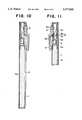
- FIG. 10is a longitudinal section of a modified example of the rodlike body feeding device of FIG. 2;
- FIG. 11is a longitudinal section showing a part of a rodlike body feeding device according to a second embodiment of the present invention.
- FIGS. 12 and 13are a front elevation and a side elevation, respectively, of a slider employed in the second embodiment of the rodlike body feeding device.
- FIGS. 14 and 15are a front elevation and a side elevation, respectively, of a slider of another embodiment.
- a flat surface portion 1ais formed on the outer surface of a tubular shaft 1, so that the flat surface portion 1a extends in the axial direction thereof.
- the flat surface portion 1ahas a slit 2 having on both sides thereof a plurality of mutually-facing pairs of locking portions 2a consisting of rectangular recesses.
- a slider 3which has a fastening portion 3a to which a rodlike body A, such as a lipstick, a crayon, a pastel, an eraser and a cutting blade is fixed.
- a rodlike body Asuch as a lipstick, a crayon, a pastel, an eraser and a cutting blade
- the part of the fastening portion 3a, to which the rodlike body A is fastened, which is on the opposite side of the locking portions 2a, and the part of a retraction preventing portion 3b, on which a projection 3d constituting locking means is formed, which is on the opposite side of the locking portions 2a,are connected to each other by an elastic platelike member 3e at a lower position of the platelike member.
- the part of the retraction preventing portion 3b which is close to the locking portions 2a, and the part of a slider body 3c which is close to the locking portions 2aare connected to each other by an elastic platelike member 3f at an upper position of the platelike member.
- spring member (for example, a leaf spring) 4has a locking portion 4a engageable with a locking portion 2a formed in the tubular shaft 1 and the spring member 4 is disposed in the interior of the retraction preventing portion 3b and slider body 3c so that the spring member 4 forms a "mountain" shape.
- the locking portion 4a of this spring member 4can be engaged with a locking portion 2a formed in the tubular shaft 1 through a hole 3g made in the central part of the platelike portion 3f by which the retraction preventing portion 3b and slider body 3c are connected together.
- a knob 5 of a clip 6is fixed to the slider body 3c at its leg portion 5a extending inward through the slit 2.
- the locking portion 4amay be a projection capable of entering a locking portion 2a, and, when the operability of the device during the feeding and retraction of the rodlike body A is taken into consideration, it is preferable that the locking portion 4a has a curved or inclined surface.
- the feeding-side surface (front surface) of the projection 3d constituting a locking portionis a curved or inclined surface, and that the retraction-side surface (rear surface) thereof is a substantially vertical surface when viewing the feeding device in the horizontal orientation shown in FIG. 5.
- the tubular shaft 1can employ any of other suitable cross-sectional shapes, such as a square or flat (oval) cross-sectional shape.
- FIG. 2which shows the device in a rest state
- the retraction preventing portion 3bdoes not receive any force from the fastening portion 3a and slider body 3c, so that the projection 3d constituting a locking portion is not in engagement with a locking portion 2a.
- the locking portion 4ais displaced toward the axis of the tubular shaft (i.e., in the radially inward direction of the tubular shaft) and disengaged from a locking portion 2a.
- the retraction preventing portion 3breceives only a force applied in one direction, so that the projection 3d constituting a locking portion does not engage a locking portion 2a.
- the retraction preventing portion 3breceives a compressive force from the fastening portion 3a and slider body 3c and is displaced radially outwardly, so that a locking portion 2a and the projection 3d are engaged with each other as shown in FIG. 5. This prevents the retraction of the rodlike body A during use of the feeding device.
- the reaction force described aboveis lost, and a pressure difference between the locking portion 2a of the tubular shaft 1 and the projection 3d constituting a locking portion is also lost. Consequently, the retraction preventing portion 3b returns to the original position and is disengaged from the locking portion 2a, so that the rodlike body A can be easily retracted into the tubular shaft 1.
- a platelike portion 3e of an elastic material for connecting a fastening portion 3a of a slider 3 and a retraction preventing portion 3b togetheris positioned close to the locking portions 2a
- a platelike portion 3f of an elastic material for connecting the retraction preventing portion 3b and a slider body 3c togetheris positioned on the opposite side of the locking portions 2a.
- both a platelike portion 3e of an elastic material for connecting a fastening portion 3a of a slider 3 and a retraction preventing portion 3b together, and a platelike portion 3f of an elastic material for connecting the retraction preventing portion 3b and a slider body 3c togetherare formed close to locking portions 2a. Accordingly, this modified example is identical with the first embodiment except that a projection 3d constituting a locking portion is formed on the substantially central part of the retraction preventing portion 3b, and the operation and effect of the modified example are identical with those of the first embodiment.
- FIG. 9Ashows still another modified example.
- a fastening portion 3a of a slider and a slider body 3care connected together by a retraction preventing portion 3b comprising an elastic plate member, and a projection 3d constituting a locking portion is formed on the substantially central part of this retraction preventing portion 3b.
- This modified exampleis identical with the above-described embodiment except that the retraction preventing portion 3b is so formed as to be curved arcuately and the projection 3d is formed outside the arcuately formed retraction preventing portion 3b.
- the operation and effect of this modified exampleare also substantially identical with those of the first embodiment.
- two retraction preventing portionsmay also be provided.
- the fastening portion 3a of the slider and the slider body 3care connected together at their lower parts by the retraction preventing portions 3b, and projections 3d constituting locking portions are formed on the substantially central parts of the lower sides of the retraction preventing portions 3b.
- the projections 3d constituting downwardly extending locking portionscontact the inner surface of the tubular shaft and generate frictional resistance, so that the retraction of a rodlike body A can be prevented more reliably.
- the projectionis not necessarily formed on the retraction preventing portions 3b.
- FIG. 10is a longitudinal section showing a modified example of the rodlike body feeding device of FIG. 2.
- a slit 2 and locking portions 2aconsisting of a plurality of holes are formed in a tubular shaft so that the slit 2 and locking portions 2a are positioned in a confronting relation with each other. Therefore, the construction, operation and effect of this modified example are identical with those of the first embodiment except that a knob 5 is provided on the opposite side of the locking portions 2a.
- the locking portionsmay be bores or recesses aligned longitudinally other than the illustrated examples.
- FIGS. 11-13A second embodiment of the present invention shown in FIGS. 11-13 will now be described.
- a slider 3is so formed that a retraction preventing portion 3b on which a projection 3d is formed is connected resiliently by a platelike portion 3e to a fastening portion 3a to which a rodlike body A if fastened, and a slider body 3c is joined resiliently to this retraction preventing portion 3b by a platelike portion 3f.
- a spring member 4 of a leaf spring having a locking portion 4a engageable with the locking portions 2a formed in a tubular shaft 1is provided in the interior of the slider body 3c in such a manner that the spring member 4 forms a "mountain" shape.
- the locking portion 4a of the spring member 4is projected from a window 3i provided in a side wall of the slide body 3c and engageable with a locking portion 2a in the tubular shaft 1, and the shoulder portions 4b of the spring member 4 contact the inner surface of the slider body 3c.
- a knob 5 of a clip 6is fixed at its leg portions 5a, extending downward through a slit 2 to the slider body 3c.
- the locking portion 4a of the spring member 4may be a projection capable of entering a locking portion 2a, and, when the operability of the device during the feeding and retraction of the rodlike body A is taken into consideration, it is preferable that the side surface of the locking portion 4a has a curved or inclined surface.
- the feeding (front) surface of the projection 3d constituting a locking portionhas a curved or inclined surface, and that the retraction-side (rear) surface thereof has a substantially vertical surface, in the same manner as in the previously-described embodiment.
- the retraction preventing portion 3breceives a compressive force from the fastening portion 3a and slider body 3c and is displaced radially outwardly, so that the locking portion 2a and the projection 3d constituting a locking portion are engaged with each other as shown in FIG. 5. This enables the retraction of the rodlike body A to be prevented.
- the locking portion 4a of the spring member 4When a pressing force is applied in the operating direction to the knob 5 fixed to the slider body 3c so as to slide the rodlike body A out or retract it, the locking portion 4a of the spring member 4 is displaced inwardly toward the axis of the tubular shaft (i.e., in the radially inward direction) against the elastic force of the spring member 4, so that the locking portion 4a is disengaged from a first locking portion 2a with which it is engaged and engages another locking portion 2a adjacent to the first locking portion 2a in accordance with the movement of the slider 3. During this time, the two shoulder portions 4b of the spring member 4 impinge upon the inner surface of the thick wall of the slider body 3c and generate light and pleasant click sounds. Therefore, the device can withstand-long-term use sufficiently.
- a platelike portion 3e extending rearwardly from a portion 3a, to which a rodlike body A is fastened, of a slider 3 and a retraction preventing portion 3b on which a projection 3d constituting a locking portion is formedare connected pivotally by connecting members 3h, such as bolts or screw, and this retraction preventing portion 3b and a slider body 3c are pivotally connected by a connecting portion 3f through connecting members 3j, 3k such as bolts or screws.
- the platelike portion 3e formed integrally with the fastening portion 3ais illustrated as an example, it can also be formed separately from the fastening portion 3a. When the platelike portion 3e is formed separately from the fastening portion 3a, they may be fixedly or pivotally connected together.
- the retraction preventing portion 3breceives a compressive force from the fastening portion 3a and slider body 3c and is displaced in the radially outward direction (vertically upward as shown in FIG. 15) to cause the locking portion 2a of the tubular shaft 1 and the projection 3d to be engaged with each other.
Landscapes
- Mechanical Pencils And Projecting And Retracting Systems Therefor, And Multi-System Writing Instruments (AREA)
Abstract
Description
This invention relates to a device for feeding a longitudinal rodlike body, such as a lipstick, a crayon, a pastel and an eraser, and more particularly to a rodlike body feeding device capable of extending and retracting a rodlike body from and into a case easily, and preventing the unintentional retraction of the rodlike body when in use.
Japanese Patent Publication No. 38239/1992 discloses a rodlike body feeding device consisting of a tubular shaft provided with a slit extending in the axial direction of the tubular shaft, and a plurality of engageable portions provided in the same axial direction; and a slider provided slidably in the tubular shaft and having a rodlike body-fastening portion.
This prior art publication is directed to a holder for a rodlike body, and the holder has a slider provided in the tubular shaft slidably in the axial direction, operable via a push-button, and fixable in an engagement position. The slider, mainly together with a tightening member, other than the push-button, constitutes a two-arm lever, and the two-arm lever can be turned around a common pivot. In order to convert a pressing force, which is exerted on a receiving member in the axial direction thereof, into a radially acting force and to transmit the converted force, the receiving member and the tightening member are movably connected via the above-mentioned pivot. The tubular shaft is provided with a tightened surface or a locking hole and a guide slit. The guide slit is so provided as to face to the tightened surface or locking hole. The object of adopting such a structure is to provide a holder for a rodlike member, the holder having a simple structure, such that, for example, the device can be easily operated by applying a pressure to the push-button in the axial and/or radial direction, and the rodlike member to be supported can be supported when an axial force is applied to the rodlike member.
However, in order to retract a rodlike body into the conventional rodlike body feeding device, it is necessary that the push-button (knob) be pressed radially inwardly toward the axis of the shaft (tube) and then moved in the axial direction while releasing the lock for preventing the retraction. Namely, the operability of this type of device needs improvement.
An object of the present invention is, in view of the complicated operation of the conventional device of this kind, to provide a rodlike body feeding device in which the rodlike body can be easily retracted, but which is not retracted during the use of the device.
Another object of the present invention is to provide an improved rodlike feeding body device capable of feeding a rodlike body comfortably with a light "click" sound even after the device has been used for a long time.
The present invention has been developed with a view to attaining these objects, and is directed to a rodlike body feeding device comprising a tubular shaft provided with a slit extending in the axial direction of the tubular shaft, and a plurality of locking portions arranged in the same axial direction, and a slider provided slidably in the tubular shaft and having a rodlike body fastening portion. The slider comprises a rodlike body fastening portion, a retraction preventing portion and a slider body in such a manner that the fastening portion and retraction preventing portion are connected with each other by an elastic body, and similarly the retraction preventing portion and slider body are connected with each other by an elastic member.
Since the rodlike fastening portion and retraction preventing portion are connected together, and the retraction preventing portion and slider body are connected together by the elastic members, respectively, the retraction preventing portion and the locking portions are not engaged while the rodlike body is being slid out or retracted, so that the feeding and retraction of the rodlike body can be accomplished by only the application of an axial force. When the device is in use, i.e., when the rodlike body is projected to a feedout position and pressed against, for example, the surface of paper, the retraction preventing portion receives a compressive force from the body fastening portion and slider body due to the reaction of the paper-pressing force, and is displaced toward the axis of the tubular shaft to be engaged with the locking portions thereof. Accordingly, unintentional retraction of the rodlike body can be prevented.
In another embodiment of the present invention, a rodlike body feeding device comprises a tubular shaft provided with a slit extending in the axial direction of the tubular shaft, and a plurality of locking portions provided in the same axial direction, and a slider provided slidably in the tubular shaft and having a rodlike body-fastening portion, and has a structure in which the slider comprises a rodlike body fastening portion, a retraction preventing portion connected elastically to the body fastening portion, and a tubular slider body connected elastically to the retraction preventing portion. A spring member is housed in the slider body in such a manner that the locking portion having a locking portion projects from a window provided in a side wall of the slider body, and is engaged with one of the above-mentioned locking portions.
By this structure, unintentional retraction of the rodlike body can be prevented, and, moreover, the shoulder portions of the spring member which are on the lower side of the locking portion thereof are in contact with the inner surface of the slider body since the spring member is housed in the slider body in a state that the locking portion projects from the window provided in the side wall of the slider body. When the rodlike body is projected or retracted, the locking portion of the spring member engages with and disengages from one of the locking portions of the tubular shaft continuously, so that the spring member is moved repeatedly in the radial, i.e. vertical direction. During this time, the shoulder portions of the spring member impinge upon the inner surface of the slider body to generate light click sounds, and the device can thus be operated comfortably. Since both shoulder portions of the spring member impinge upon the inner surface of the slider body, clear click sounds can be generated as compared with a case where only one shoulder portion impinges upon the inner surface. The part upon which the spring member impinges is the inner surface of the wall of the slider body which can be thickened, so that the device is durable for a long time.
In still another embodiment of the present invention, a rodlike body feeding device comprises a tubular shaft provide with a slit extending in the axial direction of the tubular shaft, and a plurality of locking portions provided in the same axial direction, and a slider provided slidably in the tubular shaft and having a rodlike body-fastening portion. In this embodiment of the invention, the slider comprises a rodlike body fastening portion, a retraction preventing portion connected pivotably to the body fastening portion, and a slider body connected pivotally to the retraction preventing portion.
By this arrangement, the retraction preventing portion and the locking portion of the tubular shaft are not engaged with each other during the rodlike body feeding and retraction operations, so that rodllke body can be fed out and retracted by applying an axial force only to the knob. When the device is in use, the retraction preventing portion receives a compressive force from the body fastening portion and slider body due to the reaction of the paper pressing force, and is displaced toward the axis of the tubular shaft to be engaged with a locking portion thereof. Accordingly, the retraction of the rodlike body can be prevented.
FIG. 1 is a front elevation of a rodlike body feeding device according to a first embodiment of the present invention;
FIG. 2 is a longitudinal section of the rodlike body feeding device shown in FIG. 1;
FIG. 3 and 4 are a front elevation and a side elevation, respectively, of a slider in the first embodiment;
FIG. 5 illustrates a retraction preventing mechanism shown in FIG. 2;
FIGS. 6 and 7 are a front elevation and a side elevation, respectively, of a slider in a modified example of the first embodiment;
FIGS. 8 and 9 are a front elevation and a side elevation, respectively, of a slider of another modified example of the first embodiment;
FIG. 9A is a side elevation of the slider of still another modified example;
FIG. 10 is a longitudinal section of a modified example of the rodlike body feeding device of FIG. 2;
FIG. 11 is a longitudinal section showing a part of a rodlike body feeding device according to a second embodiment of the present invention;
FIGS. 12 and 13 are a front elevation and a side elevation, respectively, of a slider employed in the second embodiment of the rodlike body feeding device; and
FIGS. 14 and 15 are a front elevation and a side elevation, respectively, of a slider of another embodiment.
Preferred embodiments of the present invention will now be described with reference to the drawings.
Referring to FIGS. 1-4, a flat surface portion 1a is formed on the outer surface of a tubular shaft 1, so that the flat surface portion 1a extends in the axial direction thereof. The flat surface portion 1a has aslit 2 having on both sides thereof a plurality of mutually-facing pairs of locking portions 2a consisting of rectangular recesses.
In the tubular shaft 1, slidably provided is aslider 3, which has a fasteningportion 3a to which a rodlike body A, such as a lipstick, a crayon, a pastel, an eraser and a cutting blade is fixed. In thisslider 3, the part of thefastening portion 3a, to which the rodlike body A is fastened, which is on the opposite side of the locking portions 2a, and the part of aretraction preventing portion 3b, on which aprojection 3d constituting locking means is formed, which is on the opposite side of the locking portions 2a, are connected to each other by an elasticplatelike member 3e at a lower position of the platelike member. The part of theretraction preventing portion 3b which is close to the locking portions 2a, and the part of aslider body 3c which is close to the locking portions 2a are connected to each other by an elasticplatelike member 3f at an upper position of the platelike member.
As shown in FIG. 5, spring member (for example, a leaf spring) 4 has alocking portion 4a engageable with a locking portion 2a formed in the tubular shaft 1 and thespring member 4 is disposed in the interior of theretraction preventing portion 3b andslider body 3c so that thespring member 4 forms a "mountain" shape. Thelocking portion 4a of thisspring member 4 can be engaged with a locking portion 2a formed in the tubular shaft 1 through ahole 3g made in the central part of theplatelike portion 3f by which theretraction preventing portion 3b andslider body 3c are connected together. Aknob 5 of aclip 6 is fixed to theslider body 3c at itsleg portion 5a extending inward through theslit 2.
Thelocking portion 4a may be a projection capable of entering a locking portion 2a, and, when the operability of the device during the feeding and retraction of the rodlike body A is taken into consideration, it is preferable that thelocking portion 4a has a curved or inclined surface. In view of the effect in preventing the retraction of the rodlike body A, it is preferable that the feeding-side surface (front surface) of theprojection 3d constituting a locking portion is a curved or inclined surface, and that the retraction-side surface (rear surface) thereof is a substantially vertical surface when viewing the feeding device in the horizontal orientation shown in FIG. 5. The tubular shaft 1 can employ any of other suitable cross-sectional shapes, such as a square or flat (oval) cross-sectional shape.
An operation of the device will now be described. Referring to FIG. 2 which shows the device in a rest state, theretraction preventing portion 3b does not receive any force from thefastening portion 3a andslider body 3c, so that theprojection 3d constituting a locking portion is not in engagement with a locking portion 2a. When a pressing force is applied to theknob 5 in the moving direction of the rodlike body A so as to feed or retract the rodlike body A, thelocking portion 4a is displaced toward the axis of the tubular shaft (i.e., in the radially inward direction of the tubular shaft) and disengaged from a locking portion 2a. During this time, theretraction preventing portion 3b receives only a force applied in one direction, so that theprojection 3d constituting a locking portion does not engage a locking portion 2a. When the device is in use, i.e., when the rodlike body A is projected outward and pressed on the surface of paper, the reaction force which is equal to the pressing force applied to the surface of the paper is exerted on the rodlike body A. Therefore, a force acting to retract the rodlike body A is exerted on theslider 3. However, since an engagement force of thelocking portion 4a with respect to a locking portion 2a is exerted on theslider body 3c, theretraction preventing portion 3b receives a compressive force from the fasteningportion 3a andslider body 3c and is displaced radially outwardly, so that a locking portion 2a and theprojection 3d are engaged with each other as shown in FIG. 5. This prevents the retraction of the rodlike body A during use of the feeding device. When the rodlike body A is displaced away from the surface of the paper after the device is used, the reaction force described above is lost, and a pressure difference between the locking portion 2a of the tubular shaft 1 and theprojection 3d constituting a locking portion is also lost. Consequently, theretraction preventing portion 3b returns to the original position and is disengaged from the locking portion 2a, so that the rodlike body A can be easily retracted into the tubular shaft 1.
Referring to FIGS. 6 and 7 showing a modified example of this embodiment, aplatelike portion 3e of an elastic material for connecting afastening portion 3a of aslider 3 and aretraction preventing portion 3b together is positioned close to the locking portions 2a, and aplatelike portion 3f of an elastic material for connecting theretraction preventing portion 3b and aslider body 3c together is positioned on the opposite side of the locking portions 2a. Accordingly, this modified example is identical with the previously-described embodiment except that aprojection 3d serving as a locking portion is formed on the part of theretraction preventing portion 3b which is near thefastening portion 3a, and the operation and effect of this modified example are also substantially identical with those of the previous embodiment.
Referring to FIGS. 8 and 9 which show another modified example, both aplatelike portion 3e of an elastic material for connecting afastening portion 3a of aslider 3 and aretraction preventing portion 3b together, and aplatelike portion 3f of an elastic material for connecting theretraction preventing portion 3b and aslider body 3c together are formed close to locking portions 2a. Accordingly, this modified example is identical with the first embodiment except that aprojection 3d constituting a locking portion is formed on the substantially central part of theretraction preventing portion 3b, and the operation and effect of the modified example are identical with those of the first embodiment.
FIG. 9A shows still another modified example.
In this modified example, afastening portion 3a of a slider and aslider body 3c are connected together by aretraction preventing portion 3b comprising an elastic plate member, and aprojection 3d constituting a locking portion is formed on the substantially central part of thisretraction preventing portion 3b. This modified example is identical with the above-described embodiment except that theretraction preventing portion 3b is so formed as to be curved arcuately and theprojection 3d is formed outside the arcuately formedretraction preventing portion 3b. The operation and effect of this modified example are also substantially identical with those of the first embodiment.
Although in the example shown in FIG. 9 only oneretraction preventing portion 3b is provided, two retraction preventing portions may also be provided. When two retraction preventing portions are provided, thefastening portion 3a of the slider and theslider body 3c are connected together at their lower parts by theretraction preventing portions 3b, andprojections 3d constituting locking portions are formed on the substantially central parts of the lower sides of theretraction preventing portions 3b. In this case theprojections 3d constituting downwardly extending locking portions contact the inner surface of the tubular shaft and generate frictional resistance, so that the retraction of a rodlike body A can be prevented more reliably. There are some cases where the retraction of a certain kind of rodlike body can be prevented to a certain extent even by only the friction between the retraction preventing portions and the inner surface of the tubular shaft. In such cases, the projection is not necessarily formed on theretraction preventing portions 3b.
FIG. 10 is a longitudinal section showing a modified example of the rodlike body feeding device of FIG. 2. In this modified example, aslit 2 and locking portions 2a consisting of a plurality of holes are formed in a tubular shaft so that theslit 2 and locking portions 2a are positioned in a confronting relation with each other. Therefore, the construction, operation and effect of this modified example are identical with those of the first embodiment except that aknob 5 is provided on the opposite side of the locking portions 2a. The locking portions may be bores or recesses aligned longitudinally other than the illustrated examples.
A second embodiment of the present invention shown in FIGS. 11-13 will now be described. In this embodiment, aslider 3 is so formed that aretraction preventing portion 3b on which aprojection 3d is formed is connected resiliently by aplatelike portion 3e to afastening portion 3a to which a rodlike body A if fastened, and aslider body 3c is joined resiliently to thisretraction preventing portion 3b by aplatelike portion 3f. Aspring member 4 of a leaf spring having a lockingportion 4a engageable with the locking portions 2a formed in a tubular shaft 1 is provided in the interior of theslider body 3c in such a manner that thespring member 4 forms a "mountain" shape. The lockingportion 4a of thespring member 4 is projected from awindow 3i provided in a side wall of theslide body 3c and engageable with a locking portion 2a in the tubular shaft 1, and theshoulder portions 4b of thespring member 4 contact the inner surface of theslider body 3c. Aknob 5 of aclip 6 is fixed at itsleg portions 5a, extending downward through aslit 2 to theslider body 3c.
As best shown in FIG. 13, the lockingportion 4a of thespring member 4 may be a projection capable of entering a locking portion 2a, and, when the operability of the device during the feeding and retraction of the rodlike body A is taken into consideration, it is preferable that the side surface of the lockingportion 4a has a curved or inclined surface. In view of the effect in preventing the retraction of the rodlike body A, it is preferable that the feeding (front) surface of theprojection 3d constituting a locking portion has a curved or inclined surface, and that the retraction-side (rear) surface thereof has a substantially vertical surface, in the same manner as in the previously-described embodiment.
Since an operation of the device in this embodiment is identical with that of the previously-described embodiment shown in, for example, FIG. 5, the detailed description thereof is omitted. When the device is in use, i.e., when the rodlike body A is projected outward and contacts the surface of paper, the reaction force which is equal to the pressing force applied to the surface of the paper is exerted on the rodlike body A. Therefore, a force for retracting the rodlike body A is exerted on theslider 3. However, since a force of engagement of the lockingportion 4a with a locking portion 2a is exerted on theslider body 3c, theretraction preventing portion 3b receives a compressive force from thefastening portion 3a andslider body 3c and is displaced radially outwardly, so that the locking portion 2a and theprojection 3d constituting a locking portion are engaged with each other as shown in FIG. 5. This enables the retraction of the rodlike body A to be prevented.
When a pressing force is applied in the operating direction to theknob 5 fixed to theslider body 3c so as to slide the rodlike body A out or retract it, the lockingportion 4a of thespring member 4 is displaced inwardly toward the axis of the tubular shaft (i.e., in the radially inward direction) against the elastic force of thespring member 4, so that the lockingportion 4a is disengaged from a first locking portion 2a with which it is engaged and engages another locking portion 2a adjacent to the first locking portion 2a in accordance with the movement of theslider 3. During this time, the twoshoulder portions 4b of thespring member 4 impinge upon the inner surface of the thick wall of theslider body 3c and generate light and pleasant click sounds. Therefore, the device can withstand-long-term use sufficiently.
Referring to FIGS. 14 and 15 which show another embodiment of the present invention, aplatelike portion 3e extending rearwardly from aportion 3a, to which a rodlike body A is fastened, of aslider 3 and aretraction preventing portion 3b on which aprojection 3d constituting a locking portion is formed are connected pivotally by connectingmembers 3h, such as bolts or screw, and thisretraction preventing portion 3b and aslider body 3c are pivotally connected by a connectingportion 3f through connectingmembers platelike portion 3e formed integrally with thefastening portion 3a is illustrated as an example, it can also be formed separately from thefastening portion 3a. When theplatelike portion 3e is formed separately from thefastening portion 3a, they may be fixedly or pivotally connected together.
Since the construction of the other parts of the feeding device in this embodiment are identical with that of the corresponding parts of the previously-described embodiments, the detailed description thereof will be omitted. An operation of the device in the embodiment of FIGS. 14 and 15 will now be briefly described.
When the device in this embodiment is in use with the rodlike body projected, a reaction force corresponding to the paper-pressing force is exerted on the rodlike body A, so that a force for retracting the rodlike body A is applied to theslider 3. A force due to the engagement of the lockingportion 4a of aspring member 4 with a locking portion 2a of the tubular shaft 1 is imparted to theslider body 3c. Accordingly, theretraction preventing portion 3b receives a compressive force from thefastening portion 3a andslider body 3c and is displaced in the radially outward direction (vertically upward as shown in FIG. 15) to cause the locking portion 2a of the tubular shaft 1 and theprojection 3d to be engaged with each other. This can prevent the retraction of the rodlike body A during use thereof. When the rodlike body A is displaced away from the surface of the paper after the device is used, the reaction force described above is lost, and a pressure difference between the locking portion 2a of the tubular shaft 1 and theprojection 3d constituting a locking portion is also lost. Consequently, theretraction preventing portion 3b returns to the original position and is disengaged from the locking portion 2a, so that the rodlike body A can be easily retracted into the tubular shaft 1. Since theplatelike portion 3e and connectingportion 3f can be formed separately, the material therefor can be selected freely. Therefore, the mechanical strength of the slider can be increased as necessary, and the device can be formed so as to withstand long-term use.
Claims (19)
1. A feeding device for feeding a rodlike body, comprising: a tubular member having a slit extending in the axial direction of the tubular member, and a plurality of locking portions arranged in the axial direction of the tubular member; and a slider disposed in the tubular member for sliding movement in the axial direction of the tubular member, the slider having a fastening portion for holding the rodlike body, a tubular slider body portion and a retraction preventing portion, the fastening portion and the retraction preventing portion being connected together by a first elastic portion, and the retraction preventing portion and the tubular slider body portion being connected together by a second elastic portion.
2. A feeding device for feeding a rodlike body, comprising: a tubular member having a slit extending in the axial direction of the tubular member, and a plurality of locking portions arranged in the axial direction of the tubular member; and a slider disposed in the tubular member for sliding movement in the axial direction of the tubular member, the slider having a fastening portion for holding the rodlike body, a retraction preventing portion elastically connected to the fastening portion, a tubular slider body portion elastically connected to the retraction preventing portion, and a spring member extending into the tubular slider body and having a locking portion, the locking portion of the spring member projecting from an opening provided in a side wall of the tubular slider body portion for engagement with one of the locking portions of the tubular member.
3. A feeding device for feeding a rodlike body, comprising: a tubular member having a slit extending in the axial direction of the tubular member, and a plurality of locking portions arranged in the axial direction of the tubular member; and a slider disposed in the tubular member for sliding movement in the axial direction of the tubular member, the slider having a fastening portion for holding the rodlike body, a slider body portion and a retraction preventing portion, the fastening portion and the retraction preventing portion being pivotally connected together, and the retraction preventing portion and the slider body portion being pivotally connected together.
4. A feeding device as claimed in claim 1; further comprising an operating member movable in the axial direction of the tubular member, the operating member being connected to the slider for sliding the slider during movement of the operating member in only the axial direction of the tubular member.
5. A feeding device as claimed in claim 4; wherein the operating member is fixed to the tubular slider body portion of the slider.
6. A feeding device as claimed in claim 4; further comprising a spring member disposed in the tubular member and in engagement with the slider, the spring member having a locking portion for engagement with the locking portions of the tubular member when the operating member slides the slider in the axial direction of the tubular member.
7. A feeding device as claimed in claim 1; wherein the retraction preventing portion of the slider has a projection for engagement with the locking portions of the tubular member upon application of a compressive force on the rodlike body in the axial direction of the tubular member.
8. A feeding device as claimed 7; further comprising a spring member disposed in the tubular member and in engagement with the slider, the spring member having a locking portion for engagement with the locking portions of the tubular member during sliding movement of the slider in the axial direction of the tubular member.
9. A feeding device as claimed in claim 8; wherein the spring member has a first leg portion engaging the tubular slider body, and a second leg portion engaging the retraction preventing portion.
10. A feeding device as claimed in claim 9; wherein the second elastic portion of the slider has an opening, and the locking portion of the spring member extends through said opening.
11. A feeding device for feeding a body, comprising: a tubular member having a plurality of locking portions arranged in the axial direction of the tubular member; a slider disposed in the tubular member for sliding movement in first and second directions along the axial direction of the tubular member, the slider having a fastening portion for holding a body to be fed, a projection for engagement with the locking portions of the tubular member only upon application of a force on the body tending to slide the slider in the second direction, a slider body portion, an intermediate body portion supporting the projection, a first elastic portion connecting the fastening portion to the intermediate body portion, and a second elastic portion connecting the slider body portion to the intermediate body portion; and a spring member disposed in the tubular member and engaging the slider, the spring member having a locking portion for engagement with the locking portions of the tubular member during sliding movement of the slider in the first and second directions.
12. A feeding device as claimed in claim 11; wherein the spring member has a first leg portion and a second leg portion, the first leg portion engaging the intermediate body portion of the slider, and the second leg portion engaging the slider body portion of the slider.
13. A feeding device as claimed in claim 12; wherein the second elastic portion of the slider has an opening, and the locking portion of the spring member extends through the opening.
14. A feeding device as claimed in claim 12; wherein the slider body portion has an opening, and the locking portion of the spring member extends through the opening.
15. A feeding device as claimed in claim 11; wherein the projection of the slider is disposed closer to the second elastic portion than to the first elastic portion.
16. A feeding device as claimed in claim 11; wherein the projection of the slider is disposed closer to the first elastic portion than to the second elastic portion.
17. A feeding device as claimed in claim 11; wherein the slider is of one-piece construction.
18. A feeding device as claimed in 11; wherein the first and second elastic portions of the slider are pivotally connected to the respective fastening portion, intermediate body portion and slider body portion of the slider.
19. A feeding device as claimed in claim 11; further comprising an operating member movable in the axial direction of the tubular member, the operating member being connected to the slider for sliding the slider between the first and second directions during movement of the operating member only in the axial direction of the tubular member.
Applications Claiming Priority (7)
| Application Number | Priority Date | Filing Date | Title |
|---|---|---|---|
| JP5957192 | 1992-07-31 | ||
| JP4-059571U | 1992-07-31 | ||
| JP5-013183U | 1993-02-26 | ||
| JP1318393 | 1993-02-26 | ||
| JP5-041265U | 1993-06-30 | ||
| JP4126593 | 1993-06-30 | ||
| PCT/JP1993/001054WO2004098903A1 (en) | 1992-07-31 | 1993-07-27 | Apparatus for extending rod type materials |
Publications (1)
| Publication Number | Publication Date |
|---|---|
| US5577850Atrue US5577850A (en) | 1996-11-26 |
Family
ID=27280149
Family Applications (1)
| Application Number | Title | Priority Date | Filing Date |
|---|---|---|---|
| US08/211,464Expired - LifetimeUS5577850A (en) | 1992-07-31 | 1993-07-27 | Rodlike body feeding device |
Country Status (2)
| Country | Link |
|---|---|
| US (1) | US5577850A (en) |
| WO (1) | WO2004098903A1 (en) |
Cited By (25)
| Publication number | Priority date | Publication date | Assignee | Title |
|---|---|---|---|---|
| USD425122S (en)* | 1999-01-18 | 2000-05-16 | Manufacture D'articles De Precision Et De Dessin-M.A.P.E.D. | Eraser |
| US6123476A (en)* | 1999-10-28 | 2000-09-26 | Rosenthal; Donald M. | Crayon holder with integral sharpener |
| US6290413B1 (en)* | 2000-10-24 | 2001-09-18 | Wen-Yi Wang | Writing instrument |
| US6547465B1 (en) | 2002-01-22 | 2003-04-15 | Shoot The Moon Products Ii, Llc | Pencil with exposable eraser |
| US20030233098A1 (en)* | 2002-06-18 | 2003-12-18 | Stryker Spine | Variable depth drill guide |
| US6695511B2 (en) | 2002-06-17 | 2004-02-24 | St. Louis Crayon & Soapstone, Inc. | Soapstone holder |
| USD496730S1 (en) | 2003-03-17 | 2004-09-28 | Becton, Dickinson & Company | Surgical knife safety handle |
| US20040215174A1 (en)* | 2003-04-22 | 2004-10-28 | Morawski Michael J. | Surgical knife safety handle |
| US20050015104A1 (en)* | 2003-04-22 | 2005-01-20 | Morawski Michael J. | Surgical knife safety handle |
| US20070005088A1 (en)* | 2005-04-29 | 2007-01-04 | Lehuec Jean-Charles | Implantation of a deformable prosthesic device |
| USD571010S1 (en) | 2006-10-17 | 2008-06-10 | Becton, Dickinson And Company | Surgical knife safety handle |
| US7596974B2 (en) | 2006-06-19 | 2009-10-06 | S.C. Johnson & Son, Inc. | Instant stain removing device, formulation and absorbent means |
| USD604768S1 (en)* | 2008-04-18 | 2009-11-24 | Sakura Color Products Corporation | Marker holder |
| US20100272495A1 (en)* | 2007-12-10 | 2010-10-28 | De Novo S.R.O. | Chalk holder with a resilient latch element |
| USD631915S1 (en)* | 2008-11-19 | 2011-02-01 | Faber-Castell Aktiengesellschaft | Eraser |
| US7909840B2 (en) | 2004-10-20 | 2011-03-22 | Beaver-Visitec International (Us), Inc. | Surgical knife safety handle having user operable lock |
| US20110098734A1 (en)* | 2008-02-07 | 2011-04-28 | Dana Michael Cote | Retractable safety knife |
| USD685428S1 (en)* | 2011-08-25 | 2013-07-02 | Beifa Group Co., Ltd. | Eraser |
| USD714386S1 (en)* | 2013-08-14 | 2014-09-30 | Lai On Products (Industrial) Limited | Crayon holder |
| USD728025S1 (en)* | 2013-06-21 | 2015-04-28 | F.I.L.A.—Fabbrica Italiana Lapis Ed Affini S.p.A. | Marker |
| US20160000541A1 (en)* | 2013-10-25 | 2016-01-07 | Zee Zee Corporation | Method of using a bristled toothpick assembly |
| USD752146S1 (en) | 2015-01-14 | 2016-03-22 | F. I. L. A.—Fabbrica Italiana Lapis Ed Affini S.P.A. | Marker |
| US10398808B2 (en)* | 2006-10-13 | 2019-09-03 | Kci Licensing, Inc. | Reduced pressure delivery system having a manually-activated pump for providing treatment to low-severity wounds |
| USD865869S1 (en)* | 2017-06-20 | 2019-11-05 | Pentel Kabushiki Kaisha | Marking pen |
| USD895013S1 (en)* | 2017-12-01 | 2020-09-01 | Mproved Ideas, LLC | Eraser assembly |
Citations (10)
| Publication number | Priority date | Publication date | Assignee | Title |
|---|---|---|---|---|
| US1097238A (en)* | 1912-10-11 | 1914-05-19 | William H Krell | Pencil. |
| DE582484C (en)* | 1928-10-09 | 1933-08-16 | Albert Kann Dr | Pencil holder |
| US2259133A (en)* | 1940-05-11 | 1941-10-14 | Elmer E Harper | Mechanical instrument holder device |
| US2314777A (en)* | 1940-08-17 | 1943-03-23 | Farrington Hastings Macleod | Mechanical pencil |
| US3756727A (en)* | 1971-12-01 | 1973-09-04 | Maitlen & Benson Inc | Holder for marking material |
| JPS4898238A (en)* | 1972-03-29 | 1973-12-13 | ||
| JPS5024245A (en)* | 1973-07-02 | 1975-03-15 | ||
| JPS6331992A (en)* | 1986-07-25 | 1988-02-10 | 石川島播磨重工業株式会社 | container crane |
| JPH0423036A (en)* | 1990-05-18 | 1992-01-27 | Fujitsu Ltd | How to specify software startup conditions |
| JPH0438239A (en)* | 1990-05-30 | 1992-02-07 | Nissan Motor Co Ltd | Glove box opening/closing device |
Family Cites Families (4)
| Publication number | Priority date | Publication date | Assignee | Title |
|---|---|---|---|---|
| JPS4898238U (en)* | 1972-02-21 | 1973-11-20 | ||
| JPS5024245U (en)* | 1973-06-28 | 1975-03-19 | ||
| JPS5968999U (en)* | 1982-10-29 | 1984-05-10 | ぺんてる株式会社 | eraser holder |
| JPH0423036Y2 (en)* | 1986-06-19 | 1992-05-27 |
- 1993
- 1993-07-27USUS08/211,464patent/US5577850A/ennot_activeExpired - Lifetime
- 1993-07-27WOPCT/JP1993/001054patent/WO2004098903A1/enactiveApplication Filing
Patent Citations (10)
| Publication number | Priority date | Publication date | Assignee | Title |
|---|---|---|---|---|
| US1097238A (en)* | 1912-10-11 | 1914-05-19 | William H Krell | Pencil. |
| DE582484C (en)* | 1928-10-09 | 1933-08-16 | Albert Kann Dr | Pencil holder |
| US2259133A (en)* | 1940-05-11 | 1941-10-14 | Elmer E Harper | Mechanical instrument holder device |
| US2314777A (en)* | 1940-08-17 | 1943-03-23 | Farrington Hastings Macleod | Mechanical pencil |
| US3756727A (en)* | 1971-12-01 | 1973-09-04 | Maitlen & Benson Inc | Holder for marking material |
| JPS4898238A (en)* | 1972-03-29 | 1973-12-13 | ||
| JPS5024245A (en)* | 1973-07-02 | 1975-03-15 | ||
| JPS6331992A (en)* | 1986-07-25 | 1988-02-10 | 石川島播磨重工業株式会社 | container crane |
| JPH0423036A (en)* | 1990-05-18 | 1992-01-27 | Fujitsu Ltd | How to specify software startup conditions |
| JPH0438239A (en)* | 1990-05-30 | 1992-02-07 | Nissan Motor Co Ltd | Glove box opening/closing device |
Cited By (50)
| Publication number | Priority date | Publication date | Assignee | Title |
|---|---|---|---|---|
| USD425122S (en)* | 1999-01-18 | 2000-05-16 | Manufacture D'articles De Precision Et De Dessin-M.A.P.E.D. | Eraser |
| US6123476A (en)* | 1999-10-28 | 2000-09-26 | Rosenthal; Donald M. | Crayon holder with integral sharpener |
| US6290413B1 (en)* | 2000-10-24 | 2001-09-18 | Wen-Yi Wang | Writing instrument |
| US6547465B1 (en) | 2002-01-22 | 2003-04-15 | Shoot The Moon Products Ii, Llc | Pencil with exposable eraser |
| US6695511B2 (en) | 2002-06-17 | 2004-02-24 | St. Louis Crayon & Soapstone, Inc. | Soapstone holder |
| AU2003204795B2 (en)* | 2002-06-18 | 2008-12-11 | Stryker European Holdings I, Llc | Variable depth drill guide |
| US20030233098A1 (en)* | 2002-06-18 | 2003-12-18 | Stryker Spine | Variable depth drill guide |
| USD496730S1 (en) | 2003-03-17 | 2004-09-28 | Becton, Dickinson & Company | Surgical knife safety handle |
| US20050015104A1 (en)* | 2003-04-22 | 2005-01-20 | Morawski Michael J. | Surgical knife safety handle |
| US7022128B2 (en) | 2003-04-22 | 2006-04-04 | Becton, Dickinson And Company | Surgical knife safety handle |
| US10258367B2 (en) | 2003-04-22 | 2019-04-16 | Beaver-Visitec International (Us), Inc. | Surgical knife safety handle |
| US20080058843A1 (en)* | 2003-04-22 | 2008-03-06 | Morawski Michael J | Surgical knife safety handle |
| US10271872B2 (en) | 2003-04-22 | 2019-04-30 | Beaver-Visitec International (Us), Inc. | Surgical knife safety handle |
| US7387637B2 (en) | 2003-04-22 | 2008-06-17 | Becton, Dickinson And Company | Surgical knife safety handle |
| US7901422B2 (en) | 2003-04-22 | 2011-03-08 | Beaver-Visitec International (Us), Inc. | Surgical knife safety handle |
| USD685091S1 (en) | 2003-04-22 | 2013-06-25 | Beaver-Vistec International (US), Inc. | Surgical knife safety handle guard |
| USD685092S1 (en) | 2003-04-22 | 2013-06-25 | Beaver-Visitec International (Us), Inc. | Surgical knife safety handle |
| US20040215174A1 (en)* | 2003-04-22 | 2004-10-28 | Morawski Michael J. | Surgical knife safety handle |
| US7905894B2 (en) | 2003-04-22 | 2011-03-15 | Beaver-Visitec International (Us), Inc. | Surgical knife safety handle |
| US12161361B2 (en) | 2004-10-20 | 2024-12-10 | Beaver-Visitec International (Us), Inc. | Surgical knife safety handle having user operable lock |
| US11779368B2 (en) | 2004-10-20 | 2023-10-10 | Beaver-Visitec International (Us), Inc. | Surgical knife safety handle having user operable lock |
| US7909840B2 (en) | 2004-10-20 | 2011-03-22 | Beaver-Visitec International (Us), Inc. | Surgical knife safety handle having user operable lock |
| US11109886B2 (en) | 2004-10-20 | 2021-09-07 | Beaver-Visitec International (Us), Inc. | Surgical knife safety handle having user operable lock |
| US9480495B2 (en) | 2004-10-20 | 2016-11-01 | Beaver-Visitec International (Us), Inc. | Surgical knife safety handle having user operable lock |
| US8814893B2 (en) | 2004-10-20 | 2014-08-26 | Beaver-Visitec International (Us), Inc. | Surgical knife safety handle having user operable lock |
| US10357279B2 (en) | 2004-10-20 | 2019-07-23 | Beaver-Visitec International (Us), Inc. | Surgical knife safety handle having user operable lock |
| US7828807B2 (en)* | 2005-04-29 | 2010-11-09 | Warsaw Orthopedic, Inc. | Implantation of a deformable prosthesic device |
| US20070005088A1 (en)* | 2005-04-29 | 2007-01-04 | Lehuec Jean-Charles | Implantation of a deformable prosthesic device |
| US7596974B2 (en) | 2006-06-19 | 2009-10-06 | S.C. Johnson & Son, Inc. | Instant stain removing device, formulation and absorbent means |
| US10398808B2 (en)* | 2006-10-13 | 2019-09-03 | Kci Licensing, Inc. | Reduced pressure delivery system having a manually-activated pump for providing treatment to low-severity wounds |
| USD571010S1 (en) | 2006-10-17 | 2008-06-10 | Becton, Dickinson And Company | Surgical knife safety handle |
| US20100272495A1 (en)* | 2007-12-10 | 2010-10-28 | De Novo S.R.O. | Chalk holder with a resilient latch element |
| US20110098734A1 (en)* | 2008-02-07 | 2011-04-28 | Dana Michael Cote | Retractable safety knife |
| US9044265B2 (en)* | 2008-02-07 | 2015-06-02 | Beaver-Visitec International (Us), Inc. | Retractable safety knife |
| US8464430B2 (en) | 2008-02-07 | 2013-06-18 | Beaver-Visitec International (Us), Inc. | Retractable safety knife |
| USD604768S1 (en)* | 2008-04-18 | 2009-11-24 | Sakura Color Products Corporation | Marker holder |
| USD631915S1 (en)* | 2008-11-19 | 2011-02-01 | Faber-Castell Aktiengesellschaft | Eraser |
| USD685428S1 (en)* | 2011-08-25 | 2013-07-02 | Beifa Group Co., Ltd. | Eraser |
| USD728025S1 (en)* | 2013-06-21 | 2015-04-28 | F.I.L.A.—Fabbrica Italiana Lapis Ed Affini S.p.A. | Marker |
| USD753225S1 (en) | 2013-06-21 | 2016-04-05 | F.I.L.A.—Fabrica Italiana Lapis Ed Affini S.p.A. | Cap of a marker |
| USD751643S1 (en) | 2013-06-21 | 2016-03-15 | F.I.L.A.—Fabbrica Italiana Lapis Ed Affini S.p.A. | Marker |
| USD751145S1 (en) | 2013-06-21 | 2016-03-08 | F.I.L.A.—Fabrica Italiana Lapis Ed Affini S.p.A. | Marker |
| USD746377S1 (en)* | 2013-08-14 | 2015-12-29 | Lai On Products (Industrial) Limited | Crayon holder |
| USD714386S1 (en)* | 2013-08-14 | 2014-09-30 | Lai On Products (Industrial) Limited | Crayon holder |
| US10231808B2 (en)* | 2013-10-25 | 2019-03-19 | Zee Zee Corporation | Method of using a bristled toothpick assembly |
| US20160000541A1 (en)* | 2013-10-25 | 2016-01-07 | Zee Zee Corporation | Method of using a bristled toothpick assembly |
| USD752146S1 (en) | 2015-01-14 | 2016-03-22 | F. I. L. A.—Fabbrica Italiana Lapis Ed Affini S.P.A. | Marker |
| USD865869S1 (en)* | 2017-06-20 | 2019-11-05 | Pentel Kabushiki Kaisha | Marking pen |
| USD876540S1 (en) | 2017-06-20 | 2020-02-25 | Pentel Kabushiki Kaisha | Marking pen |
| USD895013S1 (en)* | 2017-12-01 | 2020-09-01 | Mproved Ideas, LLC | Eraser assembly |
Also Published As
| Publication number | Publication date |
|---|---|
| WO2004098903A1 (en) | 2004-11-18 |
Similar Documents
| Publication | Publication Date | Title |
|---|---|---|
| US5577850A (en) | Rodlike body feeding device | |
| US20070017100A1 (en) | Utility knife with quick release housing | |
| GR930300069T1 (en) | Cigarette lighter. | |
| HU216862B (en) | Hand-operated stamping device | |
| US3947133A (en) | Automatic pencil | |
| US7493838B2 (en) | Multi-bit screwdriver | |
| US5074694A (en) | Latch mechanism for retractable writing instruments | |
| US4106874A (en) | Mechanical pencil | |
| US20200232752A1 (en) | Device for positioning a stock portion on a gunstock and gunstock comprising such a device | |
| US4714365A (en) | Mechanical pencil | |
| US4459057A (en) | Mechanical pencil with automatic lead advance | |
| US20070231048A1 (en) | Writing Instrument With a Lateral Button | |
| US5020836A (en) | Easily openable tubular latch | |
| JP2607154Y2 (en) | Rod feeding device | |
| US6203226B1 (en) | Side-knock type mechanical pencil | |
| US4650359A (en) | Mechanical pencil with automatic lead advance | |
| US6082916A (en) | Mechanical pencil | |
| JPH0438239B2 (en) | ||
| US5462376A (en) | Mechanical pencil with improved slider mechanism | |
| JP3938791B2 (en) | Writing utensils | |
| US4571105A (en) | Lead engaging chuck mechanism for mechanical pencil | |
| US3439989A (en) | Automatic pencil | |
| GB2256619A (en) | Mechanical pencil with lead-feeding device preventing unintended lead feed. | |
| US2800882A (en) | Latch means for retractable ball pens | |
| JP2601606B2 (en) | Structure of holder for blade-retractable cutter knife |
Legal Events
| Date | Code | Title | Description |
|---|---|---|---|
| AS | Assignment | Owner name:PENTEL KABUSHIKI KAISHA, JAPAN Free format text:ASSIGNMENT OF ASSIGNORS INTEREST;ASSIGNOR:MISHIMA, SHINGO;REEL/FRAME:007299/0741 Effective date:19940301 | |
| AS | Assignment | Owner name:PENTEL KABUSHIKI KAISHA, JAPAN Free format text:RECORDAL OF CORRECTED ASSIGNEE'S ADDRESS IN A DOCUMENT PREVIOUSLY RECORDED ON REEL 7299 FRAME 0741;ASSIGNOR:MISHIMA, SHINGO;REEL/FRAME:007853/0355 Effective date:19940301 | |
| STCF | Information on status: patent grant | Free format text:PATENTED CASE | |
| FEPP | Fee payment procedure | Free format text:PAYOR NUMBER ASSIGNED (ORIGINAL EVENT CODE: ASPN); ENTITY STATUS OF PATENT OWNER: LARGE ENTITY | |
| FPAY | Fee payment | Year of fee payment:4 | |
| FPAY | Fee payment | Year of fee payment:8 | |
| REMI | Maintenance fee reminder mailed | ||
| FPAY | Fee payment | Year of fee payment:12 | |
| SULP | Surcharge for late payment | Year of fee payment:11 |