US5577363A - Structural panel - Google Patents
Structural panelDownload PDFInfo
- Publication number
- US5577363A US5577363AUS08/392,574US39257495AUS5577363AUS 5577363 AUS5577363 AUS 5577363AUS 39257495 AUS39257495 AUS 39257495AUS 5577363 AUS5577363 AUS 5577363A
- Authority
- US
- United States
- Prior art keywords
- sheet
- sheets
- foam
- separation space
- edge
- Prior art date
- Legal status (The legal status is an assumption and is not a legal conclusion. Google has not performed a legal analysis and makes no representation as to the accuracy of the status listed.)
- Expired - Fee Related
Links
- 239000006260foamSubstances0.000claimsabstractdescription41
- 238000000926separation methodMethods0.000claimsabstractdescription30
- 239000008258liquid foamSubstances0.000claimsabstractdescription14
- 238000004519manufacturing processMethods0.000claimsabstractdescription9
- 239000007788liquidSubstances0.000claimsdescription7
- 230000004888barrier functionEffects0.000claimsdescription6
- 238000009432framingMethods0.000claimsdescription4
- 230000000903blocking effectEffects0.000claimsdescription2
- 230000002093peripheral effectEffects0.000claimsdescription2
- 238000009877renderingMethods0.000claimsdescription2
- 238000000034methodMethods0.000abstractdescription9
- 238000010079rubber tappingMethods0.000abstractdescription2
- 239000000463materialSubstances0.000description4
- 238000004026adhesive bondingMethods0.000description3
- 239000008259solid foamSubstances0.000description3
- 239000003677Sheet moulding compoundSubstances0.000description2
- 239000000853adhesiveSubstances0.000description2
- 230000001070adhesive effectEffects0.000description2
- XAGFODPZIPBFFR-UHFFFAOYSA-NaluminiumChemical compound[Al]XAGFODPZIPBFFR-UHFFFAOYSA-N0.000description2
- 229910052782aluminiumInorganic materials0.000description2
- 230000006835compressionEffects0.000description2
- 238000007906compressionMethods0.000description2
- 229920001187thermosetting polymerPolymers0.000description2
- 239000002023woodSubstances0.000description2
- 229910000831SteelInorganic materials0.000description1
- 238000000071blow mouldingMethods0.000description1
- 238000000748compression mouldingMethods0.000description1
- 239000004794expanded polystyreneSubstances0.000description1
- 238000001125extrusionMethods0.000description1
- 238000005429filling processMethods0.000description1
- 238000001746injection mouldingMethods0.000description1
- 238000012986modificationMethods0.000description1
- 230000004048modificationEffects0.000description1
- 239000002991molded plasticSubstances0.000description1
- 239000004033plasticSubstances0.000description1
- 229920003023plasticPolymers0.000description1
- 229920002635polyurethanePolymers0.000description1
- 239000004814polyurethaneSubstances0.000description1
- 238000010107reaction injection mouldingMethods0.000description1
- 239000010959steelSubstances0.000description1
- 238000003856thermoformingMethods0.000description1
- 229920001169thermoplasticPolymers0.000description1
- 239000004416thermosoftening plasticSubstances0.000description1
- 238000007666vacuum formingMethods0.000description1
Images


Classifications
- B—PERFORMING OPERATIONS; TRANSPORTING
- B29—WORKING OF PLASTICS; WORKING OF SUBSTANCES IN A PLASTIC STATE IN GENERAL
- B29C—SHAPING OR JOINING OF PLASTICS; SHAPING OF MATERIAL IN A PLASTIC STATE, NOT OTHERWISE PROVIDED FOR; AFTER-TREATMENT OF THE SHAPED PRODUCTS, e.g. REPAIRING
- B29C44/00—Shaping by internal pressure generated in the material, e.g. swelling or foaming ; Producing porous or cellular expanded plastics articles
- B29C44/02—Shaping by internal pressure generated in the material, e.g. swelling or foaming ; Producing porous or cellular expanded plastics articles for articles of definite length, i.e. discrete articles
- B29C44/12—Incorporating or moulding on preformed parts, e.g. inserts or reinforcements
- B29C44/1228—Joining preformed parts by the expanding material
- B29C44/1233—Joining preformed parts by the expanding material the preformed parts being supported during expanding
- E—FIXED CONSTRUCTIONS
- E04—BUILDING
- E04C—STRUCTURAL ELEMENTS; BUILDING MATERIALS
- E04C2/00—Building elements of relatively thin form for the construction of parts of buildings, e.g. sheet materials, slabs, or panels
- E04C2/30—Building elements of relatively thin form for the construction of parts of buildings, e.g. sheet materials, slabs, or panels characterised by the shape or structure
- E04C2/38—Building elements of relatively thin form for the construction of parts of buildings, e.g. sheet materials, slabs, or panels characterised by the shape or structure with attached ribs, flanges, or the like, e.g. framed panels
- E04C2/386—Building elements of relatively thin form for the construction of parts of buildings, e.g. sheet materials, slabs, or panels characterised by the shape or structure with attached ribs, flanges, or the like, e.g. framed panels with a frame of unreconstituted or laminated wood
- E—FIXED CONSTRUCTIONS
- E06—DOORS, WINDOWS, SHUTTERS, OR ROLLER BLINDS IN GENERAL; LADDERS
- E06B—FIXED OR MOVABLE CLOSURES FOR OPENINGS IN BUILDINGS, VEHICLES, FENCES OR LIKE ENCLOSURES IN GENERAL, e.g. DOORS, WINDOWS, BLINDS, GATES
- E06B3/00—Window sashes, door leaves, or like elements for closing wall or like openings; Layout of fixed or moving closures, e.g. windows in wall or like openings; Features of rigidly-mounted outer frames relating to the mounting of wing frames
- E06B3/54—Fixing of glass panes or like plates
- E06B3/58—Fixing of glass panes or like plates by means of borders, cleats, or the like
- E06B3/5892—Fixing of window panes in openings in door leaves
- E—FIXED CONSTRUCTIONS
- E06—DOORS, WINDOWS, SHUTTERS, OR ROLLER BLINDS IN GENERAL; LADDERS
- E06B—FIXED OR MOVABLE CLOSURES FOR OPENINGS IN BUILDINGS, VEHICLES, FENCES OR LIKE ENCLOSURES IN GENERAL, e.g. DOORS, WINDOWS, BLINDS, GATES
- E06B3/00—Window sashes, door leaves, or like elements for closing wall or like openings; Layout of fixed or moving closures, e.g. windows in wall or like openings; Features of rigidly-mounted outer frames relating to the mounting of wing frames
- E06B3/70—Door leaves
- E06B3/7001—Coverings therefor; Door leaves imitating traditional raised panel doors, e.g. engraved or embossed surfaces, with trim strips applied to the surfaces
- E—FIXED CONSTRUCTIONS
- E06—DOORS, WINDOWS, SHUTTERS, OR ROLLER BLINDS IN GENERAL; LADDERS
- E06B—FIXED OR MOVABLE CLOSURES FOR OPENINGS IN BUILDINGS, VEHICLES, FENCES OR LIKE ENCLOSURES IN GENERAL, e.g. DOORS, WINDOWS, BLINDS, GATES
- E06B3/00—Window sashes, door leaves, or like elements for closing wall or like openings; Layout of fixed or moving closures, e.g. windows in wall or like openings; Features of rigidly-mounted outer frames relating to the mounting of wing frames
- E06B3/70—Door leaves
- E06B3/72—Door leaves consisting of frame and panels, e.g. of raised panel type
- E06B3/78—Door leaves consisting of frame and panels, e.g. of raised panel type with panels of plastics
- E—FIXED CONSTRUCTIONS
- E06—DOORS, WINDOWS, SHUTTERS, OR ROLLER BLINDS IN GENERAL; LADDERS
- E06B—FIXED OR MOVABLE CLOSURES FOR OPENINGS IN BUILDINGS, VEHICLES, FENCES OR LIKE ENCLOSURES IN GENERAL, e.g. DOORS, WINDOWS, BLINDS, GATES
- E06B3/00—Window sashes, door leaves, or like elements for closing wall or like openings; Layout of fixed or moving closures, e.g. windows in wall or like openings; Features of rigidly-mounted outer frames relating to the mounting of wing frames
- E06B3/70—Door leaves
- E06B3/82—Flush doors, i.e. with completely flat surface
- E06B3/822—Flush doors, i.e. with completely flat surface with an internal foursided frame
- E—FIXED CONSTRUCTIONS
- E06—DOORS, WINDOWS, SHUTTERS, OR ROLLER BLINDS IN GENERAL; LADDERS
- E06B—FIXED OR MOVABLE CLOSURES FOR OPENINGS IN BUILDINGS, VEHICLES, FENCES OR LIKE ENCLOSURES IN GENERAL, e.g. DOORS, WINDOWS, BLINDS, GATES
- E06B3/00—Window sashes, door leaves, or like elements for closing wall or like openings; Layout of fixed or moving closures, e.g. windows in wall or like openings; Features of rigidly-mounted outer frames relating to the mounting of wing frames
- E06B3/70—Door leaves
- E06B3/7015—Door leaves characterised by the filling between two external panels
- E06B2003/7023—Door leaves characterised by the filling between two external panels of foam type
Definitions
- the inventionrelates to doors and other structural panels formed from two sheets separated by a frame, sometimes with a foam or other core between the sheets.
- the space between the sheetsis filled with foam in a liquid state, which then hardens into a solid foam core.
- foamin a liquid state, which then hardens into a solid foam core.
- the liquid foamtends to leak into the window frame area, which necessitates clean up work, which increases manufacturing costs. There is therefore a need to control the flow of the foam in order to minimize such leakage.
- the solid foam corecan provide sufficient structural integrity so that framing members would not be needed on all sides, except for the need to provide an enclosed chamber into which to introduce the liquid foam. There is a need for a way to introduce the foam without using unnecessary framing members which add weight and cost.
- the present inventionis directed to a door or other structural panel that satisfies these needs.
- the inventionprovides a structural panel which comprises a pair of opposed, congruent sheets which are spaced apart by a frame to form a separation space between them.
- the frameincludes a beam located longitudinally along an edge of each of the sheets.
- Each sheethas an outer side and an inner side facing the inner side of the other sheet.
- the edge of each of the sheetshas an inwardly projecting zig-zag which defines a ledge on the outer side of the sheet and a ridge on the inner side of the sheet.
- a flangeextends from the beam.
- the flangehas a connected leg which is an extension of the beam and is outward of the ledge.
- the flangealso has a free leg overlying the ledge.
- a hookprojects from the beam into the separation space.
- the hookincludes a post which projects inwardly from the beam inward of the ledge and a cross member which projects outwardly from the post inward of the ridge toward the inner side of the sheet.
- the sheet and the beamare adapted so that the ledge fits closely between the flange and the hook thereby establishing a mechanical engagement which restrains movement between the edge and the beam in two mutually orthogonal directions.
- the inventionalso provides a structural panel in which the elements of the interlocking structure described above are reversed as between the sheet and the beam.
- the inventionprovides a method of manufacturing a structural panel of the types described in the two preceding paragraphs.
- the methodincludes the steps of sliding the beams onto the sheets to engage the interlocking structure.
- the inventionprovides a further method which includes providing each beam with mitered ends and applying one or more short, light force impulses to one or more mitered ends until each mitered end is abutted tightly against another mitered end, thereby rendering the beams into a substantially rigid frame for the panel.
- the inventionprovides a further method of manufacturing a foam filled, separated-sheet panel.
- One or more temporary frame membersare provided, the separation space is filled with liquid foam, and the temporary frame members are removed after the foam is hardened.
- the inventionprovides a rib projecting inwardly from the inner side of at least one of the sheets so that the incoming liquid foam encounters a partial barrier which partially retards the flow of the liquid foam in a region of the separation space beyond the barrier.
- the inventionalso provides a solid foam block located in the separation space and in contact with the inner sides of both sheets, thereby substantially blocking the flow of the liquid foam in the region of the block.
- the objects of the inventionare to:
- FIG. 1is a front view of a door which embodies the claimed invention.
- FIG. 2is a partial front view of the door of FIG. 1 with the front sheet partially cut away to show part of the inner side of the rear sheet.
- FIG. 3is an enlarged front view of two corners of the window frame area on the inner side of the rear sheet.
- FIG. 4is a cross-sectional view taken in the plane indicated by line 4--4 of FIG. 3 showing the full cross-section between the window opening and the outer edge of the door and showing a foam-core and wood strip between the sheets of the door.
- FIG. 5is a cross-sectional view taken on line 5--5 of FIG. 3.
- FIG. 6is a cross-sectional view taken on line 6--6 of FIG. 3 showing details of the window framing and a drain hole.
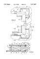
- FIG. 7is a perspective view illustrating a rib and a foam block used to control the flow of foam in the liquid state.
- FIG. 8schematically illustrates a door embodying the claimed invention in the process of being assembled.
- FIG. 9is an enlarged perspective view of part of Fig. 8.
- FIG. 10(a)is a partial side view illustrating a removable, temporary frame member.
- FIG. 10(b)is a cross-sectional view taken on line 10(b)--10(b) of FIG. 10(a).
- FIG. 11is an enlarged view of a portion of FIG. 4 showing the interlocking structure.
- FIG. 1illustrates the front of a door 10 embodying the present invention.
- the door 10is made up of a pair of opposed, congruent sheets 12 (a front sheet 14 and a rear sheet 16) spaced apart by a frame consisting of beams 18 located along the sheet edges 20.
- Each sheet 12has an outer side 22 and an inner side 24, and the inner sides 24 face each other.
- the sheets 12 and the framedefine a separation space 26 in the interior of the door 10.
- the separation space 26may be filled with a core, such as a foam core 28.
- wood support member 29may be employed in the separation space 26, especially adjacent the beams 18.
- the door 10 shown in the drawingshas a window opening 30 and is provided with a window frame 32 for retaining one or more window panes and/or a screen.
- a drain hole 33(FIGS. 3 and 6) may be provided in the bottom of the window frame 32.
- the inventionis not, however, limited to a door with a window, nor even to a door.
- each sheet 12are formed to have an inwardly projecting L-shaped zig-zag portion 34 which defines a ledge 36 at the free end of the "L” on the outer side 22 of the sheet 12, which is parallel with the main plane (or exposed face) of the sheet 12, and a ridge 38 adjacent to the connected end of the "L” on the inner side 24 of the sheet 12 and perpendicular to and extending inwardly from the main plain of the sheet 12.
- Each beam 18 which forms part of the framehas two longitudinal beam edges 40 which are formed to mate respectively with the zig-zag portion 34 of the two sheet edges 20.
- an L-shaped flange 42projects from the beam 18 and, spaced apart from the flange 42, an L-shaped hook 44 projects from the beam 18.
- the flange 42has its connected leg 43 in the main plane (i.e. the exposed face) of the beam 18, which is perpendicular to the main plane of the sheet 12, and has its free leg 45 extending inwardly from and approximately perpendicular to the connected leg 43 (i.e, approximately parallel to the main plane of the sheet 12).
- the hook 44includes a post 46 at its connected end which projects perpendicularly from the beam 18 and a cross member 48 at its free end which projects outwardly from and perpendicular to the post 46.
- the beam ends 50are mitered so that the beams 18 can fit together at right angles.
- the connecting structurescould be reversed. That is, the beam edges 40 could carry the zig-zag structure and the outer edges 20 of the sheets 12 could carry the flange/hook structure.
- FIGS. 8 and 9Assembly of the door 10 is illustrated in FIGS. 8 and 9.
- a beam 18is juxtaposed to a sheet end 20 so that the ridge 38 on the inner side 24 of the sheet 12 is opposite the space between the beam's flange 42 and hook post 46 and so that the flange 42 is adjacent the sheet ledge 36 and the hook 44 wraps around or embraces the sheet ledge 36.
- the beam 18is then slidably fed along most of the length of the sheet edge 20. This is done on all four sides of the door 10 until each mitered beam end 50 is immediately adjacent another mitered beam end 50. Assembly is completed by serially exerting force, such as by tapping, on one or more of the mitered beam ends 50. It has been found that this procedure will cause the beams 18 to snap into a rigid frame in which the adjacent mitered beam ends 50 are held together by compression forces exerted by the interacting beams themselves.
- fasteners of various typesmay be employed to fasten one or more of the beam end pairs to each other. Also, in certain applications, it may be desirable to fasten one or more of the beams 18 to a sheet 12 by adhesive or by fasteners of various types.
- this coreis in the form of foam which is introduced into the separation space in a liquid state and allowed or encouraged to harden.
- This foamcan be introduced after a panel has been assembled with a beam on each of its sides, as described above or done in other ways. The foam is then introduced through a port in one of the sheets or in the frame.
- the foam corewill provide enough structural strength so that a frame member is not needed on every side of the panel.
- permanent frame memberscan be provided at fewer than all of the sheet edges, using the beams and the method described above or other frame members and assembly methods.
- Temporary frame membersare then temporarily fastened to the unframed edges of the panel to complete a fully enclosed separation space.
- the liquid foamis then introduced. After it hardens, the temporary frame members are removed and may be used again. This reduces the weight and cost of the assembled panel.
- FIGS. 10(a) and 10(b)illustrate a type of temporary frame member 54.
- the sheet edges intended to receive a temporary frame member 54are provided with inwardly facing lips 56. These provide tracks to support the temporary frame member 54, which is an elongated plate with a finger hook 58 at one end.
- the temporary frame member 54has a port 59 for allowing the introduction of foam in the liquid state.
- the port 59is filled with a plug 61 until the foam has hardened.
- the temporary frame member 54is slid along the tracks of the edges of the two sheets 12 until it forms a completed door edge 60.
- the finger hook 58extends beyond the door edge 60. After the foam has been introduced and has hardened, the finger hook 58 facilitates removal of temporary frame member 54.
- the separation space 26has a width of 1.30 inches and each rib 62 has a height of 0.08 inches (except at the corners, as explained below), so that the height of flow area between the ribs 62 is 1.14 inches.
- the rib 62 described in the preceding paragraphis re-routed to accept an L-shaped, resilient foam block 64 which nestles between the re-routed portion 66 of the rib 62 and the window frame 32.
- the height of the re-routed portion 66 of the rib 62is increased so that foam block 64 will remain in place during assembly.
- the height of the rib 62is 0.25 inches.
- the height of the foam block 64is slightly greater than the thickness of the separation space 26 so that the foam block 64 is slightly compressed, thereby preventing the flow of foam over it. This keeps the liquid foam away from the critical corner areas of the window opening 30 during the filling process.
- the sheets 12may be compression molded sheet molding compound (SMC) panels or may be made of plastic of the thermoplastic or thermoset type and formed by injection molding, compression molding, blow molding or reaction injection molding or by vacuum forming or thermoforming. Other materials, including aluminum and steel, may be used as well. These may be roll-formed or extruded or formed by other techniques. Typically, when used in a storm door, the thickness of the sheets 12, if made of molded plastic, is in the range of 0.065 to 0.125 inches.
- the beams 18may be aluminum extrusions or may be made of other rigid materials by other processes.
- the foam for the foam coremay be a low density (e.g., 2 to 5 pounds per square foot), two-component, thermosetting, insulating polyurethane or an expanded polystyrene (EPS); other materials may be used as well.
- EPSexpanded polystyrene
Landscapes
- Engineering & Computer Science (AREA)
- Civil Engineering (AREA)
- Structural Engineering (AREA)
- Architecture (AREA)
- Securing Of Glass Panes Or The Like (AREA)
Abstract
Description
Claims (7)
Priority Applications (1)
| Application Number | Priority Date | Filing Date | Title |
|---|---|---|---|
| US08/392,574US5577363A (en) | 1995-02-23 | 1995-02-23 | Structural panel |
Applications Claiming Priority (1)
| Application Number | Priority Date | Filing Date | Title |
|---|---|---|---|
| US08/392,574US5577363A (en) | 1995-02-23 | 1995-02-23 | Structural panel |
Publications (1)
| Publication Number | Publication Date |
|---|---|
| US5577363Atrue US5577363A (en) | 1996-11-26 |
Family
ID=23551140
Family Applications (1)
| Application Number | Title | Priority Date | Filing Date |
|---|---|---|---|
| US08/392,574Expired - Fee RelatedUS5577363A (en) | 1995-02-23 | 1995-02-23 | Structural panel |
Country Status (1)
| Country | Link |
|---|---|
| US (1) | US5577363A (en) |
Cited By (26)
| Publication number | Priority date | Publication date | Assignee | Title |
|---|---|---|---|---|
| US5839240A (en)* | 1996-07-26 | 1998-11-24 | Steelcase Inc. | Partition construction and trim system therefor |
| US5870868A (en)* | 1996-06-25 | 1999-02-16 | Sinko Kogyo Co., Ltd. | Outer panel for air conditioner |
| US6138435A (en)* | 1995-08-25 | 2000-10-31 | Alusuisse Airex Ag | Profile sections for plate-like composite elements |
| US6389769B1 (en)* | 2000-07-05 | 2002-05-21 | Efp Corporation | Door and method of making same |
| US6619005B1 (en)* | 2002-04-16 | 2003-09-16 | Kuei Yung Wang Chen | Molded doors with large glass insert |
| US6688063B1 (en)* | 2000-07-25 | 2004-02-10 | Larson Manufacturing Company | Wood core exterior door with mortise lock |
| US6715245B2 (en) | 2002-04-03 | 2004-04-06 | Signature Door Co., Inc. | Impact resistant pane and mounting |
| US20040206021A1 (en)* | 2001-05-30 | 2004-10-21 | Aldino Albertelli | Production of glazed panels |
| US6962031B2 (en)* | 2001-01-11 | 2005-11-08 | Polymer Doors Limited | Doors |
| US20060010793A1 (en)* | 2004-07-15 | 2006-01-19 | Martino Ralph A | Indexing ribs for assembling a door, and door |
| US7007433B2 (en) | 2003-01-14 | 2006-03-07 | Centria | Features for thin composite architectural panels |
| US7007439B1 (en) | 2000-12-08 | 2006-03-07 | Larson Manufacturing Company Of South Dakota, Inc. | Door with lockset |
| US7117639B2 (en) | 2000-12-27 | 2006-10-10 | Larson Manufacturing Company Of South Dakota, Inc. | Reversible door having mortise hardware |
| US20060272247A1 (en)* | 2003-10-14 | 2006-12-07 | Bartlett Gary F | Door edge construction |
| US20060283143A1 (en)* | 2005-06-15 | 2006-12-21 | York International Corporation | Frameless viewport |
| US20110107703A1 (en)* | 2009-11-09 | 2011-05-12 | William Mullet | Door and method of manufacturing thereof |
| US20120040135A1 (en)* | 2008-12-04 | 2012-02-16 | Jon Micheal Werthen | Sandwich Panel, Support Member for Use in a Sandwich Panel and Aircraft Provided with Such a Sandwich Panel |
| US8136327B1 (en)* | 2010-06-18 | 2012-03-20 | Plyco Corp. | Door adapted for automated assembly |
| US20130192155A1 (en)* | 2012-01-30 | 2013-08-01 | Yvan Bergeron | Load bearing wall system |
| US9624666B2 (en) | 2012-05-18 | 2017-04-18 | Nexgen Framing Solutions LLC | Structural insulated panel framing system |
| US20170130514A1 (en)* | 2015-11-06 | 2017-05-11 | Usa Worldwide Door Components (Pinghu) Co. Ltd. | Middle strip of a door frame |
| US20180030776A1 (en)* | 2016-07-29 | 2018-02-01 | Masonite Corporation | Door assemblies with insulated glazing unit venting |
| US10415266B2 (en)* | 2015-02-10 | 2019-09-17 | Special-Lite, Inc. | Door with adjustable lock plate connectors |
| US11105143B2 (en)* | 2018-04-25 | 2021-08-31 | Endura Products, Llc | Door assembly |
| WO2021188645A1 (en)* | 2020-03-19 | 2021-09-23 | V Tech Industries, L.P. | Hurricane door |
| US11230845B2 (en)* | 2018-02-07 | 2022-01-25 | Kwang Steel Co., Ltd. | Building exterior panel and assembly structure thereof |
Citations (23)
| Publication number | Priority date | Publication date | Assignee | Title |
|---|---|---|---|---|
| US2042721A (en)* | 1935-05-09 | 1936-06-02 | Loewy Morris | Metal panel construction |
| GB512433A (en)* | 1938-03-02 | 1939-09-15 | Metal Trim Ltd | Improvements in or relating to metal doors, windows and the like |
| US2376653A (en)* | 1942-03-31 | 1945-05-22 | Gen Electric | Laminated structure |
| US3235040A (en)* | 1963-05-03 | 1966-02-15 | Dow Chemical Co | Sandwich panel structure with edge trim |
| US3334464A (en)* | 1965-10-21 | 1967-08-08 | Anaconda Aluminum Co | Door and method for making same |
| US3359699A (en)* | 1965-05-26 | 1967-12-26 | Pittsburgh Plate Glass Co | Edge lock for metal panels |
| US3885351A (en)* | 1973-11-19 | 1975-05-27 | Johnson Sheet Metal Works Co | Metal door assembly |
| US3987588A (en)* | 1973-11-19 | 1976-10-26 | Johnson Sheet Metal Works Corporation | Metal door assembly and method of production |
| US4161567A (en)* | 1977-09-12 | 1979-07-17 | Proctor & Schwartz, Inc. | Panels for industrial dryers and other heated enclosures having stainless steel end structural sheet elements |
| US4281493A (en)* | 1975-10-16 | 1981-08-04 | Pitt William V | Atmospheric resistant doors |
| US4374693A (en)* | 1977-04-27 | 1983-02-22 | Pitt William V | Method of manufacturing atmospheric resistant doors |
| US4409768A (en)* | 1980-06-02 | 1983-10-18 | Joseph Boden | Prefabricated wall panel |
| US4546585A (en)* | 1983-08-02 | 1985-10-15 | Peachtree Doors, Inc. | Door panel and method of making |
| US4550540A (en)* | 1983-01-07 | 1985-11-05 | Therma-Tru Corp. | Compression molded door assembly |
| US4580380A (en)* | 1983-11-07 | 1986-04-08 | Ballard Derryl R | Composite filled interior structural box beams |
| US4748781A (en)* | 1986-10-22 | 1988-06-07 | Foamseal, Inc. | Method of bonding structural support channels to a panel and structural building module formed |
| US4864789A (en)* | 1988-06-02 | 1989-09-12 | Therma-Tru Corp. | Compression molded door assembly |
| US4922674A (en)* | 1988-06-15 | 1990-05-08 | Therma-Tru Corp. | Compression molded door assembly |
| US4941304A (en)* | 1987-08-14 | 1990-07-17 | Lewellin Richard L | Insulation body |
| US5077948A (en)* | 1989-09-01 | 1992-01-07 | Larson Manufacturing Company | Polymer enclosed door |
| US5142835A (en)* | 1990-10-12 | 1992-09-01 | Taylor Building Products Company | Reaction injection molded door assembly |
| US5161346A (en)* | 1989-09-01 | 1992-11-10 | Larson Manufacturing Company | Polymer enclosed door |
| CA2065955A1 (en)* | 1992-04-14 | 1993-10-15 | Jacques Menard | Composite exterior door structure |
- 1995
- 1995-02-23USUS08/392,574patent/US5577363A/ennot_activeExpired - Fee Related
Patent Citations (23)
| Publication number | Priority date | Publication date | Assignee | Title |
|---|---|---|---|---|
| US2042721A (en)* | 1935-05-09 | 1936-06-02 | Loewy Morris | Metal panel construction |
| GB512433A (en)* | 1938-03-02 | 1939-09-15 | Metal Trim Ltd | Improvements in or relating to metal doors, windows and the like |
| US2376653A (en)* | 1942-03-31 | 1945-05-22 | Gen Electric | Laminated structure |
| US3235040A (en)* | 1963-05-03 | 1966-02-15 | Dow Chemical Co | Sandwich panel structure with edge trim |
| US3359699A (en)* | 1965-05-26 | 1967-12-26 | Pittsburgh Plate Glass Co | Edge lock for metal panels |
| US3334464A (en)* | 1965-10-21 | 1967-08-08 | Anaconda Aluminum Co | Door and method for making same |
| US3885351A (en)* | 1973-11-19 | 1975-05-27 | Johnson Sheet Metal Works Co | Metal door assembly |
| US3987588A (en)* | 1973-11-19 | 1976-10-26 | Johnson Sheet Metal Works Corporation | Metal door assembly and method of production |
| US4281493A (en)* | 1975-10-16 | 1981-08-04 | Pitt William V | Atmospheric resistant doors |
| US4374693A (en)* | 1977-04-27 | 1983-02-22 | Pitt William V | Method of manufacturing atmospheric resistant doors |
| US4161567A (en)* | 1977-09-12 | 1979-07-17 | Proctor & Schwartz, Inc. | Panels for industrial dryers and other heated enclosures having stainless steel end structural sheet elements |
| US4409768A (en)* | 1980-06-02 | 1983-10-18 | Joseph Boden | Prefabricated wall panel |
| US4550540A (en)* | 1983-01-07 | 1985-11-05 | Therma-Tru Corp. | Compression molded door assembly |
| US4546585A (en)* | 1983-08-02 | 1985-10-15 | Peachtree Doors, Inc. | Door panel and method of making |
| US4580380A (en)* | 1983-11-07 | 1986-04-08 | Ballard Derryl R | Composite filled interior structural box beams |
| US4748781A (en)* | 1986-10-22 | 1988-06-07 | Foamseal, Inc. | Method of bonding structural support channels to a panel and structural building module formed |
| US4941304A (en)* | 1987-08-14 | 1990-07-17 | Lewellin Richard L | Insulation body |
| US4864789A (en)* | 1988-06-02 | 1989-09-12 | Therma-Tru Corp. | Compression molded door assembly |
| US4922674A (en)* | 1988-06-15 | 1990-05-08 | Therma-Tru Corp. | Compression molded door assembly |
| US5077948A (en)* | 1989-09-01 | 1992-01-07 | Larson Manufacturing Company | Polymer enclosed door |
| US5161346A (en)* | 1989-09-01 | 1992-11-10 | Larson Manufacturing Company | Polymer enclosed door |
| US5142835A (en)* | 1990-10-12 | 1992-09-01 | Taylor Building Products Company | Reaction injection molded door assembly |
| CA2065955A1 (en)* | 1992-04-14 | 1993-10-15 | Jacques Menard | Composite exterior door structure |
Cited By (41)
| Publication number | Priority date | Publication date | Assignee | Title |
|---|---|---|---|---|
| US6138435A (en)* | 1995-08-25 | 2000-10-31 | Alusuisse Airex Ag | Profile sections for plate-like composite elements |
| US5870868A (en)* | 1996-06-25 | 1999-02-16 | Sinko Kogyo Co., Ltd. | Outer panel for air conditioner |
| US5839240A (en)* | 1996-07-26 | 1998-11-24 | Steelcase Inc. | Partition construction and trim system therefor |
| US6389769B1 (en)* | 2000-07-05 | 2002-05-21 | Efp Corporation | Door and method of making same |
| US6688063B1 (en)* | 2000-07-25 | 2004-02-10 | Larson Manufacturing Company | Wood core exterior door with mortise lock |
| US7007439B1 (en) | 2000-12-08 | 2006-03-07 | Larson Manufacturing Company Of South Dakota, Inc. | Door with lockset |
| US7117639B2 (en) | 2000-12-27 | 2006-10-10 | Larson Manufacturing Company Of South Dakota, Inc. | Reversible door having mortise hardware |
| US6962031B2 (en)* | 2001-01-11 | 2005-11-08 | Polymer Doors Limited | Doors |
| US20040206021A1 (en)* | 2001-05-30 | 2004-10-21 | Aldino Albertelli | Production of glazed panels |
| US7543416B2 (en)* | 2001-05-30 | 2009-06-09 | Acell Holdings Limited | Production of glazed panels |
| US6715245B2 (en) | 2002-04-03 | 2004-04-06 | Signature Door Co., Inc. | Impact resistant pane and mounting |
| US6619005B1 (en)* | 2002-04-16 | 2003-09-16 | Kuei Yung Wang Chen | Molded doors with large glass insert |
| US7007433B2 (en) | 2003-01-14 | 2006-03-07 | Centria | Features for thin composite architectural panels |
| US20070039275A1 (en)* | 2003-01-14 | 2007-02-22 | Keith Boyer | Features for thin composite architectural panels |
| US20110120044A1 (en)* | 2003-10-14 | 2011-05-26 | Bartlett Garry F | Door Edge Construction |
| US20060272247A1 (en)* | 2003-10-14 | 2006-12-07 | Bartlett Gary F | Door edge construction |
| US7886501B2 (en)* | 2003-10-14 | 2011-02-15 | Construction Specialties, Inc. | Door edge construction |
| US20060010793A1 (en)* | 2004-07-15 | 2006-01-19 | Martino Ralph A | Indexing ribs for assembling a door, and door |
| US20060283143A1 (en)* | 2005-06-15 | 2006-12-21 | York International Corporation | Frameless viewport |
| US20120040135A1 (en)* | 2008-12-04 | 2012-02-16 | Jon Micheal Werthen | Sandwich Panel, Support Member for Use in a Sandwich Panel and Aircraft Provided with Such a Sandwich Panel |
| US20110107703A1 (en)* | 2009-11-09 | 2011-05-12 | William Mullet | Door and method of manufacturing thereof |
| US8136327B1 (en)* | 2010-06-18 | 2012-03-20 | Plyco Corp. | Door adapted for automated assembly |
| US20130192155A1 (en)* | 2012-01-30 | 2013-08-01 | Yvan Bergeron | Load bearing wall system |
| US8640410B2 (en)* | 2012-01-30 | 2014-02-04 | Yvan Bergeron | Load bearing wall system |
| US10760270B2 (en) | 2012-05-18 | 2020-09-01 | Nexgen Framing Solutions LLC | Structural insulated panel framing system |
| US9624666B2 (en) | 2012-05-18 | 2017-04-18 | Nexgen Framing Solutions LLC | Structural insulated panel framing system |
| US10415266B2 (en)* | 2015-02-10 | 2019-09-17 | Special-Lite, Inc. | Door with adjustable lock plate connectors |
| US20170130514A1 (en)* | 2015-11-06 | 2017-05-11 | Usa Worldwide Door Components (Pinghu) Co. Ltd. | Middle strip of a door frame |
| US9976334B2 (en)* | 2015-11-06 | 2018-05-22 | Usa Worldwide Door Components (Pinghu) Co., Ltd. | Middle strip of a door frame |
| US11293212B2 (en) | 2016-07-29 | 2022-04-05 | Masonite Corporation | Door assemblies with insulated glazing unit venting |
| US11225827B2 (en) | 2016-07-29 | 2022-01-18 | Masonite Corporation | Door assemblies with insulated glazing unit venting |
| US20180030776A1 (en)* | 2016-07-29 | 2018-02-01 | Masonite Corporation | Door assemblies with insulated glazing unit venting |
| US11739586B2 (en) | 2016-07-29 | 2023-08-29 | Masonite Corporation | Door assemblies with insulated glazing unit venting |
| US11781372B2 (en) | 2016-07-29 | 2023-10-10 | Masonite Corporation | Door assemblies with insulated glazing unit venting |
| US11230845B2 (en)* | 2018-02-07 | 2022-01-25 | Kwang Steel Co., Ltd. | Building exterior panel and assembly structure thereof |
| US11105143B2 (en)* | 2018-04-25 | 2021-08-31 | Endura Products, Llc | Door assembly |
| US11111715B2 (en)* | 2018-04-25 | 2021-09-07 | Endura Products, Llc | Door assembly |
| US11629545B2 (en) | 2018-04-25 | 2023-04-18 | Endura Products, Llc | Door assembly |
| US11993976B2 (en) | 2018-04-25 | 2024-05-28 | Endura Products, Llc | Door assembly |
| US12428901B2 (en) | 2018-04-25 | 2025-09-30 | Endura Products, Llc | Door assembly |
| WO2021188645A1 (en)* | 2020-03-19 | 2021-09-23 | V Tech Industries, L.P. | Hurricane door |
Similar Documents
| Publication | Publication Date | Title |
|---|---|---|
| US5577363A (en) | Structural panel | |
| US3826054A (en) | Building insulation and sheathing | |
| US4555885A (en) | Filler strip with locking clip | |
| US6988344B1 (en) | Modular wall structural elements, and methods of using same | |
| CA2286260C (en) | Metal door with continuous frame and method | |
| US4805357A (en) | Structural mold system | |
| US4441290A (en) | Glazing fastener for mounting either rigid or flexible storm windows | |
| US5709056A (en) | Cladding units for building and seal structure for joint thereof | |
| DE19629503C2 (en) | Cladding units for a building and sealing structure for their joints | |
| US4656785A (en) | Weatherseal | |
| US3998015A (en) | Resilient-edged wallboard and wall assembled therewith | |
| US4637299A (en) | Vent opening for portable building wall | |
| JP3225343B2 (en) | Panel mounting structure of panel mounting frame | |
| US4580373A (en) | Building element and roof structure comprising a plurality of such elements | |
| US4665676A (en) | Frame | |
| US2901810A (en) | Pouring form for windows | |
| WO2002090683A3 (en) | Improvements in a stackable construction panel system | |
| EP0240161A2 (en) | Sandwich panel | |
| CA1062550A (en) | Window or door frame | |
| US3075621A (en) | Wall panel and process of assembling same | |
| US5005333A (en) | Panel-framing assembly and assembly method therefor | |
| US3417529A (en) | Drive cleat connector | |
| JPH0421857Y2 (en) | ||
| EP0382278B1 (en) | Panel for wall construction | |
| US4813195A (en) | Solid cavity corner for lockstrip gaskets |
Legal Events
| Date | Code | Title | Description |
|---|---|---|---|
| AS | Assignment | Owner name:MENASHA CORPORATION, WISCONSIN Free format text:ASSIGNMENT OF ASSIGNORS INTEREST;ASSIGNOR:TATE, JAMES R.;REEL/FRAME:007646/0070 Effective date:19950606 | |
| AS | Assignment | Owner name:MENASHA CORPORATION, WISCONSIN Free format text:ASSIGNMENT OF ASSIGNORS INTEREST;ASSIGNORS:LEE, ALLEN E.;OLSON, VERN D.;ZACHER, BRYAN P.;REEL/FRAME:007745/0110 Effective date:19951016 | |
| AS | Assignment | Owner name:APPLIED MOLDED PRODUCTS, CORP, WISCONSIN Free format text:ASSIGNMENT OF ASSIGNORS INTEREST;ASSIGNOR:MENASHA CORPORATION;REEL/FRAME:008559/0877 Effective date:19970609 Owner name:AMERICAN NATIONAL BANK & TRUST COMPANY OF CHICAGO, Free format text:ASSIGNMENT OF ASSIGNORS INTEREST;ASSIGNOR:APPLIED MOLDED PRODUCTS, CORP.;REEL/FRAME:008559/0879 Effective date:19970609 | |
| AS | Assignment | Owner name:MENASHA MATERIAL HANDLING CORPORATION, WISCONSIN Free format text:ASSIGNMENT OF ASSIGNORS INTEREST;ASSIGNOR:MENASHA CORPORATION;REEL/FRAME:010639/0536 Effective date:19991231 | |
| FPAY | Fee payment | Year of fee payment:4 | |
| SULP | Surcharge for late payment | ||
| REMI | Maintenance fee reminder mailed | ||
| LAPS | Lapse for failure to pay maintenance fees | ||
| LAPS | Lapse for failure to pay maintenance fees | Free format text:PATENT EXPIRED FOR FAILURE TO PAY MAINTENANCE FEES (ORIGINAL EVENT CODE: EXP.); ENTITY STATUS OF PATENT OWNER: LARGE ENTITY | |
| STCH | Information on status: patent discontinuation | Free format text:PATENT EXPIRED DUE TO NONPAYMENT OF MAINTENANCE FEES UNDER 37 CFR 1.362 | |
| FP | Lapsed due to failure to pay maintenance fee | Effective date:20041126 |