US5575759A - Methods of using inflatable retraction devices in laparoscopic surgery - Google Patents
Methods of using inflatable retraction devices in laparoscopic surgeryDownload PDFInfo
- Publication number
- US5575759A US5575759AUS08/457,396US45739695AUS5575759AUS 5575759 AUS5575759 AUS 5575759AUS 45739695 AUS45739695 AUS 45739695AUS 5575759 AUS5575759 AUS 5575759A
- Authority
- US
- United States
- Prior art keywords
- retraction device
- chamber
- window
- inflatable retraction
- main chamber
- Prior art date
- Legal status (The legal status is an assumption and is not a legal conclusion. Google has not performed a legal analysis and makes no representation as to the accuracy of the status listed.)
- Expired - Lifetime
Links
Images


Classifications
- A—HUMAN NECESSITIES
- A61—MEDICAL OR VETERINARY SCIENCE; HYGIENE
- A61B—DIAGNOSIS; SURGERY; IDENTIFICATION
- A61B17/00—Surgical instruments, devices or methods
- A61B17/34—Trocars; Puncturing needles
- A61B17/3417—Details of tips or shafts, e.g. grooves, expandable, bendable; Multiple coaxial sliding cannulas, e.g. for dilating
- A—HUMAN NECESSITIES
- A61—MEDICAL OR VETERINARY SCIENCE; HYGIENE
- A61B—DIAGNOSIS; SURGERY; IDENTIFICATION
- A61B17/00—Surgical instruments, devices or methods
- A61B17/02—Surgical instruments, devices or methods for holding wounds open, e.g. retractors; Tractors
- A61B17/0218—Surgical instruments, devices or methods for holding wounds open, e.g. retractors; Tractors for minimally invasive surgery
- A—HUMAN NECESSITIES
- A61—MEDICAL OR VETERINARY SCIENCE; HYGIENE
- A61B—DIAGNOSIS; SURGERY; IDENTIFICATION
- A61B17/00—Surgical instruments, devices or methods
- A61B17/02—Surgical instruments, devices or methods for holding wounds open, e.g. retractors; Tractors
- A61B17/0281—Abdominal wall lifters
- A—HUMAN NECESSITIES
- A61—MEDICAL OR VETERINARY SCIENCE; HYGIENE
- A61B—DIAGNOSIS; SURGERY; IDENTIFICATION
- A61B17/00—Surgical instruments, devices or methods
- A61B17/22—Implements for squeezing-off ulcers or the like on inner organs of the body; Implements for scraping-out cavities of body organs, e.g. bones; for invasive removal or destruction of calculus using mechanical vibrations; for removing obstructions in blood vessels, not otherwise provided for
- A61B17/22031—Gripping instruments, e.g. forceps, for removing or smashing calculi
- A61B17/22032—Gripping instruments, e.g. forceps, for removing or smashing calculi having inflatable gripping elements
- A—HUMAN NECESSITIES
- A61—MEDICAL OR VETERINARY SCIENCE; HYGIENE
- A61B—DIAGNOSIS; SURGERY; IDENTIFICATION
- A61B90/00—Instruments, implements or accessories specially adapted for surgery or diagnosis and not covered by any of the groups A61B1/00 - A61B50/00, e.g. for luxation treatment or for protecting wound edges
- A61B90/50—Supports for surgical instruments, e.g. articulated arms
- A—HUMAN NECESSITIES
- A61—MEDICAL OR VETERINARY SCIENCE; HYGIENE
- A61B—DIAGNOSIS; SURGERY; IDENTIFICATION
- A61B17/00—Surgical instruments, devices or methods
- A61B17/34—Trocars; Puncturing needles
- A61B17/3462—Trocars; Puncturing needles with means for changing the diameter or the orientation of the entrance port of the cannula, e.g. for use with different-sized instruments, reduction ports, adapter seals
- A—HUMAN NECESSITIES
- A61—MEDICAL OR VETERINARY SCIENCE; HYGIENE
- A61B—DIAGNOSIS; SURGERY; IDENTIFICATION
- A61B17/00—Surgical instruments, devices or methods
- A61B17/00234—Surgical instruments, devices or methods for minimally invasive surgery
- A61B2017/00238—Type of minimally invasive operation
- A61B2017/00261—Discectomy
- A—HUMAN NECESSITIES
- A61—MEDICAL OR VETERINARY SCIENCE; HYGIENE
- A61B—DIAGNOSIS; SURGERY; IDENTIFICATION
- A61B17/00—Surgical instruments, devices or methods
- A61B2017/00535—Surgical instruments, devices or methods pneumatically or hydraulically operated
- A—HUMAN NECESSITIES
- A61—MEDICAL OR VETERINARY SCIENCE; HYGIENE
- A61B—DIAGNOSIS; SURGERY; IDENTIFICATION
- A61B17/00—Surgical instruments, devices or methods
- A61B2017/00535—Surgical instruments, devices or methods pneumatically or hydraulically operated
- A61B2017/00557—Surgical instruments, devices or methods pneumatically or hydraulically operated inflatable
- A—HUMAN NECESSITIES
- A61—MEDICAL OR VETERINARY SCIENCE; HYGIENE
- A61B—DIAGNOSIS; SURGERY; IDENTIFICATION
- A61B17/00—Surgical instruments, devices or methods
- A61B17/30—Surgical pincettes, i.e. surgical tweezers without pivotal connections
- A61B2017/306—Surgical pincettes, i.e. surgical tweezers without pivotal connections holding by means of suction
- A—HUMAN NECESSITIES
- A61—MEDICAL OR VETERINARY SCIENCE; HYGIENE
- A61B—DIAGNOSIS; SURGERY; IDENTIFICATION
- A61B17/00—Surgical instruments, devices or methods
- A61B17/32—Surgical cutting instruments
- A61B2017/320044—Blunt dissectors
- A61B2017/320048—Balloon dissectors
- A—HUMAN NECESSITIES
- A61—MEDICAL OR VETERINARY SCIENCE; HYGIENE
- A61B—DIAGNOSIS; SURGERY; IDENTIFICATION
- A61B17/00—Surgical instruments, devices or methods
- A61B17/34—Trocars; Puncturing needles
- A61B2017/348—Means for supporting the trocar against the body or retaining the trocar inside the body
- A61B2017/3482—Means for supporting the trocar against the body or retaining the trocar inside the body inside
- A61B2017/3484—Anchoring means, e.g. spreading-out umbrella-like structure
- A61B2017/3486—Balloon
- A—HUMAN NECESSITIES
- A61—MEDICAL OR VETERINARY SCIENCE; HYGIENE
- A61B—DIAGNOSIS; SURGERY; IDENTIFICATION
- A61B90/00—Instruments, implements or accessories specially adapted for surgery or diagnosis and not covered by any of the groups A61B1/00 - A61B50/00, e.g. for luxation treatment or for protecting wound edges
- A61B90/30—Devices for illuminating a surgical field, the devices having an interrelation with other surgical devices or with a surgical procedure
- A61B2090/306—Devices for illuminating a surgical field, the devices having an interrelation with other surgical devices or with a surgical procedure using optical fibres
- Y—GENERAL TAGGING OF NEW TECHNOLOGICAL DEVELOPMENTS; GENERAL TAGGING OF CROSS-SECTIONAL TECHNOLOGIES SPANNING OVER SEVERAL SECTIONS OF THE IPC; TECHNICAL SUBJECTS COVERED BY FORMER USPC CROSS-REFERENCE ART COLLECTIONS [XRACs] AND DIGESTS
- Y10—TECHNICAL SUBJECTS COVERED BY FORMER USPC
- Y10T—TECHNICAL SUBJECTS COVERED BY FORMER US CLASSIFICATION
- Y10T156/00—Adhesive bonding and miscellaneous chemical manufacture
- Y10T156/10—Methods of surface bonding and/or assembly therefor
- Y10T156/1002—Methods of surface bonding and/or assembly therefor with permanent bending or reshaping or surface deformation of self sustaining lamina
- Y10T156/1003—Methods of surface bonding and/or assembly therefor with permanent bending or reshaping or surface deformation of self sustaining lamina by separating laminae between spaced secured areas [e.g., honeycomb expanding]
Definitions
- This applicationrelates to inflatable dissectional retraction devices for use in laparoscopic surgery, and surgical procedures using inflatable dissectional retraction devices.
- Laparoscopydates back to the mm of the 20th Century. Early laparoscopic techniques were used primarily for diagnostic purposes to view the internal organs without the necessity of conventional surgery. Since the 1930s, laparoscopy has been used for sterilization and, more recently, for suturing of hemas. U.S. Pat. Nos. 4,919,152 and 4,944,443 are concerned with techniques for suturing hemas. Another recent innovation is the use of laparoscopic surgery for removing the gallbladder.
- the modified Foley cathetercomprises a small, substantially spherical balloon on the end of a catheter which is inserted through a small incision into the body. After insertion, the balloon is inflated.
- the modified Foley catheteris used in a similar manner to a conventional retractor, but the retracted organ or tissue is contacted by the relatively large surface area of the balloon.
- Such a retractorreduces damage to retracted organs or tissues, but is inconvenient to use because it has to be kept in place by means of an external clamping arrangement, and its relatively large inflated balloon tends to obstruct access to the site to be treated.
- U.S. patent application Ser. No. 07/794,590discloses a number of different inflatable retraction devices for retracting an organ or a tissue (an "organ”) to provide access to an organ or a tissue (a "tissue").
- the inflatable retraction devices disclosed in the parent applicationare multi-chambered.
- An inflatable retraction deviceis packaged in a collapsed and compacted state, and is laparoscopically placed adjacent to the organ to be retracted.
- the large, main chamber of the inflatable retraction deviceis then inflated to expand the main chamber, which retracts the organ. Expanding the inflatable retraction device not only retracts the organ, but also causes the expanded main chamber to obstruct access to the tissue.
- a second inflatable chamberis inflated.
- the second chamberalthough normally providing less of a retraction force than the main chamber, provides sufficient retraction force to maintain the organ in its retracted state after the inflation pressure in the main chamber is released. Then, apertures are cut in the envelope of the main chamber to provide access to the tissue to be treated. The tissue is treated using instruments passed through the main chamber.
- a herniais the protrusion of part of a body part or structure through a defect in the wall of a surrounding structure. Most commonly, a hernia is the protrusion of part of abdominal contents, including bowel, through a tear or weakness in the abdominal wall, or through the inguinal canal into the scrotum.
- An abdominal herniais normally repaired by suturing or stapling a mesh patch over the site of the tear or weakness.
- the anatomical weakness of the herniacan be approached from inside or outside the abdomen. If approached intra-abdominally, the mesh patch, which has a rough surface, can irritate the bowel and cause adhesions. It is therefore preferred to install the patch properitoneally, in which the mesh patch is attached to the properitoneal fascia of the abdominal wall, and covered by the peritoneum. To attach the mesh patch to the properitoneal fascia, the peritoneum must be dissected from the properitoneal fascia.
- an incisionis made in the abdominal wall close to the site of the hernia.
- the incisionis made through the abdominal wall as far as the properitoneal fat layer.
- the peritoneumis then blunt dissected from the properitoneal fat layer by passing a finger or a rigid probe through the incision and sweeping the finger or rigid probe under the pefitoneum.
- the space between the peritoneum and the properitoneal fat layeris insufflated to provide a working space in which to apply the mesh patch to the properitoneal fascia.
- the laparoscopic hernia repair technique described in the parent applicationenables a mesh patch to be attached to the properitoneal fascia without breaching the peritoneum.
- An incisionis made through the abdominal wall as far as the properitoneal fat layer.
- An inflatable retraction device of the type described aboveis pushed through the incision into contact with the peritoneum, and is used to nudge the peritoneum from the underlying layers.
- the main chamber of the inflatable retraction deviceis then inflated to expand the inflatable retraction device towards the site of the hernia. As it expands, the inflatable retraction device gently dissects the peritoneum from the underlying layers.
- the second chamberis inflated.
- the second chamberenables the inflatable retraction device to continue to maintain separation of the peritoneum from the overlying layers after the inflation pressure in the main chamber has been released.
- One or more aperturesare then cut in the envelope of the main chamber to provide access to the site of the hernia for instruments passed into the main chamber.
- instrumentspass to the site of the hernia through the main chamber situated between the peritoneum and the overlying layers.
- a mesh patchcan be attached to the properitoneal fascia without breaching the peritoneum.
- U.S. patent application Ser. No. 07/911,714which is also a Continuation-in-Part of the parent application, and which is also incorporated herein by reference, discloses a properitoneal hernia repair technique which differs from the technique using the above-described two-chambered inflatable retraction device.
- the technique described in the '714 applicationuses a single-chambered inflatable retraction device to create a working space at the site of the hernia. The inflatable retraction device is removed and the working space is insufflated prior to treating the hernia.
- a small incisionis made at the umbilicus through the abdominal wall as far as the peritoneum.
- the single-chambered inflatable retraction deviceis introduced through the incision and is used to nudge the peritoneum away from the adjacent fat layer.
- the chamberis then partially inflated to expand the chamber, which dissects more of the peritoneum away from the adjacent fat layer.
- the chamberis then deflated and advanced towards the site of the hernia. The inflating and advancing process can be repeated to form a tunnel between the incision and the site of the hernia.
- the chamberWhen the site of the hernia is reached, the chamber is fully expanded to create a working space at the site of the hernia.
- An endoscopecan be inserted into the expanded chamber to obtain a visual conformation of the hernia defect.
- the inflatable retraction deviceis then withdrawn from the working space, and a trocar tube anchored by a small balloon is inserted into the incision.
- Insufflation gasis passed through the trocar tube to insufflate the tunnel and the working space.
- the herniais then treated using instruments passed into the insufflated working space through the insufflated tunnel.
- the peritoneumcan sometimes rise up and obstruct access to the site of the hernia. This occurs if the pefitoneum is breached during the dissection process, and insufflation gas leaks into the abdominal cavity. This equalizes the pressure across the peritoneum, and the insufflation pressure no longer depresses the peritoneum away from the site of the hernia. It has also been found that blood accumulates in the tunnel leading to the site of the hernia, and contaminates the lens of the endoscope when the endoscope is passed through the tunnel. The endoscope must then be withdrawn from the tunnel, its lens cleaned, and another attempt to insert the endoscope made.
- the inventionprovides an apparatus for retracting an organ to gain access to treat a tissue.
- the apparatuscomprises a main envelope, a second envelope, a first inflation device and a second inflation device.
- the main envelopeencloses a main chamber, and includes a window and a removable window.
- the second envelopecovers substantially all the main envelope, except the window and the removable window.
- the second envelope and the main envelopeenclose a second chamber outside the main chamber.
- the first inflation devicepasses a fluid into the main chamber to expand the main chamber and the second chamber from a compacted state to retract the organ.
- the second inflation devicepasses a fluid into the second chamber to further expand the second chamber to maintain the organ in its retracted state after fluid has been released from the main chamber.
- the inventionalso provides a pressure control valve that allows fluid to pass in a first direction, and allows fluid to pass in a second direction, opposite to the first direction, only when fluid has a pressure in the second direction exceeding a predetermined limit.
- the valvecomprises a valve body including a valve seat.
- the valvealso comprises a one-way valve seating on the valve seat in the valve body.
- the one-way valveis oriented to allow fluid to pass in the first direction, and to prevent fluid from passing in the second direction.
- the valvecomprises a compression spring disposed between the one-way valve and the valve body to apply a seating force between the one-way valve and the valve seat.
- the inventionalso provides a method for properitoneal hernia repair.
- an inflatable retraction deviceis provided in a compacted state.
- the inflatable retraction deviceincludes a main envelope enclosing a main chamber and including a window and a removable window; and a second envelope covering substantially all the main envelope, except the window and the removable window.
- the second envelope and the main envelopeenclose a second chamber outside the main chamber.
- the devicealso includes an attachment point centered in the removable window, and an insertion shaft passing through the main chamber, and having a distal end temporarily attached to the attachment point.
- the attachment pointprovides a distal tip for inflatable retraction device.
- an incisionis made through the abdominal wall at the umbilicus as far as the properitoneal layer, and the distal tip of the inflatable retraction device is inserted into the incision.
- the inflatable retraction deviceis then used to dissect the peritoneum from the properitoneal layer while advancing the inflatable retraction device inferiority between the peritoneum and the properitoneal layer towards the hernia.
- a fluidis passed into the main chamber to expand the main chamber and the second chamber from the compacted state and to dissect further the peritoneum from the properitoneal layer.
- a fluidis passed into the second chamber to further expand the second chamber. Fluid is then released from the main chamber, and the removable window is detached from the main envelope.
- an inflatable retraction devicein a compacted state.
- the inflatable retraction deviceincludes a main envelope enclosing a main chamber, and including a window and a removable window.
- the devicealso includes a second envelope covering substantially all the main envelope, except the window and the removable window.
- the second envelope and the main envelopeenclose a second chamber outside the main chamber.
- the inflatable retraction deviceis placed in the compacted state adjacent the organ. A fluid is passed into the main chamber to expand the main chamber and the second chamber from the compacted state to retract the organ. A fluid is passed into the second chamber to further expand the second chamber. Fluid is released from the main chamber. And the removable window is detached from the main envelope.
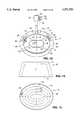
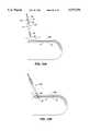
- FIGS. 1A, 1B, 1C, 1D, and 1Eshow a top view, a front elevation, a bottom view, a side elevation, and a cross-sectional view of the preferred embodiment of the inflatable retraction device according to the invention.
- FIG. 1Fshows a cross sectional view of the preferred embodiment of the inflatable retraction device with the insertion shaft in place.
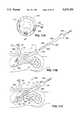
- FIG. 2shows the preferred embodiment of inflatable retraction device as it fits in the space bounded by the pelvis in the male abdomen in the course of repairing an inguinal hernia.
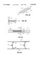
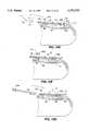
- FIG. 3Ashows baffle halves prior to welding.
- FIG. 3Bshows welding the baffle halves together.
- FIG. 3Cshows the complete baffle being welded to the main envelope and the second envelope.
- FIG. 3Dshows the baffles extending between the main envelope and the second envelope in the expanded second chamber.
- FIG. 4Ashows the preferred form of the junction between the top-wall part and the side wall part of the second chamber.
- the junctionincludes the interconnection chamber.
- FIG. 4Bis a view of the interconnection chamber at the junction of the side wall and the top wall looking outwards from inside the main chamber.
- FIG. 4Cis an exploded view of the preferred form of the junction between the top-wall part and the side wall part of the second chamber.
- FIG. 5is a cross sectional view of a small piece of the envelope material according to the invention.
- FIG. 6Ais a view of the removable window from inside the main chamber.
- FIG. 6Bis a plan view of the removable window showing the attachment frame.
- FIG. 6Cshows the removable window in place adjacent the main envelope prior to welding.
- FIG. 6Dshows the removable window after welding the attachment frame to the main envelope.
- FIG. 6Eshows the removable window partially peeled away from the main envelope.
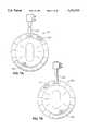
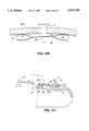
- FIG. 7Ais a plan view of an inflatable retraction device according to the invention with windows located for repairing hernias located on the right side of the body.
- FIG. 7Bis a plan view of an inflatable retraction device according to the invention with windows located for repairing hernias located on the left side of the body.
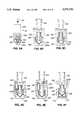
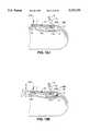
- FIG. 8Ashows the preferred embodiment of a pressure control valve according to the invention with a fixed release pressure.
- FIG. 8Bshows a fast alternative embodiment of a pressure control valve according to the invention with a fixed release pressure.
- FIG. 8Cshows a second alternative embodiment of a pressure control valve according to the invention with a fixed release pressure.
- FIG. 8Dshows a fast embodiment of a pressure control valve according to the invention with a variable release pressure.
- FIG. 8Eshows a second embodiment of a pressure control valve according to the invention with a variable release pressure.
- FIG. 8Fshows a third embodiment of a pressure control valve according to the invention with a variable release pressure.
- FIG. 9Ais a side view of the inflatable retraction device according to the invention packaged for insertion into the body.
- FIG. 9Bis a longitudinal cross sectional view of the inflatable retraction device according to the invention packaged for insertion into the body.
- FIG. 9Cis a longitudinal cross sectional view of the inflatable retraction device according to the invention packaged for insertion into the body with an endoscope inserted into the insertion shaft.
- FIG. 9Dis a transverse exploded view of an alternative way of arranging the envelope material relative to the insertion shaft.
- FIG. 9Eis a longitudinal cross sectional view of the inflatable retraction device according to the invention packaged for insertion into the body without an insertion shaft.
- FIG. 9Fis a cross-sectional view of a first embodiment of the insertion shaft according to the invention.
- FIG. 9Gis a cross-sectional view of a second embodiment of the insertion shaft according to the invention.
- FIG. 9His a cross sectional view of an alternative embodiment of the button adapted for accepting the distal end of an endoscope.
- FIGS. 10A through 10Killustrate the properitoneal hernia repair procedure according to the invention:
- FIG. 10Ashows the inflatable retraction device according to the invention prior to insertion
- FIG. 10Bshows an initial displacement of the peritoneum by the inflatable retraction device
- FIG. 10Cshows the inflatable retraction device according to the invention dissecting the peritoneum away from the properitoneal layer as the device is advanced towards the hernia;
- FIG. 10Dshows the surgeon locating the distal tip of the inflatable retraction device at the hernia by feel
- FIG. 10Eshows the inflatable retraction device after the main chamber has been expanded to dissect more of the peritoneum from the properitoneal layer
- FIG. 10Fshows the inflatable retraction device after the second chamber has been expanded
- FIG. 10Gshows the inflatable retraction device after the insertion device has been removed
- FIG. 10Hshows a trocar driven through abdominal wall and the top-wall window
- FIG. 10Ishows the inflatable retraction device after the removable window has been removed
- FIG. 10Jshows insufflation gas passing through the main chamber to insufflate the working space
- FIG. 10Kshows mesh being stapled over the hernia using a laparoscopic stapler passed through the main chamber.
- FIG. 11Ashows an embodiment of the inflatable retraction device according to the invention for use for retracting organs in the abdomen.
- FIGS. 11B through 11Gillustrate using the inflatable retraction device according to the invention in the retraction method according to the invention:
- FIG. 11Bshows the inflatable retraction device according to the invention prior to insertion
- FIG. 11Cshows the inflatable retraction device according to the invention inserted into the abdominal cavity and positioned with the button in the center of the removable window adjacent the liver;
- FIG. 11Dshows the inflatable retraction device after the main chamber has been expanded to retract the liver
- FIG. 11Eshows the inflatable retraction device as the second chamber is being expanded
- FIG. 11Fshows a trocar driven through abdominal wall and the side-top-wall window, and the removable window being removed;
- FIG. 11Gshows the gall bladder being treated using a laparoscopic instrument passed through the main chamber.
- FIGS. 1A, 1B, 1C, 1D, and 1EA top view, front elevation, bottom view, side elevation, and cross-sectional view of a version of the inflatable retraction device 10 according to the invention are shown in FIGS. 1A, 1B, 1C, 1D, and 1E, respectively.
- the shape of the inflatable retraction device shown in FIGS. 1A through 1Eis optimized for bilateral hernia repair, as will be described in more detail below. It is intended that inflatable retraction devices with shapes specifically adapted for use in other procedures and in other parts of the body may be made by applying the principles to be set forth below.
- the inflatable retraction device 10has two inflatable chambers: the large, main inflatable chamber 12, and the second inflatable chamber 14.
- additional chamberscould be provided as are suited for particular applications.
- the main inflatable chamber and the second inflatable chamberwill from now on be called the main chamber and the second chamber, respectively.
- Chambers described as inflatableare inflatable using a fluid, which can be a gas, such as air, or a liquid, such as saline. A gas is preferred due to the ease of evacuation.
- the inflatable retraction device shown in FIGS. 1A through 1Ehas the general shape of the frustum of an oval cone to fit in the space bounded by the pelvis in the male abdomen, as shown in FIG. 2, in the course of repairing an inguinal hernia.
- Hernia repairis carried out in the abdominal space between the umbilicus U and the pubic bone PB.
- the shape of the main chamber 12(FIG. 1E) is designed to mate with the inner boundary of the pelvis P, which stabilizes the location of the inflatable retraction device during retraction.
- the phantom line 16shows how the shape of the inflatable retraction device 10 fits snugly into the space bounded by the pelvis P. Adapting the shape of the inflatable retraction device to the space in which it is used in this way ensures that the inflatable retraction device will be properly located relative to the site of the hernia (or other tissue to be treated) when the retraction device is inflated.
- the size of the second chamber 14is selected to optimize the clinical and structural functions of the device. Increasing the size of the second chamber increases the retraction force that can be exerted by the inflatable retraction device after the inflation pressure in the main chamber has been released. Increasing the size of the second chamber also reduces the inflation pressure required for the second chamber to exert a given retraction force. Thus, increasing the size of the second chamber, together with some additional improvements that will be described below, increases the reliability of the inflatable retraction device.
- Increasing the size of the second chamber 14also increases the proportion of the surface of the main envelope 15 occupied by the second chamber 14. This, in turn, reduces the area of the main envelope 15 enclosing the main chamber 12 available to provide windows in which apertures can be pierced.
- the inflatable retraction devices of the present inventionspecific to an applications or a group of application, and by providing at least one large, removable window 18 (to be described below) in a predetermined, application-specific location in the main envelope, and by providing at least one smaller, piercable window 32 in a predetermined, application-specific location in the main envelope, the advantages of increasing the size of the second chamber can be obtained while providing excellent access to the tissue to be treated.
- the side-wall part 20 of the second envelope 21 of the second chamber 14is disposed around the side wall 22 of the main chamber 12.
- the side-wall part 20 of the second enveloperuns substantially parallel to the side wall 22 of the main chamber between the bottom wall 24 and the top wall 26.
- the side-wall part 20 of the second envelopecovers all, or substantially all, of the side wall 22 of the main chamber except for the part of the side wall occupied by the removable window 18, and the side-wall window 28.
- the second envelope 21also includes the bottom-wall part 36 and the top-wall part 38, each of which respectively runs parallel to the bottom wall 24 and the top wall 26 of the main chamber 12.
- the bottom-wall partcovers substantially all of the bottom wall of the main chamber.
- the top wall partcovers most of the top wall of the main chamber, except for the part of the top wall occupied by the top-wall window 32.
- the side-wall part 20 of the second envelope 21is shaped to expose part of the side wall 22 of the main chamber 12.
- the exposed part of the side wallthen provides the side-wall window 28 in which one or more apertures, such as the aperture 30, can be pierced to allow instruments to pass into the main chamber to treat the tissue.
- the top-wall part 38 of the second envelopeis also shaped to expose a part of the top wall 26 of the main chamber.
- the exposed partwhich may be in the center of the top wall, as shown, provides the top-wall window 32 in which one or more apertures, such as the aperture 34, can also be pierced to allow instruments to pass into the main chamber to treat the tissue.
- the size, shape, and location of the top-wall window 32 and the side-wall window 28may be changed from those shown depending on the application, and additional windows may be provided if required.
- a windowmay additionally or alternatively be provided at the junction of the side wall and the top wall.
- the apertures 30 and 34which allow instruments to pass into the main chamber, are pierced working from outside the main chamber, as will be described in detail below. Piercing an aperture working from outside the main chamber involves a considerably reduced risk of the instrument used to pierce the apeme accidentally injuring the tissue being treated.
- the second envelope of the second chamberis attached to the main envelope of the main chamber primarily at its periphery.
- This arrangementresults in high localized stress at the line of attachment between the second envelope and the main envelope.
- the strength of both envelopesmust be increased (which usually requires an increase in the thickness of the material of the envelopes, and hence of the bulk of the inflatable retraction device in its collapsed state), or the inflation pressure of the second chamber must be reduced (which reduces the retraction force that can be exerted by the inflatable retraction device when the inflation pressure of the main chamber is released, and the retraction force is provided only by the second chamber).
- the second envelope 21is attached to the main envelope 15 at its periphery, and, in addition, plural baffles, such as the baffles 40, 42, and 44, are disposed between the second envelope and the main envelope at regular intervals, as shown in FIGS. 1A through 1E, and as shown in detail in FIG. 3D.
- the baffles 40, 42, and 44limit the separation of the second envelope 21 from the main envelope 15 when the second chamber is inflated.
- the bafflesalso provide plural interconnections between the main envelope 15 and the second envelope 21, which reduces the localized stress on the line of attachment between the main envelope and the second envelope when the second chamber is inflated.
- bafflesrequire additional material, they allow the bulk of the inflatable retraction device in its collapsed state to be reduced, because they allow the main envelope and the second envelope to be made of a thinner material. Since they reduce the level of localized stress, the baffles increase the reliability of both chambers of the inflatable retraction device.
- the baffles 40 disposed on the side wall 22run substantially normally to the plane of the bottom wall 24 and the top wall 26.
- Other arrangements of the baffles on the side wallfor example, baffles running parallel to the top wall and the bottom wall, or baffles disposed at an angle to the plane of the top wall and the bottom wall, could be preferred in other applications.
- the bottom-wall baffles 42 on the bottom wall 24preferably run concentrically, as shown in FIG. 1C, whereas the top-wall baffles 44 on the top wall 26 run radially, as shown in FIG. 1A.
- both bottom-wall baffles 42 and top-wall baffles 44it could be preferable for both bottom-wall baffles 42 and top-wall baffles 44 to be disposed concentrically, or to be disposed radially, or for the bottom-wall baffles 42 to run radially, and the top-wall baffles 44 to run concentrically, depending on the application.
- the baffles 40, 42, and 44are preferably fabricated and attached to the main envelope 15 and the second envelope 21 by the process shown in FIGS. 3A through 3D. This process attaches each baffle to the main envelope and to the second envelope using two welding operations.
- the two-piece baffle used in the proceduresaves having to bend the baffles prior to welding, as would be required with a one-piece baffle.
- the baffles 40, 42 and 44are preferably made of the envelope material, i.e., the same material as the main envelope and the second envelope, to be described below.
- Each baffleis made by welding, preferably by RF welding, two baffle halves 101 and 103 together along the length of the baffle.
- One of the baffle halves 103is selectively coated with a suitable welding release agent 105 as shown in FIG. 3A.
- the other baffle half 101is then laid on top of the baffle half 103 between the welding electrodes W and W', as shown in the cross sectional view of FIG. 3B.
- the welding electrodes W and W'then weld the two baffle halves together along the length of the baffle on the phantom line 107 shown in FIG. 3A.
- the completed baffle 40is laid on the main envelope 15 between the welding electrodes W and W', as shown in the cross-sectional view of FIG. 3C.
- plural completed baffles 40would be laid on the main envelope 15.
- the second envelope 21is then laid on the completed baffle and the main envelope.
- the welding electrodes W and W'then perform a second welding operation to weld the baffle 40 along the length of the baffle to the main envelope and the second envelope.
- the second welding operationwelds the baffle half 103 to the main envelope along the phantom line 111, remote from the phantom line 107, shown in FIG. 3A.
- the second welding operationwelds the baffle half 101 to the second envelope 21, and welds the baffle half 103 to the main envelope 15.
- the second welding operationdoes not weld the baffle halves together. Accordingly, when the second chamber is inflated, as shown in the cross-sectional view of FIG. 3D, the second envelope 21 separates from the main envelope 15 until the baffles 40 are fully distended.
- the baffle halves 101 and 103separate from one another except where they were welded along the line 107 (FIG. 3A) in the first welding operation.
- the inflation fluidDuring inflation of the second chamber 14 (FIG. 1E), provision must be made for the inflation fluid to pass from the side-wall part 20 of the second chamber 14, where the inflation fluid (gas, liquid, etc. ) enters the second chamber, to the bottom-wall part 47 and the top-wall part 48 of the second chamber. This was not a consideration in the inflatable retraction devices described in the parent application, because the preferred embodiment of the second chamber was not divided into a side-wall, bottom-wall, and top-wall portions.
- a known way of making a provision for the inflation fluid to pass from the side-wall part 20 of the second chamber 14 to the bottom-wall part 47 and the top-wall part 48 of the second chamberis to weld a small part of the first envelope covered by the top-wall part of the second chamber to a small part of the main envelope covered by the side-wall part of the second chamber.
- a holeis pierced through the welded portion of the main envelope to connect the top-wall part of the second chamber to the side-wall part of the second chamber.
- a similar arrangementis used to connect the bottom-wall part of the second chamber to the side-wall part of the second chamber.
- FIG. 4Ashows a cross-sectional view of the preferred form of the junction between the side wall and the top wall of the inflatable retraction device.
- FIG. 4Bis a view of the interconnection chamber 120 at the junction of the side wall and the top wall looking outwards from inside the main chamber 12.
- FIG. 4Cshows an exploded view of the junction.
- the side wall 22 and the top wall 26 of the main chamber 12, and the side wall part 20 and the top wall part 38 of the second envelopeare all welded together along the line 126.
- the two envelope halves 122 and 124enclosing the interconnection chamber 120.
- the two envelope halves 122 and 124are also welded together along the line 128, remote from the weld line 126, to form the interconnection chamber prior to welding the interconnection chamber to the main and second envelopes.
- the side wall 22 of the main chamber 12includes the inflation fluid passage 140 corresponding to the inflation fluid passage 142 in the envelope half 122.
- the top wall 26 of the main chamberincludes the inflation fluid passage 144 corresponding to the inflation fluid passage 146 in the envelope half 124.
- the envelope half 122is welded to the side wall 22 of the main chamber in the region indicated by the reference numeral 130 (the boundary of the weld area is shown in FIG. 4B by the phantom line 134), so that the inflation fluid passages 140 and 142 are aligned with one another.
- the envelope half 124is welded to the top wall 26 of the main chamber in the region indicated by the reference numeral 132 (the boundary of the area is shown in FIG. 4B by the phantom line 136) so that the inflation fluid passages 144 and 146 are aligned with one another.
- the inflation fluid passages 140, 142, 144, and 146are all aligned with one another.
- portions of the main envelope 15move apart from one another.
- the part 130moves apart form the part 132 as the top wall 26 and the side wall 22 move in the directions indicated by the arrows 148 and 150, respectively.
- the shape of the interconnection chamber 120changes to accommodate this movement with little stress on the welds between the interconnection chamber and the main envelope.
- inflation fluidpasses from the side-wall part 46 of the second chamber to the top wall part 48 of the second chamber by passing through the interconnected inflation fluid passages 140 and 142 into the interconnection chamber. Inflation fluid then passes through the interconnected inflation fluid passages 144 and 146 into the top-wall part of the second chamber.
- a new envelope materialhas been developed for the parts of the inflatable retraction device made of envelope material, i.e., the main envelope, the second envelope, the baffles, and the envelope halves of the interconnection chamber.
- films of the new envelope material as thin as 2-3 mil (50-75 ⁇ m)are sufficiently strong to withstand the inflation pressures of both the main chamber and the second chamber.
- FIG. 5A cross sectional view of a small piece of the new envelope material 160 is shown in FIG. 5.
- Polyesterhas desirable strength characteristics for use as the envelope material, but polyester is otherwise less desirable: it is relatively rigid, and crinkles easily. Moreover, polyester is difficult, if not impossible, to weld.
- RF weldingis the preferred method of connecting the envelope material in the inflatable retraction devices according to the invention. Other suitable bonding techniques could also be used.
- Polyurethanehas characteristics that make it suitable for use in instruments contacting parts of the human body. It is soft, supple, non-abrasive, and is easy to weld. However, its tensile strength is not as good as that of polyester.
- the envelope materialis a composite material that exploits the advantages of both polyester and polyurethane.
- the nylon or polyester fabric layer 162about 0.5 to 2 mil. (12-50 ⁇ m) thick is used as the core of the envelope material 160.
- the nylon or polyester fabric layer 162could be a woven fabric as shown in FIG. 5, or could be a layer of randomly-oriented polyester or nylon fibres.
- the nylon or polyester fabric layer 162is laminated between two polyurethane films 164 and 166 to provide a film of envelope material with a preferred thickness of 3 mil. (75 ⁇ m). The polyurethane films bond securely to the uneven surface of the nylon or polyester layer 162.
- the resulting envelope material 160is supple, soft, non-abrasive, and transparent, and is easily welded using RF welding.
- the envelope materialalso has high tensile strength and low elongation.
- the envelope materialwill fold with small radius folds, so that an inflatable retraction device made of this material can be compacted into a small volume for laparoscopic insertion into the body.
- the inflatable retraction devices described in the parent applicationprovided plural piercable windows in the envelope of the main chamber.
- the inflatable retraction devicewas manipulated to locate one of the windows adjacent to the tissue to be treated.
- the surgeonused a sharp instrument to cut an aperture in the window adjacent to the tissue to gain access to treat the tissue.
- the process of cutting the aperture in the windowcould require a considerable time because the surgeon had to carry out the process carefully to ensure that the insmnnent cutting the aperture did not accidentally cut the tissue to be treated.
- the inflatable retraction device 10provides the removable window 18 to speed up the process of providing access to the tissue to be treated and to reduce the risk of accidentally cutting the tissue.
- the inflatable retraction deviceexploits the difference in shear strength and peel strength of certain adhesives to provide a removable window that will maintain the integrity of the main chamber during the retraction process, and which can easily be removed once retraction is being maintained by the second chamber.
- the side wall 22 of the main chamber 12is formed with a large opening 170 in the location of the removable window 18.
- the removable window 18is then attached to the side wall 22 to cover the opening 170.
- the removable window 18is made slightly larger than the opening 170 so that it will overlap the opening 170, and includes at least one tab 172, as shown in FIGS. 1E and 6A.
- the tab 172can be gripped with suitable laparoscopic forceps to remove the removable window. Until it is removed, the removable window 18 can be regarded as part of the side wall 22.
- a suitable bond between the removable window 18 and the side wall 22can be made by welding two dissimilar materials.
- the removable windowcan be made of polyethylene.
- An RF weldforms a bond between a polyurethane side wall and a polyethylene window that has a high shear strength and a low peel strength. The high shear strength of the bond enables the removable window to act as an integral part of the side wall during expansion of the main chamber.
- a suitable tab 172can be gripped by laparoscopic forceps and the removable window can be peeled away from the side wall. The bond between the removable window and the side wall peels easily.
- FIG. 6BAn alternative construction of the bond between the removable window and the side wall is shown in FIG. 6B.
- the removable window 18is fabricated from two pieces of envelope material 180 and 182 attached to one another by a layer of a suitable adhesive 184.
- the preferred adhesiveis an acrylic adhesive: silicone and urethane adhesives also work, but less well.
- the attachment frame 186 shown in FIG. 6B and 6Cis then cut in the piece 180. The cut does not extend through the piece 182, however.
- the removable window 18is then laid on the side wall 22 and positioned so that the removable window covers the opening 170.
- the removable window and the side wallare the placed between the welding electrodes W and W', as shown in the cross-sectional view of FIG. 6C.
- the welding electrodes W and W'are shaped to match the shape of the attachment frame 186.
- the welding electrodes W and W'weld the attachment frame 186 to the side wall 22, to form the structure shown in FIG. 6D in which only the attachment frame 186 is welded to the side wall 22.
- the rest of the removable window, i.e., the window piece 182, the adhesive 184, and window piece 180 other than the attachment frame 186,are attached to the side wall by the adhesive bond between the attachment frame 186 and the window piece 182.
- the acrylic adhesive bond between the attachment frame 186 and the window piece 182provides a high shear strength and a low peel strength.
- the high shear strength of the bondenables the removable window to act as an integral part of the side wall during inflation of the main chamber.
- FIG. 6Eshows the removable window partly peeled away from the side wall 22. It can be seen that the attachment frame 186 remains attached to the side wall 22, and that the removable window parts from the side wall at the adhesive bond between attachment frame and the window piece 182.
- the peel strength characteristics of the acrylic adhesiveenable the bond between the window piece and the attachment frame to peel apart easily, and the removable window to be removed.
- Alternative constructions for providing a removable or displaceable windowcould also be used.
- FIGS. 7A and 7Bshow alternative configurations of the inflatable retraction device for hernia repair shown in FIGS. 1A through 1E.
- the main chamber of the inflatable retraction devices shown in FIGS. 7A and 7Bare asymmetrical relative to the axis defined by the inflation tube.
- the inflatable retraction device 201 shown in FIG. 7Ais configured for a right inguinal hernia; and the inflatable retraction device 221 shown in FIG. 7B is configured for repairing a left inguinal hernia. Since the inflatable retraction devices 201 and 221 each provide access to only one hernia, the removable windows 203 and 223, respectively, are smaller than the removable window 18 shown in FIGS. 1A through 1E, which provides access to two hernias.
- the removable window 203 in the inflatable retraction device 201is offset about 30 degrees to the right of the axis defined by the inflation tube 205. With this offset, the entry of the right inguinal tube is centered on the removable window 203 when the inflatable retraction device 201 is correctly located in the lower abdomen. Also, the side window 207 is located to the left of the inflation tube 205, diametrically opposite the removable window 203.
- the removable window 223 in the inflatable retraction device 221is offset about 30 degrees to the left of the axis defined by the inflation tube 225. With this offset, the entry of the left inguinal tube is centered on the removable window 223 when the inflatable retraction device 221 is correctly located in the lower abdomen. Also, the side window 227 is located to the left of the inflation tube 225, diametrically opposite the removable window 223.
- the side wallsmay be vertical, or curved, or non-linear.
- the main chambermay be more extremely asymmetrical, or may be kidney-shaped.
- a spherical or spheroidal inflatable retractionhaving the same general construction as that described above may be optimum.
- the inflatable retraction devices shown in, for example, FIG. 7Aalso be made with the removable window symmetrically disposed relative to the axis defined by the inflation tube. Such an inflatable retraction device would be used in procedures such as lymphadenectomy, bladder neck suspension, nephrectomy, and spine node surgery.
- the removable window 18extends from the bottom wall 24 to the top wall 26 of the main chamber, and occupies about one third of the side wall 22 of the main chamber.
- the large size of the removable window 19considerably reduces the retraction force that can be exerted by the second chamber in the retraction device 10 compared with the retraction force that can be exerted by the second chambers of the inflatable retraction devices 201 and 221 shown in FIGS. 7A and 7B.
- the inflatable retraction device shown in FIGS. 1A through 1Eis preferably normally used in procedures in which the properitoneal space is insufflated. The pressure of the insufflation gas provides part of the retraction force, and thus assists the second chamber 14 to provide retraction, as will be described in more detail below.
- inflatable retraction devices according to the inventionmay be used without insufflation.
- the inflatable retraction devices 201 and 221 shown in FIGS. 7A and 7Bare intended for repair of single hernias, and their removable windows 203 and 223 are considerably smaller than the removable window 18.
- the smaller removable windowallows the second chamber to be proportionately larger, with the result that the inflatable retraction devices 201 and 221 can be used without insufflation.
- the reliability of the main chamber 12is increased by limiting the maximum inflation pressure in the main chamber during inflation of the second chamber. Inflation of the second chamber reduces the volume of the main chamber, and hence increases the pressure in the main chamber. Allowing the pressure in the main chamber to rise too far can lead to the main envelope rapturing.
- the main chamber 12 and the second chamber 14are expanded by inflation fluid passed through the inflation tube 50.
- the inflation robeis a coaxial arrangement of the inner inflatable tube 51 and the outer inflation robe 52.
- the port 56 mounted on the proximal end of the inflation robe 50carries the pressure control valve 54 and the one-way valve 58.
- the port 56also comes a flap valve 59 that seals the bore of the inner inflation robe 51, and also forms a gas-tight seal with insmmaents or the insertion shaft 62 passing through the flap valve into the main chamber 12.
- the main chamberis expanded by inflation fluid passed through the pressure control valve 54 into the bore 55 of the inner inflation tube 51.
- the second chamberis expanded by inflation fluid passed through the one-way valve 58 into the lumen 53 between the outer inflation tube and the inner inflation robe.
- the main chamberis expanded with inflation fluid passed through a one-way valve similar to the one-way valve 58.
- the one-way valve 58is, for example, a duckbill valve.
- a one-way valvemaintains the main chamber 12 in its expanded state after the source of inflation fluid (not shown) has been disconnected from the one-way valve.
- a normal one-way valveallows the pressure in the main chamber to increase when the second chamber 14 is expanded, and the pressure in the main chamber can to rise to a level that could impair the reliability of the main chamber.
- the port 56 of the inflatable retraction device 10 according to the inventionis fitted with the pressure control valve 54 according to the invention.
- the pressure control valve 54prevents the pressure in the main chamber 12 from exceeding a level that could impair the reliability of the main chamber.
- valve body 220includes the portion 222 adapted for attachment to the port 56, and the female luer lock 224 to which the source of inflation pressure may be attached.
- valve seat 226Formed in the valve body 220 is the valve seat 226 adapted to receive the duckbill valve 228. Fitting into the face of the duckbill valve 228 remote from the valve seat 226 is the spring adaptor 230, which keeps the duckbill valve aligned with the compression spring 232. The compression spring acts between the spring adaptor 230 and the valve body 220, and forces the duckbill valve into contact with the valve seat 226.
- the pressure of the inflation fluidcauses the inflation fluid to flow through the duckbill valve 228.
- the compression spring 232 and the pressure of the inflation fluidkeep the duckbill valve in contact with the valve seat 226. Under these conditions, the pressure inside the main chamber is exclusively determined by the pressure of the source of inflation fluid.
- the duckbill valve 228closes, and the duckbill valve is kept in contact with the valve seat 226 by the compression spring 232. Consequently, inflation fluid cannot escape through the pressure control valve 54, so the pressure inside the main chamber (assuming that it is less than the release pressure of the valve) remains at about the pressure imposed by the source of inflation fluid.
- the pressure of the inflation fluid acting on the duckbill valve 228overcomes the force exerted on the duckbill valve by the compression spring 232. This forces the duckbill valve away from the valve seat 226, which releases inflation fluid from the main chamber.
- the pressure control valveprevents the pressure in the main chamber from rising above a level that could impair the reliability of the main chamber.
- the pressure control valve 54does not prevent the pressure inside the main chamber 12 from rising above the release pressure of the valve when the main chamber is connected to the source of inflation fluid (not shown). However, it is acceptable to subject the main chamber 12 to pressures higher than the valve release pressure for short times during the retraction process. After the retraction is completed, and the source of inflation fluid is removed from the pressure control valve, the pressure control valve maintains the pressure in the main chamber at a level that the main chamber can reliably sustain for a prolonged period of time.
- FIG. 8Bshows a version of the valve with the duckbill valve 228A, with a larger area than the duckbill valve 228 in FIG. 8A. All the other components in the valve shown in FIG. 8B are similar to corresponding components in FIG. 8A, and are marked with the same reference numerals.
- FIG. 8Cshows a version of the pressure control valve with the duckbill valve 228B, which is differently shaped and has a larger area than the duckbill valve 228 in FIG. 8A. All the other components in the valve shown in FIG. 8C are similar to corresponding components in FIG. 8A, and are marked with the same reference numerals.
- the release pressure of the pressure control valve according to the inventioncan be made adjustable, as shown in FIGS. 8D through 8F.
- These versionsuse screw mechanism acting on the compression spring 232 to enable the force exerted by the compression spring to be adjusted to provide an adjustable release pressure. This allows a common pressure control valve to be used with inflatable retraction devices with different maximum pressures.
- the spring adaptor 230Aincludes a threaded portion 229 that engages with the threaded collar 231, on which the compression spring 232 rests.
- the rest of the valveis similar to the valve described above in connection with FIG. 8A, and will not be described again here.
- the release pressure of the valveis adjusted by rotating the threaded collar 231 relative to the spring adaptor 230A. This changes the axial position of the threaded collar on the spring adaptor, which changes the force exerted by the compression spring.
- valve body 220Aincludes the threaded portion 233 which is fitted with the threaded sleeve 235 on which the end of the compression spring 232 remote from the spring adaptor 230 rests.
- the release pressure of the valveis adjusted by rotating the threaded sleeve 235 in the valve body 220A. This changes the axial position of the threaded sleeve in the valve body, which changes the force exerted by the compression spring.
- the lower part of the valve body 220Bincludes the threaded portion 239, which is fitted with the threaded valve seat 237 on which the duckbill valve 228 seam.
- the release pressure of the valveis adjusted by rotating the threaded valve seat 237 in the threaded portion of the valve body 220B. This changes the axial position of the threaded valve seat, the duckbill valve 228, and the spring adaptor 230, which changes the force exerted by the compression spring.
- variable pressure control valves shown in FIGS. 8D and 8Eis accessible when the pressure control valve is installed on the port 56.
- the relief pressure of these valvescan therefore be adjusted by the user.
- variable pressure control valve shown in FIG. 8Fis not accessible when the pressure control valve is installed in the port 56. This configuration of valve is useful because its relief pressure can be set by the manufacturer, and cannot be changed to an inappropriate setting by the user.
- the inflatable retraction device 10 shown in FIGS. 1A through 1Eis packaged for use in a hernia repair procedure as shown in FIG. 9A.
- Packaging the inflatable retraction device in this wayallows the inflatable retraction device to be inserted into an incision at the urnbilious; allows the packaged device to be used to dissect the peritoneum away from the properitoneal fat layer; allows the device to be correctly located in the lower abdominal region; and allows the surgeon to center the removable window 18 (FIG. 1A) on the site of the hernia by feel.
- FIGS. 1E and 1Fshow the button 60 located in the middle of the removable window 18.
- the buttonconnects the distal end of the insertion shaft 62, shown in detail FIGS. 9F and 9G, to the center of the removable window 18. This allows the surgeon to use the insertion shaft 62 to control the location of the center of the removable window 18 relative to the site of the hernia during the insertion process, which will be described in detail below.
- the center of the button 60may be made optically flat, or may be given some other known optical characteristic.
- An endoscope Ecan then be inserted through the bore of the insertion shaft 62, as shown in FIG. 9C, to show the location of the center of the removable window 18 during the insertion procedure.
- the button 60can be formed to include a female receptacle 63 adapted to receive the distal end of an endoscope E directly without the insertion shaft 62, as shown in FIG. 9H.
- the endoscopecan be a normal-size endoscope, or a miniature endoscope similar to that shown in FIG. 9C.
- the receptacle 63sized according to the endoscope used.
- the endoscopecan be used to position the window on the desired tissue.
- the insertion shaft 62is inserted through the port 56 on the inflation tube 50, through the bore 55 of the inflation tube, and through the main chamber to engage the distal end of the insertion shaft with the button 60, as shown in the longitudinal cross-sectional view of FIG. 9B.
- the envelope material portion 61 of the inflatable retraction devicei.e., the main envelope, second envelope, bees, etc, are then pulled proximafly, i.e., towards the port 56, and are wrapped around the distal part of the insertion shaft.
- the envelope material 61 wrapped around the insertion shaft 62forms a distal extension of the inflation tube 50, and has substantially the same diameter as the inflation tube.
- the envelope material of the inflatable retraction devicemay be pulled back towards the port 56, and then folded in concertina folds on either side of the insertion shaft 62, as shown in the exploded lateral cross-sectional view of FIG. 9D.
- the envelope materialis retained in its wrapped or folded state by a detachable sheath 64 that is held together using removable lacing 66, as shown in FIG. 9A.
- An extension (not shown) of the removable lacingpasses up the outside of the inflation tube 50 to an anchor point on the port 56.
- the portremains outside the body when the inflatable retraction device is in position in the abdomen.
- the surgeonPrior to expanding the main chamber, the surgeon removes the removable lacing from the detachable sheath by pulling on the extension (not shown) of the removable lacing attached to the port 56.
- Part of the removable lacingremains attached to the detachable sheath 64 after the removable lacing has been removed to release the detachable sheath from the packaged inflatable retraction device. This attached part enables the detachable sheath to be extracted from the body by pulling on the removable lacing.
- the inflatable retraction devicemay additionally be packaged without the insertion shaft 62, as shown in the longitudinal cross sectional view of FIG. 9E.
- the envelope material portion of the inflatable retraction deviceis rolled, or folded in concertinn folds such that it forms a distal extension of the inflation tube 50.
- the envelope materialis packaged such that the button 60 in the center of the removable window is at the distal-most point of the package.
- the envelope materialis retained in its rolled or folded state by the detachable sheath 64 held together by removable lacing 66, as described above, or by other suitable techniques.
- the insertion shaftconsists of two concentric tubes, the attachment tube 240, which attaches to the button 60 in the center of the removable window 18 (FIG. 1E), and the release tube 242, which detaches the attachment tube 240 from the button when the surgeon wishes to withdraw the insertion shaft from the retraction device.
- the attachment cube 240fits over the outside of the button 60, and the release cube 242 runs inside the attachment tube.
- the release tube 242may be solid; however, if the insertion shaft is to accommodate an endoscope for observing the location of the removable window during the insertion process, the release cube must be hollow. The surgeon squeezes the release button 244 towards the finger grips 246 to release the insertion shaft from the button 60.
- the attachment cube 240fits inside the button 60, and the release cube 242 runs outside the attachment tube.
- the attachment tube 240may be solid; however, if the insertion shaft is to accommodate an endoscope for observing the location of the removable window during the insertion process, the attachment tube must be hollow. The surgeon again squeezes the release button 244 towards the finger grips 246 to release the insertion shaft from the button 60.
- an endoscopecan be used as the insertion shaft, and is inserted into the button receptacle 63 at its distal end, as shown in FIG. 9H.
- the receptacle 63is optically correct, to allow clear viewing through the endoscope to the external tissue.
- FIGS. 10A through 10KUse of inflatable retraction device according to the invention and shown in FIGS. 1A through 1E in a bilateral hernia repair procedure will now be described with reference to FIGS. 10A through 10K as an example of the use of the inflatable retraction device in a procedure involving blunt dissection.
- a similar methodcan be used in other procedures involving blunt dissection.
- one of the inflatable retraction devices shown in FIGS. 7A and 7Bmay be used instead of the inflatable retraction device shown in FIG. 1A through 1E.
- Choice between the devices shown in FIGS. 7A and 7Bshould be made in accordance with whether the hernia to be repaired is on the left or the right, as described above in connection with FIGS. 7A and 7B.
- the insufflation stepmay be omitted.
- the insufflation stepmay also be omitted using the inflatable retraction device shown in FIGS. 1A through 1E.
- a small incision Iis made in the abdominal wall at the umbilicus.
- the incisionis made through all the layers of the abdominal wall AW except the peritoneum P, as shown in FIG. 10A.
- the distal tip of the inflatable retraction device 300which is the inflatable retraction device 10 shown in FIGS. 1A through 1E packaged as shown in FIG. 9A, is inserted into the incision until the button 60 at the distal tip of the package contacts the peritoneum P.
- the distal tip of the packageis then gently advanced slightly further to nudge the peritoneum P away from the properitoneal fat layer FL in the immediate vicinity of the incision I, as shown in FIG. 10B.
- the insertion shaft 62extending the length of the packaged inflatable retraction device 301 to the button 60 in the center of the removable window 18 (not shown) makes the packaged inflatable retraction device rigid, and enables the packaged inflatable retraction device to be used as a blunt dissection tool to dissect to pefitoneum away from the properitoneal fat layer.
- the angle between the packaged inflatable retraction device 301 and the abdominal wall AWis then reduced to allow the distal tip of the packaged inflatable retraction device 301 to be advanced between the peritoneum and the properitoneal fat layer FL.
- the packaged inflatable retraction deviceis advanced in the direction of the arrow 303, inferiorly towards the site of the hernia H. As the surgeon advances the packaged inflatable retraction device towards the site of the hernia, the packaged inflatable retraction device gently dissects the peritoneum away from the properitoneal fat layer. The surgeon may also sweep the packaged inflatable retraction device laterally in the direction shown by the arrow 305 to widen the area in which the peritoneum is dissected.
- the surgeonmay center the removable window 18 (FIG. 1A) of the inflatable retraction device 10 on the site of the hernia H by feel.
- the surgeonfirst locates the site of the hernia H by feel, using the finger F of her hand H1.
- the surgeonleaves her finger at the site of the hernia, and, using her other hand H2, advances the packaged inflatable retraction device 301 towards her finger located at the site of the hernia.
- the surgeonstops advancing the packaged inflatable retraction device when she can feel the distal end 60 of the packaged inflatable retraction device with her finger F located at the site of the hernia, as shown in FIG. 10D.
- an endoscopecan be inserted into the insertion shaft 62, as shown in FIG. 9C, to allow the position of the button 60 (and hence of the center of the removable window 18) relative to the site of the hernia to be determined by observation using the endoscope.
- the detachable lacing 66is removed, which releases the removable sheath 64 from the packaged inflatable retraction device.
- the removable sheathis removed from the incision I by pulling on the detachable lacing at the end of the procedure.
- a source of inflation fluid(not shown) is applied to the pressure control valve 54 on the insertion port 56 on the inflation tube 50.
- the inflation fluidwhich is preferably compressed air or carbon dioxide, flows into the pressure control valve 54, as indicated schematically by the arrow 307, and expands the main chamber of the inflatable retraction device 10 to its expanded state. As the main chamber expands, it gently dissects more of the pefitoneum P away from the properitoneal fat layer FL, as shown in FIG. 10E, creating a large working space WS around the site of the hernia H.
- the insertion shaft 62keeps the removable window 18 centered on the site of the hernia H, so that when the expansion process is complete, the site of the hernia is centered in the removable window.
- the source of inflation fluid(not shown) is detached from the pressure control valve 54 on the port 56, and is transferred to the one-way valve 58 on the port 56.
- the source of inflation fluidis turned on to expand the second chamber of the inflatable retraction device 10.
- Inflation fluidflows through the one-way valve into the second chamber, as indicated schematically by the arrow 309, shown in FIG. 10F.
- the pressure control valve 54bleeds off excess inflation fluid from the main chamber to maintain the pressure in the main chamber below the level that could impair the reliability of the main chamber, as indicated schematically by the arrow 311.
- the baffles, such as the baffle 40, in the now-expanded second chamberare now visible in FIG. 10F.
- the inflation pressure in the main chamberis released, as indicated schematically by the arrow 313 in FIG. 10G.
- the second chamber in its expanded statemaintains the retraction originally provided by the main chamber.
- the surgeonthen operates the release button 244 on the insertion shaft 62 to detach the insertion shaft from the button 60.
- the surgeonthen removes the insertion shaft from the inflation robe 50.
- An endoscope(not shown) is inserted into the inflation tube to cotfin the orientation of the removable window 18 relative to the site of the hernia H.
- the endoscopeis then reorientated to observe the top wall window 32 of the inflatable retraction device.
- a probe(not shown) is pressed into the skin S of the abdominal wall AW and is moved around near the location of the top wall window.
- the protrusion in the properitoneal fat layer caused by pressing the probe into the skin of the abdominal wallcan be seen using the endoscope observing through the top wall window.
- the probeis moved until the provision is centered in the top wall window.
- the trocar (not shown) in the trocar tube TTis placed at the location of the probe, and is driven through the abdominal wall and through the top-wall window 32 to pierce the aperture 34 into the inflatable retraction device, as shown in FIG. 10H.
- the distal end of the trocarprojects in to the main chamber.
- the technique just describedmay be used to drive a trocar through the abdominal wall to the side of the inflatable retraction device, and through the side window 28 in the inflatable retraction device to pierce an aperture therein.
- the trocaris removed, leaving the trocar tube TT in place.
- the endoscope Eis transferred to the trocar tube, as shown in FIG. 10I.
- Laparoscopic forceps LFare then inserted through the port 56 into the inflation tube 50 to engage the tab on the removable window 18.
- the laparoscopic forcepsare then used to gently peel the removable window away from the side wall of the main chamber and to remove the detached window material from the main chamber, as shown in FIG. 10I.
- the detached window materialcan be left in the main chamber. Removing the inflatable retraction device at the end of the procedure will then automatically remove the window material from the body.
- detaching the removable windowmay result in the window material being only partially detached from the main envelope. The detached window material is then pulled out of the way to provide access to treat the hernia.
- the inflation tube 50includes a sealing flange (not shown) that forms a gas-tight seal with the incision I.
- a gas-tight trocar tubeis used for the trocar tube TT, as shown in FIG. 10J.
- Insufflation gasis passed into the pressure control valve 54 on the port 56, as indicated schematically by the arrow 315. The insufflation gas passes through the bore of the inflation tube 50 into the main chamber, and out into the working space WS through the aperture 170 left by removing the removable window.
- FIG. 10Kshows the laparoscopic stapler S stapling the mesh M over the site of the hernia H.
- the embodiment of the inflatable retraction device shown in FIGS. 1A through 1Eis left in place to maintain the working space while the hernia is being treated, and the hernia is treated working through the inflatable retraction device.
- the method according to the inventionhas a number of advantages over a properitoneal hernia repair procedure in which a single-chamber inflatable retraction device is used to dissect the peritoneum from the properitoneal layer to create the working space, is then withdrawn from the working space, and separation of the peritoneum from the properitoneal fat layer is maintained by insufflation of the working space alone.
- the inflatable retraction devicekeeps the peritoneum out of the working space, and prevents the peritoneum from rising up and obstructing access to the site of the hernia.
- the inflation robe 50(or the trocar tube TT entering the main chamber through the top- or side-wall window) provides a clean and direct access route to the site of the hernia for the endoscope. On its way to the site of the hernia, the endoscope does not contact tissue that could deposit blood on the lens of the endoscope.
- the method just describedcan be adapted to other procedures involving blunt dissection.
- Such proceduresinclude nephrectomy, adrenalectomy, spine surgery, including dissection and spinal fixation, and pericardiectomy.
- an inflatable retraction device 401 shown in FIG. 11Ais used.
- the inflatable retraction deviceis similar to that shown in FIG. 7A.
- the removable window 418is on the center line defined by the inflation tube 450, and the device is about 50% larger (about 9"-10' (225-250 mm) in diameter).
- the side-wall window 428is located about 30 degrees to the left of the midline, and an additional window 431 is provided at about 90 degrees to the left of the midline.
- the additional windowspans the side wall and the top wall of the main chamber.
- the inflatable retraction device 401is preferably packaged as shown in FIG. 9A.
- the packaged inflatable retraction deviceis indicated by the reference numeral 402.
- the gall bladder treatment methoddoes not involve carrying out blunt dissection
- the packaged inflatable retraction devicenevertheless includes the insertion shaft 462, which is used to help position the inflatable retraction device before it is expanded.
- the insertion shaftalso serves to control the location of the removable window (not shown) during the expansion process.
- a small endoscopecan be inserted into the insertion shaft, as shown in FIG. 9C, so that the position of the center of the removable window can be checked by direct observation.
- the packaging shown in FIG. 9Emay be used.
- the abdominal wall AWPrior to making the first incision, the abdominal wall AW may be lifted to provide additional working space by gas insufflation, or by one of the mechanical devices disclosed in U.S. patent application Ser. No. 07/706,781, of which application the parent of this application is a Continuation-in-Part, or by some other suitable mechanical retraction device.
- the insufflated state of the abdominal wall AWis indicated in FIG. 11B by the broken line A'.
- a small incision I1is made in the skin of the abdominal wall AW and a trocar (not shown) and trocar tube TT1 are inserted into the incision and are driven through the abdominal wall.
- the trocaris withdrawn.
- a second small incision I2is made in the skin of the abdominal wall AW and a trocar (not shown) and the trocar tube TT2 are inserted into the incision and driven through the abdominal wall.
- the trocaris withdrawn and the endoscope E1 is inserted into the trocar tube TT2.
- the second incision I2is located so that the endoscope E1 can observe the intended placement site of the packaged inflatable retraction device 402, as shown in FIG. 11B.
- the small endoscope (not shown)is inserted into the insertion shaft 462 to determine by direct observation the location in the abdomen of the removable window, the endoscope E1 is not used, and the second incision I2 need not be made.
- the packaged retraction device 402is handled by the inflation tube 450 and the insertion shaft 462 and is inserted through the trocar tube TT1 into the abdominal cavity AC, as shown in FIG. 11C, and manipulated into position such that the button 460 in the center of the removable window is adjacent to the position of the gall bladder GB.
- the position of packaged inflatable retraction device 402 in the abdominal cavity ACis observed through the endoscope E1 and/or the endoscope (not shown) passed through the insertion shaft.
- the extension of the removable lacing 466is then pulled to release the detachable sleeve 464 from around the collapsed inflatable retraction device 402.
- the detachable sleeve 464is withdrawn from the abdominal cavity AC through the trocar tube TT1 by pulling on the removable lacing 466.
- the pressure control valve 454 on the port 456is connected to a source of inflation fluid (not shown) and the fluid supply is slowly turned on to expand the main inflatable chamber of the inflatable retraction device 410.
- the inflatable retraction device 401slowly expands, as shown in FIG. 11D, progressively lifting the liver L as its size increases.
- the position of the removable window 418 relative to the gall bladder GB, now exposed by lifting the liver L,is checked by viewing it through the endoscope E1 and/or an endoscope (not shown) inserted into the main chamber 412 via the inflation tube 450 and the port 56, or inserted into the insertion shaft 462.
- the gall bladdershould be centered in the removable window 418.
- the inflatable retraction device 401is not correctly positioned, some inflation fluid may be bled off from the main chamber, and the insertion shaft 462 is used to manipulate the partially-inflated inflatable retraction device 401 to correct the positioning error while the position of the removable window 418 relative to the gall bladder GB is observed through the endoscope E1 or the endoscope (not shown) in the insertion shaft 462. After the positioning error is corrected, the main chamber is reexpanded.
- the one-way valve 458is connected to the source of inflation fluid (not shown) and the second chamber of the inflatable retraction device is expanded, as shown in FIG. 11E.
- the pressure control valve 454bleeds off excess inflation fluid from the main chamber to maintain the pressure in the main chamber below the level that could impair the reliability of the main chamber.
- the bafflessuch as the baffle 440, can be seen when the second chamber is in its expanded state.
- the inflation pressure in the main chamber 412can be released.
- the second chamber in its expanded statemaintains the retraction originally provided by the main chamber.
- the surgeonoperates the release button 444 on the insertion shaft 462 to detach the insertion shaft from the button 460.
- the insertion shaftis then removed from the inflation tube 450.
- An endoscopeis inserted into the inflation tube to confirm the orientation of the removable window 418 relative to the gall bladder.
- trocarsare centered on the side-wall window 428 and the side-top-wall window 43 1, and are driven into the main chamber through the abdominal wall AW and the respective window.
- the trocaris removed, leaving the trocar tube TT3 in place, as shown in FIG. 11F.
- the endoscope E1is transferred to the trocar tube.
- Laparoscopic forceps Fare then inserted into the inflation tube to engage the tab on the removable window 418.
- the laparoscopic forcepsare then used to gently peel the removable window away from the side wall of the main chamber, as shown in FIG. 11F, and to remove the detached window material from the main chamber.
- the detached window materialcan be left in the main chamber.
- Removing the inflatable retraction device at the end of the procedurewill then automatically remove the window material from the body.
- detaching the removable windowmay result in the window material being only partially detached from the main envelope. The detached window material is then pulled out of the way to provide access to treat the hernia.
- FIG. 11Gshows the gall bladder tool T in the process of draining bile from the gall bladder GB in preparation to remove the gall bladder GB.
- the inflation pressure in the second chamber 414is released to collapse the inflatable retraction device. Collapsing the retraction device is assisted by connecting the one-way valve 458 to a vacuum line (not shown) to evacuate the second chamber.
- a vacuum linenot shown
- the inflatable retraction device and methods according to the inventionmay be used in such procedures as bladder neck suspension procedures, lymphadenectomy, varicocelemitomy, appendectomy, reflux surgery, such as Nissen fundoplication, vagotomy, vascular surgery, splenectomy, colectomy, gastrectomy and gastronomy, esophageal myotomy, e.g., Heller myotomy, lung surgery, such as resection of lung tissue, and lobectomy, pericardiectomy, and other cardiac surgery.
- bladder neck suspension procedureslymphadenectomy, varicocelemitomy, appendectomy, reflux surgery, such as Nissen fundoplication, vagotomy, vascular surgery, splenectomy, colectomy, gastrectomy and gastronomy, esophageal myotomy, e.g., Heller myotomy
- lung surgerysuch as resection of lung tissue, and lobectomy, pericardiectomy, and other cardiac surgery.
Landscapes
- Health & Medical Sciences (AREA)
- Surgery (AREA)
- Life Sciences & Earth Sciences (AREA)
- Public Health (AREA)
- Nuclear Medicine, Radiotherapy & Molecular Imaging (AREA)
- Engineering & Computer Science (AREA)
- Biomedical Technology (AREA)
- Heart & Thoracic Surgery (AREA)
- Medical Informatics (AREA)
- Molecular Biology (AREA)
- Animal Behavior & Ethology (AREA)
- General Health & Medical Sciences (AREA)
- Veterinary Medicine (AREA)
- Pathology (AREA)
- Orthopedic Medicine & Surgery (AREA)
- Vascular Medicine (AREA)
- Oral & Maxillofacial Surgery (AREA)
- Surgical Instruments (AREA)
- Apparatus For Radiation Diagnosis (AREA)
- Endoscopes (AREA)
- Media Introduction/Drainage Providing Device (AREA)
- Medical Preparation Storing Or Oral Administration Devices (AREA)
- Biological Depolymerization Polymers (AREA)
- Prostheses (AREA)
- Materials For Medical Uses (AREA)
Abstract
Description
Claims (16)
Priority Applications (1)
| Application Number | Priority Date | Filing Date | Title |
|---|---|---|---|
| US08/457,396US5575759A (en) | 1991-05-29 | 1995-06-01 | Methods of using inflatable retraction devices in laparoscopic surgery |
Applications Claiming Priority (4)
| Application Number | Priority Date | Filing Date | Title |
|---|---|---|---|
| US70678191A | 1991-05-29 | 1991-05-29 | |
| US07/794,590US5309896A (en) | 1991-05-29 | 1991-11-19 | Retraction methods using endoscopic inflatable retraction devices |
| US08/134,573US5425357A (en) | 1991-05-29 | 1993-10-08 | Inflatable retraction devices for use in laparoscopic surgery |
| US08/457,396US5575759A (en) | 1991-05-29 | 1995-06-01 | Methods of using inflatable retraction devices in laparoscopic surgery |
Related Parent Applications (1)
| Application Number | Title | Priority Date | Filing Date |
|---|---|---|---|
| US08/134,573DivisionUS5425357A (en) | 1991-05-29 | 1993-10-08 | Inflatable retraction devices for use in laparoscopic surgery |
Publications (1)
| Publication Number | Publication Date |
|---|---|
| US5575759Atrue US5575759A (en) | 1996-11-19 |
Family
ID=27107756
Family Applications (7)
| Application Number | Title | Priority Date | Filing Date |
|---|---|---|---|
| US07/877,995Expired - LifetimeUS5361752A (en) | 1991-05-29 | 1992-05-04 | Retraction apparatus and methods for endoscopic surgery |
| US08/106,538Expired - LifetimeUS5531856A (en) | 1991-05-29 | 1993-08-13 | Endoscopic inflatable retraction devices |
| US08/106,285Expired - LifetimeUS5465711A (en) | 1991-05-29 | 1993-08-13 | Surgical procedures using endoscopic inflatable retraction devices |
| US08/106,227Expired - LifetimeUS5402772A (en) | 1991-05-29 | 1993-08-13 | Endoscopic expandable retraction device |
| US08/106,915Expired - LifetimeUS5454367A (en) | 1991-05-29 | 1993-08-13 | Method of using endoscopic inflatable retraction device with fluid tight elastomeric window |
| US08/134,573Expired - LifetimeUS5425357A (en) | 1991-05-29 | 1993-10-08 | Inflatable retraction devices for use in laparoscopic surgery |
| US08/457,396Expired - LifetimeUS5575759A (en) | 1991-05-29 | 1995-06-01 | Methods of using inflatable retraction devices in laparoscopic surgery |
Family Applications Before (6)
| Application Number | Title | Priority Date | Filing Date |
|---|---|---|---|
| US07/877,995Expired - LifetimeUS5361752A (en) | 1991-05-29 | 1992-05-04 | Retraction apparatus and methods for endoscopic surgery |
| US08/106,538Expired - LifetimeUS5531856A (en) | 1991-05-29 | 1993-08-13 | Endoscopic inflatable retraction devices |
| US08/106,285Expired - LifetimeUS5465711A (en) | 1991-05-29 | 1993-08-13 | Surgical procedures using endoscopic inflatable retraction devices |
| US08/106,227Expired - LifetimeUS5402772A (en) | 1991-05-29 | 1993-08-13 | Endoscopic expandable retraction device |
| US08/106,915Expired - LifetimeUS5454367A (en) | 1991-05-29 | 1993-08-13 | Method of using endoscopic inflatable retraction device with fluid tight elastomeric window |
| US08/134,573Expired - LifetimeUS5425357A (en) | 1991-05-29 | 1993-10-08 | Inflatable retraction devices for use in laparoscopic surgery |
Country Status (12)
| Country | Link |
|---|---|
| US (7) | US5361752A (en) |
| EP (4) | EP0586561B1 (en) |
| JP (1) | JP3307393B2 (en) |
| AT (2) | ATE142095T1 (en) |
| AU (2) | AU656008B2 (en) |
| CA (2) | CA2109803C (en) |
| DE (2) | DE69213449T2 (en) |
| DK (2) | DK0586561T3 (en) |
| ES (2) | ES2091476T3 (en) |
| GR (1) | GR3021838T3 (en) |
| MX (1) | MX9202603A (en) |
| WO (2) | WO1992021293A1 (en) |
Cited By (45)
| Publication number | Priority date | Publication date | Assignee | Title |
|---|---|---|---|---|
| WO1997025094A1 (en)* | 1996-01-05 | 1997-07-17 | Origin Medsystems, Inc. | Method and inflatable chamber apparatus for separating layers of tissue |
| US5704372A (en)* | 1991-05-29 | 1998-01-06 | Origin Medsystems, Inc. | Endoscopic inflatable retraction devices for separating layers of tissue, and methods of using |
| US5728119A (en)* | 1991-05-29 | 1998-03-17 | Origin Medsystems, Inc. | Method and inflatable chamber apparatus for separating layers of tissue |
| US6042539A (en)* | 1999-03-26 | 2000-03-28 | Ethicon Endo-Surgery, Inc. | Vacuum-actuated tissue-lifting device and method |
| US6099518A (en)* | 1998-10-20 | 2000-08-08 | Boston Scientific Corporation | Needle herniorrhaphy devices |
| EP0983022A4 (en)* | 1997-05-15 | 2001-09-19 | Gen Surgical Innovations Inc | Apparatus and method for developing an anatomic space for laparoscopic procedures |
| US6358244B1 (en) | 1996-07-12 | 2002-03-19 | Endo Surgical Devices, Inc. | Endarterectomy surgical instrument and procedure |
| US6391060B1 (en)* | 1997-10-22 | 2002-05-21 | Sofradim Productions | Prosthetic implant for obstructing an anatomical duct, and obstructing assembly comprising same |
| US6517530B1 (en) | 1996-11-08 | 2003-02-11 | Leiv Eiriksson Nyfotek As | Probe device |
| US20040049127A1 (en)* | 2002-09-10 | 2004-03-11 | Camran Nezhat | Tissue perforation device and method |
| US20040199236A1 (en)* | 2003-04-07 | 2004-10-07 | Medtronic, Inc. | Epicardial lead delivery system and method |
| US20050137460A1 (en)* | 2003-11-12 | 2005-06-23 | Bertolero Arthur A. | Retractor with inflatable blades |
| US20050245960A1 (en)* | 2004-04-29 | 2005-11-03 | Grundeman Paul F | Surgical expansion device |
| US20060173483A1 (en)* | 1992-06-02 | 2006-08-03 | Kieturakis Maciej J | Apparatus and method for developing an anatomic space for laparoscopic procedures with laparoscopic visualization |
| US20070118170A1 (en)* | 1992-06-02 | 2007-05-24 | General Surgical Innovations, Inc. | Apparatus and method for dissecting tissue layers |
| US20070239108A1 (en)* | 2006-03-13 | 2007-10-11 | Applied Medical Resources Corporation | Balloon trocar |
| US20070260179A1 (en)* | 2004-10-14 | 2007-11-08 | Mordehai Sholev | Hernia Repair Device |
| US20070270745A1 (en)* | 2006-05-18 | 2007-11-22 | Camran Nezhat | Vacuum actuated tissue lifting device |
| US20090069627A1 (en)* | 2005-11-11 | 2009-03-12 | Hans Haindl | Device for supporting the abdominal wall relative to underlying organs during minimally invasive surgery |
| US20090137984A1 (en)* | 2007-11-26 | 2009-05-28 | Ethicon Endo-Surgery, Inc. | Tissue retractors |
| US20090139531A1 (en)* | 2007-11-29 | 2009-06-04 | Terumo Cardiovascular Systems Corporation | Integral fluid regulator for endoscopic vessel dissection/harvesting device |
| US20100049235A1 (en)* | 1995-05-19 | 2010-02-25 | General Surgical Innovations Inc. | Methods and devices for blood vessel harvesting |
| US20100069947A1 (en)* | 2006-11-27 | 2010-03-18 | Surgical Structure Ltd. | Device especially useful for hernia repair surgeries and methods thereof |
| US7695487B2 (en) | 1999-10-08 | 2010-04-13 | General Surgical Innovations, Inc. | Balloon dissection apparatus |
| US7744617B2 (en) | 1991-05-29 | 2010-06-29 | Covidien Ag | Method and inflatable chamber apparatus for separating layers of tissue |
| EP1648288A4 (en)* | 2003-07-02 | 2010-09-08 | Ports Ltd Virtual | Virtual ports devices and method |
| US20100292718A1 (en)* | 2007-10-17 | 2010-11-18 | Davol, Inc | Fixating means between a mesh and mesh deployment means especially useful for hernia repair surgeries and methods thereof |
| US20110112560A1 (en)* | 2008-05-07 | 2011-05-12 | Mordehai Sholev | Method and apparatus for repairing a hernia |
| US8187296B2 (en) | 1992-06-02 | 2012-05-29 | Tyco Healthcare Group Lp | Apparatus and method for developing an anatomic space for laparoscopic hernia repair and patch for use therewith |
| US8287503B2 (en) | 2006-03-13 | 2012-10-16 | Applied Medical Resources Corporation | Balloon trocar |
| US20130030253A1 (en)* | 2010-04-13 | 2013-01-31 | Augustine Titus | Surgical device and methods |
| US20130109924A1 (en)* | 2010-05-13 | 2013-05-02 | Livac Pty Ltd | Suction retractor |
| US8465515B2 (en) | 2007-08-29 | 2013-06-18 | Ethicon Endo-Surgery, Inc. | Tissue retractors |
| US8517931B2 (en) | 2007-11-26 | 2013-08-27 | Ethicon Endo-Surgery, Inc. | Tissue retractors |
| US8702592B2 (en) | 2010-09-30 | 2014-04-22 | David Allan Langlois | System and method for inhibiting injury to a patient during laparoscopic surgery |
| US8771180B2 (en)* | 2006-06-13 | 2014-07-08 | Intuitive Surgical Operations, Inc. | Retraction of tissue for single port entry, robotically assisted medical procedures |
| US8888692B1 (en) | 2011-08-26 | 2014-11-18 | Applied Medical Resources Corporation | Trocar cannula assembly and method of manufacture |
| US9504548B2 (en) | 2008-11-21 | 2016-11-29 | C.R. Bard, Inc. | Soft tissue repair prosthesis, expandable device, and method of soft tissue repair |
| US9522265B2 (en) | 2013-03-15 | 2016-12-20 | Applied Medical Resources Corporation | Trocar cannula assembly with low profile insertion configuration and method of manufacture |
| US9808331B2 (en) | 2010-10-05 | 2017-11-07 | C.R. Bard, Inc. | Soft tissue repair prosthesis and expandable device |
| US10959761B2 (en) | 2015-09-18 | 2021-03-30 | Ortho-Space Ltd. | Intramedullary fixated subacromial spacers |
| US11033398B2 (en) | 2007-03-15 | 2021-06-15 | Ortho-Space Ltd. | Shoulder implant for simulating a bursa |
| US11045981B2 (en) | 2017-01-30 | 2021-06-29 | Ortho-Space Ltd. | Processing machine and methods for processing dip-molded articles |
| US11406799B2 (en) | 2016-09-30 | 2022-08-09 | Boston Scientific Limited | Pouch forming catheter |
| US11826228B2 (en) | 2011-10-18 | 2023-11-28 | Stryker European Operations Limited | Prosthetic devices |
Families Citing this family (764)
| Publication number | Priority date | Publication date | Assignee | Title |
|---|---|---|---|---|
| DE3602070A1 (en)* | 1985-02-04 | 1986-08-07 | National Concrete Masonry Association, Herndon, Va. | METHOD AND DEVICE FOR THE BIAXIAL CASTING OF CONCRETE STONE |
| US6120437A (en)* | 1988-07-22 | 2000-09-19 | Inbae Yoon | Methods for creating spaces at obstructed sites endoscopically and methods therefor |
| JP3307392B2 (en) | 1991-05-29 | 2002-07-24 | オリジン・メドシステムズ・インク | Endoscope retraction device for surgery |
| US5803901A (en)* | 1991-05-29 | 1998-09-08 | Origin Medsystems, Inc. | Inflatable devices for separating layers of tissue and methods of using |
| US5865728A (en)* | 1991-05-29 | 1999-02-02 | Origin Medsystems, Inc. | Method of using an endoscopic inflatable lifting apparatus to create an anatomic working space |
| US5632761A (en)* | 1991-05-29 | 1997-05-27 | Origin Medsystems, Inc. | Inflatable devices for separating layers of tissue, and methods of using |
| US5571215A (en)* | 1993-02-22 | 1996-11-05 | Heartport, Inc. | Devices and methods for intracardiac procedures |
| US5730756A (en)* | 1992-06-02 | 1998-03-24 | General Surgical Innovations, Inc. | Method for developing an anatomic space for laparoscopic procedures with laparoscopic visualization |
| US6565589B1 (en) | 1992-06-02 | 2003-05-20 | General Surgical Innovations, Inc. | Balloon device for use in surgery and method of use |
| US5607443A (en)* | 1992-06-02 | 1997-03-04 | General Surgical Innovations, Inc. | Expansible tunneling apparatus for creating an anatomic working space with laparoscopic observation |
| US6364892B1 (en) | 1992-06-02 | 2002-04-02 | General Surgical Innovations, Inc. | Ballon dissector with improved visualization |
| US6432121B1 (en) | 1992-06-02 | 2002-08-13 | General Surgical Innovations, Inc. | Apparatus and method for guiding placement of a minimally invasive surgical instrument |
| US5511564A (en)* | 1992-07-29 | 1996-04-30 | Valleylab Inc. | Laparoscopic stretching instrument and associated method |
| US6325067B1 (en) | 1992-12-03 | 2001-12-04 | Wesley D. Sterman | Methods and systems for performing thoracoscopic coronary bypass and other procedures |
| US6283127B1 (en) | 1992-12-03 | 2001-09-04 | Wesley D. Sterman | Devices and methods for intracardiac procedures |
| FR2700110A1 (en)* | 1993-01-05 | 1994-07-08 | Kacenelenbogen Yves | Dilator for use in surgical operations |
| US5439476A (en)* | 1993-02-04 | 1995-08-08 | Trigonon, Inc. | Inflatable laparoscopic retractor |
| US6010531A (en) | 1993-02-22 | 2000-01-04 | Heartport, Inc. | Less-invasive devices and methods for cardiac valve surgery |
| US6346074B1 (en) | 1993-02-22 | 2002-02-12 | Heartport, Inc. | Devices for less invasive intracardiac interventions |
| US5797960A (en)* | 1993-02-22 | 1998-08-25 | Stevens; John H. | Method and apparatus for thoracoscopic intracardiac procedures |
| US6494211B1 (en) | 1993-02-22 | 2002-12-17 | Hearport, Inc. | Device and methods for port-access multivessel coronary artery bypass surgery |
| US5799661A (en)* | 1993-02-22 | 1998-09-01 | Heartport, Inc. | Devices and methods for port-access multivessel coronary artery bypass surgery |
| US6478029B1 (en) | 1993-02-22 | 2002-11-12 | Hearport, Inc. | Devices and methods for port-access multivessel coronary artery bypass surgery |
| US6161543A (en)* | 1993-02-22 | 2000-12-19 | Epicor, Inc. | Methods of epicardial ablation for creating a lesion around the pulmonary veins |
| ATE263511T1 (en) | 1993-06-10 | 2004-04-15 | Karlin Technology Inc | PROTECTIVE DEVICE WITH TWO PASSAGES FOR SURGERY OF THE INTERVERBEL SPACE |
| US6063025A (en)* | 1993-07-09 | 2000-05-16 | Bioenterics Corporation | Apparatus for holding intestines out of an operative field |
| ES2065285B1 (en)* | 1993-07-20 | 1995-09-16 | Arana Francisco Asencio | DEVICE AND METHOD FOR COMPRESSION HEMOSTASIA AND SEPARATION OF VISCERAS IN LAPAROSCOPIC SURGERY. |
| US5398671A (en)* | 1993-08-18 | 1995-03-21 | Ethicon, Inc. | Abdominal lift device |
| GB9319056D0 (en)* | 1993-09-15 | 1993-11-03 | Surgical Innovations Ltd | Haemostat |
| ATE361028T1 (en)* | 1994-01-26 | 2007-05-15 | Kyphon Inc | IMPROVED INFLATABLE DEVICE FOR USE IN SURGICAL METHODS OF FIXATION OF BONE |
| US20060100635A1 (en)* | 1994-01-26 | 2006-05-11 | Kyphon, Inc. | Inflatable device for use in surgical protocol relating to fixation of bone |
| US20030229372A1 (en)* | 1994-01-26 | 2003-12-11 | Kyphon Inc. | Inflatable device for use in surgical protocols relating to treatment of fractured or diseased bone |
| WO1995020362A1 (en)* | 1994-01-26 | 1995-08-03 | Reiley Mark A | Improved inflatable device for use in surgical protocol relating to fixation of bone |
| US6248110B1 (en)* | 1994-01-26 | 2001-06-19 | Kyphon, Inc. | Systems and methods for treating fractured or diseased bone using expandable bodies |
| US5415160A (en)* | 1994-03-15 | 1995-05-16 | Ethicon, Inc. | Surgical lift method and apparatus |
| US5601589A (en)* | 1994-06-29 | 1997-02-11 | General Surgical Innovations, Inc. | Extraluminal balloon dissection apparatus and method |
| US5690668A (en)* | 1994-06-29 | 1997-11-25 | General Surgical Innovations, Inc. | Extraluminal balloon dissection |
| US5547458A (en)* | 1994-07-11 | 1996-08-20 | Ethicon, Inc. | T-shaped abdominal wall lift with telescoping member |
| FR2726993B1 (en)* | 1994-11-18 | 1997-04-25 | Sgro Jean Claude | SINGLE-USE INFLATABLE DEVICE FOR SPREADING ANATOMIC TISSUES ESPECIALLY IN COELIOSCOPIC SURGERY AND ITS APPLICATION EQUIPMENT |
| US6409722B1 (en) | 1998-07-07 | 2002-06-25 | Medtronic, Inc. | Apparatus and method for creating, maintaining, and controlling a virtual electrode used for the ablation of tissue |
| US5897553A (en) | 1995-11-02 | 1999-04-27 | Medtronic, Inc. | Ball point fluid-assisted electrocautery device |
| US5681341A (en)* | 1995-03-14 | 1997-10-28 | Origin Medsystems, Inc. | Flexible lifting apparatus |
| US5607441A (en)* | 1995-03-24 | 1997-03-04 | Ethicon Endo-Surgery, Inc. | Surgical dissector |
| US5738628A (en)* | 1995-03-24 | 1998-04-14 | Ethicon Endo-Surgery, Inc. | Surgical dissector and method for its use |
| US5702417A (en)* | 1995-05-22 | 1997-12-30 | General Surgical Innovations, Inc. | Balloon loaded dissecting instruments |
| US5993472A (en)* | 1995-05-22 | 1999-11-30 | General Surgical Innovations, Inc. | Balloon dissecting instruments |
| US6179854B1 (en) | 1995-05-22 | 2001-01-30 | General Surgical Innovations, Inc. | Apparatus and method for dissecting and retracting elongate structures |
| US6004340A (en)* | 1995-05-22 | 1999-12-21 | General Surgical Innovations, Inc. | Balloon dissecting instruments |
| US7037317B2 (en)* | 1995-05-22 | 2006-05-02 | United States Surgical Corporation | Balloon dissecting instruments |
| US5944734A (en)* | 1995-05-22 | 1999-08-31 | General Surgical Innovations, Inc. | Balloon dissecting instruments |
| US5893866A (en)* | 1995-05-22 | 1999-04-13 | General Surgical Innovations, Inc. | Balloon dissecting instruments |
| US6596010B1 (en) | 1995-05-22 | 2003-07-22 | General Surgical Innovations, Inc. | Balloon dissecting instruments |
| US20050131267A1 (en)* | 1995-06-07 | 2005-06-16 | Talmadge Karen D. | System and method for delivering a therapeutic agent for bone disease |
| US20050131269A1 (en)* | 1995-06-07 | 2005-06-16 | Talmadge Karen D. | System and method for delivering a therapeutic agent for bone disease |
| US7384423B1 (en) | 1995-07-13 | 2008-06-10 | Origin Medsystems, Inc. | Tissue dissection method |
| US5816257A (en)* | 1995-12-20 | 1998-10-06 | Origin Medsystems, Inc. | Gasless retroperitoneal surgical procedure |
| US5741274A (en)* | 1995-12-22 | 1998-04-21 | Cardio Vascular Concepts, Inc. | Method and apparatus for laparoscopically reinforcing vascular stent-grafts |
| US6852075B1 (en) | 1996-02-20 | 2005-02-08 | Cardiothoracic Systems, Inc. | Surgical devices for imposing a negative pressure to stabilize cardiac tissue during surgery |
| EP0929259B1 (en)* | 1996-03-20 | 2006-12-06 | General Surgical Innovations, Inc. | Apparatus for combined dissection and retraction |
| US6036640A (en)* | 1996-04-29 | 2000-03-14 | Medtronic, Inc. | Device and method for repositioning the heart during surgery |
| NL1003024C2 (en) | 1996-05-03 | 1997-11-06 | Tjong Hauw Sie | Stimulus conduction blocking instrument. |
| US6096037A (en) | 1997-07-29 | 2000-08-01 | Medtronic, Inc. | Tissue sealing electrosurgery device and methods of sealing tissue |
| US5879290A (en)* | 1997-10-20 | 1999-03-09 | Bioplexus Corporation | Apparatus for holding intestines out of an operative field |
| US5897557A (en)* | 1998-03-13 | 1999-04-27 | Chin; Albert K. | Bone fracture reinforcement structure and method |
| US5951466A (en) | 1998-04-13 | 1999-09-14 | Viamedics, Llc | Self-seating surgical access device and method of gaining surgical access to a body cavity |
| EP1082052A4 (en)* | 1998-05-26 | 2008-04-09 | Comedicus Inc | Intrapericardial procedures and apparatuses |
| US6830546B1 (en) | 1998-06-22 | 2004-12-14 | Origin Medsystems, Inc. | Device and method for remote vessel ligation |
| US6976957B1 (en) | 1998-06-22 | 2005-12-20 | Origin Medsystems, Inc. | Cannula-based surgical instrument and method |
| US7326178B1 (en) | 1998-06-22 | 2008-02-05 | Origin Medsystems, Inc. | Vessel retraction device and method |
| FR2780288B1 (en)* | 1998-06-26 | 2001-02-16 | Rene Wajsfelner | PROCESS FOR STRIPPING AND AEPING THE INTERIOR OF A CONTAINER AND DEVICE FOR IMPLEMENTING SAME |
| US6706039B2 (en) | 1998-07-07 | 2004-03-16 | Medtronic, Inc. | Method and apparatus for creating a bi-polar virtual electrode used for the ablation of tissue |
| US6537248B2 (en) | 1998-07-07 | 2003-03-25 | Medtronic, Inc. | Helical needle apparatus for creating a virtual electrode used for the ablation of tissue |
| EP0979635A2 (en) | 1998-08-12 | 2000-02-16 | Origin Medsystems, Inc. | Tissue dissector apparatus |
| US6245062B1 (en) | 1998-10-23 | 2001-06-12 | Afx, Inc. | Directional reflector shield assembly for a microwave ablation instrument |
| US6746396B1 (en) | 1999-04-13 | 2004-06-08 | Viamedics, Llc | Self-seating surgical access device and method of use |
| US7226446B1 (en) | 1999-05-04 | 2007-06-05 | Dinesh Mody | Surgical microwave ablation assembly |
| US6277113B1 (en) | 1999-05-28 | 2001-08-21 | Afx, Inc. | Monopole tip for ablation catheter and methods for using same |
| DE19937043C2 (en) | 1999-08-05 | 2003-10-30 | Storz Karl Gmbh & Co Kg | Medical instrument for creating a cavity for an endoscopic procedure |
| US7033352B1 (en) | 2000-01-18 | 2006-04-25 | Afx, Inc. | Flexible ablation instrument |
| US6692450B1 (en) | 2000-01-19 | 2004-02-17 | Medtronic Xomed, Inc. | Focused ultrasound ablation devices having selectively actuatable ultrasound emitting elements and methods of using the same |
| US7706882B2 (en) | 2000-01-19 | 2010-04-27 | Medtronic, Inc. | Methods of using high intensity focused ultrasound to form an ablated tissue area |
| US8221402B2 (en) | 2000-01-19 | 2012-07-17 | Medtronic, Inc. | Method for guiding a medical device |
| US6447443B1 (en) | 2001-01-13 | 2002-09-10 | Medtronic, Inc. | Method for organ positioning and stabilization |
| US8048070B2 (en) | 2000-03-06 | 2011-11-01 | Salient Surgical Technologies, Inc. | Fluid-assisted medical devices, systems and methods |
| AU5326701A (en)* | 2000-04-05 | 2001-10-23 | Kyphon Inc | Methods and devices for treating fractured and/or diseased bone |
| US6312377B1 (en) | 2000-04-06 | 2001-11-06 | Viamedics, Llc | Soft tissue compression shield and method of retracting tissue |
| US6673068B1 (en) | 2000-04-12 | 2004-01-06 | Afx, Inc. | Electrode arrangement for use in a medical instrument |
| US6488680B1 (en) | 2000-04-27 | 2002-12-03 | Medtronic, Inc. | Variable length electrodes for delivery of irrigated ablation |
| DE60111517T2 (en) | 2000-04-27 | 2006-05-11 | Medtronic, Inc., Minneapolis | VIBRATION-SENSITIVE ABLATION DEVICE |
| US6514250B1 (en) | 2000-04-27 | 2003-02-04 | Medtronic, Inc. | Suction stabilized epicardial ablation devices |
| WO2002013700A2 (en)* | 2000-08-11 | 2002-02-21 | Sdgi Holdings, Inc. | Surgical instrumentation and method for treatment of the spine |
| US6926669B1 (en) | 2000-10-10 | 2005-08-09 | Medtronic, Inc. | Heart wall ablation/mapping catheter and method |
| US6558313B1 (en) | 2000-11-17 | 2003-05-06 | Embro Corporation | Vein harvesting system and method |
| US8192484B2 (en) | 2000-12-12 | 2012-06-05 | Cardiatis S.A. | Stent for blood flow improvement |
| BE1013757A6 (en) | 2000-12-12 | 2002-07-02 | Frid Noureddine | Luminal endoprosthesis MODULAR. |
| US20020087151A1 (en) | 2000-12-29 | 2002-07-04 | Afx, Inc. | Tissue ablation apparatus with a sliding ablation instrument and method |
| US7628780B2 (en) | 2001-01-13 | 2009-12-08 | Medtronic, Inc. | Devices and methods for interstitial injection of biologic agents into tissue |
| US20040138621A1 (en) | 2003-01-14 | 2004-07-15 | Jahns Scott E. | Devices and methods for interstitial injection of biologic agents into tissue |
| US7740623B2 (en) | 2001-01-13 | 2010-06-22 | Medtronic, Inc. | Devices and methods for interstitial injection of biologic agents into tissue |
| US6890295B2 (en)* | 2002-10-31 | 2005-05-10 | Medtronic, Inc. | Anatomical space access tools and methods |
| US6699240B2 (en) | 2001-04-26 | 2004-03-02 | Medtronic, Inc. | Method and apparatus for tissue ablation |
| US7250048B2 (en) | 2001-04-26 | 2007-07-31 | Medtronic, Inc. | Ablation system and method of use |
| US6648883B2 (en) | 2001-04-26 | 2003-11-18 | Medtronic, Inc. | Ablation system and method of use |
| US6807968B2 (en) | 2001-04-26 | 2004-10-26 | Medtronic, Inc. | Method and system for treatment of atrial tachyarrhythmias |
| US6663627B2 (en) | 2001-04-26 | 2003-12-16 | Medtronic, Inc. | Ablation system and method of use |
| US7959626B2 (en) | 2001-04-26 | 2011-06-14 | Medtronic, Inc. | Transmural ablation systems and methods |
| JP2002338688A (en)* | 2001-05-15 | 2002-11-27 | Sumitomo Chem Co Ltd | Method for producing purified polyether sulfone |
| WO2002096307A2 (en)* | 2001-05-31 | 2002-12-05 | Tyco Healthcare Group Lp | Balloon cannula with over-center clamp |
| EP1435867B1 (en) | 2001-09-05 | 2010-11-17 | Salient Surgical Technologies, Inc. | Fluid-assisted medical devices and systems |
| US6656175B2 (en) | 2001-12-11 | 2003-12-02 | Medtronic, Inc. | Method and system for treatment of atrial tachyarrhythmias |
| US7099717B2 (en) | 2002-01-03 | 2006-08-29 | Afx Inc. | Catheter having improved steering |
| US6878110B2 (en)* | 2002-01-14 | 2005-04-12 | Seung Choul Yang | Surgical instruments and method for creating anatomic working space in minilaparotomy procedure |
| US7967816B2 (en) | 2002-01-25 | 2011-06-28 | Medtronic, Inc. | Fluid-assisted electrosurgical instrument with shapeable electrode |
| US6827715B2 (en) | 2002-01-25 | 2004-12-07 | Medtronic, Inc. | System and method of performing an electrosurgical procedure |
| AU2003215196A1 (en)* | 2002-02-15 | 2003-09-09 | Taut, Inc. | Anchoring assembly for a medical instrument |
| US7192427B2 (en)* | 2002-02-19 | 2007-03-20 | Afx, Inc. | Apparatus and method for assessing transmurality of a tissue ablation |
| US6974464B2 (en)* | 2002-02-28 | 2005-12-13 | 3F Therapeutics, Inc. | Supportless atrioventricular heart valve and minimally invasive delivery systems thereof |
| US7294143B2 (en) | 2002-05-16 | 2007-11-13 | Medtronic, Inc. | Device and method for ablation of cardiac tissue |
| US7118566B2 (en) | 2002-05-16 | 2006-10-10 | Medtronic, Inc. | Device and method for needle-less interstitial injection of fluid for ablation of cardiac tissue |
| CA2722645A1 (en) | 2002-07-31 | 2004-02-19 | Power Medical Interventions, Llc | Orifice introducer device |
| US7488337B2 (en)* | 2002-09-30 | 2009-02-10 | Saab Mark A | Apparatus and methods for bone, tissue and duct dilatation |
| US9782572B2 (en) | 2002-09-30 | 2017-10-10 | Nordson Corporation | Apparatus and methods for treating bone structures, tissues and ducts using a narrow gauge cannula system |
| JP4546247B2 (en) | 2002-10-04 | 2010-09-15 | タイコ ヘルスケア グループ エルピー | Balloon dissector with cannula |
| US7300448B2 (en)* | 2002-10-04 | 2007-11-27 | Tyco Healthcare Group Lp | Balloon dissector with cannula |
| US20050090936A1 (en)* | 2003-10-24 | 2005-04-28 | Hitt Dale K. | Two-wire control of sprinkler system |
| US7083620B2 (en) | 2002-10-30 | 2006-08-01 | Medtronic, Inc. | Electrosurgical hemostat |
| WO2004047689A1 (en)* | 2002-11-21 | 2004-06-10 | Sdgi Holdings, Inc. | Systems and techniques for intravertebral spinal stablization with expandable devices |
| US7225006B2 (en)* | 2003-01-23 | 2007-05-29 | Masimo Corporation | Attachment and optical probe |
| AU2004212942A1 (en) | 2003-02-14 | 2004-09-02 | Depuy Spine, Inc. | In-situ formed intervertebral fusion device |
| FR2852821B1 (en)* | 2003-03-31 | 2007-06-01 | Cie Euro Etude Rech Paroscopie | PARYLENE-COATED INTRA-GASTRIC BALLOON, PROCESS FOR PRODUCING SUCH BALLOON AND USE OF PARYLENE FOR COATING INTRA-GASTRIC BALLOON |
| US7497857B2 (en) | 2003-04-29 | 2009-03-03 | Medtronic, Inc. | Endocardial dispersive electrode for use with a monopolar RF ablation pen |
| US7967835B2 (en) | 2003-05-05 | 2011-06-28 | Tyco Healthcare Group Lp | Apparatus for use in fascial cleft surgery for opening an anatomic space |
| WO2004100799A2 (en) | 2003-05-08 | 2004-11-25 | Tyco Healthcare Group Lp | Balloon dissector with balloon anchor cannula |
| US9060770B2 (en) | 2003-05-20 | 2015-06-23 | Ethicon Endo-Surgery, Inc. | Robotically-driven surgical instrument with E-beam driver |
| US20070084897A1 (en) | 2003-05-20 | 2007-04-19 | Shelton Frederick E Iv | Articulating surgical stapling instrument incorporating a two-piece e-beam firing mechanism |
| US7951067B2 (en) | 2003-06-27 | 2011-05-31 | Ethicon Endo-Surgery, Inc. | Implantable band having improved attachment mechanism |
| US7500944B2 (en) | 2003-06-27 | 2009-03-10 | Ethicon Endo-Surgery, Inc. | Implantable band with attachment mechanism |
| US20050059448A1 (en)* | 2003-09-11 | 2005-03-17 | Scott Sims | Method and apparatus for playing card game |
| US7655010B2 (en)* | 2003-09-30 | 2010-02-02 | Depuy Spine, Inc. | Vertebral fusion device and method for using same |
| US7641664B2 (en)* | 2004-02-12 | 2010-01-05 | Warsaw Orthopedic, Inc. | Surgical instrumentation and method for treatment of a spinal structure |
| US7186214B2 (en)* | 2004-02-12 | 2007-03-06 | Medtronic, Inc. | Instruments and methods for accessing an anatomic space |
| US8088139B2 (en)* | 2004-02-17 | 2012-01-03 | Boston Scientific Scimed, Inc. | Endoscopic tissue stabilization device and related methods of use |
| US8100822B2 (en) | 2004-03-16 | 2012-01-24 | Macroplata Systems, Llc | Anoscope for treating hemorrhoids without the trauma of cutting or the use of an endoscope |
| US8333764B2 (en) | 2004-05-12 | 2012-12-18 | Medtronic, Inc. | Device and method for determining tissue thickness and creating cardiac ablation lesions |
| JP2007537011A (en) | 2004-05-14 | 2007-12-20 | メドトロニック・インコーポレーテッド | Method and apparatus for treating atrial fibrillation by reducing mass |
| ATE516762T1 (en) | 2004-06-02 | 2011-08-15 | Medtronic Inc | ABLATION AND STAPLE INSTRUMENT |
| WO2005120376A2 (en) | 2004-06-02 | 2005-12-22 | Medtronic, Inc. | Ablation device with jaws |
| EP1750607A2 (en) | 2004-06-02 | 2007-02-14 | Medtronic, Inc. | Loop ablation apparatus and method |
| WO2005120374A1 (en) | 2004-06-02 | 2005-12-22 | Medtronic, Inc. | Compound bipolar ablation device and method |
| US8663245B2 (en) | 2004-06-18 | 2014-03-04 | Medtronic, Inc. | Device for occlusion of a left atrial appendage |
| US8926635B2 (en) | 2004-06-18 | 2015-01-06 | Medtronic, Inc. | Methods and devices for occlusion of an atrial appendage |
| US8409219B2 (en) | 2004-06-18 | 2013-04-02 | Medtronic, Inc. | Method and system for placement of electrical lead inside heart |
| US20060025778A1 (en)* | 2004-07-21 | 2006-02-02 | Ferree Bret A | Methods and apparatus for artificial disc replacement (ADR) insertion and other surgical procedures |
| US11890012B2 (en) | 2004-07-28 | 2024-02-06 | Cilag Gmbh International | Staple cartridge comprising cartridge body and attached support |
| US8215531B2 (en) | 2004-07-28 | 2012-07-10 | Ethicon Endo-Surgery, Inc. | Surgical stapling instrument having a medical substance dispenser |
| US9072535B2 (en) | 2011-05-27 | 2015-07-07 | Ethicon Endo-Surgery, Inc. | Surgical stapling instruments with rotatable staple deployment arrangements |
| US11998198B2 (en) | 2004-07-28 | 2024-06-04 | Cilag Gmbh International | Surgical stapling instrument incorporating a two-piece E-beam firing mechanism |
| US7134543B2 (en)* | 2004-09-22 | 2006-11-14 | Frito-Lay North America, Inc. | Containment apparatus for multi-pass ovens |
| US20060079922A1 (en)* | 2004-10-12 | 2006-04-13 | Brian Creston | Balloon anchored surgical apparatus, its use and manufacture |
| FR2879914B1 (en) | 2004-12-24 | 2007-03-09 | Protomed Sarl | INTESTINAL RETRACTOR RETRACTOR FOR COELIOSCOPIC SURGERY |
| US20070027499A1 (en)* | 2005-07-29 | 2007-02-01 | Cyberonics, Inc. | Neurostimulation device for treating mood disorders |
| US7499752B2 (en)* | 2005-07-29 | 2009-03-03 | Cyberonics, Inc. | Selective nerve stimulation for the treatment of eating disorders |
| US8366773B2 (en) | 2005-08-16 | 2013-02-05 | Benvenue Medical, Inc. | Apparatus and method for treating bone |
| AU2006279558B2 (en) | 2005-08-16 | 2012-05-17 | Izi Medical Products, Llc | Spinal tissue distraction devices |
| WO2008103781A2 (en) | 2007-02-21 | 2008-08-28 | Benvenue Medical, Inc. | Devices for treating the spine |
| US11246590B2 (en) | 2005-08-31 | 2022-02-15 | Cilag Gmbh International | Staple cartridge including staple drivers having different unfired heights |
| US11484312B2 (en) | 2005-08-31 | 2022-11-01 | Cilag Gmbh International | Staple cartridge comprising a staple driver arrangement |
| US10159482B2 (en) | 2005-08-31 | 2018-12-25 | Ethicon Llc | Fastener cartridge assembly comprising a fixed anvil and different staple heights |
| US7934630B2 (en) | 2005-08-31 | 2011-05-03 | Ethicon Endo-Surgery, Inc. | Staple cartridges for forming staples having differing formed staple heights |
| US9237891B2 (en) | 2005-08-31 | 2016-01-19 | Ethicon Endo-Surgery, Inc. | Robotically-controlled surgical stapling devices that produce formed staples having different lengths |
| US7669746B2 (en) | 2005-08-31 | 2010-03-02 | Ethicon Endo-Surgery, Inc. | Staple cartridges for forming staples having differing formed staple heights |
| US7555344B2 (en) | 2005-10-28 | 2009-06-30 | Cyberonics, Inc. | Selective neurostimulation for treating epilepsy |
| US20070106317A1 (en) | 2005-11-09 | 2007-05-10 | Shelton Frederick E Iv | Hydraulically and electrically actuated articulation joints for surgical instruments |
| US7801601B2 (en) | 2006-01-27 | 2010-09-21 | Cyberonics, Inc. | Controlling neuromodulation using stimulus modalities |
| US7753904B2 (en) | 2006-01-31 | 2010-07-13 | Ethicon Endo-Surgery, Inc. | Endoscopic surgical instrument with a handle that can articulate with respect to the shaft |
| US8708213B2 (en) | 2006-01-31 | 2014-04-29 | Ethicon Endo-Surgery, Inc. | Surgical instrument having a feedback system |
| US20120292367A1 (en) | 2006-01-31 | 2012-11-22 | Ethicon Endo-Surgery, Inc. | Robotically-controlled end effector |
| US11793518B2 (en) | 2006-01-31 | 2023-10-24 | Cilag Gmbh International | Powered surgical instruments with firing system lockout arrangements |
| US8820603B2 (en) | 2006-01-31 | 2014-09-02 | Ethicon Endo-Surgery, Inc. | Accessing data stored in a memory of a surgical instrument |
| US7845537B2 (en) | 2006-01-31 | 2010-12-07 | Ethicon Endo-Surgery, Inc. | Surgical instrument having recording capabilities |
| US8186555B2 (en) | 2006-01-31 | 2012-05-29 | Ethicon Endo-Surgery, Inc. | Motor-driven surgical cutting and fastening instrument with mechanical closure system |
| US11224427B2 (en) | 2006-01-31 | 2022-01-18 | Cilag Gmbh International | Surgical stapling system including a console and retraction assembly |
| US20110295295A1 (en) | 2006-01-31 | 2011-12-01 | Ethicon Endo-Surgery, Inc. | Robotically-controlled surgical instrument having recording capabilities |
| US20110024477A1 (en) | 2009-02-06 | 2011-02-03 | Hall Steven G | Driven Surgical Stapler Improvements |
| US11278279B2 (en) | 2006-01-31 | 2022-03-22 | Cilag Gmbh International | Surgical instrument assembly |
| US8133255B2 (en)* | 2006-03-13 | 2012-03-13 | Mini-Lap Technologies, Inc. | Minimally invasive surgical assembly and methods |
| US8313507B2 (en)* | 2006-03-13 | 2012-11-20 | Mini-Lap Technologies, Inc. | Minimally invasive rake retractor and method for using same |
| US7766937B2 (en) | 2006-03-13 | 2010-08-03 | Mini-Lap Technologies, Inc. | Minimally invasive surgical assembly and methods |
| US8992422B2 (en) | 2006-03-23 | 2015-03-31 | Ethicon Endo-Surgery, Inc. | Robotically-controlled endoscopic accessory channel |
| WO2007122608A2 (en)* | 2006-04-20 | 2007-11-01 | Depuy Spine, Inc. | Instrumentation kit for delivering viscous bone filler material |
| US20080039746A1 (en) | 2006-05-25 | 2008-02-14 | Medtronic, Inc. | Methods of using high intensity focused ultrasound to form an ablated tissue area containing a plurality of lesions |
| US20070282170A1 (en)* | 2006-05-30 | 2007-12-06 | Sundaram Ravikumar | Rake Retractor and Needle Assembly for Minimally Invasive Surgical Applications |
| US9770230B2 (en) | 2006-06-01 | 2017-09-26 | Maquet Cardiovascular Llc | Endoscopic vessel harvesting system components |
| US8322455B2 (en) | 2006-06-27 | 2012-12-04 | Ethicon Endo-Surgery, Inc. | Manually driven surgical cutting and fastening instrument |
| US20100010530A1 (en)* | 2006-07-14 | 2010-01-14 | Ams Research Corporation | Balloon Dilation for Implantable Prosthesis |
| JP2010500103A (en)* | 2006-08-08 | 2010-01-07 | ピーク バイオサイエンシーズ, インコーポレイテッド | Catheters and arrays for anti-cancer treatment |
| US20080262527A1 (en)* | 2006-09-01 | 2008-10-23 | Joseph Charles Eder | Method and apparatus for assisting in the introduction of surgical implements into a body |
| US20080058851A1 (en)* | 2006-09-01 | 2008-03-06 | Edelstein Peter Seth | Method and apparatus for assisting in the introduction of surgical implements into a body |
| US20080058603A1 (en)* | 2006-09-01 | 2008-03-06 | Edelstein Peter S | Method and Apparatus for Assisting in the Introduction of Surgical Implements into a Body |
| US7544213B2 (en)* | 2006-09-12 | 2009-06-09 | Adams Jason P | Inflatable hernia patch |
| US7506791B2 (en) | 2006-09-29 | 2009-03-24 | Ethicon Endo-Surgery, Inc. | Surgical stapling instrument with mechanical mechanism for limiting maximum tissue compression |
| US10568652B2 (en) | 2006-09-29 | 2020-02-25 | Ethicon Llc | Surgical staples having attached drivers of different heights and stapling instruments for deploying the same |
| US11980366B2 (en) | 2006-10-03 | 2024-05-14 | Cilag Gmbh International | Surgical instrument |
| US7763033B2 (en)* | 2006-10-18 | 2010-07-27 | Interlace Medical, Inc. | System and methods for preventing intravasation during intrauterine procedures |
| US9392935B2 (en) | 2006-11-07 | 2016-07-19 | Hologic, Inc. | Methods for performing a medical procedure |
| US8025656B2 (en) | 2006-11-07 | 2011-09-27 | Hologic, Inc. | Methods, systems and devices for performing gynecological procedures |
| WO2008070863A2 (en) | 2006-12-07 | 2008-06-12 | Interventional Spine, Inc. | Intervertebral implant |
| US8632535B2 (en) | 2007-01-10 | 2014-01-21 | Ethicon Endo-Surgery, Inc. | Interlock and surgical instrument including same |
| US8652120B2 (en) | 2007-01-10 | 2014-02-18 | Ethicon Endo-Surgery, Inc. | Surgical instrument with wireless communication between control unit and sensor transponders |
| US8684253B2 (en) | 2007-01-10 | 2014-04-01 | Ethicon Endo-Surgery, Inc. | Surgical instrument with wireless communication between a control unit of a robotic system and remote sensor |
| US11291441B2 (en) | 2007-01-10 | 2022-04-05 | Cilag Gmbh International | Surgical instrument with wireless communication between control unit and remote sensor |
| US20080169333A1 (en) | 2007-01-11 | 2008-07-17 | Shelton Frederick E | Surgical stapler end effector with tapered distal end |
| US11039836B2 (en) | 2007-01-11 | 2021-06-22 | Cilag Gmbh International | Staple cartridge for use with a surgical stapling instrument |
| EP2124778B1 (en) | 2007-02-21 | 2019-09-25 | Benvenue Medical, Inc. | Devices for treating the spine |
| WO2008118737A1 (en) | 2007-03-22 | 2008-10-02 | University Of Virginia Patent Foundation | Electrode catheter for ablation purposes and related method thereof |
| US10166066B2 (en)* | 2007-03-13 | 2019-01-01 | University Of Virginia Patent Foundation | Epicardial ablation catheter and method of use |
| US7673782B2 (en) | 2007-03-15 | 2010-03-09 | Ethicon Endo-Surgery, Inc. | Surgical stapling instrument having a releasable buttress material |
| US9468396B2 (en) | 2007-03-19 | 2016-10-18 | University Of Virginia Patent Foundation | Systems and methods for determining location of an access needle in a subject |
| US11058354B2 (en) | 2007-03-19 | 2021-07-13 | University Of Virginia Patent Foundation | Access needle with direct visualization and related methods |
| WO2011103456A2 (en) | 2010-02-18 | 2011-08-25 | University Of Virginia Patent Foundation | System, method, and computer program product for simulating epicardial electrophysiology procedures |
| BRPI0809127B8 (en) | 2007-03-19 | 2021-06-22 | Univ Virginia Patent Foundation | devices and methods for accessing one or more locations and detecting pressure at one or more locations |
| US20110135569A1 (en)* | 2007-03-20 | 2011-06-09 | Peak Biosciences Inc. | Method for therapeutic administration of radionucleosides |
| US8893946B2 (en) | 2007-03-28 | 2014-11-25 | Ethicon Endo-Surgery, Inc. | Laparoscopic tissue thickness and clamp load measuring devices |
| US9095366B2 (en) | 2007-04-06 | 2015-08-04 | Hologic, Inc. | Tissue cutter with differential hardness |
| US8951274B2 (en) | 2007-04-06 | 2015-02-10 | Hologic, Inc. | Methods of high rate, low profile tissue removal |
| WO2008124650A1 (en) | 2007-04-06 | 2008-10-16 | Interlace Medical, Inc. | Method, system and device for tissue removal |
| US9259233B2 (en) | 2007-04-06 | 2016-02-16 | Hologic, Inc. | Method and device for distending a gynecological cavity |
| JP2008259701A (en)* | 2007-04-12 | 2008-10-30 | Olympus Corp | Apparatus inserted into living body |
| US8470295B2 (en)* | 2007-05-10 | 2013-06-25 | Peak Biosciences, Inc. | Methods of treatment of androgenic steroidal hormone dependent cancer with auger electron-emitting nucleoside analogs |
| US11564682B2 (en) | 2007-06-04 | 2023-01-31 | Cilag Gmbh International | Surgical stapler device |
| US8931682B2 (en) | 2007-06-04 | 2015-01-13 | Ethicon Endo-Surgery, Inc. | Robotically-controlled shaft based rotary drive systems for surgical instruments |
| US7753245B2 (en) | 2007-06-22 | 2010-07-13 | Ethicon Endo-Surgery, Inc. | Surgical stapling instruments |
| US8900307B2 (en) | 2007-06-26 | 2014-12-02 | DePuy Synthes Products, LLC | Highly lordosed fusion cage |
| US11849941B2 (en) | 2007-06-29 | 2023-12-26 | Cilag Gmbh International | Staple cartridge having staple cavities extending at a transverse angle relative to a longitudinal cartridge axis |
| US20090082634A1 (en)* | 2007-09-25 | 2009-03-26 | Biten Kishore Kathrani | Surgical method |
| US20090082633A1 (en)* | 2007-09-25 | 2009-03-26 | Biten Kishore Kathrani | Inflatable medical device |
| US20100241185A1 (en)* | 2007-11-09 | 2010-09-23 | University Of Virginia Patent Foundation | Steerable epicardial pacing catheter system placed via the subxiphoid process |
| CA2706860C (en) | 2007-11-26 | 2017-08-01 | Eastern Virginia Medical School | Magnaretractor system and method |
| US8882756B2 (en) | 2007-12-28 | 2014-11-11 | Medtronic Advanced Energy Llc | Fluid-assisted electrosurgical devices, methods and systems |
| EP2237748B1 (en) | 2008-01-17 | 2012-09-05 | Synthes GmbH | An expandable intervertebral implant |
| US20090198266A1 (en)* | 2008-02-01 | 2009-08-06 | Jbm Medical Llc | Devices and methods for abdominal surgery |
| JP5410110B2 (en) | 2008-02-14 | 2014-02-05 | エシコン・エンド−サージェリィ・インコーポレイテッド | Surgical cutting / fixing instrument with RF electrode |
| US7866527B2 (en) | 2008-02-14 | 2011-01-11 | Ethicon Endo-Surgery, Inc. | Surgical stapling apparatus with interlockable firing system |
| US7819298B2 (en) | 2008-02-14 | 2010-10-26 | Ethicon Endo-Surgery, Inc. | Surgical stapling apparatus with control features operable with one hand |
| US8636736B2 (en) | 2008-02-14 | 2014-01-28 | Ethicon Endo-Surgery, Inc. | Motorized surgical cutting and fastening instrument |
| US8573465B2 (en) | 2008-02-14 | 2013-11-05 | Ethicon Endo-Surgery, Inc. | Robotically-controlled surgical end effector system with rotary actuated closure systems |
| US20090326518A1 (en)* | 2008-02-14 | 2009-12-31 | Rabin Barry H | Devices and methods for manipulating tissue |
| US9179912B2 (en) | 2008-02-14 | 2015-11-10 | Ethicon Endo-Surgery, Inc. | Robotically-controlled motorized surgical cutting and fastening instrument |
| US8758391B2 (en) | 2008-02-14 | 2014-06-24 | Ethicon Endo-Surgery, Inc. | Interchangeable tools for surgical instruments |
| US11986183B2 (en) | 2008-02-14 | 2024-05-21 | Cilag Gmbh International | Surgical cutting and fastening instrument comprising a plurality of sensors to measure an electrical parameter |
| US11272927B2 (en) | 2008-02-15 | 2022-03-15 | Cilag Gmbh International | Layer arrangements for surgical staple cartridges |
| US9585657B2 (en) | 2008-02-15 | 2017-03-07 | Ethicon Endo-Surgery, Llc | Actuator for releasing a layer of material from a surgical end effector |
| US9393002B2 (en) | 2008-02-18 | 2016-07-19 | Covidien Lp | Clip for implant deployment device |
| US9034002B2 (en) | 2008-02-18 | 2015-05-19 | Covidien Lp | Lock bar spring and clip for implant deployment device |
| US8758373B2 (en) | 2008-02-18 | 2014-06-24 | Covidien Lp | Means and method for reversibly connecting a patch to a patch deployment device |
| US9393093B2 (en) | 2008-02-18 | 2016-07-19 | Covidien Lp | Clip for implant deployment device |
| WO2009104182A2 (en) | 2008-02-18 | 2009-08-27 | Polytouch Medical Ltd | A device and method for deploying and attaching a patch to a biological tissue |
| US8317808B2 (en) | 2008-02-18 | 2012-11-27 | Covidien Lp | Device and method for rolling and inserting a prosthetic patch into a body cavity |
| US9398944B2 (en) | 2008-02-18 | 2016-07-26 | Covidien Lp | Lock bar spring and clip for implant deployment device |
| US9044235B2 (en) | 2008-02-18 | 2015-06-02 | Covidien Lp | Magnetic clip for implant deployment device |
| US9833240B2 (en) | 2008-02-18 | 2017-12-05 | Covidien Lp | Lock bar spring and clip for implant deployment device |
| US8808314B2 (en) | 2008-02-18 | 2014-08-19 | Covidien Lp | Device and method for deploying and attaching an implant to a biological tissue |
| US9301826B2 (en) | 2008-02-18 | 2016-04-05 | Covidien Lp | Lock bar spring and clip for implant deployment device |
| US8936641B2 (en) | 2008-04-05 | 2015-01-20 | DePuy Synthes Products, LLC | Expandable intervertebral implant |
| EP2303171A2 (en) | 2008-05-13 | 2011-04-06 | Medtronic, Inc. | Tissue lesion evaluation |
| US8764630B2 (en)* | 2008-05-19 | 2014-07-01 | Olympus Medical Systems Corp. | Endoscopic surgical procedure and surgical apparatus |
| US11648005B2 (en) | 2008-09-23 | 2023-05-16 | Cilag Gmbh International | Robotically-controlled motorized surgical instrument with an end effector |
| US8210411B2 (en) | 2008-09-23 | 2012-07-03 | Ethicon Endo-Surgery, Inc. | Motor-driven surgical cutting instrument |
| US9005230B2 (en) | 2008-09-23 | 2015-04-14 | Ethicon Endo-Surgery, Inc. | Motorized surgical instrument |
| US9386983B2 (en) | 2008-09-23 | 2016-07-12 | Ethicon Endo-Surgery, Llc | Robotically-controlled motorized surgical instrument |
| US8608045B2 (en) | 2008-10-10 | 2013-12-17 | Ethicon Endo-Sugery, Inc. | Powered surgical cutting and stapling apparatus with manually retractable firing system |
| EP2337502B1 (en) | 2008-10-20 | 2014-08-06 | Covidien LP | A device for attaching a patch to a biological tissue |
| US9254168B2 (en) | 2009-02-02 | 2016-02-09 | Medtronic Advanced Energy Llc | Electro-thermotherapy of tissue using penetrating microelectrode array |
| US8517239B2 (en) | 2009-02-05 | 2013-08-27 | Ethicon Endo-Surgery, Inc. | Surgical stapling instrument comprising a magnetic element driver |
| RU2525225C2 (en) | 2009-02-06 | 2014-08-10 | Этикон Эндо-Серджери, Инк. | Improvement of drive surgical suturing instrument |
| US8444036B2 (en) | 2009-02-06 | 2013-05-21 | Ethicon Endo-Surgery, Inc. | Motor driven surgical fastener device with mechanisms for adjusting a tissue gap within the end effector |
| CL2009000279A1 (en) | 2009-02-06 | 2009-08-14 | Biotech Innovations Ltda | Remote guidance and traction system for mini-invasive surgery, comprising: at least one surgical and removable endopinza with hooking means and a portion of ferro-magnaetic material, a cylindrical introduction guide, a detachment mechanism, and at least a means of remote traction with magnet. |
| WO2010094032A2 (en)* | 2009-02-16 | 2010-08-19 | Aoi Medical Inc. | Trauma nail accumulator |
| EP2398416B1 (en) | 2009-02-23 | 2015-10-28 | Medtronic Advanced Energy LLC | Fluid-assisted electrosurgical device |
| US8747297B2 (en) | 2009-03-02 | 2014-06-10 | Olympus Corporation | Endoscopic heart surgery method |
| JP5415925B2 (en) | 2009-03-02 | 2014-02-12 | オリンパス株式会社 | Endoscope |
| US8535327B2 (en) | 2009-03-17 | 2013-09-17 | Benvenue Medical, Inc. | Delivery apparatus for use with implantable medical devices |
| US9526620B2 (en) | 2009-03-30 | 2016-12-27 | DePuy Synthes Products, Inc. | Zero profile spinal fusion cage |
| US11903602B2 (en) | 2009-04-29 | 2024-02-20 | Hologic, Inc. | Uterine fibroid tissue removal device |
| US20100318033A1 (en)* | 2009-06-12 | 2010-12-16 | Lam Albert Y | Indwelling trocar for post-surgical operations |
| KR20120047231A (en)* | 2009-06-17 | 2012-05-11 | 트리니티 올쏘피딕스, 엘엘씨 | Expanding intervertebral device and methods of use |
| WO2011021082A1 (en) | 2009-08-17 | 2011-02-24 | PolyTouch Medical, Inc. | Means and method for reversibly connecting an implant to a deployment device |
| US8906045B2 (en) | 2009-08-17 | 2014-12-09 | Covidien Lp | Articulating patch deployment device and method of use |
| US9345541B2 (en) | 2009-09-08 | 2016-05-24 | Medtronic Advanced Energy Llc | Cartridge assembly for electrosurgical devices, electrosurgical unit and methods of use thereof |
| US9642534B2 (en) | 2009-09-11 | 2017-05-09 | University Of Virginia Patent Foundation | Systems and methods for determining location of an access needle in a subject |
| EP2481377A4 (en) | 2009-09-22 | 2017-12-20 | Olympus Corporation | Space-securing device |
| JP5717986B2 (en)* | 2009-09-22 | 2015-05-13 | オリンパス株式会社 | Space securing device |
| US20110082340A1 (en)* | 2009-10-07 | 2011-04-07 | Tyco Healthercare Group LP | Foam collar for surgical access devices |
| US9393129B2 (en) | 2009-12-10 | 2016-07-19 | DePuy Synthes Products, Inc. | Bellows-like expandable interbody fusion cage |
| US8220688B2 (en) | 2009-12-24 | 2012-07-17 | Ethicon Endo-Surgery, Inc. | Motor-driven surgical cutting instrument with electric actuator directional control assembly |
| US8851354B2 (en) | 2009-12-24 | 2014-10-07 | Ethicon Endo-Surgery, Inc. | Surgical cutting instrument that analyzes tissue thickness |
| US9326757B2 (en)* | 2009-12-31 | 2016-05-03 | Teleflex Medical Incorporated | Surgical instruments for laparoscopic aspiration and retraction |
| US9168063B2 (en)* | 2010-03-07 | 2015-10-27 | Faisal Mirza | Void containment apparatus and method of use for creating a sealed environment for product delivery |
| EP2544616B1 (en) | 2010-03-11 | 2017-09-06 | Medtronic Advanced Energy LLC | Bipolar electrosurgical cutter with position insensitive return electrode contact |
| KR101605934B1 (en) | 2010-04-26 | 2016-03-23 | 코비디엔 엘피 | Apparatus and method for effecting at least one anatomical structure |
| US8632458B2 (en) | 2011-10-26 | 2014-01-21 | Macroplata Inc. | Gentle hemorrhoid treatment offering a substantially painless healing |
| US20110295249A1 (en)* | 2010-05-28 | 2011-12-01 | Salient Surgical Technologies, Inc. | Fluid-Assisted Electrosurgical Devices, and Methods of Manufacture Thereof |
| US9907560B2 (en) | 2010-06-24 | 2018-03-06 | DePuy Synthes Products, Inc. | Flexible vertebral body shavers |
| US8979860B2 (en) | 2010-06-24 | 2015-03-17 | DePuy Synthes Products. LLC | Enhanced cage insertion device |
| US9138289B2 (en) | 2010-06-28 | 2015-09-22 | Medtronic Advanced Energy Llc | Electrode sheath for electrosurgical device |
| US8623091B2 (en) | 2010-06-29 | 2014-01-07 | DePuy Synthes Products, LLC | Distractible intervertebral implant |
| US8906012B2 (en) | 2010-06-30 | 2014-12-09 | Medtronic Advanced Energy Llc | Electrosurgical devices with wire electrode |
| US8920417B2 (en) | 2010-06-30 | 2014-12-30 | Medtronic Advanced Energy Llc | Electrosurgical devices and methods of use thereof |
| US8783543B2 (en) | 2010-07-30 | 2014-07-22 | Ethicon Endo-Surgery, Inc. | Tissue acquisition arrangements and methods for surgical stapling devices |
| US20120035646A1 (en)* | 2010-08-06 | 2012-02-09 | Abbott Laboratories Vascular Enterprises Limited | Bistable body lumen filter anchors |
| US8360296B2 (en) | 2010-09-09 | 2013-01-29 | Ethicon Endo-Surgery, Inc. | Surgical stapling head assembly with firing lockout for a surgical stapler |
| US9386988B2 (en) | 2010-09-30 | 2016-07-12 | Ethicon End-Surgery, LLC | Retainer assembly including a tissue thickness compensator |
| US10945731B2 (en) | 2010-09-30 | 2021-03-16 | Ethicon Llc | Tissue thickness compensator comprising controlled release and expansion |
| US11812965B2 (en) | 2010-09-30 | 2023-11-14 | Cilag Gmbh International | Layer of material for a surgical end effector |
| US9364233B2 (en) | 2010-09-30 | 2016-06-14 | Ethicon Endo-Surgery, Llc | Tissue thickness compensators for circular surgical staplers |
| US9629814B2 (en) | 2010-09-30 | 2017-04-25 | Ethicon Endo-Surgery, Llc | Tissue thickness compensator configured to redistribute compressive forces |
| US9788834B2 (en) | 2010-09-30 | 2017-10-17 | Ethicon Llc | Layer comprising deployable attachment members |
| US11298125B2 (en) | 2010-09-30 | 2022-04-12 | Cilag Gmbh International | Tissue stapler having a thickness compensator |
| US9016542B2 (en) | 2010-09-30 | 2015-04-28 | Ethicon Endo-Surgery, Inc. | Staple cartridge comprising compressible distortion resistant components |
| US11925354B2 (en) | 2010-09-30 | 2024-03-12 | Cilag Gmbh International | Staple cartridge comprising staples positioned within a compressible portion thereof |
| US9232941B2 (en) | 2010-09-30 | 2016-01-12 | Ethicon Endo-Surgery, Inc. | Tissue thickness compensator comprising a reservoir |
| US9351730B2 (en) | 2011-04-29 | 2016-05-31 | Ethicon Endo-Surgery, Llc | Tissue thickness compensator comprising channels |
| US12213666B2 (en) | 2010-09-30 | 2025-02-04 | Cilag Gmbh International | Tissue thickness compensator comprising layers |
| US8695866B2 (en) | 2010-10-01 | 2014-04-15 | Ethicon Endo-Surgery, Inc. | Surgical instrument having a power control circuit |
| WO2012047939A2 (en)* | 2010-10-04 | 2012-04-12 | Ind Platforms Llc | Expandable devices, rail systems, and motorized devices |
| US9402732B2 (en) | 2010-10-11 | 2016-08-02 | DePuy Synthes Products, Inc. | Expandable interspinous process spacer implant |
| WO2012051292A1 (en)* | 2010-10-13 | 2012-04-19 | Ethicon Endo-Surgery, Inc. | Methods and devices for mechanical space creation at a surgical site |
| US8603078B2 (en) | 2010-10-13 | 2013-12-10 | Ethicon Endo-Surgery, Inc. | Methods and devices for guiding and supporting surgical instruments |
| US9023040B2 (en) | 2010-10-26 | 2015-05-05 | Medtronic Advanced Energy Llc | Electrosurgical cutting devices |
| US8968188B2 (en) | 2010-11-24 | 2015-03-03 | Covidien Lp | Expandable segmented and sectioned access assembly |
| US8968191B2 (en) | 2010-11-24 | 2015-03-03 | Covidien Lp | Expandable access assembly including an internal thread mechanism |
| US8641610B2 (en)* | 2010-12-20 | 2014-02-04 | Covidien Lp | Access assembly with translating lumens |
| US8696557B2 (en) | 2010-12-21 | 2014-04-15 | Covidien Lp | Access assembly including inflatable seal member |
| US9445800B2 (en) | 2011-01-04 | 2016-09-20 | The Johns Hopkins University | Minimally invasive laparoscopic retractor |
| US9427281B2 (en) | 2011-03-11 | 2016-08-30 | Medtronic Advanced Energy Llc | Bronchoscope-compatible catheter provided with electrosurgical device |
| US9211122B2 (en)* | 2011-03-14 | 2015-12-15 | Ethicon Endo-Surgery, Inc. | Surgical access devices with anvil introduction and specimen retrieval structures |
| EP2688631B1 (en) | 2011-03-25 | 2021-12-01 | Nordson Corporation | Apparatus and methods for accessing and dilating bone structures using a narrow gauge cannula |
| AU2012250197B2 (en) | 2011-04-29 | 2017-08-10 | Ethicon Endo-Surgery, Inc. | Staple cartridge comprising staples positioned within a compressible portion thereof |
| US11207064B2 (en) | 2011-05-27 | 2021-12-28 | Cilag Gmbh International | Automated end effector component reloading system for use with a robotic system |
| US8814873B2 (en) | 2011-06-24 | 2014-08-26 | Benvenue Medical, Inc. | Devices and methods for treating bone tissue |
| US8758235B2 (en) | 2011-07-13 | 2014-06-24 | Cook Medical Technologies Llc | Foldable surgical retractor |
| US9750565B2 (en) | 2011-09-30 | 2017-09-05 | Medtronic Advanced Energy Llc | Electrosurgical balloons |
| GB2495522B (en)* | 2011-10-12 | 2016-12-21 | Central Manchester Univ Hospitals Nhs Found Trust | Surgical device and methods |
| US8870864B2 (en) | 2011-10-28 | 2014-10-28 | Medtronic Advanced Energy Llc | Single instrument electrosurgery apparatus and its method of use |
| US9044230B2 (en) | 2012-02-13 | 2015-06-02 | Ethicon Endo-Surgery, Inc. | Surgical cutting and fastening instrument with apparatus for determining cartridge and firing motion status |
| US20130225920A1 (en)* | 2012-02-23 | 2013-08-29 | Covidien Lp | Surgical support assembly |
| MX358135B (en) | 2012-03-28 | 2018-08-06 | Ethicon Endo Surgery Inc | Tissue thickness compensator comprising a plurality of layers. |
| BR112014024098B1 (en) | 2012-03-28 | 2021-05-25 | Ethicon Endo-Surgery, Inc. | staple cartridge |
| JP6224070B2 (en) | 2012-03-28 | 2017-11-01 | エシコン・エンド−サージェリィ・インコーポレイテッドEthicon Endo−Surgery,Inc. | Retainer assembly including tissue thickness compensator |
| CN104334015B (en) | 2012-03-29 | 2018-06-05 | 莱普诗贝斯医疗有限公司 | Tissue retractor |
| TWI469761B (en)* | 2012-05-23 | 2015-01-21 | Advanced Medical Design Internat Llc | An endo-safe-bag-gasless support system |
| US9101358B2 (en) | 2012-06-15 | 2015-08-11 | Ethicon Endo-Surgery, Inc. | Articulatable surgical instrument comprising a firing drive |
| US9282974B2 (en) | 2012-06-28 | 2016-03-15 | Ethicon Endo-Surgery, Llc | Empty clip cartridge lockout |
| JP6290201B2 (en) | 2012-06-28 | 2018-03-07 | エシコン・エンド−サージェリィ・インコーポレイテッドEthicon Endo−Surgery,Inc. | Lockout for empty clip cartridge |
| US12383267B2 (en) | 2012-06-28 | 2025-08-12 | Cilag Gmbh International | Robotically powered surgical device with manually-actuatable reversing system |
| BR112014032776B1 (en) | 2012-06-28 | 2021-09-08 | Ethicon Endo-Surgery, Inc | SURGICAL INSTRUMENT SYSTEM AND SURGICAL KIT FOR USE WITH A SURGICAL INSTRUMENT SYSTEM |
| US11278284B2 (en) | 2012-06-28 | 2022-03-22 | Cilag Gmbh International | Rotary drive arrangements for surgical instruments |
| US9408606B2 (en) | 2012-06-28 | 2016-08-09 | Ethicon Endo-Surgery, Llc | Robotically powered surgical device with manually-actuatable reversing system |
| US20140005718A1 (en) | 2012-06-28 | 2014-01-02 | Ethicon Endo-Surgery, Inc. | Multi-functional powered surgical device with external dissection features |
| US9289256B2 (en) | 2012-06-28 | 2016-03-22 | Ethicon Endo-Surgery, Llc | Surgical end effectors having angled tissue-contacting surfaces |
| US20140001231A1 (en) | 2012-06-28 | 2014-01-02 | Ethicon Endo-Surgery, Inc. | Firing system lockout arrangements for surgical instruments |
| US20140018836A1 (en)* | 2012-07-13 | 2014-01-16 | Top-Bound Enterprise Co., Ltd | Endo-Safe-Bag-Gasless support system |
| CN103654888A (en)* | 2012-09-21 | 2014-03-26 | 杭州山友医疗器械有限公司 | Dilating device for minimally invasive operations |
| US9968348B2 (en)* | 2013-02-25 | 2018-05-15 | DePuy Synthes Products, Inc. | Surgical access tube |
| US9717601B2 (en) | 2013-02-28 | 2017-08-01 | DePuy Synthes Products, Inc. | Expandable intervertebral implant, system, kit and method |
| BR112015021082B1 (en) | 2013-03-01 | 2022-05-10 | Ethicon Endo-Surgery, Inc | surgical instrument |
| RU2672520C2 (en) | 2013-03-01 | 2018-11-15 | Этикон Эндо-Серджери, Инк. | Hingedly turnable surgical instruments with conducting ways for signal transfer |
| US9522070B2 (en) | 2013-03-07 | 2016-12-20 | Interventional Spine, Inc. | Intervertebral implant |
| US8764769B1 (en) | 2013-03-12 | 2014-07-01 | Levita Magnetics International Corp. | Grasper with magnetically-controlled positioning |
| US9808244B2 (en) | 2013-03-14 | 2017-11-07 | Ethicon Llc | Sensor arrangements for absolute positioning system for surgical instruments |
| US10085783B2 (en) | 2013-03-14 | 2018-10-02 | Izi Medical Products, Llc | Devices and methods for treating bone tissue |
| US10010370B2 (en) | 2013-03-14 | 2018-07-03 | Levita Magnetics International Corp. | Magnetic control assemblies and systems therefor |
| US9629629B2 (en) | 2013-03-14 | 2017-04-25 | Ethicon Endo-Surgey, LLC | Control systems for surgical instruments |
| BR112015026109B1 (en) | 2013-04-16 | 2022-02-22 | Ethicon Endo-Surgery, Inc | surgical instrument |
| US9826976B2 (en) | 2013-04-16 | 2017-11-28 | Ethicon Llc | Motor driven surgical instruments with lockable dual drive shafts |
| US10420583B2 (en) | 2013-05-22 | 2019-09-24 | Covidien Lp | Methods and apparatus for controlling surgical instruments using a port assembly |
| US10166376B2 (en) | 2013-06-11 | 2019-01-01 | Covidien Lp | Restricted expansion dissector |
| US10070853B2 (en) | 2013-08-14 | 2018-09-11 | Covidien Lp | Expandable balloon desufflation assembly |
| US9775609B2 (en) | 2013-08-23 | 2017-10-03 | Ethicon Llc | Tamper proof circuit for surgical instrument battery pack |
| MX369362B (en) | 2013-08-23 | 2019-11-06 | Ethicon Endo Surgery Llc | Firing member retraction devices for powered surgical instruments. |
| JP6529971B2 (en) | 2013-11-19 | 2019-06-12 | エシコン・インコーポレイテッドEthicon, Inc. | Thoracoscopic method for the treatment of bronchial disease |
| WO2015112645A1 (en) | 2014-01-21 | 2015-07-30 | Levita Magnetics International Corp. | Laparoscopic graspers and systems therefor |
| US9980715B2 (en) | 2014-02-05 | 2018-05-29 | Trinity Orthopedics, Llc | Anchor devices and methods of use |
| US9962161B2 (en) | 2014-02-12 | 2018-05-08 | Ethicon Llc | Deliverable surgical instrument |
| JP6462004B2 (en) | 2014-02-24 | 2019-01-30 | エシコン エルエルシー | Fastening system with launcher lockout |
| US10004497B2 (en) | 2014-03-26 | 2018-06-26 | Ethicon Llc | Interface systems for use with surgical instruments |
| US10013049B2 (en) | 2014-03-26 | 2018-07-03 | Ethicon Llc | Power management through sleep options of segmented circuit and wake up control |
| BR112016021943B1 (en) | 2014-03-26 | 2022-06-14 | Ethicon Endo-Surgery, Llc | SURGICAL INSTRUMENT FOR USE BY AN OPERATOR IN A SURGICAL PROCEDURE |
| US20150272580A1 (en) | 2014-03-26 | 2015-10-01 | Ethicon Endo-Surgery, Inc. | Verification of number of battery exchanges/procedure count |
| US12232723B2 (en) | 2014-03-26 | 2025-02-25 | Cilag Gmbh International | Systems and methods for controlling a segmented circuit |
| BR112016023825B1 (en) | 2014-04-16 | 2022-08-02 | Ethicon Endo-Surgery, Llc | STAPLE CARTRIDGE FOR USE WITH A SURGICAL STAPLER AND STAPLE CARTRIDGE FOR USE WITH A SURGICAL INSTRUMENT |
| US20150297225A1 (en) | 2014-04-16 | 2015-10-22 | Ethicon Endo-Surgery, Inc. | Fastener cartridges including extensions having different configurations |
| US10327764B2 (en) | 2014-09-26 | 2019-06-25 | Ethicon Llc | Method for creating a flexible staple line |
| CN106456176B (en) | 2014-04-16 | 2019-06-28 | 伊西康内外科有限责任公司 | Fastener Cartridge Including Extensions With Different Configurations |
| CN106456159B (en) | 2014-04-16 | 2019-03-08 | 伊西康内外科有限责任公司 | Fastener Cartridge Assembly and Nail Retainer Cover Arrangement |
| US10470768B2 (en) | 2014-04-16 | 2019-11-12 | Ethicon Llc | Fastener cartridge including a layer attached thereto |
| US9974599B2 (en) | 2014-08-15 | 2018-05-22 | Medtronic Ps Medical, Inc. | Multipurpose electrosurgical device |
| US10135242B2 (en) | 2014-09-05 | 2018-11-20 | Ethicon Llc | Smart cartridge wake up operation and data retention |
| US11311294B2 (en) | 2014-09-05 | 2022-04-26 | Cilag Gmbh International | Powered medical device including measurement of closure state of jaws |
| BR112017004361B1 (en) | 2014-09-05 | 2023-04-11 | Ethicon Llc | ELECTRONIC SYSTEM FOR A SURGICAL INSTRUMENT |
| US10105142B2 (en) | 2014-09-18 | 2018-10-23 | Ethicon Llc | Surgical stapler with plurality of cutting elements |
| CN107427300B (en) | 2014-09-26 | 2020-12-04 | 伊西康有限责任公司 | Surgical suture buttresses and auxiliary materials |
| US11523821B2 (en) | 2014-09-26 | 2022-12-13 | Cilag Gmbh International | Method for creating a flexible staple line |
| US10076325B2 (en) | 2014-10-13 | 2018-09-18 | Ethicon Llc | Surgical stapling apparatus comprising a tissue stop |
| US9924944B2 (en) | 2014-10-16 | 2018-03-27 | Ethicon Llc | Staple cartridge comprising an adjunct material |
| US10517594B2 (en) | 2014-10-29 | 2019-12-31 | Ethicon Llc | Cartridge assemblies for surgical staplers |
| US11141153B2 (en) | 2014-10-29 | 2021-10-12 | Cilag Gmbh International | Staple cartridges comprising driver arrangements |
| US9844376B2 (en) | 2014-11-06 | 2017-12-19 | Ethicon Llc | Staple cartridge comprising a releasable adjunct material |
| US10736636B2 (en) | 2014-12-10 | 2020-08-11 | Ethicon Llc | Articulatable surgical instrument system |
| US10085748B2 (en) | 2014-12-18 | 2018-10-02 | Ethicon Llc | Locking arrangements for detachable shaft assemblies with articulatable surgical end effectors |
| US9844375B2 (en) | 2014-12-18 | 2017-12-19 | Ethicon Llc | Drive arrangements for articulatable surgical instruments |
| US9844374B2 (en) | 2014-12-18 | 2017-12-19 | Ethicon Llc | Surgical instrument systems comprising an articulatable end effector and means for adjusting the firing stroke of a firing member |
| US10188385B2 (en) | 2014-12-18 | 2019-01-29 | Ethicon Llc | Surgical instrument system comprising lockable systems |
| US9987000B2 (en) | 2014-12-18 | 2018-06-05 | Ethicon Llc | Surgical instrument assembly comprising a flexible articulation system |
| MX389118B (en) | 2014-12-18 | 2025-03-20 | Ethicon Llc | SURGICAL INSTRUMENT WITH AN ANVIL THAT CAN BE SELECTIVELY MOVED ON A DISCRETE, NON-MOBILE AXIS RELATIVE TO A STAPLE CARTRIDGE. |
| US9943309B2 (en) | 2014-12-18 | 2018-04-17 | Ethicon Llc | Surgical instruments with articulatable end effectors and movable firing beam support arrangements |
| US10180463B2 (en) | 2015-02-27 | 2019-01-15 | Ethicon Llc | Surgical apparatus configured to assess whether a performance parameter of the surgical apparatus is within an acceptable performance band |
| US10159483B2 (en) | 2015-02-27 | 2018-12-25 | Ethicon Llc | Surgical apparatus configured to track an end-of-life parameter |
| US11154301B2 (en) | 2015-02-27 | 2021-10-26 | Cilag Gmbh International | Modular stapling assembly |
| US11426290B2 (en) | 2015-03-06 | 2022-08-30 | DePuy Synthes Products, Inc. | Expandable intervertebral implant, system, kit and method |
| US10245033B2 (en) | 2015-03-06 | 2019-04-02 | Ethicon Llc | Surgical instrument comprising a lockable battery housing |
| US10687806B2 (en) | 2015-03-06 | 2020-06-23 | Ethicon Llc | Adaptive tissue compression techniques to adjust closure rates for multiple tissue types |
| US10617412B2 (en) | 2015-03-06 | 2020-04-14 | Ethicon Llc | System for detecting the mis-insertion of a staple cartridge into a surgical stapler |
| US10548504B2 (en) | 2015-03-06 | 2020-02-04 | Ethicon Llc | Overlaid multi sensor radio frequency (RF) electrode system to measure tissue compression |
| US10441279B2 (en) | 2015-03-06 | 2019-10-15 | Ethicon Llc | Multiple level thresholds to modify operation of powered surgical instruments |
| US9901342B2 (en) | 2015-03-06 | 2018-02-27 | Ethicon Endo-Surgery, Llc | Signal and power communication system positioned on a rotatable shaft |
| US9808246B2 (en) | 2015-03-06 | 2017-11-07 | Ethicon Endo-Surgery, Llc | Method of operating a powered surgical instrument |
| JP2020121162A (en) | 2015-03-06 | 2020-08-13 | エシコン エルエルシーEthicon LLC | Time dependent evaluation of sensor data to determine stability element, creep element and viscoelastic element of measurement |
| US9993248B2 (en) | 2015-03-06 | 2018-06-12 | Ethicon Endo-Surgery, Llc | Smart sensors with local signal processing |
| US9924961B2 (en) | 2015-03-06 | 2018-03-27 | Ethicon Endo-Surgery, Llc | Interactive feedback system for powered surgical instruments |
| US10433844B2 (en) | 2015-03-31 | 2019-10-08 | Ethicon Llc | Surgical instrument with selectively disengageable threaded drive systems |
| ES2895900T3 (en) | 2015-04-13 | 2022-02-23 | Levita Magnetics Int Corp | Magnetically controlled location handle |
| WO2016168377A1 (en) | 2015-04-13 | 2016-10-20 | Levita Magnetics International Corp. | Retractor systems, devices, and methods for use |
| US10123791B2 (en) | 2015-07-02 | 2018-11-13 | Atlantic Health System, Inc. | Lighted polyhedral retractor |
| US10835249B2 (en) | 2015-08-17 | 2020-11-17 | Ethicon Llc | Implantable layers for a surgical instrument |
| US11389227B2 (en) | 2015-08-20 | 2022-07-19 | Medtronic Advanced Energy Llc | Electrosurgical device with multivariate control |
| US11051875B2 (en) | 2015-08-24 | 2021-07-06 | Medtronic Advanced Energy Llc | Multipurpose electrosurgical device |
| US10363036B2 (en) | 2015-09-23 | 2019-07-30 | Ethicon Llc | Surgical stapler having force-based motor control |
| US10238386B2 (en) | 2015-09-23 | 2019-03-26 | Ethicon Llc | Surgical stapler having motor control based on an electrical parameter related to a motor current |
| US10105139B2 (en) | 2015-09-23 | 2018-10-23 | Ethicon Llc | Surgical stapler having downstream current-based motor control |
| US10327769B2 (en) | 2015-09-23 | 2019-06-25 | Ethicon Llc | Surgical stapler having motor control based on a drive system component |
| US10299878B2 (en) | 2015-09-25 | 2019-05-28 | Ethicon Llc | Implantable adjunct systems for determining adjunct skew |
| US10433846B2 (en) | 2015-09-30 | 2019-10-08 | Ethicon Llc | Compressible adjunct with crossing spacer fibers |
| US10478188B2 (en) | 2015-09-30 | 2019-11-19 | Ethicon Llc | Implantable layer comprising a constricted configuration |
| US11890015B2 (en) | 2015-09-30 | 2024-02-06 | Cilag Gmbh International | Compressible adjunct with crossing spacer fibers |
| US10980539B2 (en) | 2015-09-30 | 2021-04-20 | Ethicon Llc | Implantable adjunct comprising bonded layers |
| WO2017062424A1 (en)* | 2015-10-05 | 2017-04-13 | Bvw Holding Ag | Low normal force retracting device comprising a microstructured surface |
| US10716612B2 (en) | 2015-12-18 | 2020-07-21 | Medtronic Advanced Energy Llc | Electrosurgical device with multiple monopolar electrode assembly |
| US10265068B2 (en) | 2015-12-30 | 2019-04-23 | Ethicon Llc | Surgical instruments with separable motors and motor control circuits |
| US10368865B2 (en) | 2015-12-30 | 2019-08-06 | Ethicon Llc | Mechanisms for compensating for drivetrain failure in powered surgical instruments |
| US10292704B2 (en) | 2015-12-30 | 2019-05-21 | Ethicon Llc | Mechanisms for compensating for battery pack failure in powered surgical instruments |
| EP3399902B1 (en) | 2016-01-08 | 2024-06-12 | Levita Magnetics International Corp. | One-operator surgical system |
| US10413291B2 (en) | 2016-02-09 | 2019-09-17 | Ethicon Llc | Surgical instrument articulation mechanism with slotted secondary constraint |
| US11213293B2 (en) | 2016-02-09 | 2022-01-04 | Cilag Gmbh International | Articulatable surgical instruments with single articulation link arrangements |
| BR112018016098B1 (en) | 2016-02-09 | 2023-02-23 | Ethicon Llc | SURGICAL INSTRUMENT |
| US11224426B2 (en) | 2016-02-12 | 2022-01-18 | Cilag Gmbh International | Mechanisms for compensating for drivetrain failure in powered surgical instruments |
| US10448948B2 (en) | 2016-02-12 | 2019-10-22 | Ethicon Llc | Mechanisms for compensating for drivetrain failure in powered surgical instruments |
| US10258331B2 (en) | 2016-02-12 | 2019-04-16 | Ethicon Llc | Mechanisms for compensating for drivetrain failure in powered surgical instruments |
| US10420552B2 (en) | 2016-04-01 | 2019-09-24 | Ethicon Llc | Surgical stapling system configured to provide selective cutting of tissue |
| US10617413B2 (en) | 2016-04-01 | 2020-04-14 | Ethicon Llc | Closure system arrangements for surgical cutting and stapling devices with separate and distinct firing shafts |
| JP7010838B2 (en) | 2016-04-01 | 2022-01-26 | エシコン エルエルシー | Surgical staple fasteners |
| US11284890B2 (en) | 2016-04-01 | 2022-03-29 | Cilag Gmbh International | Circular stapling system comprising an incisable tissue support |
| US10531874B2 (en) | 2016-04-01 | 2020-01-14 | Ethicon Llc | Surgical cutting and stapling end effector with anvil concentric drive member |
| US10413297B2 (en) | 2016-04-01 | 2019-09-17 | Ethicon Llc | Surgical stapling system configured to apply annular rows of staples having different heights |
| US10335145B2 (en) | 2016-04-15 | 2019-07-02 | Ethicon Llc | Modular surgical instrument with configurable operating mode |
| US11607239B2 (en) | 2016-04-15 | 2023-03-21 | Cilag Gmbh International | Systems and methods for controlling a surgical stapling and cutting instrument |
| US10492783B2 (en) | 2016-04-15 | 2019-12-03 | Ethicon, Llc | Surgical instrument with improved stop/start control during a firing motion |
| US10357247B2 (en) | 2016-04-15 | 2019-07-23 | Ethicon Llc | Surgical instrument with multiple program responses during a firing motion |
| US10456137B2 (en) | 2016-04-15 | 2019-10-29 | Ethicon Llc | Staple formation detection mechanisms |
| US11179150B2 (en) | 2016-04-15 | 2021-11-23 | Cilag Gmbh International | Systems and methods for controlling a surgical stapling and cutting instrument |
| US10828028B2 (en) | 2016-04-15 | 2020-11-10 | Ethicon Llc | Surgical instrument with multiple program responses during a firing motion |
| US10426467B2 (en) | 2016-04-15 | 2019-10-01 | Ethicon Llc | Surgical instrument with detection sensors |
| US10405859B2 (en) | 2016-04-15 | 2019-09-10 | Ethicon Llc | Surgical instrument with adjustable stop/start control during a firing motion |
| US10363037B2 (en) | 2016-04-18 | 2019-07-30 | Ethicon Llc | Surgical instrument system comprising a magnetic lockout |
| US11317917B2 (en) | 2016-04-18 | 2022-05-03 | Cilag Gmbh International | Surgical stapling system comprising a lockable firing assembly |
| US20170296173A1 (en) | 2016-04-18 | 2017-10-19 | Ethicon Endo-Surgery, Llc | Method for operating a surgical instrument |
| EP3471627A4 (en)* | 2016-06-16 | 2020-02-19 | Ark Surgical Ltd. | TISSUE CONTAINMENT DEVICE FOR USE IN SURGICAL INTERVENTIONS |
| EP3474784A2 (en) | 2016-06-28 | 2019-05-01 | Eit Emerging Implant Technologies GmbH | Expandable and angularly adjustable intervertebral cages with articulating joint |
| US11510788B2 (en) | 2016-06-28 | 2022-11-29 | Eit Emerging Implant Technologies Gmbh | Expandable, angularly adjustable intervertebral cages |
| US10500000B2 (en) | 2016-08-16 | 2019-12-10 | Ethicon Llc | Surgical tool with manual control of end effector jaws |
| EP3509501B1 (en) | 2016-09-10 | 2025-06-25 | Ark Surgical Ltd. | Laparoscopic workspace device |
| US12285188B2 (en) | 2016-09-10 | 2025-04-29 | Ark Surgical Ltd. | Laparoscopic workspace device |
| US10888433B2 (en) | 2016-12-14 | 2021-01-12 | DePuy Synthes Products, Inc. | Intervertebral implant inserter and related methods |
| MX2019007295A (en) | 2016-12-21 | 2019-10-15 | Ethicon Llc | Surgical instrument system comprising an end effector lockout and a firing assembly lockout. |
| US11134942B2 (en) | 2016-12-21 | 2021-10-05 | Cilag Gmbh International | Surgical stapling instruments and staple-forming anvils |
| US10758229B2 (en) | 2016-12-21 | 2020-09-01 | Ethicon Llc | Surgical instrument comprising improved jaw control |
| JP6983893B2 (en) | 2016-12-21 | 2021-12-17 | エシコン エルエルシーEthicon LLC | Lockout configuration for surgical end effectors and replaceable tool assemblies |
| US10695055B2 (en) | 2016-12-21 | 2020-06-30 | Ethicon Llc | Firing assembly comprising a lockout |
| US10973516B2 (en) | 2016-12-21 | 2021-04-13 | Ethicon Llc | Surgical end effectors and adaptable firing members therefor |
| JP7010956B2 (en) | 2016-12-21 | 2022-01-26 | エシコン エルエルシー | How to staple tissue |
| CN110087565A (en) | 2016-12-21 | 2019-08-02 | 爱惜康有限责任公司 | Surgical stapling system |
| US10426471B2 (en) | 2016-12-21 | 2019-10-01 | Ethicon Llc | Surgical instrument with multiple failure response modes |
| US10568625B2 (en) | 2016-12-21 | 2020-02-25 | Ethicon Llc | Staple cartridges and arrangements of staples and staple cavities therein |
| US10582928B2 (en) | 2016-12-21 | 2020-03-10 | Ethicon Llc | Articulation lock arrangements for locking an end effector in an articulated position in response to actuation of a jaw closure system |
| US10485543B2 (en) | 2016-12-21 | 2019-11-26 | Ethicon Llc | Anvil having a knife slot width |
| US11090048B2 (en) | 2016-12-21 | 2021-08-17 | Cilag Gmbh International | Method for resetting a fuse of a surgical instrument shaft |
| US10813638B2 (en) | 2016-12-21 | 2020-10-27 | Ethicon Llc | Surgical end effectors with expandable tissue stop arrangements |
| US10980536B2 (en) | 2016-12-21 | 2021-04-20 | Ethicon Llc | No-cartridge and spent cartridge lockout arrangements for surgical staplers |
| US20180168615A1 (en) | 2016-12-21 | 2018-06-21 | Ethicon Endo-Surgery, Llc | Method of deforming staples from two different types of staple cartridges with the same surgical stapling instrument |
| US20180168625A1 (en) | 2016-12-21 | 2018-06-21 | Ethicon Endo-Surgery, Llc | Surgical stapling instruments with smart staple cartridges |
| US10542982B2 (en) | 2016-12-21 | 2020-01-28 | Ethicon Llc | Shaft assembly comprising first and second articulation lockouts |
| US10898186B2 (en) | 2016-12-21 | 2021-01-26 | Ethicon Llc | Staple forming pocket arrangements comprising primary sidewalls and pocket sidewalls |
| JP2020501815A (en) | 2016-12-21 | 2020-01-23 | エシコン エルエルシーEthicon LLC | Surgical stapling system |
| JP7010957B2 (en) | 2016-12-21 | 2022-01-26 | エシコン エルエルシー | Shaft assembly with lockout |
| US11419606B2 (en) | 2016-12-21 | 2022-08-23 | Cilag Gmbh International | Shaft assembly comprising a clutch configured to adapt the output of a rotary firing member to two different systems |
| US11020137B2 (en) | 2017-03-20 | 2021-06-01 | Levita Magnetics International Corp. | Directable traction systems and methods |
| US10398563B2 (en) | 2017-05-08 | 2019-09-03 | Medos International Sarl | Expandable cage |
| US11344424B2 (en) | 2017-06-14 | 2022-05-31 | Medos International Sarl | Expandable intervertebral implant and related methods |
| US10898192B2 (en) | 2017-06-15 | 2021-01-26 | Roberto Tapia Espriu | Adjustable pressure surgical clamp with releasable or integrated remote manipulator for laparoscopies |
| US11382638B2 (en) | 2017-06-20 | 2022-07-12 | Cilag Gmbh International | Closed loop feedback control of motor velocity of a surgical stapling and cutting instrument based on measured time over a specified displacement distance |
| USD879809S1 (en) | 2017-06-20 | 2020-03-31 | Ethicon Llc | Display panel with changeable graphical user interface |
| US10368864B2 (en) | 2017-06-20 | 2019-08-06 | Ethicon Llc | Systems and methods for controlling displaying motor velocity for a surgical instrument |
| US10646220B2 (en) | 2017-06-20 | 2020-05-12 | Ethicon Llc | Systems and methods for controlling displacement member velocity for a surgical instrument |
| US10888321B2 (en) | 2017-06-20 | 2021-01-12 | Ethicon Llc | Systems and methods for controlling velocity of a displacement member of a surgical stapling and cutting instrument |
| US10881399B2 (en) | 2017-06-20 | 2021-01-05 | Ethicon Llc | Techniques for adaptive control of motor velocity of a surgical stapling and cutting instrument |
| USD879808S1 (en) | 2017-06-20 | 2020-03-31 | Ethicon Llc | Display panel with graphical user interface |
| USD890784S1 (en) | 2017-06-20 | 2020-07-21 | Ethicon Llc | Display panel with changeable graphical user interface |
| US11517325B2 (en) | 2017-06-20 | 2022-12-06 | Cilag Gmbh International | Closed loop feedback control of motor velocity of a surgical stapling and cutting instrument based on measured displacement distance traveled over a specified time interval |
| US10327767B2 (en) | 2017-06-20 | 2019-06-25 | Ethicon Llc | Control of motor velocity of a surgical stapling and cutting instrument based on angle of articulation |
| US10813639B2 (en) | 2017-06-20 | 2020-10-27 | Ethicon Llc | Closed loop feedback control of motor velocity of a surgical stapling and cutting instrument based on system conditions |
| US10779820B2 (en) | 2017-06-20 | 2020-09-22 | Ethicon Llc | Systems and methods for controlling motor speed according to user input for a surgical instrument |
| US10980537B2 (en) | 2017-06-20 | 2021-04-20 | Ethicon Llc | Closed loop feedback control of motor velocity of a surgical stapling and cutting instrument based on measured time over a specified number of shaft rotations |
| US10390841B2 (en) | 2017-06-20 | 2019-08-27 | Ethicon Llc | Control of motor velocity of a surgical stapling and cutting instrument based on angle of articulation |
| US10307170B2 (en) | 2017-06-20 | 2019-06-04 | Ethicon Llc | Method for closed loop control of motor velocity of a surgical stapling and cutting instrument |
| US11071554B2 (en) | 2017-06-20 | 2021-07-27 | Cilag Gmbh International | Closed loop feedback control of motor velocity of a surgical stapling and cutting instrument based on magnitude of velocity error measurements |
| US11090046B2 (en) | 2017-06-20 | 2021-08-17 | Cilag Gmbh International | Systems and methods for controlling displacement member motion of a surgical stapling and cutting instrument |
| US10881396B2 (en) | 2017-06-20 | 2021-01-05 | Ethicon Llc | Surgical instrument with variable duration trigger arrangement |
| US11653914B2 (en) | 2017-06-20 | 2023-05-23 | Cilag Gmbh International | Systems and methods for controlling motor velocity of a surgical stapling and cutting instrument according to articulation angle of end effector |
| US10624633B2 (en) | 2017-06-20 | 2020-04-21 | Ethicon Llc | Systems and methods for controlling motor velocity of a surgical stapling and cutting instrument |
| US11324503B2 (en) | 2017-06-27 | 2022-05-10 | Cilag Gmbh International | Surgical firing member arrangements |
| US10993716B2 (en) | 2017-06-27 | 2021-05-04 | Ethicon Llc | Surgical anvil arrangements |
| US11090049B2 (en) | 2017-06-27 | 2021-08-17 | Cilag Gmbh International | Staple forming pocket arrangements |
| US10772629B2 (en) | 2017-06-27 | 2020-09-15 | Ethicon Llc | Surgical anvil arrangements |
| US11266405B2 (en) | 2017-06-27 | 2022-03-08 | Cilag Gmbh International | Surgical anvil manufacturing methods |
| US10856869B2 (en) | 2017-06-27 | 2020-12-08 | Ethicon Llc | Surgical anvil arrangements |
| EP3420947B1 (en) | 2017-06-28 | 2022-05-25 | Cilag GmbH International | Surgical instrument comprising selectively actuatable rotatable couplers |
| US10758232B2 (en) | 2017-06-28 | 2020-09-01 | Ethicon Llc | Surgical instrument with positive jaw opening features |
| US10716614B2 (en) | 2017-06-28 | 2020-07-21 | Ethicon Llc | Surgical shaft assemblies with slip ring assemblies with increased contact pressure |
| US11246592B2 (en) | 2017-06-28 | 2022-02-15 | Cilag Gmbh International | Surgical instrument comprising an articulation system lockable to a frame |
| USD851762S1 (en) | 2017-06-28 | 2019-06-18 | Ethicon Llc | Anvil |
| US10765427B2 (en) | 2017-06-28 | 2020-09-08 | Ethicon Llc | Method for articulating a surgical instrument |
| US10903685B2 (en) | 2017-06-28 | 2021-01-26 | Ethicon Llc | Surgical shaft assemblies with slip ring assemblies forming capacitive channels |
| US11259805B2 (en) | 2017-06-28 | 2022-03-01 | Cilag Gmbh International | Surgical instrument comprising firing member supports |
| US10211586B2 (en) | 2017-06-28 | 2019-02-19 | Ethicon Llc | Surgical shaft assemblies with watertight housings |
| USD854151S1 (en) | 2017-06-28 | 2019-07-16 | Ethicon Llc | Surgical instrument shaft |
| USD906355S1 (en) | 2017-06-28 | 2020-12-29 | Ethicon Llc | Display screen or portion thereof with a graphical user interface for a surgical instrument |
| US11484310B2 (en) | 2017-06-28 | 2022-11-01 | Cilag Gmbh International | Surgical instrument comprising a shaft including a closure tube profile |
| USD869655S1 (en) | 2017-06-28 | 2019-12-10 | Ethicon Llc | Surgical fastener cartridge |
| US11564686B2 (en) | 2017-06-28 | 2023-01-31 | Cilag Gmbh International | Surgical shaft assemblies with flexible interfaces |
| US10398434B2 (en) | 2017-06-29 | 2019-09-03 | Ethicon Llc | Closed loop velocity control of closure member for robotic surgical instrument |
| US10898183B2 (en) | 2017-06-29 | 2021-01-26 | Ethicon Llc | Robotic surgical instrument with closed loop feedback techniques for advancement of closure member during firing |
| US10258418B2 (en) | 2017-06-29 | 2019-04-16 | Ethicon Llc | System for controlling articulation forces |
| US10932772B2 (en) | 2017-06-29 | 2021-03-02 | Ethicon Llc | Methods for closed loop velocity control for robotic surgical instrument |
| US11007022B2 (en) | 2017-06-29 | 2021-05-18 | Ethicon Llc | Closed loop velocity control techniques based on sensed tissue parameters for robotic surgical instrument |
| US10940016B2 (en) | 2017-07-05 | 2021-03-09 | Medos International Sarl | Expandable intervertebral fusion cage |
| US10194975B1 (en) | 2017-07-11 | 2019-02-05 | Medtronic Advanced Energy, Llc | Illuminated and isolated electrosurgical apparatus |
| US11471155B2 (en) | 2017-08-03 | 2022-10-18 | Cilag Gmbh International | Surgical system bailout |
| US11974742B2 (en) | 2017-08-03 | 2024-05-07 | Cilag Gmbh International | Surgical system comprising an articulation bailout |
| US11304695B2 (en) | 2017-08-03 | 2022-04-19 | Cilag Gmbh International | Surgical system shaft interconnection |
| US11944300B2 (en) | 2017-08-03 | 2024-04-02 | Cilag Gmbh International | Method for operating a surgical system bailout |
| US11399829B2 (en) | 2017-09-29 | 2022-08-02 | Cilag Gmbh International | Systems and methods of initiating a power shutdown mode for a surgical instrument |
| USD907647S1 (en) | 2017-09-29 | 2021-01-12 | Ethicon Llc | Display screen or portion thereof with animated graphical user interface |
| US10765429B2 (en) | 2017-09-29 | 2020-09-08 | Ethicon Llc | Systems and methods for providing alerts according to the operational state of a surgical instrument |
| USD917500S1 (en) | 2017-09-29 | 2021-04-27 | Ethicon Llc | Display screen or portion thereof with graphical user interface |
| USD907648S1 (en) | 2017-09-29 | 2021-01-12 | Ethicon Llc | Display screen or portion thereof with animated graphical user interface |
| US10796471B2 (en) | 2017-09-29 | 2020-10-06 | Ethicon Llc | Systems and methods of displaying a knife position for a surgical instrument |
| US10743872B2 (en) | 2017-09-29 | 2020-08-18 | Ethicon Llc | System and methods for controlling a display of a surgical instrument |
| US10729501B2 (en) | 2017-09-29 | 2020-08-04 | Ethicon Llc | Systems and methods for language selection of a surgical instrument |
| US12023082B2 (en) | 2017-10-06 | 2024-07-02 | Medtronic Advanced Energy Llc | Hemostatic thermal sealer |
| US11134944B2 (en) | 2017-10-30 | 2021-10-05 | Cilag Gmbh International | Surgical stapler knife motion controls |
| US11090075B2 (en) | 2017-10-30 | 2021-08-17 | Cilag Gmbh International | Articulation features for surgical end effector |
| US10842490B2 (en) | 2017-10-31 | 2020-11-24 | Ethicon Llc | Cartridge body design with force reduction based on firing completion |
| US10779903B2 (en) | 2017-10-31 | 2020-09-22 | Ethicon Llc | Positive shaft rotation lock activated by jaw closure |
| US10966718B2 (en) | 2017-12-15 | 2021-04-06 | Ethicon Llc | Dynamic clamping assemblies with improved wear characteristics for use in connection with electromechanical surgical instruments |
| US10828033B2 (en) | 2017-12-15 | 2020-11-10 | Ethicon Llc | Handheld electromechanical surgical instruments with improved motor control arrangements for positioning components of an adapter coupled thereto |
| US11197670B2 (en) | 2017-12-15 | 2021-12-14 | Cilag Gmbh International | Surgical end effectors with pivotal jaws configured to touch at their respective distal ends when fully closed |
| US10779825B2 (en) | 2017-12-15 | 2020-09-22 | Ethicon Llc | Adapters with end effector position sensing and control arrangements for use in connection with electromechanical surgical instruments |
| US10869666B2 (en) | 2017-12-15 | 2020-12-22 | Ethicon Llc | Adapters with control systems for controlling multiple motors of an electromechanical surgical instrument |
| US11033267B2 (en) | 2017-12-15 | 2021-06-15 | Ethicon Llc | Systems and methods of controlling a clamping member firing rate of a surgical instrument |
| US10743875B2 (en) | 2017-12-15 | 2020-08-18 | Ethicon Llc | Surgical end effectors with jaw stiffener arrangements configured to permit monitoring of firing member |
| US11006955B2 (en) | 2017-12-15 | 2021-05-18 | Ethicon Llc | End effectors with positive jaw opening features for use with adapters for electromechanical surgical instruments |
| US11071543B2 (en) | 2017-12-15 | 2021-07-27 | Cilag Gmbh International | Surgical end effectors with clamping assemblies configured to increase jaw aperture ranges |
| US10687813B2 (en) | 2017-12-15 | 2020-06-23 | Ethicon Llc | Adapters with firing stroke sensing arrangements for use in connection with electromechanical surgical instruments |
| US10779826B2 (en) | 2017-12-15 | 2020-09-22 | Ethicon Llc | Methods of operating surgical end effectors |
| US10743874B2 (en) | 2017-12-15 | 2020-08-18 | Ethicon Llc | Sealed adapters for use with electromechanical surgical instruments |
| US11020112B2 (en) | 2017-12-19 | 2021-06-01 | Ethicon Llc | Surgical tools configured for interchangeable use with different controller interfaces |
| USD910847S1 (en) | 2017-12-19 | 2021-02-16 | Ethicon Llc | Surgical instrument assembly |
| US10716565B2 (en) | 2017-12-19 | 2020-07-21 | Ethicon Llc | Surgical instruments with dual articulation drivers |
| US10729509B2 (en) | 2017-12-19 | 2020-08-04 | Ethicon Llc | Surgical instrument comprising closure and firing locking mechanism |
| US11045270B2 (en) | 2017-12-19 | 2021-06-29 | Cilag Gmbh International | Robotic attachment comprising exterior drive actuator |
| US10835330B2 (en) | 2017-12-19 | 2020-11-17 | Ethicon Llc | Method for determining the position of a rotatable jaw of a surgical instrument attachment assembly |
| US11179151B2 (en) | 2017-12-21 | 2021-11-23 | Cilag Gmbh International | Surgical instrument comprising a display |
| US11129680B2 (en) | 2017-12-21 | 2021-09-28 | Cilag Gmbh International | Surgical instrument comprising a projector |
| US11076853B2 (en) | 2017-12-21 | 2021-08-03 | Cilag Gmbh International | Systems and methods of displaying a knife position during transection for a surgical instrument |
| US11311290B2 (en) | 2017-12-21 | 2022-04-26 | Cilag Gmbh International | Surgical instrument comprising an end effector dampener |
| US12336705B2 (en) | 2017-12-21 | 2025-06-24 | Cilag Gmbh International | Continuous use self-propelled stapling instrument |
| US10856870B2 (en) | 2018-08-20 | 2020-12-08 | Ethicon Llc | Switching arrangements for motor powered articulatable surgical instruments |
| US11083458B2 (en) | 2018-08-20 | 2021-08-10 | Cilag Gmbh International | Powered surgical instruments with clutching arrangements to convert linear drive motions to rotary drive motions |
| US11039834B2 (en) | 2018-08-20 | 2021-06-22 | Cilag Gmbh International | Surgical stapler anvils with staple directing protrusions and tissue stability features |
| US11207065B2 (en) | 2018-08-20 | 2021-12-28 | Cilag Gmbh International | Method for fabricating surgical stapler anvils |
| US11324501B2 (en) | 2018-08-20 | 2022-05-10 | Cilag Gmbh International | Surgical stapling devices with improved closure members |
| USD914878S1 (en) | 2018-08-20 | 2021-03-30 | Ethicon Llc | Surgical instrument anvil |
| US11045192B2 (en) | 2018-08-20 | 2021-06-29 | Cilag Gmbh International | Fabricating techniques for surgical stapler anvils |
| US10912559B2 (en) | 2018-08-20 | 2021-02-09 | Ethicon Llc | Reinforced deformable anvil tip for surgical stapler anvil |
| US10779821B2 (en) | 2018-08-20 | 2020-09-22 | Ethicon Llc | Surgical stapler anvils with tissue stop features configured to avoid tissue pinch |
| US11253256B2 (en) | 2018-08-20 | 2022-02-22 | Cilag Gmbh International | Articulatable motor powered surgical instruments with dedicated articulation motor arrangements |
| US20200054321A1 (en) | 2018-08-20 | 2020-02-20 | Ethicon Llc | Surgical instruments with progressive jaw closure arrangements |
| US11291440B2 (en) | 2018-08-20 | 2022-04-05 | Cilag Gmbh International | Method for operating a powered articulatable surgical instrument |
| US10842492B2 (en) | 2018-08-20 | 2020-11-24 | Ethicon Llc | Powered articulatable surgical instruments with clutching and locking arrangements for linking an articulation drive system to a firing drive system |
| US11446156B2 (en) | 2018-10-25 | 2022-09-20 | Medos International Sarl | Expandable intervertebral implant, inserter instrument, and related methods |
| US11369400B2 (en) | 2019-03-20 | 2022-06-28 | Covidien Lp | Balloon dissector |
| US11172929B2 (en) | 2019-03-25 | 2021-11-16 | Cilag Gmbh International | Articulation drive arrangements for surgical systems |
| US11147551B2 (en) | 2019-03-25 | 2021-10-19 | Cilag Gmbh International | Firing drive arrangements for surgical systems |
| US11147553B2 (en) | 2019-03-25 | 2021-10-19 | Cilag Gmbh International | Firing drive arrangements for surgical systems |
| US11696761B2 (en) | 2019-03-25 | 2023-07-11 | Cilag Gmbh International | Firing drive arrangements for surgical systems |
| US11471157B2 (en) | 2019-04-30 | 2022-10-18 | Cilag Gmbh International | Articulation control mapping for a surgical instrument |
| US11452528B2 (en) | 2019-04-30 | 2022-09-27 | Cilag Gmbh International | Articulation actuators for a surgical instrument |
| US11426251B2 (en) | 2019-04-30 | 2022-08-30 | Cilag Gmbh International | Articulation directional lights on a surgical instrument |
| US11432816B2 (en) | 2019-04-30 | 2022-09-06 | Cilag Gmbh International | Articulation pin for a surgical instrument |
| US11648009B2 (en) | 2019-04-30 | 2023-05-16 | Cilag Gmbh International | Rotatable jaw tip for a surgical instrument |
| US11903581B2 (en) | 2019-04-30 | 2024-02-20 | Cilag Gmbh International | Methods for stapling tissue using a surgical instrument |
| US11253254B2 (en) | 2019-04-30 | 2022-02-22 | Cilag Gmbh International | Shaft rotation actuator on a surgical instrument |
| US11291451B2 (en) | 2019-06-28 | 2022-04-05 | Cilag Gmbh International | Surgical instrument with battery compatibility verification functionality |
| US11224497B2 (en) | 2019-06-28 | 2022-01-18 | Cilag Gmbh International | Surgical systems with multiple RFID tags |
| US11627959B2 (en) | 2019-06-28 | 2023-04-18 | Cilag Gmbh International | Surgical instruments including manual and powered system lockouts |
| US11051807B2 (en) | 2019-06-28 | 2021-07-06 | Cilag Gmbh International | Packaging assembly including a particulate trap |
| US11241235B2 (en) | 2019-06-28 | 2022-02-08 | Cilag Gmbh International | Method of using multiple RFID chips with a surgical assembly |
| US11259803B2 (en) | 2019-06-28 | 2022-03-01 | Cilag Gmbh International | Surgical stapling system having an information encryption protocol |
| US11553971B2 (en) | 2019-06-28 | 2023-01-17 | Cilag Gmbh International | Surgical RFID assemblies for display and communication |
| US12004740B2 (en) | 2019-06-28 | 2024-06-11 | Cilag Gmbh International | Surgical stapling system having an information decryption protocol |
| US11523822B2 (en) | 2019-06-28 | 2022-12-13 | Cilag Gmbh International | Battery pack including a circuit interrupter |
| US11298127B2 (en) | 2019-06-28 | 2022-04-12 | Cilag GmbH Interational | Surgical stapling system having a lockout mechanism for an incompatible cartridge |
| US11219455B2 (en) | 2019-06-28 | 2022-01-11 | Cilag Gmbh International | Surgical instrument including a lockout key |
| US11684434B2 (en) | 2019-06-28 | 2023-06-27 | Cilag Gmbh International | Surgical RFID assemblies for instrument operational setting control |
| US11638587B2 (en) | 2019-06-28 | 2023-05-02 | Cilag Gmbh International | RFID identification systems for surgical instruments |
| US11426167B2 (en) | 2019-06-28 | 2022-08-30 | Cilag Gmbh International | Mechanisms for proper anvil attachment surgical stapling head assembly |
| US11771419B2 (en) | 2019-06-28 | 2023-10-03 | Cilag Gmbh International | Packaging for a replaceable component of a surgical stapling system |
| US11298132B2 (en) | 2019-06-28 | 2022-04-12 | Cilag GmbH Inlernational | Staple cartridge including a honeycomb extension |
| US11464601B2 (en) | 2019-06-28 | 2022-10-11 | Cilag Gmbh International | Surgical instrument comprising an RFID system for tracking a movable component |
| US11399837B2 (en) | 2019-06-28 | 2022-08-02 | Cilag Gmbh International | Mechanisms for motor control adjustments of a motorized surgical instrument |
| US11497492B2 (en) | 2019-06-28 | 2022-11-15 | Cilag Gmbh International | Surgical instrument including an articulation lock |
| US11376098B2 (en) | 2019-06-28 | 2022-07-05 | Cilag Gmbh International | Surgical instrument system comprising an RFID system |
| US11478241B2 (en) | 2019-06-28 | 2022-10-25 | Cilag Gmbh International | Staple cartridge including projections |
| US11660163B2 (en) | 2019-06-28 | 2023-05-30 | Cilag Gmbh International | Surgical system with RFID tags for updating motor assembly parameters |
| US11246678B2 (en) | 2019-06-28 | 2022-02-15 | Cilag Gmbh International | Surgical stapling system having a frangible RFID tag |
| US12035913B2 (en) | 2019-12-19 | 2024-07-16 | Cilag Gmbh International | Staple cartridge comprising a deployable knife |
| US11607219B2 (en) | 2019-12-19 | 2023-03-21 | Cilag Gmbh International | Staple cartridge comprising a detachable tissue cutting knife |
| US11504122B2 (en) | 2019-12-19 | 2022-11-22 | Cilag Gmbh International | Surgical instrument comprising a nested firing member |
| US11529137B2 (en) | 2019-12-19 | 2022-12-20 | Cilag Gmbh International | Staple cartridge comprising driver retention members |
| US11844520B2 (en) | 2019-12-19 | 2023-12-19 | Cilag Gmbh International | Staple cartridge comprising driver retention members |
| US11446029B2 (en) | 2019-12-19 | 2022-09-20 | Cilag Gmbh International | Staple cartridge comprising projections extending from a curved deck surface |
| US11701111B2 (en) | 2019-12-19 | 2023-07-18 | Cilag Gmbh International | Method for operating a surgical stapling instrument |
| US11291447B2 (en) | 2019-12-19 | 2022-04-05 | Cilag Gmbh International | Stapling instrument comprising independent jaw closing and staple firing systems |
| US11576672B2 (en) | 2019-12-19 | 2023-02-14 | Cilag Gmbh International | Surgical instrument comprising a closure system including a closure member and an opening member driven by a drive screw |
| US11464512B2 (en) | 2019-12-19 | 2022-10-11 | Cilag Gmbh International | Staple cartridge comprising a curved deck surface |
| US11529139B2 (en) | 2019-12-19 | 2022-12-20 | Cilag Gmbh International | Motor driven surgical instrument |
| US11911032B2 (en) | 2019-12-19 | 2024-02-27 | Cilag Gmbh International | Staple cartridge comprising a seating cam |
| US11304696B2 (en) | 2019-12-19 | 2022-04-19 | Cilag Gmbh International | Surgical instrument comprising a powered articulation system |
| US11234698B2 (en) | 2019-12-19 | 2022-02-01 | Cilag Gmbh International | Stapling system comprising a clamp lockout and a firing lockout |
| US11559304B2 (en) | 2019-12-19 | 2023-01-24 | Cilag Gmbh International | Surgical instrument comprising a rapid closure mechanism |
| US11931033B2 (en) | 2019-12-19 | 2024-03-19 | Cilag Gmbh International | Staple cartridge comprising a latch lockout |
| US11484337B2 (en) | 2020-02-06 | 2022-11-01 | Covidien Lp | Surgical access device including anchor with rachet mechanism |
| US11672563B2 (en) | 2020-02-07 | 2023-06-13 | Covidien Lp | Surgical access device with rotatably actuated fixation mechanism |
| US11547441B2 (en) | 2020-02-20 | 2023-01-10 | Covidien Lp | Retention anchor for surgical access devices |
| US12268414B2 (en) | 2020-02-26 | 2025-04-08 | Covidien Lp | Retention anchor for surgical access devices |
| US11426286B2 (en) | 2020-03-06 | 2022-08-30 | Eit Emerging Implant Technologies Gmbh | Expandable intervertebral implant |
| EP4117500A1 (en)* | 2020-03-10 | 2023-01-18 | Boston Scientific Scimed Inc. | Devices, systems, and methods for an instrument accessory |
| US11786233B2 (en) | 2020-03-27 | 2023-10-17 | Covidien Lp | Retention anchor with suture tie down for surgical access devices |
| US11432846B2 (en) | 2020-05-05 | 2022-09-06 | Covidien Lp | Surgical access device including alternating cutout fluid flow pathway for anchor inflation and deflation |
| US11376037B2 (en) | 2020-05-08 | 2022-07-05 | Covidien Lp | Surgical access device including dual lumen cannula for anchor inflation and deflation |
| US11896263B2 (en) | 2020-05-11 | 2024-02-13 | Covidien Lp | Surgical access device with fixation mechanism |
| US11439430B2 (en) | 2020-05-11 | 2022-09-13 | Covidien Lp | Surgical access device with air release mechanism |
| USD974560S1 (en) | 2020-06-02 | 2023-01-03 | Cilag Gmbh International | Staple cartridge |
| USD975850S1 (en) | 2020-06-02 | 2023-01-17 | Cilag Gmbh International | Staple cartridge |
| USD967421S1 (en) | 2020-06-02 | 2022-10-18 | Cilag Gmbh International | Staple cartridge |
| USD966512S1 (en) | 2020-06-02 | 2022-10-11 | Cilag Gmbh International | Staple cartridge |
| USD975278S1 (en) | 2020-06-02 | 2023-01-10 | Cilag Gmbh International | Staple cartridge |
| USD975851S1 (en) | 2020-06-02 | 2023-01-17 | Cilag Gmbh International | Staple cartridge |
| USD976401S1 (en) | 2020-06-02 | 2023-01-24 | Cilag Gmbh International | Staple cartridge |
| US11564708B2 (en) | 2020-06-15 | 2023-01-31 | Covidien Lp | Cannula assembly including an adjustable elongate shaft assembly |
| CN111904490B (en)* | 2020-07-15 | 2021-08-03 | 西安交通大学医学院第一附属医院 | Organ pad and liquid filling and discharging device |
| US11839404B2 (en) | 2020-07-28 | 2023-12-12 | Covidien Lp | Surgical access assembly having pre-filled air chamber |
| US11871925B2 (en) | 2020-07-28 | 2024-01-16 | Cilag Gmbh International | Surgical instruments with dual spherical articulation joint arrangements |
| US11717322B2 (en) | 2020-08-17 | 2023-08-08 | Covidien Lp | Flexible cannula having selective rigidity |
| US12059176B2 (en) | 2020-10-05 | 2024-08-13 | Covidien Lp | Surgical access device with differential pressure induced fluid evacuation |
| US11844549B2 (en) | 2020-10-15 | 2023-12-19 | Covidien Lp | Surgical access device including a universal fluid flow valve |
| US11751906B2 (en) | 2020-10-29 | 2023-09-12 | Covidien Lp | Adapter for use with surgical access device for evacuation of smoke |
| US11779330B2 (en) | 2020-10-29 | 2023-10-10 | Cilag Gmbh International | Surgical instrument comprising a jaw alignment system |
| USD1013170S1 (en) | 2020-10-29 | 2024-01-30 | Cilag Gmbh International | Surgical instrument assembly |
| US11896217B2 (en) | 2020-10-29 | 2024-02-13 | Cilag Gmbh International | Surgical instrument comprising an articulation lock |
| US11517390B2 (en) | 2020-10-29 | 2022-12-06 | Cilag Gmbh International | Surgical instrument comprising a limited travel switch |
| US11931025B2 (en) | 2020-10-29 | 2024-03-19 | Cilag Gmbh International | Surgical instrument comprising a releasable closure drive lock |
| USD980425S1 (en) | 2020-10-29 | 2023-03-07 | Cilag Gmbh International | Surgical instrument assembly |
| US11452526B2 (en) | 2020-10-29 | 2022-09-27 | Cilag Gmbh International | Surgical instrument comprising a staged voltage regulation start-up system |
| US11717289B2 (en) | 2020-10-29 | 2023-08-08 | Cilag Gmbh International | Surgical instrument comprising an indicator which indicates that an articulation drive is actuatable |
| US11844518B2 (en) | 2020-10-29 | 2023-12-19 | Cilag Gmbh International | Method for operating a surgical instrument |
| US11617577B2 (en) | 2020-10-29 | 2023-04-04 | Cilag Gmbh International | Surgical instrument comprising a sensor configured to sense whether an articulation drive of the surgical instrument is actuatable |
| US12053175B2 (en) | 2020-10-29 | 2024-08-06 | Cilag Gmbh International | Surgical instrument comprising a stowed closure actuator stop |
| US11471189B2 (en) | 2020-10-29 | 2022-10-18 | Covidien Lp | Surgical access device with fixation mechanism and illumination mechanism |
| US11534259B2 (en) | 2020-10-29 | 2022-12-27 | Cilag Gmbh International | Surgical instrument comprising an articulation indicator |
| US11583315B2 (en) | 2020-11-09 | 2023-02-21 | Covidien Lp | Surgical access device including variable length cannula |
| US12383303B2 (en) | 2020-11-10 | 2025-08-12 | Covidien Lp | Surgical access device having plural zero closure valves |
| US12137934B2 (en) | 2020-11-23 | 2024-11-12 | Covidien Lp | Surgical access device with fixation mechanism |
| US11627960B2 (en) | 2020-12-02 | 2023-04-18 | Cilag Gmbh International | Powered surgical instruments with smart reload with separately attachable exteriorly mounted wiring connections |
| US11653920B2 (en) | 2020-12-02 | 2023-05-23 | Cilag Gmbh International | Powered surgical instruments with communication interfaces through sterile barrier |
| US11849943B2 (en) | 2020-12-02 | 2023-12-26 | Cilag Gmbh International | Surgical instrument with cartridge release mechanisms |
| US11744581B2 (en) | 2020-12-02 | 2023-09-05 | Cilag Gmbh International | Powered surgical instruments with multi-phase tissue treatment |
| US11737751B2 (en) | 2020-12-02 | 2023-08-29 | Cilag Gmbh International | Devices and methods of managing energy dissipated within sterile barriers of surgical instrument housings |
| US11678882B2 (en) | 2020-12-02 | 2023-06-20 | Cilag Gmbh International | Surgical instruments with interactive features to remedy incidental sled movements |
| US11653915B2 (en) | 2020-12-02 | 2023-05-23 | Cilag Gmbh International | Surgical instruments with sled location detection and adjustment features |
| US11944296B2 (en) | 2020-12-02 | 2024-04-02 | Cilag Gmbh International | Powered surgical instruments with external connectors |
| US11890010B2 (en) | 2020-12-02 | 2024-02-06 | Cllag GmbH International | Dual-sided reinforced reload for surgical instruments |
| US11849969B2 (en) | 2020-12-04 | 2023-12-26 | Covidien Lp | Cannula with smoke evacuation housing |
| US12108951B2 (en) | 2021-02-26 | 2024-10-08 | Cilag Gmbh International | Staple cartridge comprising a sensing array and a temperature control system |
| US11749877B2 (en) | 2021-02-26 | 2023-09-05 | Cilag Gmbh International | Stapling instrument comprising a signal antenna |
| US11701113B2 (en) | 2021-02-26 | 2023-07-18 | Cilag Gmbh International | Stapling instrument comprising a separate power antenna and a data transfer antenna |
| US11730473B2 (en) | 2021-02-26 | 2023-08-22 | Cilag Gmbh International | Monitoring of manufacturing life-cycle |
| US11751869B2 (en) | 2021-02-26 | 2023-09-12 | Cilag Gmbh International | Monitoring of multiple sensors over time to detect moving characteristics of tissue |
| US11723657B2 (en) | 2021-02-26 | 2023-08-15 | Cilag Gmbh International | Adjustable communication based on available bandwidth and power capacity |
| US12324580B2 (en) | 2021-02-26 | 2025-06-10 | Cilag Gmbh International | Method of powering and communicating with a staple cartridge |
| US11980362B2 (en) | 2021-02-26 | 2024-05-14 | Cilag Gmbh International | Surgical instrument system comprising a power transfer coil |
| US11925349B2 (en) | 2021-02-26 | 2024-03-12 | Cilag Gmbh International | Adjustment to transfer parameters to improve available power |
| US11950779B2 (en) | 2021-02-26 | 2024-04-09 | Cilag Gmbh International | Method of powering and communicating with a staple cartridge |
| US11950777B2 (en) | 2021-02-26 | 2024-04-09 | Cilag Gmbh International | Staple cartridge comprising an information access control system |
| US11793514B2 (en) | 2021-02-26 | 2023-10-24 | Cilag Gmbh International | Staple cartridge comprising sensor array which may be embedded in cartridge body |
| US11812964B2 (en) | 2021-02-26 | 2023-11-14 | Cilag Gmbh International | Staple cartridge comprising a power management circuit |
| US11744583B2 (en) | 2021-02-26 | 2023-09-05 | Cilag Gmbh International | Distal communication array to tune frequency of RF systems |
| US11696757B2 (en) | 2021-02-26 | 2023-07-11 | Cilag Gmbh International | Monitoring of internal systems to detect and track cartridge motion status |
| US11723658B2 (en) | 2021-03-22 | 2023-08-15 | Cilag Gmbh International | Staple cartridge comprising a firing lockout |
| US11826042B2 (en) | 2021-03-22 | 2023-11-28 | Cilag Gmbh International | Surgical instrument comprising a firing drive including a selectable leverage mechanism |
| US11806011B2 (en) | 2021-03-22 | 2023-11-07 | Cilag Gmbh International | Stapling instrument comprising tissue compression systems |
| US11826012B2 (en) | 2021-03-22 | 2023-11-28 | Cilag Gmbh International | Stapling instrument comprising a pulsed motor-driven firing rack |
| US11737749B2 (en) | 2021-03-22 | 2023-08-29 | Cilag Gmbh International | Surgical stapling instrument comprising a retraction system |
| US11717291B2 (en) | 2021-03-22 | 2023-08-08 | Cilag Gmbh International | Staple cartridge comprising staples configured to apply different tissue compression |
| US11759202B2 (en) | 2021-03-22 | 2023-09-19 | Cilag Gmbh International | Staple cartridge comprising an implantable layer |
| US11786239B2 (en) | 2021-03-24 | 2023-10-17 | Cilag Gmbh International | Surgical instrument articulation joint arrangements comprising multiple moving linkage features |
| US11857183B2 (en) | 2021-03-24 | 2024-01-02 | Cilag Gmbh International | Stapling assembly components having metal substrates and plastic bodies |
| US11786243B2 (en) | 2021-03-24 | 2023-10-17 | Cilag Gmbh International | Firing members having flexible portions for adapting to a load during a surgical firing stroke |
| US11944336B2 (en) | 2021-03-24 | 2024-04-02 | Cilag Gmbh International | Joint arrangements for multi-planar alignment and support of operational drive shafts in articulatable surgical instruments |
| US11896219B2 (en) | 2021-03-24 | 2024-02-13 | Cilag Gmbh International | Mating features between drivers and underside of a cartridge deck |
| US11896218B2 (en) | 2021-03-24 | 2024-02-13 | Cilag Gmbh International | Method of using a powered stapling device |
| US11849945B2 (en) | 2021-03-24 | 2023-12-26 | Cilag Gmbh International | Rotary-driven surgical stapling assembly comprising eccentrically driven firing member |
| US11903582B2 (en) | 2021-03-24 | 2024-02-20 | Cilag Gmbh International | Leveraging surfaces for cartridge installation |
| US11793516B2 (en) | 2021-03-24 | 2023-10-24 | Cilag Gmbh International | Surgical staple cartridge comprising longitudinal support beam |
| US12102323B2 (en) | 2021-03-24 | 2024-10-01 | Cilag Gmbh International | Rotary-driven surgical stapling assembly comprising a floatable component |
| US11744603B2 (en) | 2021-03-24 | 2023-09-05 | Cilag Gmbh International | Multi-axis pivot joints for surgical instruments and methods for manufacturing same |
| US11832816B2 (en) | 2021-03-24 | 2023-12-05 | Cilag Gmbh International | Surgical stapling assembly comprising nonplanar staples and planar staples |
| US11849944B2 (en) | 2021-03-24 | 2023-12-26 | Cilag Gmbh International | Drivers for fastener cartridge assemblies having rotary drive screws |
| US11850160B2 (en) | 2021-03-26 | 2023-12-26 | Medos International Sarl | Expandable lordotic intervertebral fusion cage |
| US11752009B2 (en) | 2021-04-06 | 2023-09-12 | Medos International Sarl | Expandable intervertebral fusion cage |
| US11944348B2 (en) | 2021-04-07 | 2024-04-02 | Covidien Lp | Surgical access device including an anchor having a suture retention mechanism |
| US11751907B2 (en) | 2021-04-13 | 2023-09-12 | Covidien Lp | Surgical access device with self-inflating balloon |
| US12251130B2 (en) | 2021-05-03 | 2025-03-18 | Covidien Lp | Surgical access device having a balloon and methods for manufacturing the same |
| US12121689B2 (en) | 2021-05-03 | 2024-10-22 | Covidien Lp | Surgical access device having a hollow anchor |
| US11826047B2 (en) | 2021-05-28 | 2023-11-28 | Cilag Gmbh International | Stapling instrument comprising jaw mounts |
| US11864761B2 (en) | 2021-09-14 | 2024-01-09 | Covidien Lp | Surgical instrument with illumination mechanism |
| US11877745B2 (en) | 2021-10-18 | 2024-01-23 | Cilag Gmbh International | Surgical stapling assembly having longitudinally-repeating staple leg clusters |
| US11980363B2 (en) | 2021-10-18 | 2024-05-14 | Cilag Gmbh International | Row-to-row staple array variations |
| US11957337B2 (en) | 2021-10-18 | 2024-04-16 | Cilag Gmbh International | Surgical stapling assembly with offset ramped drive surfaces |
| US12239317B2 (en) | 2021-10-18 | 2025-03-04 | Cilag Gmbh International | Anvil comprising an arrangement of forming pockets proximal to tissue stop |
| US11937816B2 (en) | 2021-10-28 | 2024-03-26 | Cilag Gmbh International | Electrical lead arrangements for surgical instruments |
| US12089841B2 (en) | 2021-10-28 | 2024-09-17 | Cilag CmbH International | Staple cartridge identification systems |
| US12432790B2 (en) | 2021-10-28 | 2025-09-30 | Cilag Gmbh International | Method and device for transmitting UART communications over a security short range wireless communication |
| US12090064B2 (en) | 2022-03-01 | 2024-09-17 | Medos International Sarl | Stabilization members for expandable intervertebral implants, and related systems and methods |
Citations (46)
| Publication number | Priority date | Publication date | Assignee | Title |
|---|---|---|---|---|
| US2663020A (en)* | 1950-12-20 | 1953-12-22 | Cecil A Cushman | Pneumatic injury pad |
| US3173418A (en)* | 1961-01-10 | 1965-03-16 | Ostap E Baran | Double-wall endotracheal cuff |
| US3626949A (en)* | 1969-01-23 | 1971-12-14 | Wallace B Shute | Cervical dilator |
| US3774596A (en)* | 1971-06-29 | 1973-11-27 | G Cook | Compliable cavity speculum |
| US3831587A (en)* | 1973-02-08 | 1974-08-27 | Mc Anally R | Multipurpose vaginal and cervical device |
| US3863639A (en)* | 1974-04-04 | 1975-02-04 | Richard N Kleaveland | Disposable visceral retainer |
| US3882852A (en)* | 1974-01-11 | 1975-05-13 | Manfred Sinnreich | Surgical dilators having insufflating means |
| US3961632A (en)* | 1974-12-13 | 1976-06-08 | Moossun Mohamed H | Stomach intubation and catheter placement system |
| US4083369A (en)* | 1976-07-02 | 1978-04-11 | Manfred Sinnreich | Surgical instruments |
| US4137906A (en)* | 1977-05-05 | 1979-02-06 | Koken Co., Ltd. | Catheter apparatus with occlusion and flow diverting means |
| DE2847633A1 (en)* | 1977-11-04 | 1979-05-10 | Olympus Optical Co | Gallstone removal balloon catheter - is introduced through endoscope, with balloon mounted on ends of flexible telescopic tubes |
| EP0010650A1 (en)* | 1978-10-10 | 1980-05-14 | BioNexus, Inc. | Instrument for dispensing material into the Fallopian tubes |
| US4240433A (en)* | 1977-07-22 | 1980-12-23 | Bordow Richard A | Fluid aspiration device and technique for reducing the risk of complications |
| SU797668A1 (en)* | 1978-06-13 | 1981-01-23 | Петрозаводский Государственныйуниверситет Им. O.B.Куусинена | Device for limiting surgery field on small pelvis |
| US4271839A (en)* | 1979-07-25 | 1981-06-09 | Thomas J. Fogarty | Dilation catheter method and apparatus |
| GB2071502A (en)* | 1980-03-14 | 1981-09-23 | Nat Res Dev | Surgical retractors |
| US4291687A (en)* | 1978-03-02 | 1981-09-29 | Manfred Sinnreich | Inflatable packing for surgical use having auxiliary intestinal supporting member |
| US4430076A (en)* | 1982-02-04 | 1984-02-07 | Harris James H | Combined uterine injector and manipulative device |
| US4447227A (en)* | 1982-06-09 | 1984-05-08 | Endoscopy Surgical Systems, Inc. | Multi-purpose medical devices |
| US4493711A (en)* | 1982-06-25 | 1985-01-15 | Thomas J. Fogarty | Tubular extrusion catheter |
| SU1367947A1 (en)* | 1985-03-21 | 1988-01-23 | Петрозаводский государственный университет им.О.В.Куусинена | Arrangement for restricting the operational field |
| US4739762A (en)* | 1985-11-07 | 1988-04-26 | Expandable Grafts Partnership | Expandable intraluminal graft, and method and apparatus for implanting an expandable intraluminal graft |
| US4775371A (en)* | 1986-09-02 | 1988-10-04 | Advanced Cardiovascular Systems, Inc. | Stiffened dilatation catheter and method of manufacture |
| US4779611A (en)* | 1987-02-24 | 1988-10-25 | Grooters Ronald K | Disposable surgical scope guide |
| US4863440A (en)* | 1985-12-23 | 1989-09-05 | Thomas J. Fogarty | Pressurized manual advancement dilatation catheter |
| US4878495A (en)* | 1987-05-15 | 1989-11-07 | Joseph Grayzel | Valvuloplasty device with satellite expansion means |
| US4919152A (en)* | 1987-03-02 | 1990-04-24 | Ralph Ger | Method of closing the opening of a hernial sac |
| US4944443A (en)* | 1988-04-22 | 1990-07-31 | Innovative Surgical Devices, Inc. | Surgical suturing instrument and method |
| US4966583A (en)* | 1989-02-03 | 1990-10-30 | Elie Debbas | Apparatus for locating a breast mass |
| US4984564A (en)* | 1989-09-27 | 1991-01-15 | Frank Yuen | Surgical retractor device |
| US5002557A (en)* | 1989-04-06 | 1991-03-26 | Hasson Harrith M | Laparoscopic cannula |
| US5007898A (en)* | 1988-06-02 | 1991-04-16 | Advanced Surgical Intervention, Inc. | Balloon dilatation catheter |
| US5049132A (en)* | 1990-01-08 | 1991-09-17 | Cordis Corporation | Balloon catheter for delivering therapeutic agents |
| US5083576A (en)* | 1989-04-19 | 1992-01-28 | Inamed Development Company | Elongation of linear and tubular tissue |
| US5084061A (en)* | 1987-09-25 | 1992-01-28 | Gau Fred C | Intragastric balloon with improved valve locating means |
| US5122155A (en)* | 1990-10-11 | 1992-06-16 | Eberbach Mark A | Hernia repair apparatus and method of use |
| US5122122A (en)* | 1989-11-22 | 1992-06-16 | Dexide, Incorporated | Locking trocar sleeve |
| US5141515A (en)* | 1990-10-11 | 1992-08-25 | Eberbach Mark A | Apparatus and methods for repairing hernias |
| US5163949A (en)* | 1990-03-02 | 1992-11-17 | Bonutti Peter M | Fluid operated retractors |
| US5176692A (en)* | 1991-12-09 | 1993-01-05 | Wilk Peter J | Method and surgical instrument for repairing hernia |
| US5183463A (en)* | 1989-02-03 | 1993-02-02 | Elie Debbas | Apparatus for locating a breast mass |
| US5183464A (en)* | 1991-05-17 | 1993-02-02 | Interventional Thermodynamics, Inc. | Radially expandable dilator |
| EP0526721A1 (en)* | 1991-08-03 | 1993-02-10 | Richard Wolf GmbH | Endoscope for inserting into a cavity of an organ of a living being |
| US5197948A (en)* | 1991-01-03 | 1993-03-30 | Kamran Ghodsian | Intra-abdominal organ manipulator, irrigator and aspirator |
| US5342385A (en)* | 1991-02-05 | 1994-08-30 | Norelli Robert A | Fluid-expandable surgical retractor |
| US5345927A (en)* | 1990-03-02 | 1994-09-13 | Bonutti Peter M | Arthroscopic retractors |
Family Cites Families (37)
| Publication number | Priority date | Publication date | Assignee | Title |
|---|---|---|---|---|
| US1060350A (en)* | 1911-12-18 | 1913-04-29 | Robert E L Miller | Intestine-protector. |
| US1275520A (en)* | 1917-06-14 | 1918-08-13 | William L Bell | Gauze-dam surgical instrument. |
| US1947649A (en)* | 1931-12-05 | 1934-02-20 | Godfrey J Kadavy | Surgical instrument |
| US2408789A (en)* | 1942-03-11 | 1946-10-08 | August G Luisada | Inflatable boat and method of making same |
| US2703770A (en)* | 1952-04-15 | 1955-03-08 | Melzer Jean | Manufacture of flat inflatable objects |
| US3039468A (en)* | 1959-01-07 | 1962-06-19 | Joseph L Price | Trocar and method of treating bloat |
| US3726283A (en)* | 1971-10-07 | 1973-04-10 | Kendall & Co | Body-retained catheter |
| US3892342A (en)* | 1971-10-18 | 1975-07-01 | Teijin Ltd | Apparatus for making tubular knitted fabrics |
| US3782370A (en)* | 1972-07-12 | 1974-01-01 | B Mcdonald | Surgical retractor |
| US4010055A (en)* | 1975-06-06 | 1977-03-01 | Nissan Motor Co., Ltd. | Method of producing three-dimensionally shaped inflatable safety bag |
| US4183102A (en)* | 1977-09-08 | 1980-01-15 | Jacques Guiset | Inflatable prosthetic device for lining a body duct |
| US4254762A (en)* | 1979-10-23 | 1981-03-10 | Inbae Yoon | Safety endoscope system |
| US4357940A (en)* | 1979-12-13 | 1982-11-09 | Detroit Neurosurgical Foundation | Tissue pneumatic separator structure |
| US4709697A (en)* | 1980-12-09 | 1987-12-01 | Joseph J. Berke | Tissue pneumatic separator structure and method |
| FR2474304A1 (en)* | 1979-12-13 | 1981-07-31 | Air Foundation | Instrument for pneumatic removal of live tissue e.g. tumour - has hollow handle and shaft with articulated tip directing pressurised fluid at tissue |
| US4318410A (en)* | 1980-08-07 | 1982-03-09 | Thomas J. Fogarty | Double lumen dilatation catheter |
| US4427470A (en)* | 1981-09-01 | 1984-01-24 | University Of Utah | Vacuum molding technique for manufacturing a ventricular assist device |
| US4535773A (en)* | 1982-03-26 | 1985-08-20 | Inbae Yoon | Safety puncturing instrument and method |
| US4693243A (en)* | 1983-01-14 | 1987-09-15 | Buras Sharon Y | Conduit system for directly administering topical anaesthesia to blocked laryngeal-tracheal areas |
| US4601710B1 (en)* | 1983-08-24 | 1998-05-05 | United States Surgical Corp | Trocar assembly |
| US4652258A (en)* | 1984-12-18 | 1987-03-24 | The Kendall Company | Catheter with expansible connector and method |
| US4763653A (en)* | 1985-02-19 | 1988-08-16 | Rockey Arthur G | Medical sleeve |
| US4681092A (en)* | 1985-05-21 | 1987-07-21 | Kontron Inc. | Balloon catheter wrapping apparatus |
| US4598699A (en)* | 1985-06-10 | 1986-07-08 | Garren Lloyd R | Endoscopic instrument for removing stomach insert |
| US4654030A (en)* | 1986-02-24 | 1987-03-31 | Endotherapeutics | Trocar |
| EP0246086A3 (en)* | 1986-05-14 | 1988-08-10 | Aldo Sergio Kleiman | A procedure for carrying out a surgical operation and a retracting laparoscope for separating organs in surgery |
| US4721507A (en)* | 1986-06-05 | 1988-01-26 | Thomas J. Fogarty | Shear force gauge and method and apparatus for limiting embolectomy shear force |
| US4762130A (en)* | 1987-01-15 | 1988-08-09 | Thomas J. Fogarty | Catheter with corkscrew-like balloon |
| JPH02297381A (en)* | 1988-10-05 | 1990-12-07 | Abiomed Lp | Cardiac function aid air-bladder and inserting method therefor |
| US5176697A (en)* | 1989-04-06 | 1993-01-05 | Hasson Harrith M | Laparoscopic cannula |
| JPH0394238A (en)* | 1989-09-07 | 1991-04-19 | Pioneer Electron Corp | Fiber type light wavelength converting device |
| US5197971A (en)* | 1990-03-02 | 1993-03-30 | Bonutti Peter M | Arthroscopic retractor and method of using the same |
| FR2668695B1 (en)* | 1990-11-06 | 1995-09-29 | Ethnor | ENDOSCOPIC SURGICAL INSTRUMENT FOR MOVING TISSUES OR ORGANS. |
| US5082005A (en)* | 1990-12-18 | 1992-01-21 | New England Deaconess Hospital | Surgical access device |
| US5188630A (en)* | 1991-03-25 | 1993-02-23 | Christoudias George C | Christoudias endospongestick probe |
| DE9104383U1 (en)* | 1991-04-10 | 1991-06-06 | Wisap Gesellschaft für wissenschaftlichen Apparatebau mbH, 8029 Sauerlach | Abdominal cavity expander |
| FR2688695B1 (en)* | 1992-03-20 | 1994-06-17 | Bogdanoff Joseph | MEDICAL MATTRESS. |
- 1992
- 1992-05-04USUS07/877,995patent/US5361752A/ennot_activeExpired - Lifetime
- 1992-05-26AUAU21456/92Apatent/AU656008B2/ennot_activeExpired
- 1992-05-26CACA002109803Apatent/CA2109803C/ennot_activeExpired - Lifetime
- 1992-05-26EPEP92913030Apatent/EP0586561B1/ennot_activeExpired - Lifetime
- 1992-05-26JPJP50050993Apatent/JP3307393B2/ennot_activeExpired - Lifetime
- 1992-05-26ATAT92913030Tpatent/ATE142095T1/ennot_activeIP Right Cessation
- 1992-05-26ESES92913030Tpatent/ES2091476T3/ennot_activeExpired - Lifetime
- 1992-05-26DKDK92913030.0Tpatent/DK0586561T3/enactive
- 1992-05-26DEDE69213449Tpatent/DE69213449T2/ennot_activeExpired - Lifetime
- 1992-05-26WOPCT/US1992/004406patent/WO1992021293A1/enactiveIP Right Grant
- 1992-05-29DKDK92912904Tpatent/DK0586555T3/enactive
- 1992-05-29AUAU21768/92Apatent/AU2176892A/ennot_activeAbandoned
- 1992-05-29EPEP97202079Apatent/EP0804902A3/ennot_activeWithdrawn
- 1992-05-29MXMX9202603Apatent/MX9202603A/enunknown
- 1992-05-29ATAT92912904Tpatent/ATE164745T1/ennot_activeIP Right Cessation
- 1992-05-29DEDE69225067Tpatent/DE69225067T2/ennot_activeExpired - Fee Related
- 1992-05-29ESES92912904Tpatent/ES2115672T3/ennot_activeExpired - Lifetime
- 1992-05-29CACA002110153Apatent/CA2110153A1/ennot_activeAbandoned
- 1992-05-29WOPCT/US1992/004507patent/WO1992021295A1/enactiveIP Right Grant
- 1992-05-29EPEP97202080Apatent/EP0804903A3/ennot_activeWithdrawn
- 1992-05-29EPEP92912904Apatent/EP0586555B1/ennot_activeExpired - Lifetime
- 1993
- 1993-08-13USUS08/106,538patent/US5531856A/ennot_activeExpired - Lifetime
- 1993-08-13USUS08/106,285patent/US5465711A/ennot_activeExpired - Lifetime
- 1993-08-13USUS08/106,227patent/US5402772A/ennot_activeExpired - Lifetime
- 1993-08-13USUS08/106,915patent/US5454367A/ennot_activeExpired - Lifetime
- 1993-10-08USUS08/134,573patent/US5425357A/ennot_activeExpired - Lifetime
- 1995
- 1995-06-01USUS08/457,396patent/US5575759A/ennot_activeExpired - Lifetime
- 1996
- 1996-11-29GRGR960403235Tpatent/GR3021838T3/enunknown
Patent Citations (49)
| Publication number | Priority date | Publication date | Assignee | Title |
|---|---|---|---|---|
| US2663020A (en)* | 1950-12-20 | 1953-12-22 | Cecil A Cushman | Pneumatic injury pad |
| US3173418A (en)* | 1961-01-10 | 1965-03-16 | Ostap E Baran | Double-wall endotracheal cuff |
| US3626949A (en)* | 1969-01-23 | 1971-12-14 | Wallace B Shute | Cervical dilator |
| US3774596A (en)* | 1971-06-29 | 1973-11-27 | G Cook | Compliable cavity speculum |
| US3831587A (en)* | 1973-02-08 | 1974-08-27 | Mc Anally R | Multipurpose vaginal and cervical device |
| US3882852A (en)* | 1974-01-11 | 1975-05-13 | Manfred Sinnreich | Surgical dilators having insufflating means |
| US3863639A (en)* | 1974-04-04 | 1975-02-04 | Richard N Kleaveland | Disposable visceral retainer |
| US3961632A (en)* | 1974-12-13 | 1976-06-08 | Moossun Mohamed H | Stomach intubation and catheter placement system |
| US4077412A (en)* | 1974-12-13 | 1978-03-07 | Moossun Mohamed H | Stomach intubation and catheter placement system |
| US4083369A (en)* | 1976-07-02 | 1978-04-11 | Manfred Sinnreich | Surgical instruments |
| US4137906A (en)* | 1977-05-05 | 1979-02-06 | Koken Co., Ltd. | Catheter apparatus with occlusion and flow diverting means |
| US4240433A (en)* | 1977-07-22 | 1980-12-23 | Bordow Richard A | Fluid aspiration device and technique for reducing the risk of complications |
| DE2847633A1 (en)* | 1977-11-04 | 1979-05-10 | Olympus Optical Co | Gallstone removal balloon catheter - is introduced through endoscope, with balloon mounted on ends of flexible telescopic tubes |
| US4291687A (en)* | 1978-03-02 | 1981-09-29 | Manfred Sinnreich | Inflatable packing for surgical use having auxiliary intestinal supporting member |
| SU797668A1 (en)* | 1978-06-13 | 1981-01-23 | Петрозаводский Государственныйуниверситет Им. O.B.Куусинена | Device for limiting surgery field on small pelvis |
| EP0010650A1 (en)* | 1978-10-10 | 1980-05-14 | BioNexus, Inc. | Instrument for dispensing material into the Fallopian tubes |
| US4271839A (en)* | 1979-07-25 | 1981-06-09 | Thomas J. Fogarty | Dilation catheter method and apparatus |
| GB2071502A (en)* | 1980-03-14 | 1981-09-23 | Nat Res Dev | Surgical retractors |
| US4430076A (en)* | 1982-02-04 | 1984-02-07 | Harris James H | Combined uterine injector and manipulative device |
| US4447227A (en)* | 1982-06-09 | 1984-05-08 | Endoscopy Surgical Systems, Inc. | Multi-purpose medical devices |
| US4493711A (en)* | 1982-06-25 | 1985-01-15 | Thomas J. Fogarty | Tubular extrusion catheter |
| SU1367947A1 (en)* | 1985-03-21 | 1988-01-23 | Петрозаводский государственный университет им.О.В.Куусинена | Arrangement for restricting the operational field |
| US4739762A (en)* | 1985-11-07 | 1988-04-26 | Expandable Grafts Partnership | Expandable intraluminal graft, and method and apparatus for implanting an expandable intraluminal graft |
| US4739762B1 (en)* | 1985-11-07 | 1998-10-27 | Expandable Grafts Partnership | Expandable intraluminal graft and method and apparatus for implanting an expandable intraluminal graft |
| US4863440A (en)* | 1985-12-23 | 1989-09-05 | Thomas J. Fogarty | Pressurized manual advancement dilatation catheter |
| US4775371A (en)* | 1986-09-02 | 1988-10-04 | Advanced Cardiovascular Systems, Inc. | Stiffened dilatation catheter and method of manufacture |
| US4779611A (en)* | 1987-02-24 | 1988-10-25 | Grooters Ronald K | Disposable surgical scope guide |
| US4919152A (en)* | 1987-03-02 | 1990-04-24 | Ralph Ger | Method of closing the opening of a hernial sac |
| US4878495A (en)* | 1987-05-15 | 1989-11-07 | Joseph Grayzel | Valvuloplasty device with satellite expansion means |
| US5084061A (en)* | 1987-09-25 | 1992-01-28 | Gau Fred C | Intragastric balloon with improved valve locating means |
| US4944443A (en)* | 1988-04-22 | 1990-07-31 | Innovative Surgical Devices, Inc. | Surgical suturing instrument and method |
| US5007898A (en)* | 1988-06-02 | 1991-04-16 | Advanced Surgical Intervention, Inc. | Balloon dilatation catheter |
| US4966583A (en)* | 1989-02-03 | 1990-10-30 | Elie Debbas | Apparatus for locating a breast mass |
| US5183463A (en)* | 1989-02-03 | 1993-02-02 | Elie Debbas | Apparatus for locating a breast mass |
| US5002557A (en)* | 1989-04-06 | 1991-03-26 | Hasson Harrith M | Laparoscopic cannula |
| US5083576A (en)* | 1989-04-19 | 1992-01-28 | Inamed Development Company | Elongation of linear and tubular tissue |
| US4984564A (en)* | 1989-09-27 | 1991-01-15 | Frank Yuen | Surgical retractor device |
| US5122122A (en)* | 1989-11-22 | 1992-06-16 | Dexide, Incorporated | Locking trocar sleeve |
| US5049132A (en)* | 1990-01-08 | 1991-09-17 | Cordis Corporation | Balloon catheter for delivering therapeutic agents |
| US5163949A (en)* | 1990-03-02 | 1992-11-17 | Bonutti Peter M | Fluid operated retractors |
| US5345927A (en)* | 1990-03-02 | 1994-09-13 | Bonutti Peter M | Arthroscopic retractors |
| US5141515A (en)* | 1990-10-11 | 1992-08-25 | Eberbach Mark A | Apparatus and methods for repairing hernias |
| US5122155A (en)* | 1990-10-11 | 1992-06-16 | Eberbach Mark A | Hernia repair apparatus and method of use |
| US5197948A (en)* | 1991-01-03 | 1993-03-30 | Kamran Ghodsian | Intra-abdominal organ manipulator, irrigator and aspirator |
| US5342385A (en)* | 1991-02-05 | 1994-08-30 | Norelli Robert A | Fluid-expandable surgical retractor |
| US5183464A (en)* | 1991-05-17 | 1993-02-02 | Interventional Thermodynamics, Inc. | Radially expandable dilator |
| EP0526721A1 (en)* | 1991-08-03 | 1993-02-10 | Richard Wolf GmbH | Endoscope for inserting into a cavity of an organ of a living being |
| US5176692A (en)* | 1991-12-09 | 1993-01-05 | Wilk Peter J | Method and surgical instrument for repairing hernia |
| WO1993011824A1 (en)* | 1991-12-09 | 1993-06-24 | Cinberg James Z | Method and surgical instrument for repairing internal organ |
Non-Patent Citations (24)
| Title |
|---|
| "Four Surgeons Describe Their Separate Techniques for Performing Laparoscopic Inguinal Hernia Repair", Laparoscopy News, Oct. 1991. |
| A. Guiarnieri, MD, et al., "A New Technique for Indirect Hernia Repair," 164 Am. J. Surgery, pp. 70-73 (1992 Jul.). |
| A. Guiarnieri, MD, et al., A New Technique for Indirect Hernia Repair, 164 Am. J. Surgery, pp. 70 73 (1992 Jul.).* |
| A. I. Gilbert, MD, FACS, "Sutureless Repair of Inguinal Hernia," 163 Am. J. Surgery, pp. 331-335 (1992, Mar.). |
| A. I. Gilbert, MD, FACS, Sutureless Repair of Inguinal Hernia, 163 Am. J. Surgery, pp. 331 335 (1992, Mar.).* |
| A. Shafik, MD, "Extraperitoneal Laparoscopic Lymphadenectomy in Prostatic Cancer: Preliminary Report of a New Approach," 6 J. Endourology, pp. 113-116 (1992, No. 2). |
| A. Shafik, MD, Extraperitoneal Laparoscopic Lymphadenectomy in Prostatic Cancer: Preliminary Report of a New Approach, 6 J. Endourology, pp. 113 116 (1992, No. 2).* |
| C. J. Bellis, PhD, MD, "Immediate Return to Unrestricted Work after Inguinal Herniorrhaphy. Personal Experiences with 27,267 Cases, Local Anesthesia, and Mesh," 77 Int. Surg. pp. 167-169 (1992). |
| C. J. Bellis, PhD, MD, Immediate Return to Unrestricted Work after Inguinal Herniorrhaphy. Personal Experiences with 27,267 Cases, Local Anesthesia, and Mesh, 77 Int. Surg. pp. 167 169 (1992).* |
| C. R. Nezhat, MD, et al., "Laparoscopic Radical Hysterectomy with Paraaortic and Pelvic Node Dissection," 166 Am. J. Obstet. Gynecol., pp. 864-865 (1992, No. 3). Laparoscopy in Focus, pp. 5-7, (1991, No. 1). |
| C. R. Nezhat, MD, et al., Laparoscopic Radical Hysterectomy with Paraaortic and Pelvic Node Dissection, 166 Am. J. Obstet. Gynecol., pp. 864 865 (1992, No. 3). Laparoscopy in Focus, pp. 5 7, (1991, No. 1).* |
| For Selected Prostate Cancer Patients, Laparoscopicy Lymphadenectomy is Preferable to Open Surgery, Gen. Surg. News, p. 4, (1992, Feb.).* |
| Four Surgeons Describe Their Separate Techniques for Performing Laparoscopic Inguinal Hernia Repair , Laparoscopy News, Oct. 1991.* |
| G. Ferzli, MD, FACS, et al., "Extraperitoneal Endoscopic Pelvic Lymph Node Dissection v. Lapaoscopic Lymph Node Dissection in the Staging of Prostatic & Bladder Carcinoma", 2 J. Laparoendoscopic Surg. pp. 219-222 (1992, No. 2). |
| G. Ferzli, MD, FACS, et al., Extraperitoneal Endoscopic Pelvic Lymph Node Dissection v. Lapaoscopic Lymph Node Dissection in the Staging of Prostatic & Bladder Carcinoma , 2 J. Laparoendoscopic Surg. pp. 219 222 (1992, No. 2).* |
| H. M. Delany, MD, et al., "Extent of Peritoneal Adhesions & Local Tissue Reaction in Response to Absorable vs. Nonabsorbable Mesh," 40 Contemporary Surgery, pp. 29-36 (1992 PRIL). |
| H. M. Delany, MD, et al., Extent of Peritoneal Adhesions & Local Tissue Reaction in Response to Absorable vs. Nonabsorbable Mesh, 40 Contemporary Surgery, pp. 29 36 (1992 PRIL).* |
| H. Ruckle, MD, et al., "Laparoscopic Pelvic Lymph Node Dissection: Assessment Intraoperative and Early Postoperative Complications," J. Endourology pp. 117-119, (1992, No. 2). |
| H. Ruckle, MD, et al., Laparoscopic Pelvic Lymph Node Dissection: Assessment Intraoperative and Early Postoperative Complications, J. Endourology pp. 117 119, (1992, No. 2).* |
| J. C. Hulbert, MD, et al., "Laparoscopic Retroperitoneal Lymphadenectomy: New Approach to Pathologic Staging of Clinical Stage I Germ Cell Tumors of the Testis," 6 J. Endourology, pp. 123-125, (1992, No. 2). |
| J. C. Hulbert, MD, et al., Laparoscopic Retroperitoneal Lymphadenectomy: New Approach to Pathologic Staging of Clinical Stage I Germ Cell Tumors of the Testis, 6 J. Endourology, pp. 123 125, (1992, No. 2).* |
| M. E. Arregui, MD, et al., "Laparoscopic Mesh Repair of Inguinal Hernia Using a Properitoneal Approach: A Preliminary Report," 2 Surg. Laparoscopy & Endoscopy, pp. 53-58 (1992, No. 1). |
| M. E. Arregui, MD, et al., Laparoscopic Mesh Repair of Inguinal Hernia Using a Properitoneal Approach: A Preliminary Report, 2 Surg. Laparoscopy & Endoscopy, pp. 53 58 (1992, No. 1).* |
| Texas Team Routinely Performs Lymphadenectomy for Prostate Cancer Patients, Gen. Sug. News, p. 4, (1992, Feb.).* |
Cited By (93)
| Publication number | Priority date | Publication date | Assignee | Title |
|---|---|---|---|---|
| US7744617B2 (en) | 1991-05-29 | 2010-06-29 | Covidien Ag | Method and inflatable chamber apparatus for separating layers of tissue |
| US5704372A (en)* | 1991-05-29 | 1998-01-06 | Origin Medsystems, Inc. | Endoscopic inflatable retraction devices for separating layers of tissue, and methods of using |
| US5728119A (en)* | 1991-05-29 | 1998-03-17 | Origin Medsystems, Inc. | Method and inflatable chamber apparatus for separating layers of tissue |
| US5779728A (en)* | 1991-05-29 | 1998-07-14 | Origin Medsystems, Inc. | Method and inflatable chamber apparatus for separating layers of tissue |
| US5925058A (en)* | 1991-05-29 | 1999-07-20 | Origin Medsystems, Inc. | Method and inflatable chamber apparatus for separating layers of tissue |
| US8187296B2 (en) | 1992-06-02 | 2012-05-29 | Tyco Healthcare Group Lp | Apparatus and method for developing an anatomic space for laparoscopic hernia repair and patch for use therewith |
| US20060173483A1 (en)* | 1992-06-02 | 2006-08-03 | Kieturakis Maciej J | Apparatus and method for developing an anatomic space for laparoscopic procedures with laparoscopic visualization |
| US8282665B2 (en) | 1992-06-02 | 2012-10-09 | Tyco Healthcare Group Lp | Apparatus and method for dissecting tissue layers |
| US8157831B2 (en) | 1992-06-02 | 2012-04-17 | Tyco Healthcare Group Lp | Apparatus and method for developing an anatomic space for laparoscopic procedures with laparoscopic visualization |
| US20080058854A1 (en)* | 1992-06-02 | 2008-03-06 | Kieturakis Maciej J | Apparatus and method for dissecting tissue layers |
| US20070118170A1 (en)* | 1992-06-02 | 2007-05-24 | General Surgical Innovations, Inc. | Apparatus and method for dissecting tissue layers |
| US8133248B2 (en) | 1995-05-19 | 2012-03-13 | Tyco Healthcare Group Lp | Methods and devices for blood vessel harvesting |
| US20100049235A1 (en)* | 1995-05-19 | 2010-02-25 | General Surgical Innovations Inc. | Methods and devices for blood vessel harvesting |
| EP0956077A4 (en)* | 1996-01-05 | 2009-08-26 | Covidien Ag | Method and inflatable chamber apparatus for separating layers of tissue |
| WO1997025094A1 (en)* | 1996-01-05 | 1997-07-17 | Origin Medsystems, Inc. | Method and inflatable chamber apparatus for separating layers of tissue |
| US6358244B1 (en) | 1996-07-12 | 2002-03-19 | Endo Surgical Devices, Inc. | Endarterectomy surgical instrument and procedure |
| US6517530B1 (en) | 1996-11-08 | 2003-02-11 | Leiv Eiriksson Nyfotek As | Probe device |
| EP0983022A4 (en)* | 1997-05-15 | 2001-09-19 | Gen Surgical Innovations Inc | Apparatus and method for developing an anatomic space for laparoscopic procedures |
| US6391060B1 (en)* | 1997-10-22 | 2002-05-21 | Sofradim Productions | Prosthetic implant for obstructing an anatomical duct, and obstructing assembly comprising same |
| US6638292B2 (en) | 1998-10-20 | 2003-10-28 | Boston Scientific Corporation | Needle herniorrhaphy devices |
| US6099518A (en)* | 1998-10-20 | 2000-08-08 | Boston Scientific Corporation | Needle herniorrhaphy devices |
| US6258113B1 (en) | 1998-10-20 | 2001-07-10 | Boston Scientific Corporation | Needle herniorrhaphy devices |
| US6042539A (en)* | 1999-03-26 | 2000-03-28 | Ethicon Endo-Surgery, Inc. | Vacuum-actuated tissue-lifting device and method |
| US8172869B2 (en) | 1999-10-08 | 2012-05-08 | Tyco Healthcare Group Lp | Balloon dissection apparatus |
| US7695487B2 (en) | 1999-10-08 | 2010-04-13 | General Surgical Innovations, Inc. | Balloon dissection apparatus |
| US20040049127A1 (en)* | 2002-09-10 | 2004-03-11 | Camran Nezhat | Tissue perforation device and method |
| US20060079921A1 (en)* | 2002-09-10 | 2006-04-13 | Veresure, Inc. | Method of establishing pneumoperitoneum |
| US7507209B2 (en) | 2002-09-10 | 2009-03-24 | Aragon Surgical, Inc. | Method of establishing pneumoperitoneum |
| US7585281B2 (en) | 2002-09-10 | 2009-09-08 | Aragon Surgical, Inc. | Vacuum-actuated tissue perforation device for establishing pneumoperitoneum |
| US7162309B2 (en) | 2003-04-07 | 2007-01-09 | Medtronic, Inc. | Epicardial lead delivery system and method |
| US20040199236A1 (en)* | 2003-04-07 | 2004-10-07 | Medtronic, Inc. | Epicardial lead delivery system and method |
| EP1648288A4 (en)* | 2003-07-02 | 2010-09-08 | Ports Ltd Virtual | Virtual ports devices and method |
| US20050137460A1 (en)* | 2003-11-12 | 2005-06-23 | Bertolero Arthur A. | Retractor with inflatable blades |
| US7294103B2 (en)* | 2003-11-12 | 2007-11-13 | Endoscopic Technologies, Inc. | Retractor with inflatable blades |
| US8764646B2 (en)* | 2004-04-29 | 2014-07-01 | Umc Utrecht Holding B.V. | Surgical expansion device |
| US20050245960A1 (en)* | 2004-04-29 | 2005-11-03 | Grundeman Paul F | Surgical expansion device |
| US8920370B2 (en) | 2004-10-14 | 2014-12-30 | Davol, Inc. (a C.R. Bard Company) | Hernia repair device |
| US9687332B2 (en) | 2004-10-14 | 2017-06-27 | Davol, Inc. | Hernia repair device |
| US20070260179A1 (en)* | 2004-10-14 | 2007-11-08 | Mordehai Sholev | Hernia Repair Device |
| US9993324B2 (en) | 2005-10-09 | 2018-06-12 | Davol Inc. | Method and apparatus for repairing a hernia |
| US20090069627A1 (en)* | 2005-11-11 | 2009-03-12 | Hans Haindl | Device for supporting the abdominal wall relative to underlying organs during minimally invasive surgery |
| US8287503B2 (en) | 2006-03-13 | 2012-10-16 | Applied Medical Resources Corporation | Balloon trocar |
| US9259238B2 (en) | 2006-03-13 | 2016-02-16 | Applied Medical Resources Corporation | Balloon trocar |
| US8939946B2 (en) | 2006-03-13 | 2015-01-27 | Applied Medical Resources Corporation | Balloon trocar |
| US20070239108A1 (en)* | 2006-03-13 | 2007-10-11 | Applied Medical Resources Corporation | Balloon trocar |
| US8147453B2 (en) | 2006-03-13 | 2012-04-03 | Applied Medical Resources Corporation | Balloon trocar |
| US20070270745A1 (en)* | 2006-05-18 | 2007-11-22 | Camran Nezhat | Vacuum actuated tissue lifting device |
| US9636000B2 (en) | 2006-06-13 | 2017-05-02 | Intuitive Surgical Operations, Inc. | Retraction of tissue for single port entry, robotically assisted medical procedures |
| US8771180B2 (en)* | 2006-06-13 | 2014-07-08 | Intuitive Surgical Operations, Inc. | Retraction of tissue for single port entry, robotically assisted medical procedures |
| US10898309B2 (en) | 2006-11-27 | 2021-01-26 | Davol Inc. | Device especially useful for hernia repair surgeries and methods thereof |
| US20100069947A1 (en)* | 2006-11-27 | 2010-03-18 | Surgical Structure Ltd. | Device especially useful for hernia repair surgeries and methods thereof |
| US9861462B2 (en)* | 2006-11-27 | 2018-01-09 | Davol, Inc. (a C.R. Bard Company) | Device especially useful for hernia repair surgeries and methods thereof |
| US20130218179A1 (en)* | 2006-11-27 | 2013-08-22 | Davol, Inc. (a C.R. Bard Company) | Device especially useful for hernia repair surgeries and methods thereof |
| US12161542B2 (en) | 2006-11-27 | 2024-12-10 | Davol Inc. | Device especially useful for hernia repair surgeries and methods thereof |
| US11033398B2 (en) | 2007-03-15 | 2021-06-15 | Ortho-Space Ltd. | Shoulder implant for simulating a bursa |
| US8465515B2 (en) | 2007-08-29 | 2013-06-18 | Ethicon Endo-Surgery, Inc. | Tissue retractors |
| US11806223B2 (en) | 2007-10-17 | 2023-11-07 | Davol Inc. | Fixating means between a mesh and mesh deployment means especially useful for hernia repair surgeries and methods thereof |
| US10751156B2 (en) | 2007-10-17 | 2020-08-25 | Davol Inc. | Fixating means between a mesh and mesh deployment means especially useful for hernia repair surgeries and methods thereof |
| US20100292718A1 (en)* | 2007-10-17 | 2010-11-18 | Davol, Inc | Fixating means between a mesh and mesh deployment means especially useful for hernia repair surgeries and methods thereof |
| US8500762B2 (en) | 2007-10-17 | 2013-08-06 | Davol, Inc. (a C.R. Bard Company) | Fixating means between a mesh and mesh deployment means especially useful for hernia repair surgeries and methods thereof |
| US9642689B2 (en) | 2007-10-17 | 2017-05-09 | Davol, Inc. | Fixating means between a mesh and mesh deployment means especially useful for hernia repair surgeries and methods thereof |
| US20090137984A1 (en)* | 2007-11-26 | 2009-05-28 | Ethicon Endo-Surgery, Inc. | Tissue retractors |
| US8517931B2 (en) | 2007-11-26 | 2013-08-27 | Ethicon Endo-Surgery, Inc. | Tissue retractors |
| US8128559B2 (en) | 2007-11-26 | 2012-03-06 | Ethicon Endo-Surgery, Inc. | Tissue retractors |
| US20090139531A1 (en)* | 2007-11-29 | 2009-06-04 | Terumo Cardiovascular Systems Corporation | Integral fluid regulator for endoscopic vessel dissection/harvesting device |
| US8337412B2 (en)* | 2007-11-29 | 2012-12-25 | Terumo Cardiovascular Systems Corporation | Integral fluid regulator for endoscopic vessel dissection/harvesting device |
| US10864068B2 (en) | 2008-05-07 | 2020-12-15 | Davol Inc. | Method and apparatus for repairing a hernia |
| US12239519B2 (en) | 2008-05-07 | 2025-03-04 | Davol Inc. | Method and apparatus for repairing a hernia |
| US20110112560A1 (en)* | 2008-05-07 | 2011-05-12 | Mordehai Sholev | Method and apparatus for repairing a hernia |
| US8920445B2 (en) | 2008-05-07 | 2014-12-30 | Davol, Inc. | Method and apparatus for repairing a hernia |
| US10548703B2 (en) | 2008-11-21 | 2020-02-04 | C.R. Bard, Inc. | Soft tissue repair prosthesis, expandable device, and method of soft tissue repair |
| US9504548B2 (en) | 2008-11-21 | 2016-11-29 | C.R. Bard, Inc. | Soft tissue repair prosthesis, expandable device, and method of soft tissue repair |
| US20130030253A1 (en)* | 2010-04-13 | 2013-01-31 | Augustine Titus | Surgical device and methods |
| US9592042B2 (en)* | 2010-04-13 | 2017-03-14 | Central Manchester University Hospitals Nhs Foundation Trust | Surgical device and methods |
| US8814788B2 (en)* | 2010-05-13 | 2014-08-26 | Livac Pty Ltd | Suction retractor |
| US20130109924A1 (en)* | 2010-05-13 | 2013-05-02 | Livac Pty Ltd | Suction retractor |
| US9492070B2 (en) | 2010-09-30 | 2016-11-15 | David Allan Langlois | System and method for inhibiting injury to a patient during laparoscopic surgery |
| US8702592B2 (en) | 2010-09-30 | 2014-04-22 | David Allan Langlois | System and method for inhibiting injury to a patient during laparoscopic surgery |
| US10905537B2 (en) | 2010-10-05 | 2021-02-02 | C.R. Bard, Inc. | Soft tissue repair prosthesis and expandable device |
| US9808331B2 (en) | 2010-10-05 | 2017-11-07 | C.R. Bard, Inc. | Soft tissue repair prosthesis and expandable device |
| US10166093B2 (en) | 2010-10-05 | 2019-01-01 | C.R. Bard, Inc. | Soft tissue repair prosthesis and expandable device |
| US11058407B2 (en) | 2011-08-26 | 2021-07-13 | Applied Medical Resources Corporation | Trocar cannula assembly and method of manufacture |
| US10357234B2 (en) | 2011-08-26 | 2019-07-23 | Applied Medical Resources Corporation | Trocar cannula assembly and method of manufacture |
| US8888692B1 (en) | 2011-08-26 | 2014-11-18 | Applied Medical Resources Corporation | Trocar cannula assembly and method of manufacture |
| US9655607B2 (en) | 2011-08-26 | 2017-05-23 | Applied Medical Resources Corporation | Trocar cannula assembly and method of manufacture |
| US11826228B2 (en) | 2011-10-18 | 2023-11-28 | Stryker European Operations Limited | Prosthetic devices |
| US10420584B2 (en) | 2013-03-15 | 2019-09-24 | Applied Medical Resources Corporation | Trocar cannula assembly with low profile insertion configuration and method of manufacture |
| US11382659B2 (en) | 2013-03-15 | 2022-07-12 | Applied Medical Resources Corporation | Trocar cannula assembly with low profile insertion configuration and method of manufacture |
| US12185975B2 (en) | 2013-03-15 | 2025-01-07 | Applied Medical Resources Corporation | Trocar cannula assembly with low profile insertion configuration and method of manufacture |
| US9522265B2 (en) | 2013-03-15 | 2016-12-20 | Applied Medical Resources Corporation | Trocar cannula assembly with low profile insertion configuration and method of manufacture |
| US10959761B2 (en) | 2015-09-18 | 2021-03-30 | Ortho-Space Ltd. | Intramedullary fixated subacromial spacers |
| US11406799B2 (en) | 2016-09-30 | 2022-08-09 | Boston Scientific Limited | Pouch forming catheter |
| US11045981B2 (en) | 2017-01-30 | 2021-06-29 | Ortho-Space Ltd. | Processing machine and methods for processing dip-molded articles |
Also Published As
| Publication number | Publication date |
|---|---|
| CA2110153A1 (en) | 1992-12-10 |
| US5425357A (en) | 1995-06-20 |
| GR3021838T3 (en) | 1997-02-28 |
| DE69225067T2 (en) | 1998-08-13 |
| US5361752A (en) | 1994-11-08 |
| DK0586555T3 (en) | 1999-02-01 |
| JPH06507810A (en) | 1994-09-08 |
| EP0804903A3 (en) | 1998-03-04 |
| AU2145692A (en) | 1993-01-08 |
| ATE164745T1 (en) | 1998-04-15 |
| CA2109803A1 (en) | 1992-12-10 |
| US5454367A (en) | 1995-10-03 |
| CA2109803C (en) | 2003-01-28 |
| JP3307393B2 (en) | 2002-07-24 |
| EP0804902A2 (en) | 1997-11-05 |
| DK0586561T3 (en) | 1996-10-07 |
| WO1992021295A1 (en) | 1992-12-10 |
| EP0586555A1 (en) | 1994-03-16 |
| EP0804903A2 (en) | 1997-11-05 |
| US5465711A (en) | 1995-11-14 |
| WO1992021293A1 (en) | 1992-12-10 |
| DE69225067D1 (en) | 1998-05-14 |
| DE69213449D1 (en) | 1996-10-10 |
| DE69213449T2 (en) | 1997-01-16 |
| EP0804902A3 (en) | 1998-03-04 |
| US5402772A (en) | 1995-04-04 |
| ES2091476T3 (en) | 1996-11-01 |
| AU656008B2 (en) | 1995-01-19 |
| ATE142095T1 (en) | 1996-09-15 |
| EP0586561B1 (en) | 1996-09-04 |
| ES2115672T3 (en) | 1998-07-01 |
| AU2176892A (en) | 1993-01-08 |
| EP0586561A1 (en) | 1994-03-16 |
| MX9202603A (en) | 1994-05-31 |
| EP0586555B1 (en) | 1998-04-08 |
| US5531856A (en) | 1996-07-02 |
Similar Documents
| Publication | Publication Date | Title |
|---|---|---|
| US5575759A (en) | Methods of using inflatable retraction devices in laparoscopic surgery | |
| US5836871A (en) | Method for lifting a body wall using an inflatable lifting apparatus | |
| US5704372A (en) | Endoscopic inflatable retraction devices for separating layers of tissue, and methods of using | |
| US5823945A (en) | Endoscopic inflatable retraction device with additional inflatable chamber | |
| US6605037B1 (en) | Endoscopic inflatable retraction device | |
| US5527264A (en) | Methods of using endoscopic inflatable retraction devices | |
| US6432121B1 (en) | Apparatus and method for guiding placement of a minimally invasive surgical instrument | |
| US5176692A (en) | Method and surgical instrument for repairing hernia | |
| US5722986A (en) | Inflatable devices for separating layers of tissue, and methods of using | |
| EP0637223B1 (en) | Retraction apparatus for endoscopic surgery | |
| JP3332387B2 (en) | Extraluminal balloon dissection | |
| US6361543B1 (en) | Inflatable devices for separating layers of tissue, and methods of using | |
| US5562603A (en) | Endoscopic inflatable retraction device with fluid-tight elastomeric window | |
| JP3569530B2 (en) | Balloon dissection machine | |
| WO1995030374A1 (en) | Apparatus and method for delivering a patch | |
| JP4536306B2 (en) | Balloon incision device with improved visualization | |
| JP2000505657A (en) | Inflatable surgical retraction device and method |
Legal Events
| Date | Code | Title | Description |
|---|---|---|---|
| STCF | Information on status: patent grant | Free format text:PATENTED CASE | |
| FEPP | Fee payment procedure | Free format text:PAYOR NUMBER ASSIGNED (ORIGINAL EVENT CODE: ASPN); ENTITY STATUS OF PATENT OWNER: LARGE ENTITY | |
| AS | Assignment | Owner name:SHERWOOD SERVICES AG, SWITZERLAND Free format text:ASSIGNMENT OF ASSIGNORS INTEREST;ASSIGNOR:ORIGIN MEDSYSTEMS, INC.;REEL/FRAME:010539/0521 Effective date:19991222 | |
| FPAY | Fee payment | Year of fee payment:4 | |
| FPAY | Fee payment | Year of fee payment:8 | |
| FPAY | Fee payment | Year of fee payment:12 | |
| REMI | Maintenance fee reminder mailed | ||
| AS | Assignment | Owner name:ORIGIN MEDSYSTEMS, INC.,CALIFORNIA Free format text:ASSIGNMENT OF ASSIGNORS INTEREST;ASSIGNORS:MOLL, FREDERIC H.;WALLACE, DANIEL T.;SMITH, JEFFREY A.;AND OTHERS;SIGNING DATES FROM 19940906 TO 19941027;REEL/FRAME:024218/0514 | |
| AS | Assignment | Owner name:COVIDIEN AG,SWITZERLAND Free format text:CHANGE OF NAME;ASSIGNOR:SHERWOOD SERVICES AG;REEL/FRAME:024218/0710 Effective date:20070309 Owner name:TYCO HEALTHCARE GROUP AG,SWITZERLAND Free format text:MERGER;ASSIGNOR:COVIDIEN AG;REEL/FRAME:024218/0723 Effective date:20081215 Owner name:COVIDIEN AG,SWITZERLAND Free format text:CHANGE OF NAME;ASSIGNOR:TYCO HEALTHCARE GROUP AG;REEL/FRAME:024218/0726 Effective date:20081215 |