US5575756A - Endoscope apparatus - Google Patents
Endoscope apparatusDownload PDFInfo
- Publication number
- US5575756A US5575756AUS08/289,226US28922694AUS5575756AUS 5575756 AUS5575756 AUS 5575756AUS 28922694 AUS28922694 AUS 28922694AUS 5575756 AUS5575756 AUS 5575756A
- Authority
- US
- United States
- Prior art keywords
- endoscope
- sheath
- section
- forward end
- insertion section
- Prior art date
- Legal status (The legal status is an assumption and is not a legal conclusion. Google has not performed a legal analysis and makes no representation as to the accuracy of the status listed.)
- Expired - Lifetime
Links
Images


Classifications
- A—HUMAN NECESSITIES
- A61—MEDICAL OR VETERINARY SCIENCE; HYGIENE
- A61B—DIAGNOSIS; SURGERY; IDENTIFICATION
- A61B1/00—Instruments for performing medical examinations of the interior of cavities or tubes of the body by visual or photographical inspection, e.g. endoscopes; Illuminating arrangements therefor
- A61B1/00064—Constructional details of the endoscope body
- A61B1/00066—Proximal part of endoscope body, e.g. handles
- A61B1/00068—Valve switch arrangements
- A—HUMAN NECESSITIES
- A61—MEDICAL OR VETERINARY SCIENCE; HYGIENE
- A61B—DIAGNOSIS; SURGERY; IDENTIFICATION
- A61B1/00—Instruments for performing medical examinations of the interior of cavities or tubes of the body by visual or photographical inspection, e.g. endoscopes; Illuminating arrangements therefor
- A61B1/00064—Constructional details of the endoscope body
- A61B1/00071—Insertion part of the endoscope body
- A61B1/0008—Insertion part of the endoscope body characterised by distal tip features
- A61B1/00091—Nozzles
- A—HUMAN NECESSITIES
- A61—MEDICAL OR VETERINARY SCIENCE; HYGIENE
- A61B—DIAGNOSIS; SURGERY; IDENTIFICATION
- A61B1/00—Instruments for performing medical examinations of the interior of cavities or tubes of the body by visual or photographical inspection, e.g. endoscopes; Illuminating arrangements therefor
- A61B1/00131—Accessories for endoscopes
- A61B1/00135—Oversleeves mounted on the endoscope prior to insertion
- A—HUMAN NECESSITIES
- A61—MEDICAL OR VETERINARY SCIENCE; HYGIENE
- A61B—DIAGNOSIS; SURGERY; IDENTIFICATION
- A61B1/00—Instruments for performing medical examinations of the interior of cavities or tubes of the body by visual or photographical inspection, e.g. endoscopes; Illuminating arrangements therefor
- A61B1/00131—Accessories for endoscopes
- A61B1/0014—Fastening element for attaching accessories to the outside of an endoscope, e.g. clips, clamps or bands
- A—HUMAN NECESSITIES
- A61—MEDICAL OR VETERINARY SCIENCE; HYGIENE
- A61B—DIAGNOSIS; SURGERY; IDENTIFICATION
- A61B1/00—Instruments for performing medical examinations of the interior of cavities or tubes of the body by visual or photographical inspection, e.g. endoscopes; Illuminating arrangements therefor
- A61B1/00142—Instruments for performing medical examinations of the interior of cavities or tubes of the body by visual or photographical inspection, e.g. endoscopes; Illuminating arrangements therefor with means for preventing contamination, e.g. by using a sanitary sheath
- A—HUMAN NECESSITIES
- A61—MEDICAL OR VETERINARY SCIENCE; HYGIENE
- A61B—DIAGNOSIS; SURGERY; IDENTIFICATION
- A61B1/00—Instruments for performing medical examinations of the interior of cavities or tubes of the body by visual or photographical inspection, e.g. endoscopes; Illuminating arrangements therefor
- A61B1/12—Instruments for performing medical examinations of the interior of cavities or tubes of the body by visual or photographical inspection, e.g. endoscopes; Illuminating arrangements therefor with cooling or rinsing arrangements
- A61B1/126—Instruments for performing medical examinations of the interior of cavities or tubes of the body by visual or photographical inspection, e.g. endoscopes; Illuminating arrangements therefor with cooling or rinsing arrangements provided with means for cleaning in-use
- A—HUMAN NECESSITIES
- A61—MEDICAL OR VETERINARY SCIENCE; HYGIENE
- A61B—DIAGNOSIS; SURGERY; IDENTIFICATION
- A61B1/00—Instruments for performing medical examinations of the interior of cavities or tubes of the body by visual or photographical inspection, e.g. endoscopes; Illuminating arrangements therefor
- A61B1/00112—Connection or coupling means
- A61B1/00121—Connectors, fasteners and adapters, e.g. on the endoscope handle
- A61B1/00126—Connectors, fasteners and adapters, e.g. on the endoscope handle optical, e.g. for light supply cables
- A—HUMAN NECESSITIES
- A61—MEDICAL OR VETERINARY SCIENCE; HYGIENE
- A61B—DIAGNOSIS; SURGERY; IDENTIFICATION
- A61B1/00—Instruments for performing medical examinations of the interior of cavities or tubes of the body by visual or photographical inspection, e.g. endoscopes; Illuminating arrangements therefor
- A61B1/00112—Connection or coupling means
- A61B1/00121—Connectors, fasteners and adapters, e.g. on the endoscope handle
- A61B1/00128—Connectors, fasteners and adapters, e.g. on the endoscope handle mechanical, e.g. for tubes or pipes
- A—HUMAN NECESSITIES
- A61—MEDICAL OR VETERINARY SCIENCE; HYGIENE
- A61B—DIAGNOSIS; SURGERY; IDENTIFICATION
- A61B1/00—Instruments for performing medical examinations of the interior of cavities or tubes of the body by visual or photographical inspection, e.g. endoscopes; Illuminating arrangements therefor
- A61B1/12—Instruments for performing medical examinations of the interior of cavities or tubes of the body by visual or photographical inspection, e.g. endoscopes; Illuminating arrangements therefor with cooling or rinsing arrangements
- A61B1/127—Instruments for performing medical examinations of the interior of cavities or tubes of the body by visual or photographical inspection, e.g. endoscopes; Illuminating arrangements therefor with cooling or rinsing arrangements with means for preventing fogging
Definitions
- the present inventionrelates to an endoscope apparatus which performs observation and therapeutic procedure within a body cavity and, more particularly, to an endoscope apparatus which is provided with cleaning means for performing feed liquid, feed gas, suction or the like with respect to a view window portion at a forward-end part or a distal part of an insertion section of the endoscope apparatus, to maintain a superior field of view.
- a prior art endoscopeis provided, for example, with, as cleaning means, means in which a flow passage for passing fluid such as water or the like for cleaning is provided, and a nozzle which is in communication with the flow passage is provided at a distal part, for blowing the cleaning fluid against a viewing window at the distal part of an inserting section, feed liquid of the cleaning fluid is performed toward the viewing window to wash away dirt and dulling or hazing, or feed gas is performed to the observation window to remove remaining water drops.
- a flow passage for passing fluidsuch as water or the like for cleaning
- a nozzlewhich is in communication with the flow passage is provided at a distal part, for blowing the cleaning fluid against a viewing window at the distal part of an inserting section, feed liquid of the cleaning fluid is performed toward the viewing window to wash away dirt and dulling or hazing, or feed gas is performed to the observation window to remove remaining water drops.
- the endoscopeis provided with means, in addition to the feed water means to the observation window, in which a suction passage is provided to suck the dirt and the water drops remaining in the vicinity of the observation window.
- an arrangement in which the passage or a nozzle is provided at the insertion section of an endoscope bodyis general.
- an arrangement or the likehas been proposed in which the passage or the nozzle is provided in the sheath.
- the cleaning passage or nozzleis provided in the sheath which covers the endoscope body or the endoscope.
- the apparatus arrangementcomplicates assembly of a line tube and a nozzle; formation of the nozzle which is provided at the distal part has been particularly difficult, and formation of the cleaning passage and the nozzle has been difficult so that much labors have been required. Accordingly, the following problems have been generated. That is, the arrangement of the cleaning means becomes expensive, with increased time consumption during operation upon assembling.
- An object of the present inventionis to provide an endoscope apparatus of the type which is provided with a cleaning means for cleaning a view window at a forward-end part of the endoscope apparatus to ensure a satisfactory viewing field, wherein a passage or nozzle for cleaning can be easily formed in a simple structure.
- Another object of the present inventionis to provide an endoscope apparatus in which the passage or nozzle for cleaning can be easily formed solely by combining the endoscope insertion section with a sheath for covering the insertion section.
- Still another object of the present inventionis to provide an endoscope apparatus in which it is possible to form a passage or nozzle for at low costs and in a simple structure without having to provide a line tube or nozzle having a thin and narrow and complicated structure for the purpose of cleaning the forward-end part of the endoscope, thereby enabling the endoscope insertion section, etc. to be easily cleaned and disinfected.
- a further object of the present inventionis to provide an endoscope apparatus of the type which is provided with a cleaning means, wherein the endoscope apparatus has a relatively low price, a satisfactory assembling performance, and a structure of a throwaway type that is disposable after use.
- an endoscope apparatuscomprising an endoscope including an insertion section, and a sheath attached thereto so as to cover at least the this insertion section, wherein the endoscope apparatus is equipped with: a forward end gap portion formed between an inner surface of an edge portion formed in a forward end portion of the sheath and an outer surface of a forward end portion of the insertion section of the endoscope; and a fluid passage which communicates with the forward end gap portion and which is formed between an inner surface of the sheath and an outer surface of the insertion section of the endoscope.
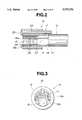
- FIGS. 1 to 3relate to a first embodiment of the invention, FIG. 1 being a schematic arrangement explanatory view of a whole endoscope apparatus;
- FIG. 2is an enlarged explanatory view of a distal part of insertion section of an endoscope according to the first embodiment
- FIG. 3is an explanatory view of the inserting section of the endoscope which is viewed from the side of the distal part of the endoscope according to the first embodiment;
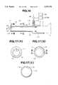
- FIG. 4is a schematic arrangement explanatory view of a whole endoscope apparatus according to a second embodiment of the invention.
- FIG. 5is an explanatory view of the inserting section of the endoscope which is viewed from the side of the distal part of the endoscope according to the second embodiment;
- FIG. 6is an enlarged explanatory view of a distal part of insertion section of an endoscope according to a third embodiment of the invention.
- FIG. 7is an explanatory view of the inserting section of the endoscope which is viewed from the side of the distal part of the endoscope according to the third embodiment;
- FIG. 8is a schematic arrangement explanatory view of a whole endoscope apparatus according to a fourth embodiment of the invention.
- FIGS. 9(a) to FIG. 9(c)are enlarged explanatory views of an inserting section of an endoscope according to a fourth embodiment of the invention, FIG. 9(a) being a view as viewed from an A direction in FIG. 8;
- FIG. 9(b)is a cross-sectional view taken along a line B--B in FIG. 8;
- FIG. 9(c)is a cross-sectional view taken along a line C--C in FIG. 8;
- FIG. 10is a cross-sectional explanatory view of a modification of the inserting section of the endoscope according to the fourth embodiment.
- FIG. 11is a schematic arrangement explanatory view of a whole endoscope apparatus according to a fifth embodiment of the invention.
- FIGS. 12(a) to FIG. 12(c)are enlarged explanatory views of an inserting section of an endoscope according to a fifth embodiment of the invention, FIG. 12(a) being a view as viewed from an A direction in FIG. 11;
- FIG. 12(b)is a cross-sectional view taken along a line B--B in FIG. 11;
- FIG. 12(c)is a cross-sectional view taken along a line C--C in FIG. 11;
- FIGS. 13 and 14are views for the description of a gas-tight structure of a clearance portion between an insertion section and a sheath insertion section of an endoscope according to a fifth embodiment, FIG. 3 being a cross-sectional explanatory view of the sheath inserting section under a condition in which the endoscope is inserted;
- FIG. 14is a cross-sectional explanatory view of the sheath inserting section under a state in which the endoscope is not inserted;
- FIG. 15is a cross-sectional explanatory view showing a modification of the gas-tight structure of the clearance portion
- FIG. 16is a schematic arrangement explanatory view of a whole endoscope apparatus according to a sixth embodiment of the invention.
- FIGS. 17(a) to FIG. 17(c) and FIG. 18are enlarged explanatory views of an inserting section of an endoscope according to the sixth embodiment of the invention, FIG. 17(a) being a view as viewed from an A direction in FIG. 16;
- FIG. 17(b)is a cross-sectional view taken along a line B--B in FIG. 16;
- FIG. 17(c)is a cross-sectional view taken along a line C--C in FIG. 16;
- FIG. 18is a cross-sectional view taken along a line D--D in FIG. 17(b);
- FIG. 19is an explanatory view showing a modification of a gap portion at a sheath distal part according to the sixth embodiment.
- FIG. 20is an arrangement explanatory view showing a first arrangement example of a cleaning mechanism
- FIGS. 21(a), 21(b) and 21(c)are explanatory views showing an arrangement of a three-way activity plug
- FIG. 22is an arrangement explanatory view showing a second arrangement example of a cleaning mechanism
- FIG. 23is an arrangement explanatory view showing a first arrangement example of lens-blur preventing means
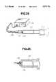
- FIGS. 24 and 25show an example which uses a light emission device as a second arrangement example of the lens-blur preventing means, FIG. 24 being an arrangement explanatory view of the neighborhood of the distal part of the sheath;
- FIG. 25is an arrangement explanatory view showing a whole arrangement of the lens-blur preventing means including the light source device;
- FIG. 26is an arrangement explanatory view showing a modification of the lens-blur preventing means which uses the emitted light of the light source device;
- FIGS. 27 to 37relate to a seventh embodiment of the invention, FIG. 27 being a whole arrangement view of an endoscope apparatus;
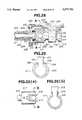
- FIG. 28is a cross-sectional view showing an arrangement in the vicinity of a sheath body
- FIG. 29is a cross-sectional view taken along a line A--A in FIG. 28;
- FIG. 30(a)is a top plan view showing a modification of a sheath mounting structure or arrangement which is different from that in FIG. 28;
- FIG. 30(b)is an enlarged cross-sectional view taken along a line B--B in FIG. 30(a);
- FIG. 31is a top plan view of a sheath body
- FIG. 32is a view as viewed from a direction C in FIG. 31;
- FIG. 33is a perspective view showing a valve unit
- FIGS. 34(a) and 34(b)are explanatory views indicating that the valve unit is capable of being mounted on the endoscope body in a plurality of orientations;
- FIG. 35is a cross-sectional view showing an arrangement of a valve unit
- FIG. 36is an enlarged cross-sectional view taken along a line D--D in FIG. 35;
- FIG. 37is an enlarged cross-sectional view taken along a line E--E in FIG. 35;
- FIG. 38is a cross-sectional view showing an arrangement of an inserting section of an endoscope according to an eighth embodiment of the invention.
- FIG. 39is a top plan view showing an arrangement of the inserting section of the endoscope according to the eighth embodiment.
- FIG. 40(a) and 40(b)show an arrangement of a distal part of the inserting section of the endoscope according to the eighth embodiment, FIG. 40(a) being a front elevation view as viewed from a forward end;
- FIG. 40(b)is a cross-sectional view in an axial direction
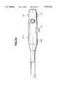
- FIG. 41is a front elevation view showing an arrangement of a distal part of an inserting section of an endoscope according to a ninth embodiment of the invention.
- FIGS. 42(a) and 42(b)are arrangement explanatory views showing an arrangement of the side rearward from a proximal part of the insertion part of the endoscope according to the eighth embodiment;
- FIG. 43is an explanatory view showing a state in which an eyepiece adaptor in FIG. 42(a);
- FIG. 44is an arrangement explanatory view showing a modification of the endoscope in which a disposable portion is separately arranged;
- FIG. 45is an arrangement explanatory view showing an arrangement of a relay lens and a spacing tube within an optical unit of the endoscope according to the eighth embodiment
- FIG. 46is an arrangement explanatory view showing a first modification of the relay lens and the spacing tube
- FIG. 47is an arrangement explanatory view showing a second modification of the relay lens and the spacing tube
- FIG. 48is an arrangement explanatory view showing a third modification of the relay lens and the spacing tube
- FIG. 49is an explanatory view showing a whole schematic arrangement of an endoscope apparatus according to a tenth embodiment of the invention.
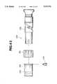
- FIG. 50is a longitudinal cross-sectional view showing the neighborhood of a distal part in the endoscope apparatus according to the tenth embodiment
- FIG. 51is a cross-sectional view taken along a line A--A in FIG. 50;
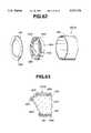
- FIG. 52(a)is a rear view of a forward-end cover member in the endoscope apparatus according to the tenth embodiment
- FIG. 52(b)is a cross-sectional view taken along a line A--A in FIG. 52(a);
- FIG. 53is an exploded perspective view showing a pipe member for sheath and a forward-end cover member in the endoscope apparatus according to the tenth embodiment
- FIG. 54(a)is a longitudinal cross-sectional view of a distal part of an endoscope apparatus according to an eleventh embodiment of the invention.
- FIG. 54(b)is a front elevation view of a transparent plate according to the eleventh embodiment of the invention.
- FIG. 55is a cross-sectional view showing a container which accommodates the transparent plate in the eleventh embodiment of the invention.
- FIG. 56is a longitudinal cross-sectional view of a distal part of an endoscope apparatus according to a twelfth embodiment of the invention.
- FIG. 57is a cross-sectional view showing a container which accommodates the transparent plate in the twelfth embodiment of the invention.
- FIG. 58is a cross-sectional view of an endoscope apparatus according to a thirteenth embodiment of the invention.
- FIG. 59(a)is a cross-sectional view of the endoscope apparatus according to the thirteenth embodiment.
- FIG. 59(b)is a view in which a transparent plate according to the thirteenth embodiment is viewed from the front;
- FIG. 60(a)is a perspective view of a sheath distal part of an endoscope apparatus according to a fourteenth embodiment of the invention.
- FIG. 60(b)is a perspective view of a cover member according to the fourteenth embodiment.
- FIG. 61(a)is a perspective view of a distal part of the endoscope apparatus according to the fourteenth embodiment
- FIG. 61(b)is a cross-sectional view of the distal part of the endoscope apparatus shown in FIG. 61(a);
- FIG. 62is a perspective view in which a distal part of an endoscope apparatus according to a first modification of a blur-preventing sheath is developed.
- FIG. 63is a cross-sectional view of a distal part of an endoscope apparatus according to a second modification of the blur-preventing sheath.
- FIGS. 1 to 3show a first embodiment of the invention.
- FIG. 1is a view showing a schematic arrangement of a whole endoscope apparatus
- FIG. 2is a view showing, in enlargement, a distal part of an insertion section of the endoscope illustrated in FIG. 1
- FIG. 3is a view in which the inserting section of the endoscope is viewed from the side of a forward end.
- the reference numeral 10denotes the endoscope.
- the elongated inserting section 12extends forwardly from an operating unit 11 of the endoscope 10.
- the insertion section 12 of the endoscopeis inserted into a sheath 13.
- a light guide base 14is provided on a side surface of the outer periphery of the operating unit 11.
- An eyepiece 15is provided in rear of the operating unit 11.
- An light emission end surface of the light guide 17is arranged at a forward-end surface 16a of the distal part 16 of the endoscope inserting section 12.
- the light guide 17is adapted to be inserted through the endoscope inserting section 12, the operating unit 11, the light guide base 14 and a light guide cable (not shown), and to be led to a light source device (not shown), to transmit a light from the light source device to the forward end of the endoscope.
- a lens tube 18is inserted into the endoscope inserting section 12 so that a surface of a cover glass 19 which blocks the lens tube 18 is exposed at the forward-end surface 16a of the distal part 16 of the endoscope inserting section.
- An objective lens system 20 and a relay optical system 21are arranged in rear of the cover glass 19. An optical image which is formed by the objective lens system 20 is transmitted, by the relay optical system 21, to the eyepiece unit 15 through the operating unit 11.
- the sheath 13is provided with a feed water channel 22 for leading cleaning liquid (water or the like) to a forward end of the sheath 13 from a Grip for an operator.
- the side of the forward end of the feed water channel 22is provided with a nozzle 23 for blowing the cleaning liquid to the cover glass 19.
- the Grip for the operator of the feed water channel 22is in communication with the feed water line 24 which is formed in the sheath 13.
- cleaning means 25 for feeding the cleaning liquid (water or the like) outis connected to the other end of the feed water line 24.
- the sheath 13has a forward end thereof which is formed, on an inner side thereof, with an edge 13a.
- a slight Gap, or a forward-end clearance 26is defined between the inner surface of the edge 13a ad the forward-end surface 16a of the endoscope insertion section 12.
- the edge 13ais formed into such a predetermined dimension or size as not to narrow a field of view of visual field of observation due to the endoscope 10 (to block the upper portion of the cover glass 19, or the like).
- a slight gap, or an insertion-section clearance 27is defined between the inner surface of the sheath 13 and the endoscope insertion section 12.
- the insertion clearance 27is in communication with the forward-end clearance 26 at the side of the forward end, and is in communication with the suction line 28 formed in the sheath 13, on the grip of the operator.
- suction means 29is connected to the other end of the suction line 28.
- an O-ring 30is provided on the side of the grip of the operator, further from a portion at which the insertion-section clearance 27 and the suction passage 29 are in communication with each other so that air tightness at the side of the grip of the operator of the insertion- section clearance 27 is maintained.
- a white light from the light source device(not shown) is transmitted through the light guide 17, and is outputted toward an objective part, from an outputting end surface of the light guide 17 which is arranged at the forward-end surface 16a of the distal part 16 of the endoscope inserting section 12.
- An imageis transmitted to the operating unit 11 through the cover glass 19 by the objective lens system 20 and the relay optical system 21 so that there can be provided an observation image from the eyepiece 15.
- the cleaning wateris blown, by the cleaning means 25, against the cover glass 19 from the nozzle 23, through the feed water line 24 and the feed water channel 22 which are provided in the sheath 13.
- edge 13ais provided on the inside of the forward end of the sheath 13, it is possible to perform suction in which a suction force is directed to the direction of the cover glass 19 reliably and substantially from the overall periphery, and which is strong and has no nonuniformity.
- the arrangement of the embodimentis such that, under a state in which the sheath is covered on the inserting section of the endoscope, a flow passage for suction is defined by the forward-end clearance defined between the inner surface of the edge formed on the inside of the forward end of the sheath and the forward-end surface of the endoscope inserting section, and the insertion-portion clearance which is in communication with the forward-end clearance and which is defined between the inner surface of the sheath and the outer surface of the endoscope insertion section.
- the forward-end clearanceserves as a nozzle
- the insertion-section clearanceserves as the suction line.
- combination of the endoscope insertion section and the sheathfirst forms the cleaning fluid passage. If the endoscope insertion section and the sheath are disassembled from each other, the fluid line is divided and is exposed. Accordingly, there is no fear that the suction line is clogged by filth or dirt or the like. Moreover, it is possible to easily perform also cleaning and disinfection of the endoscope and the sheath. Thus, it is possible to keep or maintain them clean.
- the sheathmay be of a throwaway type which is to be disposed of after use and replaced by a new one.
- the second embodimentis also arranged substantially similarly to the aforesaid first embodiment.
- the second embodimentis different from the first embodiment in that the arrangement relating to the cleaning is provided on the side of the endoscope body, not on the side of the sheath.
- an elongated inserting section 42extends forwardly from an operating unit 41 of an endoscope 40.
- the endoscope inserting section 42is inserted into a sheath 43.
- the endoscope inserting section 42is provided therein with a feed water channel 44 for leading cleaning liquid (water or the like) from a grip for an operator to a forward end of the endoscope insertion section 42.
- a nozzle 46 for blowing the cleaning liquid against the cover glass 45is provided on the side of the forward end of the feed water channel.
- the grip for the operator of the feed water channel 44is in communication with a feed water line 47 which is provided in the operating unit 41.
- cleaning means 48 for feeding the cleaning liquid (water or the like) outis connected to the other end of the water feed line 47.
- the forward end of the sheath 43is formed, on the inside thereof, with an edge 43a.
- a slight gapthat is, a forward-end clearance 49 is defined between an inner surface of the edge 43a and a forward-end surface 42a of the endoscope insertion section 42.
- the edge 43ais formed to such a predetermined size as not to narrow the field of view of observation due to the endoscope 40 (to block the upper portion of the cover glass 45, or the like).
- an insertion-section clearance 50is defined between the inner surface of the sheath 43 and the endoscope inserting section 42.
- the insertion-section clearance 50is, on the side of a forward end, in communication with the forward-end clearance 49, and is, on the side of a grip for an operator, in communication with a suction line 51 formed in the sheath 43.
- suction means 52is connected to the other end of the suction line 51.
- an O-ring 53is provided on the grip for the operator further from the portion at which the insertion- section clearance 50 and the suction line 51 are in communication with each other so that air tightness is maintained at the grip for the operator of the insertion- section clearance 50.
- the reference numeral 54 in FIG. 5denotes a light guide.
- the cleaning wateris blown, by the cleaning means, against the cover glass 45 from the nozzle 46 through the water feed line 47 and the water feed channel 44.
- the arrangement relating to the cleaningis provided on the side of the endoscope body, it is possible to simplify and small-size the arrangement or structure of the sheath.
- the third embodimentis arranged substantially similarly to the aforementioned first embodiment. However, the third embodiment is different from the first embodiment in that the endoscope inserting section which is inserted into the sheath is further inserted into the sheath to improve suction advantages.
- an inserting section 61 of an endoscope 60is inserted into a first sheath 62.
- the first sheath 62is provided, at a forward end thereof, with a transparent window 63 which cover substantially the entirety of a forward end surface of the endoscope 60 so that the a distal part is made to gas tightness.
- An outward surface of the transparent window 63is a smooth surface having no irregularity.
- the transparent window 63does not generate a step with respect to the forward end of the sheath 62, but is coplanar therewith.
- such coatingmay be applied to the outward surface of the transparent window 63 that dirt is difficult to be adhered to the outward surface of the transparent window 63.
- coating which makes it difficult that dirt is adheredmay be applied to the outward surface of the transparent window 63.
- coating which makes it difficult that a blur occurs or is generatedmay be applied to the inner and outer surfaces of the transparent window 63.
- the endoscope inserting section 61 which is inserted into the first sheath 62is further inserted into a second sheath 64.
- the second sheath 64is provided, at the side of the forward end, with a water feed channel 66 having a nozzle 65, similarly to the first embodiment.
- the grip of the operator of the feed water channel 66is in communication with cleaning means (not shown) through a feed water line (not shown).
- the forward end of the second sheath 64is formed, on the inside, with an edge 64a.
- a slight gapthat is, forward-end clearance 67 is defined between the inner surface of the edge 64a and the forward-end surface 62a of the first sheath 62.
- the edge 64ais formed to such a predetermined size as not to narrow the field of view of observation due to the endoscope 60 (to block the upper portion of the cover window 63 of the first sheath 62, or the like).
- an insertion-section clearance 68is defined between the inner surface of the second sheath 64 and the outer surface of the first sheath 62.
- the insertion-section clearance 68is, on the side of a forward end, in communication with the forward-end clearance 67, and is, on the side of a grip for an operator, in communication with suction means through a suction line (not shown).
- the sheathsare provided double, whereby it is possible to securely prevent the dirt from being adhered to the endoscope forward end.
- the dirtis adhered to the sheath having, at an intermediate portion, the transparent window, the dirt is cleaned and is removed and, thereafter, suction of the water drops or the like is securely preformed.
- the observation field of viewsuperior.
- FIGS. 8 to 10show a fourth embodiment of the invention.
- FIG. 8is a view showing a schematic arrangement of a whole endoscope apparatus
- FIG. 9(a)is a view as viewed from an arrow in an A direction
- FIG. 9(b)is a cross-sectional view taken along a line B--B in FIG. 8
- FIG. 9(c)is a cross-sectional view taken along a line C--C in FIG. 8
- FIG. 10is a cross-sectional explanatory view showing a modification of the endoscope insertion section.
- the fourth embodimentis an example in which an arrangement of the insertion-section clearance and the forward-end clearance for water feed and suction in the first embodiment is modified.
- the other portionsare arranged substantially similar to those of the first embodiment.
- the description of constitutional elements the same as those of the first embodimentwill be omitted.
- an elongated inserting section 72extends forwardly from a body 71 of an endoscope 70.
- the endoscope inserting section 72is inserted into a sheath 73.
- the endoscope body 71has an outer peripheral side surface thereof which is provided therein a light guide base 14.
- An eyepiece unit 15is provided in rear of the endoscope body 71.
- a cover glass 75Arranged on the endoscope 70 is a cover glass 75 which blocks an endoscope optical system which is provided within the inserting section, in the forward end surface 74 of the endoscope inserting section 72. A subject image in front of the cover glass 75 is formed by the endoscope optical system. The formed optical image is transmitted to the eyepiece unit 15.
- the sheath 73is so formed as to comprise the sheath body portion 76, a sheath inserting portion 77 and a sheath distal part 78.
- the endoscope inserting portion 72is inserted into the sheath inserting portion 77.
- the sheath body 76is so mounted as to be fixable with respect to the endoscope body 71.
- the sheath distal part 78is provided therein with an opening 79.
- a light-guide outputting end surface (not shown) of the end surface 74 of the endoscope inserting section and the surface of the cover glass 75are exposed from the opening 79. illumination and observation of the part to be examined are made possible through the opening 79.
- an edge 80 for covering a peripheral edgeis provided in opposed relation to the endoscope inserting-section forward end surface 74.
- a distal-part groove or ditch 81which serves as a forward-end clearance as shown in FIGS. 8 and 9(b) is provided on a part on the inside of the edge 80.
- an inserting-section ditch 82as shown in FIGS. 8 and 9(c) extends from the sheath body 76 to the sheath distal part 78.
- the side of the grip for the operator of the inserting-section ditch 82is in communication with a fluid base 83 which is provided in the sheath body 76.
- the side of the forward end of the inserting-section ditch 82is in communication with the distal-part ditch 81.
- the arrangementmay be such that a gap or clearance 84 is provided between the inner peripheral surface of the sheath inserting section 77a and an outer peripheral surface of the endoscope inserting section 72.
- Feed water means 86 and suction means 87are connected to the fluid base 83 through a three-way activity plug 85 for changing over the lines. Feed out, gas feed, suction and the like can be performed with respect to the endoscope inserting-section forward-end surface 74 by the feed water means 86, the suction means 87 and the feed gas means 88.
- an O-ring 89is provided in the vicinity of the end on the side of the grip of the operator more than a confluence between the inserting-section ditch 82 and the fluid base 83 within the sheath 73. Gas tightness is maintained between the peripheral portion of the sheath inserting-section and the outer peripheral portion of the endoscope inserting section at the side of the grip of the operator of the inserting-section clearance.
- the three-way activity plugis operated to feed the cleaning water from the feed water means 86 into the sheath.
- the cleaning wateris led to the sheath distal part 78 through the inserting-section ditch 82 and the distal-part ditch 81 between the inner surface of the sheath 73 and the endoscope inserting section 72.
- the cleaning wateris blown against the cover glass 75 by the distal-part ditch 81.
- flow of the cleaning water or the like in the endoscope inserting-section forward-end surface 74becomes that as shown by an arrow in FIG. 9(a).
- a three-way activity plug 85is operated to cause the suction means 87 to communicate with the fluid base 83 of the sheath 73.
- Negative pressureis caused to occur on the endoscope inserting-section forward-end surface through the distal-part ditch 81 and the inserting-section ditch 82 to suck the water drops or the like which remain on the surface of the cover glass 75 or the like, from the distal-part ditch 81.
- the arrangementmay be such that the feed gas means 88 is in communication with the interior of the sheath 73 in place of the suction means 87, gas feed is performed through the distal-part ditch 81 and the inserting-section ditch 82, and the water drops or the like which remain on the surface of the cover glass or the like are blown away or off by gas of carbon dioxide gas, compressed air or the like.
- the suctionit is possible to suck not only the water drops which remain on the surface of the cover glass 75 or the like, but also the water drops or the like which remain on the endoscope inserting-section forward-end surface, such as, for example, the outputting end surface of the light guide or the like. Accordingly, it is possible to always maintain the outputting light quantity, the luminous intensity distribution or the like superior.
- the creation and the use of the sheath capable of combining with the prior art endoscopemakes it possible to easily and efficiently the cleaning of the cover glass or the like on the overall periphery of the endoscope inserting-section forward end. Thus, it is possible to sufficiently cope with after-market.
- FIGS. 11 to 15show a fifth embodiment of the invention.
- FIG. 11is a view showing a schematic arrangement of a whole endoscope apparatus
- FIG. 12(a)is a view as viewed from an arrow from a A direction in FIG. 11
- FIG. 12(b)is a cross-sectional view taken along a line B--B in FIG. 11
- FIG. 12(c)is a cross-sectional view taken along a line C--C in FIG. 11.
- the fifth embodimentis an example in which the clearance for water feed and the clearance for suction are provided separately from each other.
- the other portionsare arranged substantially similar to those of the first embodiment.
- the description of constitutional elements the same as those of the first embodimentwill be omitted.
- a feed-water inserting-section ditch 92 and a suction inserting-section ditch 93 serving as inserting-section clearances as shown in FIG. 12(c)extend from the sheath body 94 to the sheath distal part 95, in the inner periphery of the sheath inserting section 91 of the sheath 90 into which the endoscope inserting section 72 is inserted.
- the feed water inserting-section ditch 92 and the suction inserting-section ditch 93have respective sides of a grip of an operator, which are in communication with a water feed base 96 and a suction base 97 which are respectively provided in the sheath body 94, while the feed water inserting-section ditch 92 and the suction inserting-section ditch 93 have respective sides of a forward end, which are in communication with a water-feed distal-part ditch 99 and a suction distal-part ditch 100 which serve as the forward-end clearances provided on the inside of the edge 98 of the sheath distal part 95. Furthermore, an opening 101 is provided in the sheath distal part 95, similarly to the forth embodiment. The endoscope inserting-section forward-end surface is exposed by the opening 101.
- Feed water means 86 and suction means 87are connected respectively to the feed water base 96 and the suction base 97.
- the feed water inserting-section ditch 92, the feed water distal part ditch 99 and the suction inserting section ditch 93, and the suction distal part ditch 100form channels which are air-tight and which are independent of each other. Accordingly, feed water and suction (or feed gas) are made possible to be performed separately or simultaneously by the channels different from each other. At this time, flow of the cleaning water or the like in the endoscope inserting-section forward-end surface comes into that indicated by chain lines in FIG. 12(a).
- FIGS. 13 and 14show a cross-sectional configuration or shape or form of the sheath inserting section 91 under a condition in which the endoscope insertion section 72 is inserted
- FIG. 14shows a cross-sectional configuration or shape or form of the sheath inserting section 91 under a condition prior to the fact that the the endoscope insertion section 72 is inserted.
- the arrangementis such that the sheath inserting section 91 is formed by an elastic member, and an inner diameter of a portion which does not form the feed water inserting-section ditch 92 and the suction inserting-section ditch 93, in the inner periphery of the sheath inserting section 91 (a lateral width in the figure) is so set as to be slightly smaller than an outer diameter of the endoscope inserting section 72.
- the sheath inserting section 91is formed in this manner, whereby, when the endoscope inserting section 72 is inserted, a biasing force as indicated by broken lines in FIG.
- the arrangementmay be such that, as shown in FIG. 15, an elastic material 102, such as rubber or the like, is provided on a portion which is in contact with the endoscope inserting-section outer periphery in the inner periphery of the sheath inserting section 91a, and the sheath inner periphery is in close contact with the endoscope outer periphery by the elastic material 102, so that gas tightness of the feed water inserting-section ditch 92 and the suction inserting-section ditch 93 is maintained.
- an elastic material 102such as rubber or the like
- the endoscope inserting section and the sheathare combined with each other, whereby it is possible to easily form the water feed passage and the suction or feed gas passage independently of each other.
- FIGS. 16 to 19show a sixth embodiment of the invention.
- FIG. 16is a view showing a schematic arrangement of a whole endoscope apparatus
- FIG. 17(a)is a view indicated by an arrow as viewed from an A direction in FIG. 16
- FIG. 17(b)is a cross-sectional view taken along a line B--B in FIG.
- FIG. 17(c)is a cross-sectional view taken along a line C--C in FIG. 16
- FIG. 18is a cross-sectional view taken along a line D--D in FIG. 17(b)
- FIG. 19is an explanatory view showing a modification of the clearance at the sheath distal part.
- the sixth embodimentis a modification of the fourth embodiment.
- the embodimentis an example in which the arrangement of the clearance for the water feed and the suction in the fourth embodiment is modified.
- the description of constitutional portions the same as those of the fourth embodimentwill be omitted.
- a sheath distal part 111 into which the endoscope inserting section 72 is insertedis provided with an opening 112.
- An edge 113is provided which covers a periphery in opposed relation to the endoscope inserting-section forward-end surface.
- a distal-part ditch 114which serves as a forward-end clearance is formed in a part on the inside of the edge 113.
- the sheath inserting section 115is such that an inner diameter thereof is slightly larger than an outer diameter of the endoscope inserting section.
- a clearance 116is defined between the sheath inserting-section inner periphery and an outer periphery of the endoscope inserting section.
- the clearance 116extends to the sheath distal part 111 from the sheath body 117.
- the side of a grip for an operatoris in communication with the fluid base 118 which is provided on the sheath body 117, while the forward-end side is in communication with the distal part ditch 114.
- a projection 119which projects toward the side of the inner periphery of the sheath is provided non a part in the vicinity of the forward end of the sheath inserting section 115.
- a positionis capable of being prescribed so that the positional relationship in a peripheral direction between the sheath inserting section 115 and the endoscope inserting section 72 is always made constant.
- the arrangementmay be such that a plurality of projections 119 are provided, and positioning of the endoscope inserting section 72 with respect to the sheath inserting section 115 is performed.
- the arrangementmay be such that, as shown in FIG. 19, ditches divided into at least two like distal part ditches 114a and 114b are provided in the inside of the edge of the sheath distal part.
- the distal part ditchis divided in this manner, whereby flow of the cleaning water or the like with respect to the cover glass at the forward-end surface of the endoscope inserting section comes into that as shown in arrows in FIG. 19.
- flow of the cleaning water or the like with respect to the cover glass at the forward-end surface of the endoscope inserting sectioncomes into that as shown in arrows in FIG. 19.
- FIG. 20is an arrangement explanatory view showing a first arrangement example of the cleaning mechanism.
- a sheath 120 into which an endoscope inserting section 72 is insertedis so arranged as to be provided with a feed water inserting-section ditch 124 and a suction inserting-section ditch 125 within the sheath inserting section 121, similarly to the aforesaid fifth embodiment.
- the feed water inserting-section ditch 124 and the suction inserting-section ditch 125are arranged such that forward-end sides thereof are in communication with the feed water distal-part ditch 126 and the suction distal-part ditch 127 which are provided in the distal part, while the side of a grip of an operator is in communication with the water feed base 128 and the suction base 129 which are provided in the sheath body 123.
- Feed water means 130is connected to the feed water base 128, while suction means 131 provided with a suction pump is connected to the suction base 129.
- the feed water means 130is provided with a feed water bottle 132 and heating means 133 which is provided on the periphery of the feed water bottle 132 for heating cleaning water within the bottle.
- the water feed means 130 and the sheath 120are connected to each other by the feed water tube 134.
- a three-way activity plug 135is provided in the vicinity of the feed water tube 134, on the side of the sheath, for guiding the cleaning water to the sheath 120 from the feed water means 130.
- the suction means 131 and the sheath 120are connected to each other by a suction tube 136.
- a valve 137 for opening and closing a line of the tubeis provided in the vicinity of the suction tube 136, adjacent to the side of the sheath, for leading drainage or wastewater to the suction means 131 from the sheath 120.
- a communication tube 138extends from the three-way activity plug 135 which is provided on the way of the feed water tube 134.
- the communication tube 138is connected from the valve 137 of the suction tube 136 to a line on the side of the suction means 131.
- FIG. 21(a)shows a state or condition in which the cleaning water does not flow in any of the sheath and the suction tube under an OFF-state.
- FIG. 21(b)shows a state in which the cleaning water flows to the suction tube through a communication tube.
- FIG. 21(c)shows a state in which the cleaning water flows to the sheath.
- a piston 140is arranged within a three-way activity plug body 139.
- the piston 140is biased upwardly by a spring 141.
- the piston 140is in a state illustrated in FIG. 21(a).
- the body 139is provided with bases 142, 143 and 144 to which a tube in communication with the feed water means 130, a tube in communication with the sheath 120 and a tube in communication with the suction means 131 are connected.
- the three-way active plug 135When cleaning of the endoscope inserting-section forward-end surface is performed, the three-way active plug 135 is first operated to communicate the feed water tube 134 and the suction tube 136 with each other. Then, the cleaning water which is heated to the body temperature by the heating means 133 flows out from the feed water means 130, and flows toward the side of the suction means 131 through the communication tube 138. At this time, since the feed water tube per se is the same as the room temperature prior to operation of the three-way active plug, heat is taken away from the cleaning water which remains within the feed water tube 134 prior to the operation, and the cleaning water which flows within the feed water tube 134 immediately after the operation, to the feed water tube so that the temperature of the cleaning water is reduced from the body temperature to the vicinity of the room temperature.
- the temperature of the flowing cleaning watercomes into the temperature the same as that of the cleaning water which is warmed by the body temperature within the feed water bottle 132.
- the three-way active plug 135is operated to cause the feed water tube 134 to communicate with the sheath 120.
- the cleaning waterflows into the cleaning ditch in the sheath 120.
- the cleaning wateris sent to the sheath distal part 122, and is blown against the endoscope inserting-section forward-end surface so that the cover glass or the like is cleaned.
- the cleaning mechanismWith the arrangement of the cleaning mechanism in this manner, it is possible to feed only the cleaning water which is warmed by the body temperature, into the sheath. Since the endoscope inserting section is not cooled by the cool cleaning water, it is possible to prevent the lens of the endoscope from being blurred, making it possible to secure a superior field of view.
- FIG. 22is an arrangement explanatory view showing a second arrangement example of the cleaning mechanism.
- a feed water tube 151 in communication with the feed water mans 130 and a suction tube 152 in communication with the suction means 131are connected to the feed water valve 149 and the suction valve 150 which are provided in a body of a sheath 120.
- a feed water means 130 and a feed water tube 151have respective outer peripheries thereof which are covered by the heating tuber 153 for warming the the cleaning water within the feed water means 130 and the feed water tube 151.
- Heating means 154 for warming the cleaning water to a temperature of the body temperatureis connected to the heating tube 153.
- the heating meansis provided to arrange the cleaning mechanism, it is possible to feed only the cleaning water which is always warmed to the body temperature, to the sheath 120. Thus, it is possible to prevent the lens of the endoscope from being blurred, similarly to the first arrangement example.
- the arrangementmay also be such that, in place of the provision of the cleaning mechanism, the inserting-section distal part is warmed to prevent the lens of the endoscope from being blurred.
- FIG. 23A first arrangement example of the lens blur preventing means is shown in FIG. 23.
- the first arrangement exampleis an example in which the sheath distal part is arranged such that the cleaning-water jetting port in the inserting-section distal part is capable of being heated by an illuminating light.
- An opening 162is provided in the sheath distal part 161 of the sheath 160 into which the endoscope inserting section 72 is inserted.
- a light guide outputting end surface 163 of the endoscope inserting-section forward-end surface and a cover glass 164are exposed from the opening 162. Illumination and observation of a region to be examined are made possible through the opening 162.
- the sheath distal part 161is provided with an edge 165 which covers a peripheral portion in opposed relation to the endoscope inserting-section forward- end surface.
- a distal-part ditch 167which serves as a forward-end clearance is provided in a part of the edge 165 on the inside thereof.
- the distal-part ditch 167is in communication with the clearance 166 which is provided in the inside of the sheath inserting section.
- the cleaning water which is sent from the feed water means into the sheathis adapted to be blown against the endoscope forward-end surface through the clearance 166 and the distal-part ditch 167.
- the sizes of the opening 162 and the edge 165are set such that the illumination light 168 from the light guide outputting end surface strikes against or is applied to a portion of the edge 165 of the opening 162 in the sheath distal part 161.
- the sheath distal partIn the endoscope apparatus in which the sheath distal part is arranged in this manner, a part of the illumination light which illuminates the region to be examined, which is outputted from the light guide outputting end surface 163 impinges against or is applied to a portion of the edge 165 of the opening 162 so that the opening 162 is warmed by the illumination light. Further, by the heat of the illumination light, the cleaning water which jetted from the end of the distal-part ditch 167 and the endoscope inserting-section distal-part is warmed.
- the endoscope inserting-section forward-end surfaceis not cooled by the cool cleaning water, it is possible to prevent the lens of the endoscope from being blurred.
- the outputting light of the light source deviceis used to warm the endoscope distal part prior to the fact that the endoscope is used, whereby it is also possible to prevent the lens of the endoscope from being blurred.
- FIGS. 24 and 25An example which uses the outputting light from the light source device is shown in FIGS. 24 and 25 as a second arrangement example of the lens blur preventing mean.
- the arrangementis adapted to be arranged such that the light source device at this time is used to connect the outputting end of the light guide cable which is connected to the light source device so that the endoscope distal part is warmed by a white light from the light source device.
- An openingis provided in a sheath distal part 171 of a sheath 170 into which the endoscope inserting section 72 is inserted, similarly to the aforementioned embodiment.
- a base 172is so provided as to protrude from the opening.
- a connecting portion 174 on the side the outputting end, of the light guide cable 173 which is connected to the light source device 175is connected to the base 172.
- a white light from the light source device 175is applied to the endoscope inserting-section forward-end surface 74 through the light guide cable 173. It is possible to warm the distal part of the endoscope by the white light from the light source device. Thus, it is possible to prevent the lens of the endoscope from being blurred which causes the field of view of the endoscope to be disturbed.
- the distal partis warmed to prevent the lens from being blurred. Accordingly, efficiency is superior in view of time. Further, special or specific equipments such as a scope heater and the like and expensive devices are not required or unnecessary as lens blur preventing means. Thus, it is possible to prevent the equipments within an operation ground or field from increasing in number. No especial economic burden is also applied to the operator.
- the arrangementmay be such that, as shown in FIG. 26, a tube 176 which is made of heat conduction material and whose distal part is blocked is arranged within the sheath inserting section.
- the arrangementmay be such that the tube is first warmed by the illumination light, and the endoscope distal part and the endoscope inserting section are warmed by the warmed tube.
- FIGS. 27 to 37show a seventh embodiment of the invention.
- an endoscope apparatus 201is so arranged as to comprise a rigid endoscope 202, a sheath 203 over which the rigid endoscope 202 is covered, a light source device 204 for supplying an illumination light to the rigid endoscope 202, a valve unit 206 detachable mounted on an endoscope body 205 of the rigid endoscope 202 in a plurality of orientations, and feed water means 209 and suction means 210 connected respectively to a feed water tube 207 and a suction tube 208 which are connected to the valve unit 206.
- the rigid endoscope 202is so arranged as to comprise a rigid endoscope inserting section 211 which is formed by an elongated metal pipe or the like, a large diameter endoscope body 205 formed at a rearward end of the endoscope inserting section 211, and an eyepiece unit 212 which is provided at a rearward end of the endoscope body 205.
- a light guide(not shown) for transmitting an illumination light is inserted into the endoscope inserting section 211.
- the light Guidehas a rearward end thereof which reaches a light guide base 213 which is provided on the endoscope body 205.
- the light Guide base 213is connected to the light source device 204 through the light Guide cable 214.
- the illumination light due to the light source device 204is transmitted by a light guide (not shown) within the light cable 214 and within the rigid endoscope 202.
- the illumination lightis outputted forwardly from a forward-end outputting surface which is mounted on an illumination window (not shown) in a forward end surface 211a of the endoscope inserting section 211.
- a subject such as an illuminated affected or diseased part or the likeis formed to a focal plane by an objective lens (not shown) which is mounted on an observation window formed adjacent to the illumination window in the forward end surface 211a.
- An optical image thereofis transmitted rearwardly by an image guide such as a relay optical system (not shown) or the like which is inserted into the endoscope inserting section 211.
- an image guidesuch as a relay optical system (not shown) or the like which is inserted into the endoscope inserting section 211.
- the sheath 203which is detachably mounted on the endoscope inserting section 211 and the endoscope body 205 has a sheath inserting section 216 which covers the endoscope inserting section 211, and a sheath body 217 which is formed at the rearward end of the sheath inserting section 216 and which covers the endoscope body 205.
- a line 218is formed or defined between the sheath inserting section 216 and the endoscope inserting section 211.
- the side of a grip of an operatoris kept in gas tightness by an O-ring between the sheath body 217 and the endoscope body 205.
- the line 218has the forward end side thereof which is in communication with the nozzle unit 221 which is provided on the sheath distal part 220.
- the side of the grip for the operator of the line 218 within the sheath 203is in communication with one or more bases 223 and 224 which is or are provided in the sheath body in the vicinity of the side of the forward end of the O-ring 219.
- the valve unit 206is detachably mounted on the endoscope body 205 in a plurality of orientation and is regulated in position by the sheath body 217.
- the feed water tube 207 and the suction tube 208are connected to the base 223 of the sheath 202 tough the mounting portion 225 of the valve unit 206.
- a cap 226is mounted on the base 224 on which the mounting portion 225 is not mounted, of the bases 23 and 224 which are provided on the sheath body 217, to block an opening of the base 224.
- narrow ditches 234 and 245 and a generally U-shaped ditch 233 having a wide width portion 231 slightly wider in width than a diameter of the light guide base 213 of the rigid endoscope 202 and a narrow width portion 232 which is located at the opening end and which is slightly smaller in width than the diameter of the light guide base 213are provided alternately, whereby a pair of pawls 236 ad 237 are formed.
- the light guide base 213 of the rigid endoscope 202is put between the pair of pawl portions 236 and 237 so that the rigid endoscope 202 is prevented from being rotated or from slipping down or off longitudinally.
- the pawl portions 236 and 237are formed by the generally U-shaped ditch 233 and the narrow ditches 234 and 235 which are provided in the sheath body 217, but may be arranged such that, as shown in FIG. 30(a) and 30(b), the light guide base 213 of the rigid endoscope 202 is fixed by the generally U-shaped pawl member 239.
- a receipt 241 for positioning, in mounting, the valve unit 206 ad for restricting or limiting the valve unit 206 such that a position of the valve unit 206 does not slip down or offis provided in rear of the lower side of the sheath body 217.
- the valve unit 206is fitted such that the whole opening 242 in the valve unit 206 surrounds the endoscope body 205, the edge 243 of the opening 242 in the valve unit 206 is fitted in the receipt 241 so that rotation of the valve unit 206 is limited.
- valve unit 206In connection with the above, in order to facilitate understanding of the outer configuration or outer shape of the valve unit 206, the valve unit 206 is shown by broken lines and hatching in FIGS. 31 and 32.
- two of the pawls 245(refer to FIG. 33) which are provided at four (4) locations symmetrically on the left- and right-hand sides and longitudinally on both ends of the edge 243 in the valve unit 206 are fitted respectively in the pair of ditches 244 which are provided on a portion of the receipt 241 symmetrically with respect to the right-and left-hand sides, to limit that the valve unit 206 slips down or off axially of the rigid endoscope 202.
- FIG. 34(a)shows a view for viewing, from the lower side of the rigid endoscope 202, a state or condition in which the valve unit 206 is mounted on the endoscope body 205.
- FIG. 34(b)shows a view for viewing, from the lower side of the rigid endoscope 202, a state or condition in which the valve unit 206 is mounted on the endoscope body 205.
- FIG. 34(b)shows a view for viewing, from the lower side of the rigid endoscope 202, a state or condition in which the valve unit 206 is mounted on the endoscope body 205.
- FIG. 34(b)shows a view for viewing, from the lower side of the rigid endoscope 202, a state or condition in which the valve unit 206 is mounted on the endoscope body 205.
- FIG. 34(b)shows a view for viewing, from the lower side of the rigid endoscope 202, a state or condition in which the valve unit 206 is mounted on the endoscope body 205.
- the arrangementmay be such that, in FIG. 34(a) for example, a ditch in which the pawl 245 of the valve unit 206 can be fitted even in a position in front of the receipt 241, in addition to the ditch 244 in the receipt 241 which is provided in the body of the sheath 203 so that the valve unit 206 is detachably mounted on a plurality of positions in the longitudinal direction of the sheath 203.
- the valve unit 206can be mounted on a position and an orientation which are further easy to operate.
- the degree of freedom of selectioncan be widened.
- FIG. 35, FIG. 36 and FIG. 37are cross-sectional views showing a structure of the valve unit 206 and the mounting portion 225.
- the valve body 206ais provided therein with a feed water lateral hole 246 and a section lateral hole 247 which are vertically arranged and which are so bored as to pass through horizontally, a feed water longitudinal hole 248 and a suction longitudinal hole 249, which are vertically bored so as to be intersected with the pair of lateral holes 246 and 247.
- the water feed longitudinal hole 248is provided therein with a spring retainer 250 and a water feed tube fastener 251 are provided in the feed water longitudinal hole 248, and a spring retainer 252 and a suction tube fastener 253 are provided in the suction longitudinal hole 249
- a water feed button 227which is vertically movably fitted in the water feed longitudinal hole 248 is so provided as to be pushed upwardly with respect to the spring retainer 250 by a spring 254.
- a lateral shank 255is provided at a lower end of the feed water button 227 so as to be positioned at the lower side of the feed water tube 207. The arrangement is such that, in keeping with the fact that the feed water button 227 is pushed upwardly by the spring 254, the lateral shank 255 urges the feed water tube 207 against the feed water tube fastener 251 so that the tube 207 is crushed and thus, the line 256 within the tube 207 is closed.
- the feed water button 227is pushed downwardly by a large or great force which overcomes the spring 254, whereby an upper surface of the water feed button 227 is moved to a position indicated by two-dot-and-chain line in FIGS. 35 and 36.
- a force by which the feed water tube 207 is urged upwardlyis reduced or weakened.
- the water feed tube 207is rounded by the elasticity of the feed water tube 207 per se.
- the line 256 within the tube 207is opened. The water begins to flow. Furthermore, an amount through which the feed water button 227 is pushed downwardly is adjusted whereby the amount of feed water can also be adjusted.
- the suction tube 208is arranged as follows. That is, the suction button 228 is pushed downwardly by such a large or great force as to overcome the spring 254a.
- the lateral shank 255areduces or weakens a force which urges the suction tube 208 upwardly, to open the suction line 257 within the suction tube 208.
- an upper surface of the suction button 228 and the lateral shank 255aare moved to a position indicated by two-dot-and- chain line in FIGS. 35 and 37. It is possible to turn ON/OFF the suction and to adjust the quantity of suction.
- the valve unit 206is possible to be detachably mounted on the endoscope body 205, and the mounting orientations can be selected as shown in FIGS. 34(a) and 34(b). Accordingly, an operator can mount the endoscope in the orientation easy to operate and can operate the endoscope. Further, in case where operation is not required, the endoscope can be dismounted to perform the endoscope examination.
- the seventh embodimenthas a merit that operability can be improved more than the case where the valve unit is fixed. Accordingly, even for an operation in which delicate operation is required and for an operation which extend to a long period of time, the endoscope is easy to be had.
- the button operation of the valve unit 206can easily be performed. The proceeding of the operation can smoothly be performed. Moreover, fatigue of the operator can be reduced.
- a structure in which the valve unit is detachably mounted on the endoscope bodyhas been described (the position regulation mechanism is provided on the sheath body).
- a structuremay be such that the valve unit is detachably mounted on the sheath body.
- a structuremay be such that the valve unit is detachably mounted on both of them.
- FIGS. 38 to 40show an eighth embodiment of the invention.
- the eighth embodimentshows an arrangement example of the endoscope of disposable type in which, after the endoscope as been used, the endoscope is cancelled.
- An endoscope 301is so arranged as to comprise a rigid elongated inserting section 302 which is inserted into a body cavity or the like, and an endoscope body 303 which is connected to a distal part of an inserting section 302.
- the body 303is made of resin.
- the inserting section 301is provided, within an outer tube 302a of the inserting section, with an optical unit 306 including a relay lens 304 and an objective lens 305 and an illumination optical system 307 for transmitting the illumination light so arranged as to bundle plastic fiber, glass fiber or the like around an outer periphery of the optical unit 306, to the distal part.
- the optical unit 306is arranged with the relay lens 304 being determined in intervals by interval tubes 308.
- An objective lens 305is arranged at a distal part. These relay lens 304 and objective lens 305 are so arranged as to be housed within a pipe-like inner tube 309.
- the illumination optical system 306has a proximal end is arranged such that disconnected or disjointed fibers are caulked so as to be put together into one by a caulking member 310.
- the caulking member 310is provided with a flange 310a for fixing the proximal end of the illumination optical system 307 to the body 303.
- a distance with respect to a light guide cable outputting end surface which is connected to a light guide base 11is adapted to be maintained constant by the flange 310a.
- it is desirable that an inputting end surface of the illumination optical system 307is polished in case of glass, is polished after fusion in case of plastics, or the like, to improve inputting efficiency.
- the body 303, and the inserting-section outer tube 302a, the optical unit 306 and the illumination optical system 307are maintained water-tightly respectively by O-rings 312, 313 and 314.
- the body 303is adapted to be capable of being split into a pair like 303a and 303b in view of a manufacturing problem, and is integrated by ultrasonic fusion, adhesion or the like.
- a chamber 315is formed water-tightly in the interior by the O-rings 312, 313 and 314 and the body 303.
- a base 316 which is in communication with the chamber 315is provided in a side of the body 303, as shown in FIG. 39.
- a tube which performs feed water, feed gas, suction or the like for cleaning the objective lens 305can be connected to the base 316.
- FIG. 40(a) and FIG. (b)A detailed arrangement of the distal part of the inserting section 302 is shown in FIG. 40(a) and FIG. (b).
- the objective lens 305is exposed to the forward-end surface of the inserting section.
- a distal part of the inner tube 309 which covers the optical unit 306is bent or folded approximately 90° along the end surface of the inserting section.
- a packing 317is provided between the folded portion of the inner tube 309 and the objective lens 305 so that the water tightness of the optical unit 306 is maintained or retained.
- a spring retainer 318is provided at the proximal end of the optical unit 306, as shown in FIG. 38.
- a spring 319is engaged between the spring retainer 318 and the body 303.
- the relay lens 304is pushed forwardly by a biasing force of the spring 319, and a force thereof is transmitted to the objective lens 305.
- the packing 317is urged against the inner tube 309. Thus, water tightness is kept or maintained
- an illumination optical system 307is arranged around the optical unit 306.
- a portion in which the fibers are partially lackingis provided whereby a clearance portion 320 is provided.
- a canopy top 321which projects in the form of an L-shape so as to be opposed against the opening position of the clearance 320 is formed by the fact that the distal part of the inserting-section outer tube 302a is worked or processed, and is provided.
- a feed water or suction passageis defined by the clearance 320.
- a jetting nozzle directed toward the objective lensis formed by the portion of the canopy top 321.
- feed water liquid for cleaningis fed to the endoscope through the feed water tube by a pressurizing pump, a roller pump or the like. If the water feed tube is connected to the base 316 so that water is fed upon cleaning, the feeding water which enters the chamber 315 from the base 316 passes through the clearance between the inserting-section outer tube 302a, and the inner tube 309 of the optical unit 306 and the illumination optical system 307 travels toward the clearance 320 which opens at the distal part. Thus, the feeding water is led to the distal part. As shown by the arrows in FIG.
- the feed water liquid which flows through the clearance 320is bent in water feeding direction by approximately 90° or more by the canopy top 321, and is jetted toward the surface of the objective lens 305.
- the canopy top 321is bent in water feeding direction by approximately 90° or more by the canopy top 321, and is jetted toward the surface of the objective lens 305.
- the arrangementmay also be such that the suction means is connected to the base 316 so that water drops or the like remaining on the surface of the objective lens 305 or the like is sucked through the clearance 320.
- the clearances between the inserting-section outer tube 302a, the optical unit 306 and the illumination optical system 307are used as the passages for water feed and the like, whereby it is possible to easily form the cleaning line. Further, it is not required or it is not necessary to additionally provide the nozzle, the tube and the sheath. Even in the structure having the objective lens cleaning function, it is possible to reduce the cost, and the assembling can also be improved.
- the ninth embodimentis a modification in which the arrangement of the inserting section of the endoscope in the eighth embodiment is modified.
- the ninth embodimentis an example in which a plastic mold is used in place of the fibers, as the illumination optical system, to form the ninth embodiment.
- the other fundamental or principle arrangementis similar to that of the eighth embodiment.
- an optical unit 306 and an illumination optical system 325made of a plastic mold and having a cross-section which is a crescent shape in cross-section so as to surround the optical unit 306 are incorporated into the interior of the outer tube 302a of the inserting section 302. Further, a clearance 326 is defined between the inserting-section outer tube 302a and the optical unit 306 and the illumination optical system 325.
- a canopy top 327 for changing or altering an orientation of water flow which is sent from the clearance 326is provided at a position which is opposed against the opening in the one clearance 326. In this connection, in FIG. 41, the canopy top 327 is provided only on the one clearance 326. However, the canopy tops may be provided correspondingly respectively to both clearances 326.
- the sent feed water liquidpasses through the clearance 326, and is led to the distal part.
- the sent feed water liquidis discharged from the opening in the clearance 326, and is changed in orientation by the canopy top 327.
- the sent water liquidis jetted toward the surface of the objective lens 305.
- the arrangement of the ninth embodimentcan produce advantages similar to those of the eighth embodiment. Since the plastic mold is used in the illumination optical system, a step of bundling the fibers upon assembling is dispensed with as compared with the eighth embodiment. Thus, operation is simple, and it is possible to further improve assembling ability or performance.
- FIG.42(a) and FIG. 42(b)show the arrangement of the endoscope 301 in rear of the inserting-section proximal end.
- the lens within the optical unit, the illumination optical system, the body or the likeis formed by the plastics in order to come into a disposable type, so that an attempt is made to reduce the cost.
- the plasticsare used in the lens, whereby aberration occurs.
- the embodimentis arranged such that the glass lens portion is made to a reusable type and is provided on the side of the rear end of the endoscope body, and the body and the inserting section of the plastic lens portion are made to a reusable type.
- the endoscope body 303 and the inserting section 302, and the eyepiece adaptor 330are formed separately from each other.
- An optical system having a glass lensis arranged within the eyepiece adaptor 330, and a focus ring 331 for focusing is provided within the eyepiece adaptor 330.
- a cam groove or ditch 332is provided in a connection of the end of the eyepiece adaptor 330 with respect to the endoscope body 303.
- a knob 333is provided laterally adjacent to the cam ditch 332.
- a projection 34 which projects laterally and which is engaged with the cam ditch 332is provided on the proximal end of the endoscope body 303.
- the projection 334 of the endoscope body 303is engaged with the cam ditch 332 in the eyepiece adaptor 330 so that the proximal end of the endoscope body 303 is fitted therein.
- the knob 333is clamped to rotate the eyepiece adaptor 330.
- the projection 334is fixed to the cam ditch 332 in the projection 334.
- FIG. 42(b)As an arrangement which connects the eyepiece adaptor 330 and the endoscope body 303 to each other, an arrangement which connects them to each other by the cam ditch is considered as shown in FIG. 42(b) and,in addition thereto, various dismounting mechanisms which use snap fit, a screw or a magnetic force, and the like are considered.
- FIG. 43An exploded view of the eyepiece adaptor 330 is shown in FIG. 43.
- the arrangement of the eyepiece adaptor 330is such that, when the knob 333 on the lateral side is disengaged, the connection 335 having therein the cam ditch 332 and the focus ring 331 can be dismounted from the adaptor body 336.
- the eyepiece adaptor 330upon cleaning after having been used in the operation or the like, it is possible to disassemble the eyepiece adaptor 330, whereby it is possible to easily or simply clean various parts of the eyepiece adaptor 330 every nook and corner. Accordingly, handling is simple and convenient.
- the endoscope body and the inserting section and the eyepieceare so formed as to be separate form each other, and only the body and the inserting section are disposable.
- the disposable portionsit is possible to arrange the disposable portions at low cost. It is realized to make the rigid endoscope to the arrangement which is more suitable for a disposable type.
- the camera head 338is detachable with respect to the proximal end of the endoscope body 303.
- the camera head 338has an eyepiece unit 339 having a cam groove or ditch whose arrangement is similar to that of the eyepiece adaptor 330.
- the camera head 338is provided therein with an image pickup optical system and an image pickup element.
- the camera head 338is connected to a camera control unit for performing image-signal processing, through the signal cable 340 which extends from the rearward end thereof.
- the relay lens 304has a diameter thereof which is the same as the outer diameter of the spacer tube 308, and comprises a large diameter portion 341 in contact with the inner tube 309, and a reduced diameter portion 342 having a diameter thereof smaller than the large diameter portion 341.
- An outer diameter of the reduced diameter portion 342comes into one which is capable of being press-fitted or interfitted with respect to the inner diameter of the spacer tube 308.
- the spacer tube 308is interfitted in the reduced diameter portion 342 of the relay lens 394, whereby the relay lens 304 and the spacer tube 308 are assembled with each other.
- the relay lens 304is provided, at both ends thereof, with the reduced diameter portion 342. Accordingly, the relay lens 304 ad the relay lens are combined with each other subsequently like blocks, whereby it is possible to easily assemble the relay optical system.
- a relay optical unit in which all the relay lens 304 and the spacer tube 308 are assembled with each other to make a columnar shapeis integrally inserted into the inner tube 309.
- the relay lens and the spacer tubeare arranged in this manner.
- the spacer tube and the relay lensare so assembled with each other as to be put into the inner tube carefully one by one.
- the interior relay lens and spacer tubeare first integrally assembled with each other exteriorly and, subsequently, the integrated relay optical system is inserted into the inner tube so that it is possible to assemble the optical unit.
- FIG. 46shows a first modification of the relay lens and the spacing tube.
- the relay lens 345is provided, on the sides thereof, with four (4) ribs 346 in sum, which project in the form of a columnar shape, at positions which are opposed against each other at both ends thereof.
- the spacer tube 347is provided with a cam ditch 348 with which the ribs 346 are engaged. The arrangement is such that, when the relay lens 345 and the spacer tube 347 are connected to each other, the rib 346 is engaged with the cam ditch 348 and is fixed thereto.
- the rib 346 of the relay lens 345 and the cam ditch 348 of the spacer tube 347are engaged with each other, and are successively assembled with each other.
- the relay optical system unitit is possible to easily assemble the relay optical system unit.
- FIG. 47shows a second modification of the relay lens and the spacer tube.
- the relay lens 350is provided, at both ends thereof, with engaging ditches 351 in the form of an orbit. Meanwhile, the spacer tube 352 is formed with a pawl 353 which is engaged with the engaging ditch 351. By these elements, a connecting mechanism of a snap fit time is formed. The arrangement is such that, when the relay lens 350 and the spacer tube 352 are connected to each other, the pawl 353 is engaged with the engaging ditch 351 and is caught thereby so that the pawl 353 is fixed.
- the relay optical systemWhen the relay optical system is assembled, as the relay lens 350 is inserted into the spacer tube 352, the pawl 353 is caught at the engaging groove 351 so that the relay lens 350 and the spacer tube 352 are fixed. Similarly, the relay lens 350 and the spacer tube 352 are successively assembled with each other, whereby it is possible to easily assemble the relay optical system unit. In the present example, because of the connecting mechanism of snap fit type, assembling is more simplified.
- FIG. 48shows a third modification of the relay lens and the spacer tube.
- the relay lens 355is formed with a large diameter portion and a reduced diameter portion, similarly to the arrangement illustrated in FIG. 45.
- Male threads 356are provided in the reduced diameter portion at both ends of the relay lens 355.
- the spacer tube 357has an inner periphery thereof which is provided with female threads 358. The male threads 356 are threadedly engaged with the female threads 358 so as to be fixed.
- the male threads 356 of the relay lens 355are screwed into the female threads of the spacer tube 357 so that the relay lens 355 and the spacer tube 357 are connected to each other. Similarly, the relay lens 355 and the spacer tube 357 are successively connected to each other. Thus, it is possible to easily assemble the relay optical system unit.
- the relay optical system unitcomprising relay lenses and spacer tubes, can be assembled easily and in a short time, thereby enabling the apparatus to be constructed at low costs.
- an endoscopecan be constructed at low costs and in a structure having a satisfactory assembling performance. Further, the passage or nozzle for cleaning can be formed in a simple structure, thereby providing the apparatus with an objective cleaning function easily and at low costs. Thus, the apparatus can have a structure suitable for throwaway-type uses.
- FIGS. 49 through 53A tenth embodiment of the present invention will be described with reference to FIGS. 49 through 53.
- FIG. 49schematically shows the overall construction of the endoscope apparatus.
- numeral 401indicates a rigid endoscope
- numeral 402indicates an anti-fogging sheath device to be attached to the rigid endoscope 401.
- the rigid endoscope 401comprises an endoscope body 404 equipped with an eyepiece section 403 containing an eyepiece, and an endoscope insertion section 405 consisting of a rigid straight tube.
- the endoscope body 404is provided with a connector 407 for connecting it with a light guide cable 406.
- the light guide cable 406is connected to an illuminating light source device 408.
- the anti-fogging sheath device 402comprises a sheath body 411 to be fitted onto the endoscope body 404 of the rigid endoscope 401, and a sheath insertion section 412 consisting of a cover tube coaxially fitted onto the endoscope insertion section 405 of the endoscope 401.
- the inner diameter of the sheath insertion section 412is larger than the outer diameter of the endoscope insertion section 405.
- a fluid supply duct 413is defined between them.
- the duct 413communicates with a nozzle section 436 which is formed at the forward end of the sheath insertion section 412 in the manner described below.
- a ring-shaped seal member 414is attached to the inner surface of the sheath body 411.
- the seal member 414is closely fitted into the gap between the inner surface of the sheath body 411 and the outer surface of the endoscope 404 to airtightly or fluid-tightly stop the section of the duct 413 nearer to the operator.
- the seal member 414is formed, for example, of an elastic material.
- This seal memberconsists of a silicon rubber member, elastic O-ring member, etc.
- an elastic synthetic resinis preferable for its material.
- one or a plurality of basesare provided at positions nearer to the forward end than the position of the seal member 414 in such a way as to communicate with the duct 413.
- two or more basesare provided.
- One baseis connected to a feed water tube 416, and the other base is connected to a suction tube 417.
- the feed water tube 416leads to a feed water means (a feed water device) 418, and the suction tube 417 leads to a suction means (a suction device) 419.
- the fluid passages of the feed water tube 416 and the suction tube 417are selectively switched through operation of a feed water button 422 and a suction button 423 provided on a valve unit 421, whereby the water feeding or suction through the tubes 416 and 417 can be turned on and off, and, further, the flow rate therein can be adjusted.
- the water feeding operation and sucking operation for the duct 413can be controlled.
- the valve unit 421is detachably mounted on the sheath body 411.
- a light guide(not shown) is provided within the endoscope 401.
- This light guideleads illuminating light, which is led through the light guide cable 406, to an illumination window formed in a forward end surface 425 of the endoscope, thereby illuminating the section to be observed in the body cavity.
- the endoscope forward end surfacehas an observation window having an objective lens and formed beside the illumination window.
- the endoscopecontains an observed-image transmission optical system (not shown) for transmitting an image of the viewing field formed by the objective lens of the observation window. The image transmitted through the transmission optical system can be observed through the eyepiece section 403.
- the endoscope 401 used in this embodimentis not restricted to a rigid type one. Any type of endoscope, e.g., soft type, electronic type, etc., is applicable to this embodiment.
- the sheath insertion section 412 of the anti-fogging sheath device 402is formed by joining the forward end of a sheath pipe member 431 to a forward end cover member 432 having the same outer diameter as the sheath pipe member 431.
- the forward end cover member 432consists of an integrally molded, short cylindrical member generally having a bottom and formed of a resin which is optically transparent. Its flat bottom section (central section) constitutes a transparent observation window 433.
- Formed in the periphery of the observation window 433is a cylindrical flange section 434 slightly protruding forward beyond it. It is desirable that the inner diameter of the flange section 434, formed as a cylinder, be not so large as to interfere with the viewing field of the endoscope 401.
- the forward end cover member 432that end where the flange section 434 is formed will be referred to as the forward end, and the end opposite thereto as the base end. At least one hole 435 not reaching the flange section 434 and directly communicating with the duct 413 extends from the base end. In this embodiment, four holes 435, upper, lower, right and left ones, are provided.
- each of the holes 435has at its forward end an opening which is bent toward the central axis of the forward end cover member 432, thereby forming a nozzle section 436 extending from the base end and bent at right angles at the forward end.
- the forward end opening of the nozzle sectionis directed toward the surface of the observation window 433 and connected thereto.
- a plurality of short rearward projections 437are formed in the rear periphery of the forward end cover member 432.
- the radial thickness of the projections 437is equal to the wall thickness of the sheath pipe member 431.
- the projections 437 of this embodimentare arranged at equal intervals between the holes 435, in an alternate order.
- the number of projections 437is not limited to four. It may also be one, two or three or more.
- the holes 435 and the projections 437have a substantially rectangular longitudinal sectional configuration, their inner and outer sides are in the circumference of the same circle having its center in the central axis of the forward end cover member 432.
- the circlehas a size which coincides with the inner diameter circle of the sheath pipe member 431.
- the right and left sides of the holes 435 and the projections 437are flat, they exhibit a wedge-like configuration smaller on the inner side when seen in cross section.
- the diameter of the circle connecting the inner sides of the projections 437is limited to that in the above example. However, it is necessary for the diameter to be at least somewhat larger than the outer diameter of the endoscope insertion section 405 fitted into the sheath insertion section 412.
- a plurality of cutouts 438are formed at equal intervals at the forward end of the sheath pipe member 431 to be connected to the forward end cover member 432, the cutouts 438 having a configuration corresponding to that of the projections 437 for butt-joint.
- the forward end cover member 432 and the sheath pipe member 431are coaxially butted against each other so as to fit the projections 437 into the cutouts 438.
- the forward end cover member 432 and the sheath pipe member 431are of necessity coaxially aligned with each other. In this way, at least a pair of protrusion 437 and cutout 438 are fitted together and the joint between the forward end cover member 432 and the pipe member 431 is secured by adhesion, fusion, etc.
- the resin of which the forward end cover member 432 is formedis a transparent one, for example, methacrylic resin (PMMA) or polycarbonate resin (PC). Further, an anti-fogging processing is performed at least on the transparent portion of the observation window 433 of the forward end cover member 432.
- PMMAmethacrylic resin
- PCpolycarbonate resin
- the anti-fogging processingmay consist, for example, of resin coating, pellet mixing, or sheet-like member gluing. It is desirable that this anti-fogging processing be performed on both sides of the observation window portion 433 in the forward end cover member 432.
- the anti-fogging processingwill be described in more detail.
- Examples of the coating processinclude vacuum deposition, dipping, spin coating, etc. In vacuum deposition, a high-polymer-type material having hydrophilic and hydrophobic groups is evaporated on a transparent member in a vacuum to form a film. In dipping, such a transparent member is immersed in a processing liquid to form an anti-fogging layer.
- the processing liquid materialis dripped onto a rotating transparent member to form an anti-fogging layer.
- a surface active agentis mixed in pellets of a plastic molding material; after molding, a film of hydrophilic groups is formed on the surface of a transparent member.
- an anti-fogging film in the form of a thin sheet, prepared by the coating or pellet mixing,is glued to the surface of a transparent member.
- an anti-fogging coat or water absorptive coatis obtained. Due to the anti-fogging processing, fine droplets of water adhering to the surface of a transparent member, which water, if allowed to remain in the form of droplets, would cause fogging, are dispersed in a uniform, film-like state to cover the surface of the transparent member, thereby removing or preventing fogging.
- an observation window 433 of a forward-end cover 432 of the sheath device 402is closely bonded to an endoscope end surface 425 of an endoscope insertion section 405 provided with an observation window and an illumination window next to each other, as shown in FIG. 50.
- the endoscope insertion section 405is located on a plurality of projections 437 of a forward-end cover 432 or on the inner surface of a pipe 431.
- the inner surface of the observation window 433 subjected to the defogging treatmentis watertightly placed on the endoscope end surface 425.
- a cleaning liquidblows against the observation window 433 to remove the waterdrops or dirt. More specifically, a feed water button 422 of a valve unit 421 is depressed to perform the feed liquid operation so as to allow a cleaning fluid flowing through a pipe 413 formed between the endoscope insertion section 405 and the sheath insertion section 412 to inject into the outer surface of the observation window through a nozzle 436. After cleaning, the fluid, such as waterdrops, remaining on the outer surface of the observation window 433 can be removed by means of the suction by depressing a suction button 423 of the valve unit 421 or by means of gas fed from other feed means through the nozzle 436.
- Such an operationcan be performed while the endoscope remains within the body. Even when the endoscope stained with blood, or the like, is cleaned, it can be prevented from fogging, thereby ensuring a 100% clear vision and shortening an operation time without requiring the removal of the endoscope 401 from a body cavity.
- the projections 437 of the forward-end cover 432are fit into notches 438 of the pipe 431, thereby ensuring reliable and simple bonding of both components.
- the forward-end cover 432 provided with the projections 437is bonded to the thin-walled pipe 431 provided with the notches 438, thereby guaranteeing the bonding strength.
- the inner edges of holes 435 and a flange 434 of the forward-end cover 432are aligned along the axis of the insertion section, and thus, the cover 432 can be easily released from a mold when formed.
- This embodimentshows that a sheath provided with a defogging-treated transparent portion is attached to the front surface of the endoscope observation window and can be easily replaced by a new one when the old sheath is no longer effective in protecting the observation window from fogging, thus ensuring 100% defogging effects.
- the sheath device of this embodimentis simple in construction, thereby easily obtaining an inexpensive endoscope apparatus free from fogging.
- the nozzleis formed at the forward-end cover of the sheath, and the endoscope insertion section and the sheath are simply combined to form a cleaning fluid passage easily.
- the observation windowis cleaned through this cleaning nozzle so as to remove dirt or eliminate fog.
- the cleaning fluid passageis formed only when the endoscope insertion section and the sheath are combined. A suction passage is thus free from being clogged with dirt, or the like, and the sheath is detached from the endoscope insertion section so that the endoscope and the sheath can be easily cleaned and sterilized, thus keeping them clean.
- the eleventh embodimentcan be accomplished by modifying the construction of the forward end of the insertion section of the defogging sheath device shown in the tenth embodiment. That is, an exchangeable transparent plate is provided with the forward end of the insertion section.
- the defogging sheath deviceis provided with a flange 442 projecting toward the center axis at the end of a sheath insertion section 441 formed of a pipe 440.
- a groove 444is also arranged inside the flange 442 toward the center axis thereof so as to provide a space for forming a nozzle 443.
- the defogging-treated transparent plate 447 as discussed aboveis adapted to be sandwiched between the flange 442 of the sheath insertion section 441 and the endoscope end surface 425 of the endoscope insertion section 405.
- a plurality of projections 448 and depressions 449are alternately arranged on the outer periphery of the transparent plate 447.
- the projections 448are sized small enough to be fit into the internal diameter of the sheath insertion section 41.
- the bottom of the depressions 449has substantially the same dimensions of the outer periphery of the endoscope insertion section 405.
- the diameter of the circle obtained by plotting the apexes of the projections 448is smaller than the internal diameter of the flange 442.
- the flange 442 of the sheath insertion section 441abuts against the projections 448 of the transparent plate 447 so as to allow the transparent plate 447 to press against the endoscope end surface 425 so that water would not enter a clearance between the transparent plate 447 and the endoscope end surface 425.
- a clearancehas been filled with water or a transparent adhesive 450.
- the adhesive 50may be a transparent high-adherent water soluble material, a silicon material, or the like.
- the defogging sheath device constructed as described aboveis assembled by inserting the endoscope insertion section 405 into the sheath insertion section 441 from the operator's side, as illustrated in FIG. 54(a).
- a passage 451is formed between the sheath insertion section 441 and the endoscope insertion section 405 so as to communicate with the nozzle 443.
- the cleaning waterflows into the passage 451 as described above, it flows onto the outer surface of the transparent plate 447 through the passage 451 via the nozzle 443 formed by the depressions 449 of the transparent plate 447 and the groove 444 of the flange 442.
- a partial vacuumis applied to the passage 451 so as to allow the waterdrops on the outer surface of the transparent plate 447 to flow backward to the passage 451 and to be sucked out toward the operator.
- the transparent plate 447is simple in construction and is thus manufactured at low cost so that it can be replaced by a new one in every operation.
- This transparent plate 447is disposed after use. Alternatively, it may be reused after sterilizing. Although water runs on the transparent plate 447, it can be protected from fogging since the surface thereof is subjected to a defogging treatment.
- the defogging sheath device of this embodimentis simple in construction, and it is easy to replace the transparent plate 447 which can be separated from the sheath insertion section 441.
- the transparent plate 447is placed in a known sheath, thereby also enabling the provision of an inexpensive endoscope apparatus which is free from fogging and is capable of cleaning the outer surface of an objective lens of the observation window stained with blood, or the like.
- the adhesive 450is filled with a clearance between the transparent plate 447 and the endoscope end surface 425, thereby easily and reliably maintaining liquid tightness between the endoscope end surface 425 and the transparent plate 447.
- a defogging-treated transparent plateis attached to the front surface of the endoscope observation window.
- This transparent plateis adjusted to be disposable or usable for a few times and to be easily replaced by a new one at low cost when its defogging advantage is no longer effective, thereby maintaining the constantly good defogging effect.
- the sheath device of this embodimentis simple in construction, and accordingly, an endoscope apparatus free from fogging can be obtained at low cost. When such a defogging advantage ceases to be effective or weakened, the old transparent plate can be simply replaced by a newly defogging-treated plate, thereby constantly ensuring clear viewing fields.
- FIG. 55illustrates an example of the construction of a container 455 for accommodating the transparent plates 447.
- the container 455is constructed to comprise accommodating chambers 456 which are arranged in series and are each formed of a recess for accommodating each transparent plate 447 one surface of which is coated with the adhesive 450 so as to be bonded to the endoscope end surface 425.
- An opening of each of the accommodating chambers 456is covered with a detachable sterilizing cover 458.
- the container 455may comprise only one accommodating chamber 456.
- the container 455is sterilizable therein and the transparent plate 447 has underwent a sterilizing treatment.
- the defogging-treated transparent plate 447is accommodated into the accommodating chamber 456 of the container 455 in the state in which the surface coated with the adhesive 450 faces upward.
- the sterilizing cover 458is removed and the endoscope insertion section 405 is inserted into the accommodating chamber 456 so as to allow the adhesive 450 to be in contact with the endoscope end surface 425, thereby easily affixing the transparent plate 447 to the endoscope end surface 425.
- the endoscope insertion section 405 having the transparent plate 447 affixed theretois inserted to the sheath insertion section 441 and is provided for use.
- the twelfth embodimentis accomplished by modifying the construction of the insertion forward-end portion of the defogging sheath device. It is modified such that an exchangeable cap-like transparent member is provided for the insertion forward-end. An explanation of the construction of the same components as those shown in the eleventh embodiment will be omitted.
- the cap-like transparent member 461is prepared in place of the foregoing transparent plate 447 and covers the forward end of the endoscope insertion section 405 so as to be clamped between the flange 442 of the sheath insertion section 441 and the endoscope end surface 425, as in the eleventh embodiment.
- the cap-like transparent member 461comprises an optically flat bottom 462 subjected to a fogging treatment and edge portions 463 having the internal diameter slightly greater than the external diameter of the endoscope insertion section 405.
- a container 465 for accommodating this cap-like transparent member 461is shown in FIG. 57.
- the cap-like transparent member 461is accommodated into the accommodating chamber 456 of the container 465, the inner surface of the transparent member 461 coated with the adhesive 450 facing upward.
- the opening of the accommodating chamber 456is covered with the detachable sterilizing cover 458.
- the container 456is kept to be sterilizable therein.
- the sterilizing cover 458 for the container 465is removed and the endoscope insertion section 405 is inserted into the recess of the container 465 so as to allow the cap-like transparent member 461 to be affixed to the endoscope end surface 425.
- the endoscope insertion section having the cap-like transparent member 461 affixed to the forward end thereofis inserted and fixed in the sheath insertion section 441.
- the adhesive 450to the transparent plate 447 of the foregoing eleventh embodiment or the cap-like transparent plate 461 of the twelfth embodiment, there is the possibility of producing fog between the endoscope and the transparent plate or the cap-like transparent member. Accordingly, it is necessary to intimately contact the two components or to fill the sterilized water into a clearance therebetween.
- the transparent plate 447 or the cap-like transparent member 461is coated with the adhesive 450, thereby making preparations in a short time.
- the transparent member provided for the forward end of the sheath insertion sectionis formed in a cap shape, thereby preventing possible play with the endoscope insertion section or the sheath insertion section.
- the thirteenth embodimentis an example achieved by applying the construction of the foregoing eleventh embodiment to a channeled endoscope.
- a channel 471is axially arranged for an endoscope insertion section 470, and a transparent plate 473 to be attached to an endoscope end surface 472 is provided with an opening 474 positioned corresponding to an opening at the forward end of the channel 471, the dimensions of the opening 474 being equivalent to or slightly greater than that of the channel 471.
- an observation window 475is eccentrically placed on the endoscope end surface 472, as shown in FIG. 59(b).
- an illumination window 476generally formed in a crescent shape is placed away from the channel 471 and the observation window 475.
- the transparent adhesive 450adheres to one surface of this transparent plate 473, which is thus intimately connected to the endoscope end surface 472.
- the endoscope insertion section 470 having the transparent plate 473 attached theretois inserted and fixed into the sheath insertion section 441.
- a treatment tool(not shown) is inserted into the channel 471 so as to perform various treatments.
- Such a treatment tool (not shown) inserted through the channel 471reaches a section to be treated through the opening 474 of the transparent plate 473.
- the fourteenth embodimentis an example of another construction of the sheath insertion section of the defogging sheath device.
- the sheath insertion section 480 of the defogging sheath deviceis constructed such that a flange 482 is formed to perpendicularly project inward at the forward end by perpendicularly folding the forward end of a pipe 481 inward or by molding the pipe 481 in one piece.
- a flange 482is formed by folding the pipe 481, as illustrated in FIG. 61(a)
- one or more notches 483are arranged for part of the portion to be formed into the flange 482, thereby enhancing an easy folding process.
- a plate-like transparent cover 484 subjected to a defogging treatment shown in FIG. 60(b)is placed inside the forward end of the sheath insertion section 480.
- This transparent cover 484is most preferably placed to be barely in contact with the inner surface of the flange 482.
- the cover 484is provided with notch grooves 485 so that it is divided into a plurality of sections each formed of a part of an outer peripheral surface 484a and a part of a forward-end edge 84b which is to be in contact with the inner surface of the flange 482.
- the notch grooves 485are formed in four places, that is, at the top, bottom, right and left of the cover 484. As shown in FIG. 61(b), such notch grooves 485 are combined with the flange 482 so as to form a nozzle 488 which communicates with a passage 487 formed between the inner surface of the pipe 481 constituting the sheath insertion section 480 and the outer peripheral surface of the endoscope insertion section 405.
- the cover 484is constructed such that the surface of the forward-end edge 484b serves the function of a contact surface 489 to be bonded or welded to the flange 482.
- This contact surface 489is fixed to the inner surface of the flange 482, thereby forming the nozzle 488 by a space provided by the notch grooves 485.
- the nozzle 488may be formed by clamping the cover 484 by means of the flange 482 and the endoscope end surface, instead of by bonding or welding the cover 484 to the flange 482.
- the forward end of the nozzle 488is directed perpendicularly to the center axis of the sheath insertion section 480 or directed toward the outer surface of the cover 484.
- Transparent compoundssuch as a methacrylate resin (PMMA) or a polycarbonate resin (PC), are used for the cover 484, as well as the forward-end member or the transparent plate shown in the foregoing embodiments.
- the cover 484may be formed of a transparent member, such as sapphire or glass.
- the cover 484may be molded in one piece or produced by attaching a ring-like part having the contact surface 489 and the nozzle notch grooves 483 arranged thereon to a flat separate part having a center portion 490 equivalent to the defogging-treated transparent plate.
- the endoscope insertion section 405is inserted into the sheath insertion section 480 having the defogging-treated cover 484 fit into the forward end thereof.
- the adhesive 450has been preferably applied between the end surface of the endoscope insertion section 405 and the cover 484 with a view to enhancing watertightness, stability and other characteristics.
- the feed water means, or the likeare used to permit a fluid flowing through the passage 487 to pass through the nozzle 488 and to inject toward the outer surface of the cover 484.
- the fluid remaining on the outer surface of the cover 484can be removed by the suction or a gas flow through the passage 487 and the nozzle 488, as described above.
- a cleaning passage and a nozzlecan be formed with a simple construction in this embodiment, as well as in the eleventh embodiment.
- FIG. 62illustrates a first modification of the defogging sheath insertion section shown in the fourteenth embodiment.
- a washer 491is attached to the forward end of the pipe 481 constituting the sheath insertion section 480a so as to form the flange 482 which has been obtained by folding the forward end of the pipe 481 in the fourteenth embodiment.
- the resultant cover 484is fixed to the inside of the sheath insertion section 480a.
- FIG. 63illustrates a second modification of the defogging sheath insertion section shown in the fourteenth embodiment.
- the forward end of the pipe 481 constituting the sheath insertion section 480bis obliquely molded with respect to the center axis of the sheath insertion section 480b so that an oblique endoscope insertion section 495 can be attached to the resultant sheath insertion section 480b.
- a defogging sheath device compatible for a side-view endoscopeby laterally displacing such a sheath device.
- a plurality of, for example, three or four recesses 496 projecting inwardare arranged to be uniformly spaced on the periphery of the inner surface of the forward end of the pipe 481 constituting the sheath insertion section 480b. Projections 497 of such recesses 496 abut against the outer peripheral surface of the endoscope insertion section 495, thereby positioning the endoscope insertion section 495 in the sheath insertion section 480b.
- a defogging sheath device similar to that shown in the fourteenth embodimentcan be constructed compatible for an oblique or side-view endoscope.
Landscapes
- Health & Medical Sciences (AREA)
- Life Sciences & Earth Sciences (AREA)
- Surgery (AREA)
- Nuclear Medicine, Radiotherapy & Molecular Imaging (AREA)
- Biomedical Technology (AREA)
- Optics & Photonics (AREA)
- Pathology (AREA)
- Radiology & Medical Imaging (AREA)
- Biophysics (AREA)
- Engineering & Computer Science (AREA)
- Physics & Mathematics (AREA)
- Heart & Thoracic Surgery (AREA)
- Medical Informatics (AREA)
- Molecular Biology (AREA)
- Animal Behavior & Ethology (AREA)
- General Health & Medical Sciences (AREA)
- Public Health (AREA)
- Veterinary Medicine (AREA)
- Endoscopes (AREA)
Abstract
Description
Claims (13)
Applications Claiming Priority (8)
| Application Number | Priority Date | Filing Date | Title |
|---|---|---|---|
| JP5-202335 | 1993-08-16 | ||
| JP5202335AJPH06189893A (en) | 1992-10-27 | 1993-08-16 | Endoscope device |
| JP5248173AJPH07100096A (en) | 1993-10-04 | 1993-10-04 | Endoscope device |
| JP5-248173 | 1993-10-04 | ||
| JP25328693AJP3212774B2 (en) | 1993-10-08 | 1993-10-08 | Endoscope |
| JP5-253286 | 1993-10-08 | ||
| JP6-066905 | 1994-04-05 | ||
| JP6066905AJPH07275185A (en) | 1994-04-05 | 1994-04-05 | Sheath device for endoscope |
Publications (1)
| Publication Number | Publication Date |
|---|---|
| US5575756Atrue US5575756A (en) | 1996-11-19 |
Family
ID=27464788
Family Applications (1)
| Application Number | Title | Priority Date | Filing Date |
|---|---|---|---|
| US08/289,226Expired - LifetimeUS5575756A (en) | 1993-08-16 | 1994-08-12 | Endoscope apparatus |
Country Status (1)
| Country | Link |
|---|---|
| US (1) | US5575756A (en) |
Cited By (238)
| Publication number | Priority date | Publication date | Assignee | Title |
|---|---|---|---|---|
| US5863287A (en)* | 1995-10-04 | 1999-01-26 | Fuji Photo Optical Co., Ltd. | Removable protector sheath for use with endoscopic insertion instrument |
| US5868667A (en)* | 1998-03-27 | 1999-02-09 | Ethicon, Inc. | Pressure-equalizing cap |
| US6017333A (en)* | 1995-04-13 | 2000-01-25 | Bailey; Robert W. | Irrigating laparoscopic cannula |
| US6126592A (en)* | 1998-09-12 | 2000-10-03 | Smith & Nephew, Inc. | Endoscope cleaning and irrigation sheath |
| WO2001060239A1 (en)* | 2000-02-18 | 2001-08-23 | University Of Massachussets | Devices and methods for warming and cleaning lenses of optical surgical instruments |
| US6354992B1 (en)* | 1999-11-08 | 2002-03-12 | Daniel T. Kato | Automated laparoscopic lens cleaner |
| US6425535B1 (en)* | 1999-08-02 | 2002-07-30 | Fuji Photo Optical Co., Ltd. | Fluid supplying apparatus for endoscope |
| US6447446B1 (en)* | 1999-11-02 | 2002-09-10 | Medtronic Xomed, Inc. | Method and apparatus for cleaning an endoscope lens |
| US6508810B1 (en)* | 1999-11-16 | 2003-01-21 | Asahi Kogaku Kogyo Kabushiki Kaisha | Connecting structure for a flexible tube and a mouthpiece of a treatment tool used for an endoscope |
| US6527707B1 (en)* | 1999-06-22 | 2003-03-04 | Olympus Winter & Ibe Gmbh | Endoscope with a working passage |
| US6547724B1 (en)* | 1999-05-26 | 2003-04-15 | Scimed Life Systems, Inc. | Flexible sleeve slidingly transformable into a large suction sleeve |
| WO2002100238A3 (en)* | 2001-06-11 | 2004-03-18 | Michael Shalman | Endoscope with cleaning optics |
| US6712757B2 (en) | 2001-05-16 | 2004-03-30 | Stephen Becker | Endoscope sleeve and irrigation device |
| WO2004032733A1 (en)* | 2002-09-20 | 2004-04-22 | Karl Storz Gmbh & Co. Kg | Medical instrument for suction and cleaning and related method for making same |
| US20040091389A1 (en)* | 2002-11-12 | 2004-05-13 | Malkin Roy K. | Apparataus and method for steam reprocessing flexible endoscopes |
| US20040147813A1 (en)* | 2003-01-24 | 2004-07-29 | Mueller Richard L. | Illuminated nipple cup |
| US20040253365A1 (en)* | 2001-08-23 | 2004-12-16 | Warren William L. | Architecture tool and methods of use |
| US20050049459A1 (en)* | 2003-06-20 | 2005-03-03 | Soren Hern | Endoscopic attachment device |
| US6873409B1 (en)* | 1998-11-17 | 2005-03-29 | Kaiser Optical Systems | Optical probe with sampling window cleaning configuration |
| US20050085695A1 (en)* | 2003-10-16 | 2005-04-21 | Cemal Shener | Endoscopic device |
| US20050148817A1 (en)* | 2003-10-31 | 2005-07-07 | Olympus Corporation | Living-body tissue removing apparatus |
| US20050149094A1 (en)* | 2003-10-31 | 2005-07-07 | Olympus Corporation | Trocar |
| US20050154257A1 (en)* | 2003-10-31 | 2005-07-14 | Olympus Corporation | Living-body tissue removing apparatus |
| US20050171470A1 (en)* | 2004-01-29 | 2005-08-04 | Cannuflow Incorporated | Atraumatic arthroscopic instrument sheath |
| US20050192532A1 (en)* | 2004-01-29 | 2005-09-01 | Kucklick Theodore R. | Atraumatic arthroscopic instrument sheath |
| US20050203342A1 (en)* | 2004-01-29 | 2005-09-15 | Cannuflow Incorporated | Atraumatic arthroscopic instrument sheath |
| US20050234464A1 (en)* | 2001-09-19 | 2005-10-20 | Brannon James K | Endoscopic bone debridement |
| US20050234298A1 (en)* | 2004-01-29 | 2005-10-20 | Cannuflow Incorporated | Atraumatic arthroscopic instrument sheath |
| US20060015093A1 (en)* | 2003-01-04 | 2006-01-19 | Endocare, Inc. | Open system heat exchange catheters and methods of use |
| US20060161047A1 (en)* | 2003-09-19 | 2006-07-20 | Olympus Corporation | Endoscope |
| US20060184048A1 (en)* | 2005-02-02 | 2006-08-17 | Vahid Saadat | Tissue visualization and manipulation system |
| US20060229497A1 (en)* | 2003-12-10 | 2006-10-12 | Olympus Corporation | Endoscope |
| US20060235270A1 (en)* | 2005-04-14 | 2006-10-19 | Lisa Laser Products Ohg Fuhrberg & Teichmann | Endoscope with an optical fiber embedded in a flexible sleeve and method for using the same |
| US20060287572A1 (en)* | 2003-07-25 | 2006-12-21 | Wimmer Viktor J | Flexible endoscope with longitudinal axial channels |
| US20060293559A1 (en)* | 2005-06-24 | 2006-12-28 | Grice George D Iii | Disposable scope cleaner and method of using same |
| US20070225566A1 (en)* | 2006-03-24 | 2007-09-27 | Fujinon Corporation | Observation window cleaning device for endoscope |
| US20070260118A1 (en)* | 2005-01-07 | 2007-11-08 | Olympus Medical Systems Corp. | Endoscope insertion portion |
| US20070282253A1 (en)* | 2006-06-06 | 2007-12-06 | Sasaki Larry S | Laparoscopic lens cleaner |
| US20070287886A1 (en)* | 2005-02-02 | 2007-12-13 | Voyage Medical Inc. | Tissue visualization and manipulation systems |
| US20080081948A1 (en)* | 2006-10-03 | 2008-04-03 | Ethicon Endo-Surgery, Inc. | Apparatus for cleaning a distal scope end of a medical viewing scope |
| US20080097476A1 (en)* | 2006-09-01 | 2008-04-24 | Voyage Medical, Inc. | Precision control systems for tissue visualization and manipulation assemblies |
| US20080188715A1 (en)* | 2006-10-11 | 2008-08-07 | Olympus Medical Systems Corp. | Endoscope cleaning sheath, and endoscope apparatus and endoscope comprising the cleaning sheath |
| US20080214891A1 (en)* | 2007-03-01 | 2008-09-04 | Slenker Dale E | Systems and methods for biofilm removal, including a biofilm removal endoscope for use therewith |
| US20080228035A1 (en)* | 2005-12-01 | 2008-09-18 | Olympus Medical Systems Corp. | Endoscope and hydrophilic cap |
| US20080238107A1 (en)* | 2007-04-02 | 2008-10-02 | Yamaha Motor Power Products Kabushiki Kaisha | Soundproof type engine generator |
| US20090005799A1 (en)* | 2007-06-29 | 2009-01-01 | Ethicon Endo-Surgery, Inc. | Duckbill seal with fluid drainage feature |
| US20090012362A1 (en)* | 2007-07-07 | 2009-01-08 | Cannuflow, Inc. | Rigid Arthroscope System |
| US20090018394A1 (en)* | 2007-07-10 | 2009-01-15 | Sascha Berberich | Surgical Instrument System |
| US20090030408A1 (en)* | 2007-07-28 | 2009-01-29 | Fotona D.D. | Laser System for Medical Removal of Body Tissue |
| US20090112065A1 (en)* | 2007-10-26 | 2009-04-30 | Harrel Stephen K | Air shield for videoscope imagers |
| US20090149813A1 (en)* | 2007-12-07 | 2009-06-11 | Ethicon Endo-Surgery, Inc. | Trocar seal with reduced contact area |
| US20090177141A1 (en)* | 2006-02-03 | 2009-07-09 | Cannuflow, Inc. | Anti-Extravasation Sheath |
| US20090234193A1 (en)* | 2008-03-13 | 2009-09-17 | Ethicon Endo-Surgery, Inc. | Apparatus for keeping clean a distal scope end of a medical viewing scope |
| US20090259103A1 (en)* | 2008-04-11 | 2009-10-15 | Yasuo Hirata | Endoscope cooling device and endoscope system |
| EP2113190A1 (en) | 2008-04-29 | 2009-11-04 | Ethicon Endo-Surgery, Inc. | Methods and devices for maintaining visibility during surgical procedures |
| US20100018732A1 (en)* | 2008-07-28 | 2010-01-28 | Caterpillar Inc. | Cooling system packaging arrangement for a machine |
| US20100056867A1 (en)* | 2004-12-08 | 2010-03-04 | Vision - Sciences Inc. | Endoscope Valve |
| US20100051587A1 (en)* | 2008-08-29 | 2010-03-04 | Tyco Healthcare Group Lp | Welding Apparatus, Tubular Body With a Covered Tip End and Welding Method |
| USD613403S1 (en) | 2008-12-10 | 2010-04-06 | Minimally Invasive Devices, Llc | Sheath tip for maintaining surgical scope visualization |
| US20100121144A1 (en)* | 2008-11-07 | 2010-05-13 | Ashkan Farhadi | Endoscope Accessory |
| US20100130823A1 (en)* | 2008-11-25 | 2010-05-27 | Fujifilm Corporation | Endoscope |
| US20100137689A1 (en)* | 2001-09-19 | 2010-06-03 | Brannon James K | Laminar flow endoscope |
| US20100168520A1 (en)* | 2007-06-19 | 2010-07-01 | Minimally Invasive Devices, Llc | View optimizer and stabilizer for use with surgical scopes |
| US20100174144A1 (en)* | 2007-06-08 | 2010-07-08 | Thomas Hsu | Devices and methods for removal of debris from the objective lens of an endoscope |
| US20100268024A1 (en)* | 2001-09-19 | 2010-10-21 | Brannon James K | Flexible scope endoscope |
| US7860556B2 (en) | 2005-02-02 | 2010-12-28 | Voyage Medical, Inc. | Tissue imaging and extraction systems |
| US7867163B2 (en) | 1998-06-22 | 2011-01-11 | Maquet Cardiovascular Llc | Instrument and method for remotely manipulating a tissue structure |
| US20110009699A1 (en)* | 2007-01-09 | 2011-01-13 | Medtronic Xomed, Inc. | Methods for biofilm removal |
| GB2474309A (en)* | 2009-10-12 | 2011-04-13 | Endoguard Ltd | Flow guide for cleaning the end surface of an endoscope |
| WO2011042241A1 (en)* | 2009-10-08 | 2011-04-14 | Endress+Hauser Conducta Gesellschaft Für Mess- Und Regeltechnik Mbh+Co. Kg | Sensor system |
| US7930016B1 (en) | 2005-02-02 | 2011-04-19 | Voyage Medical, Inc. | Tissue closure system |
| US20110105845A1 (en)* | 2008-05-20 | 2011-05-05 | Tal Gordon | Endoscopic device with fluid cleaning |
| US7938842B1 (en) | 1998-08-12 | 2011-05-10 | Maquet Cardiovascular Llc | Tissue dissector apparatus |
| EP2076412A4 (en)* | 2006-04-03 | 2011-05-25 | Pourang Bral | Method and means to blow fluid over-and keep clean - the transparent surface of an optical element from flying debris or liquids |
| US20110152776A1 (en)* | 2009-12-18 | 2011-06-23 | Tyco Healthcare Group Lp | Surgical instrument cleaning arrangement |
| US7972265B1 (en) | 1998-06-22 | 2011-07-05 | Maquet Cardiovascular, Llc | Device and method for remote vessel ligation |
| US7981133B2 (en) | 1995-07-13 | 2011-07-19 | Maquet Cardiovascular, Llc | Tissue dissection method |
| US7981092B2 (en) | 2008-05-08 | 2011-07-19 | Ethicon Endo-Surgery, Inc. | Vibratory trocar |
| EP2368481A1 (en)* | 2010-03-25 | 2011-09-28 | Fujifilm Corporation | Guide device for endoscope |
| US8050746B2 (en) | 2005-02-02 | 2011-11-01 | Voyage Medical, Inc. | Tissue visualization device and method variations |
| US20110295070A1 (en)* | 2010-05-26 | 2011-12-01 | Olympus Corporation | Endoscope apparatus |
| US8078266B2 (en) | 2005-10-25 | 2011-12-13 | Voyage Medical, Inc. | Flow reduction hood systems |
| US20120029279A1 (en)* | 2010-07-29 | 2012-02-02 | Kucklick Theodore R | Arthroscopic System |
| US20120029280A1 (en)* | 2010-07-29 | 2012-02-02 | Cannuflow, Inc. | Arthroscopic System |
| US8131350B2 (en) | 2006-12-21 | 2012-03-06 | Voyage Medical, Inc. | Stabilization of visualization catheters |
| US8137333B2 (en) | 2005-10-25 | 2012-03-20 | Voyage Medical, Inc. | Delivery of biological compounds to ischemic and/or infarcted tissue |
| CN102481087A (en)* | 2009-07-08 | 2012-05-30 | 恩多加德公司 | Accessory clip for an endoscope |
| US20120157979A1 (en)* | 2010-12-16 | 2012-06-21 | Jamie Li | Laser assembly having adjustable focusing lenses |
| US8221310B2 (en) | 2005-10-25 | 2012-07-17 | Voyage Medical, Inc. | Tissue visualization device and method variations |
| CN102613955A (en)* | 2011-08-11 | 2012-08-01 | 杨文� | Disposable enteroscope outer tube and necessary accessories thereof |
| US8235985B2 (en) | 2007-08-31 | 2012-08-07 | Voyage Medical, Inc. | Visualization and ablation system variations |
| US8241210B2 (en) | 1998-06-22 | 2012-08-14 | Maquet Cardiovascular Llc | Vessel retractor |
| CN102648841A (en)* | 2011-02-28 | 2012-08-29 | 富士胶片株式会社 | Endoscope having end nozzle |
| US20120220821A1 (en)* | 2004-08-26 | 2012-08-30 | Brannon James K | Laminar Flow Endoscope |
| US8273060B2 (en) | 2008-04-28 | 2012-09-25 | Ethicon Endo-Surgery, Inc. | Fluid removal in a surgical access device |
| US8333012B2 (en) | 2008-10-10 | 2012-12-18 | Voyage Medical, Inc. | Method of forming electrode placement and connection systems |
| US8557298B2 (en) | 1998-08-06 | 2013-10-15 | Provectus Pharmatech, Inc. | Medicaments for chemotherapeutic treatment of disease |
| US8568362B2 (en) | 2008-04-28 | 2013-10-29 | Ethicon Endo-Surgery, Inc. | Surgical access device with sorbents |
| US8579807B2 (en) | 2008-04-28 | 2013-11-12 | Ethicon Endo-Surgery, Inc. | Absorbing fluids in a surgical access device |
| US8636686B2 (en) | 2008-04-28 | 2014-01-28 | Ethicon Endo-Surgery, Inc. | Surgical access device |
| USD700326S1 (en) | 2008-04-28 | 2014-02-25 | Ethicon Endo-Surgery, Inc. | Trocar housing |
| US8657805B2 (en) | 2007-05-08 | 2014-02-25 | Intuitive Surgical Operations, Inc. | Complex shape steerable tissue visualization and manipulation catheter |
| FR2995776A1 (en)* | 2012-09-26 | 2014-03-28 | Sofradim Production | HYDROPHOBIC MEMBRANE FOR LENS |
| US8690831B2 (en) | 2008-04-25 | 2014-04-08 | Ethicon Endo-Surgery, Inc. | Gas jet fluid removal in a trocar |
| US8694071B2 (en) | 2010-02-12 | 2014-04-08 | Intuitive Surgical Operations, Inc. | Image stabilization techniques and methods |
| US8709008B2 (en) | 2007-05-11 | 2014-04-29 | Intuitive Surgical Operations, Inc. | Visual electrode ablation systems |
| US8758229B2 (en) | 2006-12-21 | 2014-06-24 | Intuitive Surgical Operations, Inc. | Axial visualization systems |
| WO2014016123A3 (en)* | 2012-07-26 | 2014-07-03 | Aesculap Ag | Medical insertion aid having a drawn insertion duct |
| EP2769664A1 (en)* | 2013-02-25 | 2014-08-27 | Integrated Medical Systems International, Inc. | Distal portion of rigid endoscope and method of applying illumination fibers |
| WO2014158574A1 (en)* | 2013-03-14 | 2014-10-02 | Acclarent, Inc. | Apparatus for flushing angled window of endoscope |
| US8858609B2 (en) | 2008-02-07 | 2014-10-14 | Intuitive Surgical Operations, Inc. | Stent delivery under direct visualization |
| US8870747B2 (en) | 2008-04-28 | 2014-10-28 | Ethicon Endo-Surgery, Inc. | Scraping fluid removal in a surgical access device |
| WO2014176523A1 (en)* | 2013-04-26 | 2014-10-30 | Medtronic Xomed, Inc. | Endoscope lens cleaning device |
| US8894643B2 (en) | 2008-10-10 | 2014-11-25 | Intuitive Surgical Operations, Inc. | Integral electrode placement and connection systems |
| US8915842B2 (en) | 2008-07-14 | 2014-12-23 | Ethicon Endo-Surgery, Inc. | Methods and devices for maintaining visibility and providing irrigation and/or suction during surgical procedures |
| US8934962B2 (en) | 2005-02-02 | 2015-01-13 | Intuitive Surgical Operations, Inc. | Electrophysiology mapping and visualization system |
| US20150018617A1 (en)* | 2013-02-06 | 2015-01-15 | Olympus Medical Systems Corp. | Stereoscopic endoscope |
| US8974363B2 (en) | 1997-12-11 | 2015-03-10 | Provectus Pharmatech, Inc. | Topical medicaments and methods for photodynamic treatment of disease |
| US20150069728A1 (en)* | 2010-09-24 | 2015-03-12 | John Russell Seitz, III | Multifunctional enclosure system for medical probes and method of use |
| US20150087909A1 (en)* | 2013-09-26 | 2015-03-26 | Gyrus Acmi, Inc. D.B.A Olympus Surgical Technologies America | Endoscope system including a resilient reservoir |
| US20150112132A1 (en)* | 2012-05-23 | 2015-04-23 | Veritract, Inc. | Elongate medical instrument with sheath |
| US9050036B2 (en) | 2007-06-19 | 2015-06-09 | Minimally Invasive Devices, Inc. | Device for maintaining visualization with surgical scopes |
| US9055906B2 (en) | 2006-06-14 | 2015-06-16 | Intuitive Surgical Operations, Inc. | In-vivo visualization systems |
| US9078562B2 (en) | 2010-01-11 | 2015-07-14 | Minimally Invasive Devices, Inc. | Systems and methods for optimizing and maintaining visualization of a surgical field during the use of surgical scopes |
| WO2015105667A1 (en) | 2013-12-20 | 2015-07-16 | Medeon Biosurgical, Inc. | Lens cover modification |
| US9101735B2 (en) | 2008-07-07 | 2015-08-11 | Intuitive Surgical Operations, Inc. | Catheter control systems |
| EP2904962A1 (en)* | 2014-02-05 | 2015-08-12 | Deutsches Zentrum für Luft- und Raumfahrt e.V. | Camera system and method for cleaning a camera |
| US20150223672A1 (en)* | 2014-02-07 | 2015-08-13 | Matthew R. Otten | Anti-fog film for an endoscope |
| US9155452B2 (en) | 2007-04-27 | 2015-10-13 | Intuitive Surgical Operations, Inc. | Complex shape steerable tissue visualization and manipulation catheter |
| US9211059B2 (en) | 2007-06-19 | 2015-12-15 | Minimally Invasive Devices, Inc. | Systems and methods for optimizing and maintaining visualization of a surgical field during the use of surgical scopes |
| US9241610B2 (en) | 2009-12-08 | 2016-01-26 | Medeon Biodesign, Inc. | Devices and methods for removal of debris from the objective lens of an endoscope |
| WO2016051421A1 (en)* | 2014-09-30 | 2016-04-07 | Shah Kaushikkumar Vallabhadas | A sheath assembly and mutihole catheter for different fields of endoscopic surgery involving suction, irrigation and material removal. |
| US9326665B2 (en) | 2007-01-09 | 2016-05-03 | Medtronic Xomed, Inc. | Surgical instrument, system, and method for biofilm removal |
| CN105534471A (en)* | 2012-09-14 | 2016-05-04 | 奥林巴斯株式会社 | Endoscope cleaning sheath and endoscope device |
| US9345386B1 (en) | 2014-11-24 | 2016-05-24 | Gyrus Acmi, Inc. | Adjustable endoscope sheath |
| US9358041B2 (en) | 2008-04-28 | 2016-06-07 | Ethicon Endo-Surgery, Llc | Wicking fluid management in a surgical access device |
| US9427247B2 (en) | 1997-09-04 | 2016-08-30 | Smith & Nephew, Inc. | Surgical cutting device and method for its use |
| US9433468B2 (en) | 2013-10-04 | 2016-09-06 | Tidi Products, Llc | Sheath for a medical or dental instrument |
| US9468364B2 (en) | 2008-11-14 | 2016-10-18 | Intuitive Surgical Operations, Inc. | Intravascular catheter with hood and image processing systems |
| GB2538535A (en)* | 2015-05-20 | 2016-11-23 | Keymed (Medical & Ind Equipment) Ltd | Endoscope valve |
| US9510732B2 (en) | 2005-10-25 | 2016-12-06 | Intuitive Surgical Operations, Inc. | Methods and apparatus for efficient purging |
| US9522017B2 (en) | 2010-12-03 | 2016-12-20 | Minimally Invasive Devices, Inc. | Devices, systems, and methods for performing endoscopic surgical procedures |
| US9585547B2 (en) | 2014-11-24 | 2017-03-07 | Gyrus Acmi, Inc. | Adjustable endoscope sheath |
| EP3123967A4 (en)* | 2014-03-27 | 2017-03-22 | Fujifilm Corporation | Mantle tube and surgery device for endoscope |
| US20170100016A1 (en)* | 2015-10-12 | 2017-04-13 | Covidien Lp | Continuous flow scope configuration with optional tool usage |
| US9629531B2 (en) | 2013-05-23 | 2017-04-25 | Olympus Corporation | Distal end configuring member of medical instrument, endoscope cleaning sheath and endoscope system using the endoscope cleaning sheath |
| US9636130B2 (en) | 2001-10-26 | 2017-05-02 | Covidien Lp | Reciprocating rotary arthroscopic surgical instrument |
| WO2017103217A1 (en)* | 2015-12-18 | 2017-06-22 | Dannoritzer Medizintechnik Gmbh & Co. Kg | Endoscopic surgical instrument |
| US20170196439A1 (en)* | 2014-09-30 | 2017-07-13 | Fujifilm Corporation | Surgical apparatus for endoscope and exterior tube |
| WO2017136201A1 (en) | 2016-02-05 | 2017-08-10 | GYRUS ACMI, INC. (d/b/a OLYMPUS SURGICAL TECHNOLOGIES AMERICA) | An endoscope system including drip retention features |
| US20170238793A1 (en)* | 2012-03-27 | 2017-08-24 | Medigus Ltd. | Integrated endoscope irrigation |
| US9782525B2 (en) | 2015-01-08 | 2017-10-10 | Gyrus Acmi, Inc. | Multi-way valve for a medical instrument |
| US20170296038A1 (en)* | 2014-09-10 | 2017-10-19 | Intuitive Surgical Operations, Inc. | Devices, systems, and methods using mating catheter tips and tools |
| US9814522B2 (en) | 2010-04-06 | 2017-11-14 | Intuitive Surgical Operations, Inc. | Apparatus and methods for ablation efficacy |
| US9827367B2 (en) | 2008-04-29 | 2017-11-28 | Medtronic Xomed, Inc. | Surgical instrument, system, and method for frontal sinus irrigation |
| US9936861B2 (en) | 2004-08-27 | 2018-04-10 | Covidien Lp | Tissue resecting system |
| US20180103836A1 (en)* | 2016-08-12 | 2018-04-19 | Bawa, Llc | Endoscope with secondary working channel |
| US20180164582A1 (en)* | 2016-12-14 | 2018-06-14 | Olympus Corporation | Endoscope optical adapter and endoscope |
| US10004388B2 (en) | 2006-09-01 | 2018-06-26 | Intuitive Surgical Operations, Inc. | Coronary sinus cannulation |
| US10064540B2 (en) | 2005-02-02 | 2018-09-04 | Intuitive Surgical Operations, Inc. | Visualization apparatus for transseptal access |
| US20180289248A1 (en)* | 2017-04-06 | 2018-10-11 | Everich Biotecology Corporation | Cleaning structure for endoscope lens |
| US10251539B2 (en) | 2010-09-28 | 2019-04-09 | Covidien Lp | Hysteroscopic system |
| FR3073384A1 (en)* | 2017-11-14 | 2019-05-17 | Clement Labiche | ENDOSCOPY DEVICE AND ACCESSORY FOR ENDOSCOPE |
| WO2019097154A1 (en)* | 2017-11-14 | 2019-05-23 | WOEHRLE, Céline | Endoscopy device and accessory for an endoscope |
| US10299770B2 (en) | 2006-06-01 | 2019-05-28 | Maquet Cardiovascular Llc | Endoscopic vessel harvesting system components |
| US10299819B2 (en) | 2016-07-28 | 2019-05-28 | Covidien Lp | Reciprocating rotary surgical cutting device and system for tissue resecting, and method for its use |
| US10307041B2 (en) | 2007-06-08 | 2019-06-04 | Medeon Biodesign, Inc. | Lens cover modification |
| US10335131B2 (en) | 2006-10-23 | 2019-07-02 | Intuitive Surgical Operations, Inc. | Methods for preventing tissue migration |
| WO2019137785A1 (en)* | 2018-01-10 | 2019-07-18 | Olympus Winter & Ibe Gmbh | Videoendoscope |
| US10362927B2 (en)* | 2013-02-01 | 2019-07-30 | Deka Products Limited Partnership | Endoscope with pannable camera |
| CN110167511A (en)* | 2017-11-02 | 2019-08-23 | 光电株式会社 | Catheter retaining device and indwelling system |
| US10398292B2 (en) | 2013-03-14 | 2019-09-03 | Floshield, Inc. | Fluid dispensing control systems and methods |
| US10441136B2 (en) | 2006-12-18 | 2019-10-15 | Intuitive Surgical Operations, Inc. | Systems and methods for unobstructed visualization and ablation |
| WO2019217525A1 (en)* | 2018-05-11 | 2019-11-14 | Fang Hao Kenith | Methods and apparatus for a cleaning sheath for an endoscope |
| US10507012B2 (en) | 2000-11-17 | 2019-12-17 | Maquet Cardiovascular Llc | Vein harvesting system and method |
| US10631889B2 (en) | 2014-12-16 | 2020-04-28 | Covidien Lp | Surgical device with incorporated tissue extraction |
| US10709321B2 (en) | 2016-07-13 | 2020-07-14 | Washington University | Self-cleaning endoscope |
| US10750931B2 (en) | 2015-05-26 | 2020-08-25 | Covidien Lp | Systems and methods for generating a fluid bearing for an operative procedure |
| US10772652B2 (en) | 2015-01-28 | 2020-09-15 | Covidien Lp | Tissue resection system |
| US10772654B2 (en) | 2017-03-02 | 2020-09-15 | Covidien Lp | Fluid-driven tissue resecting instruments, systems, and methods |
| US10799264B2 (en) | 2015-06-18 | 2020-10-13 | Covidien Lp | Surgical instrument with suction control |
| US10842350B2 (en) | 2015-06-17 | 2020-11-24 | Covidien Lp | Endoscopic device with drip flange and methods of use thereof for an operative procedure |
| US10869684B2 (en) | 2018-02-13 | 2020-12-22 | Covidien Lp | Powered tissue resecting device |
| US10898218B2 (en) | 2019-02-25 | 2021-01-26 | Covidien Lp | Tissue resecting device including a motor cooling assembly |
| US10905322B2 (en)* | 2019-03-26 | 2021-02-02 | John L. Bala | Bala Laparoscope System |
| US10945752B2 (en) | 2019-03-20 | 2021-03-16 | Covidien Lp | Tissue resecting instrument including a rotation lock feature |
| US20210127963A1 (en)* | 2019-11-05 | 2021-05-06 | Ethicon, Inc. | Intraoperative endoscope cleaning system |
| DE102019131634A1 (en)* | 2019-11-22 | 2021-05-27 | Schölly Fiberoptic GmbH | Endoscope and endoscope protective cover |
| WO2021127053A1 (en)* | 2019-12-17 | 2021-06-24 | GI Scientific, LLC | Optical components for endoscope companion devices |
| DE102019009010A1 (en)* | 2019-12-23 | 2021-06-24 | Karl Storz Se & Co. Kg | Endoscope, trocar cover, endoscopic system and anti-fogging procedure for an endoscope |
| US11065147B2 (en) | 2018-10-18 | 2021-07-20 | Covidien Lp | Devices, systems, and methods for pre-heating fluid to be introduced into a patient during a surgical procedure |
| US11076920B2 (en)* | 2018-01-16 | 2021-08-03 | Microendoscopic Spine Institute, LLC | Instrumentation and surgical method for image-guided microendoscopic decompression |
| US11083481B2 (en) | 2019-02-22 | 2021-08-10 | Covidien Lp | Tissue resecting instrument including an outflow control seal |
| US11096560B2 (en)* | 2016-09-23 | 2021-08-24 | Meditrina, Inc. | Endoscope with multiple image sensors |
| US11154318B2 (en) | 2019-02-22 | 2021-10-26 | Covidien Lp | Tissue resecting instrument including an outflow control seal |
| US11179172B2 (en) | 2019-12-05 | 2021-11-23 | Covidien Lp | Tissue resecting instrument |
| US11197710B2 (en) | 2018-10-26 | 2021-12-14 | Covidien Lp | Tissue resecting device including a blade lock and release mechanism |
| US20220000350A1 (en)* | 2018-11-07 | 2022-01-06 | Richard Wolf Gmbh | Endoscopic instrument |
| US11235111B2 (en) | 2008-04-28 | 2022-02-01 | Ethicon Llc | Surgical access device |
| EP3808246A4 (en)* | 2018-06-15 | 2022-03-16 | Trytec Co., Ltd. | RIGID ENDOSCOPE AND ENDOSCOPE SHEATH |
| US20220104696A1 (en)* | 2019-02-05 | 2022-04-07 | Canon U.S.A., Inc. | Endoscope observation window cleaning |
| US20220111186A1 (en)* | 2020-03-17 | 2022-04-14 | Acemedic Inc. | Assisting device for liquid drug permeation apparatus and liquid drug permeation system |
| CN114366002A (en)* | 2020-12-31 | 2022-04-19 | 中国人民解放军空军军医大学 | Clean defogging device of chamber mirror camera lens |
| US11317947B2 (en) | 2020-02-18 | 2022-05-03 | Covidien Lp | Tissue resecting instrument |
| US20220175237A1 (en)* | 2020-01-30 | 2022-06-09 | Igor Renato De Abreu | Structural arrangement applied to a rigid endoscope for cleaning the objective lens during video surgery procedure |
| US11376032B2 (en) | 2019-12-05 | 2022-07-05 | Covidien Lp | Tissue resecting instrument |
| US20220218367A1 (en)* | 2019-05-01 | 2022-07-14 | Ambu A/S | Devices, systems, and methods for treating kidney stones |
| US11406250B2 (en) | 2005-02-02 | 2022-08-09 | Intuitive Surgical Operations, Inc. | Methods and apparatus for treatment of atrial fibrillation |
| US11413051B2 (en) | 2017-07-25 | 2022-08-16 | Stryker European Holdings I Llc | Irrigation sleeves for use with surgical systems |
| US20220257108A1 (en)* | 2021-02-17 | 2022-08-18 | The Research Foundation For The State University Of New York | Endoscope devices, systems, and methods for reducing intra-pelvic pressure using same |
| US11452806B2 (en) | 2019-10-04 | 2022-09-27 | Covidien Lp | Outflow collection vessels, systems, and components thereof for hysteroscopic surgical procedures |
| US11478152B2 (en) | 2005-02-02 | 2022-10-25 | Intuitive Surgical Operations, Inc. | Electrophysiology mapping and visualization system |
| US11510561B2 (en)* | 2018-08-21 | 2022-11-29 | Verily Life Sciences Llc | Endoscope defogging |
| US11547782B2 (en) | 2020-01-31 | 2023-01-10 | Covidien Lp | Fluid collecting sheaths for endoscopic devices and systems |
| US11547815B2 (en) | 2018-05-30 | 2023-01-10 | Covidien Lp | Systems and methods for measuring and controlling pressure within an internal body cavity |
| US11553977B2 (en) | 2019-05-29 | 2023-01-17 | Covidien Lp | Hysteroscopy systems and methods for managing patient fluid |
| US11571233B2 (en) | 2020-11-19 | 2023-02-07 | Covidien Lp | Tissue removal handpiece with integrated suction |
| US11596429B2 (en) | 2020-04-20 | 2023-03-07 | Covidien Lp | Tissue resecting instrument |
| US20230087044A1 (en)* | 2021-09-22 | 2023-03-23 | Titan Medical Inc. | Systems, methods, and apparatuses for cleaning a camera during a medical procedure |
| DE102021124453A1 (en) | 2021-09-21 | 2023-03-23 | Karl Storz Se & Co. Kg | Outer sheath for an endoscope and endoscopy system |
| US20230165452A1 (en)* | 2020-03-12 | 2023-06-01 | Covidien Lp | Methods and systems for realtime monitoring and cleaning of a laparoscopic lens |
| US11737777B2 (en) | 2020-02-05 | 2023-08-29 | Covidien Lp | Tissue resecting instruments |
| US11751759B2 (en) | 2016-04-21 | 2023-09-12 | Baylor College Of Medicine | Trocars |
| CN116784782A (en)* | 2023-08-24 | 2023-09-22 | 湖南省华芯医疗器械有限公司 | A nozzle, front-end assembly and endoscope |
| US11786108B2 (en) | 2020-01-28 | 2023-10-17 | Ambu A/S | Tip part for an endoscope |
| US20230371794A1 (en)* | 2022-05-19 | 2023-11-23 | Henke-Sass, Wolf Gmbh | Reusable irrigation sheath for an endoscope |
| US11864735B2 (en) | 2016-05-26 | 2024-01-09 | Covidien Lp | Continuous flow endoscope |
| US11883058B2 (en) | 2019-03-26 | 2024-01-30 | Covidien Lp | Jaw members, end effector assemblies, and ultrasonic surgical instruments including the same |
| US11890237B2 (en) | 2019-10-04 | 2024-02-06 | Covidien Lp | Outflow collection vessels, systems, and components thereof for hysteroscopic surgical procedures |
| US20240074006A1 (en)* | 2014-02-27 | 2024-02-29 | Align Technology, Inc. | Deffogging of protective sleeve for intraoral scanner |
| US11944271B2 (en) | 2020-12-08 | 2024-04-02 | Ambu A/S | Endoscope tip part with improved optical properties |
| US12004724B2 (en) | 2021-05-06 | 2024-06-11 | Medtronic Xomed, Inc. | Endoscope cleaning system |
| US12016536B2 (en) | 2020-09-02 | 2024-06-25 | Ambu A/S | Endoscope tip part |
| US12156673B2 (en) | 2020-10-07 | 2024-12-03 | Covidien Lp | Temperature measurement device for a handpiece of a surgical instrument |
| US12290316B2 (en) | 2019-05-01 | 2025-05-06 | Scoutcam Ltd. | Medical ophthalmic device |
| US12303109B2 (en) | 2021-12-22 | 2025-05-20 | Covidien Lp | Surgical systems and methods for component cooling while warming fluid to be introduced during a surgical procedure |
| US12364500B2 (en) | 2021-05-26 | 2025-07-22 | Covidien Lp | Tissue resecting instrument |
| US12383120B2 (en)* | 2015-11-13 | 2025-08-12 | Daryl BODNER | Endoscope |
Citations (17)
| Publication number | Priority date | Publication date | Assignee | Title |
|---|---|---|---|---|
| JPS5742802A (en)* | 1980-08-27 | 1982-03-10 | Ricoh Co Ltd | Method for measuring thickness of cup surface bottom |
| JPS57187504A (en)* | 1981-05-13 | 1982-11-18 | Meiko Sangyo Kk | Combustion device for solid fuel |
| JPS60142835A (en)* | 1983-11-12 | 1985-07-29 | ワ−ナ−・ランバ−ト・テクノロジ−ズ・インク | Valve body for endoscope |
| JPS6230766A (en)* | 1985-08-01 | 1987-02-09 | Taisho Pharmaceut Co Ltd | Imidazole derivative |
| JPS64884A (en)* | 1987-06-23 | 1989-01-05 | Sony Corp | Receiver |
| JPS6450406A (en)* | 1987-08-20 | 1989-02-27 | Tokin Corp | Coater for chip part and external electrode |
| JPS6483241A (en)* | 1987-09-25 | 1989-03-29 | Toshiba Corp | Air/water feed apparatus of endoscope |
| US4860731A (en)* | 1987-12-17 | 1989-08-29 | Olympus Optical Co., Ltd. | Endoscope |
| JPH027522A (en)* | 1988-06-27 | 1990-01-11 | Mitsubishi Electric Corp | Manufacture of semiconductor device and apparatus therefor |
| JPH02131714A (en)* | 1988-11-11 | 1990-05-21 | Matsushita Electric Ind Co Ltd | Cooking device |
| WO1992020274A1 (en)* | 1991-05-14 | 1992-11-26 | Mervyn John Murdoch | Laparoscopic telescope lens cleaner and protector |
| JPH0511841A (en)* | 1991-07-05 | 1993-01-22 | Toshiba Corp | Transport control method |
| JPH05103749A (en)* | 1991-03-20 | 1993-04-27 | Olympus Optical Co Ltd | Endoscope |
| US5207213A (en)* | 1991-02-01 | 1993-05-04 | Circon Corporation | Laparoscope having means for removing image impeding material from a distal lens |
| WO1994005200A1 (en)* | 1992-09-01 | 1994-03-17 | Adair Edwin Lloyd | Sterilizable endoscope with separable disposable tube assembly |
| US5313934A (en)* | 1992-09-10 | 1994-05-24 | Deumed Group Inc. | Lens cleaning means for invasive viewing medical instruments |
| US5419309A (en)* | 1992-02-18 | 1995-05-30 | Biehl; Albert G. | Tip cleaning accessory for rigid endoscopic instrument |
- 1994
- 1994-08-12USUS08/289,226patent/US5575756A/ennot_activeExpired - Lifetime
Patent Citations (18)
| Publication number | Priority date | Publication date | Assignee | Title |
|---|---|---|---|---|
| JPS5742802A (en)* | 1980-08-27 | 1982-03-10 | Ricoh Co Ltd | Method for measuring thickness of cup surface bottom |
| JPS57187504A (en)* | 1981-05-13 | 1982-11-18 | Meiko Sangyo Kk | Combustion device for solid fuel |
| JPS60142835A (en)* | 1983-11-12 | 1985-07-29 | ワ−ナ−・ランバ−ト・テクノロジ−ズ・インク | Valve body for endoscope |
| JPS6230766A (en)* | 1985-08-01 | 1987-02-09 | Taisho Pharmaceut Co Ltd | Imidazole derivative |
| JPS64884A (en)* | 1987-06-23 | 1989-01-05 | Sony Corp | Receiver |
| JPS6450406A (en)* | 1987-08-20 | 1989-02-27 | Tokin Corp | Coater for chip part and external electrode |
| JPS6483241A (en)* | 1987-09-25 | 1989-03-29 | Toshiba Corp | Air/water feed apparatus of endoscope |
| US4860731A (en)* | 1987-12-17 | 1989-08-29 | Olympus Optical Co., Ltd. | Endoscope |
| JPH027522A (en)* | 1988-06-27 | 1990-01-11 | Mitsubishi Electric Corp | Manufacture of semiconductor device and apparatus therefor |
| JPH02131714A (en)* | 1988-11-11 | 1990-05-21 | Matsushita Electric Ind Co Ltd | Cooking device |
| US5207213A (en)* | 1991-02-01 | 1993-05-04 | Circon Corporation | Laparoscope having means for removing image impeding material from a distal lens |
| JPH05103749A (en)* | 1991-03-20 | 1993-04-27 | Olympus Optical Co Ltd | Endoscope |
| WO1992020274A1 (en)* | 1991-05-14 | 1992-11-26 | Mervyn John Murdoch | Laparoscopic telescope lens cleaner and protector |
| US5400767A (en)* | 1991-05-14 | 1995-03-28 | Murdoch; Mervyn J. | Laparoscopic telescope lens cleaner and protector |
| JPH0511841A (en)* | 1991-07-05 | 1993-01-22 | Toshiba Corp | Transport control method |
| US5419309A (en)* | 1992-02-18 | 1995-05-30 | Biehl; Albert G. | Tip cleaning accessory for rigid endoscopic instrument |
| WO1994005200A1 (en)* | 1992-09-01 | 1994-03-17 | Adair Edwin Lloyd | Sterilizable endoscope with separable disposable tube assembly |
| US5313934A (en)* | 1992-09-10 | 1994-05-24 | Deumed Group Inc. | Lens cleaning means for invasive viewing medical instruments |
Cited By (485)
| Publication number | Priority date | Publication date | Assignee | Title |
|---|---|---|---|---|
| US6017333A (en)* | 1995-04-13 | 2000-01-25 | Bailey; Robert W. | Irrigating laparoscopic cannula |
| US7981133B2 (en) | 1995-07-13 | 2011-07-19 | Maquet Cardiovascular, Llc | Tissue dissection method |
| US5863287A (en)* | 1995-10-04 | 1999-01-26 | Fuji Photo Optical Co., Ltd. | Removable protector sheath for use with endoscopic insertion instrument |
| US9427247B2 (en) | 1997-09-04 | 2016-08-30 | Smith & Nephew, Inc. | Surgical cutting device and method for its use |
| US8974363B2 (en) | 1997-12-11 | 2015-03-10 | Provectus Pharmatech, Inc. | Topical medicaments and methods for photodynamic treatment of disease |
| US5868667A (en)* | 1998-03-27 | 1999-02-09 | Ethicon, Inc. | Pressure-equalizing cap |
| US7867163B2 (en) | 1998-06-22 | 2011-01-11 | Maquet Cardiovascular Llc | Instrument and method for remotely manipulating a tissue structure |
| US8241210B2 (en) | 1998-06-22 | 2012-08-14 | Maquet Cardiovascular Llc | Vessel retractor |
| US7972265B1 (en) | 1998-06-22 | 2011-07-05 | Maquet Cardiovascular, Llc | Device and method for remote vessel ligation |
| US8557298B2 (en) | 1998-08-06 | 2013-10-15 | Provectus Pharmatech, Inc. | Medicaments for chemotherapeutic treatment of disease |
| US9700398B2 (en) | 1998-08-12 | 2017-07-11 | Maquet Cardiovascular Llc | Vessel harvester |
| US8986335B2 (en) | 1998-08-12 | 2015-03-24 | Maquet Cardiovascular Llc | Tissue dissector apparatus and method |
| US9730782B2 (en) | 1998-08-12 | 2017-08-15 | Maquet Cardiovascular Llc | Vessel harvester |
| US8460331B2 (en) | 1998-08-12 | 2013-06-11 | Maquet Cardiovascular, Llc | Tissue dissector apparatus and method |
| US7938842B1 (en) | 1998-08-12 | 2011-05-10 | Maquet Cardiovascular Llc | Tissue dissector apparatus |
| US6126592A (en)* | 1998-09-12 | 2000-10-03 | Smith & Nephew, Inc. | Endoscope cleaning and irrigation sheath |
| US6873409B1 (en)* | 1998-11-17 | 2005-03-29 | Kaiser Optical Systems | Optical probe with sampling window cleaning configuration |
| US6547724B1 (en)* | 1999-05-26 | 2003-04-15 | Scimed Life Systems, Inc. | Flexible sleeve slidingly transformable into a large suction sleeve |
| US6997867B2 (en) | 1999-05-26 | 2006-02-14 | Boston Scientific Scimed, Inc. | Flexible sleeve slidingly transformable into a large suction sleeve |
| US20060100481A1 (en)* | 1999-05-26 | 2006-05-11 | Jon Soble | Flexible sleeve slidingly transformable into a large suction sleeve |
| US6527707B1 (en)* | 1999-06-22 | 2003-03-04 | Olympus Winter & Ibe Gmbh | Endoscope with a working passage |
| US6425535B1 (en)* | 1999-08-02 | 2002-07-30 | Fuji Photo Optical Co., Ltd. | Fluid supplying apparatus for endoscope |
| US6447446B1 (en)* | 1999-11-02 | 2002-09-10 | Medtronic Xomed, Inc. | Method and apparatus for cleaning an endoscope lens |
| US6354992B1 (en)* | 1999-11-08 | 2002-03-12 | Daniel T. Kato | Automated laparoscopic lens cleaner |
| US6508810B1 (en)* | 1999-11-16 | 2003-01-21 | Asahi Kogaku Kogyo Kabushiki Kaisha | Connecting structure for a flexible tube and a mouthpiece of a treatment tool used for an endoscope |
| WO2001060239A1 (en)* | 2000-02-18 | 2001-08-23 | University Of Massachussets | Devices and methods for warming and cleaning lenses of optical surgical instruments |
| US10507012B2 (en) | 2000-11-17 | 2019-12-17 | Maquet Cardiovascular Llc | Vein harvesting system and method |
| US6712757B2 (en) | 2001-05-16 | 2004-03-30 | Stephen Becker | Endoscope sleeve and irrigation device |
| US7341556B2 (en) | 2001-06-11 | 2008-03-11 | M.S. Vision Ltd. | Endoscope with cleaning optics |
| US20040220452A1 (en)* | 2001-06-11 | 2004-11-04 | Michael Shalman | Endoscope with cleaning optics |
| WO2002100238A3 (en)* | 2001-06-11 | 2004-03-18 | Michael Shalman | Endoscope with cleaning optics |
| US20040253365A1 (en)* | 2001-08-23 | 2004-12-16 | Warren William L. | Architecture tool and methods of use |
| US7857756B2 (en)* | 2001-08-23 | 2010-12-28 | Sciperio, Inc. | Architecture tool and methods of use |
| US8382762B2 (en)* | 2001-09-19 | 2013-02-26 | James K Brannon | Endoscopic bone debridement |
| US20050234464A1 (en)* | 2001-09-19 | 2005-10-20 | Brannon James K | Endoscopic bone debridement |
| US8506475B2 (en)* | 2001-09-19 | 2013-08-13 | James K. Brannon | Flexible scope endoscope |
| US20100137689A1 (en)* | 2001-09-19 | 2010-06-03 | Brannon James K | Laminar flow endoscope |
| US7445595B2 (en) | 2001-09-19 | 2008-11-04 | James Kevin Brannon | Endoscopic bone debridement |
| US20100268024A1 (en)* | 2001-09-19 | 2010-10-21 | Brannon James K | Flexible scope endoscope |
| US9636130B2 (en) | 2001-10-26 | 2017-05-02 | Covidien Lp | Reciprocating rotary arthroscopic surgical instrument |
| US10441306B2 (en) | 2001-10-26 | 2019-10-15 | Covidien Lp | Reciprocating rotary arthroscopic surgical instrument |
| DE10245009B4 (en)* | 2002-09-20 | 2007-09-06 | Karl Storz Gmbh & Co. Kg | Medical instrument for sucking and rinsing and process for its preparation |
| US7857784B2 (en) | 2002-09-20 | 2010-12-28 | Karl Storz Gmbh & Co. Kg | Medical instrument for suction and irrigation, and method for its production |
| WO2004032733A1 (en)* | 2002-09-20 | 2004-04-22 | Karl Storz Gmbh & Co. Kg | Medical instrument for suction and cleaning and related method for making same |
| US20040091389A1 (en)* | 2002-11-12 | 2004-05-13 | Malkin Roy K. | Apparataus and method for steam reprocessing flexible endoscopes |
| US6884392B2 (en) | 2002-11-12 | 2005-04-26 | Minntech Corporation | Apparatus and method for steam reprocessing flexible endoscopes |
| US20060015093A1 (en)* | 2003-01-04 | 2006-01-19 | Endocare, Inc. | Open system heat exchange catheters and methods of use |
| US7316654B2 (en)* | 2003-01-24 | 2008-01-08 | Acueity, Inc. | Illuminated nipple cup |
| US20040147813A1 (en)* | 2003-01-24 | 2004-07-29 | Mueller Richard L. | Illuminated nipple cup |
| US20050049459A1 (en)* | 2003-06-20 | 2005-03-03 | Soren Hern | Endoscopic attachment device |
| US7758497B2 (en)* | 2003-06-20 | 2010-07-20 | Contura A/S | Endoscopic attachment device |
| US8066631B2 (en)* | 2003-07-25 | 2011-11-29 | Karl Storz Gmbh & Co. Kg | Flexible endoscope with longitudinal axial channels |
| US20060287572A1 (en)* | 2003-07-25 | 2006-12-21 | Wimmer Viktor J | Flexible endoscope with longitudinal axial channels |
| US20060161047A1 (en)* | 2003-09-19 | 2006-07-20 | Olympus Corporation | Endoscope |
| US20050085695A1 (en)* | 2003-10-16 | 2005-04-21 | Cemal Shener | Endoscopic device |
| US7150713B2 (en)* | 2003-10-16 | 2006-12-19 | Smith & Nephew, Inc. | Endoscopic device |
| US20050148817A1 (en)* | 2003-10-31 | 2005-07-07 | Olympus Corporation | Living-body tissue removing apparatus |
| US20050154257A1 (en)* | 2003-10-31 | 2005-07-14 | Olympus Corporation | Living-body tissue removing apparatus |
| US20050149094A1 (en)* | 2003-10-31 | 2005-07-07 | Olympus Corporation | Trocar |
| US7662164B2 (en) | 2003-10-31 | 2010-02-16 | Olympus Corporation | Living-body tissue removing apparatus |
| US8105231B2 (en)* | 2003-10-31 | 2012-01-31 | Olympus Corporation | Living-body tissue removing apparatus |
| US20060229497A1 (en)* | 2003-12-10 | 2006-10-12 | Olympus Corporation | Endoscope |
| EP1692995B1 (en)* | 2003-12-10 | 2015-11-11 | Olympus Corporation | Endoscope |
| US20050171470A1 (en)* | 2004-01-29 | 2005-08-04 | Cannuflow Incorporated | Atraumatic arthroscopic instrument sheath |
| US8740773B2 (en)* | 2004-01-29 | 2014-06-03 | Cannuflow, Inc. | Atraumatic arthroscopic instrument sheath |
| US20120215067A1 (en)* | 2004-01-29 | 2012-08-23 | Cannuflow, Inc. | Atraumatic Arthroscopic Instrument Sheath |
| US20090043165A1 (en)* | 2004-01-29 | 2009-02-12 | Cannuflow Incorporated | Atraumatic Arthroscopic Instrument Sheath |
| US20090062607A1 (en)* | 2004-01-29 | 2009-03-05 | Cannuflow Incorporated | Atraumatic Arthroscopic Instrument Sheath |
| US20090182201A1 (en)* | 2004-01-29 | 2009-07-16 | Cannuflow Incorporated | Atraumatic Arthroscopic Instrument Sheath |
| US9872604B2 (en)* | 2004-01-29 | 2018-01-23 | Cannuflow, Inc. | Atraumatic arthroscopic instrument sheath and method |
| US20140371531A1 (en)* | 2004-01-29 | 2014-12-18 | Cannuflow, Inc. | Atraumatic arthroscopic instrument sheath and method |
| US9827009B2 (en)* | 2004-01-29 | 2017-11-28 | Cannuflow, Inc. | Atraumatic arthroscopic instrument sheath |
| US20160374539A1 (en)* | 2004-01-29 | 2016-12-29 | Cannuflow, Inc. | Atraumatic Arthroscopic Instrument Sheath |
| US9364204B2 (en)* | 2004-01-29 | 2016-06-14 | Cannuflow, Inc. | Atraumatic arthroscopic instrument sheath |
| US20120116164A1 (en)* | 2004-01-29 | 2012-05-10 | Cannuflow, Inc. | Atraumatic Arthroscopic Instrument Sheath |
| US20140364871A1 (en)* | 2004-01-29 | 2014-12-11 | Cannuflow, Inc. | Atraumatic arthroscopic instrument sheath |
| US8167790B2 (en) | 2004-01-29 | 2012-05-01 | Cannuflow, Inc. | Atraumatic arthroscopic instrument sheath |
| US20120277537A1 (en)* | 2004-01-29 | 2012-11-01 | Cannuflow, Inc. | Atraumatic Arthroscopic Instrument Sheath |
| US9375207B2 (en)* | 2004-01-29 | 2016-06-28 | Cannuflow, Inc. | Atraumatic arthroscopic instrument sheath |
| US20090082628A1 (en)* | 2004-01-29 | 2009-03-26 | Cannuflow, Inc. | Atraumatic Arthroscopic Instrument Sheath |
| US20150087906A1 (en)* | 2004-01-29 | 2015-03-26 | Cannuflow, Inc. | Atraumatic arthroscopic instrument sheath |
| US7445596B2 (en) | 2004-01-29 | 2008-11-04 | Cannuflow, Inc. | Atraumatic arthroscopic instrument sheath |
| US7435214B2 (en) | 2004-01-29 | 2008-10-14 | Cannuflow, Inc. | Atraumatic arthroscopic instrument sheath |
| US8118731B2 (en) | 2004-01-29 | 2012-02-21 | Cannuflow, Inc. | Atraumatic arthroscopic instrument sheath |
| US20050192532A1 (en)* | 2004-01-29 | 2005-09-01 | Kucklick Theodore R. | Atraumatic arthroscopic instrument sheath |
| US20050203342A1 (en)* | 2004-01-29 | 2005-09-15 | Cannuflow Incorporated | Atraumatic arthroscopic instrument sheath |
| US20050234298A1 (en)* | 2004-01-29 | 2005-10-20 | Cannuflow Incorporated | Atraumatic arthroscopic instrument sheath |
| US9216270B2 (en)* | 2004-01-29 | 2015-12-22 | Cannuflow, Inc. | Atraumatic arthroscopic instrument sheath and method |
| US20160106301A1 (en)* | 2004-01-29 | 2016-04-21 | Cannuflow, Inc. | Atraumatic arthroscopic instrument sheath and method |
| US8821387B2 (en)* | 2004-01-29 | 2014-09-02 | Cannuflow, Inc. | Atraumatic arthroscopic instrument sheath |
| US7413542B2 (en)* | 2004-01-29 | 2008-08-19 | Cannuflow, Inc. | Atraumatic arthroscopic instrument sheath |
| US8012083B2 (en) | 2004-01-29 | 2011-09-06 | Cannuflow, Inc. | Atraumatic arthroscopic instrument sheath |
| US20160278619A1 (en)* | 2004-01-29 | 2016-09-29 | Cannuflow, Inc. | Atraumatic arthroscopic instrument sheath |
| US7998061B2 (en) | 2004-01-29 | 2011-08-16 | Cannuflow, Inc. | Atraumatic arthroscopic instrument sheath and method |
| US8814780B2 (en)* | 2004-01-29 | 2014-08-26 | Cannuflow, Inc. | Atraumatic arthroscopic instrument sheath |
| US9186044B2 (en) | 2004-01-29 | 2015-11-17 | Cannuflow, Inc. | Atraumatic arthroscopic instrument sheath |
| US7500947B2 (en)* | 2004-01-29 | 2009-03-10 | Cannonflow, Inc. | Atraumatic arthroscopic instrument sheath |
| US20120220821A1 (en)* | 2004-08-26 | 2012-08-30 | Brannon James K | Laminar Flow Endoscope |
| US10939810B2 (en) | 2004-08-27 | 2021-03-09 | Covidien Lp | Tissue resecting system |
| US9936861B2 (en) | 2004-08-27 | 2018-04-10 | Covidien Lp | Tissue resecting system |
| US10076237B2 (en) | 2004-08-27 | 2018-09-18 | Covidien Lp | Tissue resecting system |
| US20100056867A1 (en)* | 2004-12-08 | 2010-03-04 | Vision - Sciences Inc. | Endoscope Valve |
| US20070260118A1 (en)* | 2005-01-07 | 2007-11-08 | Olympus Medical Systems Corp. | Endoscope insertion portion |
| US7896802B2 (en)* | 2005-01-07 | 2011-03-01 | Olympus Medical Systems Corp. | Endoscope insertion portion |
| US8419613B2 (en) | 2005-02-02 | 2013-04-16 | Voyage Medical, Inc. | Tissue visualization device |
| US9332893B2 (en) | 2005-02-02 | 2016-05-10 | Intuitive Surgical Operations, Inc. | Delivery of biological compounds to ischemic and/or infarcted tissue |
| US7918787B2 (en)* | 2005-02-02 | 2011-04-05 | Voyage Medical, Inc. | Tissue visualization and manipulation systems |
| US20070287886A1 (en)* | 2005-02-02 | 2007-12-13 | Voyage Medical Inc. | Tissue visualization and manipulation systems |
| US8814845B2 (en) | 2005-02-02 | 2014-08-26 | Intuitive Surgical Operations, Inc. | Delivery of biological compounds to ischemic and/or infarcted tissue |
| US10278588B2 (en) | 2005-02-02 | 2019-05-07 | Intuitive Surgical Operations, Inc. | Electrophysiology mapping and visualization system |
| US11819190B2 (en) | 2005-02-02 | 2023-11-21 | Intuitive Surgical Operations, Inc. | Methods and apparatus for efficient purging |
| US7860555B2 (en) | 2005-02-02 | 2010-12-28 | Voyage Medical, Inc. | Tissue visualization and manipulation system |
| US8050746B2 (en) | 2005-02-02 | 2011-11-01 | Voyage Medical, Inc. | Tissue visualization device and method variations |
| US12329360B2 (en) | 2005-02-02 | 2025-06-17 | Intuitive Surgical Operations, Inc. | Methods and apparatus for treatment of atrial fibrillation |
| US20060184048A1 (en)* | 2005-02-02 | 2006-08-17 | Vahid Saadat | Tissue visualization and manipulation system |
| US8934962B2 (en) | 2005-02-02 | 2015-01-13 | Intuitive Surgical Operations, Inc. | Electrophysiology mapping and visualization system |
| US7860556B2 (en) | 2005-02-02 | 2010-12-28 | Voyage Medical, Inc. | Tissue imaging and extraction systems |
| US7930016B1 (en) | 2005-02-02 | 2011-04-19 | Voyage Medical, Inc. | Tissue closure system |
| US10463237B2 (en) | 2005-02-02 | 2019-11-05 | Intuitive Surgical Operations, Inc. | Delivery of biological compounds to ischemic and/or infarcted tissue |
| US10368729B2 (en) | 2005-02-02 | 2019-08-06 | Intuitive Surgical Operations, Inc. | Methods and apparatus for efficient purging |
| US11406250B2 (en) | 2005-02-02 | 2022-08-09 | Intuitive Surgical Operations, Inc. | Methods and apparatus for treatment of atrial fibrillation |
| US8417321B2 (en) | 2005-02-02 | 2013-04-09 | Voyage Medical, Inc | Flow reduction hood systems |
| US12408824B2 (en) | 2005-02-02 | 2025-09-09 | Intuitive Surgical Operations, Inc. | Tissue visualization and manipulation system |
| US11889982B2 (en) | 2005-02-02 | 2024-02-06 | Intuitive Surgical Operations, Inc. | Electrophysiology mapping and visualization system |
| US11478152B2 (en) | 2005-02-02 | 2022-10-25 | Intuitive Surgical Operations, Inc. | Electrophysiology mapping and visualization system |
| US9526401B2 (en) | 2005-02-02 | 2016-12-27 | Intuitive Surgical Operations, Inc. | Flow reduction hood systems |
| US10064540B2 (en) | 2005-02-02 | 2018-09-04 | Intuitive Surgical Operations, Inc. | Visualization apparatus for transseptal access |
| US10772492B2 (en) | 2005-02-02 | 2020-09-15 | Intuitive Surgical Operations, Inc. | Methods and apparatus for efficient purging |
| US7775969B2 (en)* | 2005-04-14 | 2010-08-17 | Lisa Laser Products Ohg Fuhrberg & Teichmann | Endoscope with an optical fiber embedded in a flexible sleeve and method for using the same |
| US20060235270A1 (en)* | 2005-04-14 | 2006-10-19 | Lisa Laser Products Ohg Fuhrberg & Teichmann | Endoscope with an optical fiber embedded in a flexible sleeve and method for using the same |
| US20060293559A1 (en)* | 2005-06-24 | 2006-12-28 | Grice George D Iii | Disposable scope cleaner and method of using same |
| US8137333B2 (en) | 2005-10-25 | 2012-03-20 | Voyage Medical, Inc. | Delivery of biological compounds to ischemic and/or infarcted tissue |
| US9192287B2 (en) | 2005-10-25 | 2015-11-24 | Intuitive Surgical Operations, Inc. | Tissue visualization device and method variations |
| US9510732B2 (en) | 2005-10-25 | 2016-12-06 | Intuitive Surgical Operations, Inc. | Methods and apparatus for efficient purging |
| US8078266B2 (en) | 2005-10-25 | 2011-12-13 | Voyage Medical, Inc. | Flow reduction hood systems |
| US8221310B2 (en) | 2005-10-25 | 2012-07-17 | Voyage Medical, Inc. | Tissue visualization device and method variations |
| US8029438B2 (en)* | 2005-12-01 | 2011-10-04 | Olympus Medical Systems Corp. | Endoscope and hydrophilic cap |
| US20080228035A1 (en)* | 2005-12-01 | 2008-09-18 | Olympus Medical Systems Corp. | Endoscope and hydrophilic cap |
| US9186055B2 (en)* | 2006-02-03 | 2015-11-17 | Cannuflow, Inc. | Anti-extravasation sheath |
| US20090177141A1 (en)* | 2006-02-03 | 2009-07-09 | Cannuflow, Inc. | Anti-Extravasation Sheath |
| US20120157972A1 (en)* | 2006-02-03 | 2012-06-21 | Cannuflow, Inc. | Anti-Extravasation Sheath |
| US8123676B2 (en)* | 2006-02-03 | 2012-02-28 | Cannuflow, Inc. | Anti-extravasation sheath |
| US20070225566A1 (en)* | 2006-03-24 | 2007-09-27 | Fujinon Corporation | Observation window cleaning device for endoscope |
| EP2076412A4 (en)* | 2006-04-03 | 2011-05-25 | Pourang Bral | Method and means to blow fluid over-and keep clean - the transparent surface of an optical element from flying debris or liquids |
| US11134835B2 (en) | 2006-06-01 | 2021-10-05 | Maquet Cardiovascular Llc | Endoscopic vessel harvesting system components |
| US10299770B2 (en) | 2006-06-01 | 2019-05-28 | Maquet Cardiovascular Llc | Endoscopic vessel harvesting system components |
| US8001984B2 (en)* | 2006-06-06 | 2011-08-23 | Sasaki Larry S | Laparoscopic lens cleaner |
| US20070282253A1 (en)* | 2006-06-06 | 2007-12-06 | Sasaki Larry S | Laparoscopic lens cleaner |
| US9055906B2 (en) | 2006-06-14 | 2015-06-16 | Intuitive Surgical Operations, Inc. | In-vivo visualization systems |
| US12376735B2 (en) | 2006-06-14 | 2025-08-05 | Intuitive Surgical Operations, Inc. | In-vivo visualization systems |
| US10470643B2 (en) | 2006-06-14 | 2019-11-12 | Intuitive Surgical Operations, Inc. | In-vivo visualization systems |
| US11882996B2 (en) | 2006-06-14 | 2024-01-30 | Intuitive Surgical Operations, Inc. | In-vivo visualization systems |
| US11779195B2 (en) | 2006-09-01 | 2023-10-10 | Intuitive Surgical Operations, Inc. | Precision control systems for tissue visualization and manipulation assemblies |
| US11337594B2 (en) | 2006-09-01 | 2022-05-24 | Intuitive Surgical Operations, Inc. | Coronary sinus cannulation |
| US20080097476A1 (en)* | 2006-09-01 | 2008-04-24 | Voyage Medical, Inc. | Precision control systems for tissue visualization and manipulation assemblies |
| US10004388B2 (en) | 2006-09-01 | 2018-06-26 | Intuitive Surgical Operations, Inc. | Coronary sinus cannulation |
| US10070772B2 (en) | 2006-09-01 | 2018-09-11 | Intuitive Surgical Operations, Inc. | Precision control systems for tissue visualization and manipulation assemblies |
| US20080081948A1 (en)* | 2006-10-03 | 2008-04-03 | Ethicon Endo-Surgery, Inc. | Apparatus for cleaning a distal scope end of a medical viewing scope |
| US8079952B2 (en)* | 2006-10-11 | 2011-12-20 | Olympus Medical Systems Corp | Endoscope cleaning sheath, and endoscope apparatus and endoscope comprising the cleaning sheath |
| US20080188715A1 (en)* | 2006-10-11 | 2008-08-07 | Olympus Medical Systems Corp. | Endoscope cleaning sheath, and endoscope apparatus and endoscope comprising the cleaning sheath |
| US11369356B2 (en) | 2006-10-23 | 2022-06-28 | Intuitive Surgical Operations, Inc. | Methods and apparatus for preventing tissue migration |
| US10335131B2 (en) | 2006-10-23 | 2019-07-02 | Intuitive Surgical Operations, Inc. | Methods for preventing tissue migration |
| US10441136B2 (en) | 2006-12-18 | 2019-10-15 | Intuitive Surgical Operations, Inc. | Systems and methods for unobstructed visualization and ablation |
| US8758229B2 (en) | 2006-12-21 | 2014-06-24 | Intuitive Surgical Operations, Inc. | Axial visualization systems |
| US8131350B2 (en) | 2006-12-21 | 2012-03-06 | Voyage Medical, Inc. | Stabilization of visualization catheters |
| US12133631B2 (en) | 2006-12-21 | 2024-11-05 | Intuitive Surgical Operations, Inc. | Off-axis visualization systems |
| US9226648B2 (en) | 2006-12-21 | 2016-01-05 | Intuitive Surgical Operations, Inc. | Off-axis visualization systems |
| US10390685B2 (en) | 2006-12-21 | 2019-08-27 | Intuitive Surgical Operations, Inc. | Off-axis visualization systems |
| US11559188B2 (en) | 2006-12-21 | 2023-01-24 | Intuitive Surgical Operations, Inc. | Off-axis visualization systems |
| US9339172B2 (en) | 2007-01-09 | 2016-05-17 | Medtronic Xomed, Inc. | Methods for biofilm removal |
| US20110009699A1 (en)* | 2007-01-09 | 2011-01-13 | Medtronic Xomed, Inc. | Methods for biofilm removal |
| US9326665B2 (en) | 2007-01-09 | 2016-05-03 | Medtronic Xomed, Inc. | Surgical instrument, system, and method for biofilm removal |
| US8790301B2 (en) | 2007-03-01 | 2014-07-29 | Medtronic Xomed, Inc. | Systems and methods for biofilm removal, including a biofilm removal endoscope for use therewith |
| US8206349B2 (en)* | 2007-03-01 | 2012-06-26 | Medtronic Xomed, Inc. | Systems and methods for biofilm removal, including a biofilm removal endoscope for use therewith |
| US20080214891A1 (en)* | 2007-03-01 | 2008-09-04 | Slenker Dale E | Systems and methods for biofilm removal, including a biofilm removal endoscope for use therewith |
| US20080238107A1 (en)* | 2007-04-02 | 2008-10-02 | Yamaha Motor Power Products Kabushiki Kaisha | Soundproof type engine generator |
| US12193638B2 (en) | 2007-04-27 | 2025-01-14 | Intuitive Surgical Operations, Inc. | Complex shape steerable tissue visualization and manipulation catheter |
| US9155452B2 (en) | 2007-04-27 | 2015-10-13 | Intuitive Surgical Operations, Inc. | Complex shape steerable tissue visualization and manipulation catheter |
| US10092172B2 (en) | 2007-05-08 | 2018-10-09 | Intuitive Surgical Operations, Inc. | Complex shape steerable tissue visualization and manipulation catheter |
| US8657805B2 (en) | 2007-05-08 | 2014-02-25 | Intuitive Surgical Operations, Inc. | Complex shape steerable tissue visualization and manipulation catheter |
| US9155587B2 (en) | 2007-05-11 | 2015-10-13 | Intuitive Surgical Operations, Inc. | Visual electrode ablation systems |
| US8709008B2 (en) | 2007-05-11 | 2014-04-29 | Intuitive Surgical Operations, Inc. | Visual electrode ablation systems |
| US10624695B2 (en) | 2007-05-11 | 2020-04-21 | Intuitive Surgical Operations, Inc. | Visual electrode ablation systems |
| US10986982B2 (en) | 2007-06-08 | 2021-04-27 | Medeon Biodesign, Inc. | Lens cover modification |
| US20100174144A1 (en)* | 2007-06-08 | 2010-07-08 | Thomas Hsu | Devices and methods for removal of debris from the objective lens of an endoscope |
| US10307041B2 (en) | 2007-06-08 | 2019-06-04 | Medeon Biodesign, Inc. | Lens cover modification |
| US8979738B2 (en) | 2007-06-08 | 2015-03-17 | Medeon Biosurgical, Inc. | Devices and methods for removal of debris from the objective lens of an endoscope |
| US20100168520A1 (en)* | 2007-06-19 | 2010-07-01 | Minimally Invasive Devices, Llc | View optimizer and stabilizer for use with surgical scopes |
| US9050036B2 (en) | 2007-06-19 | 2015-06-09 | Minimally Invasive Devices, Inc. | Device for maintaining visualization with surgical scopes |
| US9211059B2 (en) | 2007-06-19 | 2015-12-15 | Minimally Invasive Devices, Inc. | Systems and methods for optimizing and maintaining visualization of a surgical field during the use of surgical scopes |
| US10398290B2 (en) | 2007-06-19 | 2019-09-03 | Floshield, Inc. | Device for maintaining visualization with surgical scopes |
| US10231609B2 (en) | 2007-06-19 | 2019-03-19 | Floshield, Inc. | Systems and methods for optimizing and maintaining visualization of a surgical field during the use of surgical scopes |
| US9050037B2 (en)* | 2007-06-19 | 2015-06-09 | Minimally Invasive Devices, Inc. | View optimizer and stabilizer for use with surgical scopes |
| US8888689B2 (en) | 2007-06-19 | 2014-11-18 | Minimally Invasive Devices, Inc. | Systems and methods for optimizing and maintaining visualization of a surgical field during the use of surgical scopes |
| US8100929B2 (en) | 2007-06-29 | 2012-01-24 | Ethicon Endo-Surgery, Inc. | Duckbill seal with fluid drainage feature |
| US20090005799A1 (en)* | 2007-06-29 | 2009-01-01 | Ethicon Endo-Surgery, Inc. | Duckbill seal with fluid drainage feature |
| US8771307B2 (en) | 2007-06-29 | 2014-07-08 | Ethicon Endo-Surgery, Inc. | Duckbill seal with fluid drainage feature |
| US10694927B2 (en)* | 2007-07-07 | 2020-06-30 | Cannuflow, Inc. | Rigid arthroscope system |
| US20090012362A1 (en)* | 2007-07-07 | 2009-01-08 | Cannuflow, Inc. | Rigid Arthroscope System |
| US8870748B2 (en) | 2007-07-07 | 2014-10-28 | Cannuflow, Inc. | Rigid arthroscope system |
| US9204786B2 (en) | 2007-07-07 | 2015-12-08 | Cannuflow, Inc. | Rigid arthroscope system |
| US20180014718A1 (en)* | 2007-07-07 | 2018-01-18 | Cannuflow, Inc. | Rigid arthroscope system |
| US8226548B2 (en)* | 2007-07-07 | 2012-07-24 | Cannuflow, Inc. | Rigid arthroscope system |
| US12226076B2 (en) | 2007-07-07 | 2025-02-18 | Psip2 Llc | Rigid endoscope system |
| US20160089005A1 (en)* | 2007-07-07 | 2016-03-31 | Cannuflow, Inc. | Rigid arthroscope system |
| US9717397B2 (en)* | 2007-07-07 | 2017-08-01 | Cannuflow, Inc. | Rigid arthroscope system |
| US10575870B2 (en)* | 2007-07-10 | 2020-03-03 | Karl Storz Se & Co. Kg | Surgical instrument system |
| US20090018394A1 (en)* | 2007-07-10 | 2009-01-15 | Sascha Berberich | Surgical Instrument System |
| US20090030408A1 (en)* | 2007-07-28 | 2009-01-29 | Fotona D.D. | Laser System for Medical Removal of Body Tissue |
| US7867224B2 (en)* | 2007-07-28 | 2011-01-11 | Fotona D.D. | Laser system for medical removal of body tissue |
| US8235985B2 (en) | 2007-08-31 | 2012-08-07 | Voyage Medical, Inc. | Visualization and ablation system variations |
| US20090112065A1 (en)* | 2007-10-26 | 2009-04-30 | Harrel Stephen K | Air shield for videoscope imagers |
| US8096944B2 (en)* | 2007-10-26 | 2012-01-17 | Harrel Stephen K | Air shield for videoscope imagers |
| US20090149813A1 (en)* | 2007-12-07 | 2009-06-11 | Ethicon Endo-Surgery, Inc. | Trocar seal with reduced contact area |
| US7976501B2 (en) | 2007-12-07 | 2011-07-12 | Ethicon Endo-Surgery, Inc. | Trocar seal with reduced contact area |
| US8672890B2 (en) | 2007-12-07 | 2014-03-18 | Ethicon Endo-Surgery, Inc. | Trocar seal with reduced contact area |
| US10278849B2 (en) | 2008-02-07 | 2019-05-07 | Intuitive Surgical Operations, Inc. | Stent delivery under direct visualization |
| US8858609B2 (en) | 2008-02-07 | 2014-10-14 | Intuitive Surgical Operations, Inc. | Stent delivery under direct visualization |
| US11241325B2 (en) | 2008-02-07 | 2022-02-08 | Intuitive Surgical Operations, Inc. | Stent delivery under direct visualization |
| US11986409B2 (en) | 2008-02-07 | 2024-05-21 | Intuitive Surgical Operations, Inc. | Stent delivery under direct visualization |
| US20090234193A1 (en)* | 2008-03-13 | 2009-09-17 | Ethicon Endo-Surgery, Inc. | Apparatus for keeping clean a distal scope end of a medical viewing scope |
| US20090259103A1 (en)* | 2008-04-11 | 2009-10-15 | Yasuo Hirata | Endoscope cooling device and endoscope system |
| US8690831B2 (en) | 2008-04-25 | 2014-04-08 | Ethicon Endo-Surgery, Inc. | Gas jet fluid removal in a trocar |
| US8568362B2 (en) | 2008-04-28 | 2013-10-29 | Ethicon Endo-Surgery, Inc. | Surgical access device with sorbents |
| USD735852S1 (en) | 2008-04-28 | 2015-08-04 | Ethicon Endo-Surgery, Inc. | Fluid remover |
| USD736926S1 (en) | 2008-04-28 | 2015-08-18 | Ethicon Endo-Sugery, Inc. | Trocar housing |
| US9827383B2 (en) | 2008-04-28 | 2017-11-28 | Ethicon Llc | Surgical access device |
| US8870747B2 (en) | 2008-04-28 | 2014-10-28 | Ethicon Endo-Surgery, Inc. | Scraping fluid removal in a surgical access device |
| US11235111B2 (en) | 2008-04-28 | 2022-02-01 | Ethicon Llc | Surgical access device |
| US9033929B2 (en) | 2008-04-28 | 2015-05-19 | Ethicon Endo-Surgery, Inc. | Fluid removal in a surgical access device |
| US8636686B2 (en) | 2008-04-28 | 2014-01-28 | Ethicon Endo-Surgery, Inc. | Surgical access device |
| USD878606S1 (en) | 2008-04-28 | 2020-03-17 | Ethicon Llc | Fluid remover |
| US9358041B2 (en) | 2008-04-28 | 2016-06-07 | Ethicon Endo-Surgery, Llc | Wicking fluid management in a surgical access device |
| USD700326S1 (en) | 2008-04-28 | 2014-02-25 | Ethicon Endo-Surgery, Inc. | Trocar housing |
| US8579807B2 (en) | 2008-04-28 | 2013-11-12 | Ethicon Endo-Surgery, Inc. | Absorbing fluids in a surgical access device |
| US8273060B2 (en) | 2008-04-28 | 2012-09-25 | Ethicon Endo-Surgery, Inc. | Fluid removal in a surgical access device |
| US9827367B2 (en) | 2008-04-29 | 2017-11-28 | Medtronic Xomed, Inc. | Surgical instrument, system, and method for frontal sinus irrigation |
| EP2113190A1 (en) | 2008-04-29 | 2009-11-04 | Ethicon Endo-Surgery, Inc. | Methods and devices for maintaining visibility during surgical procedures |
| US7981092B2 (en) | 2008-05-08 | 2011-07-19 | Ethicon Endo-Surgery, Inc. | Vibratory trocar |
| US20110105845A1 (en)* | 2008-05-20 | 2011-05-05 | Tal Gordon | Endoscopic device with fluid cleaning |
| US11350815B2 (en) | 2008-07-07 | 2022-06-07 | Intuitive Surgical Operations, Inc. | Catheter control systems |
| US9101735B2 (en) | 2008-07-07 | 2015-08-11 | Intuitive Surgical Operations, Inc. | Catheter control systems |
| US8915842B2 (en) | 2008-07-14 | 2014-12-23 | Ethicon Endo-Surgery, Inc. | Methods and devices for maintaining visibility and providing irrigation and/or suction during surgical procedures |
| US20100018732A1 (en)* | 2008-07-28 | 2010-01-28 | Caterpillar Inc. | Cooling system packaging arrangement for a machine |
| US20100051587A1 (en)* | 2008-08-29 | 2010-03-04 | Tyco Healthcare Group Lp | Welding Apparatus, Tubular Body With a Covered Tip End and Welding Method |
| US8333012B2 (en) | 2008-10-10 | 2012-12-18 | Voyage Medical, Inc. | Method of forming electrode placement and connection systems |
| US10111705B2 (en) | 2008-10-10 | 2018-10-30 | Intuitive Surgical Operations, Inc. | Integral electrode placement and connection systems |
| US11950838B2 (en) | 2008-10-10 | 2024-04-09 | Intuitive Surgical Operations, Inc. | Integral electrode placement and connection systems |
| US8894643B2 (en) | 2008-10-10 | 2014-11-25 | Intuitive Surgical Operations, Inc. | Integral electrode placement and connection systems |
| US20100121144A1 (en)* | 2008-11-07 | 2010-05-13 | Ashkan Farhadi | Endoscope Accessory |
| US9867529B2 (en)* | 2008-11-07 | 2018-01-16 | Izoscope Inc | Endoscope accessory |
| US9468364B2 (en) | 2008-11-14 | 2016-10-18 | Intuitive Surgical Operations, Inc. | Intravascular catheter with hood and image processing systems |
| US11622689B2 (en) | 2008-11-14 | 2023-04-11 | Intuitive Surgical Operations, Inc. | Mapping and real-time imaging a plurality of ablation lesions with registered ablation parameters received from treatment device |
| US12433490B2 (en) | 2008-11-14 | 2025-10-07 | Intuitive Surgical Operations, Inc. | Ablation and imaging catheter with user interface to catalogue ablation parameters and identification labels for lesions |
| US20100130823A1 (en)* | 2008-11-25 | 2010-05-27 | Fujifilm Corporation | Endoscope |
| USD613403S1 (en) | 2008-12-10 | 2010-04-06 | Minimally Invasive Devices, Llc | Sheath tip for maintaining surgical scope visualization |
| CN102481087A (en)* | 2009-07-08 | 2012-05-30 | 恩多加德公司 | Accessory clip for an endoscope |
| US20120157772A1 (en)* | 2009-07-08 | 2012-06-21 | Adam Graham James | Accessory clip for an endoscope |
| US9486125B2 (en)* | 2009-07-08 | 2016-11-08 | Endoguard Limited | Accessory clip for an endoscope |
| WO2011042241A1 (en)* | 2009-10-08 | 2011-04-14 | Endress+Hauser Conducta Gesellschaft Für Mess- Und Regeltechnik Mbh+Co. Kg | Sensor system |
| DE102009045472B4 (en)* | 2009-10-08 | 2021-06-17 | Endress+Hauser Conducta Gmbh+Co. Kg | Sensor system |
| USRE46062E1 (en) | 2009-10-12 | 2016-07-12 | Endoguard Limited | Flow guide |
| US20110087072A1 (en)* | 2009-10-12 | 2011-04-14 | Adam Graham James | Flow guide |
| GB2474309A (en)* | 2009-10-12 | 2011-04-13 | Endoguard Ltd | Flow guide for cleaning the end surface of an endoscope |
| GB2474309B (en)* | 2009-10-12 | 2011-09-07 | Endoguard Ltd | Flow guide for an endoscope |
| US8419624B2 (en) | 2009-10-12 | 2013-04-16 | Endoguard Limited | Flow guide |
| USRE46977E1 (en) | 2009-10-12 | 2018-08-07 | Endoguard Limited | Flow guide |
| US9241610B2 (en) | 2009-12-08 | 2016-01-26 | Medeon Biodesign, Inc. | Devices and methods for removal of debris from the objective lens of an endoscope |
| US9078694B2 (en) | 2009-12-18 | 2015-07-14 | Covidien Lp | Surgical instrument cleaning arrangement |
| US8267896B2 (en) | 2009-12-18 | 2012-09-18 | Tyco Healthcare Group Lp | Surgical instrument cleaning arrangement |
| US20110152776A1 (en)* | 2009-12-18 | 2011-06-23 | Tyco Healthcare Group Lp | Surgical instrument cleaning arrangement |
| US9078562B2 (en) | 2010-01-11 | 2015-07-14 | Minimally Invasive Devices, Inc. | Systems and methods for optimizing and maintaining visualization of a surgical field during the use of surgical scopes |
| US8694071B2 (en) | 2010-02-12 | 2014-04-08 | Intuitive Surgical Operations, Inc. | Image stabilization techniques and methods |
| EP2368481A1 (en)* | 2010-03-25 | 2011-09-28 | Fujifilm Corporation | Guide device for endoscope |
| US9814522B2 (en) | 2010-04-06 | 2017-11-14 | Intuitive Surgical Operations, Inc. | Apparatus and methods for ablation efficacy |
| US20110295070A1 (en)* | 2010-05-26 | 2011-12-01 | Olympus Corporation | Endoscope apparatus |
| US20120029279A1 (en)* | 2010-07-29 | 2012-02-02 | Kucklick Theodore R | Arthroscopic System |
| US20120029280A1 (en)* | 2010-07-29 | 2012-02-02 | Cannuflow, Inc. | Arthroscopic System |
| US20160302656A1 (en)* | 2010-07-29 | 2016-10-20 | Cannuflow, Inc. | Arthroscopic system |
| US9375139B2 (en)* | 2010-07-29 | 2016-06-28 | Cannuflow, Inc. | Arthroscopic system |
| US10004393B2 (en)* | 2010-07-29 | 2018-06-26 | Cannuflow, Inc. | Arthroscopic system |
| US11445902B2 (en) | 2010-07-29 | 2022-09-20 | Psip2 Llc | Arthroscopic system |
| US20190290114A1 (en)* | 2010-08-04 | 2019-09-26 | Floshield, Inc. | Systems and methods for optimizing and maintaining visualization of a surgical field during the use of surgical scopes |
| US10154780B2 (en)* | 2010-08-04 | 2018-12-18 | Floshield, Inc. | Systems and methods for optimizing and maintaining visualization of a surgical field during the use of surgical scopes |
| US20160174828A1 (en)* | 2010-08-04 | 2016-06-23 | Gregory P. Drach | Systems and methods for optimizing and maintaining visualization of a surgical field during the use of surgical scopes |
| US11696679B2 (en)* | 2010-08-04 | 2023-07-11 | Floshield, Inc. | Systems and methods for optimizing and maintaining visualization of a surgical field during the use of surgical scopes |
| US20150069728A1 (en)* | 2010-09-24 | 2015-03-12 | John Russell Seitz, III | Multifunctional enclosure system for medical probes and method of use |
| US12369788B2 (en) | 2010-09-28 | 2025-07-29 | Covidien Lp | Hysteroscopic system |
| US11889993B2 (en) | 2010-09-28 | 2024-02-06 | Covidien Lp | Hysteroscopic system |
| US10251539B2 (en) | 2010-09-28 | 2019-04-09 | Covidien Lp | Hysteroscopic system |
| US11229354B2 (en) | 2010-09-28 | 2022-01-25 | Covidien Lp | Hysteroscopic system |
| US9522017B2 (en) | 2010-12-03 | 2016-12-20 | Minimally Invasive Devices, Inc. | Devices, systems, and methods for performing endoscopic surgical procedures |
| US20120157979A1 (en)* | 2010-12-16 | 2012-06-21 | Jamie Li | Laser assembly having adjustable focusing lenses |
| US9987090B2 (en)* | 2010-12-16 | 2018-06-05 | Boston Scientific Scimed, Inc. | Laser assembly having adjustable focusing lenses |
| CN102648841B (en)* | 2011-02-28 | 2015-03-25 | 富士胶片株式会社 | Endoscope having end nozzle |
| CN102648841A (en)* | 2011-02-28 | 2012-08-29 | 富士胶片株式会社 | Endoscope having end nozzle |
| CN102613955A (en)* | 2011-08-11 | 2012-08-01 | 杨文� | Disposable enteroscope outer tube and necessary accessories thereof |
| US12232692B2 (en)* | 2012-03-27 | 2025-02-25 | Scoutcam Ltd. | Integrated endoscope irrigation |
| US20220142456A1 (en)* | 2012-03-27 | 2022-05-12 | Scoutcam Ltd. | Integrated endoscope irrigation |
| US11266300B2 (en) | 2012-03-27 | 2022-03-08 | Scoutcam Ltd. | Integrated endoscope irrigation |
| US11882997B2 (en) | 2012-03-27 | 2024-01-30 | Scoutcam Ltd. | Integrated endoscope irrigation |
| US20170238793A1 (en)* | 2012-03-27 | 2017-08-24 | Medigus Ltd. | Integrated endoscope irrigation |
| US10492662B2 (en)* | 2012-03-27 | 2019-12-03 | Medigus Ltd. | Integrated endoscope irrigation |
| US20150112132A1 (en)* | 2012-05-23 | 2015-04-23 | Veritract, Inc. | Elongate medical instrument with sheath |
| WO2014016123A3 (en)* | 2012-07-26 | 2014-07-03 | Aesculap Ag | Medical insertion aid having a drawn insertion duct |
| CN104487009A (en)* | 2012-07-26 | 2015-04-01 | 蛇牌股份公司 | Medical insertion aid having a drawn insertion duct |
| US9549756B2 (en)* | 2012-07-26 | 2017-01-24 | Aesculap Ag | Medical insertion aid comprising drawn insertion duct |
| US20150164547A1 (en)* | 2012-07-26 | 2015-06-18 | Aesculap Ag | Medical insertion aid comprising drawn insertion duct |
| CN105534471A (en)* | 2012-09-14 | 2016-05-04 | 奥林巴斯株式会社 | Endoscope cleaning sheath and endoscope device |
| CN105534471B (en)* | 2012-09-14 | 2017-07-11 | 奥林巴斯株式会社 | Endoscope cleaning sheath and endoscope apparatus |
| US20150148609A1 (en)* | 2012-09-26 | 2015-05-28 | Sofradim Production | Hydrophobic membrane for a lens and method of protecting a lens with such a membrane |
| WO2014048972A1 (en)* | 2012-09-26 | 2014-04-03 | Sofradim Production | Hydrophobic membrane for a lens and method of protecting a lens with such a membrane |
| FR2995776A1 (en)* | 2012-09-26 | 2014-03-28 | Sofradim Production | HYDROPHOBIC MEMBRANE FOR LENS |
| US10362927B2 (en)* | 2013-02-01 | 2019-07-30 | Deka Products Limited Partnership | Endoscope with pannable camera |
| US12075975B2 (en) | 2013-02-01 | 2024-09-03 | Deka Products Limited Partnership | Endoscope with pannable camera |
| US20150018617A1 (en)* | 2013-02-06 | 2015-01-15 | Olympus Medical Systems Corp. | Stereoscopic endoscope |
| EP3501373A1 (en)* | 2013-02-25 | 2019-06-26 | Integrated Medical Systems International, Inc. | Distal portion of rigid endoscope and method of applying illumination fibers |
| EP2769664A1 (en)* | 2013-02-25 | 2014-08-27 | Integrated Medical Systems International, Inc. | Distal portion of rigid endoscope and method of applying illumination fibers |
| WO2014158574A1 (en)* | 2013-03-14 | 2014-10-02 | Acclarent, Inc. | Apparatus for flushing angled window of endoscope |
| US10398292B2 (en) | 2013-03-14 | 2019-09-03 | Floshield, Inc. | Fluid dispensing control systems and methods |
| US9700378B2 (en) | 2013-04-26 | 2017-07-11 | Medtronic Xomed, Inc. | Endoscope lens cleaning device |
| AU2014256933B2 (en)* | 2013-04-26 | 2019-04-18 | Medtronic Xomed, Inc. | Endoscope lens cleaning device |
| WO2014176523A1 (en)* | 2013-04-26 | 2014-10-30 | Medtronic Xomed, Inc. | Endoscope lens cleaning device |
| JP2016522707A (en)* | 2013-04-26 | 2016-08-04 | メドトロニック・ゾーメド・インコーポレーテッド | Endoscope lens cleaning device |
| US9629531B2 (en) | 2013-05-23 | 2017-04-25 | Olympus Corporation | Distal end configuring member of medical instrument, endoscope cleaning sheath and endoscope system using the endoscope cleaning sheath |
| US10799097B2 (en) | 2013-09-26 | 2020-10-13 | Gyrus Acmi, Inc. | Endoscope system including a resilient reservoir |
| US10478052B2 (en) | 2013-09-26 | 2019-11-19 | Gyrus Acmi, Inc. | Oblong endoscope sheath |
| WO2015047990A1 (en) | 2013-09-26 | 2015-04-02 | GYRUS ACMI, INC. (d/b/a OLYMPUS SURGICAL TECHNOLOGIES AMERICA) | Endoscope sheath arm |
| US10028644B2 (en)* | 2013-09-26 | 2018-07-24 | Gyrus Acmi, Inc. | Oblong endoscope sheath |
| WO2015048270A1 (en) | 2013-09-26 | 2015-04-02 | GYRUS ACMI, INC. (d/b/a OLYMPUS SURGICAL TECHNOLOGIES AMERICA) | Oblong endoscope sheath |
| US10022040B2 (en)* | 2013-09-26 | 2018-07-17 | Gyrus Acmi, Inc. | Endoscope system including a resilient reservoir |
| US12262870B2 (en)* | 2013-09-26 | 2025-04-01 | Gyrus Acmi, Inc. | Oblong endoscope sheath |
| US20180353057A1 (en)* | 2013-09-26 | 2018-12-13 | Gyrus Acmi, Inc. D/B/A Olympus Surgical Technologies America | Endoscope sheath arm |
| US20220225864A1 (en)* | 2013-09-26 | 2022-07-21 | Gyrus Acmi, Inc., D.B.A. Olympus Surgical Technologies America | Oblong endoscope sheath |
| US20150087907A1 (en)* | 2013-09-26 | 2015-03-26 | Gyrus Acmi, Inc. D.B.A Olympus Surgical Technologies America | Oblong endoscope sheath |
| US9332894B2 (en)* | 2013-09-26 | 2016-05-10 | Gyrus Acmi, Inc. | Endoscope system including a resilient reservoir |
| US11266303B2 (en) | 2013-09-26 | 2022-03-08 | Gyrus Acmi, Inc. | Oblong endoscope sheath |
| US10631717B2 (en)* | 2013-09-26 | 2020-04-28 | Gyrus Acmi, Inc. | Endoscope sheath arm |
| US20160220100A1 (en)* | 2013-09-26 | 2016-08-04 | Gyrus Acmi, Inc. D.B.A Olympus Surgical Technologies America | Endoscope system including a resilient reservoir |
| US20150087909A1 (en)* | 2013-09-26 | 2015-03-26 | Gyrus Acmi, Inc. D.B.A Olympus Surgical Technologies America | Endoscope system including a resilient reservoir |
| US20150087908A1 (en)* | 2013-09-26 | 2015-03-26 | Gyrus Acmi, Inc. D.B.A Olympus Surgical Technologies America | Endoscope sheath arm |
| US10098524B2 (en)* | 2013-09-26 | 2018-10-16 | Gyrus Acmi, Inc. | Endoscope sheath arm |
| EP3821786A1 (en) | 2013-09-26 | 2021-05-19 | Gyrus ACMI, Inc. d/b/a Olympus Surgical Technologies America | Oblong endoscope sheath |
| US20150087911A1 (en)* | 2013-09-26 | 2015-03-26 | Gyrus Acmi, Inc. D.B.A Olympus Surgical Technologies America | Endoscope sheath deflection devices |
| US9433468B2 (en) | 2013-10-04 | 2016-09-06 | Tidi Products, Llc | Sheath for a medical or dental instrument |
| WO2015105667A1 (en) | 2013-12-20 | 2015-07-16 | Medeon Biosurgical, Inc. | Lens cover modification |
| US9820640B2 (en) | 2014-02-05 | 2017-11-21 | Deutsches Zentrum Fuer Luft-Und Raumfahrt E.V. | Camera system and method for cleaning a camera |
| EP2904962A1 (en)* | 2014-02-05 | 2015-08-12 | Deutsches Zentrum für Luft- und Raumfahrt e.V. | Camera system and method for cleaning a camera |
| US10039442B2 (en)* | 2014-02-07 | 2018-08-07 | Sur-Seal Corporation | Anti-fog film for an endoscope |
| US20180325368A1 (en)* | 2014-02-07 | 2018-11-15 | Matthew R. Otten | Anti-fog film for an endoscope |
| US20150223672A1 (en)* | 2014-02-07 | 2015-08-13 | Matthew R. Otten | Anti-fog film for an endoscope |
| US20240074006A1 (en)* | 2014-02-27 | 2024-02-29 | Align Technology, Inc. | Deffogging of protective sleeve for intraoral scanner |
| EP3123967A4 (en)* | 2014-03-27 | 2017-03-22 | Fujifilm Corporation | Mantle tube and surgery device for endoscope |
| US10456024B2 (en)* | 2014-03-27 | 2019-10-29 | Fujifilm Corporation | Overtube and endoscopic surgical device |
| JPWO2015147154A1 (en)* | 2014-03-27 | 2017-04-13 | 富士フイルム株式会社 | Surgical device for mantle tube and endoscope |
| US20170296038A1 (en)* | 2014-09-10 | 2017-10-19 | Intuitive Surgical Operations, Inc. | Devices, systems, and methods using mating catheter tips and tools |
| US10542868B2 (en)* | 2014-09-10 | 2020-01-28 | Intuitive Surgical Operations, Inc. | Devices, systems, and methods using mating catheter tips and tools |
| US11883000B2 (en) | 2014-09-10 | 2024-01-30 | Intuitive Surgical Operations, Inc. | Devices, systems, and methods using mating catheter tips and tools |
| US11219354B2 (en) | 2014-09-10 | 2022-01-11 | Intuitive Surgical Operations, Inc. | Devices, systems, and methods using mating catheter tips and tools |
| US10765301B2 (en)* | 2014-09-30 | 2020-09-08 | Fujifilm Corporation | Surgical apparatus for endoscope and exterior tube |
| US10582949B2 (en)* | 2014-09-30 | 2020-03-10 | Kaushikkumar Vallabhadas SHAH | Sheath assembly and multihole catheter for different fields of endoscopic surgery involving suction, irrigation and material removal |
| US20180289394A1 (en)* | 2014-09-30 | 2018-10-11 | Kaushikkumar Vallabhadas SHAH | Sheath assembly and multihole catheter for different fields of endoscopic surgery involving suction, irrigation and material removal |
| WO2016051421A1 (en)* | 2014-09-30 | 2016-04-07 | Shah Kaushikkumar Vallabhadas | A sheath assembly and mutihole catheter for different fields of endoscopic surgery involving suction, irrigation and material removal. |
| US20170196439A1 (en)* | 2014-09-30 | 2017-07-13 | Fujifilm Corporation | Surgical apparatus for endoscope and exterior tube |
| US9345386B1 (en) | 2014-11-24 | 2016-05-24 | Gyrus Acmi, Inc. | Adjustable endoscope sheath |
| US10918263B2 (en) | 2014-11-24 | 2021-02-16 | Gyrus Acmi, Inc. | Adjustable endoscope sheath |
| US9585547B2 (en) | 2014-11-24 | 2017-03-07 | Gyrus Acmi, Inc. | Adjustable endoscope sheath |
| US11684244B2 (en) | 2014-11-24 | 2023-06-27 | Gyrs ACMI, Inc. | Adjustable endoscope sheath |
| US11871952B2 (en) | 2014-12-16 | 2024-01-16 | Covidien Lp | Surgical device with incorporated tissue extraction |
| US10631889B2 (en) | 2014-12-16 | 2020-04-28 | Covidien Lp | Surgical device with incorporated tissue extraction |
| US10987453B2 (en) | 2015-01-08 | 2021-04-27 | Gyros Acmi, Inc. | Multi-way valve for a medical instrument |
| US9782525B2 (en) | 2015-01-08 | 2017-10-10 | Gyrus Acmi, Inc. | Multi-way valve for a medical instrument |
| US11666354B2 (en) | 2015-01-28 | 2023-06-06 | Covidien Lp | Tissue resection system |
| US10772652B2 (en) | 2015-01-28 | 2020-09-15 | Covidien Lp | Tissue resection system |
| GB2538535B (en)* | 2015-05-20 | 2020-02-26 | Keymed Medical & Ind Equipment Ltd | Endoscope valve |
| GB2538535A (en)* | 2015-05-20 | 2016-11-23 | Keymed (Medical & Ind Equipment) Ltd | Endoscope valve |
| US10750931B2 (en) | 2015-05-26 | 2020-08-25 | Covidien Lp | Systems and methods for generating a fluid bearing for an operative procedure |
| US20200383555A1 (en)* | 2015-05-26 | 2020-12-10 | Covidien Lp | Systems and methods for generating a fluid bearing for an operative procedure |
| US10842350B2 (en) | 2015-06-17 | 2020-11-24 | Covidien Lp | Endoscopic device with drip flange and methods of use thereof for an operative procedure |
| US11659977B2 (en) | 2015-06-17 | 2023-05-30 | Covidien Lp | Endoscopic device with drip flange and methods of use thereof for an operative procedure |
| US10799264B2 (en) | 2015-06-18 | 2020-10-13 | Covidien Lp | Surgical instrument with suction control |
| US11712262B2 (en) | 2015-06-18 | 2023-08-01 | Covidien Lp | Surgical instrument with suction control |
| US12268412B2 (en) | 2015-06-18 | 2025-04-08 | Covidien Lp | Surgical instrument with suction control |
| US20170100016A1 (en)* | 2015-10-12 | 2017-04-13 | Covidien Lp | Continuous flow scope configuration with optional tool usage |
| US12383120B2 (en)* | 2015-11-13 | 2025-08-12 | Daryl BODNER | Endoscope |
| WO2017103217A1 (en)* | 2015-12-18 | 2017-06-22 | Dannoritzer Medizintechnik Gmbh & Co. Kg | Endoscopic surgical instrument |
| US10485413B2 (en) | 2015-12-18 | 2019-11-26 | Dannoritzer Medizintechnik Gmbh & Co. Kg | Endoscopic surgical instrument |
| WO2017136201A1 (en) | 2016-02-05 | 2017-08-10 | GYRUS ACMI, INC. (d/b/a OLYMPUS SURGICAL TECHNOLOGIES AMERICA) | An endoscope system including drip retention features |
| US11751759B2 (en) | 2016-04-21 | 2023-09-12 | Baylor College Of Medicine | Trocars |
| US11864735B2 (en) | 2016-05-26 | 2024-01-09 | Covidien Lp | Continuous flow endoscope |
| US10709321B2 (en) | 2016-07-13 | 2020-07-14 | Washington University | Self-cleaning endoscope |
| US10299819B2 (en) | 2016-07-28 | 2019-05-28 | Covidien Lp | Reciprocating rotary surgical cutting device and system for tissue resecting, and method for its use |
| US12076041B2 (en) | 2016-07-28 | 2024-09-03 | Covidien Lp | Reciprocating rotary surgical cutting device and system for tissue resecting, and method for its use |
| US11172954B2 (en) | 2016-07-28 | 2021-11-16 | Covidien Lp | Reciprocating rotary surgical cutting device and system for tissue resecting, and method for its use |
| US20180103836A1 (en)* | 2016-08-12 | 2018-04-19 | Bawa, Llc | Endoscope with secondary working channel |
| US20190174998A1 (en)* | 2016-08-12 | 2019-06-13 | Bawa, Llc | Endoscope with secondary working channel |
| US11096560B2 (en)* | 2016-09-23 | 2021-08-24 | Meditrina, Inc. | Endoscope with multiple image sensors |
| US10365478B2 (en)* | 2016-12-14 | 2019-07-30 | Olympus Corporation | Endoscope optical adapter and endoscope |
| US20180164582A1 (en)* | 2016-12-14 | 2018-06-14 | Olympus Corporation | Endoscope optical adapter and endoscope |
| US11622787B2 (en) | 2017-03-02 | 2023-04-11 | Covidien Lp | Fluid-driven tissue resecting instruments, systems, and methods |
| US10772654B2 (en) | 2017-03-02 | 2020-09-15 | Covidien Lp | Fluid-driven tissue resecting instruments, systems, and methods |
| US20180289248A1 (en)* | 2017-04-06 | 2018-10-11 | Everich Biotecology Corporation | Cleaning structure for endoscope lens |
| US12121242B2 (en) | 2017-07-25 | 2024-10-22 | Stryker European Operations Holdings Llc | Surgical instrument system and irrigation sleeve |
| US11413051B2 (en) | 2017-07-25 | 2022-08-16 | Stryker European Holdings I Llc | Irrigation sleeves for use with surgical systems |
| CN110167511A (en)* | 2017-11-02 | 2019-08-23 | 光电株式会社 | Catheter retaining device and indwelling system |
| CN110167511B (en)* | 2017-11-02 | 2021-11-12 | 光电株式会社 | Catheter indwelling device and indwelling system |
| US11337585B2 (en)* | 2017-11-02 | 2022-05-24 | Coden Co., Ltd. | Catheter placement device and placement system |
| WO2019097154A1 (en)* | 2017-11-14 | 2019-05-23 | WOEHRLE, Céline | Endoscopy device and accessory for an endoscope |
| FR3073384A1 (en)* | 2017-11-14 | 2019-05-17 | Clement Labiche | ENDOSCOPY DEVICE AND ACCESSORY FOR ENDOSCOPE |
| US11119308B2 (en)* | 2018-01-10 | 2021-09-14 | Olympus Winter & Ibe Gmbh | Video endoscope |
| CN111512208B (en)* | 2018-01-10 | 2021-11-12 | 奥林匹斯冬季和Ibe有限公司 | Video endoscope |
| CN111512208A (en)* | 2018-01-10 | 2020-08-07 | 奥林匹斯冬季和Ibe有限公司 | video endoscope |
| WO2019137785A1 (en)* | 2018-01-10 | 2019-07-18 | Olympus Winter & Ibe Gmbh | Videoendoscope |
| US11076920B2 (en)* | 2018-01-16 | 2021-08-03 | Microendoscopic Spine Institute, LLC | Instrumentation and surgical method for image-guided microendoscopic decompression |
| US11779404B2 (en)* | 2018-01-16 | 2023-10-10 | Microendoscopic Spine Institute, LLC | Instrumentation and surgical method for image-guided microendoscopic decompression |
| US20210353368A1 (en)* | 2018-01-16 | 2021-11-18 | Microendoscopic Spine Institute, LLC | Instrumentation and surgical method for image-guided microendoscopic decompression |
| US11806036B2 (en) | 2018-02-13 | 2023-11-07 | Covidien Lp | Powered tissue resecting device |
| US10869684B2 (en) | 2018-02-13 | 2020-12-22 | Covidien Lp | Powered tissue resecting device |
| WO2019217525A1 (en)* | 2018-05-11 | 2019-11-14 | Fang Hao Kenith | Methods and apparatus for a cleaning sheath for an endoscope |
| US11547815B2 (en) | 2018-05-30 | 2023-01-10 | Covidien Lp | Systems and methods for measuring and controlling pressure within an internal body cavity |
| US12370329B2 (en) | 2018-05-30 | 2025-07-29 | Covidien Lp | Systems and methods for measuring and controlling pressure within an internal body cavity |
| US11559195B2 (en) | 2018-06-15 | 2023-01-24 | Trytec Co., Ltd. | Rigid endoscope cover and endoscope unit |
| EP3808246A4 (en)* | 2018-06-15 | 2022-03-16 | Trytec Co., Ltd. | RIGID ENDOSCOPE AND ENDOSCOPE SHEATH |
| US11510561B2 (en)* | 2018-08-21 | 2022-11-29 | Verily Life Sciences Llc | Endoscope defogging |
| US12324768B2 (en) | 2018-10-18 | 2025-06-10 | Covidien Lp | Devices, systems, and methods for pre-heating fluid to be introduced into a patient during a surgical procedure |
| US11065147B2 (en) | 2018-10-18 | 2021-07-20 | Covidien Lp | Devices, systems, and methods for pre-heating fluid to be introduced into a patient during a surgical procedure |
| US12376899B2 (en) | 2018-10-26 | 2025-08-05 | Covidien Lp | Tissue resecting device including a blade lock and release mechanism |
| US11197710B2 (en) | 2018-10-26 | 2021-12-14 | Covidien Lp | Tissue resecting device including a blade lock and release mechanism |
| US20220000350A1 (en)* | 2018-11-07 | 2022-01-06 | Richard Wolf Gmbh | Endoscopic instrument |
| US12171410B2 (en)* | 2019-02-05 | 2024-12-24 | Canon U.S.A., Inc. | Endoscope observation window cleaning |
| US20220104696A1 (en)* | 2019-02-05 | 2022-04-07 | Canon U.S.A., Inc. | Endoscope observation window cleaning |
| US11744606B2 (en) | 2019-02-22 | 2023-09-05 | Covidien Lp | Tissue resecting instrument including an outflow control seal |
| US11083481B2 (en) | 2019-02-22 | 2021-08-10 | Covidien Lp | Tissue resecting instrument including an outflow control seal |
| US11154318B2 (en) | 2019-02-22 | 2021-10-26 | Covidien Lp | Tissue resecting instrument including an outflow control seal |
| US10898218B2 (en) | 2019-02-25 | 2021-01-26 | Covidien Lp | Tissue resecting device including a motor cooling assembly |
| US11871950B2 (en) | 2019-02-25 | 2024-01-16 | Covidien Lp | Tissue resecting device including a motor cooling assembly |
| US11819234B2 (en) | 2019-03-20 | 2023-11-21 | Covidien Lp | Tissue resecting instrument including a rotation lock feature |
| US12285186B2 (en) | 2019-03-20 | 2025-04-29 | Covidien Lp | Tissue resecting instrument including a rotation lock feature |
| US10945752B2 (en) | 2019-03-20 | 2021-03-16 | Covidien Lp | Tissue resecting instrument including a rotation lock feature |
| US10905322B2 (en)* | 2019-03-26 | 2021-02-02 | John L. Bala | Bala Laparoscope System |
| US11883058B2 (en) | 2019-03-26 | 2024-01-30 | Covidien Lp | Jaw members, end effector assemblies, and ultrasonic surgical instruments including the same |
| US20220218367A1 (en)* | 2019-05-01 | 2022-07-14 | Ambu A/S | Devices, systems, and methods for treating kidney stones |
| US12290316B2 (en) | 2019-05-01 | 2025-05-06 | Scoutcam Ltd. | Medical ophthalmic device |
| US11553977B2 (en) | 2019-05-29 | 2023-01-17 | Covidien Lp | Hysteroscopy systems and methods for managing patient fluid |
| US11452806B2 (en) | 2019-10-04 | 2022-09-27 | Covidien Lp | Outflow collection vessels, systems, and components thereof for hysteroscopic surgical procedures |
| US11890237B2 (en) | 2019-10-04 | 2024-02-06 | Covidien Lp | Outflow collection vessels, systems, and components thereof for hysteroscopic surgical procedures |
| US20230414085A1 (en)* | 2019-11-05 | 2023-12-28 | Bayou Surgical, Inc. | Intraoperative endoscope cleaning system |
| US20210127963A1 (en)* | 2019-11-05 | 2021-05-06 | Ethicon, Inc. | Intraoperative endoscope cleaning system |
| US12150625B2 (en)* | 2019-11-05 | 2024-11-26 | Bayou Surgical, Inc. | Intraoperative endoscope cleaning system |
| US11583176B2 (en)* | 2019-11-05 | 2023-02-21 | Bayou Surgical, Inc. | Intraoperative endoscope cleaning system |
| US11805968B2 (en) | 2019-11-05 | 2023-11-07 | Bayou Surgical, Inc. | Intraoperative endoscope cleaning system |
| DE102019131634A1 (en)* | 2019-11-22 | 2021-05-27 | Schölly Fiberoptic GmbH | Endoscope and endoscope protective cover |
| US11980382B2 (en) | 2019-12-05 | 2024-05-14 | Covidien Lp | Tissue resecting instrument |
| US11376032B2 (en) | 2019-12-05 | 2022-07-05 | Covidien Lp | Tissue resecting instrument |
| US11179172B2 (en) | 2019-12-05 | 2021-11-23 | Covidien Lp | Tissue resecting instrument |
| WO2021127053A1 (en)* | 2019-12-17 | 2021-06-24 | GI Scientific, LLC | Optical components for endoscope companion devices |
| DE102019009010A1 (en)* | 2019-12-23 | 2021-06-24 | Karl Storz Se & Co. Kg | Endoscope, trocar cover, endoscopic system and anti-fogging procedure for an endoscope |
| US20230414072A1 (en)* | 2020-01-28 | 2023-12-28 | Ambu A/S | Tip part for an endoscope |
| US12349866B2 (en)* | 2020-01-28 | 2025-07-08 | Ambu A/S | Tip part for an endoscope |
| US11786108B2 (en) | 2020-01-28 | 2023-10-17 | Ambu A/S | Tip part for an endoscope |
| US20220175237A1 (en)* | 2020-01-30 | 2022-06-09 | Igor Renato De Abreu | Structural arrangement applied to a rigid endoscope for cleaning the objective lens during video surgery procedure |
| US11547782B2 (en) | 2020-01-31 | 2023-01-10 | Covidien Lp | Fluid collecting sheaths for endoscopic devices and systems |
| US11737777B2 (en) | 2020-02-05 | 2023-08-29 | Covidien Lp | Tissue resecting instruments |
| US11317947B2 (en) | 2020-02-18 | 2022-05-03 | Covidien Lp | Tissue resecting instrument |
| US12076049B2 (en) | 2020-02-18 | 2024-09-03 | Covidien Lp | Tissue resecting instrument |
| US20230165452A1 (en)* | 2020-03-12 | 2023-06-01 | Covidien Lp | Methods and systems for realtime monitoring and cleaning of a laparoscopic lens |
| US20220111186A1 (en)* | 2020-03-17 | 2022-04-14 | Acemedic Inc. | Assisting device for liquid drug permeation apparatus and liquid drug permeation system |
| US12226115B2 (en) | 2020-04-20 | 2025-02-18 | Covidien Lp | Tissue resecting instrument |
| US11596429B2 (en) | 2020-04-20 | 2023-03-07 | Covidien Lp | Tissue resecting instrument |
| US12016536B2 (en) | 2020-09-02 | 2024-06-25 | Ambu A/S | Endoscope tip part |
| US12156673B2 (en) | 2020-10-07 | 2024-12-03 | Covidien Lp | Temperature measurement device for a handpiece of a surgical instrument |
| US11571233B2 (en) | 2020-11-19 | 2023-02-07 | Covidien Lp | Tissue removal handpiece with integrated suction |
| US11944271B2 (en) | 2020-12-08 | 2024-04-02 | Ambu A/S | Endoscope tip part with improved optical properties |
| CN114366002A (en)* | 2020-12-31 | 2022-04-19 | 中国人民解放军空军军医大学 | Clean defogging device of chamber mirror camera lens |
| US20220257108A1 (en)* | 2021-02-17 | 2022-08-18 | The Research Foundation For The State University Of New York | Endoscope devices, systems, and methods for reducing intra-pelvic pressure using same |
| US12004724B2 (en) | 2021-05-06 | 2024-06-11 | Medtronic Xomed, Inc. | Endoscope cleaning system |
| US12364500B2 (en) | 2021-05-26 | 2025-07-22 | Covidien Lp | Tissue resecting instrument |
| DE102021124453A1 (en) | 2021-09-21 | 2023-03-23 | Karl Storz Se & Co. Kg | Outer sheath for an endoscope and endoscopy system |
| US12336688B2 (en) | 2021-09-21 | 2025-06-24 | Karl Storz Se & Co. Kg | Outer shaft for an endoscope and endoscope system |
| DE102021124453B4 (en) | 2021-09-21 | 2023-12-07 | Karl Storz Se & Co. Kg | Outer shaft for an endoscope and endoscopy system |
| US20230087044A1 (en)* | 2021-09-22 | 2023-03-23 | Titan Medical Inc. | Systems, methods, and apparatuses for cleaning a camera during a medical procedure |
| US12303109B2 (en) | 2021-12-22 | 2025-05-20 | Covidien Lp | Surgical systems and methods for component cooling while warming fluid to be introduced during a surgical procedure |
| US20230371794A1 (en)* | 2022-05-19 | 2023-11-23 | Henke-Sass, Wolf Gmbh | Reusable irrigation sheath for an endoscope |
| CN116784782B (en)* | 2023-08-24 | 2023-11-07 | 湖南省华芯医疗器械有限公司 | A nozzle, front-end assembly and endoscope |
| CN116784782A (en)* | 2023-08-24 | 2023-09-22 | 湖南省华芯医疗器械有限公司 | A nozzle, front-end assembly and endoscope |
Similar Documents
| Publication | Publication Date | Title |
|---|---|---|
| US5575756A (en) | Endoscope apparatus | |
| US5630795A (en) | Cleaning tube apparatus for endoscope | |
| EP0591310B1 (en) | Sheath for protecting endoscope from contamination | |
| US5419311A (en) | Endoscope apparatus of a type having cover for covering the endoscope | |
| US5447148A (en) | Endoscopic contamination protection system to facilitate cleaning of endoscopes | |
| US5133336A (en) | Disposable liquid supply system for use in an endoscope | |
| US8587718B2 (en) | Image pickup unit and manufacturing method of image pickup unit | |
| US20090253966A1 (en) | Distal end portion of endoscope | |
| JPH07275185A (en) | Sheath device for endoscope | |
| US20120029290A1 (en) | Endoscope apparatus and optical adapter used in the endoscope apparatus | |
| IL171126A (en) | Single use endoscopic imaging system | |
| US20120316395A1 (en) | Fluid nozzle unit and endoscope | |
| US5891014A (en) | Passage structure in endoscope and adapter used when washing passages in endoscope | |
| JPH06189893A (en) | Endoscope device | |
| JP2971608B2 (en) | Endoscope cleaning and disinfecting equipment | |
| JPH09135804A (en) | Endoscope | |
| US20220151468A1 (en) | Distal end cover for endoscope and endoscope apparatus | |
| JP3274746B2 (en) | Cover-type endoscope | |
| EP4566511A1 (en) | Connector for subordinate water-feeding mouthpiece of endoscope | |
| JP3576239B2 (en) | Medical sterilization cover | |
| US20070038027A1 (en) | Endoscope hole sealing part | |
| JPH0538323A (en) | Food device for endoscope | |
| JPH07289501A (en) | Endoscopic device | |
| JP3845275B2 (en) | Portable endoscope | |
| JP3260914B2 (en) | Rigid endoscope |
Legal Events
| Date | Code | Title | Description |
|---|---|---|---|
| AS | Assignment | Owner name:OLYMPUS OPTICAL CO., LTD., JAPAN Free format text:ASSIGNMENT OF ASSIGNORS INTEREST;ASSIGNORS:KARASAWA, HITOSHI;KOBAYASHI, NORIO;YAMAGUCHI, TATSUYA;AND OTHERS;REEL/FRAME:007165/0013 Effective date:19940922 | |
| STCF | Information on status: patent grant | Free format text:PATENTED CASE | |
| FEPP | Fee payment procedure | Free format text:PAYOR NUMBER ASSIGNED (ORIGINAL EVENT CODE: ASPN); ENTITY STATUS OF PATENT OWNER: LARGE ENTITY | |
| FPAY | Fee payment | Year of fee payment:4 | |
| FPAY | Fee payment | Year of fee payment:8 | |
| FPAY | Fee payment | Year of fee payment:12 | |
| AS | Assignment | Owner name:OLYMPUS CORPORATION, JAPAN Free format text:CHANGE OF NAME;ASSIGNOR:OLYMPUS OPTICAL CO., LTD.;REEL/FRAME:021398/0207 Effective date:20031001 Owner name:TERUMO CARDIOVASCULAR SYSTEMS CORPORATION, MICHIGA Free format text:ASSIGNMENT OF ASSIGNORS INTEREST;ASSIGNOR:OLYMPUS CORPORATION;REEL/FRAME:021398/0201 Effective date:20080801 |