US5575348A - Powered wheelchair with adjustable center of gravity and independent suspension - Google Patents
Powered wheelchair with adjustable center of gravity and independent suspensionDownload PDFInfo
- Publication number
- US5575348A US5575348AUS08/228,584US22858494AUS5575348AUS 5575348 AUS5575348 AUS 5575348AUS 22858494 AUS22858494 AUS 22858494AUS 5575348 AUS5575348 AUS 5575348A
- Authority
- US
- United States
- Prior art keywords
- frame
- wheelchair
- secured
- motor
- swing arm
- Prior art date
- Legal status (The legal status is an assumption and is not a legal conclusion. Google has not performed a legal analysis and makes no representation as to the accuracy of the status listed.)
- Expired - Fee Related
Links
Images


Classifications
- A—HUMAN NECESSITIES
- A61—MEDICAL OR VETERINARY SCIENCE; HYGIENE
- A61G—TRANSPORT, PERSONAL CONVEYANCES, OR ACCOMMODATION SPECIALLY ADAPTED FOR PATIENTS OR DISABLED PERSONS; OPERATING TABLES OR CHAIRS; CHAIRS FOR DENTISTRY; FUNERAL DEVICES
- A61G5/00—Chairs or personal conveyances specially adapted for patients or disabled persons, e.g. wheelchairs
- A61G5/04—Chairs or personal conveyances specially adapted for patients or disabled persons, e.g. wheelchairs motor-driven
- A61G5/041—Chairs or personal conveyances specially adapted for patients or disabled persons, e.g. wheelchairs motor-driven having a specific drive-type
- A61G5/045—Rear wheel drive
- A—HUMAN NECESSITIES
- A61—MEDICAL OR VETERINARY SCIENCE; HYGIENE
- A61G—TRANSPORT, PERSONAL CONVEYANCES, OR ACCOMMODATION SPECIALLY ADAPTED FOR PATIENTS OR DISABLED PERSONS; OPERATING TABLES OR CHAIRS; CHAIRS FOR DENTISTRY; FUNERAL DEVICES
- A61G5/00—Chairs or personal conveyances specially adapted for patients or disabled persons, e.g. wheelchairs
- A61G5/10—Parts, details or accessories
- A61G5/1078—Parts, details or accessories with shock absorbers or other suspension arrangements between wheels and frame
- A—HUMAN NECESSITIES
- A61—MEDICAL OR VETERINARY SCIENCE; HYGIENE
- A61G—TRANSPORT, PERSONAL CONVEYANCES, OR ACCOMMODATION SPECIALLY ADAPTED FOR PATIENTS OR DISABLED PERSONS; OPERATING TABLES OR CHAIRS; CHAIRS FOR DENTISTRY; FUNERAL DEVICES
- A61G5/00—Chairs or personal conveyances specially adapted for patients or disabled persons, e.g. wheelchairs
- A61G5/10—Parts, details or accessories
- A61G5/1089—Anti-tip devices
- A—HUMAN NECESSITIES
- A61—MEDICAL OR VETERINARY SCIENCE; HYGIENE
- A61G—TRANSPORT, PERSONAL CONVEYANCES, OR ACCOMMODATION SPECIALLY ADAPTED FOR PATIENTS OR DISABLED PERSONS; OPERATING TABLES OR CHAIRS; CHAIRS FOR DENTISTRY; FUNERAL DEVICES
- A61G2203/00—General characteristics of devices
- A61G2203/10—General characteristics of devices characterised by specific control means, e.g. for adjustment or steering
- A61G2203/14—Joysticks
- Y—GENERAL TAGGING OF NEW TECHNOLOGICAL DEVELOPMENTS; GENERAL TAGGING OF CROSS-SECTIONAL TECHNOLOGIES SPANNING OVER SEVERAL SECTIONS OF THE IPC; TECHNICAL SUBJECTS COVERED BY FORMER USPC CROSS-REFERENCE ART COLLECTIONS [XRACs] AND DIGESTS
- Y10—TECHNICAL SUBJECTS COVERED BY FORMER USPC
- Y10S—TECHNICAL SUBJECTS COVERED BY FORMER USPC CROSS-REFERENCE ART COLLECTIONS [XRACs] AND DIGESTS
- Y10S180/00—Motor vehicles
- Y10S180/907—Motorized wheelchairs
- Y—GENERAL TAGGING OF NEW TECHNOLOGICAL DEVELOPMENTS; GENERAL TAGGING OF CROSS-SECTIONAL TECHNOLOGIES SPANNING OVER SEVERAL SECTIONS OF THE IPC; TECHNICAL SUBJECTS COVERED BY FORMER USPC CROSS-REFERENCE ART COLLECTIONS [XRACs] AND DIGESTS
- Y10—TECHNICAL SUBJECTS COVERED BY FORMER USPC
- Y10S—TECHNICAL SUBJECTS COVERED BY FORMER USPC CROSS-REFERENCE ART COLLECTIONS [XRACs] AND DIGESTS
- Y10S297/00—Chairs and seats
- Y10S297/04—Wheelchair
Definitions
- This inventionrelates to powered wheelchairs. More particularly, the present invention concerns a powered wheelchair having an independent suspension and an adjustable center of gravity.
- Power drive wheelchairs in generalare known in the art to provide motorized mobility to persons confined to a wheelchair.
- Such power drive wheelchairsconventionally comprise a relatively sturdy wheelchair frame supported on wheels for rolling movement, in combination with one or more batteries for supplying electrical power to one or more electrical motors coupled to the drive wheels of the wheelchair.
- An electronic control unitis also carried by the wheelchair to regulate power driven operation of the drive motor or motors. This is typically done in accordance with the positioning of a joystick-type control mechanism.
- Such joystick controlsare usually located in close proximity to an armrest of the wheelchair.
- the control unitutilizes pulse width modulation techniques to regulate a pair of separate drive motors in a manner permitting sample joystick selection of wheelchair drive direction and speed.
- the wheelchair framefurther carries a seat module including a seat and a backrest as well as armrests.
- the rigid coupling of the anti-tip wheel to the support frameprovides a fairly sudden jolt to the wheelchair's occupant as the anti-tip wheels engage the ground.
- Contact of the anti-tip wheel with the groundshifts the momentum of the wheelchair's occupant from a rearward direction to a forward direction thereby jolting the occupant.
- Such joltingis obviously undesirable for the occupant of the chair.
- Joltsare also encountered by the chair's occupant as the motorized chair moves over uneven floor or ground surfaces, such as cracks in concrete, curbs, or even simply a movement from a carpeted area to a bare floor area.
- a powered wheelchairis provided.
- the wheelchaircomprises a frame having first and second longitudinal sides connected by a bridge and a seat module carried by the wheelchair frame.
- a first power drive assemblyis disposed on the wheelchair frame first longitudinal side.
- the first power drive assemblycomprises a first swing arm pivotally secured to the frame, a first motor mounted to the first swing arm and a first wheel operably connected to the first motor.
- a second power drive assemblyis disposed on the wheelchair frame second-longitudinal side.
- the second power drive assemblycomprises a second swing arm pivotally secured to the frame, a second motor mounted to the second swing arm and a second wheel operably connected to the second motor.
- a first resiliently biased anti-tip assemblyis secured to both the frame first longitudinal side and the first motor.
- a second resiliently biased anti-tip assemblyis secured to both the frame second longitudinal side and the second motor.
- a power supplyis mounted on the frame for powering the first and second motors.
- the first and second motorscomprise electric motors and the power supply comprises at least one battery.
- the frame bridgepreferably comprises a pair of spaced supports to which a first end of a respective one of the first and second swing arms are secured. Fasteners are preferably provided for securing the first motor to a second end of the first swing arm and the second motor to a second end of the second swing arm.
- a plurality of aperturesare preferably provided in each of the first and second swing arm second ends. The apertures are longitudinally spaced from each other to allow for a plurality of positions at which the first and second motors can be secured to the first and second swing arm second ends in order to adjust a center of gravity of the wheelchair.
- the seat modulecomprises a seat frame secured to the frame of the wheelchair, a seat section, which is substantially horizontally oriented, secured to the seat frame and a seatback section, which is substantially vertically oriented, secured to the seat frame.
- the wheelchaircan further comprise a first means for adjusting the seat section in relation to a horizontal plane, the means for adjusting extending between the seat frame and the frame of the wheelchair.
- the wheelchaircan also comprise a second means for adjusting the seatback section in relation to a vertical plane, the second means for adjusting comprising cooperating portions of the seatback and the seat frame.
- the first and second power drive assembliespreferably each further comprise a gearbox secured to the respective motor and a wedge-shaped insert secured to the gearbox.
- the first and second swing armsare secured to their respective gearboxes over the respective wedge-shaped inserts.
- the wedge-shaped insertsallow an adjustment of the center of gravity of the wheelchair without a change in the height of the seat module of the wheelchair.
- One advantage of the present inventionis the provision of a new and improved motor driven wheelchair.
- Another advantage of the present inventionis the provision of a powered wheelchair with an adjustable center of gravity. This allows the wheelchair to be customized to the desires of its occupant.
- Still another advantage of the present inventionis the provision of a powered wheelchair in which the power drive assemblies propelling the rear wheels of the chair are resiliently mounted in relation to the seat module.
- Such mountingreduces the amplitude of vibrations and jolts that are transmitted to the person sitting in the wheelchair.
- the vibrationscan originate from the motors driving the rear wheels as well as jolts and shocks experienced by the rear wheels, as the chair moves over uneven surfaces.
- Yet another advantage of the present inventionis the provision of a wheelchair with resiliently biased anti-tip wheels in order to reduce the jolts experienced by the occupant of the wheelchair when the wheelchair tips back onto its anti-tip wheels.
- a further advantage of the present inventionis the provision of a powered wheelchair with an adjustable seat module. This allows the seat module to be customized to the needs and desires of the occupant of the wheelchair.
- a still further advantage of the present inventionis the provision of a powered wheelchair employing a pair of motors, one for each of the power driven wheels of the wheelchair.
- the motorsare each adjustably and removably mounted on swing arms secured to a frame of the wheelchair.
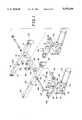
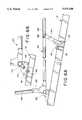
- FIG. 1is an exploded perspective view of a main support frame and a pair of power drive assemblies for a wheelchair according to the present invention
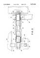
- FIG. 2is an enlarged cross-sectional view through a first end of a swing arm of one of the power drive assemblies of FIG. 1 when it is rotatably secured to the main support frame;
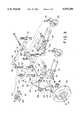
- FIG. 3is a reduced exploded perspective view of the frame, power drive assemblies and associated components of the wheelchair of FIG. 1;
- FIG. 4is an exploded perspective view of a seat frame secured to the wheelchair of FIG. 1;
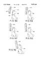
- FIGS. 5A-5Eare schematic views illustrating a back angle adjustment of the seatback of the wheelchair of FIG. 4.
- FIG. 6Ais an enlarged side elevational view of a portion of the main frame of the wheelchair of FIG. 1 to which the seat frame of FIG. 4 is secured;
- FIG. 6Bis an enlarged partially cross-sectional view of a portion of the main frame and seat frame of FIG. 6A;
- FIG. 7is an enlarged side elevational assembled view of the wheelchair of FIG. 1 showing a portion of the main frame and the power drive assembly secured thereto;
- FIG. 8is a perspective view of a wheelchair according to the present invention.
- FIG. 8is a perspective view of a wheelchair according to the present invention.
- FIG. 3which is an exploded perspective view of certain portions of the wheelchair of FIG. 8, illustrates the wheelchair's adjustable center of gravity and its independent suspension.
- FIG. 6Aillustrates the adjustable seat module of the wheelchair. While the invention is herein illustrated in connection with a powered wheelchair, it should be appreciated that certain of the features disclosed herein can also be used in manually propelled wheelchairs.
- the wheelchaircomprises an H-shaped wheelchair main support frame 10 having a first longitudinal side 12 with a front end 14, on which is provided a vertically extending socket 16, and a rear end 18.
- the framealso includes a second longitudinal side 20 having a front end 22, on which is provided a vertically extending socket 24, and a rear end 26. Connecting the first and second sides 12 and 20 is a bridge 28.
- the frameis preferably a hollow rectangular tube made of a conventional metal.
- the frameis of sufficient rigidity and thickness as to support a seat module, an occupant, as well as power drive assemblies and batteries. More specifically, secured to the frame 10 are first and second power drive assemblies.
- the first power drive assemblycomprises a first swing arm 30 and a first motor and gearbox assembly 32.
- the second power drive assemblycomprises a second swing arm 34 and a second motor and gearbox assembly 36. Since the two power drive assemblies are mirror images of each other, only the left power drive assembly illustrated in FIG. 1 will be discussed in detail in this specification, it being appreciated that the right power drive assembly is the mirror image of the left one.
- the first swing arm 30has on a first end thereof a cylindrical suspension arm 40.
- the suspension arm 40comprises a cylindrical outer sleeve 42.
- Located thereinare a pair of silent block rubber bushings 44 which are separated by a spacer 46.
- Each of the silent block rubber bushingscomprises an inner cylindrical sleeve 47 and an outer cylindrical sleeve 48, conventionally made of metal, which are separated by a sleeve 50 made of a suitable resilient material, such as rubber.
- the two resilient material sleeves 50damp vibrations of the power drive assembly transmitted by the outer sleeve 42 and reduce the amplitude thereof before such vibrations are transmitted to the main support frame 10.
- the spacer 46has a smaller external diameter than the internal diameter of the outer sleeve 42 to prevent the transmission of vibration between them.
- a support 52which can, if desired, comprise a pair of arms that define between them a slot as shown in FIG. 1.
- the support frame 10is a hollow box frame, thus the two second sides 12 and 20 are hollow.
- a bolt 54is inserted into the second side frame 20 through an aperture 55 (see FIG. 1) such that a head of the bolt 54 is located adjacent an inner side wall of the second side and a shaft of the bolt faces towards the center of the frame.
- the head of the boltis seated on a first tapered washer 56.
- a second tapered washer 56is located between the frame second side 20 and the adjacent silent block rubber bushing
- the shaft of the boltextends through the cylindrical suspension arm 40 and terminates on the far side of the support 52. There, it is secured to a shoulder nut 58 positioned between the arms of the support 52. In this way, the swing arm is fastened in a pivotal manner to the frame 10.
- a pair of apertures 59extend transversely through the two arms of the support 52 adjacent the free ends thereof.
- a fastener 60can be secured through these apertures in order to hold a front rail 62 of a battery support subframe 63 to the support 52 and hence to the frame 10.
- a cap 64is inserted into the aperture 55 in order to hide the head of the screw 54 and close the aperture 55 in the second side 20.
- the mirror image constructionis provided on the right side of the wheelchair, i.e. for the second power drive assembly.
- the first swing arm 30is also provided with a plate-like second end 66. Extending transversely through the second end are a plurality of spaced apertures 68. These are located in two sets of three along each side edge of the second end 68 (only the two sets of apertures along one side edge of the plate-like end 66 being visible in FIG. 1).
- the first power drive assemblyalso includes, as mentioned, a first motor and gearbox assembly 32.
- Thiscomprises a conventional motor 70 and a conventional gearbox 72 secured to one end of the motor. Extending normal to the gearbox is a drive shaft 74.
- a wedge 76is secured to the top face of the gearbox 72 by fasteners 77 extending through apertures 78 as best seen in FIG. 7.
- Extending through the wedge and into the top of the gearboxare four spaced apertures 79 which, as is evident from FIG. 1, are located approximately at the corners of the wedge. These apertures 79 can be aligned with one of the three sets of apertures 68 provided on the swing arm second end plate 66.
- first motor and gearbox assembly 32can be moved longitudinally in relationship to the first swing arm 30 by approximately two inches (5.08 cm.). Obviously, different distances can be chosen between the apertures and a larger number of apertures can be used to provide other ranges of adjustability.
- the motor and gear box assemblies 32 and 36are adjustably and removably mounted on the first and second swing arms 30 and 34.
- the motors 70malfunctions, it can be easily replaced without disassembling the entire wheelchair, or even an integral power module of such chair. In fact, only the defective motor and gear box assembly need be replaced in a simple and speedy operation.
- the use of separate motors to power each of the driven wheels 94is also advantageous to allow short radius turns for the wheelchair.
- the wheelchairincludes a pair of front casters 90. Each of these is mounted in a caster fork 92 having a stem which extends up through a respective socket 16, 24 at the front end of the respective sides of the frame 10 and is mounted thereto via bearings to allow for a rotation of the caster forks, and hence the casters, as necessary.
- the wheelchairis also provided with a pair of powered or driven wheels 94, only one of which is illustrated for simplicity.
- the wheel 94is secured to a wheel hub 96 which, in turn, is secured to the drive shaft 74 of the first motor and gearbox assembly 32.
- the pair of wedges 76 positioned atop the gearboxes 72enable a movement or shifting of the motor and gearbox assemblies 32 and 36 longitudinally forward and rearward in relation to the first and second swing arms 30, 32 while at the same time maintaining the chair at the same height.
- a seat module of the wheelchairdoes not increase or decrease its distance from a subjacent support surface.
- the bearings of the caster forks 92remain in a vertical position for a free and proper rotation of the caster forks and the casters mounted thereon.
- the anti-tip assembly 100includes first and second shock mount plates 102 and 104 which are substantially triangular in shape. Each of these includes a first aperture 106, located at an apex thereof, which can be aligned with a socket 108 provided on a rear end of the plate-like second end 62 of the first swing arm 30.
- a fastener 110such as a screw, can extend therethrough to secure the plates 102, 104 to the first swing arm 30.
- a tip of the screw 110is fastened in a nut 112 in order to hold the two plates 102, 104 on either side of the first swing arm 30.
- Each plateis also provided with a number of second apertures 114 located on a lower right hand corner of the plate. These apertures have the same spacing as the apertures 68 in the plate-like second end 66. Thus, three such apertures are provided and these are spaced longitudinally apart by approximately one inch (2.54 cm.). Any of the sets of such apertures can be aligned with a socket 115 extending from a rear face of the gearbox 72. When so aligned, a fastener 110 can extend therethrough and a nut 112 serves to secure these elements together.
- Each platealso includes a third aperture 116 on a lower left hand corner thereof. Supported between the two plates 102 and 104 and aligned with the third aperture 116, is an anti-tip wheel 118. A fastener 110 extends through the anti-tip wheel as well as a pair of spacers 120 located on either side of the anti-tip wheel in order to secure the wheel between the pair of plates.
- Each of the pair of platesalso includes a fourth aperture 122.
- These apertures 122can be aligned with a socket 124 located adjacent a bottom end of a shock absorber 126.
- One of the fasteners 110can, in this manner, secure the shock absorber bottom end between the two plates.
- the shock absorber 126is provided with a tension spring 127 for urging a piston rod of the shock absorber out of its casing.
- the shock absorber 126also includes a socket 128 located adjacent its top end.
- the socketcan be aligned with an aperture 132 adjacent the rear end 18 and 26 of a respective one of the frame first and second sides 12 and 20.
- the battery support frameis secured to the wheelchair frame 10, when its aperture 134 is aligned with the socket top end 128 and the frame aperture 132, by a suitable fastener 138.
- shock absorber 126is illustrated as being provided with a tension spring 127, it should be appreciated that the resilient biasing means illustrated can be replaced with a simple high spring rate type of spring (not illustrated). For example, rather than employing a 75 lb. per inch (517.1 kPa) spring 127 with the damping provided by the shock absorber, a 175 lb. per inch (1206.6 kPa) spring can be provided instead and no shock absorber employed.
- the systemincludes the pair of silent block rubber bushings 44 illustrated in FIG. 2.
- resilient material grommets and bushingsare provided at the shock absorber top mounting socket 128 and bottom mounting socket 124 as is known in the art.
- Movement of the first and second motor and gearbox assemblies 32 and 36 in relation to the first and second swing arms 30 and 34also necessitates a change in the aperture 114 which is aligned with the socket 115 at the rear of the motor and gearbox assembly 72 in order to align these elements together.
- the forwardmost aperture 68is employed as illustrated in FIG. 3 of the drawings, then the forwardmost aperture 114 needs to be employed on the pair of shock mount plates 102, 104.
- the rearwardmost aperture 68is employed, then the rearwardmost aperture 114 on the two plates needs to be aligned with the socket 115.
- a seat frame 150can be secured to the wheelchair frame 10.
- a pair of front seat bottom brackets 152which are secured by suitable fasteners 154 (see FIG. 6A) via aligned apertures located on the top and front surfaces of the bridge and a substantially horizontally oriented tab portion and a vertically oriented central portion of each front seat bracket (only the top fastener 154 is illustrated for the sake of simplicity).
- a pair of rear seat support brackets 160which are secured via fasteners 161 (see FIG. 6A) extending through an aligned aperture 162 on the base of each rear bracket (see FIG. 6B) such that the fasteners extend into either of a pair of apertures 163 (see FIG.
- the seat frame 150can be made in a variety of depths such that its side rails have different lengths. To this end, the seat frame can be made 14, 16, 18 or 20 inches deep (35.6, 40.6, 45.7 and 50.8 cm.) depending on the height of the occupant of the chair.
- a pair of front links 164which are secured by suitable fasteners 166 to a front rail 168 of the seat frame, as shown in FIG. 6A.
- the base portions of the front linkscan be secured at a desired height by fasteners 170 which extend through one of the pairs of aligned apertures 172 in the front brackets 152.
- four such pairs of aperturesare provided. This enables a tilting of the seat portion of the seat module from 80 degrees to 100 degrees in relation to a vertical plane, as desired.
- rear rail 174 of the seat frame 150is mounted on the support bracket 160.
- the seat frameincludes adjacent each rear corner a seat clamp bracket 176 welded to the rear rail 174. This is secured via suitable fasteners 178 to the rear support bracket 160.
- a substantially L-shaped angle plate 180having two spaced sets of apertures 182 and 184 in its upturned leg. Each of these include three apertures which are triangularly arranged.
- a back cane 190 of the seat modulecan be secured in varying orientations from 80 degrees to 100 degrees to a horizontal plane by employing different ones of the apertures 192 in the back cane 190 and sets of apertures 182 and 184 in the L-shaped angle plate 180 through which fasteners, (not shown) can extend, as is illustrated in FIGS. 5A-5E. In this way, the seat assembly can be configured to meet the needs of the user of the wheelchair.
- the wheelchairincludes the main frame 10 as well as the first and second power drive assemblies. In that connection, visible is the first motor and gear box assembly 32 and the second motor and gear box assembly 36.
- Mounted on the seat frame 150is a seat 200 and a seatback 202.
- first and second arm rests 204 and 206are mounted on the seat frame. In this connection, each of these arm rests is seated in a front socket 208 and a rear socket 210 (see FIG. 4) provided along each of the side edges of the seat frame 150.
- the seat frameis further provided with a pair of leg rest sockets 214 into which leg rests (not illustrated) can be secured as desired.
- a control panel 220is mounted on the seat frame so as to enable the occupant of the wheelchair to direct the movement thereof.
- the control panelcan include a joystick-type control, as well as one or more switches to direct the operation of the chair.
- at least one battery 222is provided in order to power the motors of the wheelchair. This is mounted on the battery subframe 63 (see FIG. 3) which is secured to the main frame 10.
- the powered chair of the present inventioncan be provided in two weight classes.
- a standard weight class wheelchair employing a larger diameter, thinner tire 94can be used for occupants up to 250 lbs. (113.5 Kg.)
- a heavier duty wheelchair usable by occupants up to 400 lbs. (181.4 Kg.)can be provided with a smaller diameter, thicker or wider, tire 94.
- the smaller tiregives an increased effective gear ratio so that the same motor has a greater pulling capacity as needed for the heavier load.
- motors 70are angled upwardly, i.e. away from the subjacent support surface, in order to provide for good curb clearance for the wheelchair.
- the adjustability of the first and second motor and gear box assemblies 32 and 36 on the first and second swing arms 30 and 34, respectively,enables a change in the moment of inertia of the wheelchair about a vertical axis. This facilitates the ability of the occupant of the wheelchair to turn the wheelchair. Such a configuration is especially beneficial in facilitating short radius turns. In addition, this configuration enables a more controlled turn acceleration, thereby facilitating user maneuverability in confined areas.
Landscapes
- Health & Medical Sciences (AREA)
- Life Sciences & Earth Sciences (AREA)
- Animal Behavior & Ethology (AREA)
- General Health & Medical Sciences (AREA)
- Public Health (AREA)
- Veterinary Medicine (AREA)
- Handcart (AREA)
Abstract
Description
Claims (22)
Priority Applications (4)
| Application Number | Priority Date | Filing Date | Title |
|---|---|---|---|
| US08/228,584US5575348A (en) | 1994-04-15 | 1994-04-15 | Powered wheelchair with adjustable center of gravity and independent suspension |
| EP95301059AEP0677285B1 (en) | 1994-04-15 | 1995-02-20 | Powered wheelchair with adjustable center of gravity and independent suspension |
| DE69516750TDE69516750T2 (en) | 1994-04-15 | 1995-02-20 | Self-propelled wheelchair with adjustable center of gravity and independent suspension |
| US08/694,484US5853059A (en) | 1994-04-15 | 1996-08-07 | Powered wheelchair with adjustable center of gravity and independent suspension |
Applications Claiming Priority (1)
| Application Number | Priority Date | Filing Date | Title |
|---|---|---|---|
| US08/228,584US5575348A (en) | 1994-04-15 | 1994-04-15 | Powered wheelchair with adjustable center of gravity and independent suspension |
Related Child Applications (1)
| Application Number | Title | Priority Date | Filing Date |
|---|---|---|---|
| US08/694,484ContinuationUS5853059A (en) | 1994-04-15 | 1996-08-07 | Powered wheelchair with adjustable center of gravity and independent suspension |
Publications (1)
| Publication Number | Publication Date |
|---|---|
| US5575348Atrue US5575348A (en) | 1996-11-19 |
Family
ID=22857768
Family Applications (2)
| Application Number | Title | Priority Date | Filing Date |
|---|---|---|---|
| US08/228,584Expired - Fee RelatedUS5575348A (en) | 1994-04-15 | 1994-04-15 | Powered wheelchair with adjustable center of gravity and independent suspension |
| US08/694,484Expired - Fee RelatedUS5853059A (en) | 1994-04-15 | 1996-08-07 | Powered wheelchair with adjustable center of gravity and independent suspension |
Family Applications After (1)
| Application Number | Title | Priority Date | Filing Date |
|---|---|---|---|
| US08/694,484Expired - Fee RelatedUS5853059A (en) | 1994-04-15 | 1996-08-07 | Powered wheelchair with adjustable center of gravity and independent suspension |
Country Status (3)
| Country | Link |
|---|---|
| US (2) | US5575348A (en) |
| EP (1) | EP0677285B1 (en) |
| DE (1) | DE69516750T2 (en) |
Cited By (73)
| Publication number | Priority date | Publication date | Assignee | Title |
|---|---|---|---|---|
| US5718442A (en)* | 1995-12-27 | 1998-02-17 | Mechanical Application Designs, Inc. | Power wheelchair with extended power seat frame tilt |
| US5853059A (en)* | 1994-04-15 | 1998-12-29 | Invacare Corporation | Powered wheelchair with adjustable center of gravity and independent suspension |
| EP0908167A2 (en) | 1997-10-06 | 1999-04-14 | Invacare Corporation | Reversible seat for front wheel drive and rear wheel drive power wheelchair having stepless angular adjustment |
| EP0908166A2 (en) | 1997-10-06 | 1999-04-14 | Invacare Corporation | Anti-tip assembly for power wheelchair |
| EP0908165A2 (en) | 1997-10-06 | 1999-04-14 | Invacare Corporation | Adjustable front wheel stabilizer for power wheelchair |
| US5944131A (en)* | 1996-07-03 | 1999-08-31 | Pride Health Care, Inc. | Mid-wheel drive power wheelchair |
| USD413554S (en) | 1998-09-28 | 1999-09-07 | Kurt Manufacturing Company | Powered wheelchair |
| WO2000009356A1 (en)* | 1998-08-14 | 2000-02-24 | Sunrise Medical Hhg Inc. | Suspension system for a wheelchair |
| US6032976A (en)* | 1997-09-08 | 2000-03-07 | Sunrise Medical Hhg Inc. | Wheelchair with tilting seat |
| US6129165A (en) | 1996-07-03 | 2000-10-10 | Pride Mobility Products, Corporation | Curb-climbing power wheelchair |
| US6176335B1 (en) | 1996-07-03 | 2001-01-23 | Pride Mobility Products, Corporation | Power wheelchair |
| WO2001008623A1 (en) | 1999-07-30 | 2001-02-08 | Invacare Corporation | Wheelchair stabilizing assembly |
| US6186252B1 (en) | 1996-07-03 | 2001-02-13 | Pride Mobility Products, Corporation | Foldable midwheel drive power chair |
| US6250661B1 (en)* | 1998-11-13 | 2001-06-26 | Sunrise Medical Hhg Inc. | Tilt system for a powered wheelchair seat |
| US6279927B1 (en)* | 1997-06-06 | 2001-08-28 | Misawahomu Kabushiki Kaisha | Wheelchair |
| US6341657B1 (en) | 1998-11-18 | 2002-01-29 | Electric Mobility Corporation | Suspension for central drive vehicle |
| US6357793B1 (en)* | 1999-10-29 | 2002-03-19 | Sunrise Medical Hhg Inc. | Anti-tip wheel |
| US6375209B1 (en) | 1997-10-06 | 2002-04-23 | Kurt Manufacturing Company | Powered wheelchair |
| US6443252B1 (en) | 1999-08-13 | 2002-09-03 | Royce C. Andes | Passenger standing platform on a powered wheelchair |
| US6533306B2 (en) | 2001-01-18 | 2003-03-18 | Pride Mobility Products Corporation | Adjustable height anti-tip wheels for a power wheelchair |
| US6611975B1 (en)* | 2001-02-23 | 2003-09-02 | Roy D. Ricketts | Motorized bed assembly |
| US20030168265A1 (en)* | 2000-10-27 | 2003-09-11 | Gerold Goertzen | Obstacle traversing wheelchair |
| US20030205878A1 (en)* | 2002-05-01 | 2003-11-06 | Martis Charles J. | Suspension system for a wheelchair |
| US20040004342A1 (en)* | 2002-04-30 | 2004-01-08 | Mulhern James P. | Rear wheel drive power wheelchair with ground-contacting anti-tip wheels |
| US20040032119A1 (en)* | 2002-05-29 | 2004-02-19 | Sy Tran | Control of an anti-tip wheel in wheelchairs |
| US20040046358A1 (en)* | 2002-09-09 | 2004-03-11 | White Gerald J. | Stabilizing system for a reclinable wheelchair |
| US20040060748A1 (en)* | 2001-10-10 | 2004-04-01 | Molnar James H. | Wheelchair suspension |
| US20040094944A1 (en)* | 2002-08-16 | 2004-05-20 | Gerald Goertzen | Vehicle having an anti-dive/lockout mechanism |
| US20040150204A1 (en)* | 2002-10-25 | 2004-08-05 | Gerald Goertzen | Suspension with releasable locking system |
| US20050000742A1 (en)* | 2003-07-02 | 2005-01-06 | Mulhern James P. | Rear wheel drive power wheelchair |
| US20050088024A1 (en)* | 2003-10-08 | 2005-04-28 | Rozaieski Michael J. | Reclining seat with movable back support |
| US20050127631A1 (en)* | 2003-12-15 | 2005-06-16 | Schaffner Walter E. | Curb-climbing power wheelchair |
| US20050151360A1 (en)* | 2003-08-18 | 2005-07-14 | Invacare Corporation | Self-stabilizing suspension for wheeled vehicles |
| US6923278B2 (en) | 2002-05-06 | 2005-08-02 | Pride Mobility Products Corporation | Adjustable anti-tip wheels for power wheelchair |
| US6938923B2 (en) | 2002-04-30 | 2005-09-06 | Pride Mobility Products Corporation | Power wheelchair |
| US20050279540A1 (en)* | 2004-06-07 | 2005-12-22 | Wisner Donald W | Adjustable wheelchair |
| US20060087097A1 (en)* | 2004-08-16 | 2006-04-27 | Kramer Kenneth L | Home care equipment system |
| US20060097478A1 (en)* | 2004-11-09 | 2006-05-11 | Invacare Corporation | Anti-tip wheelchair |
| US20060097475A1 (en)* | 2004-10-22 | 2006-05-11 | Frederick Kiwak | Personal mobility vehicle suspension system having a compensation mechanism |
| US7066290B2 (en) | 2001-10-19 | 2006-06-27 | Invacare Corp. | Wheelchair suspension having pivotal motor mount |
| US20070039765A1 (en)* | 2005-08-22 | 2007-02-22 | Mei-Ying Lin | Controlling method for breaking automatically having safety suspense for electrical wheel chair |
| US20070039766A1 (en)* | 2005-08-18 | 2007-02-22 | Jackson Mark A | Midwheel drive wheelchair with independent front and rear suspension |
| WO2007049301A2 (en) | 2006-10-23 | 2007-05-03 | Multivac India Private Limited | Single arm control wheelchair |
| US20070145711A1 (en)* | 2002-04-30 | 2007-06-28 | Mulhern James P | Rear wheel drive vehicle with ground-contacting anti-tip wheels |
| US20080066974A1 (en)* | 2006-09-14 | 2008-03-20 | Pearlman Jonathan L | Personal vehicle |
| US20080157501A1 (en)* | 2004-10-29 | 2008-07-03 | Flemming Moller | Comfort Wheelchair |
| US20080231006A1 (en)* | 2003-09-26 | 2008-09-25 | Adriaan Van Eeden | Inter-Convertible Single Person Type Transporting Aid |
| US20100038880A1 (en)* | 2008-08-15 | 2010-02-18 | Bagg Christian Peter Edward | Modular and/or configurable wheelchair apparatus |
| US20110083915A1 (en)* | 2009-10-13 | 2011-04-14 | Criterion Health, Inc. | Adjustable mid-wheel power wheelchair drive system |
| US20110083913A1 (en)* | 2009-10-09 | 2011-04-14 | Invacare Corporation | Wheelchair suspension |
| US8272461B2 (en) | 2007-02-08 | 2012-09-25 | Invacare Corporation | Wheelchair suspension |
| US8297388B2 (en) | 2007-01-12 | 2012-10-30 | Invacare International Sarl | Wheelchair with suspension arms |
| US8807251B2 (en) | 2010-06-15 | 2014-08-19 | Invacare Corporation | Electric motor and brake assembly |
| US8851214B2 (en) | 2010-07-15 | 2014-10-07 | Permobil Ab | Electric mid-wheel drive wheelchair |
| US8910975B2 (en) | 2007-02-14 | 2014-12-16 | Invacare Corporation | Wheelchair with suspension |
| US9308143B2 (en) | 2012-02-15 | 2016-04-12 | Invacare Corporation | Wheelchair suspension |
| US9532912B2 (en) | 2010-03-16 | 2017-01-03 | Invacare Corporation | Wheelchair seat assembly |
| US20190083336A1 (en)* | 2017-09-15 | 2019-03-21 | Deka Products Limited Partnership | Mobility Device Seat |
| US10377403B2 (en) | 2015-11-06 | 2019-08-13 | Caster Concepts, Inc. | Powered utility cart and compliant drive wheel therefor |
| US20190307620A1 (en)* | 2016-09-23 | 2019-10-10 | Otto Bock Mobility Solutions Gmbh | Chassis for a mobility aid and for an electric wheelchair |
| US20200107979A1 (en)* | 2018-10-03 | 2020-04-09 | Earthwatch, L. L. C. | Suspension systems, powered wheelchairs with independent suspension systems, and method for assembling such powered wheelchairs |
| US10926756B2 (en) | 2016-02-23 | 2021-02-23 | Deka Products Limited Partnership | Mobility device |
| US11096846B2 (en)* | 2018-02-14 | 2021-08-24 | Batec Mobility, S.L. | Auxiliary frame systems for wheelchairs |
| US11213441B2 (en) | 2002-10-25 | 2022-01-04 | Invacare Corporation | Suspension for wheeled vehicles |
| US11388859B2 (en)* | 2019-01-03 | 2022-07-19 | Ls Mtron Ltd. | Auxiliary wheel for lawn mower |
| US11399995B2 (en) | 2016-02-23 | 2022-08-02 | Deka Products Limited Partnership | Mobility device |
| US11681293B2 (en) | 2018-06-07 | 2023-06-20 | Deka Products Limited Partnership | System and method for distributed utility service execution |
| US11679044B2 (en) | 2016-02-23 | 2023-06-20 | Deka Products Limited Partnership | Mobility device |
| US11903887B2 (en) | 2020-02-25 | 2024-02-20 | Invacare Corporation | Wheelchair and suspension systems |
| US11957631B2 (en) | 2022-07-13 | 2024-04-16 | Invacare Corporation | Wheelchair and suspension systems |
| CN118557372A (en)* | 2024-06-21 | 2024-08-30 | 江苏省镇江第一中学 | Intelligent control obstacle crossing wheelchair and obstacle crossing method |
| USD1047785S1 (en) | 2017-05-20 | 2024-10-22 | Deka Products Limited Partnership | Toggle control device |
| US12440401B2 (en) | 2024-05-22 | 2025-10-14 | Deka Products Limited Partnership | Mobility device |
Families Citing this family (26)
| Publication number | Priority date | Publication date | Assignee | Title |
|---|---|---|---|---|
| US5772237A (en)* | 1996-05-21 | 1998-06-30 | Teftec Corporation | Suspension system for powered wheelchair |
| US6139037A (en) | 1996-07-23 | 2000-10-31 | Papac; James B. | Wheelchair |
| US6886843B1 (en)* | 1996-07-23 | 2005-05-03 | Plain Sense Wheelchairs, Inc. | Seating frame for wheelchair |
| US6276474B1 (en)* | 1997-02-18 | 2001-08-21 | Rockwell Heavy Vehicle Systems, Inc. | Low floor drive unit assembly for an electrically driven vehicle |
| FR2763840B1 (en)* | 1997-05-30 | 1999-10-29 | Yves Dignat | WHEELCHAIR WITH IMPROVED SUSPENSION |
| DE29718533U1 (en)* | 1997-10-18 | 1998-02-12 | Sopur Medizintechnik GmbH, 69254 Malsch | Electric wheelchair |
| US6179076B1 (en)* | 1998-10-06 | 2001-01-30 | Sunnybrook & Women's College Health Sciences Centre | Motorized chair base |
| US6405816B1 (en)* | 1999-06-03 | 2002-06-18 | Deka Products Limited Partnership | Mechanical improvements to a personal vehicle |
| US6352273B1 (en)* | 1999-10-29 | 2002-03-05 | Sunrise Medical Hhg Inc. | Seat mounting assembly |
| US6390554B1 (en) | 1999-11-23 | 2002-05-21 | 1239907 Ontario Limited | Weight positioning reclining seat kit for wheelchairs |
| DE20121824U1 (en)* | 2001-07-26 | 2003-06-18 | Ulrich Alber GmbH & Co. KG, 72461 Albstadt | Electric wheelchair with modular construction has chassis fitted with steered and driven wheels and supporting seat and electric storage batteries |
| US20040084230A1 (en)* | 2002-10-28 | 2004-05-06 | Christopher Grymko | Transportable wheelchair |
| DE10300946B3 (en)* | 2003-01-13 | 2004-08-26 | Meyra Wilhelm Meyer Gmbh & Co Kg | Power Wheelchair |
| CA2471915C (en)* | 2003-06-23 | 2009-08-04 | Allseating Corporation | Adjustable grommet for a chair seat |
| TWM244070U (en)* | 2003-08-13 | 2004-09-21 | Pihsiang Machinery Mfg Co Ltd | Suspending structure for a wheelchair |
| US7207403B2 (en)* | 2003-10-08 | 2007-04-24 | Pride Mobility Products Corporation | Transportable power wheelchair |
| JP2006056354A (en)* | 2004-08-19 | 2006-03-02 | Honda Motor Co Ltd | High voltage wiring protection structure for electric vehicles |
| US7314105B2 (en)* | 2004-09-16 | 2008-01-01 | Arvinmeritor Technology, Llc | Electric drive axle assembly with independent dual motors |
| NZ540127A (en)* | 2005-05-18 | 2008-03-28 | Metalform Dannevirke Ltd | Wheel chair with seat lowerable to floor level, and able to raise to high level, with enhanced stability and centre of gravity location |
| US7819415B2 (en)* | 2006-06-06 | 2010-10-26 | University Of South Florida | Lateral wheelchair movement mechanism |
| DE102009051118B4 (en)* | 2009-10-13 | 2014-04-30 | Otto Bock Mobility Solutions Gmbh | electric wheelchair |
| US20130197732A1 (en) | 2012-01-26 | 2013-08-01 | Jonathan L. Pearlman | Active stability devices and systems for mobile devices |
| CN104323895B (en)* | 2014-10-25 | 2017-02-15 | 管中林 | Wheelchair capable of climbing stairs and running on field |
| CN105250088B (en)* | 2015-11-17 | 2017-05-31 | 南京康尼机电股份有限公司 | A kind of Intelligent seat |
| US11259974B1 (en) | 2016-02-25 | 2022-03-01 | Ki Mobility Llc | Dampening system for wheelchair and wheelchair therewith |
| IT202200013033A1 (en)* | 2022-06-20 | 2023-12-20 | Spencer Italia Soc A Responsabilita Limitata A Socio Unico | SEDAN CHAIRS AND STAIRCASES WITH SHOCK ABSORBER DEVICE |
Citations (37)
| Publication number | Priority date | Publication date | Assignee | Title |
|---|---|---|---|---|
| US1973627A (en)* | 1933-03-10 | 1934-09-11 | Evan C Harter | Chair |
| US3881773A (en)* | 1974-06-03 | 1975-05-06 | Everest & Jennings | Reclining back wheelchair |
| US3893529A (en)* | 1974-04-22 | 1975-07-08 | Jr Andrew Karchak | Wheelchair drive package |
| US3901337A (en)* | 1971-11-24 | 1975-08-26 | Spastics Soc | Wheel chairs |
| US3917312A (en)* | 1974-07-29 | 1975-11-04 | Everst & Jennings Inc | Indoor/outdoor wheelchair frame |
| US4078817A (en)* | 1976-06-10 | 1978-03-14 | Reme Enterprises, Inc. | Shock absorber attachment for wheelchairs or the like |
| GB2040237A (en)* | 1978-11-16 | 1980-08-28 | Bergman P G | Dismountable wheel-chair |
| GB2061197A (en)* | 1979-10-04 | 1981-05-13 | New Zealand Dev Finance | Modular wheel chair |
| US4310167A (en)* | 1980-05-15 | 1982-01-12 | The University Of Virginia Alumni Patents Foundation | Center of gravity wheelchair with articulated chassis |
| US4405142A (en)* | 1981-03-09 | 1983-09-20 | Stainless Medical Products, Inc. | Knock down wheel chair |
| US4436320A (en)* | 1981-03-25 | 1984-03-13 | Everest & Jennings, Inc. | Chassis for invalid wheelchairs |
| US4455031A (en)* | 1981-11-27 | 1984-06-19 | Hosaka Wayne N | Wheelchair |
| GB2141980A (en)* | 1983-06-23 | 1985-01-09 | Tuenkers Maschinenbau Gmbh | Adjustable wheelchair |
| US4500102A (en)* | 1982-11-16 | 1985-02-19 | Invacare Corporation | Sports wheelchair |
| US4641848A (en)* | 1985-04-15 | 1987-02-10 | Ayers Robert C | Wheelchair with rocking seat assembly |
| US4730842A (en)* | 1986-04-18 | 1988-03-15 | Wheel Ring, Inc. | Adjustable wheelchair |
| EP0268960A2 (en)* | 1986-11-28 | 1988-06-01 | MEYRA WILHELM MEYER GmbH & Co KG | Wheel chair for the sick |
| US4805925A (en)* | 1982-11-16 | 1989-02-21 | Invacare Corporation | Adjustable rear wheel mounting assembly for wheelchairs |
| US4861056A (en)* | 1987-11-12 | 1989-08-29 | Iron Horse Productions, Inc. | Folding wheelchair with improved frame and suspension system |
| EP0339500A2 (en)* | 1988-04-28 | 1989-11-02 | Günter Meier GmbH | Wheel chair |
| WO1990005515A1 (en)* | 1988-11-16 | 1990-05-31 | Sunrise Medical Ltd | Vehicle |
| US4967864A (en)* | 1988-10-05 | 1990-11-06 | Everest & Jennings, Inc. | Modular power drive wheelchair |
| US4989890A (en)* | 1986-09-30 | 1991-02-05 | Invacare Corporation | Length and width adjustable wheelchair |
| US5020816A (en)* | 1987-10-19 | 1991-06-04 | Mulholland Designs, Inc. | Adjustable frame wheelchair |
| US5044647A (en)* | 1989-11-17 | 1991-09-03 | Folio Products, Inc. | Stabilized reclining wheelchair seat |
| US5076602A (en)* | 1990-04-27 | 1991-12-31 | Medical Composite Technology | Seating system for a wheel chair |
| US5113959A (en)* | 1989-09-10 | 1992-05-19 | Propel Partnership 1987 | Electric drive attachment for a wheelchair |
| US5125468A (en)* | 1989-06-02 | 1992-06-30 | Coker Theodore R | Electric control for wheelchair drive unit |
| US5156226A (en)* | 1988-10-05 | 1992-10-20 | Everest & Jennings, Inc. | Modular power drive wheelchair |
| EP0511113A2 (en)* | 1991-04-26 | 1992-10-28 | Etablissements POIRIER Société anonyme | Personal vehicle usable in a handpropelled or motorised mode, especially a wheelchair or tricycle |
| US5176393A (en)* | 1990-04-27 | 1993-01-05 | Medical Composite Technology | Modular wheelchair |
| US5180025A (en)* | 1991-12-13 | 1993-01-19 | Yeh Bean Shung | Wheeled-chair chassis with a suspension mechanism |
| US5197559A (en)* | 1990-09-04 | 1993-03-30 | Fortress Life-Style, Inc. | Foldable wheelchair with optional power or manual drive |
| WO1993024342A1 (en)* | 1992-06-02 | 1993-12-09 | Quickie Designs Inc. | Powered wheelchair with a detachable power drive assembly |
| US5294141A (en)* | 1990-11-14 | 1994-03-15 | Invacare Corporation | Attended to self propelled convertible pivoting wheelchair |
| US5297021A (en)* | 1992-11-16 | 1994-03-22 | Koerlin James M | Zero shear recliner/tilt wheelchair seat |
| US5366037A (en)* | 1992-11-23 | 1994-11-22 | Invacare Corporation | Powered wheelchair having drive motors integrated into driven wheels |
Family Cites Families (12)
| Publication number | Priority date | Publication date | Assignee | Title |
|---|---|---|---|---|
| GB1463500A (en)* | 1973-06-09 | 1977-02-02 | Cragg H | Wheelchairs |
| FR2455886A1 (en)* | 1979-05-11 | 1980-12-05 | Freon Jean Francois | Electrically propelled wheelchair for handicapped person - has collapsible seat mounted on cantilever chassis with independent drive motors powering rear wheels |
| US4387325A (en)* | 1981-04-15 | 1983-06-07 | Invacare Corporation | Electric wheelchair with speed control circuit |
| US4655471A (en)* | 1986-01-13 | 1987-04-07 | Peek Gregory A | Wheelchair having adjustable backrest |
| DE3879864T2 (en)* | 1987-10-19 | 1993-08-26 | Mulholland Designs Inc | ADJUSTABLE WHEELCHAIR FRAME. |
| JPH0790825B2 (en)* | 1988-06-11 | 1995-10-04 | 株式会社クボタ | Small electric car |
| GB2224980B (en)* | 1988-11-08 | 1992-09-09 | Peter James Rae Bradshaw | A wheelchair |
| US5209509A (en)* | 1990-05-26 | 1993-05-11 | Gunnell, Inc. | Wheelchair footrest assembly |
| US5076390A (en)* | 1990-07-03 | 1991-12-31 | Haskins John T | Multiple mode wheelchair construction |
| US5203610A (en)* | 1990-11-14 | 1993-04-20 | Invacare Corporation | Reclining lift chair having wheels for transport |
| NL9202183A (en)* | 1992-12-17 | 1994-07-18 | Seenus Nl Bv R Van | Wheelchair. |
| US5575348A (en)* | 1994-04-15 | 1996-11-19 | Invacare Corporation | Powered wheelchair with adjustable center of gravity and independent suspension |
- 1994
- 1994-04-15USUS08/228,584patent/US5575348A/ennot_activeExpired - Fee Related
- 1995
- 1995-02-20EPEP95301059Apatent/EP0677285B1/ennot_activeExpired - Lifetime
- 1995-02-20DEDE69516750Tpatent/DE69516750T2/ennot_activeExpired - Fee Related
- 1996
- 1996-08-07USUS08/694,484patent/US5853059A/ennot_activeExpired - Fee Related
Patent Citations (38)
| Publication number | Priority date | Publication date | Assignee | Title |
|---|---|---|---|---|
| US1973627A (en)* | 1933-03-10 | 1934-09-11 | Evan C Harter | Chair |
| US3901337A (en)* | 1971-11-24 | 1975-08-26 | Spastics Soc | Wheel chairs |
| US3893529A (en)* | 1974-04-22 | 1975-07-08 | Jr Andrew Karchak | Wheelchair drive package |
| US3881773A (en)* | 1974-06-03 | 1975-05-06 | Everest & Jennings | Reclining back wheelchair |
| US3917312A (en)* | 1974-07-29 | 1975-11-04 | Everst & Jennings Inc | Indoor/outdoor wheelchair frame |
| US4078817A (en)* | 1976-06-10 | 1978-03-14 | Reme Enterprises, Inc. | Shock absorber attachment for wheelchairs or the like |
| GB2040237A (en)* | 1978-11-16 | 1980-08-28 | Bergman P G | Dismountable wheel-chair |
| GB2061197A (en)* | 1979-10-04 | 1981-05-13 | New Zealand Dev Finance | Modular wheel chair |
| US4310167A (en)* | 1980-05-15 | 1982-01-12 | The University Of Virginia Alumni Patents Foundation | Center of gravity wheelchair with articulated chassis |
| US4405142A (en)* | 1981-03-09 | 1983-09-20 | Stainless Medical Products, Inc. | Knock down wheel chair |
| US4436320A (en)* | 1981-03-25 | 1984-03-13 | Everest & Jennings, Inc. | Chassis for invalid wheelchairs |
| US4455031A (en)* | 1981-11-27 | 1984-06-19 | Hosaka Wayne N | Wheelchair |
| US4500102A (en)* | 1982-11-16 | 1985-02-19 | Invacare Corporation | Sports wheelchair |
| US4805925A (en)* | 1982-11-16 | 1989-02-21 | Invacare Corporation | Adjustable rear wheel mounting assembly for wheelchairs |
| GB2141980A (en)* | 1983-06-23 | 1985-01-09 | Tuenkers Maschinenbau Gmbh | Adjustable wheelchair |
| US4641848A (en)* | 1985-04-15 | 1987-02-10 | Ayers Robert C | Wheelchair with rocking seat assembly |
| US4730842A (en)* | 1986-04-18 | 1988-03-15 | Wheel Ring, Inc. | Adjustable wheelchair |
| US4989890A (en)* | 1986-09-30 | 1991-02-05 | Invacare Corporation | Length and width adjustable wheelchair |
| EP0268960A2 (en)* | 1986-11-28 | 1988-06-01 | MEYRA WILHELM MEYER GmbH & Co KG | Wheel chair for the sick |
| US5020816A (en)* | 1987-10-19 | 1991-06-04 | Mulholland Designs, Inc. | Adjustable frame wheelchair |
| US4861056A (en)* | 1987-11-12 | 1989-08-29 | Iron Horse Productions, Inc. | Folding wheelchair with improved frame and suspension system |
| EP0339500A2 (en)* | 1988-04-28 | 1989-11-02 | Günter Meier GmbH | Wheel chair |
| US5156226A (en)* | 1988-10-05 | 1992-10-20 | Everest & Jennings, Inc. | Modular power drive wheelchair |
| US4967864A (en)* | 1988-10-05 | 1990-11-06 | Everest & Jennings, Inc. | Modular power drive wheelchair |
| WO1990005515A1 (en)* | 1988-11-16 | 1990-05-31 | Sunrise Medical Ltd | Vehicle |
| US5125468A (en)* | 1989-06-02 | 1992-06-30 | Coker Theodore R | Electric control for wheelchair drive unit |
| US5113959A (en)* | 1989-09-10 | 1992-05-19 | Propel Partnership 1987 | Electric drive attachment for a wheelchair |
| US5044647A (en)* | 1989-11-17 | 1991-09-03 | Folio Products, Inc. | Stabilized reclining wheelchair seat |
| US5076602A (en)* | 1990-04-27 | 1991-12-31 | Medical Composite Technology | Seating system for a wheel chair |
| US5176393A (en)* | 1990-04-27 | 1993-01-05 | Medical Composite Technology | Modular wheelchair |
| US5197559A (en)* | 1990-09-04 | 1993-03-30 | Fortress Life-Style, Inc. | Foldable wheelchair with optional power or manual drive |
| US5294141A (en)* | 1990-11-14 | 1994-03-15 | Invacare Corporation | Attended to self propelled convertible pivoting wheelchair |
| EP0511113A2 (en)* | 1991-04-26 | 1992-10-28 | Etablissements POIRIER Société anonyme | Personal vehicle usable in a handpropelled or motorised mode, especially a wheelchair or tricycle |
| US5180025A (en)* | 1991-12-13 | 1993-01-19 | Yeh Bean Shung | Wheeled-chair chassis with a suspension mechanism |
| WO1993024342A1 (en)* | 1992-06-02 | 1993-12-09 | Quickie Designs Inc. | Powered wheelchair with a detachable power drive assembly |
| US5351774A (en)* | 1992-06-02 | 1994-10-04 | Quickie Designs Inc. | Powered wheelchair with a detachable power drive assembly |
| US5297021A (en)* | 1992-11-16 | 1994-03-22 | Koerlin James M | Zero shear recliner/tilt wheelchair seat |
| US5366037A (en)* | 1992-11-23 | 1994-11-22 | Invacare Corporation | Powered wheelchair having drive motors integrated into driven wheels |
Cited By (157)
| Publication number | Priority date | Publication date | Assignee | Title |
|---|---|---|---|---|
| US5853059A (en)* | 1994-04-15 | 1998-12-29 | Invacare Corporation | Powered wheelchair with adjustable center of gravity and independent suspension |
| US5718442A (en)* | 1995-12-27 | 1998-02-17 | Mechanical Application Designs, Inc. | Power wheelchair with extended power seat frame tilt |
| US6640916B2 (en) | 1996-07-03 | 2003-11-04 | Pride Mobility Products, Corporation | Mid-wheel drive power wheelchair |
| US6186252B1 (en) | 1996-07-03 | 2001-02-13 | Pride Mobility Products, Corporation | Foldable midwheel drive power chair |
| US6176335B1 (en) | 1996-07-03 | 2001-01-23 | Pride Mobility Products, Corporation | Power wheelchair |
| US5944131A (en)* | 1996-07-03 | 1999-08-31 | Pride Health Care, Inc. | Mid-wheel drive power wheelchair |
| US6129165A (en) | 1996-07-03 | 2000-10-10 | Pride Mobility Products, Corporation | Curb-climbing power wheelchair |
| US6199647B1 (en) | 1996-07-03 | 2001-03-13 | Pride Mobility Products Corporation | Mid-wheel drive power wheelchair |
| US6279927B1 (en)* | 1997-06-06 | 2001-08-28 | Misawahomu Kabushiki Kaisha | Wheelchair |
| US6032976A (en)* | 1997-09-08 | 2000-03-07 | Sunrise Medical Hhg Inc. | Wheelchair with tilting seat |
| EP0908165A3 (en)* | 1997-10-06 | 1999-12-08 | Invacare Corporation | Adjustable front wheel stabilizer for power wheelchair |
| EP0908166A3 (en)* | 1997-10-06 | 1999-12-08 | Invacare Corporation | Anti-tip assembly for power wheelchair |
| US6041876A (en)* | 1997-10-06 | 2000-03-28 | Invacare Corporation | Anti-tip assembly for power wheelchair |
| US6375209B1 (en) | 1997-10-06 | 2002-04-23 | Kurt Manufacturing Company | Powered wheelchair |
| EP0908167A3 (en)* | 1997-10-06 | 1999-12-08 | Invacare Corporation | Reversible seat for front wheel drive and rear wheel drive power wheelchair having stepless angular adjustment |
| US6131679A (en)* | 1997-10-06 | 2000-10-17 | Invacare Corporation | Anti-tip assembly for power wheelchair |
| EP0908165A2 (en) | 1997-10-06 | 1999-04-14 | Invacare Corporation | Adjustable front wheel stabilizer for power wheelchair |
| EP0908166A2 (en) | 1997-10-06 | 1999-04-14 | Invacare Corporation | Anti-tip assembly for power wheelchair |
| EP0908167A2 (en) | 1997-10-06 | 1999-04-14 | Invacare Corporation | Reversible seat for front wheel drive and rear wheel drive power wheelchair having stepless angular adjustment |
| US6234507B1 (en) | 1998-08-14 | 2001-05-22 | Sunrise Medical Hhg Inc. | Suspension system for a wheelchair |
| WO2000009356A1 (en)* | 1998-08-14 | 2000-02-24 | Sunrise Medical Hhg Inc. | Suspension system for a wheelchair |
| US6070898A (en)* | 1998-08-14 | 2000-06-06 | Sunrise Medical, Inc. | Suspension system for a wheelchair |
| USD413554S (en) | 1998-09-28 | 1999-09-07 | Kurt Manufacturing Company | Powered wheelchair |
| US6250661B1 (en)* | 1998-11-13 | 2001-06-26 | Sunrise Medical Hhg Inc. | Tilt system for a powered wheelchair seat |
| US6341657B1 (en) | 1998-11-18 | 2002-01-29 | Electric Mobility Corporation | Suspension for central drive vehicle |
| WO2001008623A1 (en) | 1999-07-30 | 2001-02-08 | Invacare Corporation | Wheelchair stabilizing assembly |
| US6443252B1 (en) | 1999-08-13 | 2002-09-03 | Royce C. Andes | Passenger standing platform on a powered wheelchair |
| US6357793B1 (en)* | 1999-10-29 | 2002-03-19 | Sunrise Medical Hhg Inc. | Anti-tip wheel |
| US20030168264A1 (en)* | 2000-10-27 | 2003-09-11 | Gerold Goertzen | Obstacle traversing wheelchair |
| US20030168265A1 (en)* | 2000-10-27 | 2003-09-11 | Gerold Goertzen | Obstacle traversing wheelchair |
| US6923280B2 (en) | 2000-10-27 | 2005-08-02 | Invacare Corporation | Obstacle traversing wheelchair |
| US8172016B2 (en) | 2000-10-27 | 2012-05-08 | Invacare Corporation | Obstacle traversing wheelchair |
| US7597163B2 (en) | 2000-10-27 | 2009-10-06 | Invacare Corporation | Obstacle traversing wheelchair |
| US9149398B2 (en) | 2000-10-27 | 2015-10-06 | Invacare Corporation | Obstacle traversing wheelchair |
| US20160022516A1 (en)* | 2000-10-27 | 2016-01-28 | Invacare Corporation | Obstacle traversing wheelchair |
| US7219755B2 (en) | 2000-10-27 | 2007-05-22 | Invacre Corp. | Obstacle traversing wheelchair |
| US9987177B2 (en)* | 2000-10-27 | 2018-06-05 | Invacare Corporation | Obstacle traversing wheelchair |
| US6935448B2 (en) | 2000-10-27 | 2005-08-30 | Invacare Corporation | Obstacle traversing wheelchair |
| US6533306B2 (en) | 2001-01-18 | 2003-03-18 | Pride Mobility Products Corporation | Adjustable height anti-tip wheels for a power wheelchair |
| US6611975B1 (en)* | 2001-02-23 | 2003-09-02 | Roy D. Ricketts | Motorized bed assembly |
| US9370455B2 (en) | 2001-10-10 | 2016-06-21 | Invacare Corporation | Wheelchair suspension |
| US7040429B2 (en) | 2001-10-10 | 2006-05-09 | Invacare Corporation | Wheelchair suspension |
| US8925943B2 (en)* | 2001-10-10 | 2015-01-06 | Invacare Corp. | Wheelchair suspension |
| US7472767B2 (en) | 2001-10-10 | 2009-01-06 | Invacare Corporation | Wheelchair suspension |
| US20040060748A1 (en)* | 2001-10-10 | 2004-04-01 | Molnar James H. | Wheelchair suspension |
| US8172015B2 (en) | 2001-10-10 | 2012-05-08 | Invacare Corporation | Wheelchair suspension |
| US20060213705A1 (en)* | 2001-10-10 | 2006-09-28 | Molnar James H | Wheelchair suspension |
| US7055634B2 (en) | 2001-10-10 | 2006-06-06 | Invacare Corporation | Wheelchair suspension |
| US7374002B2 (en) | 2001-10-19 | 2008-05-20 | Invacare Corporation | Wheelchair suspension |
| US8573341B2 (en) | 2001-10-19 | 2013-11-05 | Invacare Corporation | Wheelchair suspension |
| US7066290B2 (en) | 2001-10-19 | 2006-06-27 | Invacare Corp. | Wheelchair suspension having pivotal motor mount |
| US7219924B2 (en) | 2002-04-30 | 2007-05-22 | Pride Mobility Products Corporation | Rear wheel drive power wheelchair with ground-contacting anti-tip wheels |
| US20040004342A1 (en)* | 2002-04-30 | 2004-01-08 | Mulhern James P. | Rear wheel drive power wheelchair with ground-contacting anti-tip wheels |
| US20070145711A1 (en)* | 2002-04-30 | 2007-06-28 | Mulhern James P | Rear wheel drive vehicle with ground-contacting anti-tip wheels |
| US6938923B2 (en) | 2002-04-30 | 2005-09-06 | Pride Mobility Products Corporation | Power wheelchair |
| US20030205878A1 (en)* | 2002-05-01 | 2003-11-06 | Martis Charles J. | Suspension system for a wheelchair |
| US6796568B2 (en)* | 2002-05-01 | 2004-09-28 | Pride Mobility Products Corporation | Suspension system for a wheelchair |
| US20050257966A1 (en)* | 2002-05-06 | 2005-11-24 | Mulhern James P | Adjustable anti-tip wheels for power wheelchair |
| US7344155B2 (en) | 2002-05-06 | 2008-03-18 | Pride Mobility Products Corporation | Adjustable anti-tip wheels for power wheelchair |
| US6923278B2 (en) | 2002-05-06 | 2005-08-02 | Pride Mobility Products Corporation | Adjustable anti-tip wheels for power wheelchair |
| US20040032119A1 (en)* | 2002-05-29 | 2004-02-19 | Sy Tran | Control of an anti-tip wheel in wheelchairs |
| US20040094944A1 (en)* | 2002-08-16 | 2004-05-20 | Gerald Goertzen | Vehicle having an anti-dive/lockout mechanism |
| US6851711B2 (en) | 2002-08-16 | 2005-02-08 | Invacare Corporation | Vehicle having an anti-dive/lockout mechanism |
| US20040046358A1 (en)* | 2002-09-09 | 2004-03-11 | White Gerald J. | Stabilizing system for a reclinable wheelchair |
| US6776430B2 (en)* | 2002-09-09 | 2004-08-17 | Pride Mobility Products Corporation | Stabilizing system for a reclinable wheelchair |
| US9364377B2 (en) | 2002-10-25 | 2016-06-14 | Invacare Corporation | Suspension for wheeled vehicles |
| US8534679B2 (en) | 2002-10-25 | 2013-09-17 | Invacare Corporation | Suspension for wheeled vehicles |
| US9925100B2 (en) | 2002-10-25 | 2018-03-27 | Invacare Corporation | Suspension for wheeled vehicles |
| US7083195B2 (en)* | 2002-10-25 | 2006-08-01 | Invacare Corporation | Suspension with releasable locking system |
| US20040150204A1 (en)* | 2002-10-25 | 2004-08-05 | Gerald Goertzen | Suspension with releasable locking system |
| US10512572B2 (en) | 2002-10-25 | 2019-12-24 | Invacare Corporation | Suspension for wheeled vehicles |
| US11213441B2 (en) | 2002-10-25 | 2022-01-04 | Invacare Corporation | Suspension for wheeled vehicles |
| US7234554B2 (en) | 2003-07-02 | 2007-06-26 | Pride Mobility Products Corporation | Rear wheel drive power wheelchair |
| US20050000742A1 (en)* | 2003-07-02 | 2005-01-06 | Mulhern James P. | Rear wheel drive power wheelchair |
| US7293801B2 (en) | 2003-08-18 | 2007-11-13 | Invacare Corporation | Self-stabilizing suspension for wheeled vehicles |
| US20050151360A1 (en)* | 2003-08-18 | 2005-07-14 | Invacare Corporation | Self-stabilizing suspension for wheeled vehicles |
| US20080231006A1 (en)* | 2003-09-26 | 2008-09-25 | Adriaan Van Eeden | Inter-Convertible Single Person Type Transporting Aid |
| US7793950B2 (en)* | 2003-09-26 | 2010-09-14 | Adriaan Van Eeden | Inter-convertible single person type transporting aid |
| US20050088024A1 (en)* | 2003-10-08 | 2005-04-28 | Rozaieski Michael J. | Reclining seat with movable back support |
| US7296856B2 (en) | 2003-10-08 | 2007-11-20 | Pride Mobility Products Corporation | Reclining seat with movable back support |
| US7490683B2 (en)* | 2003-12-15 | 2009-02-17 | Schaffner Walter E | Curb-climbing power wheelchair |
| US20050127631A1 (en)* | 2003-12-15 | 2005-06-16 | Schaffner Walter E. | Curb-climbing power wheelchair |
| US20050279540A1 (en)* | 2004-06-07 | 2005-12-22 | Wisner Donald W | Adjustable wheelchair |
| US7537069B2 (en) | 2004-08-16 | 2009-05-26 | Hill-Rom Services, Inc. | Home care equipment system |
| US20060087097A1 (en)* | 2004-08-16 | 2006-04-27 | Kramer Kenneth L | Home care equipment system |
| US7905306B2 (en) | 2004-08-16 | 2011-03-15 | Hill-Rom Services, Inc. | Home care equipment system |
| US20090236165A1 (en)* | 2004-08-16 | 2009-09-24 | Kramer Kenneth L | Home care equipment system |
| US8419124B2 (en) | 2004-08-16 | 2013-04-16 | Hill-Rom Services, Inc. | Chair with movable arms and tables sections |
| US7506709B2 (en) | 2004-10-22 | 2009-03-24 | Frederick Kiwak | Personal mobility vehicle suspension system having a compensation mechanism |
| US20060097475A1 (en)* | 2004-10-22 | 2006-05-11 | Frederick Kiwak | Personal mobility vehicle suspension system having a compensation mechanism |
| US8186695B2 (en)* | 2004-10-29 | 2012-05-29 | R82 A/S | Comfort wheelchair |
| US20080157501A1 (en)* | 2004-10-29 | 2008-07-03 | Flemming Moller | Comfort Wheelchair |
| US7694990B2 (en) | 2004-11-09 | 2010-04-13 | Invacare Corporation | Anti-tip wheelchair |
| US20060097478A1 (en)* | 2004-11-09 | 2006-05-11 | Invacare Corporation | Anti-tip wheelchair |
| US7896394B2 (en) | 2005-08-18 | 2011-03-01 | Sunrise Medical Hhg, Inc. | Midwheel drive wheelchair with independent front and rear suspension |
| US20070039766A1 (en)* | 2005-08-18 | 2007-02-22 | Jackson Mark A | Midwheel drive wheelchair with independent front and rear suspension |
| US20070039765A1 (en)* | 2005-08-22 | 2007-02-22 | Mei-Ying Lin | Controlling method for breaking automatically having safety suspense for electrical wheel chair |
| US7882909B2 (en) | 2006-09-14 | 2011-02-08 | University Of Pittsburgh | Personal vehicle |
| US20080066974A1 (en)* | 2006-09-14 | 2008-03-20 | Pearlman Jonathan L | Personal vehicle |
| WO2007049301A2 (en) | 2006-10-23 | 2007-05-03 | Multivac India Private Limited | Single arm control wheelchair |
| US8297388B2 (en) | 2007-01-12 | 2012-10-30 | Invacare International Sarl | Wheelchair with suspension arms |
| US9603762B2 (en) | 2007-02-08 | 2017-03-28 | Invacare Corporation | Wheelchair suspension |
| US8794359B2 (en) | 2007-02-08 | 2014-08-05 | Invacare Corporation | Wheelchair suspension |
| US10265229B2 (en) | 2007-02-08 | 2019-04-23 | Invacare Corporation | Wheelchair suspension |
| US10912690B2 (en) | 2007-02-08 | 2021-02-09 | Invacare Corporation | Wheelchair suspension |
| US11464687B2 (en) | 2007-02-08 | 2022-10-11 | Invacare Coporation | Wheelchair suspension |
| US8272461B2 (en) | 2007-02-08 | 2012-09-25 | Invacare Corporation | Wheelchair suspension |
| US11819464B2 (en) | 2007-02-08 | 2023-11-21 | Invacare Corporation | Wheelchair suspension |
| US11535078B2 (en) | 2007-02-14 | 2022-12-27 | Invacare Corporation | Stability control system |
| US9346335B2 (en) | 2007-02-14 | 2016-05-24 | Invacare Corporation | Stability control system |
| US11850906B2 (en) | 2007-02-14 | 2023-12-26 | Invacare Corporation | Stability control system |
| US10532626B2 (en) | 2007-02-14 | 2020-01-14 | Invacare Corporation | Stability control system |
| US9827823B2 (en) | 2007-02-14 | 2017-11-28 | Invacare Corporation | Stability control system |
| US8910975B2 (en) | 2007-02-14 | 2014-12-16 | Invacare Corporation | Wheelchair with suspension |
| US11097589B2 (en) | 2007-02-14 | 2021-08-24 | Invacare Corporation | Stability control system |
| US20100038880A1 (en)* | 2008-08-15 | 2010-02-18 | Bagg Christian Peter Edward | Modular and/or configurable wheelchair apparatus |
| US11096845B2 (en) | 2009-10-09 | 2021-08-24 | Invacare Corporation | Wheelchair suspension |
| US9913768B2 (en) | 2009-10-09 | 2018-03-13 | Invacare Corporation | Wheelchair suspension |
| US9010470B2 (en) | 2009-10-09 | 2015-04-21 | Invacare Corporation | Wheelchair suspension |
| US11857470B2 (en) | 2009-10-09 | 2024-01-02 | Invacare Corporation | Wheelchair suspension |
| US20110083913A1 (en)* | 2009-10-09 | 2011-04-14 | Invacare Corporation | Wheelchair suspension |
| US8561736B2 (en) | 2009-10-13 | 2013-10-22 | Rehabilitation Research Of Evansville, Inc. | Adjustable mid-wheel power wheelchair drive system |
| US20110083915A1 (en)* | 2009-10-13 | 2011-04-14 | Criterion Health, Inc. | Adjustable mid-wheel power wheelchair drive system |
| US9532912B2 (en) | 2010-03-16 | 2017-01-03 | Invacare Corporation | Wheelchair seat assembly |
| US8807251B2 (en) | 2010-06-15 | 2014-08-19 | Invacare Corporation | Electric motor and brake assembly |
| US9320661B2 (en) | 2010-07-15 | 2016-04-26 | Permobil Ab | Electric mid-wheel drive wheelchair |
| US8851214B2 (en) | 2010-07-15 | 2014-10-07 | Permobil Ab | Electric mid-wheel drive wheelchair |
| US10434019B2 (en) | 2012-02-15 | 2019-10-08 | Invacare Corporation | Wheelchair suspension |
| US9700470B2 (en) | 2012-02-15 | 2017-07-11 | Invacare Corporation | Wheelchair suspension |
| US9308143B2 (en) | 2012-02-15 | 2016-04-12 | Invacare Corporation | Wheelchair suspension |
| US11234875B2 (en) | 2012-02-15 | 2022-02-01 | Invacare Corporation | Wheelchair suspension |
| US10377403B2 (en) | 2015-11-06 | 2019-08-13 | Caster Concepts, Inc. | Powered utility cart and compliant drive wheel therefor |
| US10703401B2 (en) | 2015-11-06 | 2020-07-07 | Caster Concepts, Inc | Powered utility cart and compliant drive wheel therefor |
| US11679044B2 (en) | 2016-02-23 | 2023-06-20 | Deka Products Limited Partnership | Mobility device |
| US10926756B2 (en) | 2016-02-23 | 2021-02-23 | Deka Products Limited Partnership | Mobility device |
| US12023285B2 (en) | 2016-02-23 | 2024-07-02 | Deka Products Limited Partnership | Mobility device |
| US12240440B2 (en) | 2016-02-23 | 2025-03-04 | Deka Products Limited Partnership | Mobility device |
| US11399995B2 (en) | 2016-02-23 | 2022-08-02 | Deka Products Limited Partnership | Mobility device |
| US11794722B2 (en) | 2016-02-23 | 2023-10-24 | Deka Products Limited Partnership | Mobility device |
| US11000433B2 (en)* | 2016-09-23 | 2021-05-11 | Otto Bock Mobility Solutions Gmbh | Chassis for a mobility aid and for an electric wheelchair |
| US20190307620A1 (en)* | 2016-09-23 | 2019-10-10 | Otto Bock Mobility Solutions Gmbh | Chassis for a mobility aid and for an electric wheelchair |
| USD1047785S1 (en) | 2017-05-20 | 2024-10-22 | Deka Products Limited Partnership | Toggle control device |
| US11376175B2 (en)* | 2017-09-15 | 2022-07-05 | Deka Products Limited Partnership | Mobility device seat |
| US12220362B2 (en)* | 2017-09-15 | 2025-02-11 | Deka Products Limited Partnership | Mobility device seat |
| US11857473B2 (en) | 2017-09-15 | 2024-01-02 | Deka Products Limited Partnership | Mobility device seat |
| US20190083336A1 (en)* | 2017-09-15 | 2019-03-21 | Deka Products Limited Partnership | Mobility Device Seat |
| US10881562B2 (en)* | 2017-09-15 | 2021-01-05 | Deka Products Limited Partnership | Mobility device seat |
| US20240099916A1 (en)* | 2017-09-15 | 2024-03-28 | Deka Products Limited Partnership | Mobility device seat |
| US11096846B2 (en)* | 2018-02-14 | 2021-08-24 | Batec Mobility, S.L. | Auxiliary frame systems for wheelchairs |
| US11681293B2 (en) | 2018-06-07 | 2023-06-20 | Deka Products Limited Partnership | System and method for distributed utility service execution |
| US20200107979A1 (en)* | 2018-10-03 | 2020-04-09 | Earthwatch, L. L. C. | Suspension systems, powered wheelchairs with independent suspension systems, and method for assembling such powered wheelchairs |
| US10772776B2 (en)* | 2018-10-03 | 2020-09-15 | Earthwatch, Llc | Suspension systems, powered wheelchairs with independent suspension systems, and method for assembling such powered wheelchairs |
| US11388859B2 (en)* | 2019-01-03 | 2022-07-19 | Ls Mtron Ltd. | Auxiliary wheel for lawn mower |
| US11903887B2 (en) | 2020-02-25 | 2024-02-20 | Invacare Corporation | Wheelchair and suspension systems |
| US11957631B2 (en) | 2022-07-13 | 2024-04-16 | Invacare Corporation | Wheelchair and suspension systems |
| US12440401B2 (en) | 2024-05-22 | 2025-10-14 | Deka Products Limited Partnership | Mobility device |
| CN118557372A (en)* | 2024-06-21 | 2024-08-30 | 江苏省镇江第一中学 | Intelligent control obstacle crossing wheelchair and obstacle crossing method |
Also Published As
| Publication number | Publication date |
|---|---|
| DE69516750T2 (en) | 2000-11-09 |
| DE69516750D1 (en) | 2000-06-15 |
| EP0677285B1 (en) | 2000-05-10 |
| EP0677285A1 (en) | 1995-10-18 |
| US5853059A (en) | 1998-12-29 |
Similar Documents
| Publication | Publication Date | Title |
|---|---|---|
| US5575348A (en) | Powered wheelchair with adjustable center of gravity and independent suspension | |
| US6554086B1 (en) | Obstacle traversing wheelchair | |
| US6196343B1 (en) | Mid-wheel drive wheelchair | |
| EP2101704B1 (en) | A wheelchair with suspension arms for wheels | |
| US7490683B2 (en) | Curb-climbing power wheelchair | |
| AU757335B2 (en) | Mid-wheel drive wheelchair with rigid front wheel anti-tip stabilizer | |
| US7222881B1 (en) | Stop for an anti-tip wheel for a wheelchair | |
| HK1059606B (en) | Obstacle traversing wheelchair | |
| AU5595999A (en) | Improved mid-wheel drive wheelchair |
Legal Events
| Date | Code | Title | Description |
|---|---|---|---|
| AS | Assignment | Owner name:INVACARE CORPORATION, OHIO Free format text:ASSIGNMENT OF ASSIGNORS INTEREST;ASSIGNORS:GOERTZEN, GEROLD G.;CURRAN, NEAL J.;MOLNAR, JAMES H.;REEL/FRAME:006976/0521 Effective date:19940413 | |
| FEPP | Fee payment procedure | Free format text:PAYOR NUMBER ASSIGNED (ORIGINAL EVENT CODE: ASPN); ENTITY STATUS OF PATENT OWNER: LARGE ENTITY | |
| FPAY | Fee payment | Year of fee payment:4 | |
| FPAY | Fee payment | Year of fee payment:8 | |
| AS | Assignment | Owner name:NATIONAL CITY BANK, AS MULTICURRENCY COLLATERAL AG Free format text:NOTICE OF GRANT OF SECURITY INTEREST;ASSIGNOR:INVACARE CORPORATION;REEL/FRAME:019009/0134 Effective date:20070212 | |
| REMI | Maintenance fee reminder mailed | ||
| LAPS | Lapse for failure to pay maintenance fees | ||
| STCH | Information on status: patent discontinuation | Free format text:PATENT EXPIRED DUE TO NONPAYMENT OF MAINTENANCE FEES UNDER 37 CFR 1.362 | |
| FP | Lapsed due to failure to pay maintenance fee | Effective date:20081119 | |
| AS | Assignment | Owner name:PNC BANK, NATIONAL ASSOCIATION, PENNSYLVANIA Free format text:SECURITY AGREEMENT;ASSIGNORS:INVACARE CORPORATION;ADAPTIVE SWITCH LABORATORIES, INC.;THE AFTERMARKET GROUP, INC.;AND OTHERS;REEL/FRAME:025473/0311 Effective date:20101028 | |
| AS | Assignment | Owner name:INVACARE CORPORATION, OHIO Free format text:RELEASE BY SECURED PARTY;ASSIGNOR:PNC BANK, NATIONAL ASSOCIATION;REEL/FRAME:063638/0261 Effective date:20230505 | |
| AS | Assignment | Owner name:INVACARE FLORIDA HOLDINGS, LLC, OHIO Free format text:RELEASE BY SECURED PARTY;ASSIGNOR:PNC BANK, NATIONAL ASSOCIATION;REEL/FRAME:063668/0679 Effective date:20230505 Owner name:GARDEN CITY MEDICAL INC., OHIO Free format text:RELEASE BY SECURED PARTY;ASSIGNOR:PNC BANK, NATIONAL ASSOCIATION;REEL/FRAME:063668/0679 Effective date:20230505 Owner name:FREEDOM DESIGNS, INC., OHIO Free format text:RELEASE BY SECURED PARTY;ASSIGNOR:PNC BANK, NATIONAL ASSOCIATION;REEL/FRAME:063668/0679 Effective date:20230505 Owner name:ROADRUNNER MOBILITY, INCORPORATED, OHIO Free format text:RELEASE BY SECURED PARTY;ASSIGNOR:PNC BANK, NATIONAL ASSOCIATION;REEL/FRAME:063668/0679 Effective date:20230505 Owner name:KUSCHALL, INC., OHIO Free format text:RELEASE BY SECURED PARTY;ASSIGNOR:PNC BANK, NATIONAL ASSOCIATION;REEL/FRAME:063668/0679 Effective date:20230505 Owner name:INVAMEX HOLDINGS LLC, OHIO Free format text:RELEASE BY SECURED PARTY;ASSIGNOR:PNC BANK, NATIONAL ASSOCIATION;REEL/FRAME:063668/0679 Effective date:20230505 Owner name:INVACARE SUPPLY GROUP, INC., OHIO Free format text:RELEASE BY SECURED PARTY;ASSIGNOR:PNC BANK, NATIONAL ASSOCIATION;REEL/FRAME:063668/0679 Effective date:20230505 Owner name:INVACARE INTERNATIONAL CORPORATION, OHIO Free format text:RELEASE BY SECURED PARTY;ASSIGNOR:PNC BANK, NATIONAL ASSOCIATION;REEL/FRAME:063668/0679 Effective date:20230505 Owner name:INVACARE HOLDINGS, LLC, OHIO Free format text:RELEASE BY SECURED PARTY;ASSIGNOR:PNC BANK, NATIONAL ASSOCIATION;REEL/FRAME:063668/0679 Effective date:20230505 Owner name:INVACARE FLORIDA CORPORATION, OHIO Free format text:RELEASE BY SECURED PARTY;ASSIGNOR:PNC BANK, NATIONAL ASSOCIATION;REEL/FRAME:063668/0679 Effective date:20230505 Owner name:INVACARE CREDIT CORPORATION, OHIO Free format text:RELEASE BY SECURED PARTY;ASSIGNOR:PNC BANK, NATIONAL ASSOCIATION;REEL/FRAME:063668/0679 Effective date:20230505 Owner name:INVACARE CONTINUING CARE, INC., OHIO Free format text:RELEASE BY SECURED PARTY;ASSIGNOR:PNC BANK, NATIONAL ASSOCIATION;REEL/FRAME:063668/0679 Effective date:20230505 Owner name:INVACARE CANADIAN HOLDINGS, LLC, OHIO Free format text:RELEASE BY SECURED PARTY;ASSIGNOR:PNC BANK, NATIONAL ASSOCIATION;REEL/FRAME:063668/0679 Effective date:20230505 Owner name:INVACARE CANADIAN HOLDINGS, INC., OHIO Free format text:RELEASE BY SECURED PARTY;ASSIGNOR:PNC BANK, NATIONAL ASSOCIATION;REEL/FRAME:063668/0679 Effective date:20230505 Owner name:THE HELIXX GROUP, INC., OHIO Free format text:RELEASE BY SECURED PARTY;ASSIGNOR:PNC BANK, NATIONAL ASSOCIATION;REEL/FRAME:063668/0679 Effective date:20230505 Owner name:FAMILY MEDICAL SUPPLY LLC, OHIO Free format text:RELEASE BY SECURED PARTY;ASSIGNOR:PNC BANK, NATIONAL ASSOCIATION;REEL/FRAME:063668/0679 Effective date:20230505 Owner name:CHAMPION MANUFACTURING INC., OHIO Free format text:RELEASE BY SECURED PARTY;ASSIGNOR:PNC BANK, NATIONAL ASSOCIATION;REEL/FRAME:063668/0679 Effective date:20230505 Owner name:CENTRALIZED MEDICAL EQUIPMENT LLC, OHIO Free format text:RELEASE BY SECURED PARTY;ASSIGNOR:PNC BANK, NATIONAL ASSOCIATION;REEL/FRAME:063668/0679 Effective date:20230505 Owner name:ALTIMATE MEDICAL, INC., OHIO Free format text:RELEASE BY SECURED PARTY;ASSIGNOR:PNC BANK, NATIONAL ASSOCIATION;REEL/FRAME:063668/0679 Effective date:20230505 Owner name:THE AFTERMARKET GROUP, INC., OHIO Free format text:RELEASE BY SECURED PARTY;ASSIGNOR:PNC BANK, NATIONAL ASSOCIATION;REEL/FRAME:063668/0679 Effective date:20230505 Owner name:ADAPTIVE SWITCH LABORATORIES, INC., OHIO Free format text:RELEASE BY SECURED PARTY;ASSIGNOR:PNC BANK, NATIONAL ASSOCIATION;REEL/FRAME:063668/0679 Effective date:20230505 Owner name:INVACARE CORPORATION, OHIO Free format text:RELEASE BY SECURED PARTY;ASSIGNOR:PNC BANK, NATIONAL ASSOCIATION;REEL/FRAME:063668/0679 Effective date:20230505 Owner name:INVACARE HCS, LLC, OHIO Free format text:RELEASE BY SECURED PARTY;ASSIGNOR:PNC BANK, NATIONAL ASSOCIATION;REEL/FRAME:063668/0679 Effective date:20230505 |