US5574654A - Electrical parameter analyzer - Google Patents
Electrical parameter analyzerDownload PDFInfo
- Publication number
- US5574654A US5574654AUS08/201,348US20134894AUS5574654AUS 5574654 AUS5574654 AUS 5574654AUS 20134894 AUS20134894 AUS 20134894AUS 5574654 AUS5574654 AUS 5574654A
- Authority
- US
- United States
- Prior art keywords
- program
- instructions
- microprocessor
- electrical power
- memory
- Prior art date
- Legal status (The legal status is an assumption and is not a legal conclusion. Google has not performed a legal analysis and makes no representation as to the accuracy of the status listed.)
- Expired - Fee Related
Links
- 238000012545processingMethods0.000claimsabstractdescription24
- 238000000034methodMethods0.000claimsdescription9
- 238000005070samplingMethods0.000claimsdescription6
- 239000007787solidSubstances0.000claimsdescription3
- 238000001514detection methodMethods0.000claims1
- 230000009977dual effectEffects0.000description7
- 239000000523sampleSubstances0.000description6
- 238000004458analytical methodMethods0.000description5
- 239000013078crystalSubstances0.000description3
- 230000005540biological transmissionEffects0.000description2
- 238000010586diagramMethods0.000description2
- 230000006870functionEffects0.000description2
- 238000005259measurementMethods0.000description2
- 238000012544monitoring processMethods0.000description2
- 238000012546transferMethods0.000description2
- WHXSMMKQMYFTQS-UHFFFAOYSA-NLithiumChemical compound[Li]WHXSMMKQMYFTQS-UHFFFAOYSA-N0.000description1
- 238000013461designMethods0.000description1
- 230000000694effectsEffects0.000description1
- 230000007274generation of a signal involved in cell-cell signalingEffects0.000description1
- 238000002955isolationMethods0.000description1
- 239000004973liquid crystal related substanceSubstances0.000description1
- 229910052744lithiumInorganic materials0.000description1
- 230000003287optical effectEffects0.000description1
- 230000003068static effectEffects0.000description1
Images


Classifications
- G—PHYSICS
- G01—MEASURING; TESTING
- G01R—MEASURING ELECTRIC VARIABLES; MEASURING MAGNETIC VARIABLES
- G01R19/00—Arrangements for measuring currents or voltages or for indicating presence or sign thereof
- G01R19/25—Arrangements for measuring currents or voltages or for indicating presence or sign thereof using digital measurement techniques
- G01R19/2506—Arrangements for conditioning or analysing measured signals, e.g. for indicating peak values ; Details concerning sampling, digitizing or waveform capturing
- G—PHYSICS
- G01—MEASURING; TESTING
- G01R—MEASURING ELECTRIC VARIABLES; MEASURING MAGNETIC VARIABLES
- G01R31/00—Arrangements for testing electric properties; Arrangements for locating electric faults; Arrangements for electrical testing characterised by what is being tested not provided for elsewhere
- G01R31/40—Testing power supplies
Definitions
- This inventionrelates to apparatus for analyzing the performance of electrical power supply systems.
- Examples of prior art analysis devicesare disclosed in Talambiras, U.S. Pat. No. 4,414,638 and in McEachern et al., U.S. Pat. No. 4,642,563.
- a typical commercially available deviceis the Dranetz 8000-2 Energy Analyzer, sold by the assignee of the present application.
- Dranetz 8000-2 and other prior art deviceshave contained hardware and firmware tailored for specific applications. Thus it has been necessary to purchase one instrument for generation of power quality data and a second instrument for generating power consumption data. Yet a third instrument was required for motor inrush analysis.
- Prior art electrical parameter analyzershave used microprocessors for analyzing energy measurement signals provided by suitably configured probes and in some cases have employed memory cards for recording the results in machine readable form. This has enabled them to perform sophisticated power analyses and to store a series of resulting parameters in an efficient and informative manner.
- the single-purpose design of such prior art electrical parameter analyzershas imposed serious economic and operational constraints. Thus there is a need for an improved electrical parameter analyzer which is essentially unlimited in its ability to handle widely divergent energy analysis functions.
- This inventionprovides an electrical parameter analyzer equipped with means for reading a program card upon which are recorded programming instructions for directing the operation of one or more microprocessors mounted within the analyzer.
- the program cardcontains all programming instructions for analyzing a series of parameters characterizing an electrical power supply.
- the electrical parameter analyzeris initialized by a "boot" file which is stored in ROM. This file enables the microprocessor to read the program card, perform diagnostics and execute a series of recorded instructions. Without a program card the electrical parameter analyzer is merely a limited capability three-phase watt meter. However, when the instrument is turned on with a program card in place, it is capable of conducting electrical parameter analyses which are limited only by the power of the microprocessor, the imagination of the programmer who programmed the program card and the physical characteristics of the measuring circuitry.
- the present inventionutilizes a program card which complies with Personal Computer Memory Card International Association (PCMCIA) standards and has an attribute memory section which is logically and physically separate from the common memory.
- Program control code for the electrical parameter analyzeris stored in the common memory, while information identifying the hardware and the task to be performed is stored in the attribute memory section.
- FIG. 1is a right, front perspective drawing of an electrical parameter analyzer.
- FIG. 2is a rear view of a control module for the electrical parameter analyzer of FIG. 1.
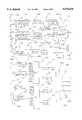
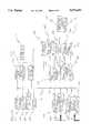
- FIGS. 3A-3Fare a block diagram of electronic components for the electrical parameter analyzer.
- the electrical parameter analyzer of the present inventionmay be packaged in a manner quite similar to the Dranetz 8000-2 energy analyzer.
- the electrical parameter analyzer 10may comprise a display/keyboard module 14 mounted on a control module 13 which in turn is supported by a cradle-type stand 12. It may be provided with a graphics printer 16 comprising a roll of thermally sensitive paper, a thermal printhead, and an appropriate paper take-up motor.
- Electrical parameter analyzer 10also has a liquid crystal display (LCD) 18 for real time display of electrical signals. Data collected by electrical parameter analyzer 10 may be recorded upon a static RAM data card 22 received within a card slot 20. Data card 22 preferably has a 68 pin connector and complies with PCMCIA standards. Data card slot 20 is equipped with a compatible 68 pin receptacle. Electrical parameter analyzer 10 also has a series of function keys 24 and a numeric keypad 26.
- LCDliquid crystal display
- the electrical parameter analyzermay have four positive voltage input terminals 28, four negative voltage terminals 29 and a ground connection terminal 31.
- voltage input terminals 28are four current probe connectors 30. This enables simultaneous monitoring of voltage and current in four analog channels.
- a digital input connector 32enables reception of four channels of digital information.
- Serial port 36may be connected to a suitable internal or external modem.
- An optional internal 2400 baud FAX/modemcan be accessed via RJIIC jack 27.
- a key feature of the inventionis program card slot 38 which receives a PCMCIA compatible 68 pin program card 40.
- Program card 40contains a solid state common memory and a physically separate solid state attribute memory.
- the common memorycontains program control code for controlling three internal microprocessors 212, 300, 400 (illustrated schematically in FIGS. 3C, 3D and 3E) to analyze electrical signals received via the above-described connectors.
- the attribute memorycontains information such as program card identification, options, purchase date, program card version and general information about the program code stored in the common memory.
- the program code on program card 40may instruct the internal microprocessors to accept digital inputs from the keypad, interpret those inputs as start/stop intervals for monitoring and recording current and voltage on four input channels, displaying the signals on LCD 18, creating a graphic record thereof on graphics display 16 and creating a machine-readable record thereof on data card 22.
- a different cardmay contain program code for analyzing harmonic distortion of voltage, current and power on four input channels and recording the results both graphically and in a text format.
- each of the microprocessorshas an associated ROM containing a stored boot routine. These ROMs initialize the microprocessors and enable them to read the program code on program card 40. All functionality and features of the instrument are in the program card code.
- Electrical parameter analyzer 10has four major subsystems as generally illustrated in block diagram form in FIGS. 3A-3F. They are the data acquisition subsystem 42 (shown partly in FIG. 3A and partly in FIG. 3B), an acquisition control processor (ACP) 44 (FIG. 3C), an I/O controller 46 (FIG. 3D) and a central processing unit 50 (FIG. 3E). An external memory card controller 442, a contrast control board 54, an LCD panel 56 and a keypad board 58 (all illustrated in FIG. 3F) are connected to central processing unit 50. There is also a power supply (not illustrated). Microprocessors 212, 300 and 400 are incorporated within ACP 44, I/O controller 46, and central processing unit 50 respectively. In the preferred embodiment described herein all three microprocessors are supplied by Motorola. Microprocessors 212 and 400 are sold under the designation MC68EC020 while microprocessor 300 is sold under the designation MC68HC11.
- data acquisition subsystem 42is connected for receiving inputs from the various terminal devices illustrated in FIG. 2.
- Positive and negative inputs from a current probe connector 30are supplied to a differential amplifier 126. It will be appreciated that there are four such differential amplifiers 126, only one of which is illustrated.
- Positive voltage inputsare supplied to three attenuators 106 (only one being illustrated), and a fourth attenuator 107.
- Negative voltage inputsare supplied to three attenuators 108 (only one being illustrated), as well as to a fourth attenuator 109.
- a range select circuit 111is connected between attenuator 107 and its associated attenuator 109.
- Output signals from attenuator pairs 106,108are applied to three corresponding differential amplifiers 112 (again, only one being illustrated).
- the output from each differential amplifier 112is supplied to a corresponding low pass filter 114 and to a pair of corresponding peak detectors 152,154 via an associated one of three lines 990.
- Output signals from voltage attenuators 107,109are similarly applied to a differential amplifier 113 which is connected to a low pass filter 115 and to a pair of peak detectors (not illustrated) identical to peak detectors 152,154 via a line 989.
- the output from each differential amplifier 126is supplied to a low pass filter 124 and to a pair of peak detectors 156,158 via an associated line 988.
- Output signals from low pass filters 114,115 and 124are applied to corresponding sample and hold circuits 120,122,123 respectively which in turn are connected via lines 991b, 991d and 991e to a multiplexer 118 (FIG. 3B). This provides for simultaneous sampling of all eight input channels.
- the output signals from low pass filters 114,115are also applied via a line 991a,991c to a multiplexer 116 (FIG. 3B) which supplies inputs to a zero crossing detector 128.
- Voltage and current samples from multiplexer 118are applied to a range detector 140 and to a variable gain amplifier 142. To summarize, the voltage and current inputs break off and travel in parallel for low frequency sampling as required for power quantity type measurements.
- High frequency processingis accomplished by a pair of multiplexers 160,162 and four sample and hold circuits 164, 166, 168 and 170 connected via lines 901-904 to a multiplexer 172.
- Multiplexer 160is supplied with inputs from peak detectors 152,154 as well as from similar pairs of peak detectors serving the other above described voltage channels.
- the four sets of current peak detectors 156,158are connected to the input side of multiplexer 162.
- High frequency samples from multiplexer 172are applied to an A/D converter 174 and thence to a FIFO 150 for application to ACP 44 via a mother board as illustrated schematically by line 993.
- Amplified voltage and current signals from variable gain amplifier 142are applied to an analog-to-digital converter 144 and then are processed by a FIFO 146 for transmission to the ACP 44 by line 993.
- a probe serial data link 148also may supply data to ACP 44, again through the mother board.
- the output from zero crossing detector 128is applied to a multiplexer 130 for transmission to a phase locked loop 132 which is connected to an acquisition control logic circuit 138.
- Acquisition control logic 138provides synchronizing signals for multiplexers 118, 172 and A/D converters 144,174.
- Phase locked loop 132may be manually controlled by keyboard commands applied via a bus line 992 to DAC 134.
- a V/F circuit 136receives the manual control signals in analog form from DAC 134, converts them to frequency adjustments and routes them to the phase locked loop via multiplexer 130.
- ACP 44The main purpose of ACP 44 is to acquire data in real time from data acquisition subsystem 42, process that data, perform calculations thereon, and transfer the results through the mother board via line 993 to the central processing unit 50.
- the memory section of ACP 44comprises a boot ROM 202, a data RAM 204, a program RAM 206, and an EEPROM 208.
- EEPROM 208stores calibration information for use by the data acquisition subsystem 42.
- microprocessor 212When electrical parameter analyzer 10 is turned on boot ROM 202 boots microprocessor 212 and passes control to CPU 50. Then, if so instructed by CPU 50, program control instructions for microprocessor 212 are read from CPU 50 and loaded into program RAM 206. Microprocessor 212 then comes under execution control of program RAM 206. If program card 40 is not installed in program card slot 38 at the time of startup, then electrical parameter analyzer 10 operates as a simple three-phase watt meter using a set of minimum logic instructions stored within boot ROM 202.
- ACP 44has a bus 83 which connects ROM 202, RAM 204, RAM 206, EEPROM 208 and microprocessor 212 to a watchdog reset circuit 210, a control signal generation circuit 214, a DUART 220, a relay control 224, an A/D converter 228, a digital input interface 234, frequency counters 244, a databus interface 246, a FIFO status interface 248 and a dual port interface 260.
- DUART 220is serviced by a 3.6864 MHz crystal oscillator 221 and by serial port 223.
- An oscillator 225generates clock signals for microprocessor 212.
- a clock circuit 240generates 1 MHz, 64 KHz and 1 KHz clocks by counting clock pulses supplied by a 4 MHz oscillator 242.
- a transducer input block 232supplies transducer signals to an analog multiplexer 230, which is connected to the input side of the A/D converter 228.
- Four channels of digital input signalsmay be applied to terminal block 32 for transfer to an optical isolation circuit 236 which is connected to digital input interface 234.
- Dual port interface 260is connected through the mother board via line 994 to a dual port RAM 430 (FIG. 3E) in central processing unit 50.
- I/O controller 46has a boot ROM 310 which communicates with microprocessor 300.
- Boot ROM 310operates in a manner similar to boot ROM 202 in that it initializes microprocessor 300 at startup. Following startup, microprocessor 300 loads program instructions from CPU 50 into a program RAM 306. These instructions are used by microprocessor to control the operations of printer 48.
- a dual port interface 314is connected via a line 995 through the mother board to a dual port RAM 424 in CPU 50. Reading of program card 40 is under control of central processing unit 50 which routes appropriate program code to ACP 44 and I/O controller 46 via the mother board and dual port RAMs 424,430 respectively.
- a bus 301 within I/O controller 46interconnects microprocessor 300 with ROM 310, program RAM 306, a temporary storage RAM 312, a parallel port 34, a DUART 316 and a printer controller 328.
- Printer controller 328controls printer 48 which in turn comprises a paper takeup motor 340 and a 320 dots-per-line thermal printer 341.
- a burn timer 326is connected to printer controller 328 for controlling the operation of thermal printer 330.
- DUART 316receives input signals from RS232 port 320 and an optional modem/fax 318.
- DUART 316operates under control of a 3.6864 MHz crystal 324.
- CPU 300operates under timing control of a 12 MHz crystal 322 and is provided with inputs from a watchdog/reset circuit 302 and a voltage monitor 304.
- central processing unit 50has its own boot ROM 402 and program RAM 404 interconnected by a data and address bus 421. These units operate in a manner similar to the above-described boot ROM and program RAM units of ACP 44 and I/O controller 46 so as to control the operation of microprocessor 400.
- Central processing unit 50also includes dual port RAMs 424, 430 which are mentioned above, as well as a non-volatile RAM 406 and a system RAM 410.
- a lithium battery 408powers non-volatile RAM 406.
- central processing unit 50Other elements of central processing unit 50 include a watchdog/reset circuit 434, a 16 MHz clock 436, a general I/O circuit 426, an audible alarm 428, a time keeper alarm 429.and a control signal generator 414.
- An LCD interface 418controls LCD frame memory 416 which in turn services LCD panel 56 (FIG. 3F) via a line 998.
- a keypad interface 412communicates with keypad board 58 via a line 997.
- a program card interface 420connects program card 40, received in program card slot 38 to bus 421 via a line 923.
- Control signal generator 414operates under control of microprocessor 400 for selectively causing program card interface 420 to address either common memory 498 or attribute memory 499 of program card 40.
- External memory card interface 432connects bus 421 to an external memory card controller 422 through a bus 996.
- External memory card controller 422accesses digitized data stored on data card 22, received in data card slot 20.
Landscapes
- Physics & Mathematics (AREA)
- General Physics & Mathematics (AREA)
- Measurement And Recording Of Electrical Phenomena And Electrical Characteristics Of The Living Body (AREA)
Abstract
Description
Claims (13)
Priority Applications (1)
| Application Number | Priority Date | Filing Date | Title |
|---|---|---|---|
| US08/201,348US5574654A (en) | 1994-02-24 | 1994-02-24 | Electrical parameter analyzer |
Applications Claiming Priority (1)
| Application Number | Priority Date | Filing Date | Title |
|---|---|---|---|
| US08/201,348US5574654A (en) | 1994-02-24 | 1994-02-24 | Electrical parameter analyzer |
Publications (1)
| Publication Number | Publication Date |
|---|---|
| US5574654Atrue US5574654A (en) | 1996-11-12 |
Family
ID=22745477
Family Applications (1)
| Application Number | Title | Priority Date | Filing Date |
|---|---|---|---|
| US08/201,348Expired - Fee RelatedUS5574654A (en) | 1994-02-24 | 1994-02-24 | Electrical parameter analyzer |
Country Status (1)
| Country | Link |
|---|---|
| US (1) | US5574654A (en) |
Cited By (49)
| Publication number | Priority date | Publication date | Assignee | Title |
|---|---|---|---|---|
| US5848247A (en)* | 1994-09-13 | 1998-12-08 | Hitachi, Ltd. | Microprocessor having PC card interface |
| US20010009019A1 (en)* | 1997-01-13 | 2001-07-19 | Micro Ear Technology, Inc., D/B/A Micro-Tech. | System for programming hearing aids |
| US6366863B1 (en)* | 1998-01-09 | 2002-04-02 | Micro Ear Technology Inc. | Portable hearing-related analysis system |
| US20030016004A1 (en)* | 2001-07-10 | 2003-01-23 | Gary Jungwirth | Apparatus for a simplified power disturbance indicator gage with learning capability options |
| US6631310B1 (en) | 2000-09-15 | 2003-10-07 | General Electric Company | Wireless engine-generator systems digital assistant |
| US20030194344A1 (en)* | 2002-04-11 | 2003-10-16 | Bob Brafford | Sterilizer monitoring and controlling system and method |
| US6668629B1 (en) | 1999-11-26 | 2003-12-30 | General Electric Company | Methods and apparatus for web-enabled engine-generator systems |
| US6888948B2 (en) | 1997-01-13 | 2005-05-03 | Micro Ear Technology, Inc. | Portable system programming hearing aids |
| US20080215264A1 (en)* | 2005-01-27 | 2008-09-04 | Electro Industries/Gauge Tech. | High speed digital transient waveform detection system and method for use in an intelligent device |
| US20080234957A1 (en)* | 2005-01-27 | 2008-09-25 | Electro Industries/Gauge Tech. | Intelligent Electronic Device and Method Thereof |
| US20080235355A1 (en)* | 2004-10-20 | 2008-09-25 | Electro Industries/Gauge Tech. | Intelligent Electronic Device for Receiving and Sending Data at High Speeds Over a Network |
| US20080312851A1 (en)* | 2004-10-20 | 2008-12-18 | Electro Industries/Gauge Tech. | Portable Power Quality Analyzer with Networking Capabilities |
| US20090228224A1 (en)* | 2005-01-27 | 2009-09-10 | Electro Industries/Gauge Tech. | Intelligent electronic device with enhanced power quality monitoring and communications capabilities |
| CN101806869A (en)* | 2010-03-22 | 2010-08-18 | 株洲南车时代电气股份有限公司 | General-purpose automatic test system for locomotive switching power supply and method thereof |
| US7787647B2 (en) | 1997-01-13 | 2010-08-31 | Micro Ear Technology, Inc. | Portable system for programming hearing aids |
| US20100324845A1 (en)* | 2005-01-27 | 2010-12-23 | Electro Industries/Gauge Tech. | Intelligent electronic device with enhanced power quality monitoring and communication capabilities |
| US8300862B2 (en) | 2006-09-18 | 2012-10-30 | Starkey Kaboratories, Inc | Wireless interface for programming hearing assistance devices |
| US8503703B2 (en) | 2000-01-20 | 2013-08-06 | Starkey Laboratories, Inc. | Hearing aid systems |
| US8620608B2 (en) | 2005-01-27 | 2013-12-31 | Electro Industries/Gauge Tech | Intelligent electronic device and method thereof |
| US20140125347A1 (en)* | 2012-03-29 | 2014-05-08 | Lg Chem, Ltd. | System for automatically recognizing battery characteristic, battery information storage device for the same, and method for automatically optimizing battery management device by using the same |
| US8797202B2 (en) | 2008-03-13 | 2014-08-05 | Electro Industries/Gauge Tech | Intelligent electronic device having circuitry for highly accurate voltage sensing |
| US8930153B2 (en) | 2005-01-27 | 2015-01-06 | Electro Industries/Gauge Tech | Metering device with control functionality and method thereof |
| US9482555B2 (en) | 2008-04-03 | 2016-11-01 | Electro Industries/Gauge Tech. | System and method for improved data transfer from an IED |
| US9891253B2 (en) | 2005-10-28 | 2018-02-13 | Electro Industries/Gauge Tech | Bluetooth-enabled intelligent electronic device |
| US9897461B2 (en) | 2015-02-27 | 2018-02-20 | Electro Industries/Gauge Tech | Intelligent electronic device with expandable functionality |
| US9989618B2 (en) | 2007-04-03 | 2018-06-05 | Electro Industries/Gaugetech | Intelligent electronic device with constant calibration capabilities for high accuracy measurements |
| US10048088B2 (en) | 2015-02-27 | 2018-08-14 | Electro Industries/Gauge Tech | Wireless intelligent electronic device |
| US10275840B2 (en) | 2011-10-04 | 2019-04-30 | Electro Industries/Gauge Tech | Systems and methods for collecting, analyzing, billing, and reporting data from intelligent electronic devices |
| US10303860B2 (en) | 2011-10-04 | 2019-05-28 | Electro Industries/Gauge Tech | Security through layers in an intelligent electronic device |
| US10345416B2 (en) | 2007-03-27 | 2019-07-09 | Electro Industries/Gauge Tech | Intelligent electronic device with broad-range high accuracy |
| US10430263B2 (en) | 2016-02-01 | 2019-10-01 | Electro Industries/Gauge Tech | Devices, systems and methods for validating and upgrading firmware in intelligent electronic devices |
| US10771532B2 (en) | 2011-10-04 | 2020-09-08 | Electro Industries/Gauge Tech | Intelligent electronic devices, systems and methods for communicating messages over a network |
| US10845399B2 (en) | 2007-04-03 | 2020-11-24 | Electro Industries/Gaugetech | System and method for performing data transfers in an intelligent electronic device |
| US10862784B2 (en) | 2011-10-04 | 2020-12-08 | Electro Industries/Gauge Tech | Systems and methods for processing meter information in a network of intelligent electronic devices |
| US10958435B2 (en) | 2015-12-21 | 2021-03-23 | Electro Industries/ Gauge Tech | Providing security in an intelligent electronic device |
| US11009922B2 (en) | 2015-02-27 | 2021-05-18 | Electro Industries/Gaugetech | Wireless intelligent electronic device |
| US11307227B2 (en) | 2007-04-03 | 2022-04-19 | Electro Industries/Gauge Tech | High speed digital transient waveform detection system and method for use in an intelligent electronic device |
| US11644490B2 (en) | 2007-04-03 | 2023-05-09 | El Electronics Llc | Digital power metering system with serial peripheral interface (SPI) multimaster communications |
| US11686594B2 (en) | 2018-02-17 | 2023-06-27 | Ei Electronics Llc | Devices, systems and methods for a cloud-based meter management system |
| US11686749B2 (en) | 2004-10-25 | 2023-06-27 | El Electronics Llc | Power meter having multiple ethernet ports |
| US11734704B2 (en) | 2018-02-17 | 2023-08-22 | Ei Electronics Llc | Devices, systems and methods for the collection of meter data in a common, globally accessible, group of servers, to provide simpler configuration, collection, viewing, and analysis of the meter data |
| US11734396B2 (en) | 2014-06-17 | 2023-08-22 | El Electronics Llc | Security through layers in an intelligent electronic device |
| US11754997B2 (en) | 2018-02-17 | 2023-09-12 | Ei Electronics Llc | Devices, systems and methods for predicting future consumption values of load(s) in power distribution systems |
| US11816465B2 (en) | 2013-03-15 | 2023-11-14 | Ei Electronics Llc | Devices, systems and methods for tracking and upgrading firmware in intelligent electronic devices |
| US11863589B2 (en) | 2019-06-07 | 2024-01-02 | Ei Electronics Llc | Enterprise security in meters |
| US12061218B2 (en) | 2008-03-13 | 2024-08-13 | Ei Electronics Llc | System and method for multi-rate concurrent waveform capture and storage for power quality metering |
| US12099468B2 (en) | 2011-10-04 | 2024-09-24 | Ei Electronics Llc | Systems and methods for collecting, analyzing, billing, and reporting data from intelligent electronic devices |
| US12260078B2 (en) | 2011-10-04 | 2025-03-25 | Ei Electronics Llc | Dynamic webpage interface for an intelligent electronic device |
| US12288058B2 (en) | 2018-09-20 | 2025-04-29 | Ei Electronics Llc | Devices, systems and methods for tracking and upgrading firmware in intelligent electronic devices |
Citations (6)
| Publication number | Priority date | Publication date | Assignee | Title |
|---|---|---|---|---|
| US4104725A (en)* | 1976-03-26 | 1978-08-01 | Norland Corporation | Programmed calculating input signal module for waveform measuring and analyzing instrument |
| US4414638A (en)* | 1981-04-30 | 1983-11-08 | Dranetz Engineering Laboratories, Inc. | Sampling network analyzer with stored correction of gain errors |
| US4589088A (en)* | 1981-02-09 | 1986-05-13 | Honeywell Inc. | Remote data gathering panel |
| US4642563A (en)* | 1985-05-28 | 1987-02-10 | Basic Measuring Instruments | Power line impulse measurement system |
| US5151866A (en)* | 1990-03-30 | 1992-09-29 | The Dow Chemical Company | High speed power analyzer |
| US5467286A (en)* | 1993-11-03 | 1995-11-14 | Square D Company | Metering unit with downloadable firmware |
- 1994
- 1994-02-24USUS08/201,348patent/US5574654A/ennot_activeExpired - Fee Related
Patent Citations (6)
| Publication number | Priority date | Publication date | Assignee | Title |
|---|---|---|---|---|
| US4104725A (en)* | 1976-03-26 | 1978-08-01 | Norland Corporation | Programmed calculating input signal module for waveform measuring and analyzing instrument |
| US4589088A (en)* | 1981-02-09 | 1986-05-13 | Honeywell Inc. | Remote data gathering panel |
| US4414638A (en)* | 1981-04-30 | 1983-11-08 | Dranetz Engineering Laboratories, Inc. | Sampling network analyzer with stored correction of gain errors |
| US4642563A (en)* | 1985-05-28 | 1987-02-10 | Basic Measuring Instruments | Power line impulse measurement system |
| US5151866A (en)* | 1990-03-30 | 1992-09-29 | The Dow Chemical Company | High speed power analyzer |
| US5467286A (en)* | 1993-11-03 | 1995-11-14 | Square D Company | Metering unit with downloadable firmware |
Cited By (90)
| Publication number | Priority date | Publication date | Assignee | Title |
|---|---|---|---|---|
| US5848247A (en)* | 1994-09-13 | 1998-12-08 | Hitachi, Ltd. | Microprocessor having PC card interface |
| US6594720B1 (en) | 1994-09-20 | 2003-07-15 | Hitachi, Ltd. | Data processing system having a PC card type interface with assigned addressing |
| US6792493B2 (en) | 1994-09-20 | 2004-09-14 | Hitachi, Ltd. | Data processing system having a card type interface with assigned addressing |
| US6851048B2 (en) | 1997-01-13 | 2005-02-01 | Micro Ear Technology, Inc. | System for programming hearing aids |
| US20010009019A1 (en)* | 1997-01-13 | 2001-07-19 | Micro Ear Technology, Inc., D/B/A Micro-Tech. | System for programming hearing aids |
| US7929723B2 (en) | 1997-01-13 | 2011-04-19 | Micro Ear Technology, Inc. | Portable system for programming hearing aids |
| US7787647B2 (en) | 1997-01-13 | 2010-08-31 | Micro Ear Technology, Inc. | Portable system for programming hearing aids |
| US7451256B2 (en) | 1997-01-13 | 2008-11-11 | Micro Ear Technology, Inc. | Portable system for programming hearing aids |
| US7054957B2 (en) | 1997-01-13 | 2006-05-30 | Micro Ear Technology, Inc. | System for programming hearing aids |
| US6888948B2 (en) | 1997-01-13 | 2005-05-03 | Micro Ear Technology, Inc. | Portable system programming hearing aids |
| US6647345B2 (en)* | 1998-01-09 | 2003-11-11 | Micro Ear Technology, Inc. | Portable hearing-related analysis system |
| US6895345B2 (en) | 1998-01-09 | 2005-05-17 | Micro Ear Technology, Inc. | Portable hearing-related analysis system |
| US6366863B1 (en)* | 1998-01-09 | 2002-04-02 | Micro Ear Technology Inc. | Portable hearing-related analysis system |
| US6668629B1 (en) | 1999-11-26 | 2003-12-30 | General Electric Company | Methods and apparatus for web-enabled engine-generator systems |
| US8503703B2 (en) | 2000-01-20 | 2013-08-06 | Starkey Laboratories, Inc. | Hearing aid systems |
| US9344817B2 (en) | 2000-01-20 | 2016-05-17 | Starkey Laboratories, Inc. | Hearing aid systems |
| US9357317B2 (en) | 2000-01-20 | 2016-05-31 | Starkey Laboratories, Inc. | Hearing aid systems |
| US6631310B1 (en) | 2000-09-15 | 2003-10-07 | General Electric Company | Wireless engine-generator systems digital assistant |
| US7106045B2 (en) | 2001-07-10 | 2006-09-12 | Uppi Corporation | Apparatus for a simplified power disturbance indicator gage with learning capability options |
| US20030016004A1 (en)* | 2001-07-10 | 2003-01-23 | Gary Jungwirth | Apparatus for a simplified power disturbance indicator gage with learning capability options |
| US7780920B2 (en) | 2002-04-11 | 2010-08-24 | Baxter International, Inc. | Sterilizer monitoring and controlling system |
| US20030194344A1 (en)* | 2002-04-11 | 2003-10-16 | Bob Brafford | Sterilizer monitoring and controlling system and method |
| US7270790B2 (en)* | 2002-04-11 | 2007-09-18 | Baxter International Inc. | Sterilizer monitoring and controlling system and method |
| US9696180B2 (en) | 2004-10-20 | 2017-07-04 | Electro Industries/Gauge Tech. | Portable power quality analyzer with networking capabilities |
| US10641618B2 (en) | 2004-10-20 | 2020-05-05 | Electro Industries/Gauge Tech | On-line web accessed energy meter |
| US10628053B2 (en) | 2004-10-20 | 2020-04-21 | Electro Industries/Gauge Tech | Intelligent electronic device for receiving and sending data at high speeds over a network |
| US11754418B2 (en) | 2004-10-20 | 2023-09-12 | Ei Electronics Llc | On-line web accessed energy meter |
| US20080235355A1 (en)* | 2004-10-20 | 2008-09-25 | Electro Industries/Gauge Tech. | Intelligent Electronic Device for Receiving and Sending Data at High Speeds Over a Network |
| US20080312851A1 (en)* | 2004-10-20 | 2008-12-18 | Electro Industries/Gauge Tech. | Portable Power Quality Analyzer with Networking Capabilities |
| US9080894B2 (en) | 2004-10-20 | 2015-07-14 | Electro Industries/Gauge Tech | Intelligent electronic device for receiving and sending data at high speeds over a network |
| US11686749B2 (en) | 2004-10-25 | 2023-06-27 | El Electronics Llc | Power meter having multiple ethernet ports |
| US20090228224A1 (en)* | 2005-01-27 | 2009-09-10 | Electro Industries/Gauge Tech. | Intelligent electronic device with enhanced power quality monitoring and communications capabilities |
| US11366145B2 (en) | 2005-01-27 | 2022-06-21 | Electro Industries/Gauge Tech | Intelligent electronic device with enhanced power quality monitoring and communications capability |
| US8666688B2 (en) | 2005-01-27 | 2014-03-04 | Electro Industries/Gauge Tech | High speed digital transient waveform detection system and method for use in an intelligent electronic device |
| US8700347B2 (en) | 2005-01-27 | 2014-04-15 | Electro Industries/Gauge Tech | Intelligent electronic device with enhanced power quality monitoring and communications capability |
| US20080215264A1 (en)* | 2005-01-27 | 2008-09-04 | Electro Industries/Gauge Tech. | High speed digital transient waveform detection system and method for use in an intelligent device |
| US20080234957A1 (en)* | 2005-01-27 | 2008-09-25 | Electro Industries/Gauge Tech. | Intelligent Electronic Device and Method Thereof |
| US8862435B2 (en) | 2005-01-27 | 2014-10-14 | Electric Industries/Gauge Tech | Intelligent electronic device with enhanced power quality monitoring and communication capabilities |
| US8930153B2 (en) | 2005-01-27 | 2015-01-06 | Electro Industries/Gauge Tech | Metering device with control functionality and method thereof |
| US20100324845A1 (en)* | 2005-01-27 | 2010-12-23 | Electro Industries/Gauge Tech. | Intelligent electronic device with enhanced power quality monitoring and communication capabilities |
| US10823770B2 (en) | 2005-01-27 | 2020-11-03 | Electro Industries/Gaugetech | Intelligent electronic device and method thereof |
| US9194898B2 (en) | 2005-01-27 | 2015-11-24 | Electro Industries/Gauge Tech | Intelligent electronic device and method thereof |
| US8190381B2 (en) | 2005-01-27 | 2012-05-29 | Electro Industries/Gauge Tech | Intelligent electronic device with enhanced power quality monitoring and communications capabilities |
| US8160824B2 (en) | 2005-01-27 | 2012-04-17 | Electro Industries/Gauge Tech | Intelligent electronic device with enhanced power quality monitoring and communication capabilities |
| US11366143B2 (en) | 2005-01-27 | 2022-06-21 | Electro Industries/Gaugetech | Intelligent electronic device with enhanced power quality monitoring and communication capabilities |
| US8078418B2 (en) | 2005-01-27 | 2011-12-13 | Electro Industries/Gauge Tech | Intelligent electronic device and method thereof |
| US9903895B2 (en) | 2005-01-27 | 2018-02-27 | Electro Industries/Gauge Tech | Intelligent electronic device and method thereof |
| US8620608B2 (en) | 2005-01-27 | 2013-12-31 | Electro Industries/Gauge Tech | Intelligent electronic device and method thereof |
| US9891253B2 (en) | 2005-10-28 | 2018-02-13 | Electro Industries/Gauge Tech | Bluetooth-enabled intelligent electronic device |
| US8300862B2 (en) | 2006-09-18 | 2012-10-30 | Starkey Kaboratories, Inc | Wireless interface for programming hearing assistance devices |
| US10345416B2 (en) | 2007-03-27 | 2019-07-09 | Electro Industries/Gauge Tech | Intelligent electronic device with broad-range high accuracy |
| US10845399B2 (en) | 2007-04-03 | 2020-11-24 | Electro Industries/Gaugetech | System and method for performing data transfers in an intelligent electronic device |
| US9989618B2 (en) | 2007-04-03 | 2018-06-05 | Electro Industries/Gaugetech | Intelligent electronic device with constant calibration capabilities for high accuracy measurements |
| US11644490B2 (en) | 2007-04-03 | 2023-05-09 | El Electronics Llc | Digital power metering system with serial peripheral interface (SPI) multimaster communications |
| US11635455B2 (en) | 2007-04-03 | 2023-04-25 | El Electronics Llc | System and method for performing data transfers in an intelligent electronic device |
| US11307227B2 (en) | 2007-04-03 | 2022-04-19 | Electro Industries/Gauge Tech | High speed digital transient waveform detection system and method for use in an intelligent electronic device |
| US12061218B2 (en) | 2008-03-13 | 2024-08-13 | Ei Electronics Llc | System and method for multi-rate concurrent waveform capture and storage for power quality metering |
| US8797202B2 (en) | 2008-03-13 | 2014-08-05 | Electro Industries/Gauge Tech | Intelligent electronic device having circuitry for highly accurate voltage sensing |
| US9482555B2 (en) | 2008-04-03 | 2016-11-01 | Electro Industries/Gauge Tech. | System and method for improved data transfer from an IED |
| CN101806869A (en)* | 2010-03-22 | 2010-08-18 | 株洲南车时代电气股份有限公司 | General-purpose automatic test system for locomotive switching power supply and method thereof |
| US10862784B2 (en) | 2011-10-04 | 2020-12-08 | Electro Industries/Gauge Tech | Systems and methods for processing meter information in a network of intelligent electronic devices |
| US10771532B2 (en) | 2011-10-04 | 2020-09-08 | Electro Industries/Gauge Tech | Intelligent electronic devices, systems and methods for communicating messages over a network |
| US12099468B2 (en) | 2011-10-04 | 2024-09-24 | Ei Electronics Llc | Systems and methods for collecting, analyzing, billing, and reporting data from intelligent electronic devices |
| US12260078B2 (en) | 2011-10-04 | 2025-03-25 | Ei Electronics Llc | Dynamic webpage interface for an intelligent electronic device |
| US12309047B2 (en) | 2011-10-04 | 2025-05-20 | Ei Electronics Llc | Systems and methods for processing meter information in a network of intelligent electronic devices |
| US12332967B2 (en) | 2011-10-04 | 2025-06-17 | Ei Electronics Llc | Systems and methods for collecting, analyzing, billing, and reporting data from intelligent electronic devices |
| US10275840B2 (en) | 2011-10-04 | 2019-04-30 | Electro Industries/Gauge Tech | Systems and methods for collecting, analyzing, billing, and reporting data from intelligent electronic devices |
| US10303860B2 (en) | 2011-10-04 | 2019-05-28 | Electro Industries/Gauge Tech | Security through layers in an intelligent electronic device |
| US9182450B2 (en)* | 2012-03-29 | 2015-11-10 | Lg Chem, Ltd. | System for automatically recognizing battery characteristic, battery information storage device for the same, and method for automatically optimizing battery management device by using the same |
| US20140125347A1 (en)* | 2012-03-29 | 2014-05-08 | Lg Chem, Ltd. | System for automatically recognizing battery characteristic, battery information storage device for the same, and method for automatically optimizing battery management device by using the same |
| US11816465B2 (en) | 2013-03-15 | 2023-11-14 | Ei Electronics Llc | Devices, systems and methods for tracking and upgrading firmware in intelligent electronic devices |
| US12067090B2 (en) | 2014-06-17 | 2024-08-20 | Ei Electronics Llc | Security through layers in an intelligent electronic device |
| US11734396B2 (en) | 2014-06-17 | 2023-08-22 | El Electronics Llc | Security through layers in an intelligent electronic device |
| US11644341B2 (en) | 2015-02-27 | 2023-05-09 | El Electronics Llc | Intelligent electronic device with hot swappable battery |
| US9897461B2 (en) | 2015-02-27 | 2018-02-20 | Electro Industries/Gauge Tech | Intelligent electronic device with expandable functionality |
| US10274340B2 (en) | 2015-02-27 | 2019-04-30 | Electro Industries/Gauge Tech | Intelligent electronic device with expandable functionality |
| US10048088B2 (en) | 2015-02-27 | 2018-08-14 | Electro Industries/Gauge Tech | Wireless intelligent electronic device |
| US11641052B2 (en) | 2015-02-27 | 2023-05-02 | El Electronics Llc | Wireless intelligent electronic device |
| US11009922B2 (en) | 2015-02-27 | 2021-05-18 | Electro Industries/Gaugetech | Wireless intelligent electronic device |
| US10739162B2 (en) | 2015-02-27 | 2020-08-11 | Electro Industries/Gauge Tech | Intelligent electronic device with surge supression |
| US12087998B2 (en) | 2015-02-27 | 2024-09-10 | Ei Electronics Llc | Wireless intelligent electronic device |
| US10958435B2 (en) | 2015-12-21 | 2021-03-23 | Electro Industries/ Gauge Tech | Providing security in an intelligent electronic device |
| US11870910B2 (en) | 2015-12-21 | 2024-01-09 | Ei Electronics Llc | Providing security in an intelligent electronic device |
| US12212689B2 (en) | 2015-12-21 | 2025-01-28 | Ei Electronics Llc | Providing security in an intelligent electronic device |
| US10430263B2 (en) | 2016-02-01 | 2019-10-01 | Electro Industries/Gauge Tech | Devices, systems and methods for validating and upgrading firmware in intelligent electronic devices |
| US11734704B2 (en) | 2018-02-17 | 2023-08-22 | Ei Electronics Llc | Devices, systems and methods for the collection of meter data in a common, globally accessible, group of servers, to provide simpler configuration, collection, viewing, and analysis of the meter data |
| US11754997B2 (en) | 2018-02-17 | 2023-09-12 | Ei Electronics Llc | Devices, systems and methods for predicting future consumption values of load(s) in power distribution systems |
| US11686594B2 (en) | 2018-02-17 | 2023-06-27 | Ei Electronics Llc | Devices, systems and methods for a cloud-based meter management system |
| US12288058B2 (en) | 2018-09-20 | 2025-04-29 | Ei Electronics Llc | Devices, systems and methods for tracking and upgrading firmware in intelligent electronic devices |
| US11863589B2 (en) | 2019-06-07 | 2024-01-02 | Ei Electronics Llc | Enterprise security in meters |
Similar Documents
| Publication | Publication Date | Title |
|---|---|---|
| US5574654A (en) | Electrical parameter analyzer | |
| US4881184A (en) | Turbine monitoring apparatus | |
| US5432705A (en) | Administrative computer and testing apparatus | |
| US5804971A (en) | Modular card based meter | |
| JPS5832430B2 (en) | electronic cash register | |
| EP1005708B1 (en) | Circuit board arrangement | |
| JP2001033562A (en) | Data logger and vibration measurement system | |
| JPH04144051A (en) | Data processing device for gas chromatograph mass spectrometer | |
| JPS63204151A (en) | Analysis equipment | |
| Fowler | Amplitude measures of operant response: Implementation with Apple Pascal | |
| JP2612341B2 (en) | Power supply circuit inspection method | |
| JP2566645B2 (en) | Recording card system for temperature and humidity | |
| JPS58101355A (en) | Alarm display method | |
| KR0152889B1 (en) | Simple function inspection method for digital protection relay | |
| JPH023125B2 (en) | ||
| JPS58216929A (en) | Portable type engine performance tester | |
| KR930010819A (en) | Remote Metering Device and Method for Variable Rate Application | |
| JPH03131722A (en) | Data logger device | |
| Pickens et al. | Use of a distributed processing data‐acquisition system to control an acoustic spectrometer | |
| JPH0662375U (en) | Power measurement system | |
| Dockswell et al. | Well begun is half done(testing technology) | |
| Nagel et al. | Design and implementation of a wireless data acquisition system | |
| Amplifier | MODEL SR830 | |
| JP3353426B2 (en) | Analog type sensor characteristic tester | |
| El-Dhaher et al. | An interactive microprocessor-based system for the processing of photoacoustic spectrometer data |
Legal Events
| Date | Code | Title | Description |
|---|---|---|---|
| AS | Assignment | Owner name:DRANETZ TECHNOLOGIES, INC., NEW JERSEY Free format text:ASSIGNMENT OF ASSIGNORS INTEREST;ASSIGNORS:BINGHAM, RICHARD PAUL;IGNALL, ROSS MATTHEW;BERNARD, PAUL JOSEPH;REEL/FRAME:006924/0573 Effective date:19940223 | |
| FPAY | Fee payment | Year of fee payment:4 | |
| SULP | Surcharge for late payment | ||
| REMI | Maintenance fee reminder mailed | ||
| AS | Assignment | Owner name:FLEET NATIONAL BANK, AS AGENT, MASSACHUSETTS Free format text:PATENT COLLATERAL ASSIGNMENT AND SECURITY AGREEMENT;ASSIGNOR:DRANETZ TECHNOLOGIES, INC.;REEL/FRAME:011497/0438 Effective date:20000929 | |
| AS | Assignment | Owner name:SILICON VALLEY BANK DBA SILICON VALLEY EAST, CALIF Free format text:SECURITY AGREEMENT;ASSIGNOR:DRANETZ, TECHNOLOGIES, INC.;REEL/FRAME:013333/0363 Effective date:20021223 | |
| REMI | Maintenance fee reminder mailed | ||
| LAPS | Lapse for failure to pay maintenance fees | ||
| LAPS | Lapse for failure to pay maintenance fees | Free format text:PATENT EXPIRED FOR FAILURE TO PAY MAINTENANCE FEES (ORIGINAL EVENT CODE: EXP.); ENTITY STATUS OF PATENT OWNER: LARGE ENTITY | |
| STCH | Information on status: patent discontinuation | Free format text:PATENT EXPIRED DUE TO NONPAYMENT OF MAINTENANCE FEES UNDER 37 CFR 1.362 | |
| FP | Lapsed due to failure to pay maintenance fee | Effective date:20041112 |