US5574623A - Device panel with in-molded applique - Google Patents
Device panel with in-molded appliqueDownload PDFInfo
- Publication number
- US5574623A US5574623AUS08/395,966US39596695AUS5574623AUS 5574623 AUS5574623 AUS 5574623AUS 39596695 AUS39596695 AUS 39596695AUS 5574623 AUS5574623 AUS 5574623A
- Authority
- US
- United States
- Prior art keywords
- molded
- panel
- reverse side
- molded portion
- panel structure
- Prior art date
- Legal status (The legal status is an assumption and is not a legal conclusion. Google has not performed a legal analysis and makes no representation as to the accuracy of the status listed.)
- Expired - Fee Related
Links
- 230000002441reversible effectEffects0.000claimsabstractdescription39
- 238000000034methodMethods0.000claimsabstractdescription20
- 238000000465mouldingMethods0.000claimsabstractdescription12
- 230000004888barrier functionEffects0.000claimsabstractdescription10
- 230000008569processEffects0.000claimsabstractdescription7
- 239000002991molded plasticSubstances0.000claimsdescription3
- 238000007789sealingMethods0.000claimsdescription3
- 230000002411adverseEffects0.000claimsdescription2
- 238000000926separation methodMethods0.000claimsdescription2
- 239000004033plasticSubstances0.000abstractdescription15
- 239000000463materialSubstances0.000abstractdescription9
- 238000002347injectionMethods0.000abstractdescription8
- 239000007924injectionSubstances0.000abstractdescription8
- 238000001746injection mouldingMethods0.000abstractdescription6
- 230000000717retained effectEffects0.000abstractdescription3
- 238000005406washingMethods0.000description7
- 239000012528membraneSubstances0.000description5
- 239000000853adhesiveSubstances0.000description3
- 230000001070adhesive effectEffects0.000description3
- 230000008901benefitEffects0.000description3
- 125000006850spacer groupChemical group0.000description3
- 238000005538encapsulationMethods0.000description2
- 230000004927fusionEffects0.000description2
- 239000007788liquidSubstances0.000description2
- XLYOFNOQVPJJNP-UHFFFAOYSA-NwaterSubstancesOXLYOFNOQVPJJNP-UHFFFAOYSA-N0.000description2
- 230000009471actionEffects0.000description1
- 230000003466anti-cipated effectEffects0.000description1
- 230000015572biosynthetic processEffects0.000description1
- 239000011248coating agentSubstances0.000description1
- 238000000576coating methodMethods0.000description1
- 238000011161developmentMethods0.000description1
- 230000018109developmental processEffects0.000description1
- 230000008030eliminationEffects0.000description1
- 238000003379elimination reactionMethods0.000description1
- 230000010354integrationEffects0.000description1
- 238000005304joiningMethods0.000description1
- 238000004519manufacturing processMethods0.000description1
- 238000012986modificationMethods0.000description1
- 230000004048modificationEffects0.000description1
- 230000008520organizationEffects0.000description1
- 239000002245particleSubstances0.000description1
- 230000002035prolonged effectEffects0.000description1
- 230000009467reductionEffects0.000description1
- 230000003014reinforcing effectEffects0.000description1
- 230000004044responseEffects0.000description1
- 239000007787solidSubstances0.000description1
- 238000005728strengtheningMethods0.000description1
Images

Classifications
- F—MECHANICAL ENGINEERING; LIGHTING; HEATING; WEAPONS; BLASTING
- F24—HEATING; RANGES; VENTILATING
- F24C—DOMESTIC STOVES OR RANGES ; DETAILS OF DOMESTIC STOVES OR RANGES, OF GENERAL APPLICATION
- F24C7/00—Stoves or ranges heated by electric energy
- F24C7/08—Arrangement or mounting of control or safety devices
- F24C7/082—Arrangement or mounting of control or safety devices on ranges, e.g. control panels, illumination
- B—PERFORMING OPERATIONS; TRANSPORTING
- B29—WORKING OF PLASTICS; WORKING OF SUBSTANCES IN A PLASTIC STATE IN GENERAL
- B29C—SHAPING OR JOINING OF PLASTICS; SHAPING OF MATERIAL IN A PLASTIC STATE, NOT OTHERWISE PROVIDED FOR; AFTER-TREATMENT OF THE SHAPED PRODUCTS, e.g. REPAIRING
- B29C33/00—Moulds or cores; Details thereof or accessories therefor
- B29C33/0077—Moulds or cores; Details thereof or accessories therefor characterised by the configuration of the mould filling gate ; accessories for connecting the mould filling gate with the filling spout
- B—PERFORMING OPERATIONS; TRANSPORTING
- B29—WORKING OF PLASTICS; WORKING OF SUBSTANCES IN A PLASTIC STATE IN GENERAL
- B29C—SHAPING OR JOINING OF PLASTICS; SHAPING OF MATERIAL IN A PLASTIC STATE, NOT OTHERWISE PROVIDED FOR; AFTER-TREATMENT OF THE SHAPED PRODUCTS, e.g. REPAIRING
- B29C70/00—Shaping composites, i.e. plastics material comprising reinforcements, fillers or preformed parts, e.g. inserts
- B29C70/68—Shaping composites, i.e. plastics material comprising reinforcements, fillers or preformed parts, e.g. inserts by incorporating or moulding on preformed parts, e.g. inserts or layers, e.g. foam blocks
- B29C70/78—Moulding material on one side only of the preformed part
- H—ELECTRICITY
- H01—ELECTRIC ELEMENTS
- H01H—ELECTRIC SWITCHES; RELAYS; SELECTORS; EMERGENCY PROTECTIVE DEVICES
- H01H13/00—Switches having rectilinearly-movable operating part or parts adapted for pushing or pulling in one direction only, e.g. push-button switch
- H01H13/70—Switches having rectilinearly-movable operating part or parts adapted for pushing or pulling in one direction only, e.g. push-button switch having a plurality of operating members associated with different sets of contacts, e.g. keyboard
- H01H13/702—Switches having rectilinearly-movable operating part or parts adapted for pushing or pulling in one direction only, e.g. push-button switch having a plurality of operating members associated with different sets of contacts, e.g. keyboard with contacts carried by or formed from layers in a multilayer structure, e.g. membrane switches
- H—ELECTRICITY
- H02—GENERATION; CONVERSION OR DISTRIBUTION OF ELECTRIC POWER
- H02B—BOARDS, SUBSTATIONS OR SWITCHING ARRANGEMENTS FOR THE SUPPLY OR DISTRIBUTION OF ELECTRIC POWER
- H02B15/00—Supervisory desks or panels for centralised control or display
- H—ELECTRICITY
- H01—ELECTRIC ELEMENTS
- H01H—ELECTRIC SWITCHES; RELAYS; SELECTORS; EMERGENCY PROTECTIVE DEVICES
- H01H2223/00—Casings
- H01H2223/002—Casings sealed
- H—ELECTRICITY
- H01—ELECTRIC ELEMENTS
- H01H—ELECTRIC SWITCHES; RELAYS; SELECTORS; EMERGENCY PROTECTIVE DEVICES
- H01H2223/00—Casings
- H01H2223/01—Mounting on appliance
- H01H2223/014—Mounting on appliance located in recess
- H—ELECTRICITY
- H01—ELECTRIC ELEMENTS
- H01H—ELECTRIC SWITCHES; RELAYS; SELECTORS; EMERGENCY PROTECTIVE DEVICES
- H01H2229/00—Manufacturing
- H01H2229/044—Injection moulding
- H01H2229/048—Insertion moulding
Definitions
- the present inventionrelates to a molded assembly and a method for producing a molded assembly.
- the molded assemblyincludes an applique or face panel which is in-molded in an injection molded process.
- Switches, lamps, and other devices which are used as indicators, controls or displaysare an essential component of many appliances and devices. It is often an important design consideration that such devices be efficiently and inexpensively produced with a high degree of reliability and to provide ease of assembly or integration into the particular device or appliance. Further reference will be made to switches although it should be understood that the discussion of devices is intended to be interpreted broadly and to include such devices as displays, indicator lamps and other such devices.
- switches used with an appliancemay be found on a number of devices either in the office or at home. Such devices may include industrial machines, computers, photo copiers, household appliances such as microwave ovens, stoves, washing machines and dryers. These switches are by no means limited to stationary equipment but may also be found on vehicles such as automobiles, boats, jettskis as well as other devices including exercise equipment and vending equipment.
- switchesare available which are discreet components which plug into or connect to a switch panel. These discreet components often project though an opening in the panel with the body or the mechanical components of the switch being positioned behind the panel. While this type of switch is feasible for some applications, many applications require an integrated switch.
- An integrated switchis integrated into the surface of the control panel thereby eliminating an opening through the panel surface. The elimination of the opening through the panel surface improves maintainability and reliability by preventing the buildup of material in the switch which may enter the switch though the opening in the panel.
- the dome switchincludes a surface membrane which provides graphical representations of switches and appropriate indicia or text identifying the switch or various switch conditions.
- a domed structureis positioned behind the membrane and a mechanical component of the switch is positioned behind the dome.
- This type of dome switchprovides a barrier between the operator and the switch components thereby improving the reliability of the switch.
- This type of switchhowever, has a problem in that after numerous actuations, the dome portion of the switch may fail thereby requiring replacement of the switch. Therefore, it would be desirable to provide a switch which eliminates this mechanical operating aspect.
- a face appliqueis reverse printed with the control graphics and indicia to represent to the user a familiar mechanical type switch.
- a panel circuit including switch circuityis attached to the reverse side of the face applique which is in turn attached to the appliance by means of an appropriate adhesive.
- a portion of circuitryextends from the panel circuit to provide a connector between the panel circuit and the circuitry in the appliance.
- a general object which is satisfied by the inventionis to provide a method of molding a touch panel into a molded assembly to provide a single assembly which may be attached to an appliance or related device.
- Another object which is satisfied by the inventionis to provide a molded assembly in accordance with the methods taught herein.
- Yet another object which is satisfied by the inventionis to provide a molded assembly which at least partially encapsulates a touch panel without reducing the integrity of the device associated with the touch panel.
- the present inventionenvisions a method of producing a molded assembly which at least partially encapsulates a touch panel structure.
- the methodincludes providing a touch panel structure which has a front side, a reverse side and an edge extending therebetween.
- a panel circuitis attached to the panel structure and includes at least one device.
- the panelis positioned in a cavity of a plastic injection mold which includes at least one hollow shutoff positioned relative to the device on the touch panel. When the mold is closed, a rim portion of the hollow shutoff is positioned against the reverse side of the panel spaced away from the device so as to at least partially shield the portion of the panel containing the device from the injection molding environment.
- the present inventionalso envisions a product produced by this method.
- the present inventionalso envisions a molded assembly which includes a touch panel in which the touch panel is retained in a molded portion and the devices associated with the touch panel are not degraded during the molding process.
- a windowis provided on the reverse side of the touch panel.
- a barrier materialmay be applied to the reverse side of the panel prior to molding so as to form a seal between the molded portion and the touch panel in the area of the window positioned relative to the device.
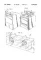
- FIG. 1is a perspective view of a washing machine employing a molded assembly of the present invention
- FIG. 2is a perspective view of a combination range and oven employing a molded assembly of the present invention
- FIG. 3is an enlarged, partial fragmentary, perspective view of a molded assembly of the present invention which incorporates several devices;
- FIG. 4is a partial fragmentary plan view of a reverse side of the molded assembly as shown in FIG. 3;
- FIG. 5is an enlarged, partial fragmentary, cross sectional view of the molded assembly taken along line 5--5 in FIG. 4;
- FIG. 6is an enlarged, partial fragmentary, cross sectional view of the molded assembly generally taken along line 6--6 in FIG. 4 and in accordance with the present invention retained in a cavity of an injection molding mold prior to injection of molten plastic therein.
- appliancesa washing machine 20 as shown in FIG. 1 and a combination range and stove 22 as shown in FIG. 2 employ a molded assembly 24.
- the molded assembly 24includes a face applique 26 and a molded portion 28.
- the molded assembly 24provides a touch control panel to operate the respective appliance 20, 22.
- FIGS. 1 and 2are illustrative of two typical yet somewhat extreme conditions in which such a touch control panel must function.
- the environmentmay include heated water or steam which is vented or may escape from the washing machine.
- such appliances combining a range and oven 22often include a vent 30 positioned between the control panel 24 and the range top 32 which vents heated air from the oven portion 34. In this situation, the touch control panel 24 is exposed to prolonged elevated temperatures as the heated air is exhausted from the oven 34 through the vent 30.
- FIG. 3provides a substantially enlarged view of a portion of the molded assembly 24 removed from the appliances 20, 22. It is this molded assembly 24 and the method of producing this assembly which are the objects of the invention. In order to more fully describe the method and article of the present invention, further reference is made to FIGS. 4-6.
- the molded assembly 24includes a plurality of controls 40 shown on the face applique 26.
- the controls 40 as shown in FIG. 3are shown in FIG. 4 as components or devices 41 connected to panel circuitry 42.
- the devices 41are generally shown as block elements.
- the controls 40are shown in a grouping in FIG. 3 and as discreet switch type components 41 in FIGS.
- the molded assemblyincludes a panel structure 44 which is at least partially encapsulated by the molded portion 28.
- the panel structure 44includes a front side 46, a reverse side 48, and an edge 50 therebetween.
- the molded portion 28is generally molded over the reverse side 48 and abuts at least a portion of the edge 50 of the planar structure 44.
- the devices 41are associated with the panel structure 44 as will be described in greater detail hereinbelow.
- the molded portion 28defines a window 52 which exposes an area of the reverse side 48 of the panel structure 44.
- the window 52is intentionally positioned in the molded portion 28 corresponding to the location of the devices 41 for preventing the molded plastic of the molded portion 28 from adversely affecting the devices.
- the area of the window 52is defined as being slightly larger than the area occupied one or more devices 41 such that a perimeter 54 of the window 52 is spaced away (see dimension line 56) from an outer edge 58 of the devices 41 associated with the panel structure 44.
- the method of the inventionincludes positioning the panel structure 44 in a plastic injection mold 60.
- the mold 60includes a front portion 62 and a rear portion 64.
- the front and rear portions 62, 64define a cavity 66 therebetween.
- Sufficient clearanceis provided between the mold portions 62, 64 for the panel structure 44 to be positioned therein.
- the panel structure 44is positioned relative to one of the mold portions 62, 64 and the other mold portion is brought into position to enclose the panel structure in the cavity 66.
- Locator pinsmay be provided on one of the portions 62, 64 and corresponding apertures (not shown) may be provided on the panel structure 44 to provide positive positioning of the panel structure 44 relative to the mold 60.
- molten plastic(diagrammatically represented by arrows 68) is injected into the cavity 66 and against the panel structure 44.
- the injected plasticpresses against the reverse side 48 to expel air from between the face applique 26 and the mold portion 62 thereby further assuring positive positioning of the panel structure 44 in the mold 60.
- the molten plasticfills the connected areas of the cavity 66 thereby in-molding the panel structure 44 into the molded portion 28.
- the hollow shutoffs 70include a rim 72.
- the area 74 defined by the rim 72corresponds to the window 52.
- a dimension 78 between the rim 72 and the outer edge 58 of the device 40provides a space which corresponds to the resulting space 56 between the perimeter 54 of the window 52 and the outer edge 58 of the device 40.
- the dimensional difference spacing the rim 72 away from a corresponding area related to the deviceresults in the formation of the window 52 in the final molded portion 28.
- the molding of the windows 52 and the use of the hollow shutoffs 70is important such that the area of the panel section 44 occupied by the devices 40 is protected from the injection molding environment.
- the injection molding environmentincludes, but is not limited to, the compressive mold clamping forces applied to the front side 46 as well as the reverse side 48 of the panel structure. Additionally, by sheltering or shielding the portion of the panel structure 44 occupied by the device 41, the device 41 is not subjected to the same elevated temperature as it would be if molten plastic were applied directly to the reverse surface 48 of the panel 44.
- the protection of the devices 41results in preventing failure, fusing, or other mechanical or electrical problems in the devices 41.
- the panel structure 44includes several layers which are combined in order to provide the resulted panel structure 44 which is in-molded into the molded portion 28.
- the panel structureincludes the face applique 26 which has a first surface 90 generally defined by the front side 46 of the panel structure 44 and a second surface 92 opposite the first surface 90.
- the second surface 92is reverse printed 26 so as to protect the printing from wear.
- a back panel 94is positioned opposite the front applique 26 and defines the reverse side 48 of the panel structure 44.
- the devices 41are sandwiched between the face applique 26 and the back panel 94.
- the panel circuit layer 42is positioned between the face applique 26 and the back panel 94 and contains or is coupled to the devices 41.
- the circuit layer 42 in the form of a connector ribbon cable 98projects through the back panel portion 94.
- a spacer 104generally having the same thickness dimension as the circuit layer 42 is positioned in order to maintain a consistent overall thickness dimension of the panel structure 44.
- a window 52is also formed around the ribbon cable 98 as it protrudes from the reverse side 48 of the assembly 24.
- the circuit layer 42includes two membrane sheets 100, 102 with circuitry and spacer 104 positioned thereon or therebetween.
- Other forms of the circuit layer 42may be used in this application as well as directly applying the circuitry to the face applique 26. In the present illustrated embodiment, however, the spacer 104 is applied to or positioned between the membranes 100, 102.
- the back panel 94is a generally rigid structure which provides a strengthening and reinforcing function in the panel structure 44. As shown in FIG. 5, an edge 106 of the back panel 94 extends away from a perimeter 108 of the face applique 26. The extending edge 106 defines a lip portion 110 of the panel 94. When the molded portion 28 is molded over the panel structure 44 plastic overlaps the lip to at least partially encapsulate the back panel 94. This partial encapsulation provides added structural connection between the molded portion 28 and the panel structure 44.
- the molded plastic overlapping the lip 110 and abutting the perimeter 108 of the face applique 26can be fused with the face applique 26 upon selecting the appropriate materials to create the fusion to create a fused are 109 joining the materials of the overlapping lip 110 and the perimeter 108 of the face applique 26.
- the edge of the face applique 26 molded into the molded portion 28is level with a corresponding edge of the molded portion 28 resulting in no lip to accumulate liquid or particles or to allow liquid to seep between the panel structure and the molded portion by capillary action.
- the fusion of the materials in the fused area 109 between the molded portion 28 and the panel structure 44prevents separation of the face applique 26 from the assembly 24.
- one of the many advantages of the inventionis to securely retain the face applique 26 on the molded assembly 24 to prevent the face applique from lifting off the appliance as may occur in prior art touch panels.
- An additional considerationis to at least partially encapsulate the panel structure 44 in the molded portion 28 so as to essentially hermetically seal the circuitry from the ambient environment.
- the window areas 52are not sealed by the molded portion 28.
- a sealing moisture barrier 112may be applied to the reverse side 48 of the panel structure 44.
- the area of the reverse side 48 within the window 52is still sealed by virtue of the moisture barrier coating 112.
- the moisture barriereffectively providing a complete water seal and encapsulation of the switch circuitry for uses such as in the boating and other marine devices such as jettskis, and other devices.
- the panel structure 44is in-molded into a molded portion 28.
- the panel structure 44is placed into a plastic injection mold 60 which includes a portion 64 which abuts the reverse side 48 which has a hollow shutoff 70.
- the hollow shutoff 70is positioned over the reverse side 48.
- the hollow shutoff 70effectively protects or shields the shutoff area which includes the devices 41 thereby preventing fusing or mechanical deformation of the circuitry in the devices 41 or other damage to the device during the injection molding process.
- molten plastic 68When molten plastic 68 is injected into the mold cavity 66 it presses against the reverse side 48 and thereby presses the front side 46 of the applique 26 against the abutting portion of the mold 62. In this manner, the gate or gates 114 are positioned centrally so as to force the front side 46 of the panel structure 44 against the mold 62. After injection of the plastic, the mold portions 62, 64 are disengaged resulting in the finished assembly 24 in which the panel structure is at least partially encapsulated by the molded portion 28.
Landscapes
- Engineering & Computer Science (AREA)
- Mechanical Engineering (AREA)
- Chemical & Material Sciences (AREA)
- Power Engineering (AREA)
- Composite Materials (AREA)
- Combustion & Propulsion (AREA)
- General Engineering & Computer Science (AREA)
- Injection Moulding Of Plastics Or The Like (AREA)
Abstract
Description
Claims (14)
Priority Applications (2)
| Application Number | Priority Date | Filing Date | Title |
|---|---|---|---|
| US08/395,966US5574623A (en) | 1995-02-28 | 1995-02-28 | Device panel with in-molded applique |
| US08/583,967US5721666A (en) | 1995-02-28 | 1996-01-11 | Device panel with in-molded applique |
Applications Claiming Priority (1)
| Application Number | Priority Date | Filing Date | Title |
|---|---|---|---|
| US08/395,966US5574623A (en) | 1995-02-28 | 1995-02-28 | Device panel with in-molded applique |
Related Child Applications (1)
| Application Number | Title | Priority Date | Filing Date |
|---|---|---|---|
| US08/583,967Continuation-In-PartUS5721666A (en) | 1995-02-28 | 1996-01-11 | Device panel with in-molded applique |
Publications (1)
| Publication Number | Publication Date |
|---|---|
| US5574623Atrue US5574623A (en) | 1996-11-12 |
Family
ID=23565302
Family Applications (1)
| Application Number | Title | Priority Date | Filing Date |
|---|---|---|---|
| US08/395,966Expired - Fee RelatedUS5574623A (en) | 1995-02-28 | 1995-02-28 | Device panel with in-molded applique |
Country Status (1)
| Country | Link |
|---|---|
| US (1) | US5574623A (en) |
Cited By (16)
| Publication number | Priority date | Publication date | Assignee | Title |
|---|---|---|---|---|
| GB2309004A (en)* | 1996-01-11 | 1997-07-16 | Master Molded Products Coporat | Device panel with in-moulded applique |
| US6137072A (en)* | 1999-05-26 | 2000-10-24 | Ferro Corporation | Control panel |
| US20030121767A1 (en)* | 2001-11-20 | 2003-07-03 | Caldwell David W. | Molded/integrated touch switch/control panel assembly and method for making same |
| US20030196460A1 (en)* | 2002-04-17 | 2003-10-23 | Lyu Jae Chul | Set of washing machine and dryer and rear cover assembly thereof |
| US20040013851A1 (en)* | 1998-03-23 | 2004-01-22 | Kessler Ronald N. | Universal mat with removable strips |
| US20040223171A1 (en)* | 2003-05-09 | 2004-11-11 | Fuji Xerox Co., Ltd. | Image forming apparatus |
| US20050061649A1 (en)* | 2003-09-22 | 2005-03-24 | Malcolm Howie | Membrane switch with rigid fascia |
| US20050210926A1 (en)* | 2004-03-25 | 2005-09-29 | Lg Electronics Inc. | Control panel assembly for washing machine |
| DE102004047516A1 (en)* | 2004-09-28 | 2006-04-06 | Carl Freudenberg Kg | Sensor arrangement and uses of a sensor arrangement |
| US20080028002A1 (en)* | 2006-07-27 | 2008-01-31 | Barkeloo Jason E | Content publishing system and method |
| US20080027750A1 (en)* | 2006-07-27 | 2008-01-31 | Barkeloo Jason E | System and method for digital rights management |
| US20080091716A1 (en)* | 2006-10-11 | 2008-04-17 | Barkeloo Jason E | Open source publishing system and method |
| US20080140610A1 (en)* | 2006-10-11 | 2008-06-12 | Barkeloo Jason E | System and method for repurposing printed content to interact with digital content |
| US20080273016A1 (en)* | 2007-05-04 | 2008-11-06 | Electrolux Home Products, Inc. | Integrated touch-screen control panel for a washing appliance and method for producing the same |
| US20120074606A1 (en)* | 2010-09-29 | 2012-03-29 | Bsh Bosch Und Siemens Hausgerate Gmbh | Injection moulding method for optional manufacturing of moulded parts with or without a breakthrough |
| US20140252688A1 (en)* | 2007-04-20 | 2014-09-11 | T-Ink, Inc. | In-molded resistive and shielding elements |
Citations (9)
| Publication number | Priority date | Publication date | Assignee | Title |
|---|---|---|---|---|
| US4028509A (en)* | 1975-08-29 | 1977-06-07 | Hughes Aircraft Company | Simplified tabulator keyboard assembly for use in watch/calculator having transparent foldable flexible printed circuit board with contacts and actuator indicia |
| US4145584A (en)* | 1976-04-28 | 1979-03-20 | Otterlei Jon L | Flexible keyboard switch with integral spacer protrusions |
| US4387127A (en)* | 1980-05-12 | 1983-06-07 | Ralph Ogden | Membrane switch control panel arrangement and label assembly for labeling same |
| US4804569A (en)* | 1987-05-19 | 1989-02-14 | Yugen Kaisha Arisawa | Unit tile |
| US4917927A (en)* | 1988-05-26 | 1990-04-17 | Katsutoshi Sakaitani | Synthetic resin moldings and method for the manufacture thereof |
| US5264172A (en)* | 1991-11-08 | 1993-11-23 | Kaumagraph Flint Corporation | Method of making a molded applique product |
| US5280146A (en)* | 1990-10-30 | 1994-01-18 | Teikoku Tsushin Kogyo Co., Ltd. | Push-button switch, keytop, and method of manufacturing the keytop |
| US5285038A (en)* | 1993-01-19 | 1994-02-08 | Delco Electronics Corporation | Lighted momentary push-button switch assembly having integral switch actuator and lamp locator |
| US5430266A (en)* | 1993-02-03 | 1995-07-04 | A-Dec, Inc. | Control panel with sealed switch keypad |
- 1995
- 1995-02-28USUS08/395,966patent/US5574623A/ennot_activeExpired - Fee Related
Patent Citations (9)
| Publication number | Priority date | Publication date | Assignee | Title |
|---|---|---|---|---|
| US4028509A (en)* | 1975-08-29 | 1977-06-07 | Hughes Aircraft Company | Simplified tabulator keyboard assembly for use in watch/calculator having transparent foldable flexible printed circuit board with contacts and actuator indicia |
| US4145584A (en)* | 1976-04-28 | 1979-03-20 | Otterlei Jon L | Flexible keyboard switch with integral spacer protrusions |
| US4387127A (en)* | 1980-05-12 | 1983-06-07 | Ralph Ogden | Membrane switch control panel arrangement and label assembly for labeling same |
| US4804569A (en)* | 1987-05-19 | 1989-02-14 | Yugen Kaisha Arisawa | Unit tile |
| US4917927A (en)* | 1988-05-26 | 1990-04-17 | Katsutoshi Sakaitani | Synthetic resin moldings and method for the manufacture thereof |
| US5280146A (en)* | 1990-10-30 | 1994-01-18 | Teikoku Tsushin Kogyo Co., Ltd. | Push-button switch, keytop, and method of manufacturing the keytop |
| US5264172A (en)* | 1991-11-08 | 1993-11-23 | Kaumagraph Flint Corporation | Method of making a molded applique product |
| US5285038A (en)* | 1993-01-19 | 1994-02-08 | Delco Electronics Corporation | Lighted momentary push-button switch assembly having integral switch actuator and lamp locator |
| US5430266A (en)* | 1993-02-03 | 1995-07-04 | A-Dec, Inc. | Control panel with sealed switch keypad |
Cited By (30)
| Publication number | Priority date | Publication date | Assignee | Title |
|---|---|---|---|---|
| US5721666A (en)* | 1995-02-28 | 1998-02-24 | Master Molded Products Corporation | Device panel with in-molded applique |
| GB2309004A (en)* | 1996-01-11 | 1997-07-16 | Master Molded Products Coporat | Device panel with in-moulded applique |
| US20040013851A1 (en)* | 1998-03-23 | 2004-01-22 | Kessler Ronald N. | Universal mat with removable strips |
| US6137072A (en)* | 1999-05-26 | 2000-10-24 | Ferro Corporation | Control panel |
| AU2002366173B2 (en)* | 2001-11-20 | 2007-09-06 | Touchsensor Technologies, Llc | Molded/integrated touch switch/control panel assembly and method for making same |
| US20030121767A1 (en)* | 2001-11-20 | 2003-07-03 | Caldwell David W. | Molded/integrated touch switch/control panel assembly and method for making same |
| US6897390B2 (en)* | 2001-11-20 | 2005-05-24 | Touchsensor Technologies, Llc | Molded/integrated touch switch/control panel assembly and method for making same |
| US20030196460A1 (en)* | 2002-04-17 | 2003-10-23 | Lyu Jae Chul | Set of washing machine and dryer and rear cover assembly thereof |
| US7269979B2 (en)* | 2002-04-17 | 2007-09-18 | Lg Electronics Inc. | Set of washing machine and dryer and rear cover assembly thereof |
| US20040223171A1 (en)* | 2003-05-09 | 2004-11-11 | Fuji Xerox Co., Ltd. | Image forming apparatus |
| US7276670B2 (en)* | 2003-05-09 | 2007-10-02 | Fuji Xerox Co., Ltd. | Image forming apparatus |
| US20050061649A1 (en)* | 2003-09-22 | 2005-03-24 | Malcolm Howie | Membrane switch with rigid fascia |
| US6967299B2 (en)* | 2003-09-22 | 2005-11-22 | Ark-Les Corporation | Membrane switch with rigid fascia |
| US20050210926A1 (en)* | 2004-03-25 | 2005-09-29 | Lg Electronics Inc. | Control panel assembly for washing machine |
| US7418839B2 (en)* | 2004-03-25 | 2008-09-02 | Lg Electronics Inc. | Control panel assembly for washing machine |
| DE102004047516A1 (en)* | 2004-09-28 | 2006-04-06 | Carl Freudenberg Kg | Sensor arrangement and uses of a sensor arrangement |
| US20080028002A1 (en)* | 2006-07-27 | 2008-01-31 | Barkeloo Jason E | Content publishing system and method |
| US20080027750A1 (en)* | 2006-07-27 | 2008-01-31 | Barkeloo Jason E | System and method for digital rights management |
| US8001123B2 (en) | 2006-10-11 | 2011-08-16 | Somatic Digital Llc | Open source publishing system and method |
| US20080091716A1 (en)* | 2006-10-11 | 2008-04-17 | Barkeloo Jason E | Open source publishing system and method |
| US20080140610A1 (en)* | 2006-10-11 | 2008-06-12 | Barkeloo Jason E | System and method for repurposing printed content to interact with digital content |
| US20140252688A1 (en)* | 2007-04-20 | 2014-09-11 | T-Ink, Inc. | In-molded resistive and shielding elements |
| US20140251781A1 (en)* | 2007-04-20 | 2014-09-11 | T-Ink, Inc. | In-molded resistive and shielding elements |
| US20140252670A1 (en)* | 2007-04-20 | 2014-09-11 | T-Ink, Inc. | In-molded resistive and shielding elements |
| US20140252671A1 (en)* | 2007-04-20 | 2014-09-11 | T-Ink, Inc. | In-molded resistive and shielding elements |
| US20140262722A1 (en)* | 2007-04-20 | 2014-09-18 | T-Ink, Inc. | In-molded resistive and shielding elements |
| WO2008137854A1 (en)* | 2007-05-04 | 2008-11-13 | Electrolux Home Products, Inc. | Integrated touch-screen control panel for a washing appliance and method for producing the same |
| US20080273016A1 (en)* | 2007-05-04 | 2008-11-06 | Electrolux Home Products, Inc. | Integrated touch-screen control panel for a washing appliance and method for producing the same |
| US20120074606A1 (en)* | 2010-09-29 | 2012-03-29 | Bsh Bosch Und Siemens Hausgerate Gmbh | Injection moulding method for optional manufacturing of moulded parts with or without a breakthrough |
| US9034226B2 (en)* | 2010-09-29 | 2015-05-19 | Bsh Bosch Und Siemens Hausgeraete Gmbh | Injection moulding method for optional manufacturing of moulded parts with or without a breakthrough |
Similar Documents
| Publication | Publication Date | Title |
|---|---|---|
| US5574623A (en) | Device panel with in-molded applique | |
| US5721666A (en) | Device panel with in-molded applique | |
| US5380968A (en) | Protective cover for switches | |
| US6023033A (en) | Keytop plate and method for producing the same | |
| JP5548674B2 (en) | In-mold resistance element and in-mold shield element | |
| US5362934A (en) | Push-button switch, keytop, and method of manufacturing the keytop | |
| KR101549455B1 (en) | In-molded capacitive switch | |
| US4352968A (en) | Elastomeric boot for a keyboard subassembly | |
| EP1102292A2 (en) | Key top member for push button switch structure and method for manufacturing same | |
| US12308185B2 (en) | Keyswitch structure and keyboard therewith | |
| JP3325216B2 (en) | EL light emitting insert molded product, method for manufacturing the same, and EL light emitting insert film | |
| DE112004000492B4 (en) | Cover for a key switch | |
| US20120039052A1 (en) | Electronic communication device and method | |
| JPH09259697A (en) | Switching seat structure for electronic equipment | |
| CA1111527A (en) | Electrical connection apparatus and method | |
| US20240011214A1 (en) | Operation panel assembly for electric appliances and washing machine employing same | |
| JP2681064B2 (en) | Control panel including push button and method of manufacturing the same | |
| JP3681756B2 (en) | Operating device, cooking device using the same, and operating method | |
| JP2001155573A (en) | switch | |
| CN219285929U (en) | Diaphragm, display panel, display device and household appliance | |
| US20070144938A1 (en) | Waterproof remote function actuator with electronic display | |
| JPH085095B2 (en) | Insert sheet | |
| KR19980086852A (en) | Insert molding bezel and its manufacturing method | |
| WO1997038842A1 (en) | Elastomeric keypad and method of fabricating same | |
| KR200220809Y1 (en) | Button Device for Use with Case Unit Having Sheet Material |
Legal Events
| Date | Code | Title | Description |
|---|---|---|---|
| AS | Assignment | Owner name:MASTER MOLDED PRODUCTS CORP., ILLINOIS Free format text:ASSIGNMENT OF ASSIGNORS INTEREST;ASSIGNOR:GIRARD, LELAND K.;REEL/FRAME:007454/0354 Effective date:19950227 | |
| FEPP | Fee payment procedure | Free format text:PAYOR NUMBER ASSIGNED (ORIGINAL EVENT CODE: ASPN); ENTITY STATUS OF PATENT OWNER: SMALL ENTITY | |
| FPAY | Fee payment | Year of fee payment:4 | |
| FEPP | Fee payment procedure | Free format text:PAYER NUMBER DE-ASSIGNED (ORIGINAL EVENT CODE: RMPN); ENTITY STATUS OF PATENT OWNER: SMALL ENTITY Free format text:PAYOR NUMBER ASSIGNED (ORIGINAL EVENT CODE: ASPN); ENTITY STATUS OF PATENT OWNER: SMALL ENTITY | |
| FPAY | Fee payment | Year of fee payment:8 | |
| REMI | Maintenance fee reminder mailed | ||
| LAPS | Lapse for failure to pay maintenance fees | ||
| STCH | Information on status: patent discontinuation | Free format text:PATENT EXPIRED DUE TO NONPAYMENT OF MAINTENANCE FEES UNDER 37 CFR 1.362 | |
| FP | Lapsed due to failure to pay maintenance fee | Effective date:20081112 | |
| AS | Assignment | Owner name:MASTER MOLDED PRODUCTS, LLC, MICHIGAN Free format text:CHANGE OF NAME;ASSIGNOR:MMPC ACQUISITION, LLC;REEL/FRAME:034465/0923 Effective date:20141210 | |
| AS | Assignment | Owner name:MVC CAPITAL, INC., NEW YORK Free format text:SECURITY INTEREST;ASSIGNORS:MASTER MOLDED PRODUCTS, LLC;RIVER BEND INDUSTRIES, LLC;HOSPITEC, LLC;AND OTHERS;REEL/FRAME:038090/0023 Effective date:20160311 | |
| AS | Assignment | Owner name:HOSPITEC, LLC, MICHIGAN Free format text:RELEASE BY SECURED PARTY;ASSIGNOR:MVC CAPITAL, INC.;REEL/FRAME:044055/0791 Effective date:20170918 Owner name:PLASTICOS PROMEX USA, LLC F/K/A PLASTICOS ACQUISIT Free format text:RELEASE BY SECURED PARTY;ASSIGNOR:MVC CAPITAL, INC.;REEL/FRAME:044055/0791 Effective date:20170918 Owner name:1000 DAVIS ROAD, LLC, MICHIGAN Free format text:RELEASE BY SECURED PARTY;ASSIGNOR:MVC CAPITAL, INC.;REEL/FRAME:044055/0791 Effective date:20170918 Owner name:MASTER MOLDED PRODUCTS, LLC, MICHIGAN Free format text:RELEASE BY SECURED PARTY;ASSIGNOR:MVC CAPITAL, INC.;REEL/FRAME:044055/0791 Effective date:20170918 Owner name:PROMEX HOLDINGS, LLC, MICHIGAN Free format text:RELEASE BY SECURED PARTY;ASSIGNOR:MVC CAPITAL, INC.;REEL/FRAME:044055/0791 Effective date:20170918 Owner name:PROMEX ACQUISITION, LLC, MICHIGAN Free format text:RELEASE BY SECURED PARTY;ASSIGNOR:MVC CAPITAL, INC.;REEL/FRAME:044055/0791 Effective date:20170918 Owner name:RIVER BEND INDUSTRIES, LLC, MICHIGAN Free format text:RELEASE BY SECURED PARTY;ASSIGNOR:MVC CAPITAL, INC.;REEL/FRAME:044055/0791 Effective date:20170918 Owner name:QUANTUM PLASTICS, LLC, MICHIGAN Free format text:RELEASE BY SECURED PARTY;ASSIGNOR:MVC CAPITAL, INC.;REEL/FRAME:044055/0791 Effective date:20170918 Owner name:3D PLASTICS, LLC F/K/A 3D ACQUISITION, LLC, MICHIG Free format text:RELEASE BY SECURED PARTY;ASSIGNOR:MVC CAPITAL, INC.;REEL/FRAME:044055/0791 Effective date:20170918 |