US5574479A - Optical system for determining the roll orientation of a remote unit relative to a base unit - Google Patents
Optical system for determining the roll orientation of a remote unit relative to a base unitDownload PDFInfo
- Publication number
- US5574479A US5574479AUS08/178,557US17855794AUS5574479AUS 5574479 AUS5574479 AUS 5574479AUS 17855794 AUS17855794 AUS 17855794AUS 5574479 AUS5574479 AUS 5574479A
- Authority
- US
- United States
- Prior art keywords
- remote unit
- base unit
- light
- roll
- yaw
- Prior art date
- Legal status (The legal status is an assumption and is not a legal conclusion. Google has not performed a legal analysis and makes no representation as to the accuracy of the status listed.)
- Expired - Fee Related
Links
Images


Classifications
- G—PHYSICS
- G06—COMPUTING OR CALCULATING; COUNTING
- G06F—ELECTRIC DIGITAL DATA PROCESSING
- G06F3/00—Input arrangements for transferring data to be processed into a form capable of being handled by the computer; Output arrangements for transferring data from processing unit to output unit, e.g. interface arrangements
- G06F3/01—Input arrangements or combined input and output arrangements for interaction between user and computer
- G06F3/03—Arrangements for converting the position or the displacement of a member into a coded form
- G06F3/033—Pointing devices displaced or positioned by the user, e.g. mice, trackballs, pens or joysticks; Accessories therefor
- G06F3/0346—Pointing devices displaced or positioned by the user, e.g. mice, trackballs, pens or joysticks; Accessories therefor with detection of the device orientation or free movement in a 3D space, e.g. 3D mice, 6-DOF [six degrees of freedom] pointers using gyroscopes, accelerometers or tilt-sensors
- G—PHYSICS
- G06—COMPUTING OR CALCULATING; COUNTING
- G06F—ELECTRIC DIGITAL DATA PROCESSING
- G06F3/00—Input arrangements for transferring data to be processed into a form capable of being handled by the computer; Output arrangements for transferring data from processing unit to output unit, e.g. interface arrangements
- G06F3/01—Input arrangements or combined input and output arrangements for interaction between user and computer
- G06F3/03—Arrangements for converting the position or the displacement of a member into a coded form
- G06F3/0304—Detection arrangements using opto-electronic means
- G06F3/0325—Detection arrangements using opto-electronic means using a plurality of light emitters or reflectors or a plurality of detectors forming a reference frame from which to derive the orientation of the object, e.g. by triangulation or on the basis of reference deformation in the picked up image
Definitions
- the present inventionrelates to optical pitch yaw and roll tracking, and in particular to a system for tracking the position of a head or hand of a user for cursor control in interactive television and computer systems, and also for visual tracking display in virtual reality systems.
- Remote wireless control of a cursor on a television screen or computer screenhas become increasingly popular. See, for example, U.S. Pat. No. 5,045,843, incorporated herein by reference. Movements of a photodetector on a movable remote unit are detected with respect to a light beam source on a fixed base unit. Thus, the direction that the remote unit is pointing is determined and this information is used by the base unit to control the position of a cursor on a television screen or computer screen.
- the photodetector on the movable remote unitdetects the pointing orientation with respect to the light beam. This provides for two-dimensional orientation detection and signals related to the angular rotative and/or translational orientation between the light beam source and the photodetector are generated at the output of the photodetector. That is, the "pitch" and "yaw” of the remote unit are determined with respect to the light beam source of the base unit.
- the present inventionis directed to an optical tracking device in which the pitch, yaw and roll (hereinafter referred to as the "pointing orientation") of a remote unit are determined relative to a fixed base unit.
- the base unitemits a beam of light which is detected by at least one photodetector on the remote unit.
- the pointing orientation of the remote unit relative to the base unitis determined by measuring the impingement of the light beam on a photodetector surface.
- the remote unitmay communicate back to the base unit wirelessly, or by a hardwired connection.
- the light emitted by the base unitis polarized in a single plane.
- the photodetector of the remote unitcomprises an integrate pitch, yaw and roll detector.
- the pitch and yaw portion of the integrated detectorcomprises a quad detector which measures the intensity that the light beam hits each of four quadrants.
- the roll detectoris a quad detector, each quadrant of which is responsive to light polarized in particular orientation, such as 0°, 90°, +45° and -45°, and roll is determined by measuring the light intensity sensed by each polarized quadrant. This embodiment allows for sensing over the range +/-90°.
- the pitch and yaw of the remote unitis corrected by the determined roll angle.
- a single polarized emitteris provided in the base unit and two polarized detectors are provided in the remote unit.
- the polarized detectors in the remote unitmay be oriented at 0° and 45° and the base emitter polarized at 0°. This embodiment also allows for sensing over +/-90° range.
- the remote unitcommunicates with the base unit, and the base unit may in turn be connected to various types of devices.
- the base unitmay connect to a television to form an interactive television system, or to a computer to provide remote cursor position control or icon position control, such as rotating a knob icon in a graphical user interface on a computer terminal screen or television screen.
- the remote unitmay connect directly, or via an intervening base unit, with a virtual reality system to provide optical visual display tracking in the virtual reality system.
- FIG. 1is a block diagram of the optical pitch, yaw and roll tracking system used in an interactive television or computer system according to the present invention.
- FIG. 2is a block diagram of an optical pitch, yaw and roll visual tracking display in a virtual reality system according to the present invention.
- FIGS. 3 and 4illustrate the pointing orientation of a remote unit, which is to be detected and transmitted to the base unit, in accordance with the present invention.
- FIGS. 5A, 5B and 5Care diagrams of various light source-light detector configurations for roll detection.
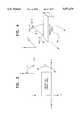
- FIG. 6is a front view of an integrated optical pitch, yaw and roll detector in accordance with a first exemplary embodiment of the present invention.
- FIG. 7is a graphical representation of the function for determining the roll angle from a quad roll detector according to the present invention.
- FIG. 8is a front view of an integrated optical pitch, yaw and roll detector according to a second exemplary embodiment of the present invention.
- FIGS. 9 and 10are schematic diagrams of the remote unit in accordance with the present invention.
- FIG. 11is a schematic diagram of the base unit in accordance with the present invention.
- FIG. 12is a timing diagram illustrating the generation and transmission of pulse packets for pitch and yaw, and roll data.
- FIG. 13is a block diagram of a remote unit in accordance with an alternative embodiment of the present invention.
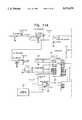
- FIG. 14is a block diagram of a system for optically rotating an icon on a screen by detecting roll of the remote unit.
- FIG. 1shows the general configuration of a fixed base unit and a movable remote unit in an optical pointing system 10, useful in interactive television or computer system.
- the base unit 12has a light beam source in the form of one (or several closely arranged) infrared LED 14 and a photodetector 16, and is positioned adjacent a television or computer screen 18 on which the position of a cursor is to be remotely controlled.
- a cursor control circuit 19is also part of the base unit, for controlling the position of a cursor on the TV or computer screen.
- the remote unit 20includes a photodetector 22 and an LED 24.
- the photodetector 22is responsive to light emitted by the LED 14 and the pointing orientation of the remote unit is determined by the relative orientation of the photodetector 22 relative to the LED 14. Signals related to the orientation of the remote unit 14 are transmitted back to the base unit 12, either optically via the LED 24, or through a hardwire connection represented in phantom at 26.
- FIG. 2shows a virtual reality system 30 having an LED light source 32 comprising a single LED or an array of LED's, closely positioned so as to serve as a single light beam source, and a photodetector 34.
- a remote unit 36which is similar to the remote unit 20 comprises a photodetector 38 and an LED 40.
- the remote unit 36 in the system configuration shown in FIG. 2is used for real-time visual display tracking.
- the LED (or array of LED's) 32emit light which is detected by the photodetector 38.
- the photodetector 38generates pointing position signals which are transmitted either optically via the LED 40 to the photodetector 34, or via a hardwire connection 42.
- the cable 42will be preferred because of the much higher speed at which the pointing position signals can be transmitted over the cable. Indeed, most virtual reality systems have cable interconnections for remote head tracking devices. Therefore, the remote unit would be provided with a simple cable plug 44, which would mate with the cable 42.
- the remote units shown in FIGS. 1 and 2could be hand-held devices or head mounted devices.
- FIGS. 3 and 4illustrate the geometry of the pointing orientation of the remote unit.
- the movement of the face of the remote upwards and downwardsis the pitch ⁇ of the remote; side-to-side movement determines the yaw ⁇ of the remote; and rotational movement of the remote determines the roll ⁇ .
- pitch and yaware determined by measuring the angle of incidence of a point source reference beam with respect to a sensor optical axis.
- the angular projections in the pitch and yaw directionsare determined by measuring the projected light distances in each axis and transforming them to angular measurements by scaling with a lens constant:
- the measured pitch and yaware most accurate for a roll angle of 0°. That is, the pitch and yaw information when the remote is at zero roll angle (perfectly aligned with the x-axis) is sufficient to precisely control the position of a cursor. However, if the remote is rotated then pitch and yaw alone cannot precisely move a cursor or follow the tracking of the remote unit. The addition of the roll component of orientation affords correction to the pitch and yaw information to provide more accurate values when the remote is not a zero roll angle.
- the equations for pitch and yaw, corrected by the roll angleare:
- ⁇x ⁇ l cos( ⁇ )-Y ⁇ l ⁇ sin( ⁇ ), where ⁇ is the detected roll angle.
- polarized lightis used to determine the roll angle of the remote unit with respect to the base unit.
- the roll angleis ultimately used to correct the pitch and yaw measurements, according to the equations above, so that very precise tracking of the remote unit can be made, to effect accurate cursor control in the application of interactive television, or accurate visual display tracking in the application of virtual reality systems.
- the roll anglemay be used for rotating icons in a graphical user interface on a computer or televisions screen. This is explained in greater detail in conjunction with FIG. 14.
- FIG. 5Aillustrates a simple polarization emitter and detector configuration comprising a fixed polarization source and four uniformly illuminated polarization responsive sensors.
- the "polarized" nature of the emitter or detectormay be achieved by placing a polarized plastic film in front of the detector or emitter. Alternatively, a polarized film may be deposited on the detector or emitter.
- FIG. 5Bshows a single polarized detector in the remote unit, and four polarized emitters at 0°, +90°, +45° and -45° in the base unit.
- FIG. 5Cshows a third configuration including two polarized detectors in the remote unit (0° and +45°) and two polarized emitters (0° and 90°) in the base unit.
- FIG. 6illustrates an integrated pitch, yaw and roll detector 50 according to the present invention.
- the integrated detector 50comprises a square aperture 52 which projects a square light spot onto a photodetector surface 54.
- the photodetector surfacecomprises four polarized detectors in an inner quad 56 which are always fully illuminated, and four unpolarized detectors in an outer quad 58 which receive light proportional to the incident angle of radiation (pointing angle).
- the projected light spotis shown at 60.
- the X and Y components of the light spot on the photodetector surface 52are calculated from intensities Q1-Q4 of the outer quad using the equations:
- the roll angleis computed using the inner quadrant intensities I 0 , I 90 , I +45 , I -45 .
- a mathematical algorithm for determining the roll angleis:
- FIG. 7illustrates the graph of the overall function.
- the computations of the corrected pitch and yaw anglesmay be performed in the base unit 12, but can alternatively be performed in the host computer (virtual reality system), or in the remote unit if it has adequate computational capabilities. If the remote unit is to perform the computations, it would include a microprocessor chip or other computing chip to perform such computations.
- the remote unitdetects values for Q1-Q4, and I 0 , I +45 , I -45 , and I 90 , and transmits these values to the base unit which processes them to ultimately determine the corrected pitch and yaw angles, and to thereby move the position of the cursor in the case of an interactive television system, or adjust the visual display tracking in the case of a virtual reality system.
- the pitch, yaw and roll valuescan be computed in the remote unit using the same algorithm, and therefore only the computed pitch, yaw and roll data need to be transmitted to the base unit or host computer.
- roll detectionmay be achieved with a single emitter in the base unit and only two polarized detectors in the remote unit instead of two quadrature pairs.
- FIG. 8illustrates this other integrated photodetector. The reason for using two quadrature pairs is to eliminate the need to know the 0° polarization intensity. This can be calculated from the unpolarized light intensities detected by the unpolarized pitch and detectors.
- the remote polarized detectorswould be oriented at 0° and 45° and the base polarized emitter oriented at 0° to allow sensing over the same +/-90° range.
- the total light intensity incident on the detectoris proportional to the aperture area (A a ),
- FIGS. 9 and 10illustrate the electronics of the remote unit.
- the measurements made by the roll detector 56 and pitch and yaw detector 58are transmitted to the base unit by a series of pulses, the spacing between which represent the values of Q1-Q4 and I 0 , I +45 , I -45 , and I 90 .
- the information reporting technique for the pitch and yaw information disclosed in the prior applicationis used in the same manner for transmitting the pitch, yaw and roll information in accordance with the present invention.
- the detectors 56 and 58are connected to switches 70 and 72, respectively, which are operated to alternately connect the data Q1-Q4 and I 0 , I +45 , I -45 , and I 90 , to the data input pins of the state machine interface chip 73.
- Chip 73processes the data, performs automatic gain control and generates an AMIC OUTPUT at the VFO pin.
- more than one group of pitch, yaw and roll datamay be processed by each of several interface chips, though only one interface chip 73 is shown for simplicity. Consequently, it may be necessary to interleave transmission of data from each chip to the base unit.
- one of several connectors 74, 76 and 78connects microprocessor 80 to one of several state machine interface chips.
- the microprocessor chip 80reads the output from each interface chip (one interface chip at a time) and generates a series of pulses for the data associated with each interface chip, the time spacing between consecutive pulses representing the photodetector data, either Q1-Q4 or I 0 , I +45 , I -45 , and I 90 .
- the series of pulsesconsists of packets which are separated in time to allow for identification of each packet.
- a packetwill consists of a series of pulses which represent Q1-Q4 or I 0 , I +45 , I -45 , and I 90 .
- one packetrepresents pitch and yaw data, and another packet will represent roll data.
- a proper protocolcan be established, using techniques well known in the art, to separate and identify each of the packets at the base unit.
- the pulse packetsmay be transmitted to the base unit by a hardwire connection, via an RS232 output terminal 82, or the packets may be transmitted wirelessly through a driver 84 and LED 86, as disclosed, in U.S. Pat. No. 5,045,843.
- FIG. 11illustrates the electronic circuitry of the base unit 12.
- the base unit 12is controlled by a microprocessor 90, and receives data either through an RS232 input terminal 92 or via a photodetector 94.
- the time spacing between the series of pulsesis interpreted by the microprocessor to reconstruct the values of Q1-Q4 and I 0 , I +45 , I -45 , and I 90 . This is described in the pending patent application mentioned above.
- the microprocessor 90ultimately determines the corrected pitch and yaw of the remote unit, according to the mathematical equations described above.
- the base unit 12also includes several LED's 96 which together serve to define a single light source.
- a polarizer 98is placed over the LED's so as to generate, for example, horizontally polarized light, which is transmitted towards the remote unit and impinges on the photodetector 50.
- the pitch and yaw datais supplied to an associated television or virtual reality system via an RS232 output terminal 100.
- FIG. 12illustrates the timing and generation of the pitch and yaw pulse packet and roll pulse packet.
- the chip 73can process data from one detector at a time. Therefore, the samples from, for example, the pitch and yaw detector 58 are selected first and are gated onto output channels OC0-OC3, together with a Range value representative of an automatic gain control level. The chip 73 then generates a series of pulses on the VFO pin (called AMIC OUTPUT in FIG. 9, labelled V/F Out in FIG. 12), the spacing between the pulses representing the values of the signals Q1-Q4.
- This first series of pulsesdefines the pitch and yaw pulse packet.
- samples from the roll Detector 56are gated onto the output channels OC0-OC3 and are ultimately converted into a series of pulses, the spacing between which represents the values of I 0 , I +45 , I -45 , and I 90 .
- a predetermined time delay or protocolmay be provided between the two packets so that the base unit can determine when one packet ends and the next packet begins, and can also identify the data of each packet, pitch and yaw, or roll.
- pitch and yaw data and roll datacould be transmitted to the base unit by other means, either optically or via hardwire.
- the foregoingis only an example of one way to consolidate the data and optically transmit it.
- power consumptionis greatly reduced in the remote unit. This is important where the remote unit is wireless and battery operated.
- FIG. 13illustrates a block diagram of a remote unit according to another embodiment of the present invention.
- this embodimentthere are multiple integrated detectors, each positioned and therefore assigned to a particular yaw angle.
- this type of remote unitmay be designed for hardwire connection, and the data is transmitted to the base unit digitally.
- the integrated detectorsmay be assigned to particular orientations.
- one detector 200is positioned on the face of the remote at 0° yaw; one detector 202 is positioned on a side of the remote at -90° yaw; and another detector 204 is positioned on the opposite side of the remote at 90° yaw.
- each detectorhas a quad pitch and yaw detector and a quad roll detector, similar to detector 50 shown in FIG. 6. Consequently, each detector outputs pitch and yaw data Q1-Q4 and roll data, referred to here as P1-P4.
- a bank of switches 206gate the pitch, yaw and roll data to a four signal select switch 208. Only the four component pitch and yaw data or four component roll data is processed at once. Switch 208 selects in sequence the pitch and yaw data, then the roll data from each detector. This data is amplified by pre-amp 210 and then amplified again in an automatic gain control loop 212. Ultimately, the data, which is in analog form up to now, is converted to a 10-bit digital form by the 10 bit A/D converter 214. The 10-bit output D0-D9 of the A/D converter 214 is supplied to the state machine controller 216.
- the remote unit of FIG. 13converts the analog pitch, yaw and roll data to digital form almost immediately before it is transmitted to the base unit.
- the state machine controller 216generates digital serial output pulses which represent the analog pitch and yaw data, or roll data.
- the digital signalsare more easily transmitted at higher rates over the hardwire line to the base unit, and thus is a preferred method when the remote is to be hardwired to the base unit. This is particularly advantageous in virtual reality systems, where it is necessary to transmit new visual display tracking data very fast, for accurate real-time virtual reality display.
- the functionality of the base unitmay be incorporated into a virtual reality system.
- the roll informationmay be used to rotate an icon or other graphical representation of an object in a graphical user interface on a computer or television screen.
- the rotation or roll of the remote unitis used to cause the icon or object, such as a knob icon, to rotate on the screen.
- FIG. 14illustrates a remote unit 20, a base unit 12 and a display screen 250, such as a computer display screen or television screen.
- a computer generated icon or objectsuch as a knob, is shown at 260 on the screen 250. It may be desirable in certain instances, to rotate the knob 260. For example, in controlling a parameter on a television, such as volume.
- the remote unit 20is pointed at the volume knob icon 260 to position the cursor 270 on the icon 260.
- a single "click" of a select button 290 on the remotefrees the icon to rotate (arrow 280), with the degree of rotation being proportional to the roll angle of the remote unit 20.
- This interactionmay be achieved in the familiar "click and drag" fashion used with a conventional hard-wired mouse, to allow the icon rotation to occur while the select button 290 is kept depressed. Alternatively, the icon may remain free to rotate until another button press "drops" it.
- the roll information transmitted to the base unit 12is processed similar to the pitch and yaw information by the cursor control circuit 19. It is to be understood that software interfaces may also assist in the display of various icons, and movement of the cursor with respect to those icons.
- the roll informationmay be determined by the polarized emitter-detector configurations described in the foregoing, in which the remote unit transmits the roll information back to the a base unit.
- the remote unittransmits polarized light to a polarized detector on a base unit which can receive light to determine the roll of the remote unit relative to the base unit, without the need for the base unit to transmit light to the remote unit.
Landscapes
- Engineering & Computer Science (AREA)
- General Engineering & Computer Science (AREA)
- Theoretical Computer Science (AREA)
- Human Computer Interaction (AREA)
- Physics & Mathematics (AREA)
- General Physics & Mathematics (AREA)
- Position Input By Displaying (AREA)
Abstract
Description
Φ=Y·l cos(Ω)+x·l·sin(Ω)
X=(Q1+Q4-Q2-Q3)/(Q1+Q2+Q3+Q4)
Y=(Q1+Q2-Q3-Q4)/(Q1+Q2+Q3+Q4).
I.sub.t =k·A.sub.a.
I.sub.0 =I.sub.t ·A.sub.p /A.sub.a ·cos.sup.2 (Ω.sub.0)=k·A.sub.p ·cos.sup.2 (Ω.sub.0),
I.sub.+45 =k·A.sub.p ·cos.sup.2 (Ω.sub.+45),
Ω.sub.0 =+/-cos.sup.-1 {(A.sub.a -2A.sub.p)/A.sub.p ·I.sub.0 /ΣI.sub.q }.sup.1/2,Ω.sub.+45 =+/-cos.sup.-1 {(A.sub.a -2A.sub.p)/A.sub.p ·I.sub.+45 /ΣI.sub.q }.sup.1/2.Claims (24)
Priority Applications (3)
| Application Number | Priority Date | Filing Date | Title |
|---|---|---|---|
| US08/178,557US5574479A (en) | 1994-01-07 | 1994-01-07 | Optical system for determining the roll orientation of a remote unit relative to a base unit |
| PCT/US1995/000250WO1995019031A1 (en) | 1994-01-07 | 1995-01-09 | System for determining the roll of a remote unit |
| AU15252/95AAU1525295A (en) | 1994-01-07 | 1995-01-09 | System for determining the roll of a remote unit |
Applications Claiming Priority (1)
| Application Number | Priority Date | Filing Date | Title |
|---|---|---|---|
| US08/178,557US5574479A (en) | 1994-01-07 | 1994-01-07 | Optical system for determining the roll orientation of a remote unit relative to a base unit |
Publications (1)
| Publication Number | Publication Date |
|---|---|
| US5574479Atrue US5574479A (en) | 1996-11-12 |
Family
ID=22653008
Family Applications (1)
| Application Number | Title | Priority Date | Filing Date |
|---|---|---|---|
| US08/178,557Expired - Fee RelatedUS5574479A (en) | 1994-01-07 | 1994-01-07 | Optical system for determining the roll orientation of a remote unit relative to a base unit |
Country Status (3)
| Country | Link |
|---|---|
| US (1) | US5574479A (en) |
| AU (1) | AU1525295A (en) |
| WO (1) | WO1995019031A1 (en) |
Cited By (117)
| Publication number | Priority date | Publication date | Assignee | Title |
|---|---|---|---|---|
| US5737401A (en)* | 1996-06-14 | 1998-04-07 | Quadrum Telecommunications, Inc. | Full coin box signalling device for use with coin telephones |
| FR2758639A1 (en)* | 1997-01-17 | 1998-07-24 | Samsung Electronics Co Ltd | METHOD FOR TRANSMITTING POINTING DATA FROM A REMOTE CONTROL AND METHOD FOR PROCESSING DATA RECEIVED |
| US5786804A (en)* | 1995-10-06 | 1998-07-28 | Hewlett-Packard Company | Method and system for tracking attitude |
| US5796387A (en)* | 1994-08-16 | 1998-08-18 | Smith Engineering | Positioning system using infrared radiation |
| US5892501A (en)* | 1996-01-17 | 1999-04-06 | Lg Electronics Inc, | Three dimensional wireless pointing device |
| US5943476A (en)* | 1996-06-13 | 1999-08-24 | August Design, Inc. | Method and apparatus for remotely sensing orientation and position of objects |
| US5999167A (en)* | 1996-11-08 | 1999-12-07 | Stephen A. Marsh | Cursor control device |
| WO2001003296A1 (en)* | 1999-07-02 | 2001-01-11 | Vlg Virtual Laser Systems Gmbh | Interactive control and input system for electronic appliances |
| US6344846B1 (en) | 1997-10-27 | 2002-02-05 | Stephen P. Hines | Optical retroreflective remote control |
| WO2001091042A3 (en)* | 2000-05-24 | 2002-06-27 | Infineon Technologies Ag | Positioning unit |
| US6417839B1 (en) | 1999-05-20 | 2002-07-09 | Ascension Technology Corporation | System for position and orientation determination of a point in space using scanning laser beams |
| US6424335B1 (en)* | 1998-09-02 | 2002-07-23 | Fujitsu Limited | Notebook computer with detachable infrared multi-mode input device |
| US6424410B1 (en)* | 1999-08-27 | 2002-07-23 | Maui Innovative Peripherals, Inc. | 3D navigation system using complementary head-mounted and stationary infrared beam detection units |
| US6486873B1 (en) | 2000-04-06 | 2002-11-26 | Microsoft Corporation | Illuminated computer input device |
| US6608688B1 (en)* | 1998-04-03 | 2003-08-19 | Image Guided Technologies, Inc. | Wireless optical instrument for position measurement and method of use therefor |
| KR20030078312A (en)* | 2002-03-29 | 2003-10-08 | 김주석 | System and Method for controlling a mouse using a remote controller |
| US6636199B2 (en)* | 2000-04-07 | 2003-10-21 | Canon Kabushiki Kaisha | Coordinate input apparatus and method, coordinate input pointing device, storage medium, and computer program |
| KR20040033712A (en)* | 2002-10-15 | 2004-04-28 | 삼은전자 주식회사 | Mouse embedded remote control receiver |
| WO2004041381A3 (en)* | 2002-11-04 | 2004-09-16 | Levitation Technologies Ltd | Control systems for use with flying craft and other remote elements |
| US20040201595A1 (en)* | 2003-04-11 | 2004-10-14 | Microsoft Corporation | Self-orienting display |
| US20050179662A1 (en)* | 1995-10-06 | 2005-08-18 | Agilent Technologies, Inc. | "Seeing eye" mouse for a computer system |
| US6970651B1 (en) | 2001-07-31 | 2005-11-29 | Terabeam Corporation | High-sensitivity tracking in free-space optical communication systems |
| US20060114119A1 (en)* | 2004-11-30 | 2006-06-01 | Sharp Kabushiki Kaisha | Remote control device and display device |
| US20060120726A1 (en)* | 2004-11-30 | 2006-06-08 | Sharp Kabushiki Kaisha | Remote control device and display device |
| US20060152489A1 (en)* | 2005-01-12 | 2006-07-13 | John Sweetser | Handheld vision based absolute pointing system |
| US7102616B1 (en)* | 1999-03-05 | 2006-09-05 | Microsoft Corporation | Remote control device with pointing capacity |
| US7124676B1 (en)* | 2005-06-07 | 2006-10-24 | Princeton Scientific Instruments | Muzzle reference system |
| US20070018950A1 (en)* | 2005-06-24 | 2007-01-25 | Nintendo Co., Ltd. | Input data processing program and input data processing apparatus |
| US20070060383A1 (en)* | 2005-09-14 | 2007-03-15 | Nintendo Co., Ltd. | Video game program and video game system |
| US20070072674A1 (en)* | 2005-09-12 | 2007-03-29 | Nintendo Co., Ltd. | Information processing program |
| US20070178974A1 (en)* | 1999-10-04 | 2007-08-02 | Nintendo Co., Ltd. | Game system and game information storage medium used for same |
| US20070191112A1 (en)* | 2006-02-07 | 2007-08-16 | Nintendo Co., Ltd. | Storage medium storing subject selecting program and subject selecting apparatus |
| US20070213128A1 (en)* | 2006-03-09 | 2007-09-13 | Nintendo Co., Ltd. | Video game device and storage medium storing video game program |
| US20070213109A1 (en)* | 2006-03-13 | 2007-09-13 | Nintendo Co., Ltd. | Game apparatus and storage medium having game program stored thereon |
| US20070211025A1 (en)* | 2006-03-08 | 2007-09-13 | Nintendo Co., Ltd. | Motion determining apparatus and storage medium having motion determining program stored thereon |
| US20070211026A1 (en)* | 2006-03-09 | 2007-09-13 | Nintendo Co., Ltd. | Coordinate calculating apparatus and coordinate calculating program |
| US20070211027A1 (en)* | 2006-03-09 | 2007-09-13 | Nintendo Co., Ltd. | Image processing apparatus and storage medium storing image processing program |
| US20070222750A1 (en)* | 2006-03-23 | 2007-09-27 | Nintendo Co., Ltd., | Position calculation apparatus, storage medium storing position calculation program, game apparatus, and storage medium storing game program |
| US20070242041A1 (en)* | 2006-04-12 | 2007-10-18 | Nintendo Co. Ltd. | Character input program and character input device |
| US20070243931A1 (en)* | 2006-04-14 | 2007-10-18 | Nintendo Co., Ltd. | Game apparatus and game program |
| US20070257940A1 (en)* | 2006-05-02 | 2007-11-08 | Nintendo Co., Ltd. | Storage medium storing game image processing program, game image processing apparatus and game image processing method |
| US20080051197A1 (en)* | 2006-08-15 | 2008-02-28 | Mark Jawad | Systems and methods for reducing jitter associated with a control device |
| US20080052750A1 (en)* | 2006-08-28 | 2008-02-28 | Anders Grunnet-Jepsen | Direct-point on-demand information exchanges |
| US20080064498A1 (en)* | 2006-09-13 | 2008-03-13 | Nintendo Co., Ltd. | Storage medium storing a game program, game apparatus, and game controlling method |
| US20080096660A1 (en)* | 2006-10-19 | 2008-04-24 | Nintendo Co., Ltd. | Storage medium storing a game program, game apparatus, and game control method |
| US20080119270A1 (en)* | 2006-11-16 | 2008-05-22 | Nintendo Co., Ltd. | Game apparatus and storage medium having game program stored thereon |
| US20080125223A1 (en)* | 2006-11-29 | 2008-05-29 | Nintendo Co., Ltd. | Information processing apparatus and storage medium storing information processing program |
| US20080158436A1 (en)* | 2006-12-28 | 2008-07-03 | Pixart Imaging Inc. | Cursor control method and apparatus |
| US20080174702A1 (en)* | 2007-01-23 | 2008-07-24 | Pixart Imaging Inc. | Quasi analog knob control method and appartus using the same |
| US20080180395A1 (en)* | 2005-03-04 | 2008-07-31 | Gray Robert H | Computer pointing input device |
| US20080215288A1 (en)* | 2006-03-22 | 2008-09-04 | Nintendo Co., Ltd. | Inclination calculation apparatus and inclination calculation program, and game apparatus and game program |
| US20080287189A1 (en)* | 2007-05-09 | 2008-11-20 | Nintendo Of America Inc. | System and method for using accelerometer outputs to control an object rotating on a display |
| US20080293492A1 (en)* | 2007-05-09 | 2008-11-27 | Nintendo Co., Ltd. | Handheld control device for a processor-controlled system |
| US20080291163A1 (en)* | 2004-04-30 | 2008-11-27 | Hillcrest Laboratories, Inc. | 3D Pointing Devices with Orientation Compensation and Improved Usability |
| US20080291160A1 (en)* | 2007-05-09 | 2008-11-27 | Nintendo Co., Ltd. | System and method for recognizing multi-axis gestures based on handheld controller accelerometer outputs |
| US20080316103A1 (en)* | 2007-06-22 | 2008-12-25 | Broadcom Corporation | Apparatus for position detection using multiple antennas |
| US20080318677A1 (en)* | 2007-06-20 | 2008-12-25 | Nintendo Co., Ltd. | Storage medium having information processing program stored thereon and information processing apparatus |
| US20080317441A1 (en)* | 2003-03-06 | 2008-12-25 | Microsoft Corporation | Systems and methods for receiving, storing, and rendering digital video, music, and pictures on a personal media player |
| US20090093304A1 (en)* | 2007-10-09 | 2009-04-09 | Nintendo Co., Ltd. | Computer readable storage medium having a game program stored thereon and a game apparatus |
| US20090128815A1 (en)* | 2006-03-15 | 2009-05-21 | Koninklijke Philips Electronics N.V. | Remote control pointing technology with roll detection |
| US20090144020A1 (en)* | 2007-11-30 | 2009-06-04 | Keizo Ohta | Storage medium having step count calculation program stored therein, step count calculation apparatus, and step count calculation system |
| US20090149257A1 (en)* | 2004-07-29 | 2009-06-11 | Motiva Llc | Human movement measurement system |
| US20090187371A1 (en)* | 2008-01-21 | 2009-07-23 | Nintendo Co., Ltd. | Storage medium storing information processing program and information processing apparatus |
| US7596466B2 (en) | 2006-03-28 | 2009-09-29 | Nintendo Co., Ltd. | Inclination calculation apparatus and inclination calculation program, and game apparatus and game program |
| US20090254274A1 (en)* | 2007-07-27 | 2009-10-08 | Kulik Victor | Navigation system for providing celestial and terrestrial information |
| US20090281765A1 (en)* | 2008-05-09 | 2009-11-12 | Shrenik Deliwala | Method of locating an object in 3d |
| US20090279107A1 (en)* | 2008-05-09 | 2009-11-12 | Analog Devices, Inc. | Optical distance measurement by triangulation of an active transponder |
| US20090326847A1 (en)* | 2008-06-30 | 2009-12-31 | Nintendo Co., Ltd. | Orientation calculation apparatus, storage medium having orientation calculation program stored therein, game apparatus, and storage medium having game program stored therein |
| US20100010772A1 (en)* | 2008-07-10 | 2010-01-14 | Kenta Sato | Computer readable recording medium recording information processing program and information processing apparatus |
| US20100053467A1 (en)* | 2008-08-31 | 2010-03-04 | Maxson Brian D | Rotation sensitive remote control using polarized light |
| US20100060575A1 (en)* | 2008-09-05 | 2010-03-11 | Keizo Ohta | Computer readable recording medium recording image processing program and image processing apparatus |
| US20100094585A1 (en)* | 2006-11-07 | 2010-04-15 | Apple Inc. | Remote control systems that can distinguish stray light sources |
| US7716008B2 (en) | 2007-01-19 | 2010-05-11 | Nintendo Co., Ltd. | Acceleration data processing program, and storage medium, and acceleration data processing apparatus for use with the same |
| US7774155B2 (en) | 2006-03-10 | 2010-08-10 | Nintendo Co., Ltd. | Accelerometer-based controller |
| US7786976B2 (en) | 2006-03-09 | 2010-08-31 | Nintendo Co., Ltd. | Coordinate calculating apparatus and coordinate calculating program |
| US20100220002A1 (en)* | 2009-03-02 | 2010-09-02 | Omnitek Partners Llc | System and Method For Roll Angle Indication and Measurement in Flying Objects |
| US20100231513A1 (en)* | 2008-12-03 | 2010-09-16 | Analog Devices, Inc. | Position measurement systems using position sensitive detectors |
| US20100305418A1 (en)* | 2009-05-27 | 2010-12-02 | Shrenik Deliwala | Multiuse optical sensor |
| US7850527B2 (en) | 2000-02-22 | 2010-12-14 | Creative Kingdoms, Llc | Magic-themed adventure game |
| RU2410722C1 (en)* | 2009-06-08 | 2011-01-27 | Федеральное Государственное Унитарное Предприятие "Государственный Рязанский Приборный Завод" | Teleorientation laser system having optical feedback channel (versions) |
| US7896742B2 (en) | 2000-02-22 | 2011-03-01 | Creative Kingdoms, Llc | Apparatus and methods for providing interactive entertainment |
| US7927216B2 (en) | 2005-09-15 | 2011-04-19 | Nintendo Co., Ltd. | Video game system with wireless modular handheld controller |
| US7931535B2 (en) | 2005-08-22 | 2011-04-26 | Nintendo Co., Ltd. | Game operating device |
| US7942745B2 (en) | 2005-08-22 | 2011-05-17 | Nintendo Co., Ltd. | Game operating device |
| US20110212777A1 (en)* | 2008-04-17 | 2011-09-01 | Power Digital Communications Co., Ltd. | Game device enabling three-dimensional movement |
| US8013840B1 (en) | 2000-04-06 | 2011-09-06 | Microsoft Corporation | User notification system with an illuminated computer input device |
| US8089458B2 (en) | 2000-02-22 | 2012-01-03 | Creative Kingdoms, Llc | Toy devices and methods for providing an interactive play experience |
| US20120154268A1 (en)* | 2007-05-14 | 2012-06-21 | Apple Inc. | Remote control systems that can distinguish stray light sources |
| US8226493B2 (en) | 2002-08-01 | 2012-07-24 | Creative Kingdoms, Llc | Interactive play devices for water play attractions |
| US8267786B2 (en) | 2005-08-24 | 2012-09-18 | Nintendo Co., Ltd. | Game controller and game system |
| US8308563B2 (en) | 2005-08-30 | 2012-11-13 | Nintendo Co., Ltd. | Game system and storage medium having game program stored thereon |
| US8313379B2 (en) | 2005-08-22 | 2012-11-20 | Nintendo Co., Ltd. | Video game system with wireless modular handheld controller |
| US8409003B2 (en) | 2005-08-24 | 2013-04-02 | Nintendo Co., Ltd. | Game controller and game system |
| US8608535B2 (en) | 2002-04-05 | 2013-12-17 | Mq Gaming, Llc | Systems and methods for providing an interactive game |
| US8629836B2 (en) | 2004-04-30 | 2014-01-14 | Hillcrest Laboratories, Inc. | 3D pointing devices with orientation compensation and improved usability |
| US8702515B2 (en) | 2002-04-05 | 2014-04-22 | Mq Gaming, Llc | Multi-platform gaming system using RFID-tagged toys |
| US8723803B2 (en) | 2004-05-28 | 2014-05-13 | Ultimatepointer, Llc | Easily deployable interactive direct-pointing system and presentation control system and calibration method therefor |
| US8753165B2 (en) | 2000-10-20 | 2014-06-17 | Mq Gaming, Llc | Wireless toy systems and methods for interactive entertainment |
| US8758136B2 (en) | 1999-02-26 | 2014-06-24 | Mq Gaming, Llc | Multi-platform gaming systems and methods |
| US8913003B2 (en) | 2006-07-17 | 2014-12-16 | Thinkoptics, Inc. | Free-space multi-dimensional absolute pointer using a projection marker system |
| RU2537662C1 (en)* | 2013-08-23 | 2015-01-10 | Открытое акционерное общество "Государственный Рязанский приборный завод" | Method of teleorientation of moving objects |
| US9176598B2 (en) | 2007-05-08 | 2015-11-03 | Thinkoptics, Inc. | Free-space multi-dimensional absolute pointer with improved performance |
| US9261978B2 (en) | 2004-04-30 | 2016-02-16 | Hillcrest Laboratories, Inc. | 3D pointing devices and methods |
| US9285897B2 (en) | 2005-07-13 | 2016-03-15 | Ultimate Pointer, L.L.C. | Easily deployable interactive direct-pointing system and calibration method therefor |
| US9341697B2 (en) | 2012-06-25 | 2016-05-17 | Teledyne Scientific & Imaging, Llc | Moving platform orientation tracking system |
| US9364755B1 (en)* | 2006-05-08 | 2016-06-14 | Nintendo Co., Ltd. | Methods and apparatus for using illumination marks for spatial pointing |
| US20160223365A1 (en)* | 2014-02-04 | 2016-08-04 | Teledyne Scientific & Imaging, Llc | Moving platform roll sensor system |
| US9446319B2 (en) | 2003-03-25 | 2016-09-20 | Mq Gaming, Llc | Interactive gaming toy |
| WO2017007637A1 (en)* | 2015-07-07 | 2017-01-12 | Google Inc. | System for tracking a handheld device in virtual reality |
| US9702690B2 (en) | 2011-12-19 | 2017-07-11 | Analog Devices, Inc. | Lens-less optical position measuring sensor |
| US9720556B2 (en) | 2007-10-01 | 2017-08-01 | Nintendo Co., Ltd. | Storage medium storing image processing program and image processing apparatus |
| US9739571B2 (en) | 2015-01-06 | 2017-08-22 | Teledyne Scientific & Imaging, Llc | Moving object command link system and method |
| US20170244811A1 (en)* | 2016-02-22 | 2017-08-24 | Google Inc. | Device pairing in augmented / virtual reality environment |
| US10159897B2 (en) | 2004-11-23 | 2018-12-25 | Idhl Holdings, Inc. | Semantic gaming and application transformation |
| US10892832B2 (en) | 2014-11-11 | 2021-01-12 | Teledyne Scientific & Imaging, Llc | Moving platform roll angle determination system using RF communications link |
| US11060819B2 (en) | 2019-05-23 | 2021-07-13 | General Dynamics Mission Systems—Canada | Armored vehicle, method, and weapon measurement system for determining barrel elevation |
| US11674797B2 (en) | 2020-03-22 | 2023-06-13 | Analog Devices, Inc. | Self-aligned light angle sensor using thin metal silicide anodes |
Families Citing this family (10)
| Publication number | Priority date | Publication date | Assignee | Title |
|---|---|---|---|---|
| IT1304963B1 (en)* | 1996-10-17 | 2001-04-05 | Alessandro Mongarli | AIMING DEVICE FOR AN ELECTRONIC PROCESSOR |
| US6990639B2 (en) | 2002-02-07 | 2006-01-24 | Microsoft Corporation | System and process for controlling electronic components in a ubiquitous computing environment using multimodal integration |
| US8456534B2 (en) | 2004-10-25 | 2013-06-04 | I-Interactive Llc | Multi-directional remote control system and method |
| JP5231809B2 (en)* | 2005-01-12 | 2013-07-10 | スィンクオプティクス インコーポレイテッド | Handheld vision type absolute pointing system |
| BRPI0817191B1 (en)* | 2007-09-26 | 2022-04-19 | Interdigital Ce Patent Holdings | Method of providing spin compensation in a control device and control device |
| US9298287B2 (en) | 2011-03-31 | 2016-03-29 | Microsoft Technology Licensing, Llc | Combined activation for natural user interface systems |
| US9842168B2 (en) | 2011-03-31 | 2017-12-12 | Microsoft Technology Licensing, Llc | Task driven user intents |
| US9760566B2 (en) | 2011-03-31 | 2017-09-12 | Microsoft Technology Licensing, Llc | Augmented conversational understanding agent to identify conversation context between two humans and taking an agent action thereof |
| US9064006B2 (en) | 2012-08-23 | 2015-06-23 | Microsoft Technology Licensing, Llc | Translating natural language utterances to keyword search queries |
| US9170435B2 (en)* | 2013-03-12 | 2015-10-27 | Ge Aviation Systems Llc | Method of forming a grid defining a first relative reference frame |
Citations (40)
| Publication number | Priority date | Publication date | Assignee | Title |
|---|---|---|---|---|
| US3306159A (en)* | 1963-06-19 | 1967-02-28 | North American Aviation Inc | Angle transducer employing polarized light |
| US3678283A (en)* | 1970-10-22 | 1972-07-18 | Us Navy | Radiation sensitive optical tracker |
| US3706493A (en)* | 1969-12-30 | 1972-12-19 | Itt | Ranging and aiming system |
| US3707434A (en)* | 1970-11-30 | 1972-12-26 | Federal Huber Co | Rigidified resinous laminate |
| US3727055A (en)* | 1970-09-24 | 1973-04-10 | Gen Electric | Optical positioning system |
| US3778163A (en)* | 1969-04-30 | 1973-12-11 | Hughes Aircraft Co | Rotation-rate measuring apparatus |
| US3867629A (en)* | 1974-05-28 | 1975-02-18 | Us Navy | System for measuring rotation using polarized light |
| US4123165A (en)* | 1977-05-31 | 1978-10-31 | The United States Of America As Represented By The Secretary Of The Army | Attitude determination using two color, dual-sweeping laser system |
| US4209255A (en)* | 1979-03-30 | 1980-06-24 | United Technologies Corporation | Single source aiming point locator |
| US4320462A (en)* | 1980-03-31 | 1982-03-16 | Hughes Aircraft Company | High speed laser pulse analyzer |
| US4396945A (en)* | 1981-08-19 | 1983-08-02 | Solid Photography Inc. | Method of sensing the position and orientation of elements in space |
| US4506354A (en)* | 1982-09-30 | 1985-03-19 | Position Orientation Systems, Ltd. | Ultrasonic position detecting system |
| US4560272A (en)* | 1980-12-10 | 1985-12-24 | The Perkin-Elmer Corporation | Three-axis angle sensor |
| US4565999A (en)* | 1983-04-01 | 1986-01-21 | Prime Computer, Inc. | Light pencil |
| US4576481A (en)* | 1982-12-13 | 1986-03-18 | Position Orientation Systems, Ltd. | Passive optical position measurement system |
| US4622644A (en)* | 1984-05-10 | 1986-11-11 | Position Orientation Systems, Ltd. | Magnetic position and orientation measurement system |
| US4626892A (en)* | 1984-03-05 | 1986-12-02 | Rca Corporation | Television system with menu like function control selection |
| US4641205A (en)* | 1984-03-05 | 1987-02-03 | Rca Corporation | Television system scheduler with on-screen menu type programming prompting apparatus |
| US4642786A (en)* | 1984-05-25 | 1987-02-10 | Position Orientation Systems, Ltd. | Method and apparatus for position and orientation measurement using a magnetic field and retransmission |
| JPS6252631A (en)* | 1985-08-31 | 1987-03-07 | Nec Home Electronics Ltd | Position input device |
| US4653102A (en)* | 1985-11-05 | 1987-03-24 | Position Orientation Systems | Directional microphone system |
| US4660981A (en)* | 1983-11-17 | 1987-04-28 | Mydata Ab | Method and apparatus for calibrating a positioning system |
| US4684249A (en)* | 1984-04-09 | 1987-08-04 | Gec Avionics Limited | Angular position sensors |
| US4701047A (en)* | 1984-06-22 | 1987-10-20 | Dornier Gmbh | Line selection for preparing range images |
| US4745402A (en)* | 1987-02-19 | 1988-05-17 | Rca Licensing Corporation | Input device for a display system using phase-encoded signals |
| US4776016A (en)* | 1985-11-21 | 1988-10-04 | Position Orientation Systems, Inc. | Voice control system |
| US4796019A (en)* | 1987-02-19 | 1989-01-03 | Rca Licensing Corporation | Input device for a display system |
| US4823170A (en)* | 1985-02-22 | 1989-04-18 | Position Orientation Systems, Ltd. | Line of sight measuring system |
| US4855725A (en)* | 1987-11-24 | 1989-08-08 | Fernandez Emilio A | Microprocessor based simulated book |
| US4858203A (en)* | 1985-09-26 | 1989-08-15 | Position Orientation Systems, Inc. | Omnidirectional distance measurement system |
| US4924216A (en)* | 1988-02-12 | 1990-05-08 | Acemore International Ltd. | Joystick controller apparatus |
| US4923303A (en)* | 1986-02-27 | 1990-05-08 | Messerschmitt-Bolkow-Blohm Gmbh | Measuring device for location and attitude determination of an object |
| US4925189A (en)* | 1989-01-13 | 1990-05-15 | Braeunig Thomas F | Body-mounted video game exercise device |
| US5045843A (en)* | 1988-12-06 | 1991-09-03 | Selectech, Ltd. | Optical pointing device |
| US5059958A (en)* | 1990-04-10 | 1991-10-22 | Jacobs Jordan S | Manually held tilt sensitive non-joystick control box |
| US5068645A (en)* | 1987-10-14 | 1991-11-26 | Wang Laboratories, Inc. | Computer input device using an orientation sensor |
| US5142506A (en)* | 1990-10-22 | 1992-08-25 | Logitech, Inc. | Ultrasonic position locating method and apparatus therefor |
| US5162781A (en)* | 1987-10-02 | 1992-11-10 | Automated Decisions, Inc. | Orientational mouse computer input system |
| US5181181A (en)* | 1990-09-27 | 1993-01-19 | Triton Technologies, Inc. | Computer apparatus input device for three-dimensional information |
| US5452413A (en)* | 1992-12-18 | 1995-09-19 | International Business Machines Corporation | Method and system for manipulating wide-angle images |
- 1994
- 1994-01-07USUS08/178,557patent/US5574479A/ennot_activeExpired - Fee Related
- 1995
- 1995-01-09AUAU15252/95Apatent/AU1525295A/ennot_activeAbandoned
- 1995-01-09WOPCT/US1995/000250patent/WO1995019031A1/enactiveApplication Filing
Patent Citations (41)
| Publication number | Priority date | Publication date | Assignee | Title |
|---|---|---|---|---|
| US3306159A (en)* | 1963-06-19 | 1967-02-28 | North American Aviation Inc | Angle transducer employing polarized light |
| US3778163A (en)* | 1969-04-30 | 1973-12-11 | Hughes Aircraft Co | Rotation-rate measuring apparatus |
| US3706493A (en)* | 1969-12-30 | 1972-12-19 | Itt | Ranging and aiming system |
| US3727055A (en)* | 1970-09-24 | 1973-04-10 | Gen Electric | Optical positioning system |
| US3678283A (en)* | 1970-10-22 | 1972-07-18 | Us Navy | Radiation sensitive optical tracker |
| US3707434A (en)* | 1970-11-30 | 1972-12-26 | Federal Huber Co | Rigidified resinous laminate |
| US3867629A (en)* | 1974-05-28 | 1975-02-18 | Us Navy | System for measuring rotation using polarized light |
| US4123165A (en)* | 1977-05-31 | 1978-10-31 | The United States Of America As Represented By The Secretary Of The Army | Attitude determination using two color, dual-sweeping laser system |
| US4209255A (en)* | 1979-03-30 | 1980-06-24 | United Technologies Corporation | Single source aiming point locator |
| US4320462A (en)* | 1980-03-31 | 1982-03-16 | Hughes Aircraft Company | High speed laser pulse analyzer |
| US4560272A (en)* | 1980-12-10 | 1985-12-24 | The Perkin-Elmer Corporation | Three-axis angle sensor |
| US4396945A (en)* | 1981-08-19 | 1983-08-02 | Solid Photography Inc. | Method of sensing the position and orientation of elements in space |
| US4506354A (en)* | 1982-09-30 | 1985-03-19 | Position Orientation Systems, Ltd. | Ultrasonic position detecting system |
| US4576481A (en)* | 1982-12-13 | 1986-03-18 | Position Orientation Systems, Ltd. | Passive optical position measurement system |
| US4565999A (en)* | 1983-04-01 | 1986-01-21 | Prime Computer, Inc. | Light pencil |
| US4660981A (en)* | 1983-11-17 | 1987-04-28 | Mydata Ab | Method and apparatus for calibrating a positioning system |
| US4626892A (en)* | 1984-03-05 | 1986-12-02 | Rca Corporation | Television system with menu like function control selection |
| US4641205A (en)* | 1984-03-05 | 1987-02-03 | Rca Corporation | Television system scheduler with on-screen menu type programming prompting apparatus |
| US4684249A (en)* | 1984-04-09 | 1987-08-04 | Gec Avionics Limited | Angular position sensors |
| US4622644A (en)* | 1984-05-10 | 1986-11-11 | Position Orientation Systems, Ltd. | Magnetic position and orientation measurement system |
| US4642786A (en)* | 1984-05-25 | 1987-02-10 | Position Orientation Systems, Ltd. | Method and apparatus for position and orientation measurement using a magnetic field and retransmission |
| US4701047A (en)* | 1984-06-22 | 1987-10-20 | Dornier Gmbh | Line selection for preparing range images |
| US4823170A (en)* | 1985-02-22 | 1989-04-18 | Position Orientation Systems, Ltd. | Line of sight measuring system |
| JPS6252631A (en)* | 1985-08-31 | 1987-03-07 | Nec Home Electronics Ltd | Position input device |
| US4858203A (en)* | 1985-09-26 | 1989-08-15 | Position Orientation Systems, Inc. | Omnidirectional distance measurement system |
| US4653102A (en)* | 1985-11-05 | 1987-03-24 | Position Orientation Systems | Directional microphone system |
| US4776016A (en)* | 1985-11-21 | 1988-10-04 | Position Orientation Systems, Inc. | Voice control system |
| US4923303A (en)* | 1986-02-27 | 1990-05-08 | Messerschmitt-Bolkow-Blohm Gmbh | Measuring device for location and attitude determination of an object |
| US4745402A (en)* | 1987-02-19 | 1988-05-17 | Rca Licensing Corporation | Input device for a display system using phase-encoded signals |
| US4796019A (en)* | 1987-02-19 | 1989-01-03 | Rca Licensing Corporation | Input device for a display system |
| US5162781A (en)* | 1987-10-02 | 1992-11-10 | Automated Decisions, Inc. | Orientational mouse computer input system |
| US5068645A (en)* | 1987-10-14 | 1991-11-26 | Wang Laboratories, Inc. | Computer input device using an orientation sensor |
| US4855725A (en)* | 1987-11-24 | 1989-08-08 | Fernandez Emilio A | Microprocessor based simulated book |
| US4924216A (en)* | 1988-02-12 | 1990-05-08 | Acemore International Ltd. | Joystick controller apparatus |
| US5045843A (en)* | 1988-12-06 | 1991-09-03 | Selectech, Ltd. | Optical pointing device |
| US5045843B1 (en)* | 1988-12-06 | 1996-07-16 | Selectech Ltd | Optical pointing device |
| US4925189A (en)* | 1989-01-13 | 1990-05-15 | Braeunig Thomas F | Body-mounted video game exercise device |
| US5059958A (en)* | 1990-04-10 | 1991-10-22 | Jacobs Jordan S | Manually held tilt sensitive non-joystick control box |
| US5181181A (en)* | 1990-09-27 | 1993-01-19 | Triton Technologies, Inc. | Computer apparatus input device for three-dimensional information |
| US5142506A (en)* | 1990-10-22 | 1992-08-25 | Logitech, Inc. | Ultrasonic position locating method and apparatus therefor |
| US5452413A (en)* | 1992-12-18 | 1995-09-19 | International Business Machines Corporation | Method and system for manipulating wide-angle images |
Non-Patent Citations (2)
| Title |
|---|
| "Go Anywhere But Don't Leave Your Chair", Parade Magazine, Mar. 21, 1993, p. 18. |
| Go Anywhere But Don t Leave Your Chair , Parade Magazine, Mar. 21, 1993, p. 18.* |
Cited By (308)
| Publication number | Priority date | Publication date | Assignee | Title |
|---|---|---|---|---|
| US5796387A (en)* | 1994-08-16 | 1998-08-18 | Smith Engineering | Positioning system using infrared radiation |
| US6567071B1 (en)* | 1994-08-16 | 2003-05-20 | Kenneth J. Curran | Postitioning system using infrared radiation |
| US20060139332A9 (en)* | 1995-10-06 | 2006-06-29 | Agilent Technologies, Inc. | "Seeing eye" mouse for a computer system |
| US7808485B2 (en) | 1995-10-06 | 2010-10-05 | Avago Technologies Ecbu Ip (Singapore) Pte. Ltd. | Method of operating an optical mouse |
| US20050231484A1 (en)* | 1995-10-06 | 2005-10-20 | Agilent Technologies, Inc. | Optical mouse with uniform level detection method |
| US20050231483A1 (en)* | 1995-10-06 | 2005-10-20 | Agilent Technologies, Inc. | Method of operating an optical mouse |
| US20050179662A1 (en)* | 1995-10-06 | 2005-08-18 | Agilent Technologies, Inc. | "Seeing eye" mouse for a computer system |
| US7800585B2 (en) | 1995-10-06 | 2010-09-21 | Avago Technologies Ecbu Ip (Singapore) Pte. Ltd. | Method of operating an optical mouse |
| US8212778B2 (en) | 1995-10-06 | 2012-07-03 | Avago Technologies Ecbu Ip (Singapore) Pte. Ltd. | Imaging and navigation arrangement for controlling a cursor |
| US7791590B1 (en) | 1995-10-06 | 2010-09-07 | Avago Technologies Ecbu Ip (Singapore) Pte. Ltd. | Optical mouse with uniform level detection |
| US7907120B2 (en) | 1995-10-06 | 2011-03-15 | Avago Technologies Ecbu Ip (Singapore) Pte. Ltd. | Optical mouse with uniform level detection method |
| US8350812B2 (en) | 1995-10-06 | 2013-01-08 | Pixart Imaging Inc. | Method and arrangement for tracking movement relative to a surface |
| US5786804A (en)* | 1995-10-06 | 1998-07-28 | Hewlett-Packard Company | Method and system for tracking attitude |
| USRE40410E1 (en) | 1995-10-06 | 2008-07-01 | Avago Technologies Ecbu Ip Pte Ltd | Method and system for tracking attitude |
| US7652661B2 (en) | 1995-10-06 | 2010-01-26 | Avago Technologies Ecbu Ip (Singapore) Pte. Ltd. | “Seeing eye” mouse for computer system |
| US7643007B2 (en) | 1995-10-06 | 2010-01-05 | Avago Technologies Ecbu Ip (Singapore) Pte. Ltd. | Method of operating an optical mouse |
| US5892501A (en)* | 1996-01-17 | 1999-04-06 | Lg Electronics Inc, | Three dimensional wireless pointing device |
| US5943476A (en)* | 1996-06-13 | 1999-08-24 | August Design, Inc. | Method and apparatus for remotely sensing orientation and position of objects |
| US5737401A (en)* | 1996-06-14 | 1998-04-07 | Quadrum Telecommunications, Inc. | Full coin box signalling device for use with coin telephones |
| US5999167A (en)* | 1996-11-08 | 1999-12-07 | Stephen A. Marsh | Cursor control device |
| FR2758639A1 (en)* | 1997-01-17 | 1998-07-24 | Samsung Electronics Co Ltd | METHOD FOR TRANSMITTING POINTING DATA FROM A REMOTE CONTROL AND METHOD FOR PROCESSING DATA RECEIVED |
| US6344846B1 (en) | 1997-10-27 | 2002-02-05 | Stephen P. Hines | Optical retroreflective remote control |
| US6608688B1 (en)* | 1998-04-03 | 2003-08-19 | Image Guided Technologies, Inc. | Wireless optical instrument for position measurement and method of use therefor |
| US6424335B1 (en)* | 1998-09-02 | 2002-07-23 | Fujitsu Limited | Notebook computer with detachable infrared multi-mode input device |
| US7298359B2 (en)* | 1998-09-02 | 2007-11-20 | Fujitsu Limited | Notebook computer with detachable infrared multi-mode input device |
| US8758136B2 (en) | 1999-02-26 | 2014-06-24 | Mq Gaming, Llc | Multi-platform gaming systems and methods |
| US8888576B2 (en) | 1999-02-26 | 2014-11-18 | Mq Gaming, Llc | Multi-media interactive play system |
| US9731194B2 (en) | 1999-02-26 | 2017-08-15 | Mq Gaming, Llc | Multi-platform gaming systems and methods |
| US9468854B2 (en) | 1999-02-26 | 2016-10-18 | Mq Gaming, Llc | Multi-platform gaming systems and methods |
| US9861887B1 (en) | 1999-02-26 | 2018-01-09 | Mq Gaming, Llc | Multi-platform gaming systems and methods |
| US9186585B2 (en) | 1999-02-26 | 2015-11-17 | Mq Gaming, Llc | Multi-platform gaming systems and methods |
| US10300374B2 (en) | 1999-02-26 | 2019-05-28 | Mq Gaming, Llc | Multi-platform gaming systems and methods |
| US7102616B1 (en)* | 1999-03-05 | 2006-09-05 | Microsoft Corporation | Remote control device with pointing capacity |
| US6417839B1 (en) | 1999-05-20 | 2002-07-09 | Ascension Technology Corporation | System for position and orientation determination of a point in space using scanning laser beams |
| WO2001003296A1 (en)* | 1999-07-02 | 2001-01-11 | Vlg Virtual Laser Systems Gmbh | Interactive control and input system for electronic appliances |
| US6424410B1 (en)* | 1999-08-27 | 2002-07-23 | Maui Innovative Peripherals, Inc. | 3D navigation system using complementary head-mounted and stationary infrared beam detection units |
| US10046231B2 (en) | 1999-10-04 | 2018-08-14 | Nintendo Co., Ltd. | Game system and game information storage medium used for same |
| US20070178974A1 (en)* | 1999-10-04 | 2007-08-02 | Nintendo Co., Ltd. | Game system and game information storage medium used for same |
| US9205331B2 (en) | 1999-10-04 | 2015-12-08 | Nintendo Co., Ltd. | Mobile wireless handset and system including mobile wireless handset |
| US8562402B2 (en) | 1999-10-04 | 2013-10-22 | Nintendo Co., Ltd. | Game system and game information storage medium used for same |
| US8686579B2 (en) | 2000-02-22 | 2014-04-01 | Creative Kingdoms, Llc | Dual-range wireless controller |
| US9579568B2 (en) | 2000-02-22 | 2017-02-28 | Mq Gaming, Llc | Dual-range wireless interactive entertainment device |
| US8089458B2 (en) | 2000-02-22 | 2012-01-03 | Creative Kingdoms, Llc | Toy devices and methods for providing an interactive play experience |
| US9474962B2 (en) | 2000-02-22 | 2016-10-25 | Mq Gaming, Llc | Interactive entertainment system |
| US10307671B2 (en) | 2000-02-22 | 2019-06-04 | Mq Gaming, Llc | Interactive entertainment system |
| US8915785B2 (en) | 2000-02-22 | 2014-12-23 | Creative Kingdoms, Llc | Interactive entertainment system |
| US8491389B2 (en) | 2000-02-22 | 2013-07-23 | Creative Kingdoms, Llc. | Motion-sensitive input device and interactive gaming system |
| US10188953B2 (en) | 2000-02-22 | 2019-01-29 | Mq Gaming, Llc | Dual-range wireless interactive entertainment device |
| US8475275B2 (en) | 2000-02-22 | 2013-07-02 | Creative Kingdoms, Llc | Interactive toys and games connecting physical and virtual play environments |
| US8169406B2 (en) | 2000-02-22 | 2012-05-01 | Creative Kingdoms, Llc | Motion-sensitive wand controller for a game |
| US8708821B2 (en) | 2000-02-22 | 2014-04-29 | Creative Kingdoms, Llc | Systems and methods for providing interactive game play |
| US8814688B2 (en) | 2000-02-22 | 2014-08-26 | Creative Kingdoms, Llc | Customizable toy for playing a wireless interactive game having both physical and virtual elements |
| US7896742B2 (en) | 2000-02-22 | 2011-03-01 | Creative Kingdoms, Llc | Apparatus and methods for providing interactive entertainment |
| US8184097B1 (en) | 2000-02-22 | 2012-05-22 | Creative Kingdoms, Llc | Interactive gaming system and method using motion-sensitive input device |
| US7850527B2 (en) | 2000-02-22 | 2010-12-14 | Creative Kingdoms, Llc | Magic-themed adventure game |
| US8368648B2 (en) | 2000-02-22 | 2013-02-05 | Creative Kingdoms, Llc | Portable interactive toy with radio frequency tracking device |
| US9713766B2 (en) | 2000-02-22 | 2017-07-25 | Mq Gaming, Llc | Dual-range wireless interactive entertainment device |
| US8164567B1 (en) | 2000-02-22 | 2012-04-24 | Creative Kingdoms, Llc | Motion-sensitive game controller with optional display screen |
| US9149717B2 (en) | 2000-02-22 | 2015-10-06 | Mq Gaming, Llc | Dual-range wireless interactive entertainment device |
| US9814973B2 (en) | 2000-02-22 | 2017-11-14 | Mq Gaming, Llc | Interactive entertainment system |
| US8790180B2 (en) | 2000-02-22 | 2014-07-29 | Creative Kingdoms, Llc | Interactive game and associated wireless toy |
| US6486873B1 (en) | 2000-04-06 | 2002-11-26 | Microsoft Corporation | Illuminated computer input device |
| US8013840B1 (en) | 2000-04-06 | 2011-09-06 | Microsoft Corporation | User notification system with an illuminated computer input device |
| US8279177B2 (en) | 2000-04-06 | 2012-10-02 | Microsoft Corporation | User notification system with an illuminated computer input device |
| US8629838B2 (en) | 2000-04-06 | 2014-01-14 | Microsoft Corporation | User notification system with an illuminated computer input device |
| US6636199B2 (en)* | 2000-04-07 | 2003-10-21 | Canon Kabushiki Kaisha | Coordinate input apparatus and method, coordinate input pointing device, storage medium, and computer program |
| US20040222969A1 (en)* | 2000-05-24 | 2004-11-11 | Klaus Buchenrieder | Positioning unit |
| WO2001091042A3 (en)* | 2000-05-24 | 2002-06-27 | Infineon Technologies Ag | Positioning unit |
| US9931578B2 (en) | 2000-10-20 | 2018-04-03 | Mq Gaming, Llc | Toy incorporating RFID tag |
| US8961260B2 (en) | 2000-10-20 | 2015-02-24 | Mq Gaming, Llc | Toy incorporating RFID tracking device |
| US8753165B2 (en) | 2000-10-20 | 2014-06-17 | Mq Gaming, Llc | Wireless toy systems and methods for interactive entertainment |
| US9320976B2 (en) | 2000-10-20 | 2016-04-26 | Mq Gaming, Llc | Wireless toy systems and methods for interactive entertainment |
| US10307683B2 (en) | 2000-10-20 | 2019-06-04 | Mq Gaming, Llc | Toy incorporating RFID tag |
| US9480929B2 (en) | 2000-10-20 | 2016-11-01 | Mq Gaming, Llc | Toy incorporating RFID tag |
| US8711094B2 (en) | 2001-02-22 | 2014-04-29 | Creative Kingdoms, Llc | Portable gaming device and gaming system combining both physical and virtual play elements |
| US8913011B2 (en) | 2001-02-22 | 2014-12-16 | Creative Kingdoms, Llc | Wireless entertainment device, system, and method |
| US9737797B2 (en) | 2001-02-22 | 2017-08-22 | Mq Gaming, Llc | Wireless entertainment device, system, and method |
| US8248367B1 (en) | 2001-02-22 | 2012-08-21 | Creative Kingdoms, Llc | Wireless gaming system combining both physical and virtual play elements |
| US9393491B2 (en) | 2001-02-22 | 2016-07-19 | Mq Gaming, Llc | Wireless entertainment device, system, and method |
| US9162148B2 (en) | 2001-02-22 | 2015-10-20 | Mq Gaming, Llc | Wireless entertainment device, system, and method |
| US8384668B2 (en) | 2001-02-22 | 2013-02-26 | Creative Kingdoms, Llc | Portable gaming device and gaming system combining both physical and virtual play elements |
| US10179283B2 (en) | 2001-02-22 | 2019-01-15 | Mq Gaming, Llc | Wireless entertainment device, system, and method |
| US10758818B2 (en) | 2001-02-22 | 2020-09-01 | Mq Gaming, Llc | Wireless entertainment device, system, and method |
| US6970651B1 (en) | 2001-07-31 | 2005-11-29 | Terabeam Corporation | High-sensitivity tracking in free-space optical communication systems |
| KR20030078312A (en)* | 2002-03-29 | 2003-10-08 | 김주석 | System and Method for controlling a mouse using a remote controller |
| US8827810B2 (en) | 2002-04-05 | 2014-09-09 | Mq Gaming, Llc | Methods for providing interactive entertainment |
| US8702515B2 (en) | 2002-04-05 | 2014-04-22 | Mq Gaming, Llc | Multi-platform gaming system using RFID-tagged toys |
| US9272206B2 (en) | 2002-04-05 | 2016-03-01 | Mq Gaming, Llc | System and method for playing an interactive game |
| US9616334B2 (en) | 2002-04-05 | 2017-04-11 | Mq Gaming, Llc | Multi-platform gaming system using RFID-tagged toys |
| US10010790B2 (en) | 2002-04-05 | 2018-07-03 | Mq Gaming, Llc | System and method for playing an interactive game |
| US9463380B2 (en) | 2002-04-05 | 2016-10-11 | Mq Gaming, Llc | System and method for playing an interactive game |
| US11278796B2 (en) | 2002-04-05 | 2022-03-22 | Mq Gaming, Llc | Methods and systems for providing personalized interactive entertainment |
| US10478719B2 (en) | 2002-04-05 | 2019-11-19 | Mq Gaming, Llc | Methods and systems for providing personalized interactive entertainment |
| US8608535B2 (en) | 2002-04-05 | 2013-12-17 | Mq Gaming, Llc | Systems and methods for providing an interactive game |
| US10507387B2 (en) | 2002-04-05 | 2019-12-17 | Mq Gaming, Llc | System and method for playing an interactive game |
| US8226493B2 (en) | 2002-08-01 | 2012-07-24 | Creative Kingdoms, Llc | Interactive play devices for water play attractions |
| KR20040033712A (en)* | 2002-10-15 | 2004-04-28 | 삼은전자 주식회사 | Mouse embedded remote control receiver |
| WO2004041381A3 (en)* | 2002-11-04 | 2004-09-16 | Levitation Technologies Ltd | Control systems for use with flying craft and other remote elements |
| US8503861B2 (en) | 2003-03-06 | 2013-08-06 | Microsoft Corporation | Systems and methods for receiving, storing, and rendering digital video, music, and pictures on a personal media player |
| US9479553B2 (en) | 2003-03-06 | 2016-10-25 | Microsoft Technology Licensing, Llc | Systems and methods for receiving, storing, and rendering digital video, music, and pictures on a personal media player |
| US10178141B2 (en) | 2003-03-06 | 2019-01-08 | Microsoft Technology Licensing, Llc | Systems and methods for receiving, storing, and rendering digital video, music, and pictures on a personal media player |
| US20080317441A1 (en)* | 2003-03-06 | 2008-12-25 | Microsoft Corporation | Systems and methods for receiving, storing, and rendering digital video, music, and pictures on a personal media player |
| US9707478B2 (en) | 2003-03-25 | 2017-07-18 | Mq Gaming, Llc | Motion-sensitive controller and associated gaming applications |
| US9039533B2 (en) | 2003-03-25 | 2015-05-26 | Creative Kingdoms, Llc | Wireless interactive game having both physical and virtual elements |
| US9770652B2 (en) | 2003-03-25 | 2017-09-26 | Mq Gaming, Llc | Wireless interactive game having both physical and virtual elements |
| US9393500B2 (en) | 2003-03-25 | 2016-07-19 | Mq Gaming, Llc | Wireless interactive game having both physical and virtual elements |
| US10583357B2 (en) | 2003-03-25 | 2020-03-10 | Mq Gaming, Llc | Interactive gaming toy |
| US9993724B2 (en) | 2003-03-25 | 2018-06-12 | Mq Gaming, Llc | Interactive gaming toy |
| US8373659B2 (en) | 2003-03-25 | 2013-02-12 | Creative Kingdoms, Llc | Wirelessly-powered toy for gaming |
| US11052309B2 (en) | 2003-03-25 | 2021-07-06 | Mq Gaming, Llc | Wireless interactive game having both physical and virtual elements |
| US10022624B2 (en) | 2003-03-25 | 2018-07-17 | Mq Gaming, Llc | Wireless interactive game having both physical and virtual elements |
| US9446319B2 (en) | 2003-03-25 | 2016-09-20 | Mq Gaming, Llc | Interactive gaming toy |
| US8961312B2 (en) | 2003-03-25 | 2015-02-24 | Creative Kingdoms, Llc | Motion-sensitive controller and associated gaming applications |
| US10369463B2 (en) | 2003-03-25 | 2019-08-06 | Mq Gaming, Llc | Wireless interactive game having both physical and virtual elements |
| US20110084984A1 (en)* | 2003-04-11 | 2011-04-14 | Microsoft Corporation | Self-orienting display |
| US20110090256A1 (en)* | 2003-04-11 | 2011-04-21 | Microsoft Corporation | Self-orienting display |
| US20040201595A1 (en)* | 2003-04-11 | 2004-10-14 | Microsoft Corporation | Self-orienting display |
| US9261978B2 (en) | 2004-04-30 | 2016-02-16 | Hillcrest Laboratories, Inc. | 3D pointing devices and methods |
| US8629836B2 (en) | 2004-04-30 | 2014-01-14 | Hillcrest Laboratories, Inc. | 3D pointing devices with orientation compensation and improved usability |
| US10514776B2 (en) | 2004-04-30 | 2019-12-24 | Idhl Holdings, Inc. | 3D pointing devices and methods |
| US8937594B2 (en) | 2004-04-30 | 2015-01-20 | Hillcrest Laboratories, Inc. | 3D pointing devices with orientation compensation and improved usability |
| US9575570B2 (en) | 2004-04-30 | 2017-02-21 | Hillcrest Laboratories, Inc. | 3D pointing devices and methods |
| US20080291163A1 (en)* | 2004-04-30 | 2008-11-27 | Hillcrest Laboratories, Inc. | 3D Pointing Devices with Orientation Compensation and Improved Usability |
| US10782792B2 (en) | 2004-04-30 | 2020-09-22 | Idhl Holdings, Inc. | 3D pointing devices with orientation compensation and improved usability |
| US9298282B2 (en) | 2004-04-30 | 2016-03-29 | Hillcrest Laboratories, Inc. | 3D pointing devices with orientation compensation and improved usability |
| US8072424B2 (en) | 2004-04-30 | 2011-12-06 | Hillcrest Laboratories, Inc. | 3D pointing devices with orientation compensation and improved usability |
| US9946356B2 (en) | 2004-04-30 | 2018-04-17 | Interdigital Patent Holdings, Inc. | 3D pointing devices with orientation compensation and improved usability |
| US11157091B2 (en) | 2004-04-30 | 2021-10-26 | Idhl Holdings, Inc. | 3D pointing devices and methods |
| US9063586B2 (en) | 2004-05-28 | 2015-06-23 | Ultimatepointer, Llc | Easily deployable interactive direct-pointing system and presentation control system and calibration method therefor |
| US11402927B2 (en) | 2004-05-28 | 2022-08-02 | UltimatePointer, L.L.C. | Pointing device |
| US11409376B2 (en) | 2004-05-28 | 2022-08-09 | UltimatePointer, L.L.C. | Multi-sensor device with an accelerometer for enabling user interaction through sound or image |
| US9411437B2 (en) | 2004-05-28 | 2016-08-09 | UltimatePointer, L.L.C. | Easily deployable interactive direct-pointing system and presentation control system and calibration method therefor |
| US11416084B2 (en) | 2004-05-28 | 2022-08-16 | UltimatePointer, L.L.C. | Multi-sensor device with an accelerometer for enabling user interaction through sound or image |
| US11755127B2 (en) | 2004-05-28 | 2023-09-12 | UltimatePointer, L.L.C. | Multi-sensor device with an accelerometer for enabling user interaction through sound or image |
| US8866742B2 (en) | 2004-05-28 | 2014-10-21 | Ultimatepointer, Llc | Easily deployable interactive direct-pointing system and presentation control system and calibration method therefor |
| US11073919B2 (en) | 2004-05-28 | 2021-07-27 | UltimatePointer, L.L.C. | Multi-sensor device with an accelerometer for enabling user interaction through sound or image |
| US9785255B2 (en) | 2004-05-28 | 2017-10-10 | UltimatePointer, L.L.C. | Apparatus for controlling contents of a computer-generated image using three dimensional measurements |
| US8723803B2 (en) | 2004-05-28 | 2014-05-13 | Ultimatepointer, Llc | Easily deployable interactive direct-pointing system and presentation control system and calibration method therefor |
| US9427659B2 (en) | 2004-07-29 | 2016-08-30 | Motiva Llc | Human movement measurement system |
| US8427325B2 (en) | 2004-07-29 | 2013-04-23 | Motiva Llc | Human movement measurement system |
| US20090149257A1 (en)* | 2004-07-29 | 2009-06-11 | Motiva Llc | Human movement measurement system |
| US8159354B2 (en) | 2004-07-29 | 2012-04-17 | Motiva Llc | Human movement measurement system |
| US7952483B2 (en) | 2004-07-29 | 2011-05-31 | Motiva Llc | Human movement measurement system |
| US9675878B2 (en) | 2004-09-29 | 2017-06-13 | Mq Gaming, Llc | System and method for playing a virtual game by sensing physical movements |
| US10159897B2 (en) | 2004-11-23 | 2018-12-25 | Idhl Holdings, Inc. | Semantic gaming and application transformation |
| US11154776B2 (en) | 2004-11-23 | 2021-10-26 | Idhl Holdings, Inc. | Semantic gaming and application transformation |
| US20060114119A1 (en)* | 2004-11-30 | 2006-06-01 | Sharp Kabushiki Kaisha | Remote control device and display device |
| US20060120726A1 (en)* | 2004-11-30 | 2006-06-08 | Sharp Kabushiki Kaisha | Remote control device and display device |
| US20060152489A1 (en)* | 2005-01-12 | 2006-07-13 | John Sweetser | Handheld vision based absolute pointing system |
| US20060152488A1 (en)* | 2005-01-12 | 2006-07-13 | Kenneth Salsman | Electronic equipment for handheld vision based absolute pointing system |
| US20060152487A1 (en)* | 2005-01-12 | 2006-07-13 | Anders Grunnet-Jepsen | Handheld device for handheld vision based absolute pointing system |
| US7852317B2 (en)* | 2005-01-12 | 2010-12-14 | Thinkoptics, Inc. | Handheld device for handheld vision based absolute pointing system |
| US7796116B2 (en)* | 2005-01-12 | 2010-09-14 | Thinkoptics, Inc. | Electronic equipment for handheld vision based absolute pointing system |
| US20110095980A1 (en)* | 2005-01-12 | 2011-04-28 | John Sweetser | Handheld vision based absolute pointing system |
| US8907889B2 (en)* | 2005-01-12 | 2014-12-09 | Thinkoptics, Inc. | Handheld vision based absolute pointing system |
| US7864159B2 (en)* | 2005-01-12 | 2011-01-04 | Thinkoptics, Inc. | Handheld vision based absolute pointing system |
| US20080180395A1 (en)* | 2005-03-04 | 2008-07-31 | Gray Robert H | Computer pointing input device |
| US7124676B1 (en)* | 2005-06-07 | 2006-10-24 | Princeton Scientific Instruments | Muzzle reference system |
| US20070018950A1 (en)* | 2005-06-24 | 2007-01-25 | Nintendo Co., Ltd. | Input data processing program and input data processing apparatus |
| US7833098B2 (en) | 2005-06-24 | 2010-11-16 | Nintendo Co., Ltd. | Input data processing program and input data processing apparatus |
| US11841997B2 (en) | 2005-07-13 | 2023-12-12 | UltimatePointer, L.L.C. | Apparatus for controlling contents of a computer-generated image using 3D measurements |
| US9285897B2 (en) | 2005-07-13 | 2016-03-15 | Ultimate Pointer, L.L.C. | Easily deployable interactive direct-pointing system and calibration method therefor |
| US10372237B2 (en) | 2005-07-13 | 2019-08-06 | UltimatePointer, L.L.C. | Apparatus for controlling contents of a computer-generated image using 3D measurements |
| US10155170B2 (en) | 2005-08-22 | 2018-12-18 | Nintendo Co., Ltd. | Game operating device with holding portion detachably holding an electronic device |
| US9498728B2 (en) | 2005-08-22 | 2016-11-22 | Nintendo Co., Ltd. | Game operating device |
| US7942745B2 (en) | 2005-08-22 | 2011-05-17 | Nintendo Co., Ltd. | Game operating device |
| US10661183B2 (en) | 2005-08-22 | 2020-05-26 | Nintendo Co., Ltd. | Game operating device |
| US8313379B2 (en) | 2005-08-22 | 2012-11-20 | Nintendo Co., Ltd. | Video game system with wireless modular handheld controller |
| US10238978B2 (en) | 2005-08-22 | 2019-03-26 | Nintendo Co., Ltd. | Game operating device |
| US9700806B2 (en) | 2005-08-22 | 2017-07-11 | Nintendo Co., Ltd. | Game operating device |
| US9011248B2 (en) | 2005-08-22 | 2015-04-21 | Nintendo Co., Ltd. | Game operating device |
| US7931535B2 (en) | 2005-08-22 | 2011-04-26 | Nintendo Co., Ltd. | Game operating device |
| US9227138B2 (en) | 2005-08-24 | 2016-01-05 | Nintendo Co., Ltd. | Game controller and game system |
| US8409003B2 (en) | 2005-08-24 | 2013-04-02 | Nintendo Co., Ltd. | Game controller and game system |
| US8267786B2 (en) | 2005-08-24 | 2012-09-18 | Nintendo Co., Ltd. | Game controller and game system |
| US9498709B2 (en) | 2005-08-24 | 2016-11-22 | Nintendo Co., Ltd. | Game controller and game system |
| US9044671B2 (en) | 2005-08-24 | 2015-06-02 | Nintendo Co., Ltd. | Game controller and game system |
| US11027190B2 (en) | 2005-08-24 | 2021-06-08 | Nintendo Co., Ltd. | Game controller and game system |
| US8870655B2 (en) | 2005-08-24 | 2014-10-28 | Nintendo Co., Ltd. | Wireless game controllers |
| US8834271B2 (en) | 2005-08-24 | 2014-09-16 | Nintendo Co., Ltd. | Game controller and game system |
| US10137365B2 (en) | 2005-08-24 | 2018-11-27 | Nintendo Co., Ltd. | Game controller and game system |
| US8308563B2 (en) | 2005-08-30 | 2012-11-13 | Nintendo Co., Ltd. | Game system and storage medium having game program stored thereon |
| US20070072674A1 (en)* | 2005-09-12 | 2007-03-29 | Nintendo Co., Ltd. | Information processing program |
| US8157651B2 (en) | 2005-09-12 | 2012-04-17 | Nintendo Co., Ltd. | Information processing program |
| US8708824B2 (en) | 2005-09-12 | 2014-04-29 | Nintendo Co., Ltd. | Information processing program |
| US20090203445A1 (en)* | 2005-09-14 | 2009-08-13 | Nintendo Co., Ltd. | Pointing device system and method |
| US8228293B2 (en) | 2005-09-14 | 2012-07-24 | Nintendo Co., Ltd. | Remote control and system and method using the remote control |
| US7833100B2 (en) | 2005-09-14 | 2010-11-16 | Nintendo Co., Ltd. | Video game program and video game system |
| US20070060383A1 (en)* | 2005-09-14 | 2007-03-15 | Nintendo Co., Ltd. | Video game program and video game system |
| US8430753B2 (en) | 2005-09-15 | 2013-04-30 | Nintendo Co., Ltd. | Video game system with wireless modular handheld controller |
| US7927216B2 (en) | 2005-09-15 | 2011-04-19 | Nintendo Co., Ltd. | Video game system with wireless modular handheld controller |
| USRE45905E1 (en) | 2005-09-15 | 2016-03-01 | Nintendo Co., Ltd. | Video game system with wireless modular handheld controller |
| US20070191112A1 (en)* | 2006-02-07 | 2007-08-16 | Nintendo Co., Ltd. | Storage medium storing subject selecting program and subject selecting apparatus |
| US9389751B2 (en) | 2006-02-07 | 2016-07-12 | Nintendo Co., Ltd. | Storage medium storing subject selecting program and subject selecting apparatus |
| US20070211025A1 (en)* | 2006-03-08 | 2007-09-13 | Nintendo Co., Ltd. | Motion determining apparatus and storage medium having motion determining program stored thereon |
| US7872638B2 (en) | 2006-03-08 | 2011-01-18 | Nintendo Co., Ltd. | Motion determining apparatus and storage medium having motion determining program stored thereon |
| US20070211027A1 (en)* | 2006-03-09 | 2007-09-13 | Nintendo Co., Ltd. | Image processing apparatus and storage medium storing image processing program |
| US9498716B2 (en) | 2006-03-09 | 2016-11-22 | Nintendo Co., Ltd. | Video game device and storage medium storing video game program |
| US20070211026A1 (en)* | 2006-03-09 | 2007-09-13 | Nintendo Co., Ltd. | Coordinate calculating apparatus and coordinate calculating program |
| US7786976B2 (en) | 2006-03-09 | 2010-08-31 | Nintendo Co., Ltd. | Coordinate calculating apparatus and coordinate calculating program |
| US8797264B2 (en) | 2006-03-09 | 2014-08-05 | Nintendo Co., Ltd. | Image processing apparatus and storage medium storing image processing program |
| US7834848B2 (en) | 2006-03-09 | 2010-11-16 | Nintendo Co., Ltd | Coordinate calculating apparatus and coordinate calculating program |
| US20070213128A1 (en)* | 2006-03-09 | 2007-09-13 | Nintendo Co., Ltd. | Video game device and storage medium storing video game program |
| US7774155B2 (en) | 2006-03-10 | 2010-08-10 | Nintendo Co., Ltd. | Accelerometer-based controller |
| US7854656B2 (en) | 2006-03-13 | 2010-12-21 | Nintendo Co., Ltd. | Game apparatus and storage medium having game program stored thereon |
| US20070213109A1 (en)* | 2006-03-13 | 2007-09-13 | Nintendo Co., Ltd. | Game apparatus and storage medium having game program stored thereon |
| US20090128815A1 (en)* | 2006-03-15 | 2009-05-21 | Koninklijke Philips Electronics N.V. | Remote control pointing technology with roll detection |
| US7920985B2 (en) | 2006-03-22 | 2011-04-05 | Nintendo Co., Ltd. | Inclination calculation apparatus and inclination calculation program, and game apparatus and game program |
| US20080215288A1 (en)* | 2006-03-22 | 2008-09-04 | Nintendo Co., Ltd. | Inclination calculation apparatus and inclination calculation program, and game apparatus and game program |
| US20070222750A1 (en)* | 2006-03-23 | 2007-09-27 | Nintendo Co., Ltd., | Position calculation apparatus, storage medium storing position calculation program, game apparatus, and storage medium storing game program |
| US7831064B2 (en) | 2006-03-23 | 2010-11-09 | Nintendo Co., Ltd. | Position calculation apparatus, storage medium storing position calculation program, game apparatus, and storage medium storing game program |
| US8473245B2 (en) | 2006-03-28 | 2013-06-25 | Nintendo Co., Ltd. | Inclination calculation apparatus and inclination calculation program, and game apparatus and game program |
| US8041536B2 (en) | 2006-03-28 | 2011-10-18 | Nintendo Co., Ltd. | Inclination calculation apparatus and inclination calculation program, and game apparatus and game program |
| US7877224B2 (en) | 2006-03-28 | 2011-01-25 | Nintendo Co, Ltd. | Inclination calculation apparatus and inclination calculation program, and game apparatus and game program |
| US7596466B2 (en) | 2006-03-28 | 2009-09-29 | Nintendo Co., Ltd. | Inclination calculation apparatus and inclination calculation program, and game apparatus and game program |
| US8327287B2 (en)* | 2006-04-12 | 2012-12-04 | Nintendo Co., Ltd. | Character input program and character input device |
| US20070242041A1 (en)* | 2006-04-12 | 2007-10-18 | Nintendo Co. Ltd. | Character input program and character input device |
| US8187096B2 (en) | 2006-04-14 | 2012-05-29 | Nintendo Co., Ltd. | Game apparatus and game program |
| US20070243931A1 (en)* | 2006-04-14 | 2007-10-18 | Nintendo Co., Ltd. | Game apparatus and game program |
| US7629974B2 (en) | 2006-05-02 | 2009-12-08 | Nintendo Co., Ltd. | Storage medium storage game image processing program, game image processing apparatus and game image processing method |
| US20070257940A1 (en)* | 2006-05-02 | 2007-11-08 | Nintendo Co., Ltd. | Storage medium storing game image processing program, game image processing apparatus and game image processing method |
| US10022621B2 (en) | 2006-05-08 | 2018-07-17 | Nintendo Co., Ltd. | Methods and apparatus for using illumination marks for spatial pointing |
| US9694278B2 (en) | 2006-05-08 | 2017-07-04 | Nintendo Co., Ltd. | Methods and apparatus for using illumination marks for spatial pointing |
| US9364755B1 (en)* | 2006-05-08 | 2016-06-14 | Nintendo Co., Ltd. | Methods and apparatus for using illumination marks for spatial pointing |
| US8913003B2 (en) | 2006-07-17 | 2014-12-16 | Thinkoptics, Inc. | Free-space multi-dimensional absolute pointer using a projection marker system |
| US8096880B2 (en) | 2006-08-15 | 2012-01-17 | Nintendo Co., Ltd. | Systems and methods for reducing jitter associated with a control device |
| US20080051197A1 (en)* | 2006-08-15 | 2008-02-28 | Mark Jawad | Systems and methods for reducing jitter associated with a control device |
| US20080052750A1 (en)* | 2006-08-28 | 2008-02-28 | Anders Grunnet-Jepsen | Direct-point on-demand information exchanges |
| US8393963B2 (en) | 2006-09-13 | 2013-03-12 | Nintendo Co., Ltd. | Storage medium storing a game program, game apparatus, and game controlling method |
| US20080064498A1 (en)* | 2006-09-13 | 2008-03-13 | Nintendo Co., Ltd. | Storage medium storing a game program, game apparatus, and game controlling method |
| US7862431B2 (en) | 2006-10-19 | 2011-01-04 | Nintendo Co., Ltd. | Storage medium storing a game program, game apparatus, and game control method |
| US20080096660A1 (en)* | 2006-10-19 | 2008-04-24 | Nintendo Co., Ltd. | Storage medium storing a game program, game apparatus, and game control method |
| US9316535B2 (en) | 2006-11-07 | 2016-04-19 | Apple Inc. | Remote control systems that can distinguish stray light sources |
| US9970812B2 (en) | 2006-11-07 | 2018-05-15 | Apple Inc. | Remote control systems that can distinguish stray light sources |
| US20100094585A1 (en)* | 2006-11-07 | 2010-04-15 | Apple Inc. | Remote control systems that can distinguish stray light sources |
| US8658995B2 (en) | 2006-11-07 | 2014-02-25 | Apple Inc. | Remote control systems that can distinguish stray light sources |
| US7658676B2 (en) | 2006-11-16 | 2010-02-09 | Nintendo Co., Ltd. | Game apparatus and storage medium having game program stored thereon |
| US20080119270A1 (en)* | 2006-11-16 | 2008-05-22 | Nintendo Co., Ltd. | Game apparatus and storage medium having game program stored thereon |
| US20080125223A1 (en)* | 2006-11-29 | 2008-05-29 | Nintendo Co., Ltd. | Information processing apparatus and storage medium storing information processing program |
| US7924264B2 (en) | 2006-11-29 | 2011-04-12 | Nintendo Co., Ltd. | Information processing apparatus and storage medium storing information processing program |
| US20080158436A1 (en)* | 2006-12-28 | 2008-07-03 | Pixart Imaging Inc. | Cursor control method and apparatus |
| US8638398B2 (en) | 2006-12-28 | 2014-01-28 | Pixart Imaging, Inc. | Cursor control method and apparatus |
| US8169550B2 (en)* | 2006-12-28 | 2012-05-01 | Pixart Imaging Inc. | Cursor control method and apparatus |
| US7716008B2 (en) | 2007-01-19 | 2010-05-11 | Nintendo Co., Ltd. | Acceleration data processing program, and storage medium, and acceleration data processing apparatus for use with the same |
| US20080174702A1 (en)* | 2007-01-23 | 2008-07-24 | Pixart Imaging Inc. | Quasi analog knob control method and appartus using the same |
| US8184211B2 (en)* | 2007-01-23 | 2012-05-22 | Pixart Imaging Inc. | Quasi analog knob control method and appartus using the same |
| US9176598B2 (en) | 2007-05-08 | 2015-11-03 | Thinkoptics, Inc. | Free-space multi-dimensional absolute pointer with improved performance |
| US8409004B2 (en) | 2007-05-09 | 2013-04-02 | Nintendo., Ltd. | System and method for using accelerometer outputs to control an object rotating on a display |
| US8147333B2 (en) | 2007-05-09 | 2012-04-03 | Nintendo Co. Ltd. | Handheld control device for a processor-controlled system |
| US20080293492A1 (en)* | 2007-05-09 | 2008-11-27 | Nintendo Co., Ltd. | Handheld control device for a processor-controlled system |
| US8100769B2 (en) | 2007-05-09 | 2012-01-24 | Nintendo Co., Ltd. | System and method for using accelerometer outputs to control an object rotating on a display |
| US20080291160A1 (en)* | 2007-05-09 | 2008-11-27 | Nintendo Co., Ltd. | System and method for recognizing multi-axis gestures based on handheld controller accelerometer outputs |
| US20080287189A1 (en)* | 2007-05-09 | 2008-11-20 | Nintendo Of America Inc. | System and method for using accelerometer outputs to control an object rotating on a display |
| US20120154268A1 (en)* | 2007-05-14 | 2012-06-21 | Apple Inc. | Remote control systems that can distinguish stray light sources |
| US20080318677A1 (en)* | 2007-06-20 | 2008-12-25 | Nintendo Co., Ltd. | Storage medium having information processing program stored thereon and information processing apparatus |
| US7980952B2 (en) | 2007-06-20 | 2011-07-19 | Nintendo Co., Ltd. | Storage medium having information processing program stored thereon and information processing apparatus |
| US20080316103A1 (en)* | 2007-06-22 | 2008-12-25 | Broadcom Corporation | Apparatus for position detection using multiple antennas |
| US8031121B2 (en)* | 2007-06-22 | 2011-10-04 | Broadcom Corporation | Apparatus for position detection using multiple antennas |
| US20090254274A1 (en)* | 2007-07-27 | 2009-10-08 | Kulik Victor | Navigation system for providing celestial and terrestrial information |
| US9720556B2 (en) | 2007-10-01 | 2017-08-01 | Nintendo Co., Ltd. | Storage medium storing image processing program and image processing apparatus |
| US20090093304A1 (en)* | 2007-10-09 | 2009-04-09 | Nintendo Co., Ltd. | Computer readable storage medium having a game program stored thereon and a game apparatus |
| US8333662B2 (en) | 2007-10-09 | 2012-12-18 | Nintendo Co., Ltd. | Computer readable storage medium having a game program stored thereon and a game apparatus |
| US20100121605A1 (en)* | 2007-11-30 | 2010-05-13 | Nintendo Co., Ltd. | Storage medium having step count calculation program stored therein, step count calculation apparatus, and step count calculation system |
| US7966148B2 (en) | 2007-11-30 | 2011-06-21 | Nintendo Co., Ltd. | Storage medium having step count calculation program stored therein, step count calculation apparatus, and step count calculation system |
| US20090144020A1 (en)* | 2007-11-30 | 2009-06-04 | Keizo Ohta | Storage medium having step count calculation program stored therein, step count calculation apparatus, and step count calculation system |
| US7684958B2 (en) | 2007-11-30 | 2010-03-23 | Nintendo Co., Ltd. | Storage medium having step count calculation program stored therein, step count calculation apparatus, and step count calculation system |
| US20090187371A1 (en)* | 2008-01-21 | 2009-07-23 | Nintendo Co., Ltd. | Storage medium storing information processing program and information processing apparatus |
| US7698096B2 (en) | 2008-01-21 | 2010-04-13 | Nintendo Co., Ltd. | Information processing apparatus, storage medium, and methodology for calculating an output value based on a tilt angle of an input device |
| US20110212777A1 (en)* | 2008-04-17 | 2011-09-01 | Power Digital Communications Co., Ltd. | Game device enabling three-dimensional movement |
| US20090278030A1 (en)* | 2008-05-09 | 2009-11-12 | Shrenik Deliwala | Method of locating an object in 3-d |
| US20090279107A1 (en)* | 2008-05-09 | 2009-11-12 | Analog Devices, Inc. | Optical distance measurement by triangulation of an active transponder |
| US20090281765A1 (en)* | 2008-05-09 | 2009-11-12 | Shrenik Deliwala | Method of locating an object in 3d |
| US20090278800A1 (en)* | 2008-05-09 | 2009-11-12 | Analog Devices, Inc. | Method of locating an object in 3d |
| US8314770B2 (en)* | 2008-05-09 | 2012-11-20 | Analog Devices, Inc. | Method of locating an object in 3-D |
| US9255986B2 (en) | 2008-05-09 | 2016-02-09 | Analog Devices, Inc. | Method of locating an object in 3D |
| US9285459B2 (en) | 2008-05-09 | 2016-03-15 | Analog Devices, Inc. | Method of locating an object in 3D |
| US20090326846A1 (en)* | 2008-06-30 | 2009-12-31 | Nintendo Co., Ltd. | Orientation calculation apparatus, storage medium having orientation calculation program stored therein, game apparatus, and storage medium having game program stored therein |
| US20090326847A1 (en)* | 2008-06-30 | 2009-12-31 | Nintendo Co., Ltd. | Orientation calculation apparatus, storage medium having orientation calculation program stored therein, game apparatus, and storage medium having game program stored therein |
| US7711505B2 (en) | 2008-06-30 | 2010-05-04 | Nintendo Co., Ltd. | Orientation calculation apparatus, storage medium having orientation calculation program stored therein, game apparatus, and storage medium having game program stored therein |
| US7925467B2 (en) | 2008-06-30 | 2011-04-12 | Nintendo Co., Ltd. | Orientation calculation apparatus, storage medium having orientation calculation program stored therein, game apparatus, and storage medium having game program stored therein |
| US8000924B2 (en) | 2008-07-10 | 2011-08-16 | Nintendo Co., Ltd. | Input device attitude prediction |
| US20100010772A1 (en)* | 2008-07-10 | 2010-01-14 | Kenta Sato | Computer readable recording medium recording information processing program and information processing apparatus |
| US20100053467A1 (en)* | 2008-08-31 | 2010-03-04 | Maxson Brian D | Rotation sensitive remote control using polarized light |
| US20100060575A1 (en)* | 2008-09-05 | 2010-03-11 | Keizo Ohta | Computer readable recording medium recording image processing program and image processing apparatus |
| US8223120B2 (en) | 2008-09-05 | 2012-07-17 | Nintendo Co., Ltd. | Computer readable recording medium recording image processing program and image processing apparatus |
| US8284158B2 (en) | 2008-09-05 | 2012-10-09 | Nintendo Co., Ltd. | Computer readable recording medium recording image processing program and image processing apparatus |
| US9746544B2 (en) | 2008-12-03 | 2017-08-29 | Analog Devices, Inc. | Position measurement systems using position sensitive detectors |
| US20100231513A1 (en)* | 2008-12-03 | 2010-09-16 | Analog Devices, Inc. | Position measurement systems using position sensitive detectors |
| US20100220002A1 (en)* | 2009-03-02 | 2010-09-02 | Omnitek Partners Llc | System and Method For Roll Angle Indication and Measurement in Flying Objects |
| US7977613B2 (en)* | 2009-03-02 | 2011-07-12 | Omnitek Partners Llc | System and method for roll angle indication and measurement in flying objects |
| US9304202B2 (en) | 2009-05-27 | 2016-04-05 | Analog Devices, Inc. | Multiuse optical sensor |
| US20100305418A1 (en)* | 2009-05-27 | 2010-12-02 | Shrenik Deliwala | Multiuse optical sensor |
| RU2410722C1 (en)* | 2009-06-08 | 2011-01-27 | Федеральное Государственное Унитарное Предприятие "Государственный Рязанский Приборный Завод" | Teleorientation laser system having optical feedback channel (versions) |
| US9702690B2 (en) | 2011-12-19 | 2017-07-11 | Analog Devices, Inc. | Lens-less optical position measuring sensor |
| US9341697B2 (en) | 2012-06-25 | 2016-05-17 | Teledyne Scientific & Imaging, Llc | Moving platform orientation tracking system |
| RU2537662C1 (en)* | 2013-08-23 | 2015-01-10 | Открытое акционерное общество "Государственный Рязанский приборный завод" | Method of teleorientation of moving objects |
| US9631954B2 (en)* | 2014-02-04 | 2017-04-25 | Teledyne Scientific & Imaging, Llc | Moving platform roll sensor system |
| US20160223365A1 (en)* | 2014-02-04 | 2016-08-04 | Teledyne Scientific & Imaging, Llc | Moving platform roll sensor system |
| US10892832B2 (en) | 2014-11-11 | 2021-01-12 | Teledyne Scientific & Imaging, Llc | Moving platform roll angle determination system using RF communications link |
| US9739571B2 (en) | 2015-01-06 | 2017-08-22 | Teledyne Scientific & Imaging, Llc | Moving object command link system and method |
| JP2018530797A (en)* | 2015-07-07 | 2018-10-18 | グーグル エルエルシー | System for tracking handheld electronic devices in virtual reality |
| US10083544B2 (en) | 2015-07-07 | 2018-09-25 | Google Llc | System for tracking a handheld device in virtual reality |
| CN107646098A (en)* | 2015-07-07 | 2018-01-30 | 谷歌有限责任公司 | System for tracking portable equipment in virtual reality |
| WO2017007637A1 (en)* | 2015-07-07 | 2017-01-12 | Google Inc. | System for tracking a handheld device in virtual reality |
| US20170244811A1 (en)* | 2016-02-22 | 2017-08-24 | Google Inc. | Device pairing in augmented / virtual reality environment |
| US10334076B2 (en)* | 2016-02-22 | 2019-06-25 | Google Llc | Device pairing in augmented/virtual reality environment |
| US11060819B2 (en) | 2019-05-23 | 2021-07-13 | General Dynamics Mission Systems—Canada | Armored vehicle, method, and weapon measurement system for determining barrel elevation |
| US11674797B2 (en) | 2020-03-22 | 2023-06-13 | Analog Devices, Inc. | Self-aligned light angle sensor using thin metal silicide anodes |
Also Published As
| Publication number | Publication date |
|---|---|
| AU1525295A (en) | 1995-08-01 |
| WO1995019031A1 (en) | 1995-07-13 |
Similar Documents
| Publication | Publication Date | Title |
|---|---|---|
| US5574479A (en) | Optical system for determining the roll orientation of a remote unit relative to a base unit | |
| US4787051A (en) | Inertial mouse system | |
| US5627565A (en) | Space coordinates detecting device and input apparatus using same | |
| US4550250A (en) | Cordless digital graphics input device | |
| US20040222969A1 (en) | Positioning unit | |
| US5974365A (en) | System for measuring the location and orientation of an object | |
| US5686942A (en) | Remote computer input system which detects point source on operator | |
| US5742394A (en) | Optical 6D measurement system with two fan shaped beams rotating around one axis | |
| US6153836A (en) | Adjustable area coordinate position data-capture system | |
| US6014129A (en) | Coordinate position of moving light source by using separated groups of detectors each group having an iris | |
| US5023943A (en) | Electrooptical pointing device for remotely controlling electronic apparatus | |
| US7123351B1 (en) | Method and apparatus for measuring distances using light | |
| JP3204844B2 (en) | Angle detecting device and input device using the same | |
| US6307535B1 (en) | Pointing device for use in a computer system | |
| EP0718789A2 (en) | Interactive pointing device | |
| JPS59195735A (en) | Apparatus for wirelessly controlling movement of object to be moved | |
| WO1999030502A9 (en) | Three-dimensional object path tracking | |
| GB2316482A (en) | Inclination detection apparatus | |
| JP3217926B2 (en) | Spatial coordinate detector | |
| US5949403A (en) | Remote coordinate designating device | |
| CN101326481A (en) | Position detection of an electromagnetic beam projection | |
| US20030023395A1 (en) | Self-calibrating position determination system and user interface | |
| US6504526B1 (en) | Wireless pointing system | |
| KR20080027321A (en) | Remote wireless pointing device using cross laser light and light receiving element | |
| WO2009112822A2 (en) | Pointing device |
Legal Events
| Date | Code | Title | Description |
|---|---|---|---|
| AS | Assignment | Owner name:SELECTECH, LTD., VERMONT Free format text:ASSIGNMENT OF ASSIGNORS INTEREST;ASSIGNOR:ODELL, DONALD S.;REEL/FRAME:008060/0302 Effective date:19960730 | |
| AS | Assignment | Owner name:ENOTE, COM, INC., VERMONT Free format text:ASSIGNMENT OF ASSIGNORS INTEREST;ASSIGNOR:SELECTECH, LTD.;REEL/FRAME:010247/0085 Effective date:19990823 | |
| FEPP | Fee payment procedure | Free format text:PAT HOLDER CLAIMS SMALL ENTITY STATUS - SMALL BUSINESS (ORIGINAL EVENT CODE: SM02); ENTITY STATUS OF PATENT OWNER: LARGE ENTITY | |
| FPAY | Fee payment | Year of fee payment:4 | |
| AS | Assignment | Owner name:RICHARDS, III.,JAMES D. AND MARTINE RICHARDS, VERM Free format text:ASSIGNMENT OF ASSIGNORS INTEREST;ASSIGNOR:ENOTE.COM, INC.;REEL/FRAME:012607/0360 Effective date:20010402 | |
| REMI | Maintenance fee reminder mailed | ||
| LAPS | Lapse for failure to pay maintenance fees | ||
| STCH | Information on status: patent discontinuation | Free format text:PATENT EXPIRED DUE TO NONPAYMENT OF MAINTENANCE FEES UNDER 37 CFR 1.362 | |
| FP | Lapsed due to failure to pay maintenance fee | Effective date:20041112 |