US5574337A - Single touch flash charger control - Google Patents
Single touch flash charger controlDownload PDFInfo
- Publication number
- US5574337A US5574337AUS08/330,658US33065894AUS5574337AUS 5574337 AUS5574337 AUS 5574337AUS 33065894 AUS33065894 AUS 33065894AUS 5574337 AUS5574337 AUS 5574337A
- Authority
- US
- United States
- Prior art keywords
- capacitor
- circuit
- oscillations
- flash
- charging
- Prior art date
- Legal status (The legal status is an assumption and is not a legal conclusion. Google has not performed a legal analysis and makes no representation as to the accuracy of the status listed.)
- Expired - Lifetime
Links
Images


Classifications
- H—ELECTRICITY
- H05—ELECTRIC TECHNIQUES NOT OTHERWISE PROVIDED FOR
- H05B—ELECTRIC HEATING; ELECTRIC LIGHT SOURCES NOT OTHERWISE PROVIDED FOR; CIRCUIT ARRANGEMENTS FOR ELECTRIC LIGHT SOURCES, IN GENERAL
- H05B41/00—Circuit arrangements or apparatus for igniting or operating discharge lamps
- H05B41/14—Circuit arrangements
- H05B41/30—Circuit arrangements in which the lamp is fed by pulses, e.g. flash lamp
- H05B41/32—Circuit arrangements in which the lamp is fed by pulses, e.g. flash lamp for single flash operation
Definitions
- FIGS. 3-7Other features of the single use camera illustrated in FIGS. 3-7 are subjects of the following utility applications commonly assigned with the present applications and filed simultaneously herewith: Anamorphic Lens For A Photographic Flash Assembly, Ser. No. 08/327,089; and One Piece Viewfinder And Fabrication Process, Ser. No. 08/330,572.
- the inventionrelates to electronic flash devices having particular utility with low cost photographic cameras, and more specifically to charging and charge-control circuits for such flash devices.
- Electronic flash devicestypically include capacitors that are charged from a battery and discharged through a gas-filled flash tube. Energy from the discharging capacitor excites the gas, which illuminates the scene.
- Design considerationsusually involve a balance between a reasonably long battery life and the desire for rapid and continuous charging of the capacitor. In multiple use cameras this balance frequently is resolved in favor of continuous or automatically recycled charging whenever the flash is in a ready mode. If the battery is drained, there may be some inconvenience, but it is replaceable. In single use cameras, on the other hand, the batteries are seldom accessible for replacement. Elimination of undue battery drain is particularly important, even in the ready mode. Usually the operator is required to maintain continuous pressure on a biased switch. Charging stops when the switch is released, saving the battery.
- a photographic camerais disclosed with an electronic flash device that has a charging cycle initiated by one switch and arrested by another switch.
- Momentary depression of the first switchenergizes a self-oscillating charging circuit which continues charging after the momentary switch is released.
- An inductive coupling and capacitive timing circuitare used to activate the second switch and arrest the oscillations several seconds after recharging is completed.
- a ready lampis coupled across the flash capacitor for visually indicating when the device has sufficient charge for satisfactory operation.
- an electronic flash deviceis provided with a self-oscillating charging circuit, a momentary trigger for initiating oscillations of the circuit to charge a flash capacitor, and a voltage sensing device coupled directly between the circuit and the flash capacitor for arresting the oscillations when the capacitor is fully charged.
- the voltage sensorincludes a zener diode, or a zener diode in series with a neon ready-light.
- a voltage sensorincluding a zener diode and neon ready light, switches a transistor gate for grounding the charging circuit to arrest the oscillations when the capacitor is fully charged.
- a flash device with a self-oscillating charging circuit, and an oscillation arresting circuitis provided with a feedback loop for reinitiating oscillations in the circuit in response to actuation of the flash.
- the ready lightconducts when the flash capacitor voltage exceeds a ready voltage to indicate when the voltage is sufficient to initiate an exposure.
- the ready lightserves as a component in a voltage sensing trigger circuit that stops charging of the flash capacitor when it reaches a predetermined voltage greater than the ready voltage.
- the neon lightis part of first and second electrical loops. The first loop conducts continuously when the capacitor charge is above the ready charge. The second loop controls the charging circuit and conducts momentarily to trigger the charging circuit off when the capacitor charge reaches the predetermined charge. The momentary conduction momentarily increases the illumination of the ready light and indicates when the predetermined charge is attained.
- the inventionfurther includes a feature that filters oscillations in the charging circuit to dampen oscillations caused by battery bounce, and the like, so they do not restart charging of the flash capacitor, but permits such a restart when energy is released to fire the flash.
- Still another feature of the inventionis a method of making a single use camera, including an electronic flash, from previously used single use camera parts.
- a camera bodyis provided having a film cassette chamber; previously used single use camera parts are supported in the body, including features as recited above; and an unexposed roll of film is loaded into the film cassette chamber.
- the inventionpermits the use of a momentary switch for initiating charging, with an automatic and controlled shut-off that conserves battery life. It offers particular advantages when combined in, or for use with, inexpensive cameras such as single use cameras. Since the voltage sensing device is coupled directly to the flash capacitor, without intervening inductive or capacitive devices, tolerances can be reasonably precise with inexpensive components. Temperature effects are minimal.
- the inventionis simple, yet effective. It permits concentration by the operator on the photographic event, while assuring accurate charging of the flash device with minimal battery drain.
- Another aspect of the inventionis to provide a single use electronic flash camera that may incorporate previously used elements in a recycled camera, including a camera body having a film cassette chamber.
- the ability to recycle partspromotes the efficient use of scarce natural resources, saves space in landfills, and reduces the cost of camera.
- the camera bodysupports single use camera parts, including an electronic flash device having a capacitor, self-oscillating charging circuit coupled to the capacitor for charging the capacitor, and a trigger connected to the self-oscillating charging circuit which, when momentarily closed, initiates oscillations in the self-oscillating charging circuit.
- the oscillations in the charging circuitcontinue when the trigger is open and a switch is operable to arrest the oscillations.
- a voltage sensoris coupled between the switch and capacitor and is responsive to the voltage on the capacitor for activating the switch to arrest the oscillations when the capacitor is fully charged.
- Many single use camera parts, including the flash device,may be recycled in any particular camera.
- An unexposed roll of filmthen is mounted in the film cassette chamber of the camera body.
- Still another feature of the inventionis to provide a method of recycling a single use camera with an electronic flash by incorporating previously used single use camera parts comprising the steps of: providing a previously used camera body having a film cassette chamber; supporting in the camera body previously used single use camera parts, including an electronic flash device having a capacitor, a self-oscillating charging circuit coupled to the capacitor for charging it, a trigger connected to the self-oscillating circuit which, when momentarily closed, initiates oscillations in the self-oscillating charging circuit, the oscillations continuing when the trigger is opened, a switch operable to arrest the oscillations, and a voltage sensor coupled between the switch and the capacitor for activating the switch to arrest the oscillations when the capacitor is fully charged; and loading an unexposed roll of film into the film cassette chamber of the camera body.
- FIG. 1is a schematic view of a flash charging and control circuit in accordance with a preferred embodiment of the invention
- FIG. 2is a perspective view of a camera including the flash charging and control circuit of FIG. 1;
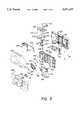
- FIG. 3is an exploded perspective view of a recyclable single use camera utilizing the flash charging and control circuit of FIG. 1;
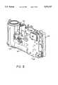
- FIG. 4is a front perspective view of the single use camera shown in FIG. 3;
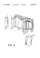
- FIG. 5is a partial front perspective view of the body of the single use camera shown in FIGS. 3 and 4;
- FIG. 6is a partially exploded rear view of the camera shown in FIGS. 3-5;
- FIG. 7is a partial rear view of the single use camera of FIG. 6 showing the reloading of a film cassette.
- the cameraincludes a body 14, an optical system 16, two actuating mechanisms 18 and 19, a viewfinder 20 and a flash device 22 including a flash tube 24.
- the camera body 14is adapted to receive and locate photographic film in a predetermined exposure position relative to the other camera components.
- Actuating mechanism 18initiates a sequence which exposes the film through optical system 16 with supplemental illumination from flash device 22.
- Activating mechanism 19initiates a flash charging cycle prior to the exposure sequence.
- the camerais pointed at the intended subject with the aid of viewfinder 20.
- operation of the flash device 22is selected by the user, when needed, by momentary depression of a separate activating mechanism 19.
- Other approachesmight be employed, however, including flash actuation with every exposure, which is typical of some single use cameras that have few and inexpensive components.
- Also included within the scope of the inventionare single multi-stage actuation buttons and switches for sequentially initiating the charging and exposure cycles.
- the flash charging and control circuit 12includes a direct current power source 26, a self-oscillating flash charging circuit 28, a charge storage device in the form of a capacitor 30, an oscillation arresting circuit 32, a flash trigger circuit 34 and the flash tube 24.
- Power source 26includes one or more batteries 36 of predetermined voltage, supplied with the camera in this preferred embodiment and without provision for replacement.
- the self-oscillating charging circuit 28includes a voltage converting transformer having primary and secondary windings 38 and 40, respectively; a momentary switch 42, for initiating oscillations in the circuit 28; a resistor 44 in series with the momentary switch; ganged transistors 46 and 48, acting as switching elements for supporting and maintaining the oscillations; and a diode 50 for rectifying current induced in the secondary windings 40 of the transformer.
- Chargingis initiated by momentary depression of activating mechanism 19 which closes the momentary switch 42, thereby establishing current flow through resistor 44, transistors 46 and 48 and primary transformer winding 38.
- the switch 42connects the base of transistor 46 to battery 26 through resistor 44.
- Current flowing from the battery into the base of transistor 46is multiplied by a transistor gain of fifty (50) and flows to the base of transistor 48.
- the currentis multiplied again at transistor 48, with a gain of two hundred (200), and flows through the collector of transistor 48 and transformer primary winding 38.
- Currentflows out of capacitor 30, charging the capacitor, and into the base of transistor 46, providing positive feedback.
- Oscillation arresting circuit 32includes a voltage sensor 52 and a digital pnp transistor or gate 54.
- the voltageis sensed by a neon ready light 56 in series with a zener diode 58.
- the neon ready lightbegins conducting at two hundred seventy volts (270 v.), but the voltage drop across the ready light falls to two hundred and twenty volts (220 v.) when it is conducting.
- the zener diodebreaks down and conducts at one hundred ten volts (110 v.).
- the voltage sensor 52which includes the ready light 56 and zener diode 58 in series, begins conducting at three hundred thirty volts (330 v.), which also represents a predetermined or full charge desired on flash capacitor 30.
- the term full charge on the flash capacitoris used to mean that charge or voltage desired for application to the flash when it is fired.
- neon ready light 56begins to conduct, illuminating the ready light and providing notification to the user there is sufficient charge on flash capacitor 30 to initiate the exposure sequence.
- the capacitor 30is not fully charged, however, and charging continues until the charge on capacitor 30 reaches three hundred thirty volts (330 v).
- zener diode 58begins to conduct, applying current to the base of transistor 54, switching transistor 54 on, and grounding the self-oscillating charging circuit 28. Oscillations in the circuit are arrested, and charging stops.
- the neon ready lightserves several functions. It conducts when the flash capacitor voltage exceeds a ready voltage to indicate when there is sufficient charge on the capacitor to initiate an exposure. It also serves as a component in a voltage sensing trigger circuit that stops charging of the flash capacitor when it reaches a predetermined or full voltage greater than the ready voltage. This permits the use of a zener diode rated for a lower voltage in the voltage sensing circuit without requiring any additional parts.
- the neon lightis part of two electrical loops, each serving the different functions. The first loop includes the capacitor 30, the ready light 56 and resistor 60. This loop conducts continuously when the capacitor charge is above the ready charge, turning the ready light on. The second loop includes the capacitor 30, the ready light 56, the zener diode 58, and the transistor gate 54. This loop controls the charging circuit and conducts momentarily to trigger the charging circuit off when the capacitor charge reaches the predetermined or full charge. The momentary conduction momentarily increases the illumination of the ready light and thereby indicates when the predetermined charge is attained.
- the voltage sensing circuit 52is the neon ready light in series with the zener diode.
- Other componentscould be used, however, according to certain features of the invention.
- the neon light and zener diodeact as a trigger for actuating transistor gate 54, and define a signal path between the flash capacitor 62 and the transistor 54.
- Other components that might be substituted for the diode and lightinclude components that transmit signals by conducting electrons or transmitting photons.
- Resistor 44which is sized small enough to provide current to start the oscillations, is large enough for the digital transistor 54 to stop the oscillations even with momentary switch 42 still closed.
- the flash triggering circuit 34is used in commercially available single use cameras, and will not be described in detail. Briefly, the circuit 34 includes a triggering capacitor 62, a voltage converting transformer 64, a flash triggering electrode 66 and a synchronizing switch 68. Triggering capacitor 62 is charged by current flow through secondary winding 40 at the same time and in similar manner as flash capacitor 30. In operation, synchronizing switch 68 is closed by the camera shutter mechanism at the proper time in the exposure sequence. Capacitor 62 discharges through the primary windings of voltage converting transformer 64, inducing four thousand volts (4 kv.) in triggering electrode 66, and ionizing the gas in flash discharge tube 24. Flash capacitor 30 then discharges through the flash tube 24, exciting the gas and producing flash illumination.
- Triggering capacitor 62is charged by current flow through secondary winding 40 at the same time and in similar manner as flash capacitor 30.
- synchronizing switch 68is closed by the camera shutter mechanism at the proper time in the exposure sequence.
- an oscillation arresting deviceis coupled directly through a voltage sensor to the flash capacitor, and is not ratioed through inductive components or timed with capacitive circuits.
- Inexpensive componentsprovide relatively precise charging control automatically to reduce undue battery drain and free the user for photographic composition.
- the phrase "direct coupling,” as used in the present specification and claims,is intended to cover primarily resistive couplings, including neon lights and zener diodes, but excluding those that are primarily inductive or capacitive.
- the flash charging cycleis reinitiated automatically by actuation of the flash device.
- the self-oscillating charging cycleis restarted, and the oscillations continue as before.
- a capacitor 47provides filtering on the base of transistor 46 to keep the circuit from inadvertently turning on due to undesirable noise from, for example, battery bounce or the neon ready light 56 turning off.
- Capacitor 47preferably has a value of 470 pico farads in order that the aforedescribed feedback loop can overcome the effect of capacitor 47 to restart the self-oscillating charging cycle.
- values of capacitor 47might range from two hundred pico farads (200 pf) to one thousand pico farads (1000 pf). A value of six thousand eight hundred pico farads (6800 pf) was tried and is considered too high, according to this feature, because it prevents reinitiation of the charging sequence when the flash is fired.
- the capacitor 47might have other values according to other aspects of the invention.
- the flash charging and control circuit 12can be contained within the assemblage of a camera, such as a recyclable single use camera 100 having three major structural components; a main body or frame 102, a front cover 120 which is attached to the front of the body, and a rear cover 130 which is attached to the rear of the body.
- a camerasuch as a recyclable single use camera 100 having three major structural components; a main body or frame 102, a front cover 120 which is attached to the front of the body, and a rear cover 130 which is attached to the rear of the body.
- the body 102includes a pair of formed chambers 104, 106 for respectively retaining a film cassette 108 and a take-up roll, such as spool 110.
- the pair of chambers 104, 106are oppositely disposed relative to an exposure gate 107, FIG. 7.
- the body 102additionally supports the following camera parts which are attached to the body prior to the attachment of the covers 120, 130: a taking lens 112 which is attached to the front of the body 102 by means of a retainer 114 and a support plate 116 sandwiching the lens therebetween; wherein the support plate has a contact switch 117; and a plastic viewfinder 118.
- the viewfinder 118may be a one-piece viewfinder comprising a support and two optically aligned lenses, all of which may be molded together from a common material in a single molding process in accordance with the invention disclosed in commonly owned U.S. Pat. No. 5,353,165. The disclosure of this patent is incorporated by reference herein.
- a shutter mechanism 119consisting of a keeper plate 122 having a depressible shutter release portion for tripping a shutter blade 124, biased by a spring 123 via a high-energy lever 126, which is also biased by helical spring 127; a film advancing and metering mechanism consisting of a thumbwheel 128 which engages the spool (not shown) of the loaded film cassette 108, a sprocket 132 for engaging film perforations having a spring biased portion extending into a rotable cam 134 which engages a metering lever 136 which is biased by means of a spring 138, the cam having an extending portion for contacting a frame counter 140; a light baffle 142 which is mounted into the rear of the body 102 and into the exposure gate 107, FIG.
- the flash charging and control circuit 12is made operable, preferably according to this particular embodiment, by a one touch cantilevered portion 19 of the front cover 102, FIG. 4.
- the flash assemblymay include an anamorphic lens 22 (FIG. 5) as disclosed in the commonly assigned utility patent application referred to above, the disclosure of which is incorporated by reference herein.
- the front cover 120 and the rear cover 130are sandwiched and held together along with the body 102, by means discussed subsequently, to form an assembled camera.
- a decorative label 152may be subsequently attached to the finished camera 100 to deter a user from opening the camera and provide a convenient place for product identification and operational information.
- single use camerassuch as the described camera 100
- Sakai, et al. U.S. Pat. No. 5,329,330Therefore, certain parts of the cameras are designed to last through a suitable number of cycles of sale, use, reconstruction, and resale. Conversely, for quality reasons, among others, certain parts should be replaced each time a camera is reconstructed.
- An efficient recycling programrequires a number of competing concerns to be reconciled.
- the manufacturer/recyclerwants to facilitate easy access to the exposed film when removed by the photofinisher. This ensures that the reusable components are not damaged.
- access to the interior of the camera by the consumer/photographeris undesirable because it increases the risk of damage to and/or contamination of the interior of the camera and its reusable components.
- a living hinge in a film cassette door for a single use camerais disclosed in commonly owned U.S. Pat. No. 5,255,041, the disclosure of which is incorporated by reference herein.
- the door 154may be connected to the rear cover by a frangible connection integrally formed therewith and designed to break away from the remainder of the rear cover. In either case, the opening of the door 154 provides access to film cassette 108 without damaging or exposing the camera parts attached to the camera body 102.
- a second door 156can also be provided on the rear cover 130 to be flexibly opened or broken away by the photofinisher to remove the flash battery 36, if desired. See FIG. 6.
- the camera 100is then turned over to the manufacturer for recycling as will now be described with reference to the FIGS. 3-7.
- the recycling processmay comprise the following steps: First, the front cover 120 and rear cover 130 may be detached from the camera body 102.
- the covers 120, 130 and body 102may utilize a number of means for attaching the structural parts together; for example, hook and/or press fitting members may be used, or the parts can be ultrasonically welded together.
- each covermay have a suitable number of conventional releasable hook structures (one of which is shown at 161, 162) or other attachment means for allowing removal of the covers from the body.
- the coversmay be made from a recyclable plastic such as polystyrene and can be sent to be pulverized.
- the pulverized materialmay be blended with virgin materials and new covers or other parts molded therefrom.
- the prewind spool 110, the taking lens 112, and light baffle 142(unless integrally molded with the body 102) also are removed.
- the taking lens 112also may be similarly pulverized with other lenses, blended with virgin materials, and new lenses made therefrom.
- Other partstypically more costly components designed to be reused, such as the main body 102 and the major parts supported by the body, e.g., the viewfinder 118, shutter mechanism 119, film advancing and metering mechanism, and flashing charging and control circuit 12 may be examined carefully for wear or damage. Those parts deemed damaged or worn may be removed from the body 102 and replaced with new parts. Those remaining reusable parts, such as the camera flash charging and control circuit 12, shutter mechanism 119, etc., that can be reused remain supported by the camera body, for construction into a camera 100.
- a new front cover 120is then fitted to the front face of the body 102 and an unexposed roll of film 109 contained within a fresh cassette 108 is loaded into the film cartridge chamber 104. A leading portion of the film 109 contained with the cassette 108 is then engaged with the take up spool 110, housed within the body chamber 106, as is conventionally known. A new rear cover 130 is then snapped or otherwise attached onto the rear of the camera body 102 and/or to the front cover 120 by any of the attachment means discussed above.
- a less rigorous but not preferred recycling processmay be employed in which the covers 120, 130 are not replaced with new parts.
- the cameraswould be inspected visually after the back cover is removed. If the camera was deemed reusable as a whole, a new film 109 then would be reloaded into the film chamber and threaded onto the take-up spool. The rear cover then would be re-attached to the camera body and/or front cover.
- the film 109may be then prewound onto the take-up spool 110, which is supported for rotation in chamber 106 so that the film is wound back into the cassette 108 as the film is being exposed.
- a limited torque electric screwdriver or other toolmay be used to prewind the film onto the prewind spool. If a new take-up spool is not provided and if the exposed end of the prewind spool previously was deformed to prevent reuse of the spool for prewinding purposes, sufficient heat and/or pressure must be applied to rotate the spool.
- At least one wind and trip checkmay be done to simulate taking a picture, thereby bringing the counter down to 24 (assuming a 24 exposure roll).
- the camerathen may be inserted into a cardboard casing or a label such as 152 attached thereto by adhesive.
- the recycled camerathen may be humidity sealed in a foil wrap, plastic bag or the like, and packaged in an outer cardboard box for sale.
- the recycled single use camera 100utilizing previously used single use camera parts, such as the flash charging and control circuit 12, is now fully assembled and ready for consumer use.
Landscapes
- Stroboscope Apparatuses (AREA)
- Discharge-Lamp Control Circuits And Pulse- Feed Circuits (AREA)
- Structure And Mechanism Of Cameras (AREA)
- Charge And Discharge Circuits For Batteries Or The Like (AREA)
Abstract
Description
______________________________________ PARTS LIST FOR FIGS. 1-7 ______________________________________ 10 Camera. 12 Flash charging and control circuit. 14 Camera body. 16 Optical system. 18,19 Actuating mechanisms. 20 Viewfinder. 22 Flash device. 24 Flash tube. 26 Power source. 28 Self-oscillating flash charging circuit. 30 Capacitor. 32 Oscillation arresting circuit. 34 Flash trigger circuit. 36 Batteries. 38 Primary transformer winding. 40 Secondary transformer winding. 42 Momentary switch. 44 Resistor. 46 Transistor. 47 Capacitor. 48 Transistor. 50 Rectifying diode. 52 Voltage sensor. 54 Digital transistor. 56 Neon ready light. 58 Zener diode. 62 Triggering capacitor. 64 Transformer. 66 Flash triggering electrode. 68 Synchronizing switch. 100 Single-use camera. 102 Body. 104 Film cassette chamber. 106 Take-up chamber. 107 Exposure gate. 108 Film cassette. 109 Film. 110 Take-up spool. 112 Taking lens. 114 Retainer. 116 Support plate. 118 Viewfinder. 119 Shutter mechanism. 120 Front cover. 122 Keeper plate. 123 Spring. 124 Shutter blade. 126 High energy lever. 127 Helical spring. 128 Thumb wheel. 130 Rear cover. 132 Sprocket. 134 Rotatable cam. 136 Metering lever. 138 Spring. 140 Frame counter. 142 Baffle. 148 Circuit board. 152 Label. 154 First door. 156 Second door. ______________________________________
Claims (28)
Priority Applications (8)
| Application Number | Priority Date | Filing Date | Title |
|---|---|---|---|
| US08/330,658US5574337A (en) | 1994-06-30 | 1994-10-28 | Single touch flash charger control |
| PCT/US1995/008908WO1996001034A2 (en) | 1994-06-30 | 1995-06-23 | Single touch flash charger control |
| AU32703/95AAU682979B2 (en) | 1994-06-30 | 1995-06-23 | Single touch flash charger control |
| DE69523264TDE69523264T2 (en) | 1994-06-30 | 1995-06-23 | Single-touch flash charge controller |
| CA002169189ACA2169189A1 (en) | 1994-06-30 | 1995-06-23 | Single touch flash charger control |
| EP95929311AEP0716801B1 (en) | 1994-06-30 | 1995-06-23 | Single touch flash charger control |
| JP8503503AJPH09502569A (en) | 1994-06-30 | 1995-06-23 | Control of single touch flash charging circuit |
| CN95190600ACN1049318C (en) | 1994-06-30 | 1995-06-23 | Single touch flash charger control |
Applications Claiming Priority (3)
| Application Number | Priority Date | Filing Date | Title |
|---|---|---|---|
| US26941594A | 1994-06-30 | 1994-06-30 | |
| US32724494A | 1994-10-21 | 1994-10-21 | |
| US08/330,658US5574337A (en) | 1994-06-30 | 1994-10-28 | Single touch flash charger control |
Related Parent Applications (1)
| Application Number | Title | Priority Date | Filing Date |
|---|---|---|---|
| US32724494AContinuation-In-Part | 1994-06-30 | 1994-10-21 |
Publications (1)
| Publication Number | Publication Date |
|---|---|
| US5574337Atrue US5574337A (en) | 1996-11-12 |
Family
ID=27402178
Family Applications (1)
| Application Number | Title | Priority Date | Filing Date |
|---|---|---|---|
| US08/330,658Expired - LifetimeUS5574337A (en) | 1994-06-30 | 1994-10-28 | Single touch flash charger control |
Country Status (8)
| Country | Link |
|---|---|
| US (1) | US5574337A (en) |
| EP (1) | EP0716801B1 (en) |
| JP (1) | JPH09502569A (en) |
| CN (1) | CN1049318C (en) |
| AU (1) | AU682979B2 (en) |
| CA (1) | CA2169189A1 (en) |
| DE (1) | DE69523264T2 (en) |
| WO (1) | WO1996001034A2 (en) |
Cited By (21)
| Publication number | Priority date | Publication date | Assignee | Title |
|---|---|---|---|---|
| US5814948A (en)* | 1997-01-14 | 1998-09-29 | Eastman Kodak Company | Flash circuit for low cost cameras |
| US5832311A (en)* | 1996-09-13 | 1998-11-03 | Concord Camera Corp. | Single use camera with battery located in film spool |
| US5862414A (en)* | 1996-09-13 | 1999-01-19 | Concord Camera Corp. | Film and battery loading method for a single use camera such as a single use APS camera and a camera loaded according to the same |
| US5930545A (en)* | 1997-11-13 | 1999-07-27 | Eastman Kodak Company | Camera with space-saving elastomeric switch |
| US5943521A (en)* | 1998-03-10 | 1999-08-24 | Eastman Kodak Company | Camera with movable protective cover supported for pivoting to activate switch |
| US6035141A (en)* | 1999-02-18 | 2000-03-07 | Eastman Kodak Company | Optical data recording circuit for a film camera |
| US6038408A (en)* | 1999-02-18 | 2000-03-14 | Eastman Kodak Company | Optical data recording circuit for a film camera |
| US6054814A (en)* | 1998-09-08 | 2000-04-25 | Eastman Kodak Company | Camera flash charging apparatus for low cost single use camera |
| US6081666A (en)* | 1996-09-13 | 2000-06-27 | Concord Camera Corp. | Film and battery loading method for a single use camera such as a single use APS camera and a camera loaded according to the same |
| US6085037A (en)* | 1996-09-13 | 2000-07-04 | Concord Camera Corp. | APS camera structure for film preloading |
| US6198880B1 (en)* | 1998-05-28 | 2001-03-06 | Konica Corporation | Lens-fitted film unit having a touch sensor |
| US6198881B1 (en) | 1999-10-05 | 2001-03-06 | Eastman Kodak Company | Loading methods for camera frame assemblies subject to static charging during film scrolling |
| EP1091241A1 (en)* | 1999-10-05 | 2001-04-11 | Eastman Kodak Company | Camera frame assembly having standby battery |
| US6233402B1 (en) | 1999-10-05 | 2001-05-15 | Eastman Kodak Company | Camera frame assembly having actuable battery contact |
| US6314239B1 (en)* | 1999-06-25 | 2001-11-06 | Fuji Photo Film Co., Ltd. | Device for preventing unauthorized recycling of lens-fitted photo film unit |
| US6529687B1 (en) | 1999-03-30 | 2003-03-04 | Concord Camera Corp. | APS camera and method |
| US6574430B1 (en) | 2001-12-27 | 2003-06-03 | Eastman Kodak Company | Camera electronic system and method of assembling same |
| US6768869B2 (en) | 2002-04-23 | 2004-07-27 | Eastman Kodak Company | Camera body, camera and method for assembling same |
| US6826365B1 (en) | 2003-10-06 | 2004-11-30 | Eastman Kodak Company | Battery saving flash charger control |
| US6871016B2 (en) | 2001-12-27 | 2005-03-22 | Eastman Kodak Company | Recyclable camera and method for assembling same |
| CN1305352C (en)* | 2002-12-31 | 2007-03-14 | 圆创科技股份有限公司 | Charging IC for camera flash |
Families Citing this family (5)
| Publication number | Priority date | Publication date | Assignee | Title |
|---|---|---|---|---|
| EP0755174A3 (en)* | 1995-07-18 | 1998-12-16 | Eastman Kodak Company | Static immunity for single touch flash charger control |
| US5781804A (en)* | 1996-11-19 | 1998-07-14 | Eastman Kodak Company | Single touch flash charger circuit with timer control |
| JP2007536634A (en) | 2004-05-04 | 2007-12-13 | フィッシャー−ローズマウント・システムズ・インコーポレーテッド | Service-oriented architecture for process control systems |
| JP2008261896A (en)* | 2007-04-10 | 2008-10-30 | Sony Corp | Imaging apparatus, stroboscopic device and charge control method |
| CN101730362B (en)* | 2008-10-27 | 2013-02-20 | 佛山普立华科技有限公司 | Flash lamp control circuit |
Citations (62)
| Publication number | Priority date | Publication date | Assignee | Title |
|---|---|---|---|---|
| US2933027A (en)* | 1951-10-05 | 1960-04-19 | Beaurline Ind Inc | Camera |
| US3310723A (en)* | 1963-10-18 | 1967-03-21 | Honeywell Inc | High voltage power supply for photographic flash apparatus |
| US3651372A (en)* | 1969-08-09 | 1972-03-21 | Konishiroku Photo Ind | Warning indicator apparatus for use in a camera having a flash discharge device contained therein |
| US3731586A (en)* | 1970-10-16 | 1973-05-08 | Minnesota Mining & Mfg | Camera case with retractable viewfinder |
| US3764849A (en)* | 1972-03-24 | 1973-10-09 | Minolta Camera Kk | Electronic flash charging and triggering circuitry |
| US3780344A (en)* | 1971-09-07 | 1973-12-18 | Gte Sylvania Inc | Charge regulating circuit for flash lamp storage capacitor |
| US3859563A (en)* | 1973-07-09 | 1975-01-07 | Lumedyne Inc | Voltage converter and regulator |
| DE2430481A1 (en)* | 1973-06-28 | 1975-01-16 | Honeywell Inc | Electronic flash gun charging arrangement - with some magnetic energy retained in the transformer core, decreased time to charge storage capacitor |
| US3882358A (en)* | 1973-06-26 | 1975-05-06 | Ibm | Anti-holdover charging circuit for flash lamp |
| US4001640A (en)* | 1973-01-02 | 1977-01-04 | Polaroid Corporation | Single trigger photographic strobe unit |
| US4007469A (en)* | 1975-04-21 | 1977-02-08 | Polaroid Corporation | Photographic apparatus with plurality of selectively determinable operational modes |
| US4065700A (en)* | 1976-07-06 | 1977-12-27 | Theodore Liebman | D. C. powered strobe light |
| US4067028A (en)* | 1975-03-27 | 1978-01-03 | Agfa-Gevaert, Ag | Proper synchronization of the firing of electronic flash units |
| US4082983A (en)* | 1975-06-23 | 1978-04-04 | Rollei Of America, Inc. | Capacitor charging system for electronic flash apparatus |
| US4084167A (en)* | 1976-03-17 | 1978-04-11 | West Electric Company, Ltd. | Flash and camera device |
| US4130780A (en)* | 1976-11-09 | 1978-12-19 | Itsuki Ban | Electronic photoflash |
| US4163178A (en)* | 1976-04-16 | 1979-07-31 | Fuji Photo Optical Co., Ltd. | Flash light discharge device |
| US4259615A (en)* | 1978-03-20 | 1981-03-31 | West Electric Company, Ltd. | Photographic flash device |
| FR2470515A1 (en)* | 1979-11-26 | 1981-05-29 | Fuji Koeki Corp | POWER SUPPLY FOR AN ELECTRIC FLASH DEVICE |
| US4322143A (en)* | 1979-06-27 | 1982-03-30 | Balda-Werke | Electronic flash for a camera |
| US4323822A (en)* | 1977-09-25 | 1982-04-06 | Fuji Koeki Corporation | Electric flash device |
| US4348087A (en)* | 1981-04-03 | 1982-09-07 | Polaroid Corporation | Photographic system for automatically charging electronic flash |
| US4404497A (en)* | 1979-04-21 | 1983-09-13 | Fuji Koeki Corporation | Power supplying apparatus |
| DE3347488A1 (en)* | 1982-12-29 | 1984-07-12 | Olympus Optical Co., Ltd., Tokio/Tokyo | POWER SUPPLY FOR AN ELECTRONIC FLASH UNIT |
| GB2133644A (en)* | 1983-01-14 | 1984-07-25 | Fuji Koeki Corp | Photographic flash apparatus |
| US4511233A (en)* | 1980-05-14 | 1985-04-16 | Nippon Kogaku K.K. | Charge control device in a flash device for a camera |
| US4523248A (en)* | 1982-06-04 | 1985-06-11 | U.S. Philips Corporation | Safety circuit for a detachable connecting cable |
| US4540265A (en)* | 1983-01-24 | 1985-09-10 | Eastman Kodak Company | Energy-saving electronic flash apparatus |
| US4628229A (en)* | 1983-02-15 | 1986-12-09 | Olympus Optical Company, Ltd | Flashlight emission apparatus |
| US4777507A (en)* | 1988-01-20 | 1988-10-11 | Eastman Kodak Company | Control system for an electronic flash unit |
| US4812863A (en)* | 1987-02-17 | 1989-03-14 | Fuji Photo Film Co., Ltd. | Lens-fitted photographic film package |
| US4812866A (en)* | 1987-02-06 | 1989-03-14 | Fuji Photo Film Co., Ltd. | Photographic film package |
| US4855774A (en)* | 1986-12-01 | 1989-08-08 | Fuji Photo Film Co., Ltd. | Lens-fitted photographic film package |
| US4884087A (en)* | 1986-08-20 | 1989-11-28 | Fuji Photo Film Co., Ltd. | Photographic film package and method of making the same |
| US4890130A (en)* | 1986-10-17 | 1989-12-26 | Fuji Photo Film Co., Ltd. | Lens-fitted photographic film package |
| US4912499A (en)* | 1989-01-17 | 1990-03-27 | Eastman Kodak Company | Camera apparatus |
| US4924149A (en)* | 1986-12-23 | 1990-05-08 | Asahi Kogaku Kogyo Kabushiki Kaisha | Apparatus for controlling the charging of a main capacitor of a flash unit |
| EP0398526A1 (en)* | 1989-04-28 | 1990-11-22 | Minnesota Mining And Manufacturing Company | Improved power supply circuit for a gaseous discharge tube device |
| US4989029A (en)* | 1988-04-20 | 1991-01-29 | Minolta Camera Kabushiki Kaisha | Camera with control apparatus for charging storage capacitor for flash light emission |
| US4994846A (en)* | 1988-04-11 | 1991-02-19 | Asahi Kogaku Kogyo Kabushiki Kaisha | Auto strobe camera |
| JPH0365129A (en)* | 1989-08-01 | 1991-03-20 | Mitsui Petrochem Ind Ltd | Culture device |
| US5019845A (en)* | 1989-06-23 | 1991-05-28 | Olympus Optical Co., Ltd. | Flash device for camera |
| US5021811A (en)* | 1990-06-21 | 1991-06-04 | Eastman Kodak Company | Recycleable element recycle counter and method |
| US5068575A (en)* | 1991-02-21 | 1991-11-26 | Eastman Kodak Company | Indirect storage capacitor voltage sensing means for a flyback type DC-to-DC converter |
| US5101335A (en)* | 1990-12-26 | 1992-03-31 | Eastman Kodak Company | DC-to-DC converter using coupled inductor current sensing and predetermined on time |
| US5138362A (en)* | 1988-06-30 | 1992-08-11 | Asahikogaku Kogyo Kabushiki Kaisha | Auto strobe camera |
| US5170199A (en)* | 1990-07-09 | 1992-12-08 | Fuji Photo Film Co., Ltd. | Lens-fitted photographic film unit |
| JPH0593951A (en)* | 1991-09-30 | 1993-04-16 | Fuji Photo Optical Co Ltd | Film unit with lens |
| US5249007A (en)* | 1991-06-26 | 1993-09-28 | West Electric Company Ltd. | Strobe apparatus |
| US5255041A (en)* | 1993-02-11 | 1993-10-19 | Eastman Kodak Company | Single-use camera with door for cartridge receiving chamber |
| US5287134A (en)* | 1992-12-28 | 1994-02-15 | Eastman Kodak Company | Photographic flash apparatus |
| JPH0643525A (en)* | 1992-07-23 | 1994-02-18 | Fuji Photo Film Co Ltd | Stroboscoptic device |
| JPH06130469A (en)* | 1992-10-15 | 1994-05-13 | Fuji Photo Film Co Ltd | Film unit having lens with built-in strobe |
| US5315332A (en)* | 1991-04-11 | 1994-05-24 | Fuji Photo Film Co., Ltd. | Lens-fitted photographic film package and flash unit |
| US5329330A (en)* | 1992-01-31 | 1994-07-12 | Konica Corporation | Film unit with a photographic lens |
| JPH06203987A (en)* | 1993-01-07 | 1994-07-22 | Fuji Photo Film Co Ltd | Stroboscope charging switch device |
| JPH06203989A (en)* | 1993-01-04 | 1994-07-22 | Fuji Photo Film Co Ltd | Stroboscopic device |
| JPH06202208A (en)* | 1993-01-04 | 1994-07-22 | Fuji Photo Film Co Ltd | Charging switch device for stroboscope |
| JPH06203988A (en)* | 1993-01-07 | 1994-07-22 | Fuji Photo Film Co Ltd | Stroboscopic power source circuit and camera using this |
| JPH06208897A (en)* | 1993-01-11 | 1994-07-26 | Fuji Photo Film Co Ltd | Stroboscope light dimming circuit |
| US5337099A (en)* | 1992-07-01 | 1994-08-09 | Fuji Photo Film Co., Ltd. | Lens-fitted photographic film unit with flash device and battery-insulating wrapper |
| US5353165A (en)* | 1992-09-15 | 1994-10-04 | Eastman Kodak Company | One piece viewfinder and fabrication process |
- 1994
- 1994-10-28USUS08/330,658patent/US5574337A/ennot_activeExpired - Lifetime
- 1995
- 1995-06-23WOPCT/US1995/008908patent/WO1996001034A2/enactiveIP Right Grant
- 1995-06-23DEDE69523264Tpatent/DE69523264T2/ennot_activeExpired - Fee Related
- 1995-06-23CACA002169189Apatent/CA2169189A1/ennot_activeAbandoned
- 1995-06-23AUAU32703/95Apatent/AU682979B2/ennot_activeCeased
- 1995-06-23EPEP95929311Apatent/EP0716801B1/ennot_activeExpired - Lifetime
- 1995-06-23JPJP8503503Apatent/JPH09502569A/enactivePending
- 1995-06-23CNCN95190600Apatent/CN1049318C/ennot_activeExpired - Fee Related
Patent Citations (63)
| Publication number | Priority date | Publication date | Assignee | Title |
|---|---|---|---|---|
| US2933027A (en)* | 1951-10-05 | 1960-04-19 | Beaurline Ind Inc | Camera |
| US3310723A (en)* | 1963-10-18 | 1967-03-21 | Honeywell Inc | High voltage power supply for photographic flash apparatus |
| US3651372A (en)* | 1969-08-09 | 1972-03-21 | Konishiroku Photo Ind | Warning indicator apparatus for use in a camera having a flash discharge device contained therein |
| US3731586A (en)* | 1970-10-16 | 1973-05-08 | Minnesota Mining & Mfg | Camera case with retractable viewfinder |
| US3780344A (en)* | 1971-09-07 | 1973-12-18 | Gte Sylvania Inc | Charge regulating circuit for flash lamp storage capacitor |
| US3764849A (en)* | 1972-03-24 | 1973-10-09 | Minolta Camera Kk | Electronic flash charging and triggering circuitry |
| US4001640A (en)* | 1973-01-02 | 1977-01-04 | Polaroid Corporation | Single trigger photographic strobe unit |
| US3882358A (en)* | 1973-06-26 | 1975-05-06 | Ibm | Anti-holdover charging circuit for flash lamp |
| DE2430481A1 (en)* | 1973-06-28 | 1975-01-16 | Honeywell Inc | Electronic flash gun charging arrangement - with some magnetic energy retained in the transformer core, decreased time to charge storage capacitor |
| US3859563A (en)* | 1973-07-09 | 1975-01-07 | Lumedyne Inc | Voltage converter and regulator |
| US4067028A (en)* | 1975-03-27 | 1978-01-03 | Agfa-Gevaert, Ag | Proper synchronization of the firing of electronic flash units |
| US4007469A (en)* | 1975-04-21 | 1977-02-08 | Polaroid Corporation | Photographic apparatus with plurality of selectively determinable operational modes |
| US4082983A (en)* | 1975-06-23 | 1978-04-04 | Rollei Of America, Inc. | Capacitor charging system for electronic flash apparatus |
| US4084167A (en)* | 1976-03-17 | 1978-04-11 | West Electric Company, Ltd. | Flash and camera device |
| US4163178A (en)* | 1976-04-16 | 1979-07-31 | Fuji Photo Optical Co., Ltd. | Flash light discharge device |
| US4271375A (en)* | 1976-04-16 | 1981-06-02 | Fuji Photo Optical Co., Ltd. | Flash light discharge device |
| US4065700A (en)* | 1976-07-06 | 1977-12-27 | Theodore Liebman | D. C. powered strobe light |
| US4130780A (en)* | 1976-11-09 | 1978-12-19 | Itsuki Ban | Electronic photoflash |
| US4323822A (en)* | 1977-09-25 | 1982-04-06 | Fuji Koeki Corporation | Electric flash device |
| US4259615A (en)* | 1978-03-20 | 1981-03-31 | West Electric Company, Ltd. | Photographic flash device |
| US4404497A (en)* | 1979-04-21 | 1983-09-13 | Fuji Koeki Corporation | Power supplying apparatus |
| US4322143A (en)* | 1979-06-27 | 1982-03-30 | Balda-Werke | Electronic flash for a camera |
| FR2470515A1 (en)* | 1979-11-26 | 1981-05-29 | Fuji Koeki Corp | POWER SUPPLY FOR AN ELECTRIC FLASH DEVICE |
| US4511233A (en)* | 1980-05-14 | 1985-04-16 | Nippon Kogaku K.K. | Charge control device in a flash device for a camera |
| US4348087A (en)* | 1981-04-03 | 1982-09-07 | Polaroid Corporation | Photographic system for automatically charging electronic flash |
| US4523248A (en)* | 1982-06-04 | 1985-06-11 | U.S. Philips Corporation | Safety circuit for a detachable connecting cable |
| DE3347488A1 (en)* | 1982-12-29 | 1984-07-12 | Olympus Optical Co., Ltd., Tokio/Tokyo | POWER SUPPLY FOR AN ELECTRONIC FLASH UNIT |
| GB2133644A (en)* | 1983-01-14 | 1984-07-25 | Fuji Koeki Corp | Photographic flash apparatus |
| US4540265A (en)* | 1983-01-24 | 1985-09-10 | Eastman Kodak Company | Energy-saving electronic flash apparatus |
| US4628229A (en)* | 1983-02-15 | 1986-12-09 | Olympus Optical Company, Ltd | Flashlight emission apparatus |
| US4884087A (en)* | 1986-08-20 | 1989-11-28 | Fuji Photo Film Co., Ltd. | Photographic film package and method of making the same |
| US4890130A (en)* | 1986-10-17 | 1989-12-26 | Fuji Photo Film Co., Ltd. | Lens-fitted photographic film package |
| US4855774A (en)* | 1986-12-01 | 1989-08-08 | Fuji Photo Film Co., Ltd. | Lens-fitted photographic film package |
| US4924149A (en)* | 1986-12-23 | 1990-05-08 | Asahi Kogaku Kogyo Kabushiki Kaisha | Apparatus for controlling the charging of a main capacitor of a flash unit |
| US4812866A (en)* | 1987-02-06 | 1989-03-14 | Fuji Photo Film Co., Ltd. | Photographic film package |
| US4812863A (en)* | 1987-02-17 | 1989-03-14 | Fuji Photo Film Co., Ltd. | Lens-fitted photographic film package |
| US4777507A (en)* | 1988-01-20 | 1988-10-11 | Eastman Kodak Company | Control system for an electronic flash unit |
| US4994846A (en)* | 1988-04-11 | 1991-02-19 | Asahi Kogaku Kogyo Kabushiki Kaisha | Auto strobe camera |
| US4989029A (en)* | 1988-04-20 | 1991-01-29 | Minolta Camera Kabushiki Kaisha | Camera with control apparatus for charging storage capacitor for flash light emission |
| US5138362A (en)* | 1988-06-30 | 1992-08-11 | Asahikogaku Kogyo Kabushiki Kaisha | Auto strobe camera |
| US4912499A (en)* | 1989-01-17 | 1990-03-27 | Eastman Kodak Company | Camera apparatus |
| EP0398526A1 (en)* | 1989-04-28 | 1990-11-22 | Minnesota Mining And Manufacturing Company | Improved power supply circuit for a gaseous discharge tube device |
| US5019845A (en)* | 1989-06-23 | 1991-05-28 | Olympus Optical Co., Ltd. | Flash device for camera |
| JPH0365129A (en)* | 1989-08-01 | 1991-03-20 | Mitsui Petrochem Ind Ltd | Culture device |
| US5021811A (en)* | 1990-06-21 | 1991-06-04 | Eastman Kodak Company | Recycleable element recycle counter and method |
| US5170199A (en)* | 1990-07-09 | 1992-12-08 | Fuji Photo Film Co., Ltd. | Lens-fitted photographic film unit |
| US5101335A (en)* | 1990-12-26 | 1992-03-31 | Eastman Kodak Company | DC-to-DC converter using coupled inductor current sensing and predetermined on time |
| US5068575A (en)* | 1991-02-21 | 1991-11-26 | Eastman Kodak Company | Indirect storage capacitor voltage sensing means for a flyback type DC-to-DC converter |
| US5315332A (en)* | 1991-04-11 | 1994-05-24 | Fuji Photo Film Co., Ltd. | Lens-fitted photographic film package and flash unit |
| US5249007A (en)* | 1991-06-26 | 1993-09-28 | West Electric Company Ltd. | Strobe apparatus |
| JPH0593951A (en)* | 1991-09-30 | 1993-04-16 | Fuji Photo Optical Co Ltd | Film unit with lens |
| US5329330A (en)* | 1992-01-31 | 1994-07-12 | Konica Corporation | Film unit with a photographic lens |
| US5337099A (en)* | 1992-07-01 | 1994-08-09 | Fuji Photo Film Co., Ltd. | Lens-fitted photographic film unit with flash device and battery-insulating wrapper |
| JPH0643525A (en)* | 1992-07-23 | 1994-02-18 | Fuji Photo Film Co Ltd | Stroboscoptic device |
| US5353165A (en)* | 1992-09-15 | 1994-10-04 | Eastman Kodak Company | One piece viewfinder and fabrication process |
| JPH06130469A (en)* | 1992-10-15 | 1994-05-13 | Fuji Photo Film Co Ltd | Film unit having lens with built-in strobe |
| US5287134A (en)* | 1992-12-28 | 1994-02-15 | Eastman Kodak Company | Photographic flash apparatus |
| JPH06203989A (en)* | 1993-01-04 | 1994-07-22 | Fuji Photo Film Co Ltd | Stroboscopic device |
| JPH06202208A (en)* | 1993-01-04 | 1994-07-22 | Fuji Photo Film Co Ltd | Charging switch device for stroboscope |
| JPH06203987A (en)* | 1993-01-07 | 1994-07-22 | Fuji Photo Film Co Ltd | Stroboscope charging switch device |
| JPH06203988A (en)* | 1993-01-07 | 1994-07-22 | Fuji Photo Film Co Ltd | Stroboscopic power source circuit and camera using this |
| JPH06208897A (en)* | 1993-01-11 | 1994-07-26 | Fuji Photo Film Co Ltd | Stroboscope light dimming circuit |
| US5255041A (en)* | 1993-02-11 | 1993-10-19 | Eastman Kodak Company | Single-use camera with door for cartridge receiving chamber |
Cited By (24)
| Publication number | Priority date | Publication date | Assignee | Title |
|---|---|---|---|---|
| US6081666A (en)* | 1996-09-13 | 2000-06-27 | Concord Camera Corp. | Film and battery loading method for a single use camera such as a single use APS camera and a camera loaded according to the same |
| US5832311A (en)* | 1996-09-13 | 1998-11-03 | Concord Camera Corp. | Single use camera with battery located in film spool |
| US5862414A (en)* | 1996-09-13 | 1999-01-19 | Concord Camera Corp. | Film and battery loading method for a single use camera such as a single use APS camera and a camera loaded according to the same |
| US6404993B1 (en)* | 1996-09-13 | 2002-06-11 | Concord Camera Corp. | APS camera structure for film preloading |
| US6085037A (en)* | 1996-09-13 | 2000-07-04 | Concord Camera Corp. | APS camera structure for film preloading |
| US5814948A (en)* | 1997-01-14 | 1998-09-29 | Eastman Kodak Company | Flash circuit for low cost cameras |
| EP0853446A3 (en)* | 1997-01-14 | 1999-10-20 | Eastman Kodak Company | Flash circuit for low cost cameras |
| US5930545A (en)* | 1997-11-13 | 1999-07-27 | Eastman Kodak Company | Camera with space-saving elastomeric switch |
| US5943521A (en)* | 1998-03-10 | 1999-08-24 | Eastman Kodak Company | Camera with movable protective cover supported for pivoting to activate switch |
| US6198880B1 (en)* | 1998-05-28 | 2001-03-06 | Konica Corporation | Lens-fitted film unit having a touch sensor |
| US6054814A (en)* | 1998-09-08 | 2000-04-25 | Eastman Kodak Company | Camera flash charging apparatus for low cost single use camera |
| US6038408A (en)* | 1999-02-18 | 2000-03-14 | Eastman Kodak Company | Optical data recording circuit for a film camera |
| US6035141A (en)* | 1999-02-18 | 2000-03-07 | Eastman Kodak Company | Optical data recording circuit for a film camera |
| US6529687B1 (en) | 1999-03-30 | 2003-03-04 | Concord Camera Corp. | APS camera and method |
| US6314239B1 (en)* | 1999-06-25 | 2001-11-06 | Fuji Photo Film Co., Ltd. | Device for preventing unauthorized recycling of lens-fitted photo film unit |
| US6233402B1 (en) | 1999-10-05 | 2001-05-15 | Eastman Kodak Company | Camera frame assembly having actuable battery contact |
| US6266491B1 (en) | 1999-10-05 | 2001-07-24 | Eastman Kodak Company | Camera frame assembly having standby battery station |
| EP1091241A1 (en)* | 1999-10-05 | 2001-04-11 | Eastman Kodak Company | Camera frame assembly having standby battery |
| US6198881B1 (en) | 1999-10-05 | 2001-03-06 | Eastman Kodak Company | Loading methods for camera frame assemblies subject to static charging during film scrolling |
| US6574430B1 (en) | 2001-12-27 | 2003-06-03 | Eastman Kodak Company | Camera electronic system and method of assembling same |
| US6871016B2 (en) | 2001-12-27 | 2005-03-22 | Eastman Kodak Company | Recyclable camera and method for assembling same |
| US6768869B2 (en) | 2002-04-23 | 2004-07-27 | Eastman Kodak Company | Camera body, camera and method for assembling same |
| CN1305352C (en)* | 2002-12-31 | 2007-03-14 | 圆创科技股份有限公司 | Charging IC for camera flash |
| US6826365B1 (en) | 2003-10-06 | 2004-11-30 | Eastman Kodak Company | Battery saving flash charger control |
Also Published As
| Publication number | Publication date |
|---|---|
| AU3270395A (en) | 1996-01-25 |
| CN1130460A (en) | 1996-09-04 |
| EP0716801B1 (en) | 2001-10-17 |
| JPH09502569A (en) | 1997-03-11 |
| CN1049318C (en) | 2000-02-09 |
| WO1996001034A2 (en) | 1996-01-11 |
| WO1996001034A3 (en) | 1996-02-22 |
| AU682979B2 (en) | 1997-10-23 |
| DE69523264D1 (en) | 2001-11-22 |
| EP0716801A1 (en) | 1996-06-19 |
| DE69523264T2 (en) | 2002-07-11 |
| CA2169189A1 (en) | 1996-01-11 |
Similar Documents
| Publication | Publication Date | Title |
|---|---|---|
| US5574337A (en) | Single touch flash charger control | |
| US5337099A (en) | Lens-fitted photographic film unit with flash device and battery-insulating wrapper | |
| US5034662A (en) | Apparatus for controlling the charging of a main capacitor of a flash unit | |
| US5875357A (en) | Lens-fitted photo film unit and electronic flash device for use therewith | |
| US6345156B1 (en) | Flash unit | |
| US5761541A (en) | Single use camera with flash charging circuit | |
| US5506646A (en) | Test firing of a photographic flash assembly | |
| US4522479A (en) | Flash apparatus with power supply control device | |
| US6339679B1 (en) | Single use camera with built-in electronic flash | |
| JP2858715B2 (en) | Film unit with lens | |
| US4545666A (en) | Light emission blocking device of a camera capable of effecting flashlight photography | |
| JP2710074B2 (en) | Camera control circuit | |
| JPH06203989A (en) | Stroboscopic device | |
| US5721962A (en) | Method of making single-use camera with electronic flash unit from previously used camera parts | |
| US6393221B1 (en) | Electronic flash unit with integrated flash charge switch | |
| JPH06347872A (en) | Stroboscope device | |
| JPH04306626A (en) | Disposable camera equipped with flash lamp | |
| JP3317598B2 (en) | Film unit with lens | |
| JP2004125973A (en) | Lens-fitted photographic film unit | |
| JP2858713B2 (en) | Film unit with lens | |
| JPH0643525A (en) | Stroboscoptic device | |
| JPH10161225A (en) | Information imprinting device of camera | |
| JPH08114836A (en) | Film unit with lens | |
| JPH10293345A (en) | Stroboscope built-in type film unit having lens | |
| JPH06203987A (en) | Stroboscope charging switch device |
Legal Events
| Date | Code | Title | Description |
|---|---|---|---|
| AS | Assignment | Owner name:EASTMAN KODAK COMPANY, NEW YORK Free format text:ASSIGNMENT OF ASSIGNORS INTEREST;ASSIGNOR:DUNSMORE, CLAY A.;REEL/FRAME:007274/0664 Effective date:19941028 | |
| FEPP | Fee payment procedure | Free format text:PAYOR NUMBER ASSIGNED (ORIGINAL EVENT CODE: ASPN); ENTITY STATUS OF PATENT OWNER: LARGE ENTITY | |
| STCF | Information on status: patent grant | Free format text:PATENTED CASE | |
| FPAY | Fee payment | Year of fee payment:4 | |
| FPAY | Fee payment | Year of fee payment:8 | |
| FPAY | Fee payment | Year of fee payment:12 | |
| AS | Assignment | Owner name:CITICORP NORTH AMERICA, INC., AS AGENT, NEW YORK Free format text:SECURITY INTEREST;ASSIGNORS:EASTMAN KODAK COMPANY;PAKON, INC.;REEL/FRAME:028201/0420 Effective date:20120215 | |
| AS | Assignment | Owner name:CREO MANUFACTURING AMERICA LLC, WYOMING Free format text:PATENT RELEASE;ASSIGNORS:CITICORP NORTH AMERICA, INC.;WILMINGTON TRUST, NATIONAL ASSOCIATION;REEL/FRAME:029913/0001 Effective date:20130201 Owner name:FAR EAST DEVELOPMENT LTD., NEW YORK Free format text:PATENT RELEASE;ASSIGNORS:CITICORP NORTH AMERICA, INC.;WILMINGTON TRUST, NATIONAL ASSOCIATION;REEL/FRAME:029913/0001 Effective date:20130201 Owner name:NPEC INC., NEW YORK Free format text:PATENT RELEASE;ASSIGNORS:CITICORP NORTH AMERICA, INC.;WILMINGTON TRUST, NATIONAL ASSOCIATION;REEL/FRAME:029913/0001 Effective date:20130201 Owner name:FPC INC., CALIFORNIA Free format text:PATENT RELEASE;ASSIGNORS:CITICORP NORTH AMERICA, INC.;WILMINGTON TRUST, NATIONAL ASSOCIATION;REEL/FRAME:029913/0001 Effective date:20130201 Owner name:KODAK REALTY, INC., NEW YORK Free format text:PATENT RELEASE;ASSIGNORS:CITICORP NORTH AMERICA, INC.;WILMINGTON TRUST, NATIONAL ASSOCIATION;REEL/FRAME:029913/0001 Effective date:20130201 Owner name:KODAK IMAGING NETWORK, INC., CALIFORNIA Free format text:PATENT RELEASE;ASSIGNORS:CITICORP NORTH AMERICA, INC.;WILMINGTON TRUST, NATIONAL ASSOCIATION;REEL/FRAME:029913/0001 Effective date:20130201 Owner name:EASTMAN KODAK INTERNATIONAL CAPITAL COMPANY, INC., Free format text:PATENT RELEASE;ASSIGNORS:CITICORP NORTH AMERICA, INC.;WILMINGTON TRUST, NATIONAL ASSOCIATION;REEL/FRAME:029913/0001 Effective date:20130201 Owner name:KODAK PORTUGUESA LIMITED, NEW YORK Free format text:PATENT RELEASE;ASSIGNORS:CITICORP NORTH AMERICA, INC.;WILMINGTON TRUST, NATIONAL ASSOCIATION;REEL/FRAME:029913/0001 Effective date:20130201 Owner name:QUALEX INC., NORTH CAROLINA Free format text:PATENT RELEASE;ASSIGNORS:CITICORP NORTH AMERICA, INC.;WILMINGTON TRUST, NATIONAL ASSOCIATION;REEL/FRAME:029913/0001 Effective date:20130201 Owner name:LASER-PACIFIC MEDIA CORPORATION, NEW YORK Free format text:PATENT RELEASE;ASSIGNORS:CITICORP NORTH AMERICA, INC.;WILMINGTON TRUST, NATIONAL ASSOCIATION;REEL/FRAME:029913/0001 Effective date:20130201 Owner name:KODAK AMERICAS, LTD., NEW YORK Free format text:PATENT RELEASE;ASSIGNORS:CITICORP NORTH AMERICA, INC.;WILMINGTON TRUST, NATIONAL ASSOCIATION;REEL/FRAME:029913/0001 Effective date:20130201 Owner name:EASTMAN KODAK COMPANY, NEW YORK Free format text:PATENT RELEASE;ASSIGNORS:CITICORP NORTH AMERICA, INC.;WILMINGTON TRUST, NATIONAL ASSOCIATION;REEL/FRAME:029913/0001 Effective date:20130201 Owner name:KODAK PHILIPPINES, LTD., NEW YORK Free format text:PATENT RELEASE;ASSIGNORS:CITICORP NORTH AMERICA, INC.;WILMINGTON TRUST, NATIONAL ASSOCIATION;REEL/FRAME:029913/0001 Effective date:20130201 Owner name:PAKON, INC., INDIANA Free format text:PATENT RELEASE;ASSIGNORS:CITICORP NORTH AMERICA, INC.;WILMINGTON TRUST, NATIONAL ASSOCIATION;REEL/FRAME:029913/0001 Effective date:20130201 Owner name:KODAK (NEAR EAST), INC., NEW YORK Free format text:PATENT RELEASE;ASSIGNORS:CITICORP NORTH AMERICA, INC.;WILMINGTON TRUST, NATIONAL ASSOCIATION;REEL/FRAME:029913/0001 Effective date:20130201 Owner name:KODAK AVIATION LEASING LLC, NEW YORK Free format text:PATENT RELEASE;ASSIGNORS:CITICORP NORTH AMERICA, INC.;WILMINGTON TRUST, NATIONAL ASSOCIATION;REEL/FRAME:029913/0001 Effective date:20130201 | |
| AS | Assignment | Owner name:INTELLECTUAL VENTURES FUND 83 LLC, NEVADA Free format text:ASSIGNMENT OF ASSIGNORS INTEREST;ASSIGNOR:EASTMAN KODAK COMPANY;REEL/FRAME:030288/0189 Effective date:20130201 | |
| AS | Assignment | Owner name:MONUMENT PEAK VENTURES, LLC, TEXAS Free format text:RELEASE BY SECURED PARTY;ASSIGNOR:INTELLECTUAL VENTURES FUND 83 LLC;REEL/FRAME:064599/0304 Effective date:20230728 |