US5573867A - Purge gas protected transportable pressurized fuel cell modules and their operation in a power plant - Google Patents
Purge gas protected transportable pressurized fuel cell modules and their operation in a power plantDownload PDFInfo
- Publication number
- US5573867A US5573867AUS08/594,214US59421496AUS5573867AUS 5573867 AUS5573867 AUS 5573867AUS 59421496 AUS59421496 AUS 59421496AUS 5573867 AUS5573867 AUS 5573867A
- Authority
- US
- United States
- Prior art keywords
- fuel
- gas
- purge gas
- pressure vessel
- oxidant
- Prior art date
- Legal status (The legal status is an assumption and is not a legal conclusion. Google has not performed a legal analysis and makes no representation as to the accuracy of the status listed.)
- Expired - Lifetime
Links
Images


Classifications
- H—ELECTRICITY
- H01—ELECTRIC ELEMENTS
- H01M—PROCESSES OR MEANS, e.g. BATTERIES, FOR THE DIRECT CONVERSION OF CHEMICAL ENERGY INTO ELECTRICAL ENERGY
- H01M8/00—Fuel cells; Manufacture thereof
- H01M8/04—Auxiliary arrangements, e.g. for control of pressure or for circulation of fluids
- H01M8/04223—Auxiliary arrangements, e.g. for control of pressure or for circulation of fluids during start-up or shut-down; Depolarisation or activation, e.g. purging; Means for short-circuiting defective fuel cells
- H01M8/04231—Purging of the reactants
- H—ELECTRICITY
- H01—ELECTRIC ELEMENTS
- H01M—PROCESSES OR MEANS, e.g. BATTERIES, FOR THE DIRECT CONVERSION OF CHEMICAL ENERGY INTO ELECTRICAL ENERGY
- H01M8/00—Fuel cells; Manufacture thereof
- H01M8/02—Details
- H01M8/0271—Sealing or supporting means around electrodes, matrices or membranes
- H—ELECTRICITY
- H01—ELECTRIC ELEMENTS
- H01M—PROCESSES OR MEANS, e.g. BATTERIES, FOR THE DIRECT CONVERSION OF CHEMICAL ENERGY INTO ELECTRICAL ENERGY
- H01M8/00—Fuel cells; Manufacture thereof
- H01M8/04—Auxiliary arrangements, e.g. for control of pressure or for circulation of fluids
- H01M8/04082—Arrangements for control of reactant parameters, e.g. pressure or concentration
- H01M8/04089—Arrangements for control of reactant parameters, e.g. pressure or concentration of gaseous reactants
- H—ELECTRICITY
- H01—ELECTRIC ELEMENTS
- H01M—PROCESSES OR MEANS, e.g. BATTERIES, FOR THE DIRECT CONVERSION OF CHEMICAL ENERGY INTO ELECTRICAL ENERGY
- H01M8/00—Fuel cells; Manufacture thereof
- H01M8/04—Auxiliary arrangements, e.g. for control of pressure or for circulation of fluids
- H01M8/04298—Processes for controlling fuel cells or fuel cell systems
- H01M8/043—Processes for controlling fuel cells or fuel cell systems applied during specific periods
- H—ELECTRICITY
- H01—ELECTRIC ELEMENTS
- H01M—PROCESSES OR MEANS, e.g. BATTERIES, FOR THE DIRECT CONVERSION OF CHEMICAL ENERGY INTO ELECTRICAL ENERGY
- H01M8/00—Fuel cells; Manufacture thereof
- H01M8/06—Combination of fuel cells with means for production of reactants or for treatment of residues
- H01M8/0606—Combination of fuel cells with means for production of reactants or for treatment of residues with means for production of gaseous reactants
- H01M8/0612—Combination of fuel cells with means for production of reactants or for treatment of residues with means for production of gaseous reactants from carbon-containing material
- H01M8/0625—Combination of fuel cells with means for production of reactants or for treatment of residues with means for production of gaseous reactants from carbon-containing material in a modular combined reactor/fuel cell structure
- H—ELECTRICITY
- H01—ELECTRIC ELEMENTS
- H01M—PROCESSES OR MEANS, e.g. BATTERIES, FOR THE DIRECT CONVERSION OF CHEMICAL ENERGY INTO ELECTRICAL ENERGY
- H01M8/00—Fuel cells; Manufacture thereof
- H01M8/24—Grouping of fuel cells, e.g. stacking of fuel cells
- H01M8/241—Grouping of fuel cells, e.g. stacking of fuel cells with solid or matrix-supported electrolytes
- H01M8/2425—High-temperature cells with solid electrolytes
- H01M8/243—Grouping of unit cells of tubular or cylindrical configuration
- H—ELECTRICITY
- H01—ELECTRIC ELEMENTS
- H01M—PROCESSES OR MEANS, e.g. BATTERIES, FOR THE DIRECT CONVERSION OF CHEMICAL ENERGY INTO ELECTRICAL ENERGY
- H01M8/00—Fuel cells; Manufacture thereof
- H01M8/24—Grouping of fuel cells, e.g. stacking of fuel cells
- H01M8/2457—Grouping of fuel cells, e.g. stacking of fuel cells with both reactants being gaseous or vaporised
- H—ELECTRICITY
- H01—ELECTRIC ELEMENTS
- H01M—PROCESSES OR MEANS, e.g. BATTERIES, FOR THE DIRECT CONVERSION OF CHEMICAL ENERGY INTO ELECTRICAL ENERGY
- H01M8/00—Fuel cells; Manufacture thereof
- H01M8/24—Grouping of fuel cells, e.g. stacking of fuel cells
- H01M8/2465—Details of groupings of fuel cells
- H01M8/247—Arrangements for tightening a stack, for accommodation of a stack in a tank or for assembling different tanks
- H—ELECTRICITY
- H01—ELECTRIC ELEMENTS
- H01M—PROCESSES OR MEANS, e.g. BATTERIES, FOR THE DIRECT CONVERSION OF CHEMICAL ENERGY INTO ELECTRICAL ENERGY
- H01M8/00—Fuel cells; Manufacture thereof
- H01M8/24—Grouping of fuel cells, e.g. stacking of fuel cells
- H01M8/2465—Details of groupings of fuel cells
- H01M8/2483—Details of groupings of fuel cells characterised by internal manifolds
- H—ELECTRICITY
- H01—ELECTRIC ELEMENTS
- H01M—PROCESSES OR MEANS, e.g. BATTERIES, FOR THE DIRECT CONVERSION OF CHEMICAL ENERGY INTO ELECTRICAL ENERGY
- H01M8/00—Fuel cells; Manufacture thereof
- H01M8/10—Fuel cells with solid electrolytes
- H01M8/12—Fuel cells with solid electrolytes operating at high temperature, e.g. with stabilised ZrO2 electrolyte
- H01M2008/1293—Fuel cells with solid oxide electrolytes
- H—ELECTRICITY
- H01—ELECTRIC ELEMENTS
- H01M—PROCESSES OR MEANS, e.g. BATTERIES, FOR THE DIRECT CONVERSION OF CHEMICAL ENERGY INTO ELECTRICAL ENERGY
- H01M2300/00—Electrolytes
- H01M2300/0017—Non-aqueous electrolytes
- H01M2300/0065—Solid electrolytes
- H01M2300/0068—Solid electrolytes inorganic
- H01M2300/0071—Oxides
- H01M2300/0074—Ion conductive at high temperature
- H—ELECTRICITY
- H01—ELECTRIC ELEMENTS
- H01M—PROCESSES OR MEANS, e.g. BATTERIES, FOR THE DIRECT CONVERSION OF CHEMICAL ENERGY INTO ELECTRICAL ENERGY
- H01M8/00—Fuel cells; Manufacture thereof
- H01M8/04—Auxiliary arrangements, e.g. for control of pressure or for circulation of fluids
- H01M8/04007—Auxiliary arrangements, e.g. for control of pressure or for circulation of fluids related to heat exchange
- H01M8/04014—Heat exchange using gaseous fluids; Heat exchange by combustion of reactants
- H01M8/04022—Heating by combustion
- H—ELECTRICITY
- H01—ELECTRIC ELEMENTS
- H01M—PROCESSES OR MEANS, e.g. BATTERIES, FOR THE DIRECT CONVERSION OF CHEMICAL ENERGY INTO ELECTRICAL ENERGY
- H01M8/00—Fuel cells; Manufacture thereof
- H01M8/24—Grouping of fuel cells, e.g. stacking of fuel cells
- H01M8/249—Grouping of fuel cells, e.g. stacking of fuel cells comprising two or more groupings of fuel cells, e.g. modular assemblies
- Y—GENERAL TAGGING OF NEW TECHNOLOGICAL DEVELOPMENTS; GENERAL TAGGING OF CROSS-SECTIONAL TECHNOLOGIES SPANNING OVER SEVERAL SECTIONS OF THE IPC; TECHNICAL SUBJECTS COVERED BY FORMER USPC CROSS-REFERENCE ART COLLECTIONS [XRACs] AND DIGESTS
- Y02—TECHNOLOGIES OR APPLICATIONS FOR MITIGATION OR ADAPTATION AGAINST CLIMATE CHANGE
- Y02E—REDUCTION OF GREENHOUSE GAS [GHG] EMISSIONS, RELATED TO ENERGY GENERATION, TRANSMISSION OR DISTRIBUTION
- Y02E60/00—Enabling technologies; Technologies with a potential or indirect contribution to GHG emissions mitigation
- Y02E60/30—Hydrogen technology
- Y02E60/50—Fuel cells
Definitions
- the inventionrelates to purge gas protected, pressurized, solid oxide electrolyte, fuel cell generator modules, and to an array of such generator modules disposed in a transportable pressure vessel for use with a variety of auxiliary components in a power generation system of the 100 kW to 50 MW plus capacity.
- Fuel cell based, electrical generator apparatus utilizing solid oxide electrolyte fuel cells (“SOFC”) arranged within a housing and surrounded by insulationare well known, and taught, for example, by U.S. Pat. Nos: 4,395,468 (Isenberg) and "Solid Oxide Fuel Cell", Westinghouse Electric Corporation, October, 1992, for tubular SOFC; 4,476,196 (Poppel, et al.) for flat plate SOFC; and 4,476,198 (Ackerman, et al.) for "corrugated” SOFC.
- the tubular type fuel cellscan comprise an open or closed ended, axially elongated, ceramic tube air electrode material, which may be deposited on a ceramic support tube, completely covered by thin film ceramic, solid electrolyte material.
- the electrolyte layeris covered by cermet fuel electrode material, except for a thin, axially elongated, interconnection material.
- the flat plate type fuel cellscan comprise a flat array of electrolyte and interconnect walls, where electrolyte walls contain thin, flat layers of cathode and anode materials sandwiching an electrolyte.
- the "corrugated" plate type fuel cellscan comprise a triangular or corrugated honeycomb array of active anode, cathode, electrolyte and interconnect materials.
- Other fuel cells not having a solid electrolyte, such molten carbonate fuel cellsare also well known, and can be utilized in the article and method of this invention.
- pre-heated, compressed airis supplied to a SOFC along with fuel, to produce electric power and a hot gas, which gas is further heated by combustion of unreacted fuel and oxygen remaining in the hot gas.
- This higher temperature gasis directed to a topping combustor that is supplied with a second stream of fuel, to produce a still further heated gas that is then expanded in a turbine.
- U.S. Pat. No. 4,622,275also describes a fuel cell power plant, where reformed, reactive fuel is fed to an anode of the cell, an expansion turbine connected to a compressor feeds compressed gas into the cathode of the cell, which compressed gas is mixed with anode exhaust gas which had been combusted.
- a variety of fuel cell types, in various system configurationsis described by B. R. Gilbert et al. in "Fuel Cells Make Their CPI Moves", in Chemical Engineering, August 1995, pp. 92-96.
- a conceptual design of a 1 MW commercial unitshows two molten carbonate fuel cell stacks and two associated reformers enclosed within a horizontal cylindrical vessel. There is no teaching of purge gas use.
- S. E. Keuhnin "Molten-Carbonate Fuel Cell Demonstrates its Commercial Readiness", Power Engineering, March, 1995, p. 16.
- Fuel cell pressurizationwhile advantageous in system performance, presents several practical difficulties to the SOFC generator designer, two of which are: (1) The pressure boundary must be able to withstand pressures up to 20 atmospheres.
- the pressure boundary of existing generators operating at one atmosphere pressureis the outside SOFC generator wall, which typically operates at temperatures between 600° C. and 800° C. Construction of a pressure boundary to operate at 20 atmospheres and 800° C. would be difficult, even with exotic materials, and probably prohibitively expensive. Therefore, a pressure boundary with reduced wall temperature is desirable; (2) Because fuel and air are brought together within the SOFC generator, care must be taken to avoid-the potential of an unstable condition during startup and operation.
- the explosive overpressure with the gaseous fuels used in the SOFCis about seven or eight times the absolute operating pressure.
- the expected explosive overpressurewould be about 115 psi (8.10kg/cm 2 ) which existing designs can accommodate by mechanical strength alone.
- the expected explosive overpressure at 20 atmospheresis about 2315 psi (163kg/cm 2 ).
- An enclosure designed to contain the explosion overpressure at 20 atmosphereswould be extremely expensive.
- a protective containment system to prevent the accumulation of an explosive gas mixtureis required.
- It would also be highly desirable to have a transportable, fuel cell based electrical generator apparatus in the 1MW (megawatt) to 10 MW classwhich can be assembled at the factory and shipped long distance to the power plant location. It is one of the objects of this invention to provide safe, transportable fuel cell modules and a method of transporting and operating such modules.
- the inventionresides in a fuel cell generator apparatus characterized by containing at least one fuel cell assembly module containing a plurality of fuel cells, each fuel cell having electrolyte between an oxidant electrode and a fuel electrode; where the module is enclosed by a module housing capable of withstanding temperatures over 600° C.; where the module housing is surrounded by an axially-elongated pressure vessel having two ends, such that there is a purge gas space between the module housing and the pressure vessel; where the pressure vessel has a fuel gas inlet connecting to a module fuel gas inlet, an oxidant gas inlet connecting to a module oxidant gas inlet, an exhaust gas outlet connecting to a module exhaust gas outlet, and a purge gas inlet connecting to the purge gas space between the module housing and the pressure vessel; and where the purge gas space is effective to control any unreacted fuel gas flow from the module by dilution with purge gas.
- the fuel cellswill generally operate at temperatures over about 650° C., usually over about 650° C. and up to about 1100° C.
- the module housing and the fuel cellscan operate in the "pressurized" mode, that is over about 2 atmospheres, or about 28.5 psi (pounds per square inch -- 2.0 kg/sq.cm), preferably at about 10 atmospheres.
- Gaseous oxidant channels from the oxidant inletcan connect to cooling ducts in the module housing walls to allow gaseous oxidant passage through the cooling ducts to the fuel cells, the gaseous oxidant acting as a cooling gas, and the fuel gas inlet can connect to the module fuel gas inlet through a common manifold.
- the inventionalso resides in a method of operating a fuel cell generator apparatus characterized by the steps of: (1) passing oxidant gas and fuel gas, both being pressurized, through inlets and into a plurality of fuel cell assembly modules, each module containing a plurality of fuel cells, each fuel cell having electrolyte between an oxidant electrode and a fuel electrode, where the modules are each enclosed by a module housing capable of withstanding temperatures over 600° C.; where the module housings are surrounded by an axially-elongated pressure vessel having two ends, such that there is a purge gas space between the module housings and the pressure vessel, the oxidant gas and fuel gas also passing through the pressure vessel enclosing the modules; (2) passing pressurized purge gas through the pressure vessel to circulate within the purge gas space, where the purge gas dilutes any unreacted fuel gas flow from the module; and (3) passing exhaust gas and circulated purge gas and any unreacted fuel gas out of the pressure vessel.
- the generator apparatuscan operate at interior temperatures up to about 1100° C. in a flow of fuel, and oxidant such as oxygen or air.
- Thermocouplesmeasure module housing temperature and if it is below about 520° C. (fuel autoignition temperature) they effect shut off of the fuel inlet.
- the generator apparatuswill also have associated with it and will be working in cooperation with well known auxiliaries, such as controls; an oxygen or air preheater; a fuel gas compressor; a fuel desulfurizer; an oxygen or air compressor which may be operably connected to a power turbine coupled to an electric generator; a purge gas compressor, which may be the same as the air compressor; a source of fuel gas and purge gas; heat exchangers; a heat recovery unit to recover heat from the hot fuel cell exhaust gases; and a topping combustor, to provide an electrical power generation system.
- This type power systemcould be, for example, part of an integrated, coal gasification/fuel cell-steam turbine combination power plant, featuring a plurality of coal gasifiers and fuel cell generator arrays or power blocks with associated DC/AC conversion switchgear.
- This type power systemcould also be part of a natural gas fired combustion turbine system, or the like.
- the inventionfurther resides in a method of transporting fuel cells in a fuel cell generator apparatus characterized by the steps of: (1) electronically connecting together a plurality of fuel cell assembly modules in a horizontal plane each module containing a plurality of fuel cells, (2) inserting the connected modules into an axially-elongated, horizontally disposed pressure vessel having two ends, to provide a low center of gravity generator apparatus, where there is a purge gas space between the modules and the pressure vessel; (3) providing inlets into the pressure vessel for feed fuel, feel oxidant, and purge gas, and outlets for exhaust gases; and (4) transporting the generator apparatus with its pressure vessel and contained fuel cell assembly modules.
- This pressurized fuel cell generator apparatus designprovides a unique safety feature for fuel cell operation, an easily transportable assembly, and eliminates nitrogen oxide emissions.
- By combining several modules within the pressure vesselit is possible to operate the fuel cells at high pressure, typically at 10 atmospheres, thus greatly improving overall SOFC module voltage, efficiency and power output to the extent that it becomes feasible to integrate this apparatus with an industrial gas turbine in a high efficiency combined cycle power plant.
- This integrationis possible because of the closely matched thermodynamic conditions of the SOFC module output exhaust flow and the gas turbine inlet flow.
- the SOFC moduleacts as a conventional combustor in a gas turbine and it provides the volumetric flow rate, at the required temperature and pressure, which is discharged through the turbine.
- pressurized SOFC generator moduleswill result in a design that can be used with the full range of existing commercial combustion turbines and will not require modification to the units other than in the fuel and combustor system. Because of its modular design, this pressurized SOFC generator concept is scalable and it may be applied to large size SOFC Combustion Turbine systems without much engineering effort. Other additional advantages include, but are not limited to, lower pressure on the air feed side, the capability of modulated heat output and smaller air-to-exhaust recuperators and ducting.
- FIG. 1shows a three dimensional top view of two fuel cell stack modules in a surrounding module housing, where two fuel pre-reformers and two spent fuel recirculation plenums are between the assembly modules;
- FIG. 2shows a cut-away three dimensional view of one embodiment of a self cooling module housing showing integral cooling ducts and internal insulation around the periphery of the housing;
- FIG. 3shows a cross-sectional view of the fuel cell assemblies of FIG.1, showing oxidant and fuel flow paths;
- FIG. 4shows a gas flow schematic of a fuel cell assembly
- FIG. 5shows one embodiment of an array of three close packed generators which provides a compact power block
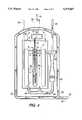
- FIGS. 6A and 6Bwhich best illustrates the invention, show a cross-sectional view of three close packed generators enclosed in a horizontally disposed pressure vessel having two ends, where there is a purge gas volume between the generators and the pressure housing, with flow of purge gas shown where 6A is an end view and 6B is a side view;
- FIG. 7shows an exploded three dimensional view of a four module, transportable, low, center of gravity generator
- FIG. 8shows one embodiment of a 300 MW integrated coal gasification/fuel cell-steam turbine power plant, utilizing a plurality of fuel cell generators, such as shown in FIG. 7;
- FIG. 9shows one specific embodiment of an SOFC- combustion turbine configuration
- FIG. 10shows one embodiment of a 20 MW liquified natural gas fueled fuel cell-steam turbine; all electric power plant utilizing a plurality of fuel cell generators, such as shown in FIG. 7.
- the fuel cells used inside the generator apparatus of this inventioncan be solid oxide electrolyte or molten carbonate fuel cells of any type or configuration.
- tubular, solid oxide electrolyte fuel cellswill be discussed as an exemplary type useful in this invention, and the description herein-after will generally relate to that type, which shall in no way be considered limiting as to the scope of the invention.
- Solid oxide electrolyte fuel cellsare highly efficient devices that convert chemical energy into electricity. They operate at atmospheric or elevated pressures at a temperature of approximately 1000° C. to produce electricity using a variety of fossil fuels such as coal derived fuel gas, natural gas, or distillate fuel.
- the temperature of the exhaust gases from the cellsis between 500° C. to 850° C., a temperature which is attractive for cogeneration applications or for use in bottoming cycles for all-electric central station power plants.
- An operating SOFCreadily conducts oxygen ions from an "air" electrode (electrode which air or oxidant contacts-cathode), where they are formed, through a solid electrolyte to a "fuel” electrode (electrode which fuel contacts-anode). There they react with carbon monoxide (CO) and hydrogen (H 2 ) contained in the fuel gas to deliver electrons and produce electricity.
- the tubular SOFCfeatures a porous air electrode made of doped lanthanum manganite.
- a gas-tight electrolyte of yttria-stabilized zirconiacovers the air electrode, except in a strip about 9mm wide along the entire active cell length.
- This strip of exposed air electrodeis covered by a thin, dense, gas tight layer of doped lanthanum chromite.
- This layertermed the cell interconnection, serves as the electric contacting area to an adjacent cell or to a power contact.
- the fuel electrodeis a nickel-zirconia cermet and covers the electrolyte surface except in the vicinity of the interconnection.
- gaseous oxidanttypically air is introduced into the fuel cell, generally through an air feed tube.
- the airdischarged near the closed end of the cell, flows through the annular space formed by the cell and its coaxial feed tube.
- Gaseous fuelflows on the outside of the cell.
- 85% of the fuelis electrochemically utilized (reacted) in the active fuel cell section.
- the gas-impervious electrolytedoes not allow nitrogen to pass from the air side to the fuel side, hence the fuel is oxidized in a nitrogen free environment, averting the formation of NOx.
- the remaining fuelis reacted with the air stream exiting the cell, thereby providing additional useful heat.
- Reformation of natural gas and other fuels containing hydrocarbonscan be accomplished, if desired, externally or within the generator. Incoming fuel can be reformed to H 2 and CO within the generator, eliminating the need for an external reformer. All the gas flows and reactions are controlled within the generator apparatus.
- the module housing 18can contain one or more modules with any associated recirculation plenums and pre-reformer assemblies.
- the module housingmust withstand fuel cell operating temperatures of 800° C. to 1100° C. and must be made of a material, generally metal, capable of withstanding temperatures over 600° C., such as iron, steel, stainless steel, or nickel alloy.
- the housing 18is shown as a rounded off square, but it can be other configurations.
- Attachment meanssuch as flanged connections,are shown at the top of the housing 18 to bolt or otherwise attach an exhaust gas manifold (not shown).
- oxidant from oxidant inlet lines 20can be fed into integral, cooling ducts 22 distributed along the housing walls 24. Interior thermal insulation 26 is also shown. The arrows show the direction of oxidant or other cooling gas. Modules 10 and 12 would fit inside the housing 18 where shown.
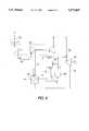
- FIG. 3is a cross section of the front of the fuel cell assembly modules and pre-reformers of FIG. 1 along line 3--3, showing fuel cell bundles 34 and FIG. 4 is a gas flow schematic. Both will be referred to in describing the fuel cell stack, or assembly, operation.
- Each bundlecontains a plurality of interconnected fuel cells 36, here shown as of the tubular SOFC type, with electrodes and sandwiched electrolyte.
- Fuelwould enter fuel inlet piping 38 and pass, preferably to one or more ejectors 40, where recirculation gases may inject-mix with feed fuel, to provide a stream useful in the prereforming section 42, where it is at least partially reformed, and to otherwise provide optimal operating conditions.
- the fuel stream 44then exits pre-reformer 42 and passes through a fuel plenum 46 and into fuel supply lines which transfer or pass at least partly reformed fuel to the outside of fuel cells 36, as shown in FIG. 3 and FIG. 4, where the fuel reacts along the elongated fuel electrode surface on the exterior of the tubular fuel cells 36.
- the fuelcan be more complete reformed within the fuel bundles.
- oxidantenters air manifold 48, through oxidant inlet lines 20, as oxidant stream 50, passing upward, possibly through cooling ducts, to a top air distribution plenum 52.
- the oxidant streamthen is transferred and passes downward via individual oxidant feed tubes 51, shown in FIG. 4 into the bottom interior of each fuel cell 36, where, as is well known in the art, the oxidant reverses flow and passes in the annular space between the oxidant feed tube and the interior air electrode, where it reacts along the air electrode interior surface.
- the reacted oxidantfinally enters a combustion chamber section 54 as spent oxidant.
- the spent oxidantthen combusts with spent fuel, and some remaining unreacted feed fuel, to provide exhaust gas 56, which flows to an exhaust manifold 60, shown in FIG. 3. Part of the spent fuel may also be recirculated to the ejector 40, as shown in FIG. 4.
- the exhaust gas 56passes through exhaust ducts 58 into the exhaust gas manifold 60.
- a power lead 84is also shown in FIG. 4. Further details on these flow patterns as well as use of an ejector system can be found in U.S. Pat. No. 5,169,730 (Reichnet).
- Flame managementcan consist of a series of sensors and interlocks which prevent the occurrence of explosive conditions.
- the management of unreacted fuel in the volume, or space, 62becomes even more critical when an array of electrically connected generators are used to provide a horizontally disposed power block 68, as shown in FIG. 5.
- the general approach of this inventionis to control unwanted, excess, unreacted fuel in the volume 62 outside the module housing, or canister, around the fuel cell modules.
- This approachis to enclose the generator fuel cell stack modules within a high strength, low temperature pressure vessel 64 for pressure containment, and provide gas purge flow within the pressure vessel, in the purge gas volume, or space, 62, to prevent the accumulation of combustible gas.
- the module housing, or canister, 18 around the cell stackseparates feed fuel from the purge gas.
- This inventionalso creates conditions within the pressure vessel 64, such that, if fuel leaks into the purge gas it will ignite locally instead of accumulating to form an explosive mixture, and interlocks the entire system to prevent pressurization unless the above conditions have been met. Then, the purge gas is monitored for the presence of combustible gas, and the fuel system is interlocked to interrupt fuel flow if combustible gas is detected.
- FIG. 6shows SOFC modules within the module housing 18 surrounded by thermal insulation 66 (FIG. 6A end view, partially shown) and contained within the pressure vessel 64.
- the insulation 66would contain a great many minute passageways within its bulk volume where combustible gas might accumulate.
- Fuel, Fenters through, for example, a fuel inlet solenoid valve, and piping, and is directed inside of the module housing 18.
- a catalytic material 68 effective to ignite fuel, such as platinum wire,can surround the fuel line, 70 between the vessel wall and the module housing, a possible area for fuel leakage. This catalyst would serve to ignite locally any leaking fuel.
- Process or oxidant air, Ois supplied to the inside of the SOFC's through, for example, a flow sensor, and air feed tubes as described previously.
- a portion of the fuel and process airis combined electrochemically within the SOFC's to produce DC current, heat, and fuel oxidation products.
- the unconsumed fuelis burned in air in the combustion chamber above the cells.
- Purge gas, Pflows outside of the module housing, entering, for example, through flow sensors from, in one embodiment, one end/end cap of the pressure vessel.
- power lines 84are located at one end cap of the pressure vessel and all gas inlets and exits at the other end cap.
- the purge gas Pcombines with the combustion chamber exhaust at the top of the module housing and flows out of the pressure vessel through exhaust pipes 72 and, for example, a pressure control valve.
- Thermocouples, or other heat measuring devices, 74(FIG. 6A, only one shown) are attached to the module housing and/or pressure vessel to measure wall temperatures.
- the thermocouples 74are electrically interlocked/connected to a fuel inlet valve (not shown) and to an exhaust gas pressure control valve (not shown) such that fuel flow and pressurization cannot be initiated unless the module housing temperature is up to about 520° C., the autoignition fuel temperature.
- Sample tubes or combustible gas sensors, or other gas composition measuring devices, 76(FIG.
- 6Aonly one shown
- These tubes or sensorsare eleectrically interlocked/connected to a fuel inlet valve so that if the amount of unreacted fuel gas in the purge gas constitutes a combustible mixture, the fuel inlet flow is shut off.
- Flow sensorsare located in the purge air entry line 80 and 80' and are electrically interlocked to the fuel supply valve such that the fuel inlet flow will be shut off (or cannot be initiated) unless the purge air is flowing in an appropriate amount.
- the exhaust gas pressure control valvewill be electrically interlocked to the thermocouples and the purge air flow sensors, such that, the system cannot be pressurized if the purge air is not flowing and/or the module housing temperature is below the autoignition temperature of about 520° C.
- the electrical interlockswhich are effective to deactivate/close selected valves and the like by any electrical control means, prevent pressurization until the module housing temperature has reached the autoignition temperature of the fuel, ensure that if an undetected combustible gas mixture exists prior to startup and is ignited when the module housing temperature reaches the autoignition temperature, the resulting deflagration explosion will occur at or near 1 atmosphere.
- the maximum overpressurecan be expected to be about 8 atmospheres, which is less than the vessel design pressure of 10 atmospheres to 20 atmospheres.
- thermal insulation 66is usually required between the inner canister, that is, the module housing 18 and the pressure vessel wall 64 to prevent high temperatures at the pressure vessel wall.
- thermal insulation 66is usually required between the inner canister, that is, the module housing 18 and the pressure vessel wall 64 to prevent high temperatures at the pressure vessel wall.
- pressure vessel wall temperaturesbetween 25° C. and 150° C. are achievable, so that the pressure vessel can be constructed of carbon steel, which is a relatively inexpensive material.
- the fuel cell generator apparatus shown in FIG. 6Bpasses feed oxidant gas, O (dotted line), through pressure vessel 64 at, for example, oxidant pipe 78, while fuel, such as feed natural gas, F (dotted line), passes through pressure vessel 64 at, for example, fuel pipe 70.
- Fuelsuch as feed natural gas, F (dotted line)
- Purge gasany gas effective to delete fuel and provide a noncombustible mixture, air, or an inert gas such as argon, nitrogen, or the like, P (dotted line) passes into pressure vessel 64, at, for example, one or more purge gas pipes 80 and 80'.
- exhaust gasdesignated by flow arrows 82 (solid lines), passes out of pressure vessel 64, at for example, one or more exhaust pipes 72 and 72' (which are shown on the same horizontal plane as fuel entry 70).
- Fuel, F, oxidant, O, and purge gas, Pwill all be pressurized over 28.5 psi. usually between 28.5 psi. (2.0 kg/cm 2 ) and 294 psi. (20.7 kg/cm 2 ), preferably between 73.5 psi (5.18 kg/cm 2 ) and 220.5 psi (15.54 kg/cm 2 ).
- the purge gas, Ppasses into the purge gas volume 62 and circulates around the fuel cell stack modules, such as 10, 12, 13 and 15, between the module housings 18 and the pressure vessel 64. This circulation of purge gas will dilute any unreacted feed fuel which might have migrated/leaked from the modules. The purge gas, with any unreacted feed fuel will pass out of the pressure vessel.
- One means to exit the purge gas, Pis by allowing it to deliberately leak into the exhaust gas manifold 60 through a loose seal 61 between the manifold 60 and the top of module 18, best shown in FIG. 3, and exit with the exhaust gas 82 through one or more pipes 72 and 72.
- line 80may be used as a purge gas inlet and line 80' used as a purge/leaked fuel gas outlet, where a pump for gas in and a pump for gas out would insure effective circulation of the purge gas. Exit through tile manifold 60 is preferred.
- the flow rate of the purge gas, Pwill be in an amount effective to prevent an explosive mixture of purge gas and fuel gas, and may vary depending on purge gas volume.
- the flow rate of the purge gasshould be from about 1 vol.% to about 5 vol.% of the feed oxidant gas flow rate. While many factors are involved in the determination of a maximum allowable fuel leak, unreacted fuel in the purge gas should be kept below about 1000 ppm (parts per million), about 20% of the lower explosive limit.
- the module housing 18, located between the SOFC;s and the thermal insulation,is a container, such that, even though not of completely sealed design, fuel is constrained to remain inside and purge gas outside.
- the pressure difference across the module housing wallis small, which minimizes mechanical loads on the wall and fuel leakage flow rates in the event of module housing leaks.
- the pressure difference across the module housing 18is also positive (higher pressure inside than outside) to insure that any gas leakage is outward.
- the module housing operating temperaturewill be greater than the autoignition temperature of the fuel gas (about 520° C. for hydrogen), thus, any fuel leaking from the module housing into the purge air will spontaneously ignite locally, preventing the accumulation of an explosive mixture inside of the pressure vessel.
- the pressure difference across the loose seal 61is such that exhaust gas from combustion chamber 54, shown in FIG. 3, flows into exhaust gas manifold 60 and exits through appropriate exits 72 and 72', and if the seal 61 between the module housing 18 and manifold 60 is appropriately loose, purge gas from purge gas volume 62 will pass into the manifold 60 and also out exits 72 and 72'.
- FIG. 7illustrates the transportable modular design of an assembled multimodule fuel cell generator apparatus.
- the pressure vessel 64 lengthcan be varied to accommodate a number of 575 kW fuel cell modules of about 2,500 fuel cells per module.
- the four module apparatus shownprovide a 2.3 MW generator.
- the center of gravitymay be below the horizontal axis 98 of the pressure vessel, providing an easily transportable assembly.
- the surface 99can be that of a transport vehicle, or concrete or the like at a final destination.
- the SOFC generator apparatus of this inventionhas been designed and configured to be compatible with small gas turbine units to provide a combined plant size suitable for distributed generation applications.
- An initial configurationprovides for 1.7 MW of SOFC power, targeting an initial demonstration plant application that combines with a 1.4 MW gas turbine to provide an overall net 3 MW plant capability.
- the SOFC generatoris being designed to operate at a pressure of 10 atmospheres, which provides for improved fuel cell performance when compared with atmospheric units.
- the 1.7 MW generatorconsists of three modules, each producing about 575 kW, contained within a common vessel. The use of a common vessel eliminates the need for most of the high pressure piping that would be required for handling the hot air and exhaust streams from individual pressurized submodules.
- Each modulecontains about 2,500 fuel cells arranged in two "substacks" of 1250 cells.
- the moduleuses a gas recirculation loop that provides water for the reforming reactions, and is shared between the two substacks.
- Each modulehas its own power leads and insulation, and is contained within a module housing or canister, that prevents the loss of fuel gas from the stack.
- the submodulesmay be connected electrically in a variety of ways. By creating two parallel paths, each of which has one half of each submodule connected in series, a terminal voltage of about 835 volts and current of about 2075 amps is obtained.
- Individual module dimensionsare 2.9 meters in width, 2.4 meters long, and 2.9 meters high.
- common headersare provided for supplying each module with process air, fuel, and purge gas and removing the exhaust stream and circulated purge gas.
- the overall pressure vessel dimensions, for a three module unit,are 4.2 meters in diameter, and 9.3 meters in length. Penetrations of the pressure vessel are made at the two ends and provide access to the purge gas and to the air and exhaust piping that is connected to the turbine unit.
- FIG. 8depicts a 300 MW, integrated coal gasification/fuel cell steam turbine power plant 100.
- Coal gasification unit 102, air separation (oxygen) plant 104, DC/AC conversion and electrical switch gear and power conditioning unit 106are shown, along with five, 50,000-ton coal storage silos 108.
- the fuel feed from the coal gasification unitscan operate SOFC apparatus 110, described previously, which in turn are associated with a heat recovery steam turbine 112 and heat recovery steam generator 114.
- a compressorcould compress ambient air, which could be supplied to the fuel cells, and the purge volume after being preheated by a recuperator.
- the hot gas from the power blockscould be pumped at high pressure to a combustor, producing further heated hot gas that could be expanded in a turbine to produce power.
- the turbinecould in turn run a compressor for pressurizing the oxidant stream, as in U.S. Pat. No. 3,972,731 (Bloomfield et al.).
- the hot gas from the SOFC'scould be directed to a turbine by way of a topping combustor that is supplied with fuel, to produce a still further heated hot gas that is then passed to and expanded in a turbine apparatus as in U.S. Pat. No. 5,413,879 (Domeracki et al.).
- the major components of the systemwould be a compressor, a turbine, a rotor by which the turbine drives the compressor as well as an electrical generator, a fuel pre-heater, an air pre-heater, a fuel desulfurizer, a solid oxide fuel cell generator with a combustion chamber, a topping combustor and an exhaust stack.
- the compressorwhich includes rows of stationary vanes and rotating blades, inducts ambient air and produces compressed air.
- the compressed airis subsequently heated by the air pre-heater.
- the air preheaterwhich may be of the tube and shell type, has heat transfer surfaces that allow heat to be transferred from the turbine exhaust gas discharged by the fuel pre-heater, to the compressed air, thereby producing heated compressed air.
- the compressed aircan be heated into approximately the 500° C.-600° C.
- the heated compressed airis then directed to the SOFC generator and purge volume within the pressure vessel surrounding the SOFC's.
- Gaseous fuelwhich may be natural gas or a coal derived fuel gas, is driven by a pump through the fuel pre-heater.
- the fuel pre-heaterwhich may be of the finned tube type, has heat transfer surfaces that allow heat to be transferred from the exhaust gas discharged by the turbine to the fuel, thereby producing heated fuel.
- the fuelcan be heated to approximately 400° C.
- the heated fuelis then directed to a desulfurizer, which may comprise a vessel containing a bed of sulfur sorbent through which the fuel flows.
- the fuel exiting from the desulfurizerpreferably, has less than 0.1 ppm of sulfur.
- Oxidantsuch as air, O
- Fuel Fpasses through a desulferizer 132 and then, along with oxidant 0, is fed into the fuel cell generator apparatus 134.
- Pressurized oxidantalso passes as purge gas to the purge volume between the SOFC's and their pressure vessel. Exhaust gas from fuel cell generator apparatus 134 then passes onto the turbine of the compressor/turbne system 122.
- FIGS. 8 and 9have been generally described using SOFC, other types of fuel cell, could be used in such systems, as described previously. These are only one of the designs that could use the fuel cell generator apparatus of this invention. They are also applicable to SOFC cogeneration systems utilizing steam from boilers; liquified natural gas fueled SOFC, all electric power plants; repowering of existing fossil fuel power plants; and navel ship electrical propulsion.
- FIG. 10illustrates a design for a 20 MW liquified natural gas fueled SOFC all-electric power plant.
- the key featuresinclude a plurality of the modular fuel cell generator apparatus 140 described previously, a heat recovery system, steam turbine system 142 and a power conditioning system.
- the fuel cell generator apparatus of this inventioncan also be used very advantageously with a small combustion turbine system to form a 3 MW plant.
- the plantwould be well suited for the cogeneration, power quality and distributed power markets and is suitable for siting within a light industrial one.
- the power systemis based on a combustion turbine that is intercooled, recuperated, and reheated.
- the intercooled, recuperated gas turbine enginewould provide pressurized air to the fuel cells, and the hot exhaust gas from the fuel cells would be expanded through a radial inflow power turbine.
- a single stage air-to-air intercoolerwould be used to reduce compressor work and to increase the efficiency of the recuperator.
- the SOFC generator apparatuswould be placed ahead of the high-pressure combustor, and the hot SOFC exhaust would provide some or all of the combustor's oxidant stream.
- the cyclewould be equipped with a desulfurizer system to process the SOFC natural gas fuel.
- the SOFC systemwould be sized, and the operating point selected, such that SOFC heat provides sufficient inlet temperature at the compressor turbine inlet to eliminate the need for fuel flow to the combustor.
Landscapes
- Life Sciences & Earth Sciences (AREA)
- Engineering & Computer Science (AREA)
- Manufacturing & Machinery (AREA)
- Sustainable Development (AREA)
- Sustainable Energy (AREA)
- Chemical & Material Sciences (AREA)
- Chemical Kinetics & Catalysis (AREA)
- Electrochemistry (AREA)
- General Chemical & Material Sciences (AREA)
- Fuel Cell (AREA)
Abstract
Description
Claims (25)
Priority Applications (3)
| Application Number | Priority Date | Filing Date | Title |
|---|---|---|---|
| US08/594,214US5573867A (en) | 1996-01-31 | 1996-01-31 | Purge gas protected transportable pressurized fuel cell modules and their operation in a power plant |
| PCT/US1997/000055WO1997028573A1 (en) | 1996-01-31 | 1997-01-09 | Purge gas protected transportable pressurized fuel cell modules and their operation in a power plant |
| AU13579/97AAU1357997A (en) | 1996-01-31 | 1997-01-09 | Purge gas protected transportable pressurized fuel cell modules and their operation in a power plant |
Applications Claiming Priority (1)
| Application Number | Priority Date | Filing Date | Title |
|---|---|---|---|
| US08/594,214US5573867A (en) | 1996-01-31 | 1996-01-31 | Purge gas protected transportable pressurized fuel cell modules and their operation in a power plant |
Publications (1)
| Publication Number | Publication Date |
|---|---|
| US5573867Atrue US5573867A (en) | 1996-11-12 |
Family
ID=24378001
Family Applications (1)
| Application Number | Title | Priority Date | Filing Date |
|---|---|---|---|
| US08/594,214Expired - LifetimeUS5573867A (en) | 1996-01-31 | 1996-01-31 | Purge gas protected transportable pressurized fuel cell modules and their operation in a power plant |
Country Status (3)
| Country | Link |
|---|---|
| US (1) | US5573867A (en) |
| AU (1) | AU1357997A (en) |
| WO (1) | WO1997028573A1 (en) |
Cited By (154)
| Publication number | Priority date | Publication date | Assignee | Title |
|---|---|---|---|---|
| WO1997033333A1 (en)* | 1996-03-08 | 1997-09-12 | Westinghouse Electric Corporation | Solid oxide fuel cell generator with removable modular fuel cell stack configurations |
| US5750278A (en)* | 1995-08-10 | 1998-05-12 | Westinghouse Electric Corporation | Self-cooling mono-container fuel cell generators and power plants using an array of such generators |
| WO1998029918A1 (en)* | 1996-12-31 | 1998-07-09 | Ztek Corporation | Pressurized, integrated electrochemical converter energy system |
| WO1998029917A1 (en)* | 1996-12-26 | 1998-07-09 | Westinghouse Electric Corporation | Self-cooling mono-container fuel cell generators and power plants using an array of such generators |
| US6033794A (en)* | 1997-12-10 | 2000-03-07 | The United States Of America As Represented By The United States Department Of Energy | Multi-stage fuel cell system method and apparatus |
| US6074771A (en)* | 1998-02-06 | 2000-06-13 | Igr Enterprises, Inc. | Ceramic composite electrolytic device and method for manufacture thereof |
| US6114058A (en)* | 1998-05-26 | 2000-09-05 | Siemens Westinghouse Power Corporation | Iron aluminide alloy container for solid oxide fuel cells |
| WO2001006589A1 (en)* | 1999-07-19 | 2001-01-25 | Siemens Westinghouse Power Corporation | Single module pressurized fuel cell turbine generator system |
| US6221522B1 (en) | 1999-09-10 | 2001-04-24 | Siemens Westinghouse Power Corporation | Open end protection for solid oxide fuel cells |
| US6238817B1 (en)* | 1999-02-03 | 2001-05-29 | International Fuel Cells, Llc | Gas injection system for treating a fuel cell stack assembly |
| US6316134B1 (en)* | 1999-09-13 | 2001-11-13 | Ballard Generation Systems, Inc. | Fuel cell electric power generation system |
| US6329093B1 (en)* | 1998-08-20 | 2001-12-11 | Matsushita Electric Industrial Co., Ltd. | Polymer electrolyte fuel cell stack |
| US6444342B1 (en) | 2000-08-18 | 2002-09-03 | Siemens Westinghouse Power Corporation | Air feed tube support system for a solid oxide fuel cell generator |
| WO2002091510A1 (en)* | 2001-05-03 | 2002-11-14 | General Motors Corporation | Electronic by-pass of fuel cell cathode gas to combustor |
| US6492048B1 (en) | 2000-08-10 | 2002-12-10 | Siemens Westinghouse Power Corporation | Segregated exhaust fuel cell generator |
| US20030025397A1 (en)* | 2001-02-13 | 2003-02-06 | Young Douglas Gibbons | System for providing assured power to a critical load |
| US20030054209A1 (en)* | 2001-09-17 | 2003-03-20 | Siemens Westinghouse Power Corporation | Standard package design for both atmospheric and pressurized SOFC power generation system |
| WO2002078103A3 (en)* | 2001-03-15 | 2003-03-27 | Int Fuel Cells Llc | Control of multiple fuel cell power plant |
| US6572996B1 (en) | 2000-08-10 | 2003-06-03 | Siemens Westinghouse Power Corporation | Electrochemical fuel depletion means for fuel cell generators |
| NL1019397C2 (en)* | 2001-11-19 | 2003-06-13 | Willem Jan Oosterkamp | Fuel cell stack in a pressure vessel. |
| US20030134161A1 (en)* | 2001-09-20 | 2003-07-17 | Gore Makarand P. | Protective container with preventative agent therein |
| US6608463B1 (en)* | 2002-06-24 | 2003-08-19 | Delphi Technologies, Inc. | Solid-oxide fuel cell system having an integrated air supply system |
| US20030157386A1 (en)* | 2002-02-20 | 2003-08-21 | Ion America Corporation | Load matched power generation system including a solid oxide fuel cell and a heat pump and an optional turbine |
| US6610434B1 (en)* | 2000-08-10 | 2003-08-26 | Siemens Westinghouse Power Corporation | Segregated exhaust SOFC generator with high fuel utilization capability |
| US6641946B2 (en) | 2001-02-15 | 2003-11-04 | Siemens Westinghouse Power Corporation | Fuel dissipater for pressurized fuel cell generators |
| US6656623B2 (en) | 2001-02-15 | 2003-12-02 | Siemens Westinghouse Power Corporation | Low-cost atmospheric SOFC power generation system |
| US6689499B2 (en) | 2001-09-17 | 2004-02-10 | Siemens Westinghouse Power Corporation | Pressurized solid oxide fuel cell integral air accumular containment |
| US20040043265A1 (en)* | 2002-09-04 | 2004-03-04 | General Electric Company | Staged fuel cell with intercooling |
| US20040062973A1 (en)* | 2002-10-01 | 2004-04-01 | Agnew Gerard D. | Solid oxide fuel cell system |
| US20040081859A1 (en)* | 2002-10-23 | 2004-04-29 | Ion America | Solid oxide regenerative fuel cell |
| US20040086765A1 (en)* | 2002-06-21 | 2004-05-06 | Florence Stephen | Fuel cell insulating heat exchanger |
| US20040091754A1 (en)* | 2000-09-26 | 2004-05-13 | Willi Bette | Method for operating a fuel cell arrangement and fuel cell arrangement for carrying out the method |
| US20040106019A1 (en)* | 2002-07-31 | 2004-06-03 | Wojtek Halliop | Fuel cell system with degradation protected anode |
| US20040150366A1 (en)* | 2003-01-30 | 2004-08-05 | Ferrall Joseph F | Turbocharged Fuel Cell Systems For Producing Electric Power |
| EP1463135A1 (en) | 2003-03-27 | 2004-09-29 | Nissan Motor Co., Ltd. | Fuel cell system |
| US20040191597A1 (en)* | 2003-03-24 | 2004-09-30 | Ion America Corporation | Solid oxide regenerative fuel cell with selective anode tail gas circulation |
| US20040191595A1 (en)* | 2003-03-24 | 2004-09-30 | Ion America Corporation | SORFC system and method with an exothermic net electrolysis reaction |
| US20040202914A1 (en)* | 2003-04-09 | 2004-10-14 | Ion America Corporation | Co-production of hydrogen and electricity in a high temperature electrochemical system |
| US20050048334A1 (en)* | 2003-09-03 | 2005-03-03 | Ion America Corporation | Combined energy storage and fuel generation with reversible fuel cells |
| US20050053812A1 (en)* | 2003-09-10 | 2005-03-10 | Ion America Corporation | SORFC system with non-noble metal electrode compositions |
| US20050123808A1 (en)* | 2003-12-05 | 2005-06-09 | Siemens Westinghouse Power Corporation | Integral air preheater and start-up heating means for solid oxide fuel cell power generators |
| US20050164051A1 (en)* | 2004-01-22 | 2005-07-28 | Ion America Corporation | High temperature fuel cell system and method of operating same |
| US20050208363A1 (en)* | 2004-03-19 | 2005-09-22 | Taylor Owen S | Multi-function solid oxide fuel cell bundle and method of making the same |
| US20050266288A1 (en)* | 2004-05-27 | 2005-12-01 | Siemens Westinghouse Power Corporation | Flexible ceramic gasket for SOFC generator |
| US20050271917A1 (en)* | 2004-05-28 | 2005-12-08 | Airbus Deutschland Gmbh | Electrochemical reactor for aircraft and method for operating the electrochemical reactor |
| EP1231660A3 (en)* | 2001-02-13 | 2006-01-04 | Delphi Technologies, Inc. | Fuel cell system hot zone pressure regulator |
| WO2005036688A3 (en)* | 2003-10-09 | 2006-01-12 | Rag Ag | Fuel cell used in underground mining |
| US20060029849A1 (en)* | 2004-07-19 | 2006-02-09 | Dirk Metzler | System for water reclamation from an exhaust gas flow of a fuel cell of an aircraft |
| US20060105207A1 (en)* | 2004-11-18 | 2006-05-18 | Siemens Westinghouse Power Corporation | Recuperated atmospheric SOFC/gas turbine hybrid cycle |
| US20060134485A1 (en)* | 2004-12-22 | 2006-06-22 | Michio Horiuchi | Fuel battery |
| US20060147771A1 (en)* | 2005-01-04 | 2006-07-06 | Ion America Corporation | Fuel cell system with independent reformer temperature control |
| US20060151734A1 (en)* | 2002-11-29 | 2006-07-13 | Keihin Corporation | Solenoid valve for fuel cell |
| US7094490B2 (en) | 2002-05-13 | 2006-08-22 | Polyfuel, Inc. | Ion conductive block copolymers |
| US20060222929A1 (en)* | 2005-04-01 | 2006-10-05 | Ion America Corporation | Reduction of SOFC anodes to extend stack lifetime |
| US20060228598A1 (en)* | 2005-04-07 | 2006-10-12 | Swaminathan Venkataraman | Fuel cell system with thermally integrated combustor and corrugated foil reformer |
| US20060251934A1 (en)* | 2005-05-09 | 2006-11-09 | Ion America Corporation | High temperature fuel cell system with integrated heat exchanger network |
| US20060251939A1 (en)* | 2005-05-09 | 2006-11-09 | Bandhauer Todd M | High temperature fuel cell system with integrated heat exchanger network |
| US20060251940A1 (en)* | 2005-05-09 | 2006-11-09 | Bandhauer Todd M | High temperature fuel cell system with integrated heat exchanger network |
| US20060257696A1 (en)* | 2005-05-10 | 2006-11-16 | Ion America Corporation | Increasing thermal dissipation of fuel cell stacks under partial electrical load |
| US20070017368A1 (en)* | 2005-07-25 | 2007-01-25 | Ion America Corporation | Gas separation method and apparatus using partial pressure swing adsorption |
| US20070017367A1 (en)* | 2005-07-25 | 2007-01-25 | Ion America Corporation | Partial pressure swing adsorption system for providing hydrogen to a vehicle fuel cell |
| US20070017369A1 (en)* | 2005-07-25 | 2007-01-25 | Ion America Corporation | Fuel cell anode exhaust fuel recovery by adsorption |
| US20070048559A1 (en)* | 2005-09-01 | 2007-03-01 | Jon Beasley | Air reservoir to dilute hydrogen emissions |
| US7202001B2 (en) | 2002-05-13 | 2007-04-10 | Polyfuel, Inc. | Sulfonated copolymer |
| USRE39710E1 (en) | 2001-02-13 | 2007-07-03 | Utc Fuel Cells, Llc | System for providing assured power to a critical load |
| US20070178338A1 (en)* | 2005-07-25 | 2007-08-02 | Ion America Corporation | Fuel cell system with electrochemical anode exhaust recycling |
| US20070196702A1 (en)* | 2003-04-09 | 2007-08-23 | Bloom Energy Corporation | Low pressure hydrogen fueled vehicle and method of operating same |
| US20070231631A1 (en)* | 2006-04-03 | 2007-10-04 | Bloom Energy Corporation | Hybrid reformer for fuel flexibility |
| US20070231635A1 (en)* | 2006-04-03 | 2007-10-04 | Bloom Energy Corporation | Fuel cell system operated on liquid fuels |
| US20080057359A1 (en)* | 2006-09-06 | 2008-03-06 | Bloom Energy Corporation | Flexible fuel cell system configuration to handle multiple fuels |
| US20080075985A1 (en)* | 2006-09-21 | 2008-03-27 | Ion America Corporation | Adaptive purge control to prevent electrode redox cycles in fuel cell systems |
| US20080076006A1 (en)* | 2006-09-25 | 2008-03-27 | Ion America Corporation | High utilization stack |
| WO2008034987A1 (en)* | 2006-09-21 | 2008-03-27 | Commissariat A L'energie Atomique | Solid oxide fuel cell comprising a thermal exchanger |
| US7354679B2 (en) | 2002-05-13 | 2008-04-08 | Polyfuel, Inc. | Ion conductive random copolymers |
| US20080096073A1 (en)* | 2006-10-23 | 2008-04-24 | Bloom Energy Corporation | Dual function heat exchanger for start-up humidification and facility heating in SOFC system |
| US20080107946A1 (en)* | 2006-11-08 | 2008-05-08 | Akira Gunji | Fuel cells power generation system |
| US20080113246A1 (en)* | 2005-01-03 | 2008-05-15 | Wartsila Finland Oy | Arrangement And Method In A Fuel Cell Apparatus |
| US20080152959A1 (en)* | 2006-12-20 | 2008-06-26 | Bloom Energy Corporation | Methods for fuel cell system optimization |
| WO2008099575A1 (en)* | 2007-02-09 | 2008-08-21 | Nissan Motor Co., Ltd. | Fuel cell power generation system and operation method thereof |
| US20080241612A1 (en)* | 2007-03-30 | 2008-10-02 | Bloom Energy Corporation | Fuel cell system with one hundred percent fuel utilization |
| US20080241638A1 (en)* | 2007-03-30 | 2008-10-02 | Bloom Energy Corporation | SOFC system producing reduced atmospheric carbon dioxide using a molten carbonated carbon dioxide pump |
| US20090130501A1 (en)* | 2007-11-19 | 2009-05-21 | Enymotion Gmbh | Fuel cell system and method for operating the same |
| US20090155660A1 (en)* | 2007-12-14 | 2009-06-18 | Korea Institute Of Energy Research | Tubular solid oxide fuel cells |
| US7575822B2 (en) | 2003-04-09 | 2009-08-18 | Bloom Energy Corporation | Method of optimizing operating efficiency of fuel cells |
| US7659022B2 (en) | 2006-08-14 | 2010-02-09 | Modine Manufacturing Company | Integrated solid oxide fuel cell and fuel processor |
| US20100047637A1 (en)* | 2008-07-23 | 2010-02-25 | Bloom Energy Corporation | Operation of fuel cell systems with reduced carbon formation and anode leading edge damage |
| EP1380061A4 (en)* | 2000-10-30 | 2010-04-07 | Ztek Corp | Multi-function energy system operable as a fuel cell, reformer, or thermal plant |
| US20100139465A1 (en)* | 2008-12-08 | 2010-06-10 | Next Vascular, Llc | Micro-Cutting Machine for Forming Cuts in Products |
| US20100183936A1 (en)* | 2009-01-16 | 2010-07-22 | Ford Motor Company | Modular fuel cell power system |
| US20100239924A1 (en)* | 2005-07-25 | 2010-09-23 | Ion America Corporation | Fuel cell system with partial recycling of anode exhaust |
| US20100269540A1 (en)* | 2009-04-24 | 2010-10-28 | Ebara International Corporation | Method to Liquefy Ammonia Gas |
| US7846599B2 (en) | 2007-06-04 | 2010-12-07 | Bloom Energy Corporation | Method for high temperature fuel cell system start up and shutdown |
| US20100310948A1 (en)* | 2009-06-05 | 2010-12-09 | Adaptive Materials, Inc. | Fuel cell system with integrated air handling plate |
| US20110053027A1 (en)* | 2009-09-02 | 2011-03-03 | Bloom Energy Corporation | Multi-Stream Heat Exchanger for a Fuel Cell System |
| WO2011038830A1 (en)* | 2009-09-30 | 2011-04-07 | Daimler Ag | Method for operating a fuel cell system |
| US20110189587A1 (en)* | 2010-02-01 | 2011-08-04 | Adaptive Materials, Inc. | Interconnect Member for Fuel Cell |
| US20110281185A1 (en)* | 2006-01-23 | 2011-11-17 | Bloom Energy Corporation | Modular fuel cell system |
| US8067129B2 (en) | 2007-11-13 | 2011-11-29 | Bloom Energy Corporation | Electrolyte supported cell designed for longer life and higher power |
| US8137855B2 (en) | 2007-07-26 | 2012-03-20 | Bloom Energy Corporation | Hot box design with a multi-stream heat exchanger and single air control |
| US8241801B2 (en) | 2006-08-14 | 2012-08-14 | Modine Manufacturing Company | Integrated solid oxide fuel cell and fuel processor |
| US8288041B2 (en) | 2008-02-19 | 2012-10-16 | Bloom Energy Corporation | Fuel cell system containing anode tail gas oxidizer and hybrid heat exchanger/reformer |
| US8340886B2 (en) | 2011-03-07 | 2012-12-25 | General Electric Company | System and method for transitioning between fuel supplies for a combustion system |
| US8440362B2 (en) | 2010-09-24 | 2013-05-14 | Bloom Energy Corporation | Fuel cell mechanical components |
| US20130175805A1 (en)* | 2012-01-11 | 2013-07-11 | George Berntsen | Electrical generation system and method for a hybrid fuel cell power plant |
| US8563180B2 (en) | 2011-01-06 | 2013-10-22 | Bloom Energy Corporation | SOFC hot box components |
| JP2013222592A (en)* | 2012-04-16 | 2013-10-28 | Osaka Gas Co Ltd | Fuel cell device |
| US8580456B2 (en) | 2010-01-26 | 2013-11-12 | Bloom Energy Corporation | Phase stable doped zirconia electrolyte compositions with low degradation |
| US8617763B2 (en) | 2009-08-12 | 2013-12-31 | Bloom Energy Corporation | Internal reforming anode for solid oxide fuel cells |
| US8748056B2 (en) | 2006-10-18 | 2014-06-10 | Bloom Energy Corporation | Anode with remarkable stability under conditions of extreme fuel starvation |
| US8852820B2 (en) | 2007-08-15 | 2014-10-07 | Bloom Energy Corporation | Fuel cell stack module shell with integrated heat exchanger |
| US8968958B2 (en) | 2008-07-08 | 2015-03-03 | Bloom Energy Corporation | Voltage lead jumper connected fuel cell columns |
| US20150263362A1 (en)* | 2014-03-17 | 2015-09-17 | Panasonic Corporation | Fuel cell system |
| US20150270562A1 (en)* | 2014-03-20 | 2015-09-24 | Honda Motor Co., Ltd. | Fuel cell vehicle |
| US9246184B1 (en) | 2007-11-13 | 2016-01-26 | Bloom Energy Corporation | Electrolyte supported cell designed for longer life and higher power |
| EP2991149A1 (en)* | 2014-08-27 | 2016-03-02 | Vaillant GmbH | Hot box of a fuel cell system |
| US20160064752A1 (en)* | 2013-03-28 | 2016-03-03 | Kyocera Corporation | Solid-oxide electrolytic cell, cell stack device and electrolytic module, and electrolytic device |
| US9287572B2 (en) | 2013-10-23 | 2016-03-15 | Bloom Energy Corporation | Pre-reformer for selective reformation of higher hydrocarbons |
| US20160190622A1 (en)* | 2013-03-14 | 2016-06-30 | Battelle Memorial Institute | High power density solid oxide fuel cell steam reforming system and process for electrical generation |
| US9461320B2 (en) | 2014-02-12 | 2016-10-04 | Bloom Energy Corporation | Structure and method for fuel cell system where multiple fuel cells and power electronics feed loads in parallel allowing for integrated electrochemical impedance spectroscopy (EIS) |
| US9515344B2 (en) | 2012-11-20 | 2016-12-06 | Bloom Energy Corporation | Doped scandia stabilized zirconia electrolyte compositions |
| US9620792B2 (en) | 2011-01-03 | 2017-04-11 | Audi Ag | Thermal energy recycling fuel cell arrangement |
| US9755263B2 (en) | 2013-03-15 | 2017-09-05 | Bloom Energy Corporation | Fuel cell mechanical components |
| FR3054377A1 (en)* | 2016-07-25 | 2018-01-26 | Safran Power Units | FUEL CELL WITH VENTILATION SYSTEM |
| CN109314258A (en)* | 2016-06-20 | 2019-02-05 | 京瓷株式会社 | Fuel cell module and fuel cell device |
| US10347930B2 (en) | 2015-03-24 | 2019-07-09 | Bloom Energy Corporation | Perimeter electrolyte reinforcement layer composition for solid oxide fuel cell electrolytes |
| US10361442B2 (en) | 2016-11-08 | 2019-07-23 | Bloom Energy Corporation | SOFC system and method which maintain a reducing anode environment |
| US10593981B2 (en) | 2007-04-13 | 2020-03-17 | Bloom Energy Corporation | Heterogeneous ceramic composite SOFC electrolyte |
| US10615444B2 (en) | 2006-10-18 | 2020-04-07 | Bloom Energy Corporation | Anode with high redox stability |
| US10651496B2 (en) | 2015-03-06 | 2020-05-12 | Bloom Energy Corporation | Modular pad for a fuel cell system |
| US10680251B2 (en) | 2017-08-28 | 2020-06-09 | Bloom Energy Corporation | SOFC including redox-tolerant anode electrode and system including the same |
| US10953203B2 (en) | 2016-07-18 | 2021-03-23 | Scientia Vascular, Llc | Guidewire devices having shapeable polymer tips |
| CN112968201A (en)* | 2021-02-05 | 2021-06-15 | 东莞市爱康电子科技有限公司 | Self-adaptive hot pressing mechanism |
| US11052228B2 (en) | 2016-07-18 | 2021-07-06 | Scientia Vascular, Llc | Guidewire devices having shapeable tips and bypass cuts |
| US11305095B2 (en) | 2018-02-22 | 2022-04-19 | Scientia Vascular, Llc | Microfabricated catheter having an intermediate preferred bending section |
| US11369351B2 (en) | 2017-05-26 | 2022-06-28 | Scientia Vascular, Inc. | Micro-fabricated medical device having a non-helical cut arrangement |
| US11398634B2 (en) | 2018-03-27 | 2022-07-26 | Bloom Energy Corporation | Solid oxide fuel cell system and method of operating the same using peak shaving gas |
| US11406791B2 (en) | 2009-04-03 | 2022-08-09 | Scientia Vascular, Inc. | Micro-fabricated guidewire devices having varying diameters |
| US11452541B2 (en) | 2016-12-22 | 2022-09-27 | Scientia Vascular, Inc. | Intravascular device having a selectively deflectable tip |
| NO20220699A1 (en)* | 2022-06-20 | 2023-12-21 | Corvus Energy AS | Safety and Support System for a Fuel Cell Module |
| US11859820B1 (en) | 2022-11-10 | 2024-01-02 | General Electric Company | Gas turbine combustion section having an integrated fuel cell assembly |
| US11923586B1 (en) | 2022-11-10 | 2024-03-05 | General Electric Company | Gas turbine combustion section having an integrated fuel cell assembly |
| US12011555B2 (en) | 2019-01-15 | 2024-06-18 | Scientia Vascular, Inc. | Guidewire with core centering mechanism |
| US12078350B2 (en) | 2022-11-10 | 2024-09-03 | General Electric Company | Gas turbine combustion section having an integrated fuel cell assembly |
| US12092334B2 (en) | 2021-05-04 | 2024-09-17 | General Electric Company | Integrated fuel cell and engine combustor assembly |
| US12178975B2 (en) | 2020-01-23 | 2024-12-31 | Scientia Vascular, Inc. | Guidewire having enlarged, micro-fabricated distal section |
| US12220538B2 (en) | 2008-12-08 | 2025-02-11 | Scientia Vascular, Inc. | Micro-fabricated intravascular devices having varying diameters |
| US12240613B2 (en) | 2022-11-10 | 2025-03-04 | General Electric Company | Gas turbine combustion section having an integrated fuel cell assembly |
| US12261334B2 (en) | 2023-02-23 | 2025-03-25 | General Electric Company | Gas turbine engine and fuel cell assembly |
| US12266835B2 (en) | 2017-08-28 | 2025-04-01 | Bloom Energy Corporation | SOFC including redox-tolerant anode electrode and method of making the same |
| US12270340B2 (en) | 2023-02-23 | 2025-04-08 | General Electric Company | Gas turbine engine and fuel cell assembly |
| US12296112B2 (en) | 2020-10-05 | 2025-05-13 | Scientia Vascular, Inc. | Microfabricated catheter devices with high axial strength |
| US12343485B2 (en) | 2020-01-23 | 2025-07-01 | Scientia Vascular, Inc. | High torque guidewire device |
| US12364840B2 (en) | 2016-07-29 | 2025-07-22 | Cephea Valve Technologies, Inc. | Mechanical interlock for catheters |
| US12440332B2 (en) | 2021-08-11 | 2025-10-14 | Cephea Valve Technologies, Inc. | Systems and methods for loading and deploying an intravascular device |
Families Citing this family (6)
| Publication number | Priority date | Publication date | Assignee | Title |
|---|---|---|---|---|
| US5968680A (en)* | 1997-09-10 | 1999-10-19 | Alliedsignal, Inc. | Hybrid electrical power system |
| AU5816898A (en)* | 1998-01-08 | 1999-07-26 | Southern California Edison Company | Power generation system utilizing turbine gas generator and fuel cell |
| US20020081471A1 (en)* | 2000-12-22 | 2002-06-27 | Keegan Kevin R. | Fuel cell system incorporating pressure control |
| CN102881923B (en)* | 2011-07-14 | 2015-01-07 | 中国科学院大连化学物理研究所 | Anode-supported tube type solid oxide fuel cell constructed power station |
| AT525484A1 (en)* | 2021-09-21 | 2023-04-15 | Avl List Gmbh | Fuel cell system for generating electricity in stationary operation |
| WO2025142876A1 (en)* | 2023-12-27 | 2025-07-03 | パナソニックIpマネジメント株式会社 | Fuel cell stack and fuel cell unit provided with plurality of said fuel cell stacks |
Citations (7)
| Publication number | Priority date | Publication date | Assignee | Title |
|---|---|---|---|---|
| US3972731A (en)* | 1975-02-12 | 1976-08-03 | United Technologies Corporation | Pressurized fuel cell power plant |
| US4395468A (en)* | 1980-12-22 | 1983-07-26 | Westinghouse Electric Corp. | Fuel cell generator |
| US4476196A (en)* | 1983-10-12 | 1984-10-09 | The United States Of America As Represented By The United States Department Of Energy | Solid oxide fuel cell having monolithic cross flow core and manifolding |
| US4476198A (en)* | 1983-10-12 | 1984-10-09 | The United States Of America As Represented By The United States Department Of Energy | Solid oxide fuel cell having monolithic core |
| US4622275A (en)* | 1984-07-31 | 1986-11-11 | Hitachi, Ltd. | Fuel cell power plant |
| US5169730A (en)* | 1990-07-25 | 1992-12-08 | Westinghouse Electric Corp. | Electrochemical cell apparatus having an exterior fuel mixer nozzle |
| US5413879A (en)* | 1994-02-08 | 1995-05-09 | Westinghouse Electric Corporation | Integrated gas turbine solid oxide fuel cell system |
Family Cites Families (9)
| Publication number | Priority date | Publication date | Assignee | Title |
|---|---|---|---|---|
| JPS59138075A (en)* | 1983-01-26 | 1984-08-08 | Hitachi Ltd | Accommodation equipment of stack type fuel cell |
| JPH0610990B2 (en)* | 1983-11-09 | 1994-02-09 | 株式会社日立製作所 | Fuel cell |
| JPS61104566A (en)* | 1984-10-29 | 1986-05-22 | Toshiba Corp | Fuel cell |
| JPH0665063B2 (en)* | 1986-05-06 | 1994-08-22 | 三洋電機株式会社 | Fuel cell storage container |
| JPS62264564A (en)* | 1986-05-12 | 1987-11-17 | Ishikawajima Harima Heavy Ind Co Ltd | Stacked fuel cell |
| JPS6337573A (en)* | 1986-07-31 | 1988-02-18 | Ishikawajima Harima Heavy Ind Co Ltd | Fuel cell system |
| EP0374636A1 (en)* | 1988-12-20 | 1990-06-27 | Asea Brown Boveri Ag | Process for the conversion of the chemical potential energy of a material into electrical energy by a high-temperature electrochemical process |
| JPH0419967A (en)* | 1990-05-15 | 1992-01-23 | Ishikawajima Harima Heavy Ind Co Ltd | Molten carbonate fuel cell power generating system |
| US5693201A (en)* | 1994-08-08 | 1997-12-02 | Ztek Corporation | Ultra-high efficiency turbine and fuel cell combination |
- 1996
- 1996-01-31USUS08/594,214patent/US5573867A/ennot_activeExpired - Lifetime
- 1997
- 1997-01-09WOPCT/US1997/000055patent/WO1997028573A1/enactiveApplication Filing
- 1997-01-09AUAU13579/97Apatent/AU1357997A/ennot_activeWithdrawn
Patent Citations (7)
| Publication number | Priority date | Publication date | Assignee | Title |
|---|---|---|---|---|
| US3972731A (en)* | 1975-02-12 | 1976-08-03 | United Technologies Corporation | Pressurized fuel cell power plant |
| US4395468A (en)* | 1980-12-22 | 1983-07-26 | Westinghouse Electric Corp. | Fuel cell generator |
| US4476196A (en)* | 1983-10-12 | 1984-10-09 | The United States Of America As Represented By The United States Department Of Energy | Solid oxide fuel cell having monolithic cross flow core and manifolding |
| US4476198A (en)* | 1983-10-12 | 1984-10-09 | The United States Of America As Represented By The United States Department Of Energy | Solid oxide fuel cell having monolithic core |
| US4622275A (en)* | 1984-07-31 | 1986-11-11 | Hitachi, Ltd. | Fuel cell power plant |
| US5169730A (en)* | 1990-07-25 | 1992-12-08 | Westinghouse Electric Corp. | Electrochemical cell apparatus having an exterior fuel mixer nozzle |
| US5413879A (en)* | 1994-02-08 | 1995-05-09 | Westinghouse Electric Corporation | Integrated gas turbine solid oxide fuel cell system |
Non-Patent Citations (6)
| Title |
|---|
| "Fuel Cells Make Their CPI Moves", B. R. Gilbert, et al., Chemical Engineering, Aug., 1995, pp. 92-96. |
| "Molten Carbonate Fuel Cell Demonstrates its Commercial Readiness", S. E. Kuehn, Power Engineering, Mar., 1995, p. 16. |
| "Solid Oxide Fuel Cell", Westinghouse Electric Corporation, Oct., 1992. |
| Fuel Cells Make Their CPI Moves , B. R. Gilbert, et al., Chemical Engineering, Aug., 1995, pp. 92 96.* |
| Molten Carbonate Fuel Cell Demonstrates its Commercial Readiness , S. E. Kuehn, Power Engineering, Mar., 1995, p. 16.* |
| Solid Oxide Fuel Cell , Westinghouse Electric Corporation, Oct., 1992.* |
Cited By (303)
| Publication number | Priority date | Publication date | Assignee | Title |
|---|---|---|---|---|
| US5948221A (en)* | 1994-08-08 | 1999-09-07 | Ztek Corporation | Pressurized, integrated electrochemical converter energy system |
| US6024859A (en)* | 1994-08-08 | 2000-02-15 | Ztek Corporation | Pressurized integrated electrochemical converter energy system and method |
| US5750278A (en)* | 1995-08-10 | 1998-05-12 | Westinghouse Electric Corporation | Self-cooling mono-container fuel cell generators and power plants using an array of such generators |
| US5741605A (en)* | 1996-03-08 | 1998-04-21 | Westinghouse Electric Corporation | Solid oxide fuel cell generator with removable modular fuel cell stack configurations |
| WO1997033333A1 (en)* | 1996-03-08 | 1997-09-12 | Westinghouse Electric Corporation | Solid oxide fuel cell generator with removable modular fuel cell stack configurations |
| WO1998029917A1 (en)* | 1996-12-26 | 1998-07-09 | Westinghouse Electric Corporation | Self-cooling mono-container fuel cell generators and power plants using an array of such generators |
| RU2180978C2 (en)* | 1996-12-31 | 2002-03-27 | Зтек Копэрейшн | Power system with electrochemical converter, system with electrochemical converter, and inlet/outlet device for using with high-pressure tank |
| WO1998029918A1 (en)* | 1996-12-31 | 1998-07-09 | Ztek Corporation | Pressurized, integrated electrochemical converter energy system |
| US6033794A (en)* | 1997-12-10 | 2000-03-07 | The United States Of America As Represented By The United States Department Of Energy | Multi-stage fuel cell system method and apparatus |
| US6074771A (en)* | 1998-02-06 | 2000-06-13 | Igr Enterprises, Inc. | Ceramic composite electrolytic device and method for manufacture thereof |
| US6703153B1 (en) | 1998-02-06 | 2004-03-09 | Igr Enterprises | Ceramic composite electrolytic device |
| US7687173B2 (en) | 1998-02-06 | 2010-03-30 | Igr Enterprises | Process for making a ceramic composite device |
| US20090294021A1 (en)* | 1998-02-06 | 2009-12-03 | Esin Cubukcu | Process for making a ceramic composite device |
| US6114058A (en)* | 1998-05-26 | 2000-09-05 | Siemens Westinghouse Power Corporation | Iron aluminide alloy container for solid oxide fuel cells |
| US6329093B1 (en)* | 1998-08-20 | 2001-12-11 | Matsushita Electric Industrial Co., Ltd. | Polymer electrolyte fuel cell stack |
| US6238817B1 (en)* | 1999-02-03 | 2001-05-29 | International Fuel Cells, Llc | Gas injection system for treating a fuel cell stack assembly |
| WO2001006589A1 (en)* | 1999-07-19 | 2001-01-25 | Siemens Westinghouse Power Corporation | Single module pressurized fuel cell turbine generator system |
| US6255010B1 (en) | 1999-07-19 | 2001-07-03 | Siemens Westinghouse Power Corporation | Single module pressurized fuel cell turbine generator system |
| US6221522B1 (en) | 1999-09-10 | 2001-04-24 | Siemens Westinghouse Power Corporation | Open end protection for solid oxide fuel cells |
| US6316134B1 (en)* | 1999-09-13 | 2001-11-13 | Ballard Generation Systems, Inc. | Fuel cell electric power generation system |
| US6645652B2 (en) | 1999-09-13 | 2003-11-11 | Ballard Generation Systems Inc. | Fuel cell electric power generation system |
| US6492048B1 (en) | 2000-08-10 | 2002-12-10 | Siemens Westinghouse Power Corporation | Segregated exhaust fuel cell generator |
| US6572996B1 (en) | 2000-08-10 | 2003-06-03 | Siemens Westinghouse Power Corporation | Electrochemical fuel depletion means for fuel cell generators |
| US6610434B1 (en)* | 2000-08-10 | 2003-08-26 | Siemens Westinghouse Power Corporation | Segregated exhaust SOFC generator with high fuel utilization capability |
| US6444342B1 (en) | 2000-08-18 | 2002-09-03 | Siemens Westinghouse Power Corporation | Air feed tube support system for a solid oxide fuel cell generator |
| US20040091754A1 (en)* | 2000-09-26 | 2004-05-13 | Willi Bette | Method for operating a fuel cell arrangement and fuel cell arrangement for carrying out the method |
| EP1380061A4 (en)* | 2000-10-30 | 2010-04-07 | Ztek Corp | Multi-function energy system operable as a fuel cell, reformer, or thermal plant |
| US20030025397A1 (en)* | 2001-02-13 | 2003-02-06 | Young Douglas Gibbons | System for providing assured power to a critical load |
| EP1231660A3 (en)* | 2001-02-13 | 2006-01-04 | Delphi Technologies, Inc. | Fuel cell system hot zone pressure regulator |
| USRE39710E1 (en) | 2001-02-13 | 2007-07-03 | Utc Fuel Cells, Llc | System for providing assured power to a critical load |
| US7061139B2 (en) | 2001-02-13 | 2006-06-13 | Utc Fuel Cells, Llc | System for providing assured power to a critical load |
| US6641946B2 (en) | 2001-02-15 | 2003-11-04 | Siemens Westinghouse Power Corporation | Fuel dissipater for pressurized fuel cell generators |
| US6656623B2 (en) | 2001-02-15 | 2003-12-02 | Siemens Westinghouse Power Corporation | Low-cost atmospheric SOFC power generation system |
| WO2002078103A3 (en)* | 2001-03-15 | 2003-03-27 | Int Fuel Cells Llc | Control of multiple fuel cell power plant |
| USRE41821E1 (en) | 2001-03-15 | 2010-10-12 | Utc Power Corporation | Control of multiple power plants at a site to provide a distributed resource in a utility grid |
| US6757590B2 (en) | 2001-03-15 | 2004-06-29 | Utc Fuel Cells, Llc | Control of multiple fuel cell power plants at a site to provide a distributed resource in a utility grid |
| WO2002091510A1 (en)* | 2001-05-03 | 2002-11-14 | General Motors Corporation | Electronic by-pass of fuel cell cathode gas to combustor |
| US6689499B2 (en) | 2001-09-17 | 2004-02-10 | Siemens Westinghouse Power Corporation | Pressurized solid oxide fuel cell integral air accumular containment |
| US20030054209A1 (en)* | 2001-09-17 | 2003-03-20 | Siemens Westinghouse Power Corporation | Standard package design for both atmospheric and pressurized SOFC power generation system |
| WO2003026050A3 (en)* | 2001-09-17 | 2004-03-04 | Siemens Westinghouse Power | Atmospheric and pressurized sofc power generation systems |
| US6764784B2 (en) | 2001-09-17 | 2004-07-20 | Siemens Westinghouse Power Corporation | Standard package design for both atmospheric and pressurized SOFC power generation system |
| US20030134161A1 (en)* | 2001-09-20 | 2003-07-17 | Gore Makarand P. | Protective container with preventative agent therein |
| US20030162072A1 (en)* | 2001-11-19 | 2003-08-28 | Oosterkamp Willem Jan | Fuel cell stack in a pressure vessel |
| EP1313162A3 (en)* | 2001-11-19 | 2006-11-29 | Willem Jan Oosterkamp | Fuel cell stack in a pressure vessel |
| US7041410B2 (en) | 2001-11-19 | 2006-05-09 | Willem Jan Oosterkamp | Fuel cell stack in a pressure vessel |
| NL1019397C2 (en)* | 2001-11-19 | 2003-06-13 | Willem Jan Oosterkamp | Fuel cell stack in a pressure vessel. |
| US7067208B2 (en) | 2002-02-20 | 2006-06-27 | Ion America Corporation | Load matched power generation system including a solid oxide fuel cell and a heat pump and an optional turbine |
| US7255956B2 (en) | 2002-02-20 | 2007-08-14 | Bloom Energy Corporation | Environmentally tolerant anode catalyst for a solid oxide fuel cell |
| US20030157386A1 (en)* | 2002-02-20 | 2003-08-21 | Ion America Corporation | Load matched power generation system including a solid oxide fuel cell and a heat pump and an optional turbine |
| US20030165732A1 (en)* | 2002-02-20 | 2003-09-04 | Ion America Corporation | Environmentally tolerant anode catalyst for a solid oxide fuel cell |
| US20030162067A1 (en)* | 2002-02-20 | 2003-08-28 | Ion America Corporation | Fuel water vapor replenishment system for a fuel cell |
| US7354679B2 (en) | 2002-05-13 | 2008-04-08 | Polyfuel, Inc. | Ion conductive random copolymers |
| US7094490B2 (en) | 2002-05-13 | 2006-08-22 | Polyfuel, Inc. | Ion conductive block copolymers |
| US7202001B2 (en) | 2002-05-13 | 2007-04-10 | Polyfuel, Inc. | Sulfonated copolymer |
| US7226681B2 (en) | 2002-06-21 | 2007-06-05 | Versa Power Systems, Ltd. | Fuel cell insulating heat exchanger |
| WO2004001873A3 (en)* | 2002-06-21 | 2004-10-14 | Global Thermoelectric Inc | Fuel cell insulating heat exchanger |
| US20040086765A1 (en)* | 2002-06-21 | 2004-05-06 | Florence Stephen | Fuel cell insulating heat exchanger |
| JP2005530326A (en)* | 2002-06-21 | 2005-10-06 | フュエルセル エナジー リミテッド | Fuel cell heat insulation heat exchanger |
| US6608463B1 (en)* | 2002-06-24 | 2003-08-19 | Delphi Technologies, Inc. | Solid-oxide fuel cell system having an integrated air supply system |
| US7226679B2 (en) | 2002-07-31 | 2007-06-05 | Siemens Power Generation, Inc. | Fuel cell system with degradation protected anode |
| US20060234096A1 (en)* | 2002-07-31 | 2006-10-19 | Charles N.J. Ruggiero. Esq. | Fuel cell system with degradation protected anode |
| US7465509B2 (en) | 2002-07-31 | 2008-12-16 | Siemens Energy, Inc. | Fuel cell system with degradation protected anode |
| US20040106019A1 (en)* | 2002-07-31 | 2004-06-03 | Wojtek Halliop | Fuel cell system with degradation protected anode |
| US20040043265A1 (en)* | 2002-09-04 | 2004-03-04 | General Electric Company | Staged fuel cell with intercooling |
| US20040062973A1 (en)* | 2002-10-01 | 2004-04-01 | Agnew Gerard D. | Solid oxide fuel cell system |
| US7118818B2 (en)* | 2002-10-01 | 2006-10-10 | Rolls-Royce Plc | Solid oxide fuel cell system |
| US20040081859A1 (en)* | 2002-10-23 | 2004-04-29 | Ion America | Solid oxide regenerative fuel cell |
| US6821663B2 (en) | 2002-10-23 | 2004-11-23 | Ion America Corporation | Solid oxide regenerative fuel cell |
| US20060151734A1 (en)* | 2002-11-29 | 2006-07-13 | Keihin Corporation | Solenoid valve for fuel cell |
| US7441560B2 (en)* | 2002-11-29 | 2008-10-28 | Keihin Corporation | Solenoid valve for fuel cell |
| US20040150366A1 (en)* | 2003-01-30 | 2004-08-05 | Ferrall Joseph F | Turbocharged Fuel Cell Systems For Producing Electric Power |
| US20040191595A1 (en)* | 2003-03-24 | 2004-09-30 | Ion America Corporation | SORFC system and method with an exothermic net electrolysis reaction |
| US20050214609A1 (en)* | 2003-03-24 | 2005-09-29 | Ion America Corporation | Solid oxide fuel cell with selective anode tail gas circulation |
| US20040191597A1 (en)* | 2003-03-24 | 2004-09-30 | Ion America Corporation | Solid oxide regenerative fuel cell with selective anode tail gas circulation |
| US20040191598A1 (en)* | 2003-03-24 | 2004-09-30 | Ion America Corporation | SORFC power and oxygen generation method and system |
| US20060204798A1 (en)* | 2003-03-24 | 2006-09-14 | Ion America Corporation | SORFC power and oxygen generation method and system |
| US7045238B2 (en) | 2003-03-24 | 2006-05-16 | Ion America Corporation | SORFC power and oxygen generation method and system |
| US7572530B2 (en) | 2003-03-24 | 2009-08-11 | Bloom Energy Corporation | SORFC power and oxygen generation method and system |
| US7201979B2 (en) | 2003-03-24 | 2007-04-10 | Bloom Energy Corporation | SORFC system and method with an exothermic net electrolysis reaction |
| US6924053B2 (en) | 2003-03-24 | 2005-08-02 | Ion America Corporation | Solid oxide regenerative fuel cell with selective anode tail gas circulation |
| US20040191585A1 (en)* | 2003-03-27 | 2004-09-30 | Nissan Motor Co., Ltd. | Fuel cell system |
| US7223487B2 (en) | 2003-03-27 | 2007-05-29 | Nissan Motor Co., Ltd. | Fuel cell system |
| EP1463135A1 (en) | 2003-03-27 | 2004-09-29 | Nissan Motor Co., Ltd. | Fuel cell system |
| US8071246B2 (en) | 2003-04-09 | 2011-12-06 | Bloom Energy Corporation | Method of optimizing operating efficiency of fuel cells |
| US7482078B2 (en) | 2003-04-09 | 2009-01-27 | Bloom Energy Corporation | Co-production of hydrogen and electricity in a high temperature electrochemical system |
| US20040202914A1 (en)* | 2003-04-09 | 2004-10-14 | Ion America Corporation | Co-production of hydrogen and electricity in a high temperature electrochemical system |
| US8277992B2 (en) | 2003-04-09 | 2012-10-02 | Bloom Energy Corporation | Method of optimizing operating efficiency of fuel cells |
| US20070196702A1 (en)* | 2003-04-09 | 2007-08-23 | Bloom Energy Corporation | Low pressure hydrogen fueled vehicle and method of operating same |
| US20110011362A1 (en)* | 2003-04-09 | 2011-01-20 | Bloom Energy Corporation | Low pressure hydrogen fueled vehicle and method of operating same |
| US7575822B2 (en) | 2003-04-09 | 2009-08-18 | Bloom Energy Corporation | Method of optimizing operating efficiency of fuel cells |
| US8071241B2 (en) | 2003-04-09 | 2011-12-06 | Bloom Energy Corporation | Method for the co-production of hydrogen and electricity in a high temperature electrochemical system |
| US8663859B2 (en) | 2003-04-09 | 2014-03-04 | Bloom Energy Corporation | Method of optimizing operating efficiency of fuel cells |
| US7878280B2 (en) | 2003-04-09 | 2011-02-01 | Bloom Energy Corporation | Low pressure hydrogen fueled vehicle and method of operating same |
| US20080318092A1 (en)* | 2003-04-09 | 2008-12-25 | Bloom Energy Corporation | Co-production of hydrogen and electricity in a high temperature electrochemical system |
| US7781112B2 (en) | 2003-09-03 | 2010-08-24 | Bloom Energy Corporation | Combined energy storage and fuel generation with reversible fuel cells |
| US7364810B2 (en) | 2003-09-03 | 2008-04-29 | Bloom Energy Corporation | Combined energy storage and fuel generation with reversible fuel cells |
| US20050048334A1 (en)* | 2003-09-03 | 2005-03-03 | Ion America Corporation | Combined energy storage and fuel generation with reversible fuel cells |
| US20110104578A1 (en)* | 2003-09-10 | 2011-05-05 | Bloom Energy Corporation | SORFC System with Non-Noble Metal Electrode Compositions |
| US20070054176A1 (en)* | 2003-09-10 | 2007-03-08 | Bloom Energy Corporation | SORFC system with non-noble metal electrode compositions |
| US8053136B2 (en) | 2003-09-10 | 2011-11-08 | Bloom Energy Corporation | SORFC system with non-noble metal electrode compositions |
| US20050053812A1 (en)* | 2003-09-10 | 2005-03-10 | Ion America Corporation | SORFC system with non-noble metal electrode compositions |
| US7150927B2 (en) | 2003-09-10 | 2006-12-19 | Bloom Energy Corporation | SORFC system with non-noble metal electrode compositions |
| US7887971B2 (en) | 2003-09-10 | 2011-02-15 | Bloom Energy Corporation | SORFC system with non-noble metal electrode compositions |
| WO2005036688A3 (en)* | 2003-10-09 | 2006-01-12 | Rag Ag | Fuel cell used in underground mining |
| US7320836B2 (en) | 2003-12-05 | 2008-01-22 | Siemens Power Generation, Inc. | Integral air preheater and start-up heating means for solid oxide fuel cell power generators |
| US20050123808A1 (en)* | 2003-12-05 | 2005-06-09 | Siemens Westinghouse Power Corporation | Integral air preheater and start-up heating means for solid oxide fuel cell power generators |
| US7422810B2 (en) | 2004-01-22 | 2008-09-09 | Bloom Energy Corporation | High temperature fuel cell system and method of operating same |
| US20050164051A1 (en)* | 2004-01-22 | 2005-07-28 | Ion America Corporation | High temperature fuel cell system and method of operating same |
| US20080311445A1 (en)* | 2004-01-22 | 2008-12-18 | Bloom Energy Corporation | High temperature fuel cell system and method of operating same |
| US20110189567A1 (en)* | 2004-01-22 | 2011-08-04 | Bloom Energy Corporation | High Temperature Fuel Cell System and Method of Operating the Same |
| US20100203417A1 (en)* | 2004-01-22 | 2010-08-12 | Bloom Energy Corporation | High temperature fuel cell system and method of operating same |
| US7901814B2 (en) | 2004-01-22 | 2011-03-08 | Bloom Energy Corporation | High temperature fuel cell system and method of operating same |
| US7704618B2 (en) | 2004-01-22 | 2010-04-27 | Bloom Energy Corporation | High temperature fuel cell system and method of operating same |
| US9985310B2 (en) | 2004-03-19 | 2018-05-29 | Pittsburgh Electric Engines, Inc. | Multi-function solid oxide fuel cell bundle and method of making the same |
| US20050208363A1 (en)* | 2004-03-19 | 2005-09-22 | Taylor Owen S | Multi-function solid oxide fuel cell bundle and method of making the same |
| US7364812B2 (en) | 2004-03-19 | 2008-04-29 | Pittsburgh Electric Engines, Inc. | Multi-function solid oxide fuel cell bundle and method of making the same |
| US20050266288A1 (en)* | 2004-05-27 | 2005-12-01 | Siemens Westinghouse Power Corporation | Flexible ceramic gasket for SOFC generator |
| US7485386B2 (en) | 2004-05-27 | 2009-02-03 | Siemens Energy, Inc. | Flexible ceramic gasket for SOFC generator |
| US20050271917A1 (en)* | 2004-05-28 | 2005-12-08 | Airbus Deutschland Gmbh | Electrochemical reactor for aircraft and method for operating the electrochemical reactor |
| US20060029849A1 (en)* | 2004-07-19 | 2006-02-09 | Dirk Metzler | System for water reclamation from an exhaust gas flow of a fuel cell of an aircraft |
| US7781115B2 (en) | 2004-11-18 | 2010-08-24 | Siemens Energy, Inc. | Recuperated atmosphere SOFC/gas turbine hybrid cycle |
| US20100119892A1 (en)* | 2004-11-18 | 2010-05-13 | Wayne Lundberg | Recuperated atmospheric sofc/gas turbine hybrid cycle |
| US20060105207A1 (en)* | 2004-11-18 | 2006-05-18 | Siemens Westinghouse Power Corporation | Recuperated atmospheric SOFC/gas turbine hybrid cycle |
| EP1659654A1 (en) | 2004-11-18 | 2006-05-24 | Siemens Power Generation, Inc. | Recuperated atmospheric SOFC/Gas turbine hybrid cycle |
| US7709118B2 (en) | 2004-11-18 | 2010-05-04 | Siemens Energy, Inc. | Recuperated atmospheric SOFC/gas turbine hybrid cycle |
| US20060134485A1 (en)* | 2004-12-22 | 2006-06-22 | Michio Horiuchi | Fuel battery |
| US20080113246A1 (en)* | 2005-01-03 | 2008-05-15 | Wartsila Finland Oy | Arrangement And Method In A Fuel Cell Apparatus |
| US20060147771A1 (en)* | 2005-01-04 | 2006-07-06 | Ion America Corporation | Fuel cell system with independent reformer temperature control |
| US20060222929A1 (en)* | 2005-04-01 | 2006-10-05 | Ion America Corporation | Reduction of SOFC anodes to extend stack lifetime |
| US7514166B2 (en) | 2005-04-01 | 2009-04-07 | Bloom Energy Corporation | Reduction of SOFC anodes to extend stack lifetime |
| US7524572B2 (en) | 2005-04-07 | 2009-04-28 | Bloom Energy Corporation | Fuel cell system with thermally integrated combustor and corrugated foil reformer |
| US20060228598A1 (en)* | 2005-04-07 | 2006-10-12 | Swaminathan Venkataraman | Fuel cell system with thermally integrated combustor and corrugated foil reformer |
| US9413017B2 (en) | 2005-05-09 | 2016-08-09 | Bloom Energy Corporation | High temperature fuel cell system with integrated heat exchanger network |
| US7858256B2 (en) | 2005-05-09 | 2010-12-28 | Bloom Energy Corporation | High temperature fuel cell system with integrated heat exchanger network |
| US8691462B2 (en) | 2005-05-09 | 2014-04-08 | Modine Manufacturing Company | High temperature fuel cell system with integrated heat exchanger network |
| US20060251939A1 (en)* | 2005-05-09 | 2006-11-09 | Bandhauer Todd M | High temperature fuel cell system with integrated heat exchanger network |
| US20060251934A1 (en)* | 2005-05-09 | 2006-11-09 | Ion America Corporation | High temperature fuel cell system with integrated heat exchanger network |
| US20060251940A1 (en)* | 2005-05-09 | 2006-11-09 | Bandhauer Todd M | High temperature fuel cell system with integrated heat exchanger network |
| US9166246B2 (en) | 2005-05-10 | 2015-10-20 | Bloom Energy Corporation | Increasing thermal dissipation of fuel cell stacks under partial electrical load |
| US8685579B2 (en) | 2005-05-10 | 2014-04-01 | Bloom Enery Corporation | Increasing thermal dissipation of fuel cell stacks under partial electrical load |
| US20060257696A1 (en)* | 2005-05-10 | 2006-11-16 | Ion America Corporation | Increasing thermal dissipation of fuel cell stacks under partial electrical load |
| US7700210B2 (en) | 2005-05-10 | 2010-04-20 | Bloom Energy Corporation | Increasing thermal dissipation of fuel cell stacks under partial electrical load |
| US20100081018A1 (en)* | 2005-05-10 | 2010-04-01 | Bloom Energy Corporation | Increasing thermal dissipation of fuel cell stacks under partial electrical load |
| US20100239924A1 (en)* | 2005-07-25 | 2010-09-23 | Ion America Corporation | Fuel cell system with partial recycling of anode exhaust |
| US20070178338A1 (en)* | 2005-07-25 | 2007-08-02 | Ion America Corporation | Fuel cell system with electrochemical anode exhaust recycling |
| US9911989B2 (en) | 2005-07-25 | 2018-03-06 | Bloom Energy Corporation | Fuel cell system with partial recycling of anode exhaust |
| US20070017369A1 (en)* | 2005-07-25 | 2007-01-25 | Ion America Corporation | Fuel cell anode exhaust fuel recovery by adsorption |
| US7591880B2 (en) | 2005-07-25 | 2009-09-22 | Bloom Energy Corporation | Fuel cell anode exhaust fuel recovery by adsorption |
| US8101307B2 (en) | 2005-07-25 | 2012-01-24 | Bloom Energy Corporation | Fuel cell system with electrochemical anode exhaust recycling |
| US20070017367A1 (en)* | 2005-07-25 | 2007-01-25 | Ion America Corporation | Partial pressure swing adsorption system for providing hydrogen to a vehicle fuel cell |
| US20070017368A1 (en)* | 2005-07-25 | 2007-01-25 | Ion America Corporation | Gas separation method and apparatus using partial pressure swing adsorption |
| US7520916B2 (en) | 2005-07-25 | 2009-04-21 | Bloom Energy Corporation | Partial pressure swing adsorption system for providing hydrogen to a vehicle fuel cell |
| US20070048559A1 (en)* | 2005-09-01 | 2007-03-01 | Jon Beasley | Air reservoir to dilute hydrogen emissions |
| US20110281185A1 (en)* | 2006-01-23 | 2011-11-17 | Bloom Energy Corporation | Modular fuel cell system |
| US9947955B2 (en) | 2006-01-23 | 2018-04-17 | Bloom Energy Corporation | Modular fuel cell system |
| US9190693B2 (en)* | 2006-01-23 | 2015-11-17 | Bloom Energy Corporation | Modular fuel cell system |
| US8057944B2 (en) | 2006-04-03 | 2011-11-15 | Bloom Energy Corporation | Hybrid reformer for fuel flexibility |
| US8822094B2 (en) | 2006-04-03 | 2014-09-02 | Bloom Energy Corporation | Fuel cell system operated on liquid fuels |
| US20070231635A1 (en)* | 2006-04-03 | 2007-10-04 | Bloom Energy Corporation | Fuel cell system operated on liquid fuels |
| US20070231631A1 (en)* | 2006-04-03 | 2007-10-04 | Bloom Energy Corporation | Hybrid reformer for fuel flexibility |
| US7704617B2 (en) | 2006-04-03 | 2010-04-27 | Bloom Energy Corporation | Hybrid reformer for fuel flexibility |
| US20100203416A1 (en)* | 2006-04-03 | 2010-08-12 | Bloom Energy Corporation | Hybrid reformer for fuel flexibility |
| US7659022B2 (en) | 2006-08-14 | 2010-02-09 | Modine Manufacturing Company | Integrated solid oxide fuel cell and fuel processor |
| US8241801B2 (en) | 2006-08-14 | 2012-08-14 | Modine Manufacturing Company | Integrated solid oxide fuel cell and fuel processor |
| US8026013B2 (en) | 2006-08-14 | 2011-09-27 | Modine Manufacturing Company | Annular or ring shaped fuel cell unit |
| US20080057359A1 (en)* | 2006-09-06 | 2008-03-06 | Bloom Energy Corporation | Flexible fuel cell system configuration to handle multiple fuels |
| US20080075985A1 (en)* | 2006-09-21 | 2008-03-27 | Ion America Corporation | Adaptive purge control to prevent electrode redox cycles in fuel cell systems |
| WO2008034987A1 (en)* | 2006-09-21 | 2008-03-27 | Commissariat A L'energie Atomique | Solid oxide fuel cell comprising a thermal exchanger |
| US7846600B2 (en) | 2006-09-21 | 2010-12-07 | Bloom Energy Corporation | Adaptive purge control to prevent electrode redox cycles in fuel cell systems |
| FR2906407A1 (en)* | 2006-09-21 | 2008-03-28 | Commissariat Energie Atomique | SOLID OXIDE FUEL CELL INCORPORATING A THERMAL EXCHANGER |
| US8877400B2 (en) | 2006-09-21 | 2014-11-04 | Commissariat à l'Energie Atomique | Solid oxide fuel cell comprising a thermal exchanger placed concentrically relative to a cell core |
| US20080076006A1 (en)* | 2006-09-25 | 2008-03-27 | Ion America Corporation | High utilization stack |
| US7968245B2 (en) | 2006-09-25 | 2011-06-28 | Bloom Energy Corporation | High utilization stack |
| US9812714B2 (en) | 2006-10-18 | 2017-11-07 | Bloom Energy Corporation | Anode with remarkable stability under conditions of extreme fuel starvation |
| US10622642B2 (en) | 2006-10-18 | 2020-04-14 | Bloom Energy Corporation | Anode with remarkable stability under conditions of extreme fuel starvation |
| US8748056B2 (en) | 2006-10-18 | 2014-06-10 | Bloom Energy Corporation | Anode with remarkable stability under conditions of extreme fuel starvation |
| US10615444B2 (en) | 2006-10-18 | 2020-04-07 | Bloom Energy Corporation | Anode with high redox stability |
| US20080096073A1 (en)* | 2006-10-23 | 2008-04-24 | Bloom Energy Corporation | Dual function heat exchanger for start-up humidification and facility heating in SOFC system |
| US8435689B2 (en) | 2006-10-23 | 2013-05-07 | Bloom Energy Corporation | Dual function heat exchanger for start-up humidification and facility heating in SOFC system |
| US20080107946A1 (en)* | 2006-11-08 | 2008-05-08 | Akira Gunji | Fuel cells power generation system |
| JP2008123706A (en)* | 2006-11-08 | 2008-05-29 | Hitachi Ltd | Fuel cell power generation system |
| US8173317B2 (en)* | 2006-11-08 | 2012-05-08 | Hitachi, Ltd. | Fuel cells power generation system |
| US7393603B1 (en) | 2006-12-20 | 2008-07-01 | Bloom Energy Corporation | Methods for fuel cell system optimization |
| US20080152959A1 (en)* | 2006-12-20 | 2008-06-26 | Bloom Energy Corporation | Methods for fuel cell system optimization |
| WO2008099575A1 (en)* | 2007-02-09 | 2008-08-21 | Nissan Motor Co., Ltd. | Fuel cell power generation system and operation method thereof |
| US7833668B2 (en) | 2007-03-30 | 2010-11-16 | Bloom Energy Corporation | Fuel cell system with greater than 95% fuel utilization |
| US7883803B2 (en) | 2007-03-30 | 2011-02-08 | Bloom Energy Corporation | SOFC system producing reduced atmospheric carbon dioxide using a molten carbonated carbon dioxide pump |
| US20080241638A1 (en)* | 2007-03-30 | 2008-10-02 | Bloom Energy Corporation | SOFC system producing reduced atmospheric carbon dioxide using a molten carbonated carbon dioxide pump |
| US20080241612A1 (en)* | 2007-03-30 | 2008-10-02 | Bloom Energy Corporation | Fuel cell system with one hundred percent fuel utilization |
| US10593981B2 (en) | 2007-04-13 | 2020-03-17 | Bloom Energy Corporation | Heterogeneous ceramic composite SOFC electrolyte |
| US7846599B2 (en) | 2007-06-04 | 2010-12-07 | Bloom Energy Corporation | Method for high temperature fuel cell system start up and shutdown |
| US8920997B2 (en) | 2007-07-26 | 2014-12-30 | Bloom Energy Corporation | Hybrid fuel heat exchanger—pre-reformer in SOFC systems |
| US9680175B2 (en) | 2007-07-26 | 2017-06-13 | Bloom Energy Corporation | Integrated fuel line to support CPOX and SMR reactions in SOFC systems |
| US8137855B2 (en) | 2007-07-26 | 2012-03-20 | Bloom Energy Corporation | Hot box design with a multi-stream heat exchanger and single air control |
| US9166240B2 (en) | 2007-07-26 | 2015-10-20 | Bloom Energy Corporation | Hot box design with a multi-stream heat exchanger and single air control |
| US9722273B2 (en) | 2007-08-15 | 2017-08-01 | Bloom Energy Corporation | Fuel cell system components |
| US8852820B2 (en) | 2007-08-15 | 2014-10-07 | Bloom Energy Corporation | Fuel cell stack module shell with integrated heat exchanger |
| US9991540B2 (en) | 2007-11-13 | 2018-06-05 | Bloom Energy Corporation | Electrolyte supported cell designed for longer life and higher power |
| US8999601B2 (en) | 2007-11-13 | 2015-04-07 | Bloom Energy Corporation | Electrolyte supported cell designed for longer life and higher power |
| US9246184B1 (en) | 2007-11-13 | 2016-01-26 | Bloom Energy Corporation | Electrolyte supported cell designed for longer life and higher power |
| US8067129B2 (en) | 2007-11-13 | 2011-11-29 | Bloom Energy Corporation | Electrolyte supported cell designed for longer life and higher power |
| US8333919B2 (en) | 2007-11-13 | 2012-12-18 | Bloom Energy Corporation | Electrolyte supported cell designed for longer life and higher power |
| US20090130501A1 (en)* | 2007-11-19 | 2009-05-21 | Enymotion Gmbh | Fuel cell system and method for operating the same |
| US8163428B2 (en)* | 2007-11-19 | 2012-04-24 | Enymotion Gmbh | Fuel cell system and method for operating the same |
| US20090155660A1 (en)* | 2007-12-14 | 2009-06-18 | Korea Institute Of Energy Research | Tubular solid oxide fuel cells |
| US8288041B2 (en) | 2008-02-19 | 2012-10-16 | Bloom Energy Corporation | Fuel cell system containing anode tail gas oxidizer and hybrid heat exchanger/reformer |
| US9105894B2 (en) | 2008-02-19 | 2015-08-11 | Bloom Energy Corporation | Fuel cell system containing anode tail gas oxidizer and hybrid heat exchanger/reformer |
| US8535839B2 (en) | 2008-02-19 | 2013-09-17 | Bloom Energy Corporation | Fuel cell system containing anode tail gas oxidizer and hybrid heat exchanger/reformer |
| US8968958B2 (en) | 2008-07-08 | 2015-03-03 | Bloom Energy Corporation | Voltage lead jumper connected fuel cell columns |
| US20100047637A1 (en)* | 2008-07-23 | 2010-02-25 | Bloom Energy Corporation | Operation of fuel cell systems with reduced carbon formation and anode leading edge damage |
| US9287571B2 (en) | 2008-07-23 | 2016-03-15 | Bloom Energy Corporation | Operation of fuel cell systems with reduced carbon formation and anode leading edge damage |
| US20100139465A1 (en)* | 2008-12-08 | 2010-06-10 | Next Vascular, Llc | Micro-Cutting Machine for Forming Cuts in Products |
| US8468919B2 (en) | 2008-12-08 | 2013-06-25 | Next Vascular, Llc | Micro-cutting machine for forming cuts in products |
| US12220538B2 (en) | 2008-12-08 | 2025-02-11 | Scientia Vascular, Inc. | Micro-fabricated intravascular devices having varying diameters |
| US10980968B2 (en) | 2008-12-08 | 2021-04-20 | Scientia Vascular, Llc | Micro-cutting systems for forming cuts in products |
| US20100183936A1 (en)* | 2009-01-16 | 2010-07-22 | Ford Motor Company | Modular fuel cell power system |
| US9397362B2 (en)* | 2009-01-16 | 2016-07-19 | Ford Motor Company | Modular fuel cell power system |
| US11406791B2 (en) | 2009-04-03 | 2022-08-09 | Scientia Vascular, Inc. | Micro-fabricated guidewire devices having varying diameters |
| WO2010124250A1 (en)* | 2009-04-24 | 2010-10-28 | Ebara International Corporation | Method to liquefy ammonia gas |
| US20100269540A1 (en)* | 2009-04-24 | 2010-10-28 | Ebara International Corporation | Method to Liquefy Ammonia Gas |
| US20100310948A1 (en)* | 2009-06-05 | 2010-12-09 | Adaptive Materials, Inc. | Fuel cell system with integrated air handling plate |
| US8617763B2 (en) | 2009-08-12 | 2013-12-31 | Bloom Energy Corporation | Internal reforming anode for solid oxide fuel cells |
| US9401517B2 (en) | 2009-09-02 | 2016-07-26 | Bloom Energy Corporation | Multi-stream heat exchanger for a fuel cell system |
| US20110053027A1 (en)* | 2009-09-02 | 2011-03-03 | Bloom Energy Corporation | Multi-Stream Heat Exchanger for a Fuel Cell System |
| US8445156B2 (en) | 2009-09-02 | 2013-05-21 | Bloom Energy Corporation | Multi-stream heat exchanger for a fuel cell system |
| WO2011038830A1 (en)* | 2009-09-30 | 2011-04-07 | Daimler Ag | Method for operating a fuel cell system |
| US8580456B2 (en) | 2010-01-26 | 2013-11-12 | Bloom Energy Corporation | Phase stable doped zirconia electrolyte compositions with low degradation |
| US9799909B2 (en) | 2010-01-26 | 2017-10-24 | Bloom Energy Corporation | Phase stable doped zirconia electrolyte compositions with low degradation |
| US9413024B2 (en) | 2010-01-26 | 2016-08-09 | Bloom Energy Corporation | Phase stable doped zirconia electrolyte compositions with low degradation |
| US20110189587A1 (en)* | 2010-02-01 | 2011-08-04 | Adaptive Materials, Inc. | Interconnect Member for Fuel Cell |
| US9190673B2 (en) | 2010-09-01 | 2015-11-17 | Bloom Energy Corporation | SOFC hot box components |
| US9520602B2 (en) | 2010-09-01 | 2016-12-13 | Bloom Energy Corporation | SOFC hot box components |
| US10840535B2 (en) | 2010-09-24 | 2020-11-17 | Bloom Energy Corporation | Fuel cell mechanical components |
| US8822101B2 (en) | 2010-09-24 | 2014-09-02 | Bloom Energy Corporation | Fuel cell mechanical components |
| US8440362B2 (en) | 2010-09-24 | 2013-05-14 | Bloom Energy Corporation | Fuel cell mechanical components |
| US9620792B2 (en) | 2011-01-03 | 2017-04-11 | Audi Ag | Thermal energy recycling fuel cell arrangement |
| US9991526B2 (en) | 2011-01-06 | 2018-06-05 | Bloom Energy Corporation | SOFC hot box components |
| US10797327B2 (en) | 2011-01-06 | 2020-10-06 | Bloom Energy Corporation | SOFC hot box components |
| US9780392B2 (en) | 2011-01-06 | 2017-10-03 | Bloom Energy Corporation | SOFC hot box components |
| US8563180B2 (en) | 2011-01-06 | 2013-10-22 | Bloom Energy Corporation | SOFC hot box components |
| US8968943B2 (en) | 2011-01-06 | 2015-03-03 | Bloom Energy Corporation | SOFC hot box components |
| US8877399B2 (en) | 2011-01-06 | 2014-11-04 | Bloom Energy Corporation | SOFC hot box components |
| US9941525B2 (en) | 2011-01-06 | 2018-04-10 | Bloom Energy Corporation | SOFC hot box components |
| US8340886B2 (en) | 2011-03-07 | 2012-12-25 | General Electric Company | System and method for transitioning between fuel supplies for a combustion system |
| US20130175805A1 (en)* | 2012-01-11 | 2013-07-11 | George Berntsen | Electrical generation system and method for a hybrid fuel cell power plant |
| US8865356B2 (en)* | 2012-01-11 | 2014-10-21 | Fuelcell Energy, Inc. | Electrical generation system and method for a hybrid fuel cell power plant |
| JP2013222592A (en)* | 2012-04-16 | 2013-10-28 | Osaka Gas Co Ltd | Fuel cell device |
| US10381673B2 (en) | 2012-11-20 | 2019-08-13 | Bloom Energy Corporation | Doped scandia stabilized zirconia electrolyte compositions |
| US9515344B2 (en) | 2012-11-20 | 2016-12-06 | Bloom Energy Corporation | Doped scandia stabilized zirconia electrolyte compositions |
| US10978726B2 (en) | 2012-11-20 | 2021-04-13 | Bloom Energy Corporation | Doped scandia stabilized zirconia electrolyte compositions |
| US20160190622A1 (en)* | 2013-03-14 | 2016-06-30 | Battelle Memorial Institute | High power density solid oxide fuel cell steam reforming system and process for electrical generation |
| US10622653B2 (en)* | 2013-03-14 | 2020-04-14 | Battelle Memorial Institute | High power density solid oxide fuel cell steam reforming system and process for electrical generation |
| US9755263B2 (en) | 2013-03-15 | 2017-09-05 | Bloom Energy Corporation | Fuel cell mechanical components |
| US20160064752A1 (en)* | 2013-03-28 | 2016-03-03 | Kyocera Corporation | Solid-oxide electrolytic cell, cell stack device and electrolytic module, and electrolytic device |
| US10873096B2 (en)* | 2013-03-28 | 2020-12-22 | Kyocera Corporation | Solid-oxide cell, cell stack device and module, and module housing device |
| US9799902B2 (en) | 2013-10-23 | 2017-10-24 | Bloom Energy Corporation | Pre-reformer for selective reformation of higher hydrocarbons |
| US9287572B2 (en) | 2013-10-23 | 2016-03-15 | Bloom Energy Corporation | Pre-reformer for selective reformation of higher hydrocarbons |
| US9461320B2 (en) | 2014-02-12 | 2016-10-04 | Bloom Energy Corporation | Structure and method for fuel cell system where multiple fuel cells and power electronics feed loads in parallel allowing for integrated electrochemical impedance spectroscopy (EIS) |
| US20150263362A1 (en)* | 2014-03-17 | 2015-09-17 | Panasonic Corporation | Fuel cell system |
| US9985302B2 (en)* | 2014-03-17 | 2018-05-29 | Panasonic Corporation | Fuel cell system |
| US20150270562A1 (en)* | 2014-03-20 | 2015-09-24 | Honda Motor Co., Ltd. | Fuel cell vehicle |
| EP2991149A1 (en)* | 2014-08-27 | 2016-03-02 | Vaillant GmbH | Hot box of a fuel cell system |
| US10651496B2 (en) | 2015-03-06 | 2020-05-12 | Bloom Energy Corporation | Modular pad for a fuel cell system |
| US10347930B2 (en) | 2015-03-24 | 2019-07-09 | Bloom Energy Corporation | Perimeter electrolyte reinforcement layer composition for solid oxide fuel cell electrolytes |
| CN109314258A (en)* | 2016-06-20 | 2019-02-05 | 京瓷株式会社 | Fuel cell module and fuel cell device |
| EP3474360A4 (en)* | 2016-06-20 | 2020-02-26 | Kyocera Corporation | FUEL CELL MODULE AND FUEL CELL DEVICE |
| US11038191B2 (en)* | 2016-06-20 | 2021-06-15 | Kyocera Corporation | Fuel cell module and fuel cell apparatus |
| CN109314258B (en)* | 2016-06-20 | 2021-09-28 | 京瓷株式会社 | Fuel cell module and fuel cell device |
| US11890434B2 (en) | 2016-07-18 | 2024-02-06 | Scientia Vascular, Inc. | Guidewire devices having distally extending coils and shapeable tips |
| US10953202B2 (en) | 2016-07-18 | 2021-03-23 | Scientia Vascular, Llc | Guidewire devices having distally extending coils and shapeable tips |
| US10953203B2 (en) | 2016-07-18 | 2021-03-23 | Scientia Vascular, Llc | Guidewire devices having shapeable polymer tips |
| US12115324B2 (en) | 2016-07-18 | 2024-10-15 | Scientia Vascular, Inc. | Guidewire devices having shapeable polymer tips |
| US11052228B2 (en) | 2016-07-18 | 2021-07-06 | Scientia Vascular, Llc | Guidewire devices having shapeable tips and bypass cuts |
| US11207502B2 (en) | 2016-07-18 | 2021-12-28 | Scientia Vascular, Llc | Guidewire devices having shapeable tips and bypass cuts |
| US11951267B2 (en) | 2016-07-18 | 2024-04-09 | Scientia Vascular, Inc. | Guidewire devices having shapeable tips and bypass cuts |
| FR3054377A1 (en)* | 2016-07-25 | 2018-01-26 | Safran Power Units | FUEL CELL WITH VENTILATION SYSTEM |
| US12364840B2 (en) | 2016-07-29 | 2025-07-22 | Cephea Valve Technologies, Inc. | Mechanical interlock for catheters |
| US10361442B2 (en) | 2016-11-08 | 2019-07-23 | Bloom Energy Corporation | SOFC system and method which maintain a reducing anode environment |
| US11452541B2 (en) | 2016-12-22 | 2022-09-27 | Scientia Vascular, Inc. | Intravascular device having a selectively deflectable tip |
| US12310567B2 (en) | 2017-05-26 | 2025-05-27 | Scientia Vascular, Inc. | Micro-fabricated medical device having a non-helical cut arrangement |
| US11369351B2 (en) | 2017-05-26 | 2022-06-28 | Scientia Vascular, Inc. | Micro-fabricated medical device having a non-helical cut arrangement |
| US12266835B2 (en) | 2017-08-28 | 2025-04-01 | Bloom Energy Corporation | SOFC including redox-tolerant anode electrode and method of making the same |
| US10680251B2 (en) | 2017-08-28 | 2020-06-09 | Bloom Energy Corporation | SOFC including redox-tolerant anode electrode and system including the same |
| US11305095B2 (en) | 2018-02-22 | 2022-04-19 | Scientia Vascular, Llc | Microfabricated catheter having an intermediate preferred bending section |
| US12053595B2 (en) | 2018-02-22 | 2024-08-06 | Scientia Vascular, Inc. | Microfabricated catheter having an intermediate preferred bending section |
| US11398634B2 (en) | 2018-03-27 | 2022-07-26 | Bloom Energy Corporation | Solid oxide fuel cell system and method of operating the same using peak shaving gas |
| US11876257B2 (en) | 2018-03-27 | 2024-01-16 | Bloom Energy Corporation | Solid oxide fuel cell system and method of operating the same using peak shaving gas |
| US12011555B2 (en) | 2019-01-15 | 2024-06-18 | Scientia Vascular, Inc. | Guidewire with core centering mechanism |
| US12178975B2 (en) | 2020-01-23 | 2024-12-31 | Scientia Vascular, Inc. | Guidewire having enlarged, micro-fabricated distal section |
| US12343485B2 (en) | 2020-01-23 | 2025-07-01 | Scientia Vascular, Inc. | High torque guidewire device |
| US12296112B2 (en) | 2020-10-05 | 2025-05-13 | Scientia Vascular, Inc. | Microfabricated catheter devices with high axial strength |
| CN112968201A (en)* | 2021-02-05 | 2021-06-15 | 东莞市爱康电子科技有限公司 | Self-adaptive hot pressing mechanism |
| CN112968201B (en)* | 2021-02-05 | 2022-08-05 | 东莞市爱康智能技术有限公司 | Self-adaptive hot pressing mechanism |
| US12092334B2 (en) | 2021-05-04 | 2024-09-17 | General Electric Company | Integrated fuel cell and engine combustor assembly |
| US12440332B2 (en) | 2021-08-11 | 2025-10-14 | Cephea Valve Technologies, Inc. | Systems and methods for loading and deploying an intravascular device |
| NO348843B1 (en)* | 2022-06-20 | 2025-06-16 | Corvus Energy AS | Safety and Support System for a Fuel Cell Module |
| NO20220699A1 (en)* | 2022-06-20 | 2023-12-21 | Corvus Energy AS | Safety and Support System for a Fuel Cell Module |
| US12078350B2 (en) | 2022-11-10 | 2024-09-03 | General Electric Company | Gas turbine combustion section having an integrated fuel cell assembly |
| US12240613B2 (en) | 2022-11-10 | 2025-03-04 | General Electric Company | Gas turbine combustion section having an integrated fuel cell assembly |
| US11923586B1 (en) | 2022-11-10 | 2024-03-05 | General Electric Company | Gas turbine combustion section having an integrated fuel cell assembly |
| US11859820B1 (en) | 2022-11-10 | 2024-01-02 | General Electric Company | Gas turbine combustion section having an integrated fuel cell assembly |
| US12270340B2 (en) | 2023-02-23 | 2025-04-08 | General Electric Company | Gas turbine engine and fuel cell assembly |
| US12261334B2 (en) | 2023-02-23 | 2025-03-25 | General Electric Company | Gas turbine engine and fuel cell assembly |
Also Published As
| Publication number | Publication date |
|---|---|
| AU1357997A (en) | 1997-08-22 |
| WO1997028573A1 (en) | 1997-08-07 |
Similar Documents
| Publication | Publication Date | Title |
|---|---|---|
| US5573867A (en) | Purge gas protected transportable pressurized fuel cell modules and their operation in a power plant | |
| US6689499B2 (en) | Pressurized solid oxide fuel cell integral air accumular containment | |
| US6764784B2 (en) | Standard package design for both atmospheric and pressurized SOFC power generation system | |
| US5750278A (en) | Self-cooling mono-container fuel cell generators and power plants using an array of such generators | |
| US4943494A (en) | Solid oxide fuel cell matrix and modules | |
| EP0798800B1 (en) | Molten carbonate fuel cell and power generation system including the same | |
| US5914200A (en) | High-temperature fuel cell stack arrangement with centrally located exit air space | |
| US6255010B1 (en) | Single module pressurized fuel cell turbine generator system | |
| US5413879A (en) | Integrated gas turbine solid oxide fuel cell system | |
| HUP9903954A2 (en) | Solid oxide fuel cell generator with removable modular fuel cell stack configurations | |
| CA2165085C (en) | High-temperature fuel cell system | |
| US10333154B2 (en) | Solid oxide fuel cell bundle assembly with insulation end pieces and tilt pad tie down clamp | |
| US4824742A (en) | Manifold, bus support and coupling arrangement for solid oxide fuel cells | |
| M. Budzianowski et al. | Solid-oxide fuel cells in power generation applications: a review | |
| Veyo | The Westinghouse solid oxide fuel cell program-a status report | |
| US20140202167A1 (en) | Power generation system | |
| US6942940B2 (en) | System for generating electricity | |
| US7041410B2 (en) | Fuel cell stack in a pressure vessel | |
| CA2247466A1 (en) | Self-cooling mono-container fuel cell generators and power plants using an array of such generators | |
| CZ270298A3 (en) | Self-cooling single-pack fuel cell generator and power unit using a set of such generators | |
| KR19990087241A (en) | Auto-cooled mono container fuel cell generators and power plants using arrays of such generators | |
| CN113439358A (en) | Fuel cell sleeve, fuel cell module and composite power generation system | |
| Riley | Solid oxide fuel cell matrix and modules |
Legal Events
| Date | Code | Title | Description |
|---|---|---|---|
| AS | Assignment | Owner name:WESTINGHOUSE ELECTRIC CORPORATION, PENNSYLVANIA Free format text:ASSIGNMENT OF ASSIGNORS INTEREST;ASSIGNORS:ZAFRED, PAOLO B.;DEDERER, JEFFREY T.;GILLET, JAMES E.;AND OTHERS;REEL/FRAME:007884/0903 Effective date:19960123 | |
| STCF | Information on status: patent grant | Free format text:PATENTED CASE | |
| AS | Assignment | Owner name:SIEMENS WESTINGHOUSE POWER CORPORATION, FLORIDA Free format text:ASSIGNMENT NUNC PRO TUNC EFFECTIVE AUGUST 19, 1998;ASSIGNOR:CBS CORPORATION, FORMERLY KNOWN AS WESTINGHOUSE ELECTRIC CORPORATION;REEL/FRAME:009605/0650 Effective date:19980929 | |
| FEPP | Fee payment procedure | Free format text:PAYOR NUMBER ASSIGNED (ORIGINAL EVENT CODE: ASPN); ENTITY STATUS OF PATENT OWNER: LARGE ENTITY | |
| FPAY | Fee payment | Year of fee payment:4 | |
| FPAY | Fee payment | Year of fee payment:8 | |
| AS | Assignment | Owner name:SIEMENS POWER GENERATION, INC., FLORIDA Free format text:CHANGE OF NAME;ASSIGNOR:SIEMENS WESTINGHOUSE POWER CORPORATION;REEL/FRAME:016996/0491 Effective date:20050801 | |
| FPAY | Fee payment | Year of fee payment:12 | |
| AS | Assignment | Owner name:SIEMENS ENERGY, INC., FLORIDA Free format text:CHANGE OF NAME;ASSIGNOR:SIEMENS POWER GENERATION, INC.;REEL/FRAME:022482/0740 Effective date:20081001 Owner name:SIEMENS ENERGY, INC.,FLORIDA Free format text:CHANGE OF NAME;ASSIGNOR:SIEMENS POWER GENERATION, INC.;REEL/FRAME:022482/0740 Effective date:20081001 | |
| AS | Assignment | Owner name:SIEMENS AKTIENGESELLSCHAFT, GERMANY Free format text:ASSIGNMENT OF ASSIGNORS INTEREST;ASSIGNOR:SIEMENS ENERGY, INC.;REEL/FRAME:029124/0628 Effective date:20120830 | |
| AS | Assignment | Owner name:SIEMENS ENERGY, INC., FLORIDA Free format text:ASSIGNMENT OF ASSIGNORS INTEREST;ASSIGNOR:SIEMENS AKTIENGESELLSCHAFT;REEL/FRAME:030129/0139 Effective date:20130321 |