US5573557A - Device for adding additives to liquid fuels in the fuel stream - Google Patents
Device for adding additives to liquid fuels in the fuel streamDownload PDFInfo
- Publication number
- US5573557A US5573557AUS08/313,812US31381294AUS5573557AUS 5573557 AUS5573557 AUS 5573557AUS 31381294 AUS31381294 AUS 31381294AUS 5573557 AUS5573557 AUS 5573557A
- Authority
- US
- United States
- Prior art keywords
- fuel
- hollow body
- housing
- additive
- solids
- Prior art date
- Legal status (The legal status is an assumption and is not a legal conclusion. Google has not performed a legal analysis and makes no representation as to the accuracy of the status listed.)
- Expired - Lifetime
Links
Images

Classifications
- C—CHEMISTRY; METALLURGY
- C10—PETROLEUM, GAS OR COKE INDUSTRIES; TECHNICAL GASES CONTAINING CARBON MONOXIDE; FUELS; LUBRICANTS; PEAT
- C10L—FUELS NOT OTHERWISE PROVIDED FOR; NATURAL GAS; SYNTHETIC NATURAL GAS OBTAINED BY PROCESSES NOT COVERED BY SUBCLASSES C10G OR C10K; LIQUIFIED PETROLEUM GAS; USE OF ADDITIVES TO FUELS OR FIRES; FIRE-LIGHTERS
- C10L10/00—Use of additives to fuels or fires for particular purposes
- C—CHEMISTRY; METALLURGY
- C10—PETROLEUM, GAS OR COKE INDUSTRIES; TECHNICAL GASES CONTAINING CARBON MONOXIDE; FUELS; LUBRICANTS; PEAT
- C10L—FUELS NOT OTHERWISE PROVIDED FOR; NATURAL GAS; SYNTHETIC NATURAL GAS OBTAINED BY PROCESSES NOT COVERED BY SUBCLASSES C10G OR C10K; LIQUIFIED PETROLEUM GAS; USE OF ADDITIVES TO FUELS OR FIRES; FIRE-LIGHTERS
- C10L1/00—Liquid carbonaceous fuels
- C10L1/10—Liquid carbonaceous fuels containing additives
- C10L1/14—Organic compounds
- C10L1/30—Organic compounds compounds not mentioned before (complexes)
- C10L1/301—Organic compounds compounds not mentioned before (complexes) derived from metals
- C—CHEMISTRY; METALLURGY
- C10—PETROLEUM, GAS OR COKE INDUSTRIES; TECHNICAL GASES CONTAINING CARBON MONOXIDE; FUELS; LUBRICANTS; PEAT
- C10L—FUELS NOT OTHERWISE PROVIDED FOR; NATURAL GAS; SYNTHETIC NATURAL GAS OBTAINED BY PROCESSES NOT COVERED BY SUBCLASSES C10G OR C10K; LIQUIFIED PETROLEUM GAS; USE OF ADDITIVES TO FUELS OR FIRES; FIRE-LIGHTERS
- C10L1/00—Liquid carbonaceous fuels
- C10L1/10—Liquid carbonaceous fuels containing additives
- C10L1/14—Organic compounds
- C10L1/30—Organic compounds compounds not mentioned before (complexes)
- C10L1/305—Organic compounds compounds not mentioned before (complexes) organo-metallic compounds (containing a metal to carbon bond)
- F—MECHANICAL ENGINEERING; LIGHTING; HEATING; WEAPONS; BLASTING
- F02—COMBUSTION ENGINES; HOT-GAS OR COMBUSTION-PRODUCT ENGINE PLANTS
- F02M—SUPPLYING COMBUSTION ENGINES IN GENERAL WITH COMBUSTIBLE MIXTURES OR CONSTITUENTS THEREOF
- F02M25/00—Engine-pertinent apparatus for adding non-fuel substances or small quantities of secondary fuel to combustion-air, main fuel or fuel-air mixture
- F—MECHANICAL ENGINEERING; LIGHTING; HEATING; WEAPONS; BLASTING
- F23—COMBUSTION APPARATUS; COMBUSTION PROCESSES
- F23K—FEEDING FUEL TO COMBUSTION APPARATUS
- F23K5/00—Feeding or distributing other fuel to combustion apparatus
- F23K5/02—Liquid fuel
- F23K5/08—Preparation of fuel
- F23K5/10—Mixing with other fluids
Definitions
- This inventionrelates to a device for direct addition of additives to liquid fuels, said additives containing solids that are soluble in the fuel, as well as a method for using the device.
- ferroceneOne very effective and toxicologically harmless solid additive is ferrocene (see German patent DE 25 02 307). Further advantages of fuels containing ferrocene, especially reduction of fuel consumption and exhaust pollution as well as removal or reduction of deposits containing carbon, have also been described in GB 1,477,806, U.S. Pat. No. 4,389,220, DE 3 801 947, and DE 3 715 473.
- EP 0 334 248proposes addition of ferrocene as an additive to engine lubricating oil for Diesel engines as an advantageous alternative to adding an additive to the Diesel fuel or to an additional dispensing device.
- a goal of this inventionis to provide a device that makes it possible to add a solid as an additive to fuels so that the solid additive can be added to any fuel not when the fuel is manufactured or delivered and not even during its final storage, but directly in the line leading to a combustion chamber or to an internal combustion engine.
- an associated method for direct addition of a solid additive to liquid fuelsis provided by the invention.
- a device for direct addition of solids as an additive to liquid fuelssaid solids being soluble in the fuel
- the devicecomprising a housing, a hollow body at least partially filled with the solid extending into the housing, the hollow body having a lengthwise axis that is at an angle ⁇ of 130° to 170°, in particular of 135° to 165°, to a stream of inflowing fuel entering the housing and a lower end of the hollow body being irrigated by the inflowing fuel having at least one opening through which the fuel can enter and leave the hollow body.
- FIG. 1is a schematic view of one embodiment of the device of the invention wherein the fuel containing additive is directed downwardly;
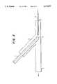
- FIG. 2is a schematic view of another embodiment of the device wherein the fuel containing additive is directed to the side of the device.
- the hollow bodyis designed to be rotationally symmetric about its lengthwise axis, i.e. it is cylindrical.
- the lower end of such a cylindrical bodycan be made flat or planar.
- This flat end of the cylinderhas at least one opening through which the fuel can enter and exit.
- This endcan, for example, be in the form of a lid with a screw closure interchangeably mounted at the lower end of the cylinder. If necessary, a choice may be made at this point between different lids with different numbers of openings and different opening sizes corresponding to the additive problem to be solved.
- the lower end of the hollow bodycan be in the shape of a segment of a sphere, i.e. hemispherical.
- This design toocan be formed, having regard to interchangeability and the number of openings, just like the flat design.
- the number and size of the openingsdepends among other things on the type of fuel and solid additive, temperature, and desired additive concentration and in the case of doubt may be determined by simple tests.
- the openingsare circular in shape (bores).
- the openingsmay be smaller than the particles of solid material added. It may also be preferable to provide these openings additionally with a close-mesh network, screen, or grid so that no larger solid particles can be swept out of the hollow body via the opening. It has proven advantageous for the solid material to be in the form of pellets.
- the pellets usedpreferably are spherically shaped and have a diameter of 1 to 10 mm, in particular 4 to 6 mm. Other shapes for the solid material such as tablets or tiny rods may be appropriate. They are usually what are known as molded bodies.
- ferroceneis an especially effective additive.
- the device according to the inventionis also especially suitable for the use of ferrocene as the solid additive. This is particularly true when the ferrocene, as described above, is in the form of spherical pellets that preferably have a diameter of about 5 mm. Depending on the diameter of the pellets, the diameter of the openings is likewise in the range of 1 to 10 mm. A range of 3 to 6 mm is preferred.
- the hollow bodycan be filled repeatedly with solid material.
- the end of the fuel line through which the fuel is fed to the lower end of the hollow bodyis at a distance from the body that depends on the outflow speed of the fuel or the pressure. However, it must be ensured that the fuel line is located far enough from the hollow body that its lower end is irrigated by the inflowing fuel. In case of doubt, this can be accomplished by simple testing. The distance is usually a few millimeters.
- the fuel irrigating the lower end of the hollow bodyusually drips or flows freely away from the lower end of the hollow body, is collected, and is conducted onward through a line in the direction of the engine or combustion chamber.
- the fuel lineis usually also a cylindrically shaped body.
- Angle ⁇is formed by the center axis of the hollow body filled with solid material and that of the fuel stream or fuel line (see FIG. 1). This angle is preferably about 150°.
- the two above-mentioned center axes that form the angle ⁇intersect exactly at the lower end of the filled hollow body. At this point it is also preferable to have an opening centered on the center axis of the filled hollow body.
- the device according to the inventionis preferably an integral component of a fuel supply system and is usually between the tank and the combustion chamber or engine.
- the systemis preferably closed so that no fuel and no fuel fumes can escape outside.
- Such a closurecan be in the form of a surrounding housing 6.
- the shape of the housingis of less importance.
- the housingis preferably designed so that it also serves to hold at least end portions of the hollow body and the fuel line 4, thus also permanently establishing the angle ⁇ .
- the device according to the invention and the method according to the inventionare particularly applicable to motor vehicles with internal combustion engines.
- stationery enginessuch as those used to drive compressors or electrical generators are also a preferred area of application.
- a passenger carsuch a device has the following approximate dimensions:
- the inventionalso relates to a method for direct addition of additives to liquid fuels using solid materials soluble in the fuel, characterized in that one end, provided with at least one opening, of a hollow body at least partially filled by fuel is irrigated with inflowing fuel.
- this methodit is preferable for the device according to the invention to be incorporated into one of the designs described.
- FIG. 1is a diagram in schematic form of one embodiment of the device according to the invention.
- a stream of fuel 2is conducted through a fuel line 4 to the lower end of hollow body 1.
- the center axis of the hollow body and the center axis the fuel line or fuel streamform an angle of approximately 140°.
- an opening 3is present at the lower end of the hollow body.
- the solid materialis contained in the hollow body.
- the fuelirrigates the lower end of the hollow body and passes in and out through the opening in the body.
- the outflowing fuel containing additiveis captured and conducted through a header 5 in the direction of a combustion chamber or engine. This header preferably leads downward but could also lead off to the side for example.
- a housing 6seals off the lower end of the hollow body and the discharge end of fuel line 4 hermetically from escape of fuel or fuel fumes to the environment and is connected to header 5.
- FIG. 2shows a similar arrangement to the embodiment of FIG. 1 but with a header 5 leading to the left side and with a hemispherical lower end of hollow body 1.
- This arrangementcan also advantageously be rotated or tilted slightly to the left so that the fuel with its additive is better able to run out through the header 5.
- the volumetric dimensions of a housing of a device as shown in FIG. 2are a horizontal cylindrical part having a length of 400 mm and an inside diameter of 50 mm and an upper cylindrical branch with a length of 270 mm and an inside diameter of 30 mm.
- FIG. 1An experimental setup was used, corresponding essentially to the device shown in FIG. 1.
- a commercial Diesel fuel from a fuel tankwas pumped through this device at the rate of 10 l/h.
- the deviceconsisted of a cylindrical hollow body (as a tubular insert 1) with an inside diameter of 22 mm and a central bore at the lower end, said body being filled with ferrocene pellets as well as of the incoming and outgoing fuel lines and of the surrounding housing.
- the inside diameter of the incoming fuel lineis 4.5 mm and the minimum distance between the lower end of the insert and the ingoing fuel line 4 is 1.5 mm.
- the dissolved quantity of ferroceneis determined by weighing from time to time.
- the insertwas given ends of various geometric shapes (hemispherical and flat).
- the size of the single opening or borewas also varied (3, 4, and 6 mm diameters).
- Each experimentwas run for 500 hours.
- the additive usedwas ferrocene spherical pellets 5 mm in diameter. When the opening was 4 and 6 mm in diameter, the experiments were broken off since the results were too scattered and reproducibility could not be achieved. The reason for this is that most of the pellets did not dissolve in the end of the insert but were flushed out of it. Of the various angles used, 150° resulted in a maximum rate of addition. The maximum linearity and reproducibility were achieved with a hemispherical end on the insert.
- the results of the experimentsare given in the tables below.
- the quality of the additive additionwas determined by the linearity of the graph of time versus quantity of additive dissolved with the aid of linear regression. The closer the regression coefficient noted was to 1, the better the linearity.
Landscapes
- Chemical & Material Sciences (AREA)
- Engineering & Computer Science (AREA)
- Oil, Petroleum & Natural Gas (AREA)
- Combustion & Propulsion (AREA)
- Organic Chemistry (AREA)
- Chemical Kinetics & Catalysis (AREA)
- General Chemical & Material Sciences (AREA)
- Mechanical Engineering (AREA)
- General Engineering & Computer Science (AREA)
- Cooling, Air Intake And Gas Exhaust, And Fuel Tank Arrangements In Propulsion Units (AREA)
- Production Of Liquid Hydrocarbon Mixture For Refining Petroleum (AREA)
- Liquid Carbonaceous Fuels (AREA)
Abstract
Description
______________________________________ Time (h) Quantity dissolved (g) Additive (ppm) ______________________________________ 0,00 0,00 0,0 8,00 0,26 3,9 24,00 1,00 5,1 47,25 1,65 4,3 90,00 3,36 4,6 95,00 3,69 4,7 112,00 4,95 5,4 123,50 5,52 5,5 143,00 6,35 5,4 168,00 7,19 5,2 190,00 8,47 5,4 210,50 10,25 5,9 237,75 11,40 5,8 280,25 13,54 5,9 297,00 14,48 5,9 318,50 15,74 6,0 340,25 17,32 6,2 361,00 17,97 6,1 384,00 19,03 6,0 401,25 20,41 6,2 421,00 21,74 6,3 442,00 22,30 6,2 463,75 23,37 6,1 482,00 24,70 6,3 500,00 26,06 6,4 ______________________________________ Regression coefficient: 0.999
______________________________________ Time (h) Quantity dissolved (g) Additive (ppm) ______________________________________ 0,00 0,00 0,00 6,00 1,62 32,9 25,50 7,20 34,4 48,00 11,65 29,6 72,25 16,11 27,2 93,00 21,92 28,7 109,75 26,88 29,9 120,00 29,01 29,5 143,00 34,49 29,4 169,15 41,19 29,7 193,00 49,77 31,5 211,00 54,12 31,3 240,50 60,80 30,8 256,50 64,83 30,8 282,50 75,23 32,5 300,00 78,97 32,1 322,25 84,26 31,9 339,00 88,09 31,7 356,00 92,29 31,6 380,75 96,25 30,8 402,00 99,65 30,2 418,25 103,49 30,2 440,00 108,69 30,1 463,50 117,15 30,8 481,50 121,69 30,8 500,00 126,44 30,8 ______________________________________ Regression coefficient: 1.000
______________________________________ Time (h) Quantity dissolved (g) Additive (ppm) ______________________________________ 0,00 0,00 0,0 6,00 0,38 7,8 24,00 1,87 9,5 46,25 5,52 14,5 90,00 9,12 12,4 93,25 9,48 12,4 108,00 10,57 11,9 124,75 12,68 12,4 137,50 13,83 12,3 172,00 20,10 14,2 195,50 21,47 13,4 212,00 22,89 13,2 234,00 25,52 13,3 285,75 35,33 15,1 301,00 37,49 15,2 318,00 39,54 15,2 345,00 43,60 15,4 364,00 45,55 15,3 382,00 47,06 15,0 399,50 48,40 14,8 421,50 49,28 14,3 440,00 51,99 14,4 460,25 54,24 14,4 479,50 57,32 14,6 500,00 60,44 14,7 ______________________________________ Regression coefficient: 0.998
______________________________________ Time (h) Quantity dissolved (g) Additive (ppm) ______________________________________ 0,00 0,00 0,0 5,00 2,40 58,5 23,75 7,20 37,0 47,00 8,80 22,8 71,50 11,20 19,1 96,50 12,80 16,2 102,50 15,20 18,1 109,50 16,80 18,7 126,00 20,80 20,1 152,50 25,60 20,5 174,50 32,80 22,9 198,50 37,60 23,1 224,00 44,00 24,0 272,00 56,80 25,5 293,50 60,80 25,3 320,00 63,20 24,1 369,50 71,20 23,5 393,75 86,40 26,8 417,50 90,40 26,4 440,50 92,80 25,7 466,00 96,80 25,3 485,50 99,20 24,9 500,00 103,20 25,2 ______________________________________ Regression coefficient: 0.992
______________________________________ Time (h) Quantity dissolved (g) Additive (ppm) ______________________________________ 0,00 0,00 0,0 17,50 6,60 46,0 23,50 9,90 51,4 45,75 18,90 50,4 69,75 26,70 46,7 93,75 34,20 44,5 119,00 38,10 39,0 124,00 40,80 40,1 143,00 48,30 41,2 149,00 50,10 41,0 191,00 63,00 40,2 214,50 71,10 40,4 219,50 73,50 40,8 226,00 74,70 40,3 241,50 81,60 41,2 246,00 82,50 40,9 266,00 90,00 41,3 289,25 98,10 41,4 313,25 106,50 41,5 317,25 107,10 41,2 333,75 112,80 41,2 359,25 120,30 40,8 386,50 129,00 40,7 403,50 138,90 42,0 430,00 146,10 41,4 438,00 147,30 41,0 450,75 153,90 41,6 475,50 161,70 41,5 500,00 169,20 41,3 ______________________________________ Regression coefficient: 0.999
______________________________________ Time (h) Quantity dissolved (g) Additive (ppm) ______________________________________ 0,00 0,00 0,0 5,25 0,80 18,6 24,00 4,80 24,4 46,00 12,00 31,8 70,00 17,60 30,7 93,00 22,40 29,4 101,00 24,80 29,9 108,00 27,20 30,7 124,00 31,20 30,7 132,17 33,60 31,0 149,00 37,60 30,8 155,50 40,00 31,4 199,00 50,40 30,9 206,00 52,00 30,8 211,00 54,40 31,4 229,75 58,40 31,0 253,00 61,60 29,7 276,50 65,60 28,9 301,50 68,80 27,8 307,50 71,20 28,2 314,50 73,60 28,5 331,00 77,60 28,6 355,00 82,40 28,3 379,50 89,60 28,8 403,50 94,40 28,5 429,00 100,80 28,7 477,00 113,60 29,0 500,00 118,40 28,9 ______________________________________ Regression coefficient: 0.997
Claims (10)
Applications Claiming Priority (2)
| Application Number | Priority Date | Filing Date | Title |
|---|---|---|---|
| DE4332933.0 | 1993-09-28 | ||
| DE4332933ADE4332933C2 (en) | 1993-09-28 | 1993-09-28 | Device for the additivation of liquid fuels |
Publications (1)
| Publication Number | Publication Date |
|---|---|
| US5573557Atrue US5573557A (en) | 1996-11-12 |
Family
ID=6498795
Family Applications (1)
| Application Number | Title | Priority Date | Filing Date |
|---|---|---|---|
| US08/313,812Expired - LifetimeUS5573557A (en) | 1993-09-28 | 1994-09-28 | Device for adding additives to liquid fuels in the fuel stream |
Country Status (2)
| Country | Link |
|---|---|
| US (1) | US5573557A (en) |
| DE (1) | DE4332933C2 (en) |
Cited By (20)
| Publication number | Priority date | Publication date | Assignee | Title |
|---|---|---|---|---|
| US6203586B1 (en)* | 2000-01-12 | 2001-03-20 | John W. Davis | Fire enhancement system |
| WO2003018727A1 (en)* | 2001-08-24 | 2003-03-06 | Dober Chemical Corporation | Fuel additive compositions |
| WO2003018726A1 (en)* | 2001-08-24 | 2003-03-06 | Dober Chemical Corporation | Controlled release additives in fuel systems |
| US20040014614A1 (en)* | 2002-07-16 | 2004-01-22 | Burrington James D. | Slow release lubricant additives gel |
| US20040020560A1 (en)* | 2002-08-01 | 2004-02-05 | Dehn James J. | Drip feed apparatus for a fuel container |
| US20040231615A1 (en)* | 2001-05-31 | 2004-11-25 | Vincent Matthew William | Process |
| US20040266631A1 (en)* | 2003-06-25 | 2004-12-30 | The Lubrizol Corporation | Gels that reduce soot and/or emissions from engines |
| US6860241B2 (en) | 1999-06-16 | 2005-03-01 | Dober Chemical Corp. | Fuel filter including slow release additive |
| US20050137097A1 (en)* | 2002-07-16 | 2005-06-23 | The Lubrizol Corporation | Controlled release of additive gel(s) for functional fluids |
| US7001531B2 (en) | 2001-08-24 | 2006-02-21 | Dober Chemical Corp. | Sustained release coolant additive composition |
| US20060086738A1 (en)* | 2002-08-01 | 2006-04-27 | Briggs & Stratton Corporation | Cap for a fuel container |
| US20080188386A1 (en)* | 2007-02-05 | 2008-08-07 | The Lubrizol Corporation | Low Ash Controlled Release Gels |
| US7581558B2 (en) | 2001-08-24 | 2009-09-01 | Cummins Filtration Ip Inc. | Controlled release of additives in fluid systems |
| US20090294379A1 (en)* | 2008-05-27 | 2009-12-03 | Dober Chemical Corporation | Controlled release of additive compositions |
| US7883638B2 (en) | 2008-05-27 | 2011-02-08 | Dober Chemical Corporation | Controlled release cooling additive compositions |
| US7938277B2 (en) | 2001-08-24 | 2011-05-10 | Dober Chemical Corporation | Controlled release of microbiocides |
| US8425772B2 (en) | 2006-12-12 | 2013-04-23 | Cummins Filtration Ip, Inc. | Filtration device with releasable additive |
| US8591747B2 (en) | 2008-05-27 | 2013-11-26 | Dober Chemical Corp. | Devices and methods for controlled release of additive compositions |
| US8702995B2 (en) | 2008-05-27 | 2014-04-22 | Dober Chemical Corp. | Controlled release of microbiocides |
| KR20170073494A (en) | 2015-12-18 | 2017-06-28 | 케이앤드엔 엔지니어링, 인크. | Hvac system air filter |
Families Citing this family (7)
| Publication number | Priority date | Publication date | Assignee | Title |
|---|---|---|---|---|
| RU2151959C1 (en)* | 1999-06-08 | 2000-06-27 | Томилов Виталий Георгиевич | Method for producing composite liquid fuel |
| DE10000395A1 (en)* | 2000-01-07 | 2001-07-12 | Volkswagen Ag | Purification of IC engine exhaust gases comprises passing through particle filter which removes carbon particulate, solid additive which assists regeneration of filter being added to fuel before it enters engine |
| RU2167365C1 (en)* | 2000-02-22 | 2001-05-20 | Военный инженерно-технический университет | Oil-containing media thermal utilization system |
| RU2229057C1 (en)* | 2003-08-18 | 2004-05-20 | Открытое акционерное общество "Северский трубный завод" | Method for combined oil-and-fuel-oil heating of steam smelting furnaces |
| RU2253798C1 (en)* | 2004-06-30 | 2005-06-10 | Черепанов Олег Валентинович | Method of heating steel melting furnace |
| RU2311588C1 (en)* | 2006-05-02 | 2007-11-27 | Открытое акционерное общество "Северский трубный завод" | Method of combined heating of industrial furnaces |
| RU2328656C1 (en)* | 2006-11-16 | 2008-07-10 | Государственное образовательное учреждение высшего профессионального образования Самарский государственный технический университет | Method of liquid fuel preparation for combustion |
Citations (4)
| Publication number | Priority date | Publication date | Assignee | Title |
|---|---|---|---|---|
| US2955028A (en)* | 1955-10-17 | 1960-10-04 | Ethyl Corp | Fuel systems for compression ignition engines |
| US4389220A (en)* | 1980-06-04 | 1983-06-21 | Syntex (U.S.A.) Inc. | Method of conditioning diesel engines |
| US5059217A (en)* | 1990-10-10 | 1991-10-22 | Arroyo Melvin L | Fluid treating device |
| US5299746A (en)* | 1991-09-04 | 1994-04-05 | Chemische Betriebe Pluto Gmbh | Apparatus and method for direct solid-fortification of fuels with ferrocene |
- 1993
- 1993-09-28DEDE4332933Apatent/DE4332933C2/ennot_activeExpired - Fee Related
- 1994
- 1994-09-28USUS08/313,812patent/US5573557A/ennot_activeExpired - Lifetime
Patent Citations (4)
| Publication number | Priority date | Publication date | Assignee | Title |
|---|---|---|---|---|
| US2955028A (en)* | 1955-10-17 | 1960-10-04 | Ethyl Corp | Fuel systems for compression ignition engines |
| US4389220A (en)* | 1980-06-04 | 1983-06-21 | Syntex (U.S.A.) Inc. | Method of conditioning diesel engines |
| US5059217A (en)* | 1990-10-10 | 1991-10-22 | Arroyo Melvin L | Fluid treating device |
| US5299746A (en)* | 1991-09-04 | 1994-04-05 | Chemische Betriebe Pluto Gmbh | Apparatus and method for direct solid-fortification of fuels with ferrocene |
Cited By (41)
| Publication number | Priority date | Publication date | Assignee | Title |
|---|---|---|---|---|
| US6860241B2 (en) | 1999-06-16 | 2005-03-01 | Dober Chemical Corp. | Fuel filter including slow release additive |
| US6203586B1 (en)* | 2000-01-12 | 2001-03-20 | John W. Davis | Fire enhancement system |
| AU2002249432B2 (en)* | 2001-05-31 | 2006-06-08 | Innospec Limited | Process for dosing an additive into a fuel |
| US7134405B2 (en)* | 2001-05-31 | 2006-11-14 | The Associated Octel Company Limited | Process |
| US20040231615A1 (en)* | 2001-05-31 | 2004-11-25 | Vincent Matthew William | Process |
| US8109287B2 (en) | 2001-08-24 | 2012-02-07 | Cummins Filtration Ip, Inc. | Controlled release of additives in fluid systems |
| US7938277B2 (en) | 2001-08-24 | 2011-05-10 | Dober Chemical Corporation | Controlled release of microbiocides |
| US6827750B2 (en) | 2001-08-24 | 2004-12-07 | Dober Chemical Corp | Controlled release additives in fuel systems |
| US6835218B1 (en) | 2001-08-24 | 2004-12-28 | Dober Chemical Corp. | Fuel additive compositions |
| US7591279B2 (en) | 2001-08-24 | 2009-09-22 | Cummins Filtration Ip Inc. | Controlled release of additives in fluid systems |
| US7581558B2 (en) | 2001-08-24 | 2009-09-01 | Cummins Filtration Ip Inc. | Controlled release of additives in fluid systems |
| US7001531B2 (en) | 2001-08-24 | 2006-02-21 | Dober Chemical Corp. | Sustained release coolant additive composition |
| WO2003018726A1 (en)* | 2001-08-24 | 2003-03-06 | Dober Chemical Corporation | Controlled release additives in fuel systems |
| WO2003018727A1 (en)* | 2001-08-24 | 2003-03-06 | Dober Chemical Corporation | Fuel additive compositions |
| US20100317553A1 (en)* | 2002-07-16 | 2010-12-16 | Burrington James D | Slow Release Lubricant Additives Gel |
| US7417012B2 (en) | 2002-07-16 | 2008-08-26 | The Lubrizol Corporation | Slow release lubricant additives gel |
| US7799745B2 (en) | 2002-07-16 | 2010-09-21 | The Lubrizol Corporation | Slow release lubricant additives gel |
| US8076273B2 (en) | 2002-07-16 | 2011-12-13 | The Lubrizol Corportion | Slow release lubricant additives gel |
| US20050137097A1 (en)* | 2002-07-16 | 2005-06-23 | The Lubrizol Corporation | Controlled release of additive gel(s) for functional fluids |
| US20050085399A1 (en)* | 2002-07-16 | 2005-04-21 | Burrington James D. | Slow release lubricant additives gel |
| US6843916B2 (en) | 2002-07-16 | 2005-01-18 | The Lubrizol Corporation | Slow release lubricant additives gel |
| US7384896B2 (en) | 2002-07-16 | 2008-06-10 | The Lubrizol Corporation | Controlled release of additive gel(s) for functional fluids |
| US8299000B2 (en) | 2002-07-16 | 2012-10-30 | The Lubrizol Corporation | Slow release lubricant additives gel |
| US20040014614A1 (en)* | 2002-07-16 | 2004-01-22 | Burrington James D. | Slow release lubricant additives gel |
| US20080257803A1 (en)* | 2002-07-16 | 2008-10-23 | The Lubrizol Corporation | Slow Release Lubricant Additives Gel |
| US20040020560A1 (en)* | 2002-08-01 | 2004-02-05 | Dehn James J. | Drip feed apparatus for a fuel container |
| US7159741B2 (en) | 2002-08-01 | 2007-01-09 | Briggs & Stratton Corporation | Cap for a fuel container |
| US6981532B2 (en) | 2002-08-01 | 2006-01-03 | Briggs & Stratton Corporation | Drip feed apparatus for a fuel container |
| US20060086738A1 (en)* | 2002-08-01 | 2006-04-27 | Briggs & Stratton Corporation | Cap for a fuel container |
| US6942124B2 (en) | 2002-08-01 | 2005-09-13 | Briggs & Stratton Corporation | Drip feed apparatus for a fuel container |
| US20040040619A1 (en)* | 2002-08-01 | 2004-03-04 | Dehn James J. | Drip feed apparatus for a fuel container |
| US20040266631A1 (en)* | 2003-06-25 | 2004-12-30 | The Lubrizol Corporation | Gels that reduce soot and/or emissions from engines |
| US7534747B2 (en) | 2003-06-25 | 2009-05-19 | The Lubrizol Corporation | Gels that reduce soot and/or emissions from engines |
| US8425772B2 (en) | 2006-12-12 | 2013-04-23 | Cummins Filtration Ip, Inc. | Filtration device with releasable additive |
| US8022021B2 (en) | 2007-02-05 | 2011-09-20 | The Lubrizol Corporation | Low ash controlled release gels |
| US20080188386A1 (en)* | 2007-02-05 | 2008-08-07 | The Lubrizol Corporation | Low Ash Controlled Release Gels |
| US7883638B2 (en) | 2008-05-27 | 2011-02-08 | Dober Chemical Corporation | Controlled release cooling additive compositions |
| US20090294379A1 (en)* | 2008-05-27 | 2009-12-03 | Dober Chemical Corporation | Controlled release of additive compositions |
| US8591747B2 (en) | 2008-05-27 | 2013-11-26 | Dober Chemical Corp. | Devices and methods for controlled release of additive compositions |
| US8702995B2 (en) | 2008-05-27 | 2014-04-22 | Dober Chemical Corp. | Controlled release of microbiocides |
| KR20170073494A (en) | 2015-12-18 | 2017-06-28 | 케이앤드엔 엔지니어링, 인크. | Hvac system air filter |
Also Published As
| Publication number | Publication date |
|---|---|
| DE4332933C2 (en) | 1995-10-12 |
| DE4332933A1 (en) | 1995-03-30 |
Similar Documents
| Publication | Publication Date | Title |
|---|---|---|
| US5573557A (en) | Device for adding additives to liquid fuels in the fuel stream | |
| DE2359414A1 (en) | DEVICE FOR ADJUSTING STEAM FOR A COMBUSTION ENGINE | |
| PT97951B (en) | A method and apparatus for improving the combustion efficiency of an internal combustion engine | |
| KR20020033828A (en) | Device for subsequently treating exhaust gases of an internal combustion engine | |
| US6450155B1 (en) | In-line fuel conditioner | |
| DE2048340C3 (en) | Device for cleaning gas leakage from internal combustion engines | |
| DE10259806A1 (en) | Device for adding an additive to the fuel of a motor vehicle | |
| DE10139418A1 (en) | Once Through Then Out internal combustion engine with direct injection has distance between injection device opening and ignition point of 0.1 to 0.24 times piston diameter | |
| US2053200A (en) | Fuel modifying device for internal combustion engines | |
| US4763632A (en) | Fuel collector | |
| CA1049788A (en) | Injection apparatus | |
| DE2056087B2 (en) | ||
| DE2659518A1 (en) | DEVICE FOR FUEL SAVING | |
| RU2327894C1 (en) | Internal combustion engine | |
| DE3322068A1 (en) | Control device for the alternative connection of the intake and pressure connections of a compressor to the connection of a storage chamber | |
| EP0598967A1 (en) | Cleaning gas turbine with abrasive blasting | |
| KR950004731B1 (en) | Exhaust purifier | |
| DE52146C (en) | Closure on the spout plug | |
| DE1782549C3 (en) | Device for removing flammable gas residues from liquid containers | |
| KR0124048Y1 (en) | Apparatus for eliminating tar in a vaporizer | |
| US2808246A (en) | Gas-liquid contact device | |
| DE102016014531B3 (en) | Fuel supply system | |
| JPS6455170A (en) | Pipe-type filter equipped with control device for air-intake amount | |
| JPS58500294A (en) | Cylinder head for internal combustion engines | |
| FR2423363A1 (en) | TANK FOR LIQUIDS |
Legal Events
| Date | Code | Title | Description |
|---|---|---|---|
| AS | Assignment | Owner name:CHEMISCHE BETRIEBE PLUTO GMBH, GERMANY Free format text:ASSIGNMENT OF ASSIGNORS INTEREST;ASSIGNORS:THUNKER, WALTER;LOHMANN, GABRIELE;MARSCHEWSKI, ARNIM;REEL/FRAME:007279/0846;SIGNING DATES FROM 19941124 TO 19941201 | |
| STCF | Information on status: patent grant | Free format text:PATENTED CASE | |
| FEPP | Fee payment procedure | Free format text:PAYOR NUMBER ASSIGNED (ORIGINAL EVENT CODE: ASPN); ENTITY STATUS OF PATENT OWNER: LARGE ENTITY | |
| AS | Assignment | Owner name:OCTEL DEUTSCHLAND GMBH, GERMANY Free format text:ASSIGNMENT OF ASSIGNORS INTEREST;ASSIGNOR:CHEMISCHE BETRIEBE PLUTO GMBH;REEL/FRAME:010756/0556 Effective date:20000111 | |
| FPAY | Fee payment | Year of fee payment:4 | |
| FPAY | Fee payment | Year of fee payment:8 | |
| AS | Assignment | Owner name:INNOSPEC DEUTSCHLAND GMBH, GERMANY Free format text:CHANGE OF NAME;ASSIGNOR:OCTEL DEUTSCHLAND GMBH;REEL/FRAME:018972/0423 Effective date:20060530 | |
| FPAY | Fee payment | Year of fee payment:12 |