US5573515A - Self purging angiographic injector - Google Patents
Self purging angiographic injectorDownload PDFInfo
- Publication number
- US5573515A US5573515AUS08/425,577US42557795AUS5573515AUS 5573515 AUS5573515 AUS 5573515AUS 42557795 AUS42557795 AUS 42557795AUS 5573515 AUS5573515 AUS 5573515A
- Authority
- US
- United States
- Prior art keywords
- syringe
- valve
- port
- patient
- flow
- Prior art date
- Legal status (The legal status is an assumption and is not a legal conclusion. Google has not performed a legal analysis and makes no representation as to the accuracy of the status listed.)
- Expired - Lifetime
Links
- 238000010926purgeMethods0.000titleclaimsabstractdescription28
- 238000002347injectionMethods0.000claimsabstractdescription94
- 239000007924injectionSubstances0.000claimsabstractdescription94
- 239000012530fluidSubstances0.000claimsabstractdescription52
- 230000033001locomotionEffects0.000claimsdescription19
- 239000000463materialSubstances0.000claimsdescription16
- 238000000034methodMethods0.000claimsdescription9
- 230000000903blocking effectEffects0.000claims3
- 230000005484gravityEffects0.000claims1
- 239000002872contrast mediaSubstances0.000abstractdescription61
- FAPWRFPIFSIZLT-UHFFFAOYSA-MSodium chlorideChemical compound[Na+].[Cl-]FAPWRFPIFSIZLT-UHFFFAOYSA-M0.000description47
- 239000011780sodium chlorideSubstances0.000description38
- 230000002572peristaltic effectEffects0.000description12
- 239000002699waste materialSubstances0.000description12
- 230000007246mechanismEffects0.000description11
- 210000001367arteryAnatomy0.000description10
- 239000003814drugSubstances0.000description9
- 229940079593drugDrugs0.000description9
- 210000004204blood vesselAnatomy0.000description8
- 230000002441reversible effectEffects0.000description8
- 210000003462veinAnatomy0.000description8
- 238000002583angiographyMethods0.000description6
- 230000002452interceptive effectEffects0.000description6
- 239000008280bloodSubstances0.000description5
- 210000004369bloodAnatomy0.000description5
- 230000004044responseEffects0.000description5
- 230000036772blood pressureEffects0.000description4
- 238000010586diagramMethods0.000description4
- 230000002792vascularEffects0.000description4
- 230000009471actionEffects0.000description3
- 230000017531blood circulationEffects0.000description3
- 230000008859changeEffects0.000description3
- 210000004351coronary vesselAnatomy0.000description3
- 230000000977initiatory effectEffects0.000description3
- 208000037260Atherosclerotic PlaqueDiseases0.000description2
- 208000034887Syringe issueDiseases0.000description2
- 230000002159abnormal effectEffects0.000description2
- 230000003213activating effectEffects0.000description2
- 210000000709aortaAnatomy0.000description2
- 230000000747cardiac effectEffects0.000description2
- 230000008602contractionEffects0.000description2
- 230000001186cumulative effectEffects0.000description2
- 230000003247decreasing effectEffects0.000description2
- 230000001419dependent effectEffects0.000description2
- 238000003384imaging methodMethods0.000description2
- 230000003287optical effectEffects0.000description2
- 208000032170Congenital AbnormalitiesDiseases0.000description1
- 208000031481Pathologic ConstrictionDiseases0.000description1
- 230000005856abnormalityEffects0.000description1
- 230000001133accelerationEffects0.000description1
- 230000004913activationEffects0.000description1
- 238000002399angioplastyMethods0.000description1
- 230000004872arterial blood pressureEffects0.000description1
- 210000002565arterioleAnatomy0.000description1
- QVGXLLKOCUKJST-UHFFFAOYSA-Natomic oxygenChemical compound[O]QVGXLLKOCUKJST-UHFFFAOYSA-N0.000description1
- 230000015572biosynthetic processEffects0.000description1
- 230000007698birth defectEffects0.000description1
- 210000005242cardiac chamberAnatomy0.000description1
- 210000000748cardiovascular systemAnatomy0.000description1
- 238000010276constructionMethods0.000description1
- 229940039231contrast mediaDrugs0.000description1
- 230000000881depressing effectEffects0.000description1
- 230000000994depressogenic effectEffects0.000description1
- 238000001514detection methodMethods0.000description1
- 230000002542deteriorative effectEffects0.000description1
- 230000009977dual effectEffects0.000description1
- 238000002594fluoroscopyMethods0.000description1
- 238000011010flushing procedureMethods0.000description1
- 238000003780insertionMethods0.000description1
- 230000037431insertionEffects0.000description1
- 210000005240left ventricleAnatomy0.000description1
- 238000004519manufacturing processMethods0.000description1
- 238000012544monitoring processMethods0.000description1
- 229910052760oxygenInorganic materials0.000description1
- 239000001301oxygenSubstances0.000description1
- 230000036961partial effectEffects0.000description1
- 230000035479physiological effects, processes and functionsEffects0.000description1
- 230000036316preloadEffects0.000description1
- 238000005086pumpingMethods0.000description1
- 230000002829reductive effectEffects0.000description1
- 230000033764rhythmic processEffects0.000description1
- 210000005245right atriumAnatomy0.000description1
- 230000003068static effectEffects0.000description1
- 230000036262stenosisEffects0.000description1
- 208000037804stenosisDiseases0.000description1
- 230000001360synchronised effectEffects0.000description1
- 231100000331toxicToxicity0.000description1
- 230000002588toxic effectEffects0.000description1
- 210000000264venuleAnatomy0.000description1
Images


Classifications
- A—HUMAN NECESSITIES
- A61—MEDICAL OR VETERINARY SCIENCE; HYGIENE
- A61M—DEVICES FOR INTRODUCING MEDIA INTO, OR ONTO, THE BODY; DEVICES FOR TRANSDUCING BODY MEDIA OR FOR TAKING MEDIA FROM THE BODY; DEVICES FOR PRODUCING OR ENDING SLEEP OR STUPOR
- A61M5/00—Devices for bringing media into the body in a subcutaneous, intra-vascular or intramuscular way; Accessories therefor, e.g. filling or cleaning devices, arm-rests
- A61M5/14—Infusion devices, e.g. infusing by gravity; Blood infusion; Accessories therefor
- A61M5/142—Pressure infusion, e.g. using pumps
- A61M5/14212—Pumping with an aspiration and an expulsion action
- A61M5/14216—Reciprocating piston type
- A—HUMAN NECESSITIES
- A61—MEDICAL OR VETERINARY SCIENCE; HYGIENE
- A61M—DEVICES FOR INTRODUCING MEDIA INTO, OR ONTO, THE BODY; DEVICES FOR TRANSDUCING BODY MEDIA OR FOR TAKING MEDIA FROM THE BODY; DEVICES FOR PRODUCING OR ENDING SLEEP OR STUPOR
- A61M31/00—Devices for introducing or retaining media, e.g. remedies, in cavities of the body
- A61M31/005—Devices for introducing or retaining media, e.g. remedies, in cavities of the body for contrast media
- A—HUMAN NECESSITIES
- A61—MEDICAL OR VETERINARY SCIENCE; HYGIENE
- A61M—DEVICES FOR INTRODUCING MEDIA INTO, OR ONTO, THE BODY; DEVICES FOR TRANSDUCING BODY MEDIA OR FOR TAKING MEDIA FROM THE BODY; DEVICES FOR PRODUCING OR ENDING SLEEP OR STUPOR
- A61M5/00—Devices for bringing media into the body in a subcutaneous, intra-vascular or intramuscular way; Accessories therefor, e.g. filling or cleaning devices, arm-rests
- A61M5/14—Infusion devices, e.g. infusing by gravity; Blood infusion; Accessories therefor
- A61M5/142—Pressure infusion, e.g. using pumps
- A61M5/145—Pressure infusion, e.g. using pumps using pressurised reservoirs, e.g. pressurised by means of pistons
- A61M5/1452—Pressure infusion, e.g. using pumps using pressurised reservoirs, e.g. pressurised by means of pistons pressurised by means of pistons
- A61M5/14546—Front-loading type injectors
- A—HUMAN NECESSITIES
- A61—MEDICAL OR VETERINARY SCIENCE; HYGIENE
- A61M—DEVICES FOR INTRODUCING MEDIA INTO, OR ONTO, THE BODY; DEVICES FOR TRANSDUCING BODY MEDIA OR FOR TAKING MEDIA FROM THE BODY; DEVICES FOR PRODUCING OR ENDING SLEEP OR STUPOR
- A61M5/00—Devices for bringing media into the body in a subcutaneous, intra-vascular or intramuscular way; Accessories therefor, e.g. filling or cleaning devices, arm-rests
- A61M5/14—Infusion devices, e.g. infusing by gravity; Blood infusion; Accessories therefor
- A61M5/168—Means for controlling media flow to the body or for metering media to the body, e.g. drip meters, counters ; Monitoring media flow to the body
- A61M5/172—Means for controlling media flow to the body or for metering media to the body, e.g. drip meters, counters ; Monitoring media flow to the body electrical or electronic
- A—HUMAN NECESSITIES
- A61—MEDICAL OR VETERINARY SCIENCE; HYGIENE
- A61M—DEVICES FOR INTRODUCING MEDIA INTO, OR ONTO, THE BODY; DEVICES FOR TRANSDUCING BODY MEDIA OR FOR TAKING MEDIA FROM THE BODY; DEVICES FOR PRODUCING OR ENDING SLEEP OR STUPOR
- A61M5/00—Devices for bringing media into the body in a subcutaneous, intra-vascular or intramuscular way; Accessories therefor, e.g. filling or cleaning devices, arm-rests
- A61M5/14—Infusion devices, e.g. infusing by gravity; Blood infusion; Accessories therefor
- A61M2005/1401—Functional features
- A61M2005/1403—Flushing or purging
- Y—GENERAL TAGGING OF NEW TECHNOLOGICAL DEVELOPMENTS; GENERAL TAGGING OF CROSS-SECTIONAL TECHNOLOGIES SPANNING OVER SEVERAL SECTIONS OF THE IPC; TECHNICAL SUBJECTS COVERED BY FORMER USPC CROSS-REFERENCE ART COLLECTIONS [XRACs] AND DIGESTS
- Y10—TECHNICAL SUBJECTS COVERED BY FORMER USPC
- Y10S—TECHNICAL SUBJECTS COVERED BY FORMER USPC CROSS-REFERENCE ART COLLECTIONS [XRACs] AND DIGESTS
- Y10S128/00—Surgery
- Y10S128/12—Pressure infusion
Definitions
- This inventionrelates to angiography and more specifically, the injector used to inject a medical fluid such as radiographic contrast material into living organisms.
- the major components of the circulatory systemare the heart, blood vessels, and the blood, all of which are vital to the transportation of materials between the external environment and the different cells and tissues of the human body.
- the blood vesselsare the network of passageways through which the blood travels in the human body.
- arteriescarry the oxygenated blood away from the left ventricle of the heart. These arteries are aligned in progressively decreasing diameter and pressure capability from the aorta, which carries the blood immediately out of the heart to other major arteries, to smaller arteries, to arterioles, and finally to tiny capillaries, which feed the cells and tissues of the human body.
- veinscarry the oxygen depleted blood back to the right atrium of the heart using a progressively increasing diameter network of venules and veins.
- a physicianmay need to examine the heart and connected network of vessels. The physician may also need to correct any problems encountered during the examination with a catheter or similar medical instrument.
- Angiographyis a procedure used in the detection and treatment of abnormalities or restrictions in blood vessels.
- a radiographic image of a vascular structureis obtained by injecting radiographic contrast material through a catheter into a vein or artery.
- the vascular structures fluidly connected with the vein or artery in which the injection occurredare filled with contrast material.
- X-raysare passed through the region of the body in which the contrast material was injected.
- the X-raysare absorbed by the contrast material, causing a radiographic outline or image of the blood vessel containing the contrast material.
- the x-ray images of the blood vessels filled with contrast materialare usually recorded onto film or videotape and are displayed on a fluoroscope monitor.
- Angiographygives the doctor an image of the vascular structures in question. This image may be used solely for diagnostic purposes, or the image may be used during a procedure such as angioplasty where a balloon is inserted into the vascular system and inflated to open a stenosis caused by atherosclerotic plaque buildup.
- the angiographic catheteris connected to either a manual or an automatic contrast injection mechanism.
- a simple manual contrast injection mechanismtypically has a syringe and a catheter connection.
- the syringeincludes a chamber with a plunger therein. Radiographic contrast material is suctioned into the chamber. Any air is removed by actuating the plunger while the catheter connection is facing upward so that any air, which floats on the radiographic contrast material, is ejected from the chamber into the air.
- the catheter connectionis then attached to a catheter that is positioned in a vein or artery in the patient.
- the plungeris manually actuated to eject the radiographic contrast material from the chamber, through the catheter, and into a vein or artery.
- the user of the manual contrast injection mechanismmay adjust the rate and volume of injection by altering the manual actuation force applied to the plunger.
- valve mechanismwhich controls which of the fluids will flow into the valving mechanism and out to the catheter within the patient.
- the valve mechanismcontains a plurality of manual valves that the user operates manually to open and close that particular fluid channel. When the user suctions or injects contrast fluid into the chamber, the fluid is pulled from the valve mechanism via the open valves. By changing the valve positions, another fluid may be injected.
- Currently used motorized injection devicesconsist of a syringe connected to a linear actuator.
- the linear actuatoris connected to a motor, which is controlled electronically.
- the operatorenters into the electronic control a fixed volume of contrast material to be injected at a fixed rate of injection.
- the fixed rate of injectionconsists of a specified initial rate of flow increase and a final rate of injection until the entire volume of contrast material is injected.
- the optimal flow rate of injectionsvaries considerably between patients.
- the rate and volume of contrast injectionis dependent on the size of and blood flow rate within the chamber or blood vessel being injected. In many or most cases, these parameters are not known precisely.
- the optimal rate of injectioncan change rapidly, as the patient's condition changes in response to drugs, illness, or normal physiology. Consequently, the initial injection of contrast material may be insufficient in flow rate to outline the structure on x-ray imaging, necessitating another injection. Conversely, an excessive flow rate might injure the chamber or blood vessel being injected, cause the catheter to be displaced (from the jet of contrast material exiting the catheter tip), or lead to toxic effects from contrast overdose (such as abnormal heart rhythm).
- the operatorcan choose between two systems for injecting contrast material: a manual injection system which allows for a variable, operator interactive flow rate of limited flow rate and a preprogrammed motorized system without operator interactive feedback (other than the operator can start/stop the procedure).
- the present inventionis an apparatus and method for delivering medical fluid (such as radiographic material) from a fluid reservoir to a patient which features a self purging operation to eliminate air.
- the apparatus of the present inventionincludes an inlet port for connection to a fluid reservoir, a syringe and a valve connected in a flow path between the supply port and the syringe.
- the medical fluidis drawn from the fluid reservoir through the first valve and into the syringe by rearward movement of the syringe plunger or piston.
- the pistonis moved forward to expel air through the first valve to the inlet port.
- the first valvepermits air flow through the flow path from the syringe to the inlet port, but blocks flow of medical fluid back to the inlet port.
- the apparatusalso include, and preferred embodiments, a second valve which is connected between the syringe and the patient.
- the second valveis in a closed state during the fill and air purge operation.
- the second valveopens to permit flow of the medical fluid under pressure from the syringe to the patient.
- the first valveprevents flow of a medical fluid from the syringe to the inlet port.
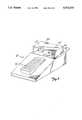
- FIG. 1is a perspective view illustrating a preferred embodiment of the angiographic injector system of the present invention.
- FIGS. 2A-2Gare diagrams illustrating operations of the system of FIG. 1.
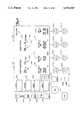
- FIG. 3is an electrical block diagram of the control system of the injector system of FIG. 1.
- FIG. 4illustrates front panel controls and displays of a preferred embodiment of the injector system of the present invention.
- FIGS. 5A and 5Bare side and partial top perspective views of the remote control of the system of FIG. 1.
- FIG. 6is a perspective view of a foot operated remote control.
- FIGS. 7A-7Dillustrate the operation of the inlet check valve and manifold during contrast fill, air purge, and patient inject operations.
- FIGS. 8A-8Cillustrate operation of the inlet check valve in greater detail.
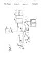
- FIG. 1shows angiographic injector system 10 for injecting radiographic contrast material into a blood vessel under interactive physician control.
- System 10includes main console 12, hand held remote control 14, syringe holder 16, syringe body 18, syringe plunger 20, radiographic material reservoir (bottle) 22, one-way valve 24, manifold 26, high pressure tube 28, catheter 30, patient medication port 32, three-way stop-cock 34, T-connector 36, pressure transducer 38, stop-cock 40, tubing 42, peristaltic pump 44, saline check valve 46, waste check valve 48, saline bag 50, waste bag 52, and bag support rack 54.
- Console 12houses the electrical controls for system 10, together with the motors which drive piston 20 and peristaltic pump 44.
- user interface 54provides control switches 56 and display 58 through which the user may enter control settings and monitor the operational state of system 10.
- Remote control 14is connected to console 12 by cable 60 (although in other embodiments remote control 14 may be connected by a wireless connection such as an RF, infrared optic, or ultrasonic link).
- Remote control 14is, in the embodiment shown in FIG. 1, a hand-held control which includes reset and saline push button switches 62 and 64, respectively, and flow rate control lever or trigger 66. By squeezing trigger 66, the user can provide a command signal to console 12 to provide a continuously variable injection rate.
- Syringe holder 16projects from the left hand side of console 12.
- Syringe holder 16is preferably a clear material, and includes a half cylindrical back shell 68, a half cylindrical front door 70 (which is shown in open position in FIG. 1), and reservoir holder 72.
- Syringe 18is a transparent or translucent plastic cylinder having its open end 74 connected to console 12. Closed end 76 of syringe 18 contains two ports: upper port 78 and lower port 80.
- Plunger 20is movable within syringe body 18. Plunger 20 is connected to, and driven by a motor located within console 12.
- Radiographic contrast material reservoir 22is connected through one-way check valve 24 to upper port 78. Radiographic contrast material is drawn from reservoir 22 through check valve 24 and upper port 78 into the pumping chamber defined by syringe body 18 and plunger 20.
- Check valve 24is preferably a weighted one-way valve which permits air to flow from syringe body 18 back into reservoir 22, but will not permit radiographic contrast material to flow from syringe body 18 to reservoir 22. This permits automatic purging of air from the system, as will be described in more detail later.
- Lower port 80 of syringe body 18is connected to manifold 26.
- Manifold 26includes a spring biased spool valve which normally connects transducer/saline port 82 and patient port 84. When radiographic contrast material is to be injected, the pressure of the radiographic material causes the spool valve to change states so that lower port 80 is connected to patient port 84.
- High pressure tube 28is a flexible tube which connects patient port 84 to catheter 30.
- Three-way stop-cock 34is located at the distal end of tube 28.
- Rotatable luer lock connector 86is connected to stop-cock 34 and mates with luer connector 88 at the proximal end of catheter 30.
- Stop-cock 34either blocks flow between tube 28 and catheter 30, permits flow, or connects medication port 32 to catheter 30.
- system 10In addition to injecting radiographic material into a patient through catheter 30, system 10 also permits other related functions to be performed.
- a device for delivering the patient medication(not shown in FIG. 1) may be connected to medication port 32 when medication is to be delivered through catheter 30 to the patient.
- pressure transducer 38monitors the blood pressure through the column of fluid which extends from catheter 30, tube 28, patient port 84, manifold 26, transducer/saline port 82, tubing 90, T-connector 36, and tubing 92.
- Transducer 38has an associated stop-cock 40 which allows transducer 38 to be exposed to atmospheric pressure during calibration and also allows for removal/expulsion of trapped air so the dome chamber of transducer 38 can be flushed with saline.
- Peristaltic pump 44supplies saline solution from bag 50 through saline check valve 46, tubing 42, T-connector 36 and tubing 90 to saline port 82.
- peristaltic pump 44When peristaltic pump 44 is operating to supply saline solution, the saline solution is supplied through manifold 26 to patient port 84 and then through tube 28 to catheter 30.
- Peristaltic pump 44also operates in an opposite direction to draw fluid from catheter 30 and through tube 28, manifold 26, tubing 90, T-connector 36 and tubing 42 to waste check valve 48 and then into waste collection bag 52.
- syringe body 18, manifold 26, tube 28, catheter 30, T-connector 36, tubing 42, check valves 46 and 48, bags 50 and 52, and tubing 90 and 92are all disposable items. They must be installed in system 10 each time an angiography procedure is to be performed with a new patient. Once system 10 is set up with all the disposable items installed, door 70 is closed, and syringe body 18 filled with contrast material and purged of air, the user (typically a physician) enters into system 10 the safety parameters that will apply to the injection of radiographic contrast material.
- safety parameterstypically include the maximum amount of radiographic contrast material to be injected during any one injection, the maximum flow rate of the injection, the maximum pressure developed within syringe body 18, and the maximum rise time or acceleration of the injection.
- the useroperates remote control 14 by squeezing trigger 66.
- system 10causes the flow rate of the injection to increase as the force or distance of travel of trigger 66 is increased.
- System 10allows the user to tailor the contrast injections to the needs of the patient, thereby maximizing the quality of the procedure, increasing the safety, and reducing the amount of contrast material required to perform the fluoroscopic examination.
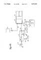
- FIGS. 2A-2Gare diagrams illustrating fluid flow paths during seven different operations of system 10. Those operations are contrast fill (FIG. 2A), air purge (FIG. 2B), patient inject (FIG. 2C), patient pressure (FIG. 2D), saline flush (FIG. 2E), aspirate waste (FIG. 2F), and medicate patient (FIG. 2G).
- FIGS. 2A-2Gare diagrams illustrating fluid flow paths during seven different operations of system 10. Those operations are contrast fill (FIG. 2A), air purge (FIG. 2B), patient inject (FIG. 2C), patient pressure (FIG. 2D), saline flush (FIG. 2E), aspirate waste (FIG. 2F), and medicate patient (FIG. 2G).
- the contrast fill operation illustrated in FIG. 2Ainvolves the filling of syringe body 18 with radiographic contrast material from reservoir (contrast media supply) 22.
- the contrast fill operationis performed during initial set up of system 10, and may be repeated during operation of system 10 whenever syringe body 18 is running low on radiographic contrast material.
- plunger 20is initially driven to its furthest forward position adjacent closed end 76 of syringe body 18. This will expel to the atmosphere the majority of the air which is located within syringe body 18.
- Plunger 20is then retracted, which creates a vacuum within syringe body 18 which draws contrast material from reservoir 22 through check valve 24 into syringe body 18 through upper port 78.
- the Contrast Fill operationtypically will result in some air being drawn into or remaining within syringe body 18. It is important, of course, to prevent air from being injected into the patient through catheter 30. That is the purpose of the Air Purge operation shown in FIG. 2B. Also, the location of two ports at different elevations allows for a greater amount of safety in preventing air bubbles in the injection.
- plunger 20travels forward to expel trapped air within syringe body 18.
- the airbeing lighter than the contrast material, gathers near the top of syringe body 18.
- one-way valve 24is a weighted one-way valve which allows flow of radiographic contrast material from reservoir 22 to upper port 78, but will not allow radiographic contrast material to flow in the opposite direction from upper port 78 to reservoir 22.
- Valve 24will, however, allow air to flow from port 78 to reservoir 22.
- valve 24closes to prevent any further flow toward reservoir 22.
- Valve 24can also, in alternative embodiments, can be a solenoid actuated or motor driven valve operated under control of the electric circuitry within console 12. In either case, valve 24 is capable to withstanding the relatively high pressures to which it will be subjected during the inject operation. Preferably, valve 24 is capable of withstanding static fluid pressures up to about 1200 p.s.i.
- FIG. 2Cillustrates the Patient Inject operation.
- Plunger 20travels forward under the interactive control of the user, who is controlling trigger 66 of remote control 14.
- the movement of plunger 20creates hydraulic pressure to force contrast material out of syringe body 18 through lower port 80 and through manifold 26 and high pressure tube 28 into catheter 30.
- syringe lower port 80 and patient port 84are connected for fluid flow during the patient inject operation.
- Manifold 26contains a valve which controls the routing of fluid connections between patient port 84 and either syringe bottom port 80 or transducer/saline port 82.
- manifold 26includes a spool valve which is spring biased so that patient port 84 is normally connected to transducer/saline port 82 (as illustrated in FIGS. 2A and 2B).
- the bias force against the spool valveis overcome so that syringe bottom port 80 is connected to patient port 84, and transducer/saline port 82 is disconnected the valve within manifold 26 protects pressure transducer 38 from being exposed to the high pressure generated by the patient inject operation.
- the spool valveopens automatically during the patient inject operation in response to increase pressure exerted on it from the syringe lower port 80.
- the spool valvecloses and returns to its original position allowing for connection of patient port 84 to transducer 38 when a slight vacuum is applied by retraction of plunger 20 at the end of each Patient Inject operation.
- the valve within manifold 26is an electromechanical or motor driven valve which is actuated at appropriate times to connect either syringe lower port 80 or transducer/saline port 82 to patient port 84.
- the actuator mechanismis controlled by console 12.
- the valveprotects pressure transducer 38 from being exposed to high pressure.
- FIG. 2Dillustrates the Patient Pressure operation.
- System 10allows for reading of the patient's blood pressure, which is monitored through catheter 30.
- Patient blood pressurecan be monitored through the use of pressure transducer 38 at any time except during the patient inject, saline flush, and waste aspirate operations.
- the pressure reading being produced by pressure transducer 38may be normalized by manually opening stop-cock 40 and closing stop-cock 34 to expose pressure transducer 38 to atmospheric pressure.
- saline solutionis used to flush all of the internal lines, pressure transducer chamber 38, tube 28, and catheter 30.
- peristaltic pump 44is operating in a direction which causes saline solution to be drawn from bag 50 through check valve 46 and through tubing 42 to saline port 82.
- Manifold 26connects saline port 82 to patient port 84 so that saline solution is pumped out of patient port 84 and through tube 28 and catheter 30.
- patient port 84is again connected to saline port 82.
- peristaltic pump 44is operating in the opposite direction from its rotation during the saline flush operation.
- patient fluidsare aspirated from patient port 84 to saline port 82 and then through tubing 42 and check valve 48 into waste collection bag 52.
- Peristaltic pump 44acts as a valve pinching/occluding tubing 42 and preventing back flow to/from saline and waste containers 50 and 52 in conjunction with check valves 46 and 48.
- System 10allows for that option by providing patient medication port 32. As shown in FIG. 2G, when stop-cock 34 is open, a medication source connected to port 32 will be connected to patient port 84, and thereby to catheter 30. During the medicate patient operation, peristaltic pump 44 and plunger 20 are not moving.
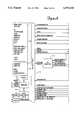
- FIG. 3is an electrical block diagram of the control system which controls the operation of angiographic injector system 10.
- the electrical control systemincludes digital computer 100, which receives input signals from remote control 14 and front panel controls 56 through interface 102, and provides signals to display 58 to display operation data, alerts, status information and operator prompts.
- Computer 100controls the motion of plunger 20 through a motor drive circuit which includes motor 104, motor amplifier 106, tachometer 108, potentiometer 110, a rectifier 112, pressure sensing load cell 114, and A/D converter 160.
- motor drive circuitwhich includes motor 104, motor amplifier 106, tachometer 108, potentiometer 110, a rectifier 112, pressure sensing load cell 114, and A/D converter 160.
- Motor amplifier 106provides a Drive 1 signal to motor 104 in response to Control Voltage, Fwd/Rev, and /Brake signals from computer 100 and a speed feedback signal from tachometer 108 through rectifier 112.
- the outputs of tachometer 108 and potentiometer 110are supplied to computer 100 through A/D converter 116 as Speed Monitor and Position Monitor signals. These allow computer 100 to check motor speed, motor direction, and position (volume is a calculated value).
- Pressure sensor 114senses motor current or plunger force in order to measure the pressure being applied to the radiographic contrast material within syringe body 18. This Pressure Monitor Signal is supplied through A/D converter 116 and interface 102 to computer 100.
- Peristaltic pump 44is driven under the control of computer 100 through pump motor 120, motor driver 122 and optical encoder 124.
- Computer 100provides Saline (Forward) and Waste (Reverse) drive signals to motor driver 122 to operate pump motor 120 in a forward direction for saline flush and a reverse direction for waste aspiration.
- Optical encoder 124provides the Speed Direction Monitor signal to interface 102 which indicates both the speed and the direction of rotation of pump motor 120.
- FIG. 3illustrates an embodiment of the control system in which valve motor 130 is used to actuate valves such as one-way valve 24 and the valve within manifold 26.
- computer 100controls valve motor 130 through motor driver 132, and monitors position through a Position Monitor feedback signal from potentiometer 134.
- valve motor 130is a stepper motor.
- Computer 100monitors temperature of the contrast material based upon a Temp Monitor signal from temperature sensor 140. Temperature sensor 140 is preferably positioned near syringe body 18. If the temperature being sensed by temperature sensor 140 is too high, computer 100 will disable operation motor 104 to discontinue patient injection. If the temperature is to low, computer 100 provides a /Temp Enable drive signal to heater drive 150, which energizes heater 152. In one preferred embodiment, heater 152 is a resistive film heater which is positioned within syringe holder 116 adjacent to syringe body 18.
- Computer 100also receives feedback signals from contrast bottle sensor 160, forward limit sensor 162, reverse limit sensor 164, syringe missing sensor 166, chamber open sensor 168, no contrast bubble detector 170, and air in line bubble detector 172.
- Contrast bottle sensor 160is a miniature switch located within reservoir holder 72. The state of the Contrast Bottle Present signal from sensor 160 indicates whether a reservoir 22 is in position within holder 72. If reservoir 22 is not present, computer 100 will disable the fill operation.
- Forward limit and reverse limit sensors 162sense the end limit positions of plunger 20. When plunger 20 reaches its forward limit position, no further forward movement of plunger 20 is permitted. Similarly, when reverse limit sensor 164 indicates that plunger 20 has reached its reverse limit position, no further reverse movements are permitted.
- Syringe missing sensor 166is a miniature switch or infrared emitter/detector which indicates when syringe body 18 is not in position within syringe holder 16. If syringe body 18 is not in position, all movement functions are disabled except that plunger 20 can move to its reverse limit position (i.e., return to zero).
- Chamber open sensor 168is a miniature switch or infrared emitter/detector which senses when door 70 of syringe holder 16 is open. When the signal from sensor 168 indicates that door 70 is open, all movement functions are disabled. Only when door 70 is closed and locked may any movement be allowed. When door 70 is indicated as closed and sensor 166 indicates the syringe body 18 is in position, other normal functions of the system 10 can proceed.
- Bubble detector 170is positioned between reservoir 22 and top port 78, and is preferably an infrared emitter/detector which senses air bubbles. If an air bubble is sensed in the flow path between reservoir 22 and top port 78 during a fill operation, the fill operation is disabled until a new reservoir is connected.
- Bubble detector 172is positioned to sense air bubbles in high pressure line 28. It is preferably an infrared emitter/detector type of bubble detector. Any air bubble which is sensed in high pressure line 28 results in the disabling of all fluid push out functions, whether the fluid is saline solution from peristaltic pump 44 or contrast material from syringe body 18.
- the control system of FIG. 3also includes the capability to provide a control signal to x-ray equipment through relay 180 which is controlled by computer 100.
- computer 100receives data from blood pressure transducer 38 and from an electrocardiograph (ECG) system, which is separate from injector system 10.
- ECGelectrocardiograph
- the Pressure and ECG signalsare received through signal conditioners and A/D converter 190, and are transferred to computer 100.
- the ECG signalis used by computer 100 in one preferred embodiment, to synchronize operation of motor 104 (and thus the Patient Inject operation) with heart beats.
- the injection of radiographic contrast materialis synchronized to the coronary artery blood flow.
- the time periods of systole and diastoleare determined using an electrocardiographic (ECG) electrical signal, arterial blood pressure waveform analysis, or other timing based on the heart rate.
- ECGelectrocardiographic
- the injection of contrast materialis interrupted during the period of systole, which reduces or stops contrast injection during this time.
- remote control 14the operator can vary the rate of contrast injection into the coronary artery while computer 100 automatically pulses the contrast injection to the cardiac cycle
- the inertial forces of the moving contrast material and expansion of the containers and tubing holding the contrast material and transmitting it to the patientcan cause a phase lag between movement of plunger 20 within syringe body 18 and movement of contrast material out of catheter 30 into the patient.
- a variable time offsetcan be entered through control panel 54 such that the timing of the cardiac cycle can be offset by a selected time. Since the magnitude of the phase lag may be dependent on the frequency of the heart rate, an algorithm within computer 100 continuously and automatically adjusts the magnitude of the time offset, based on the instantaneous heart rate during the injection of contrast material.
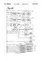
- FIG. 4shows one embodiment of control panel 54 which illustrates the front panel control switches 56 and display 58 of one embodiment of the present invention.
- Front panel control switches 56include Set Up/Fill/End switch 200, Purge switch 202, Aspirate switch 204, Saline switch 206, Enable OK switch 208, Injection Volume Limit switches 210a and 210b, Injection Flow Rate Limit switches 212a and 212b, Injection Pressure Limit switches 214a and 214b, Rise Time switches 216a and 216b, OK switch 218, Injection Range Toggle switch 220, Large Injection OK switch 222, and Stop switch 224.
- Set Up/Fill/End switch 200is a momentary push button switch. When it is first activated, the user will be notified to place syringe 18 in syringe holder 16. When syringe 18 has been placed in syringe holder 16 (which is indicated to computer 100 by sensor 166), the user will be instructed to close and lock the chamber (i.e., to close door 70). Plunger 20 is moved to its full forward position expelling all air within the syringe. Display 58 then indicates to the operator that contrast reservoir 22 should be connected.
- contrast reservoir 22Once contrast reservoir 22 has been put in place, the operator is requested to depress OK switch 218, at which time plunger 20 will retract at a set rate (preferably corresponding to a flow rate of 10 ml per second) to the maximum syringe volume. If the real speed (as indicated by feedback to computer 100 from A/D converter 116) is greater than the set speed, system 10 will stop.
- plunger 20is at its rearward most position, motor 104 is actuated to move plunger 20 forward to purge all air bubbles.
- Pressure sensor 114provides an indication of when one-way valve 24 is closed and pressure is beginning to build up within syringe body 18. Once the purge is completed, the total volume injected and the number of injections counter is reset.
- switch 200also allows for full retraction and disengagement of plunger 20 from syringe body 18.
- Purge switch 202is a protected momentary push button switch. When activated, Purge switch 202 causes plunger 20 to move forward to expel air through top port 78. The forward movement of plunger 20 is limited and stopped when a predetermined pressure within syringe 18 is reached. This is sensed by pressure sensor 114. The purge operation which is initiated by Purge switch 202 will expel air within syringe 20. The user may also use Purge switch 202 to purge fluid through patient port 84 by depressing and holding Purge switch 202 continuously on.
- Aspirate switch 204is a momentary push button switch which causes computer 100 to activate pump motor 120 of peristaltic pump 44. Pump motor 120 is operated to aspirate catheter 30 at a set speed, with the aspirated fluid being collected in waste bag 52. All other motion functions are disengaged during aspiration. If the real speed of motor 120 is greater than a set speed, computer 100 will stop motor 120.
- Saline switch 206is an alternate action switch. Pump motor 120 is activated in response to Saline switch 206 being pushed on, and saline solution from bag 50 is introduced into manifold 26 and catheter 30 at a set speed. If Saline switch 206 is not pushed a second time to stop the flow of saline solution within 10 seconds, computer 100 automatically stops pump motor 120. If a time-out is reached, Saline switch 206 must be reset to its original state prior to initiating any further actions.
- Enable OK switch 208is a momentary push button switch. After the system has detected a disabling function at the end of an injection other than a limit, Enable OK switch 208 must be activated prior to activating OK switch 218 and initiating any further function.
- Injection Volume Limit keys 210a and 210bare pushed to either increase or decrease the maximum injection volume that the system will inject during any one injection. Key 210a causes an increase in the maximum volume value, and key 210b causes a decrease. Once the maximum injection volume limit has been set, if the measured volume reaches the set value, computer 100 will stop motor 104 and will not restart until OK switch 218 has been depressed. If a large injection (i.e., greater than 10 ml) has been selected, OK switch 218 and Large Injection OK switch 220 must both be reset prior to initiating the large injection.
- Rate Limit keys 212a and 212ballow the physician to select the maximum flow rate that the system can reach during any one injection. If the measured rate (which is determined by the feedback signals from tachometer 108 and potentiometer 110) reaches the set value, computer 100 will control motor 104 to limit the flow rate to the set value.
- Injection Pressure Limit keys 214a and 214ballow the physician to select the maximum pressure that the system can reach during any one injection. If the measured pressure, as determined by pressure sensor 114, reaches the set value, computer 100 will control motor 104 to limit the pressure to the injection pressure limit. The injection rate will also be limited as a result.
- Rise Time keys 216a and 216ballow the physician to select the rise time that the system will allow while changing flow rate during any one injection.
- Computer 100controls motor 104 to limit the rise time to the set value.
- keys 210a-210b, 212a-212b, 214a-214b, and 216a-216bcan be replaced by other devices for selecting numerical values. These include selector dials, numerical keypads, and touch screens.
- OK switch 218is a momentary push button switch which resets functions and hardware sensors. In response to OK switch 218 being activated, computer 100 controls display 58 to ask the operator to acknowledge that the correct function has been selected. Activation of OK switch 218 causes the status to be set to Ready.
- Injection Range switch 220is a toggle switch. Depending on whether switch 220 is in the "small” or “large” position, it selects either a high or a low injection volume range for the next injection.
- Display panel 58includes Set-Up display 250, Status display 252, Alerts display 254, Limits display 256, total number of injections display 260, total volume injection display 262, flow rate display 264, injection volume display 266, injection volume limit display 268, injection rate limit display 270, pressure limit display 272, rise time minimum display 274, large injection display 276, and real time clock display 278.
- Alerts display 254 and Limits display 256notify the operator of conditions in which system 10 has encountered a critical control parameter and will disable operation, or has reached an upper or lower limit and will continue to function in a limited fashion, or has reached an upper or lower limit and will continue to operate.
- Total number of injections display 260displays the total number of injections (cumulative) given for the current patient case. The cumulative total volume injected during the current patient case is displayed by total volume display 262.
- Displays 264 and 266provide information on the current or last injection.
- Display 264shows digital value of the real time flow rate to the patient during injection. Once the injection is completed, the value displayed on display 264 represents the peak flow rate reached during that injection.
- Display 266shows the digital value of the volume injected during the most recent injection.
- Display 268displays the digital value of the maximum injection volume selected by operation of switches 210a and 210b.
- display 270shows the digital value of the maximum flow rate that the system will allow, as selected by switches 212a and 212b.
- Display 272shows the digital value of the maximum pressure that the system will allow to be developed in syringe 18.
- the pressure limitis selected by switches 214a and 214b.
- Display 274displays the minimum rise time that the system will allow while changing flow rate.
- the minimum rise timeis selected through switches 216a and 216b.
- FIGS. 5A and 5Bshow remote control 14 which includes main housing 300, which is designed to conform to the users hand.
- Trigger 66is movable with respect to housing 300, and the position of trigger 66 generates a command signal which is a function of trigger position.
- trigger 66is linked to a potentiometer within housing 300.
- the command signalcontrols the injunction flow rate or speed. The flow rate is directly proportional to trigger position.
- Reset switch 62is a momentary push button switch whose function is identical to that of OK switch 218. Alternatively, Reset switch 62 may also be labeled "OK".
- Saline switch 64 on remote control 14is an alternate action push button switch which is pushed to turn on and pushed again to turn off.
- the function of Saline switch 62is the same as that of Saline switch 206 on front panel 54.
- FIGS. 7A-7D and FIGS. 8A-8Cillustrate the construction and operation of one way valve 24 and manifold 26 during Contrast Fill, Air Purge and Patient Injection operation.
- FIGS. 7A and 8Aillustrate one way or check valve 24, manifold 26, syringe body 18, and plunger 20 during a Contrast Fill operation.
- Inlet check valve of one way valve 24includes weighted ball 350 which is positioned at its lower seated position within valve chamber 352 in FIGS. 7A and 7B. Contrast material is being drawn into syringe body 18 by the rearward movement of plunger 20. The contrast material flows through passages 354 around ball 350 and into upper port 78.
- Manifold 26contains spring loaded spool valve 360, which includes spool body 362, shaft 364, O-rings 366, 368 and 370, bias spring 372, and retainer 374.
- bias spring 372urges spool body 362 to its right-most position toward syringe body 18. In this position, spool body 362 blocks lower port 80 of syringe body 18 while connecting transducer saline port 82 to patient port 84 through diagonal passage 376.
- O-rings 366 and 368 on the one hand, and O-ring 370 on the other hand,are positioned on the opposite sides of diagonal passage 376 to provide a fluid seal.
- FIGS. 7C and 8Cillustrate the state of manifold 26 and check valve 24 at the end of the Air Purge operation and at the beginning of a Patient Inject operation.
- the angiographic injector system of the present inventionprovides interactive control of the delivery of radiographic contrast material to a catheter through a user actuated proportional control. This allows the user to adjust the flow rate of contrast material interactively as needed and as the patient's condition changes.
- syringe holder 16may take other forms, such as an end loaded cylinder.
- manifold 26can take other configurations and can incorporate, for example, a part of ports 78 and 80.
Landscapes
- Health & Medical Sciences (AREA)
- Hematology (AREA)
- Engineering & Computer Science (AREA)
- Anesthesiology (AREA)
- Biomedical Technology (AREA)
- Heart & Thoracic Surgery (AREA)
- Life Sciences & Earth Sciences (AREA)
- Animal Behavior & Ethology (AREA)
- General Health & Medical Sciences (AREA)
- Public Health (AREA)
- Veterinary Medicine (AREA)
- Vascular Medicine (AREA)
- Infusion, Injection, And Reservoir Apparatuses (AREA)
Abstract
Description
Reference is made to the following applications which are filed on even date with this application and are assigned to the same assignee: DUAL PORT SYRINGE, Ser. No. 08/426,149, pending; ANGIOGRAPHIC SYSTEM WITH AUTOMATIC HIGH/LOW PRESSURE SWITCHING, Ser. No. 08/426,148, pending; CONTINUOUSLY ADJUSTABLE VARIABLE FLOW RATE RADIOGRAPHIC CONTRAST MATERIAL INJECTOR, Ser. No. 08/425,300, pending.
This invention relates to angiography and more specifically, the injector used to inject a medical fluid such as radiographic contrast material into living organisms.
One of the major systems in the human body is the circulatory system. The major components of the circulatory system are the heart, blood vessels, and the blood, all of which are vital to the transportation of materials between the external environment and the different cells and tissues of the human body.
The blood vessels are the network of passageways through which the blood travels in the human body. Specifically, arteries carry the oxygenated blood away from the left ventricle of the heart. These arteries are aligned in progressively decreasing diameter and pressure capability from the aorta, which carries the blood immediately out of the heart to other major arteries, to smaller arteries, to arterioles, and finally to tiny capillaries, which feed the cells and tissues of the human body. Similarly, veins carry the oxygen depleted blood back to the right atrium of the heart using a progressively increasing diameter network of venules and veins.
If the heart chambers, valves, arteries, veins or other capillaries connected thereto are either abnormal (such as from a birth defect), restricted (such as from atherosclerotic plaque buildup), or deteriorating (such as from aneurism formation), then a physician may need to examine the heart and connected network of vessels. The physician may also need to correct any problems encountered during the examination with a catheter or similar medical instrument.
Angiography is a procedure used in the detection and treatment of abnormalities or restrictions in blood vessels. During angiography, a radiographic image of a vascular structure is obtained by injecting radiographic contrast material through a catheter into a vein or artery. The vascular structures fluidly connected with the vein or artery in which the injection occurred are filled with contrast material. X-rays are passed through the region of the body in which the contrast material was injected. The X-rays are absorbed by the contrast material, causing a radiographic outline or image of the blood vessel containing the contrast material. The x-ray images of the blood vessels filled with contrast material are usually recorded onto film or videotape and are displayed on a fluoroscope monitor.
Angiography gives the doctor an image of the vascular structures in question. This image may be used solely for diagnostic purposes, or the image may be used during a procedure such as angioplasty where a balloon is inserted into the vascular system and inflated to open a stenosis caused by atherosclerotic plaque buildup.
Currently, during angiography, after a physician places a catheter into a vein or artery (by direct insertion into the vessel or through a skin puncture site), the angiographic catheter is connected to either a manual or an automatic contrast injection mechanism.
A simple manual contrast injection mechanism typically has a syringe and a catheter connection. The syringe includes a chamber with a plunger therein. Radiographic contrast material is suctioned into the chamber. Any air is removed by actuating the plunger while the catheter connection is facing upward so that any air, which floats on the radiographic contrast material, is ejected from the chamber into the air. The catheter connection is then attached to a catheter that is positioned in a vein or artery in the patient.
The plunger is manually actuated to eject the radiographic contrast material from the chamber, through the catheter, and into a vein or artery. The user of the manual contrast injection mechanism may adjust the rate and volume of injection by altering the manual actuation force applied to the plunger.
Often, more than one type of fluid injection is desired, such as a saline flush followed by the radiographic contrast material. One of the most common manual injection mechanisms used today includes a valve mechanism which controls which of the fluids will flow into the valving mechanism and out to the catheter within the patient. The valve mechanism contains a plurality of manual valves that the user operates manually to open and close that particular fluid channel. When the user suctions or injects contrast fluid into the chamber, the fluid is pulled from the valve mechanism via the open valves. By changing the valve positions, another fluid may be injected.
These manual injection mechanisms are typically hand actuated. This allows user control over the quantity and pressure of the injection. However, all of the manual systems are only capable of injecting the radiographic contrast material at maximum pressure that can be applied by the human hand (i.e., 150 p.s.i). Also, the quantity of radiographic contrast material is typically limited to a maximum of about 12 cc. Finally, there are no safety limits on these manual contrast injection mechanisms which act to restrict or stop injections that are outside of reasonable parameters (such as rate or pressure) and no active sensors to detect air bubbles or other hazards.
Currently used motorized injection devices consist of a syringe connected to a linear actuator. The linear actuator is connected to a motor, which is controlled electronically. The operator enters into the electronic control a fixed volume of contrast material to be injected at a fixed rate of injection. The fixed rate of injection consists of a specified initial rate of flow increase and a final rate of injection until the entire volume of contrast material is injected. There is no interactive control between the operator and machine, except to start or stop the injection. Any change in flow rate must occur by stopping the machine and resetting the parameters.
The lack of ability to vary the rate of injection during the injection results in suboptimal quality of angiographic studies. This is because the optimal flow rate of injections varies considerably between patients. In the cardiovascular system, the rate and volume of contrast injection is dependent on the size of and blood flow rate within the chamber or blood vessel being injected. In many or most cases, these parameters are not known precisely. Moreover, the optimal rate of injection can change rapidly, as the patient's condition changes in response to drugs, illness, or normal physiology. Consequently, the initial injection of contrast material may be insufficient in flow rate to outline the structure on x-ray imaging, necessitating another injection. Conversely, an excessive flow rate might injure the chamber or blood vessel being injected, cause the catheter to be displaced (from the jet of contrast material exiting the catheter tip), or lead to toxic effects from contrast overdose (such as abnormal heart rhythm).
At present, the operator can choose between two systems for injecting contrast material: a manual injection system which allows for a variable, operator interactive flow rate of limited flow rate and a preprogrammed motorized system without operator interactive feedback (other than the operator can start/stop the procedure).
The present invention is an apparatus and method for delivering medical fluid (such as radiographic material) from a fluid reservoir to a patient which features a self purging operation to eliminate air. The apparatus of the present invention includes an inlet port for connection to a fluid reservoir, a syringe and a valve connected in a flow path between the supply port and the syringe. During a fill operation, the medical fluid is drawn from the fluid reservoir through the first valve and into the syringe by rearward movement of the syringe plunger or piston. During a purge operation, the piston is moved forward to expel air through the first valve to the inlet port. The first valve permits air flow through the flow path from the syringe to the inlet port, but blocks flow of medical fluid back to the inlet port.
The apparatus also include, and preferred embodiments, a second valve which is connected between the syringe and the patient. The second valve is in a closed state during the fill and air purge operation. When an injection is to be performed, the second valve opens to permit flow of the medical fluid under pressure from the syringe to the patient. At the same time, the first valve prevents flow of a medical fluid from the syringe to the inlet port.
FIG. 1 is a perspective view illustrating a preferred embodiment of the angiographic injector system of the present invention.
FIGS. 2A-2G are diagrams illustrating operations of the system of FIG. 1.
FIG. 3 is an electrical block diagram of the control system of the injector system of FIG. 1.
FIG. 4 illustrates front panel controls and displays of a preferred embodiment of the injector system of the present invention.
FIGS. 5A and 5B are side and partial top perspective views of the remote control of the system of FIG. 1.
FIG. 6 is a perspective view of a foot operated remote control.
FIGS. 7A-7D illustrate the operation of the inlet check valve and manifold during contrast fill, air purge, and patient inject operations.
FIGS. 8A-8C illustrate operation of the inlet check valve in greater detail.
FIG. 1 showsangiographic injector system 10 for injecting radiographic contrast material into a blood vessel under interactive physician control.System 10 includes main console 12, hand heldremote control 14,syringe holder 16,syringe body 18,syringe plunger 20, radiographic material reservoir (bottle) 22, one-way valve 24,manifold 26,high pressure tube 28, catheter 30,patient medication port 32, three-way stop-cock 34, T-connector 36,pressure transducer 38, stop-cock 40,tubing 42,peristaltic pump 44,saline check valve 46,waste check valve 48,saline bag 50,waste bag 52, andbag support rack 54.
Console 12 houses the electrical controls forsystem 10, together with the motors which drivepiston 20 andperistaltic pump 44. On the front surface of console 12,user interface 54 provides control switches 56 anddisplay 58 through which the user may enter control settings and monitor the operational state ofsystem 10.
Radiographiccontrast material reservoir 22 is connected through one-way check valve 24 toupper port 78. Radiographic contrast material is drawn fromreservoir 22 throughcheck valve 24 andupper port 78 into the pumping chamber defined bysyringe body 18 andplunger 20. Checkvalve 24 is preferably a weighted one-way valve which permits air to flow fromsyringe body 18 back intoreservoir 22, but will not permit radiographic contrast material to flow fromsyringe body 18 toreservoir 22. This permits automatic purging of air from the system, as will be described in more detail later.
In addition to injecting radiographic material into a patient through catheter 30,system 10 also permits other related functions to be performed. A device for delivering the patient medication (not shown in FIG. 1) may be connected tomedication port 32 when medication is to be delivered through catheter 30 to the patient.
When catheter 30 is in place in the patient, and an injection of radiographic contrast material is not taking place,pressure transducer 38 monitors the blood pressure through the column of fluid which extends from catheter 30,tube 28,patient port 84,manifold 26, transducer/saline port 82, tubing 90, T-connector 36, and tubing 92.Transducer 38 has an associated stop-cock 40 which allowstransducer 38 to be exposed to atmospheric pressure during calibration and also allows for removal/expulsion of trapped air so the dome chamber oftransducer 38 can be flushed with saline.
In a preferred embodiment of the present invention,syringe body 18,manifold 26,tube 28, catheter 30, T-connector 36,tubing 42,check valves bags system 10 each time an angiography procedure is to be performed with a new patient. Oncesystem 10 is set up with all the disposable items installed,door 70 is closed, andsyringe body 18 filled with contrast material and purged of air, the user (typically a physician) enters intosystem 10 the safety parameters that will apply to the injection of radiographic contrast material. These safety parameters typically include the maximum amount of radiographic contrast material to be injected during any one injection, the maximum flow rate of the injection, the maximum pressure developed withinsyringe body 18, and the maximum rise time or acceleration of the injection. To actuate an injection of contrast material, the user operatesremote control 14 by squeezingtrigger 66. Within the preset safety parameters,system 10 causes the flow rate of the injection to increase as the force or distance of travel oftrigger 66 is increased.
Typically, the user will meter the amount and rate of contrast material injected based upon continuous observation of the contrast outflow into the structure being injected using fluoroscopy or other imaging methods.System 10 allows the user to tailor the contrast injections to the needs of the patient, thereby maximizing the quality of the procedure, increasing the safety, and reducing the amount of contrast material required to perform the fluoroscopic examination.
FIGS. 2A-2G are diagrams illustrating fluid flow paths during seven different operations ofsystem 10. Those operations are contrast fill (FIG. 2A), air purge (FIG. 2B), patient inject (FIG. 2C), patient pressure (FIG. 2D), saline flush (FIG. 2E), aspirate waste (FIG. 2F), and medicate patient (FIG. 2G).
The contrast fill operation illustrated in FIG. 2A involves the filling ofsyringe body 18 with radiographic contrast material from reservoir (contrast media supply) 22. The contrast fill operation is performed during initial set up ofsystem 10, and may be repeated during operation ofsystem 10 wheneversyringe body 18 is running low on radiographic contrast material.
During initial set up ofsystem 10,plunger 20 is initially driven to its furthest forward position adjacent closed end 76 ofsyringe body 18. This will expel to the atmosphere the majority of the air which is located withinsyringe body 18.
The Contrast Fill operation typically will result in some air being drawn into or remaining withinsyringe body 18. It is important, of course, to prevent air from being injected into the patient through catheter 30. That is the purpose of the Air Purge operation shown in FIG. 2B. Also, the location of two ports at different elevations allows for a greater amount of safety in preventing air bubbles in the injection.
During the Air Purge operation,plunger 20 travels forward to expel trapped air withinsyringe body 18. The air, being lighter than the contrast material, gathers near the top ofsyringe body 18. Asplunger 20 moves forward, the air is expelled fromsyringe body 18 throughupper port 78 and one-way valve 24. In the embodiment illustrated in FIG. 2B, one-way valve 24 is a weighted one-way valve which allows flow of radiographic contrast material fromreservoir 22 toupper port 78, but will not allow radiographic contrast material to flow in the opposite direction fromupper port 78 toreservoir 22.Valve 24 will, however, allow air to flow fromport 78 toreservoir 22. As soon as radiographic contrast material begins flowing out ofsyringe body 18 throughupper port 78 tovalve 24,valve 24 closes to prevent any further flow towardreservoir 22.
FIG. 2C illustrates the Patient Inject operation.Plunger 20 travels forward under the interactive control of the user, who is controllingtrigger 66 ofremote control 14. The movement ofplunger 20 creates hydraulic pressure to force contrast material out ofsyringe body 18 throughlower port 80 and throughmanifold 26 andhigh pressure tube 28 into catheter 30. As shown in FIG. 2C, syringelower port 80 andpatient port 84 are connected for fluid flow during the patient inject operation.
The spool valve opens automatically during the patient inject operation in response to increase pressure exerted on it from the syringelower port 80. The spool valve closes and returns to its original position allowing for connection ofpatient port 84 totransducer 38 when a slight vacuum is applied by retraction ofplunger 20 at the end of each Patient Inject operation.
In an alternative embodiment, the valve withinmanifold 26 is an electromechanical or motor driven valve which is actuated at appropriate times to connect either syringelower port 80 or transducer/saline port 82 topatient port 84. The actuator mechanism is controlled by console 12. Once again in this alternative embodiment, the valve protectspressure transducer 38 from being exposed to high pressure.
FIG. 2D illustrates the Patient Pressure operation.System 10 allows for reading of the patient's blood pressure, which is monitored through catheter 30. Patient blood pressure can be monitored through the use ofpressure transducer 38 at any time except during the patient inject, saline flush, and waste aspirate operations. The pressure reading being produced bypressure transducer 38 may be normalized by manually opening stop-cock 40 and closing stop-cock 34 to exposepressure transducer 38 to atmospheric pressure.
During the Saline Flush operation illustrated in FIG. 2E, saline solution is used to flush all of the internal lines,pressure transducer chamber 38,tube 28, and catheter 30. As shown in FIG. 2E,peristaltic pump 44 is operating in a direction which causes saline solution to be drawn frombag 50 throughcheck valve 46 and throughtubing 42 tosaline port 82.Manifold 26 connectssaline port 82 topatient port 84 so that saline solution is pumped out ofpatient port 84 and throughtube 28 and catheter 30.
During the Aspirate Waste operation,patient port 84 is again connected tosaline port 82. During this operation,peristaltic pump 44 is operating in the opposite direction from its rotation during the saline flush operation. As a result, patient fluids are aspirated frompatient port 84 tosaline port 82 and then throughtubing 42 andcheck valve 48 intowaste collection bag 52.Peristaltic pump 44 acts as a valve pinching/occludingtubing 42 and preventing back flow to/from saline andwaste containers check valves
With catheter 30 in place within the patient, it may be desirable to supply patient medication.System 10 allows for that option by providingpatient medication port 32. As shown in FIG. 2G, when stop-cock 34 is open, a medication source connected to port 32 will be connected topatient port 84, and thereby to catheter 30. During the medicate patient operation,peristaltic pump 44 andplunger 20 are not moving.
FIG. 3 is an electrical block diagram of the control system which controls the operation ofangiographic injector system 10. The electrical control system includesdigital computer 100, which receives input signals fromremote control 14 and front panel controls 56 throughinterface 102, and provides signals to display 58 to display operation data, alerts, status information and operator prompts.
Motor amplifier 106 provides aDrive 1 signal tomotor 104 in response to Control Voltage, Fwd/Rev, and /Brake signals fromcomputer 100 and a speed feedback signal fromtachometer 108 throughrectifier 112. The outputs oftachometer 108 andpotentiometer 110 are supplied tocomputer 100 through A/D converter 116 as Speed Monitor and Position Monitor signals. These allowcomputer 100 to check motor speed, motor direction, and position (volume is a calculated value).
FIG. 3 illustrates an embodiment of the control system in whichvalve motor 130 is used to actuate valves such as one-way valve 24 and the valve withinmanifold 26. In this embodiment,computer 100controls valve motor 130 throughmotor driver 132, and monitors position through a Position Monitor feedback signal frompotentiometer 134. In this particular embodiment,valve motor 130 is a stepper motor.
Contrastbottle sensor 160 is a miniature switch located withinreservoir holder 72. The state of the Contrast Bottle Present signal fromsensor 160 indicates whether areservoir 22 is in position withinholder 72. Ifreservoir 22 is not present,computer 100 will disable the fill operation.
Forward limit and reverse limit sensors 162 sense the end limit positions ofplunger 20. Whenplunger 20 reaches its forward limit position, no further forward movement ofplunger 20 is permitted. Similarly, whenreverse limit sensor 164 indicates thatplunger 20 has reached its reverse limit position, no further reverse movements are permitted.
Chamberopen sensor 168 is a miniature switch or infrared emitter/detector which senses whendoor 70 ofsyringe holder 16 is open. When the signal fromsensor 168 indicates thatdoor 70 is open, all movement functions are disabled. Only whendoor 70 is closed and locked may any movement be allowed. Whendoor 70 is indicated as closed andsensor 166 indicates thesyringe body 18 is in position, other normal functions of thesystem 10 can proceed.
The control system of FIG. 3 also includes the capability to provide a control signal to x-ray equipment throughrelay 180 which is controlled bycomputer 100. In addition,computer 100 receives data fromblood pressure transducer 38 and from an electrocardiograph (ECG) system, which is separate frominjector system 10. The Pressure and ECG signals are received through signal conditioners and A/D converter 190, and are transferred tocomputer 100. The ECG signal is used bycomputer 100 in one preferred embodiment, to synchronize operation of motor 104 (and thus the Patient Inject operation) with heart beats.
Blood flow to the heart occurs predominantly in diastole (when the heart is between contractions). Continuous injection of contrast material results in spillage of the contrast material into the aorta during systole (during contraction). By injecting primarily during diastole, contrast dosage can be reduced without impairing the completeness of the contrast injection into the coronary artery.
In a preferred embodiment, the injection of radiographic contrast material is synchronized to the coronary artery blood flow. The time periods of systole and diastole are determined using an electrocardiographic (ECG) electrical signal, arterial blood pressure waveform analysis, or other timing based on the heart rate. By controlling speed ofmotor 104, speed and therefore movement ofplunger 20, the injection of contrast material is interrupted during the period of systole, which reduces or stops contrast injection during this time. In combination withremote control 14, the operator can vary the rate of contrast injection into the coronary artery whilecomputer 100 automatically pulses the contrast injection to the cardiac cycle
The inertial forces of the moving contrast material and expansion of the containers and tubing holding the contrast material and transmitting it to the patient can cause a phase lag between movement ofplunger 20 withinsyringe body 18 and movement of contrast material out of catheter 30 into the patient. To adjust to the phase lag between theplunger 20 movement and contrast expulsion into the patient, a variable time offset can be entered throughcontrol panel 54 such that the timing of the cardiac cycle can be offset by a selected time. Since the magnitude of the phase lag may be dependent on the frequency of the heart rate, an algorithm withincomputer 100 continuously and automatically adjusts the magnitude of the time offset, based on the instantaneous heart rate during the injection of contrast material.
FIG. 4 shows one embodiment ofcontrol panel 54 which illustrates the front panel control switches 56 anddisplay 58 of one embodiment of the present invention. Front panel control switches 56 include Set Up/Fill/End switch 200,Purge switch 202,Aspirate switch 204,Saline switch 206, EnableOK switch 208, Injection Volume Limit switches 210a and 210b, Injection Flow Rate Limit switches 212a and 212b, Injection Pressure Limit switches 214a and 214b, Rise Time switches 216a and 216b,OK switch 218, InjectionRange Toggle switch 220, Large InjectionOK switch 222, and Stopswitch 224.
Set Up/Fill/End switch 200 is a momentary push button switch. When it is first activated, the user will be notified to placesyringe 18 insyringe holder 16. Whensyringe 18 has been placed in syringe holder 16 (which is indicated tocomputer 100 by sensor 166), the user will be instructed to close and lock the chamber (i.e., to close door 70).Plunger 20 is moved to its full forward position expelling all air within the syringe.Display 58 then indicates to the operator that contrastreservoir 22 should be connected. Oncecontrast reservoir 22 has been put in place, the operator is requested to depressOK switch 218, at whichtime plunger 20 will retract at a set rate (preferably corresponding to a flow rate of 10 ml per second) to the maximum syringe volume. If the real speed (as indicated by feedback tocomputer 100 from A/D converter 116) is greater than the set speed,system 10 will stop.
Onceplunger 20 is at its rearward most position,motor 104 is actuated to moveplunger 20 forward to purge all air bubbles.Pressure sensor 114 provides an indication of when one-way valve 24 is closed and pressure is beginning to build up withinsyringe body 18. Once the purge is completed, the total volume injected and the number of injections counter is reset.
The actuation ofswitch 200 also allows for full retraction and disengagement ofplunger 20 fromsyringe body 18.
EnableOK switch 208 is a momentary push button switch. After the system has detected a disabling function at the end of an injection other than a limit, EnableOK switch 208 must be activated prior to activatingOK switch 218 and initiating any further function.
Injection Volume Limit keys 210a and 210b are pushed to either increase or decrease the maximum injection volume that the system will inject during any one injection. Key 210a causes an increase in the maximum volume value, and key 210b causes a decrease. Once the maximum injection volume limit has been set, if the measured volume reaches the set value,computer 100 will stopmotor 104 and will not restart untilOK switch 218 has been depressed. If a large injection (i.e., greater than 10 ml) has been selected,OK switch 218 and Large InjectionOK switch 220 must both be reset prior to initiating the large injection.
Injection How Rate Limit keys 212a and 212b allow the physician to select the maximum flow rate that the system can reach during any one injection. If the measured rate (which is determined by the feedback signals fromtachometer 108 and potentiometer 110) reaches the set value,computer 100 will controlmotor 104 to limit the flow rate to the set value.
Injection Pressure Limit keys 214a and 214b allow the physician to select the maximum pressure that the system can reach during any one injection. If the measured pressure, as determined bypressure sensor 114, reaches the set value,computer 100 will controlmotor 104 to limit the pressure to the injection pressure limit. The injection rate will also be limited as a result.
Rise Time keys 216a and 216b allow the physician to select the rise time that the system will allow while changing flow rate during any one injection.Computer 100 controls motor 104 to limit the rise time to the set value.
In alternative embodiments, keys 210a-210b, 212a-212b, 214a-214b, and 216a-216b can be replaced by other devices for selecting numerical values. These include selector dials, numerical keypads, and touch screens.
Large InjectionOK switch 222 is a momentary push button switch. When the large injection range has been selected byinjection range switch 220, the Large InjectionOK button 222 must be activated to enableOK switch 218. OK switch 218 must be activated prior to each injection. On large volume injections, the user is required to verify the volume selected by activating first Large InjectionOK switch 222 and thenOK switch 218.
Set-Up display 250 contains a series of messages which are displayed as the operator goes through the set up procedure. The display of messages in set updisplay 250 are initiated by the actuation of set upswitch 200 as described previously.
Alerts display 254 and Limits display 256 notify the operator of conditions in whichsystem 10 has encountered a critical control parameter and will disable operation, or has reached an upper or lower limit and will continue to function in a limited fashion, or has reached an upper or lower limit and will continue to operate.
Total number of injections display 260 displays the total number of injections (cumulative) given for the current patient case. The cumulative total volume injected during the current patient case is displayed bytotal volume display 262.
Large injection display 276 provides a clear indication when the large injection scale has been selected by the operator.
Real-time clock display 278 shows the current time in hours, minutes, and seconds.
FIGS. 5A and 5B showremote control 14 which includesmain housing 300, which is designed to conform to the users hand.Trigger 66 is movable with respect tohousing 300, and the position oftrigger 66 generates a command signal which is a function of trigger position. In one embodiment, trigger 66 is linked to a potentiometer withinhousing 300. The command signal controls the injunction flow rate or speed. The flow rate is directly proportional to trigger position.
As illustrated in another embodiment of the present invention, an alternative remote control 14' in the form of a foot pedal is used instead of the hand heldremote control 14 illustrated in FIG. 1 and in FIGS. 5A and 5B. Foot pedal remote control 14' includes foot operated speed pedal or trigger 66' for providing a command signal, as well as Reset or OK switch 62' and Saline switch 64'.Covers
FIGS. 7A-7D and FIGS. 8A-8C illustrate the construction and operation of oneway valve 24 andmanifold 26 during Contrast Fill, Air Purge and Patient Injection operation.
FIGS. 7A and 8A illustrate one way orcheck valve 24,manifold 26,syringe body 18, andplunger 20 during a Contrast Fill operation. Inlet check valve of oneway valve 24 includesweighted ball 350 which is positioned at its lower seated position withinvalve chamber 352 in FIGS. 7A and 7B. Contrast material is being drawn intosyringe body 18 by the rearward movement ofplunger 20. The contrast material flows throughpassages 354 aroundball 350 and intoupper port 78.
FIGS. 7B and 8B illustrate the Air Purge operation.Syringe body 18 has been filled with contrast fluid, but also contains trapped air.Plunger 20 is driven forward to force the air out ofsyringe body 18 throughupper port 78 and throughcheck valve 24. The force of the air may cause a slight lifting ofball 350 incheck valve 20.Ball 350, however, is sufficiently heavy that the air being forced out ofsyringe body 18 and back towardreservoir 22 cannot liftball 350 into its uppermost seated position where it would block the flow of air out ofsyringe body 18.
During the Air Purge operation,spool valve 360 is in the same position as in FIG. 7A.Diagonal passage 376 connectstransducer saline port 82 withpatient port 84. As a result, pressure monitoring bypressure transducer 38 can be performed during the Air Purge (as well as the Contrast Fill) operation.
FIGS. 7C and 8C illustrate the state ofmanifold 26 andcheck valve 24 at the end of the Air Purge operation and at the beginning of a Patient Inject operation.
In FIG. 7C, all air has been expelled fromsyringe body 18.Ball 350 floats on the radiographic contrast material, so that when all air has been removed and the radiographic contrast material begins to flow out ofsyringe body 18 and throughupper port 78 tovalve chamber 352,ball 350 is moved upwards to its upper seated position.Ball 350 blocks any continued upward flow of radiographic contrast material, as is illustrated in FIGS. 7C and 8C.
In the state which is illustrated in FIG. 7C, the pressure withinsyringe body 18, and specifically the pressure inlower port 80 has not yet reached a level at which the bias force ofspring 372 has been overcome. As a result,spool body 362 has not yet moved to the left anddiagonal passage 376 continues to connecttransducer saline port 82 withpatient port 84.
FIG. 7D illustrates the patient inject operation.Plunger 20 is moving forward, andinlet check valve 24 is closed. The pressure atlower port 80 has become sufficiently high to overcome the bias force ofspring 372.Spool body 362 has been driven to the left so thatlower port 80 is connected topatient port 84. At the sametime spool body 362 blocks transducer/saline port 82.
By virtue of the operation ofspool valve 360, the high pressure generated by movement ofplunger 20 andsyringe body 18 is directly connected topatient port 84, whilesaline port 82 andpressure transducer 38 are protected from the high pressure. The pressure to actuate may be variable and determined after manufacture by increasing or decreasing the syringe preload.
In conclusion, the angiographic injector system of the present invention provides interactive control of the delivery of radiographic contrast material to a catheter through a user actuated proportional control. This allows the user to adjust the flow rate of contrast material interactively as needed and as the patient's condition changes.
Although the present invention has been described with reference to preferred embodiments, workers skilled in the art will recognize that changes may be made in form and detail without departing from the spirit and scope of the invention. For example,syringe holder 16 may take other forms, such as an end loaded cylinder. Similarly, manifold 26 can take other configurations and can incorporate, for example, a part ofports
Claims (14)
1. An apparatus for delivering medical fluid from a fluid reservoir to a patient, the apparatus comprising:
an inlet port for connection to the fluid reservoir;
a syringe having a syringe body and a piston; and
a first valve connected in a flow path between the inlet port and the syringe, the first valve having a first state which permits medical fluid to be drawn from the fluid reservoir through the inlet port and the flow path to the syringe when the piston moves in a first direction within the syringe body, the first valve having a second state which permits air to be expelled from the syringe through the flow path to the inlet port when the piston moves in a second direction within the syringe body but which blocks flow of the medical fluid through the flow path from the syringe back to the inlet port.
2. The apparatus of claim 1 and further comprising:
a patient port for fluid connection to a patient; and
a second valve connected between the syringe and the patient port for selectively blocking and permitting flow of the medical fluid from the syringe to the patient port.
3. The apparatus of claim 2 wherein the syringe has an upper port connected to the first valve and a lower port connected to the second valve.
4. The apparatus of claim 1 wherein the first valve is a check valve.
5. The apparatus of claim 4 wherein the check valve has a movable element which is movable between a first position which permits flow of the medical fluid from the inlet port to the syringe and a second position which prevents flow of the medical fluid from the syringe to the inlet port.
6. The apparatus of claim 5 wherein the movable element is biased toward the first position so that flow of air is permitted from the syringe to the inlet port.
7. The apparatus of claim 6 wherein the first position is below the second position and the movable element has a weight such that gravity biases the movable element toward the first position.
8. The apparatus of claim 7 wherein the movable element is capable of floating upward on the medical fluid from the first position to the second position when the medical fluid flows from the syringe to the check valve.
9. An angiographic injector for injecting radiographic material into a patient, the injector comprising:
an inlet port for receiving radiographic material;
a pump having an upper port and a lower port; and
a first valve connected between the inlet port and the upper port for permitting flow of radiographic material from the inlet port to the upper port and into the pump, and for permitting flow of air but not radiographic material from the upper port to the inlet port.
10. The injector of claim 9 and further comprising:
a patient port for connection to a catheter; and
a second valve connected between the lower port and the patient, the second valve having a first position for blocking flow of the radiographic material from the lower port to the patient port and a second position for permitting flow of the radiographic material form the lower port to the patient port.
11. The injector of claim 9 wherein the first valve is a check valve.
12. The injector of claim 11 wherein the check valve has a movable element which is movable between a first position which permits flow of radiographic material from the inlet port to the upper port and a second position which blocks flow of radiographic material from the upper port to the inlet port.
13. The injector of claim 12 wherein the movable element has a weight such that movement of air from the upper port toward the supply port does not cause the movable element to move to the second position, and movement of radiographic material from the upper port toward the inlet port causes the movable element to move to the second position and block flow of radiographic material from the check valve to the inlet port.
14. A method of delivering medical fluid to a patient, the method comprising:
connecting a fluid reservoir containing medical fluid to a syringe through a first flow path which includes a first valve, the syringe having a syringe body and a piston;
connecting the syringe through a second flow path to the patient, the second flow path including a second valve;
performing a fill operation by moving the piston in a rearward direction to draw fluid from the fluid reservoir through the first valve into the syringe body while the second valve blocks flow between the syringe and the patient;
performing an air purge operation by moving the piston forward to expel air from the syringe body through the first flow path and the first valve to the fluid reservoir, the first valve being open to air flow during the purge operation and closing to block flow of medical fluid from the syringe to the fluid reservoir when the air has been expelled through the first valve, the second valve blocking flow between the syringe and the patient during the purge operation; and
performing an injection operation by moving the piston forward while the first valve is closed and the second valve is open to connect the syringe to the patient through the second flow path.
Priority Applications (12)
| Application Number | Priority Date | Filing Date | Title |
|---|---|---|---|
| US08/425,577US5573515A (en) | 1995-04-20 | 1995-04-20 | Self purging angiographic injector |
| EP03028317AEP1410815B1 (en) | 1995-04-20 | 1996-04-19 | Self purging angiographic injector |
| PT96911818TPT821600E (en) | 1995-04-20 | 1996-04-19 | AUTOPURGING ANGIOGRAPHIC INJECTOR |
| EP96911818AEP0821600B1 (en) | 1995-04-20 | 1996-04-19 | Self-purging angiographic injector |
| JP53198796AJP4119479B2 (en) | 1995-04-20 | 1996-04-19 | Blood contrast medium injector with automatic air removal function |
| PCT/US1996/005591WO1996032975A1 (en) | 1995-04-20 | 1996-04-19 | Self-purging angiographic injector |
| AU54882/96AAU5488296A (en) | 1995-04-20 | 1996-04-19 | Self-purging angiographic injector |
| CA002216944ACA2216944C (en) | 1995-04-20 | 1996-04-19 | Self-purging angiographic injector |
| DK96911818TDK0821600T3 (en) | 1995-04-20 | 1996-04-19 | Self-flushing angiographic injector |
| AT96911818TATE255926T1 (en) | 1995-04-20 | 1996-04-19 | SELF-CLEANING INJECTOR FOR ANGIOGRAPHY |
| DE69631039TDE69631039T2 (en) | 1995-04-20 | 1996-04-19 | AUTOMATICLY CLEANING INJECTOR FOR ANGIOGRAPHY |
| ES96911818TES2208740T3 (en) | 1995-04-20 | 1996-04-19 | AUTOPURGADOR ANGIOGRAPHIC INJECTOR. |
Applications Claiming Priority (1)
| Application Number | Priority Date | Filing Date | Title |
|---|---|---|---|
| US08/425,577US5573515A (en) | 1995-04-20 | 1995-04-20 | Self purging angiographic injector |
Publications (1)
| Publication Number | Publication Date |
|---|---|
| US5573515Atrue US5573515A (en) | 1996-11-12 |
Family
ID=23687146
Family Applications (1)
| Application Number | Title | Priority Date | Filing Date |
|---|---|---|---|
| US08/425,577Expired - LifetimeUS5573515A (en) | 1995-04-20 | 1995-04-20 | Self purging angiographic injector |
Country Status (1)
| Country | Link |
|---|---|
| US (1) | US5573515A (en) |
Cited By (162)
| Publication number | Priority date | Publication date | Assignee | Title |
|---|---|---|---|---|
| USD391638S (en) | 1996-11-22 | 1998-03-03 | Liebel-Flarsheim Company | Electronically controlled contrast media injector for medical diagnostic imaging |
| USD392388S (en) | 1996-11-26 | 1998-03-17 | Liebel-Flarsheim Company | Electronically controlled contrast media injector for medical diagnostic imaging |
| WO1999024094A1 (en)* | 1997-11-06 | 1999-05-20 | Invasatec, Inc. | Pneumatic controller and method |
| USD412205S (en) | 1997-07-29 | 1999-07-20 | Invasatec, Inc. | Dual port syringe |
| USD426892S (en) | 1999-06-29 | 2000-06-20 | Medrad, Inc. | Medical injector |
| USD426891S (en)* | 1999-06-29 | 2000-06-20 | Medrad, Inc. | Injector head for a medical injector |
| USD428491S (en)* | 1999-06-29 | 2000-07-18 | Medrad, Inc. | Combined handle and display for a medical injector |
| US6096011A (en)* | 1998-01-29 | 2000-08-01 | Medrad, Inc. | Aseptic connector and fluid delivery system using such an aseptic connector |
| US6099511A (en)* | 1999-03-19 | 2000-08-08 | Merit Medical Systems, Inc. | Manifold with check valve positioned within manifold body |
| US6099502A (en)* | 1995-04-20 | 2000-08-08 | Acist Medical Systems, Inc. | Dual port syringe |
| US6221045B1 (en) | 1995-04-20 | 2001-04-24 | Acist Medical Systems, Inc. | Angiographic injector system with automatic high/low pressure switching |
| US6306117B1 (en) | 1993-10-28 | 2001-10-23 | Medrad, Inc. | Multi-patient fluid dispensing |
| WO2001089634A2 (en) | 2000-05-24 | 2001-11-29 | Acist Medical Systems, Inc. | A pressure sleeve assembly |
| USD452737S1 (en) | 1999-10-13 | 2002-01-01 | Medrad, Inc. | Medical injector |
| US20020007116A1 (en)* | 1999-07-30 | 2002-01-17 | Doug Zatezalo | Programmable injector control |
| US6355024B1 (en) | 1999-07-14 | 2002-03-12 | Mallinckrodt Inc. | Medical fluid delivery system |
| US6385483B1 (en) | 1994-09-21 | 2002-05-07 | Medrad, Inc. | Patient specific dosing contrast delivery systems and methods |
| US6442418B1 (en) | 1993-10-28 | 2002-08-27 | Medrad, Inc. | Total system for contrast delivery |
| US20020123716A1 (en)* | 2001-03-01 | 2002-09-05 | Vandiver Mark H. | Fluid injection system for coronary intervention |
| US6468261B1 (en) | 1999-07-14 | 2002-10-22 | Mallinckrodt Inc. | Medical fluid delivery system |
| US6471674B1 (en) | 2000-04-21 | 2002-10-29 | Medrad, Inc. | Fluid delivery systems, injector systems and methods of fluid delivery |
| US20020188342A1 (en)* | 2001-06-01 | 2002-12-12 | Rykhus Robert L. | Short-term bioresorbable stents |
| GB2377176A (en)* | 2001-06-30 | 2003-01-08 | John Leyshon Maddocks | A device for controlling the administration of material, such as medicine |
| US6511457B2 (en)* | 2001-05-04 | 2003-01-28 | Garey Thompson | Airless syringe |
| US20030122095A1 (en)* | 2001-12-07 | 2003-07-03 | Wilson Robert F. | Low pressure measurement devices in high pressure environments |
| US20030127620A1 (en)* | 2002-01-09 | 2003-07-10 | Eric Houde | Fluid management valve |
| US6626862B1 (en) | 2000-04-04 | 2003-09-30 | Acist Medical Systems, Inc. | Fluid management and component detection system |
| US6650929B1 (en)* | 1999-10-05 | 2003-11-18 | Nemoto Kyorindo Co., Ltd. | Contrast media injection apparatus |
| US6656157B1 (en) | 1995-04-20 | 2003-12-02 | Acist Medical Systems, Inc. | Infinitely refillable syringe |
| US20040024414A1 (en)* | 2000-06-20 | 2004-02-05 | Downing Stephen W. | Apparatuses and methods for performing minimally invasive diagnostic and surgical procedures inside of a beating heart |
| US6699232B2 (en) | 2001-03-01 | 2004-03-02 | Scimed Life Systems, Inc. | Fluid injection apparatus with improved contrast visualization |
| US6733478B2 (en) | 1992-08-17 | 2004-05-11 | Medrad, Inc. | System and method for providing information from a syringe to an injector |
| US20040122369A1 (en)* | 2002-12-20 | 2004-06-24 | Schriver Ralph H. | Front load pressure jacket system with syringe holder and light illumination |
| US20040122370A1 (en)* | 2002-12-20 | 2004-06-24 | Joyce Thomas P. | Front load pressure jacket system with pivotal locking members |
| US20040143212A1 (en)* | 2000-10-18 | 2004-07-22 | Trombley Frederick W. | Powered injector systems and injector control |
| US6780170B2 (en) | 2002-05-15 | 2004-08-24 | Liebel-Flarsheim Company | Hydraulic remote for a medical fluid injector |
| US6808513B2 (en) | 1992-08-17 | 2004-10-26 | Medrad, Inc. | Front loading medical injector and syringe for use therewith |
| US20040221904A1 (en)* | 2003-05-06 | 2004-11-11 | Usher Kathryn Mary | Fluid manifold control device |
| US20040254533A1 (en)* | 2002-12-20 | 2004-12-16 | Schriver Ralph H. | Fluid injection apparatus with front load pressure jacket, light illumination, and syringe sensing |
| US20050148869A1 (en)* | 2003-10-29 | 2005-07-07 | Nemoto Kyorindo Co., Ltd. | Liquid injection system having liquid injector capable of optically reading two-dimensional code assigned to liquid syringe |
| US20050148868A1 (en)* | 2003-12-31 | 2005-07-07 | Liebel-Flarsheim Company | Contrast container holder and method to fill syringes |
| US20050182322A1 (en)* | 2004-02-17 | 2005-08-18 | Liebel-Flarsheim Company | Injector auto purge |
| US20050182323A1 (en)* | 2004-02-17 | 2005-08-18 | Liebel-Flarsheim Company | Injector auto purge |
| US20050230575A1 (en)* | 2004-04-16 | 2005-10-20 | Zelenski Karen M | Mobile fluid delivery system with detachable pedestal |
| US6958053B1 (en) | 1999-11-24 | 2005-10-25 | Medrad, Inc. | Injector providing drive member advancement and engagement with syringe plunger, and method of connecting a syringe to an injector |
| US20050273056A1 (en)* | 2004-04-08 | 2005-12-08 | Haury John A | Control device for a fluid delivery system |
| US6991647B2 (en) | 1999-06-03 | 2006-01-31 | Ams Research Corporation | Bioresorbable stent |
| US20060079768A1 (en)* | 2004-10-13 | 2006-04-13 | Liebel-Flarsheim Company | Powerhead control in a power injection system |
| WO2005110007A3 (en)* | 2004-04-12 | 2006-12-07 | Medrad Inc | Fluid delivery systems, pressure isolation mechanisms, injector control mechanisms, and methods of use thereof |
| US20070100282A1 (en)* | 2004-10-13 | 2007-05-03 | Mallinckrodt Inc. | Powerhead Control in a Power Injection System |
| US20070129705A1 (en)* | 2005-12-01 | 2007-06-07 | Medrad, Inc. | Fluid delivery system, fluid path, and medical connector for use with the fluid delivery system and fluid path |
| US20070167919A1 (en)* | 2004-03-03 | 2007-07-19 | Shigeru Nemoto | Chemical liquid injection system |
| US20070197968A1 (en)* | 2004-02-18 | 2007-08-23 | Vincent Pongpairochana | Hand-held electronically controlled injection device for injecting liquid medications |
| US20070221275A1 (en)* | 2006-01-20 | 2007-09-27 | Medex, Inc. | Shuttle valve |
| US20070244435A1 (en)* | 2006-04-12 | 2007-10-18 | Hicks Jeffrey H | Fluid delivery system with pump cassette |
| US20070250008A1 (en)* | 2006-04-20 | 2007-10-25 | Gelblum Eugene A | Fluid injection apparatus and adaptor pump therefor |
| US20070255135A1 (en)* | 2004-11-16 | 2007-11-01 | Medrad, Inc. | Systems and methods of modeling pharmaceutical propagation in a patient |
| US20080172006A1 (en)* | 2007-01-15 | 2008-07-17 | Medrad, Inc. | Patency Check Compatible Check Valve And Fluid Delivery System Including The Patency Check Compatible Check Valve |
| US20080183131A1 (en)* | 2001-02-14 | 2008-07-31 | Acist Medical Systems, Inc. | Catheter Fluid Control System |
| US7419478B1 (en) | 2003-06-25 | 2008-09-02 | Medrad, Inc. | Front-loading syringe for medical injector having a flexible syringe retaining ring |
| US20080287887A1 (en)* | 2007-05-16 | 2008-11-20 | Smiths Medical Asd, Inc. | Pump Module For Use In A Medical Fluid Dispensing System |
| US20080287872A1 (en)* | 2007-05-16 | 2008-11-20 | Smiths Medical Asd, Inc. | Pump Module For Use In A Medical Fluid Dispensing System |
| US20080300483A1 (en)* | 2004-06-21 | 2008-12-04 | Toru Nemoto | Chemical Liquid Injection System |
| US20080317605A1 (en)* | 2007-06-19 | 2008-12-25 | Smiths Medical Asd, Inc. | Progressive Cavity Propagation Pump |
| US20090069694A1 (en)* | 2002-11-12 | 2009-03-12 | David Amundson | Coronary sinus access catheter with forward-imaging means |
| WO2007021817A3 (en)* | 2005-08-11 | 2009-04-23 | Eksigent Technologies Llc | Apparatus and method for handling fluids at nano-scale rates |
| US7540856B2 (en) | 2000-02-07 | 2009-06-02 | Medrad, Inc. | Front-loading medical injector adapted to releasably engage a syringe regardless of the orientation of the syringe with respect to the injector |
| US7553294B2 (en) | 2002-05-30 | 2009-06-30 | Medrad, Inc. | Syringe plunger sensing mechanism for a medical injector |
| US20090312740A1 (en)* | 2005-12-27 | 2009-12-17 | Acist Medical Systems, Inc. | Balloon Inflation Device |
| US20100030073A1 (en)* | 2006-12-29 | 2010-02-04 | Medrad, Inc. | Modeling of pharmaceutical propagation |
| US20100049119A1 (en)* | 2008-08-22 | 2010-02-25 | Norman Gerould W | Surgical fluid management system |
| US20100076307A1 (en)* | 2006-12-22 | 2010-03-25 | Medrad, Inc. | Flow based pressure isolation mechanism for a fluid delivery system |
| US20100113924A1 (en)* | 2008-10-30 | 2010-05-06 | Acist Medical Systems, Inc. | Automatically supplying a pressurizing unit of a medical injection device with fluid |
| US20100114024A1 (en)* | 2008-10-30 | 2010-05-06 | Acist Medical Systems, Inc. | Pinch valve mechanism for a medical fluid injection device |
| US20100113923A1 (en)* | 2008-10-30 | 2010-05-06 | Acist Medical Systems, Inc. | Mating mechanism for a pressurizing unit and corresponding sleeve in a medical fluid injection device |
| US20100114040A1 (en)* | 2008-11-05 | 2010-05-06 | Medrad, Inc. | Fluid mixing control device for a multi-fluid delivery system |
| US20100130922A1 (en)* | 2008-11-26 | 2010-05-27 | Acist Medical Systems, Inc. | Fluid connection assembly with locking mechanism |
| US7727196B2 (en) | 2004-10-13 | 2010-06-01 | Mallinckrodt Inc. | Powerhead of a power injection system |
| USD618334S1 (en) | 2008-11-16 | 2010-06-22 | Acist Medical Systems, Inc. | Hand control device |
| US20100204573A1 (en)* | 2007-09-14 | 2010-08-12 | Medrad, Inc. | Fluid path set providing gravity flow prevention |
| US20100222768A1 (en)* | 2007-10-19 | 2010-09-02 | Medrad, Inc. | Methods for capacitance volume correction in fluid delivery systems |
| US20100293496A1 (en)* | 2007-11-19 | 2010-11-18 | Lafferty Sean B | Power Injector with Status Messaging |
| US20100298699A1 (en)* | 2007-10-30 | 2010-11-25 | Medrad Inc. | System and Method for Proportional Mixing and Continuous Delivery of Fluids |
| US20100331779A1 (en)* | 2009-06-29 | 2010-12-30 | Acist Medical Systems, Inc. | Method and System for Removing Air from a Flow Path of a Fluid Injection Device |
| US7925330B2 (en) | 2004-11-24 | 2011-04-12 | Medrad, Inc. | Devices, systems and methods for determining parameters of one or more phases of an injection procedure |
| US20110092828A1 (en)* | 2004-04-16 | 2011-04-21 | Spohn Michael A | Fluid Delivery System, Fluid Path Set, and Pressure Isolation Mechanism with Hemodynamic Pressure Dampening Correction |
| US20110301539A1 (en)* | 2010-06-08 | 2011-12-08 | Rickard Matthew J A | Fill and purge system for a drug reservoir |
| US20120130236A1 (en)* | 2010-11-24 | 2012-05-24 | Acist Medical Systems, Inc. | Contrast media injector syringe inlet valve system |
| US20120179036A1 (en)* | 2007-12-21 | 2012-07-12 | Carticept Medical, Inc. | Imaging-guided joint injection system |
| WO2012155035A1 (en) | 2011-05-12 | 2012-11-15 | Medrad, Inc. | Fluid injection system having various systems for controlling an injection procedure |
| US8315449B2 (en) | 2008-06-24 | 2012-11-20 | Medrad, Inc. | Identification of regions of interest and extraction of time value curves in imaging procedures |
| US8428694B2 (en) | 2007-07-17 | 2013-04-23 | Medrad, Inc. | Methods for determination of parameters for a procedure, for estimation of cardiopulmonary function and for fluid delivery |
| US8540698B2 (en) | 2004-04-16 | 2013-09-24 | Medrad, Inc. | Fluid delivery system including a fluid path set and a check valve connector |
| US8608484B2 (en) | 2008-03-04 | 2013-12-17 | Medrad, Inc. | Dynamic anthropomorphic cardiovascular phantom |
| US8945051B2 (en) | 2009-07-24 | 2015-02-03 | Bayer Medical Care Inc. | Multi-fluid medical injector system and methods of operation |
| US9108047B2 (en) | 2010-06-04 | 2015-08-18 | Bayer Medical Care Inc. | System and method for planning and monitoring multi-dose radiopharmaceutical usage on radiopharmaceutical injectors |
| US20160030663A1 (en)* | 2013-03-15 | 2016-02-04 | Concert Medical, Llc | Method and system for controllably administering fluid to a patient and/or for controllably withdrawing fluid from the patient |
| US9259527B2 (en) | 2012-10-17 | 2016-02-16 | Bayer Healthcare Llc | Fluid delivery system with high and low pressure hand manifold |
| US9302044B2 (en) | 2006-12-29 | 2016-04-05 | Bayer Healthcare Llc | Patient-based parameter generation systems for medical injection procedures |
| US9320846B2 (en) | 2012-08-28 | 2016-04-26 | Osprey Medical, Inc. | Devices and methods for modulating medium delivery |
| US9421330B2 (en) | 2008-11-03 | 2016-08-23 | Bayer Healthcare Llc | Mitigation of contrast-induced nephropathy |
| US9433730B2 (en) | 2013-03-14 | 2016-09-06 | Bayer Healthcare Llc | Fluid mixing control device for a multi-fluid delivery system |
| US9480797B1 (en) | 2015-10-28 | 2016-11-01 | Bayer Healthcare Llc | System and method for syringe plunger engagement with an injector |
| US9486579B2 (en) | 2012-04-03 | 2016-11-08 | Bayer Healthcare Llc | High pressure sensor for use with a fluid delivery system |
| US9649436B2 (en) | 2011-09-21 | 2017-05-16 | Bayer Healthcare Llc | Assembly method for a fluid pump device for a continuous multi-fluid delivery system |
| US9694131B2 (en) | 2003-11-25 | 2017-07-04 | Bayer Healthcare Llc | Medical injector system |
| US9707342B2 (en) | 2012-06-07 | 2017-07-18 | Bayer Healthcare | Shield adapted to fit medical injector syringe |
| US9744305B2 (en) | 2012-09-28 | 2017-08-29 | Bayer Healthcare Llc | Quick release plunger |
| US9750953B2 (en) | 2008-06-06 | 2017-09-05 | Bayer Healthcare Llc | Apparatus and methods for delivery of fluid injection boluses to patients and handling harmful fluids |
| US9844622B2 (en) | 2000-07-10 | 2017-12-19 | Bayer Healthcare Llc | Syringes for medical injector systems |
| US9855390B2 (en) | 2006-03-15 | 2018-01-02 | Bayer Healthcare Llc | Plunger covers and plungers for use in syringes |
| US9889288B2 (en) | 2012-06-07 | 2018-02-13 | Bayer Healthcare Llc | Tubing connectors |
| US9895488B2 (en) | 2014-06-27 | 2018-02-20 | Bayer Healthcare Llc | Conductive coding of syringe information |
| US9949704B2 (en) | 2012-05-14 | 2018-04-24 | Bayer Healthcare Llc | Systems and methods for determination of pharmaceutical fluid injection protocols based on x-ray tube voltage |
| US9959389B2 (en) | 2010-06-24 | 2018-05-01 | Bayer Healthcare Llc | Modeling of pharmaceutical propagation and parameter generation for injection protocols |
| US9956377B2 (en) | 2002-09-20 | 2018-05-01 | Angiodynamics, Inc. | Method and apparatus for intra-aortic substance delivery to a branch vessel |
| US9999718B2 (en) | 2012-08-28 | 2018-06-19 | Osprey Medical, Inc. | Volume monitoring device utilizing light-based systems |
| US10010673B2 (en) | 2012-08-28 | 2018-07-03 | Osprey Medical, Inc. | Adjustable medium diverter |
| US10022497B2 (en) | 2012-08-28 | 2018-07-17 | Osprey Medical, Inc. | Reservoir for collection and reuse of diverted medium |
| DE112005000331B4 (en) | 2004-03-05 | 2019-03-28 | Waters Technologies Corp. (N.D.Ges.D. Staates Delaware) | Optimized high performance liquid chromatography sample introduction with bubble detection |
| US10272263B2 (en) | 2012-06-07 | 2019-04-30 | Bayer Healthcare Llc | Radiopharmaceutical delivery and tube management system |
| USD847985S1 (en) | 2007-03-14 | 2019-05-07 | Bayer Healthcare Llc | Syringe plunger cover |
| US10279112B2 (en) | 2012-09-24 | 2019-05-07 | Angiodynamics, Inc. | Power injector device and method of use |
| US10376687B2 (en) | 2012-10-16 | 2019-08-13 | Acist Medical Systems, Inc. | Controlling flow in a medical injection system |
| US10413677B2 (en) | 2012-08-28 | 2019-09-17 | Osprey Medical, Inc. | Volume monitoring device |
| US10507319B2 (en) | 2015-01-09 | 2019-12-17 | Bayer Healthcare Llc | Multiple fluid delivery system with multi-use disposable set and features thereof |
| US10806852B2 (en) | 2014-03-19 | 2020-10-20 | Bayer Healthcare Llc | System for syringe engagement to an injector |
| US10898638B2 (en) | 2016-03-03 | 2021-01-26 | Bayer Healthcare Llc | System and method for improved fluid delivery in multi-fluid injector systems |
| CN113288325A (en)* | 2021-07-13 | 2021-08-24 | 西安交通大学医学院第二附属医院 | Multifunctional auxiliary equipment for radiography in cardiovascular medicine |
| US11109766B2 (en) | 2012-05-25 | 2021-09-07 | Acist Medical Systems, Inc. | Fluid flow measurement systems and methods |
| US11116892B2 (en) | 2012-08-28 | 2021-09-14 | Osprey Medical, Inc. | Medium injection diversion and measurement |
| US11135354B2 (en)* | 2014-03-03 | 2021-10-05 | Quasuras, Inc. | Fluid delivery pump |
| US11135375B2 (en) | 2012-08-28 | 2021-10-05 | Osprey Medical, Inc. | Volume monitoring systems |
| US11141535B2 (en) | 2017-08-31 | 2021-10-12 | Bayer Healthcare Llc | Fluid path impedance assessment for improving fluid delivery performance |
| CN113713202A (en)* | 2021-09-13 | 2021-11-30 | 临床支持有限公司 | High pressure contrast media injection system |
| USD942005S1 (en) | 2007-03-14 | 2022-01-25 | Bayer Healthcare Llc | Orange syringe plunger cover |
| US11278853B2 (en) | 2013-03-13 | 2022-03-22 | Bayer Healthcare Llc | Method for controlling fluid accuracy and backflow compensation |
| US11369739B2 (en) | 2013-01-21 | 2022-06-28 | Medline Industries, Lp | Method to provide injection system parameters for injecting fluid into patient |
| US11419978B2 (en) | 2018-07-25 | 2022-08-23 | Quasuras, Inc. | Subcutaneous access hub with multiple cannula ports |
| US11478581B2 (en) | 2017-08-31 | 2022-10-25 | Bayer Healthcare Llc | Fluid injector system volume compensation system and method |
| US11478162B2 (en) | 2018-05-23 | 2022-10-25 | Acist Medical Systems, Inc. | Flow measurement using image data |
| US11499841B2 (en) | 2019-04-12 | 2022-11-15 | Osprey Medical, Inc. | Energy-efficient position determining with multiple sensors |
| US11504472B2 (en) | 2017-07-06 | 2022-11-22 | Quasuras, Inc. | Medical pump with flow control |
| US11560964B2 (en) | 2020-08-21 | 2023-01-24 | Acist Medical Systems, Inc. | Valve actuation device coupling |
| US11598664B2 (en) | 2017-08-31 | 2023-03-07 | Bayer Healthcare Llc | Injector pressure calibration system and method |
| US11607489B2 (en) | 2017-05-26 | 2023-03-21 | Bayer Healthcare Llc | Injector state logic with hemodynamic monitoring |
| US11633534B2 (en) | 2020-08-18 | 2023-04-25 | Acist Medical Systems, Inc. | Angiogram injections using electrocardiographic synchronization |
| US11779702B2 (en) | 2017-08-31 | 2023-10-10 | Bayer Healthcare Llc | Method for dynamic pressure control in a fluid injector system |
| US11786652B2 (en) | 2017-08-31 | 2023-10-17 | Bayer Healthcare Llc | System and method for drive member position and fluid injector system mechanical calibration |
| USD1002840S1 (en) | 2007-03-14 | 2023-10-24 | Bayer Healthcare Llc | Syringe plunger |
| US11817197B2 (en) | 2020-02-07 | 2023-11-14 | Quasuras, Inc. | Medical pump electronic pairing with device |
| US11844544B2 (en) | 2021-08-25 | 2023-12-19 | Medtronic Ps Medical, Inc. | Irrigation devices in debridement systems |
| US11883636B2 (en) | 2018-02-27 | 2024-01-30 | Bayer Healthcare Llc | Syringe plunger engagement mechanism |
| US11969582B2 (en) | 2017-01-06 | 2024-04-30 | Bayer Healthcare Llc | Syringe plunger with dynamic seal |
| US11998716B2 (en) | 2020-01-30 | 2024-06-04 | Acist Medical Systems, Inc. | Valve assembly |
| US11998718B2 (en) | 2020-06-18 | 2024-06-04 | Bayer Healthcare Llc | System and method for syringe plunger engagement with an injector |
| USD1031029S1 (en) | 2003-11-25 | 2024-06-11 | Bayer Healthcare Llc | Syringe plunger |
| US12208239B2 (en) | 2018-08-28 | 2025-01-28 | Bayer Healthcare Llc | Fluid injector system, method of preventing fluid backflow, and computer program product |
| US12251544B2 (en) | 2018-04-19 | 2025-03-18 | Bayer Healthcare Llc | System and method for air detection in fluid injector |
| US12263326B2 (en) | 2016-11-14 | 2025-04-01 | Bayer Healthcare Llc | Methods and systems for verifying the contents of a syringe used for medical fluid delivery |
| US12285591B2 (en) | 2019-12-06 | 2025-04-29 | Quasuras, Inc. | Training cartridge for medical pump systems |
| US12427249B2 (en) | 2018-08-28 | 2025-09-30 | Bayer Healthcare Llc | Fluid injector system with improved ratio performance |
Citations (29)
| Publication number | Priority date | Publication date | Assignee | Title |
|---|---|---|---|---|
| US3157201A (en)* | 1962-04-12 | 1964-11-17 | Cardiosonics Medical Instr Com | Fluid exchange valve |
| US3623474A (en)* | 1966-07-25 | 1971-11-30 | Medrad Inc | Angiographic injection equipment |
| US3631847A (en)* | 1966-03-04 | 1972-01-04 | James C Hobbs | Method and apparatus for injecting fluid into the vascular system |
| US3701345A (en)* | 1970-09-29 | 1972-10-31 | Medrad Inc | Angiographic injector equipment |
| US3768484A (en)* | 1972-10-06 | 1973-10-30 | Lawrence A Robert | Gastric cooling apparatus |
| US3957052A (en)* | 1974-09-13 | 1976-05-18 | Medical Development Corporation | Pumping-syringe |
| US4006736A (en)* | 1974-11-27 | 1977-02-08 | Medrad, Inc. | Angiographic injector |
| CA1074656A (en)* | 1976-01-14 | 1980-04-01 | Daniel M. Mcwhorter | Cholangiography device and method |
| US4367736A (en)* | 1980-08-25 | 1983-01-11 | Baxter Travenol Laboratories, Inc. | System for detecting bubble formation in clear and opaque fluids |
| US4370982A (en)* | 1980-09-10 | 1983-02-01 | Medrad, Inc. | Method and apparatus for injecting and for controlling the pressure of fluid being injected into a catheter |
| US4444198A (en)* | 1981-12-21 | 1984-04-24 | Petre John H | Circulatory monitoring system and method |
| US4452251A (en)* | 1982-11-05 | 1984-06-05 | Medrad, Inc. | Syringe content indicating device |
| US4502488A (en)* | 1983-01-13 | 1985-03-05 | Allied Corporation | Injection system |
| US4596558A (en)* | 1985-09-13 | 1986-06-24 | Queen's University At Kingston | Pulsed external medication dispenser |
| US4608996A (en)* | 1984-08-10 | 1986-09-02 | Cordis Corporation | External blood parameter diagnostic system |
| US4661096A (en)* | 1985-09-06 | 1987-04-28 | Edward Teeple | Anti-air embolism and antiblood loss device for CVP catheter |
| US4677980A (en)* | 1984-06-06 | 1987-07-07 | Medrad, Inc. | Angiographic injector and angiographic syringe for use therewith |
| US4779614A (en)* | 1987-04-09 | 1988-10-25 | Nimbus Medical, Inc. | Magnetically suspended rotor axial flow blood pump |
| US4854324A (en)* | 1984-01-31 | 1989-08-08 | Medrad, Inc. | Processor-controlled angiographic injector device |
| US4921488A (en)* | 1988-01-15 | 1990-05-01 | Maitz Carlos A | Aspirator device for body fluids |
| US4994065A (en)* | 1990-05-18 | 1991-02-19 | Zimmer, Inc. | Apparatus for dispensing low viscosity semi-fluid material under pressure |
| US5034000A (en)* | 1989-03-28 | 1991-07-23 | Dexide, Incorporated | Medical evacuation and irrigation device |
| US5053002A (en)* | 1988-01-11 | 1991-10-01 | Olympus Corporation | Irrigation system for angioscope |
| US5055005A (en)* | 1990-10-05 | 1991-10-08 | Kletschka Harold D | Fluid pump with levitated impeller |
| US5104387A (en)* | 1990-05-25 | 1992-04-14 | St. Jude Medical, Inc. | Bi-planar fluid control valve |
| US5112200A (en)* | 1990-05-29 | 1992-05-12 | Nu-Tech Industries, Inc. | Hydrodynamically suspended rotor axial flow blood pump |
| US5137514A (en)* | 1990-11-01 | 1992-08-11 | Accumed Systems, Inc. | Inflation syringe assembly for percutaneous transluminal angioplasty |
| US5176658A (en)* | 1991-05-03 | 1993-01-05 | Sherwood Medical Company | Valve assembly for use in medical devices |
| US5261883A (en)* | 1990-10-26 | 1993-11-16 | Alcon Surgical, Inc. | Portable apparatus for controlling fluid flow to a surgical site |
- 1995
- 1995-04-20USUS08/425,577patent/US5573515A/ennot_activeExpired - Lifetime
Patent Citations (29)
| Publication number | Priority date | Publication date | Assignee | Title |
|---|---|---|---|---|
| US3157201A (en)* | 1962-04-12 | 1964-11-17 | Cardiosonics Medical Instr Com | Fluid exchange valve |
| US3631847A (en)* | 1966-03-04 | 1972-01-04 | James C Hobbs | Method and apparatus for injecting fluid into the vascular system |
| US3623474A (en)* | 1966-07-25 | 1971-11-30 | Medrad Inc | Angiographic injection equipment |
| US3701345A (en)* | 1970-09-29 | 1972-10-31 | Medrad Inc | Angiographic injector equipment |
| US3768484A (en)* | 1972-10-06 | 1973-10-30 | Lawrence A Robert | Gastric cooling apparatus |
| US3957052A (en)* | 1974-09-13 | 1976-05-18 | Medical Development Corporation | Pumping-syringe |
| US4006736A (en)* | 1974-11-27 | 1977-02-08 | Medrad, Inc. | Angiographic injector |
| CA1074656A (en)* | 1976-01-14 | 1980-04-01 | Daniel M. Mcwhorter | Cholangiography device and method |
| US4367736A (en)* | 1980-08-25 | 1983-01-11 | Baxter Travenol Laboratories, Inc. | System for detecting bubble formation in clear and opaque fluids |
| US4370982A (en)* | 1980-09-10 | 1983-02-01 | Medrad, Inc. | Method and apparatus for injecting and for controlling the pressure of fluid being injected into a catheter |
| US4444198A (en)* | 1981-12-21 | 1984-04-24 | Petre John H | Circulatory monitoring system and method |
| US4452251A (en)* | 1982-11-05 | 1984-06-05 | Medrad, Inc. | Syringe content indicating device |
| US4502488A (en)* | 1983-01-13 | 1985-03-05 | Allied Corporation | Injection system |
| US4854324A (en)* | 1984-01-31 | 1989-08-08 | Medrad, Inc. | Processor-controlled angiographic injector device |
| US4677980A (en)* | 1984-06-06 | 1987-07-07 | Medrad, Inc. | Angiographic injector and angiographic syringe for use therewith |
| US4608996A (en)* | 1984-08-10 | 1986-09-02 | Cordis Corporation | External blood parameter diagnostic system |
| US4661096A (en)* | 1985-09-06 | 1987-04-28 | Edward Teeple | Anti-air embolism and antiblood loss device for CVP catheter |
| US4596558A (en)* | 1985-09-13 | 1986-06-24 | Queen's University At Kingston | Pulsed external medication dispenser |
| US4779614A (en)* | 1987-04-09 | 1988-10-25 | Nimbus Medical, Inc. | Magnetically suspended rotor axial flow blood pump |
| US5053002A (en)* | 1988-01-11 | 1991-10-01 | Olympus Corporation | Irrigation system for angioscope |
| US4921488A (en)* | 1988-01-15 | 1990-05-01 | Maitz Carlos A | Aspirator device for body fluids |
| US5034000A (en)* | 1989-03-28 | 1991-07-23 | Dexide, Incorporated | Medical evacuation and irrigation device |
| US4994065A (en)* | 1990-05-18 | 1991-02-19 | Zimmer, Inc. | Apparatus for dispensing low viscosity semi-fluid material under pressure |
| US5104387A (en)* | 1990-05-25 | 1992-04-14 | St. Jude Medical, Inc. | Bi-planar fluid control valve |
| US5112200A (en)* | 1990-05-29 | 1992-05-12 | Nu-Tech Industries, Inc. | Hydrodynamically suspended rotor axial flow blood pump |
| US5055005A (en)* | 1990-10-05 | 1991-10-08 | Kletschka Harold D | Fluid pump with levitated impeller |
| US5261883A (en)* | 1990-10-26 | 1993-11-16 | Alcon Surgical, Inc. | Portable apparatus for controlling fluid flow to a surgical site |
| US5137514A (en)* | 1990-11-01 | 1992-08-11 | Accumed Systems, Inc. | Inflation syringe assembly for percutaneous transluminal angioplasty |
| US5176658A (en)* | 1991-05-03 | 1993-01-05 | Sherwood Medical Company | Valve assembly for use in medical devices |
Cited By (358)
| Publication number | Priority date | Publication date | Assignee | Title |
|---|---|---|---|---|
| US6733478B2 (en) | 1992-08-17 | 2004-05-11 | Medrad, Inc. | System and method for providing information from a syringe to an injector |
| US7081105B2 (en) | 1992-08-17 | 2006-07-25 | Medrad, Inc. | Injector system having a front loading pressure jacket assembly |
| US6808513B2 (en) | 1992-08-17 | 2004-10-26 | Medrad, Inc. | Front loading medical injector and syringe for use therewith |
| US6306117B1 (en) | 1993-10-28 | 2001-10-23 | Medrad, Inc. | Multi-patient fluid dispensing |
| US6442418B1 (en) | 1993-10-28 | 2002-08-27 | Medrad, Inc. | Total system for contrast delivery |
| US6731971B2 (en) | 1993-10-28 | 2004-05-04 | Medrad, Inc. | Fluid delivery system including a reusable flow path and a per-patient disposable fluid path |
| US6901283B2 (en) | 1993-10-28 | 2005-05-31 | Medrad, Inc. | Adjusting a condition of a fluid medium to produce an image of a patient |
| US7427281B2 (en) | 1993-10-28 | 2008-09-23 | Medrad, Inc. | Method of delivering fluid mixtures to multiple patients |
| US6385483B1 (en) | 1994-09-21 | 2002-05-07 | Medrad, Inc. | Patient specific dosing contrast delivery systems and methods |
| US7313431B2 (en) | 1994-09-21 | 2007-12-25 | Medrad, Inc. | System and method for inflating a balloon catheter and delivering fluid media to a patient |
| US6889074B2 (en) | 1994-09-21 | 2005-05-03 | Medrad, Inc. | Patient specific dosing contrast delivery systems and methods |
| US7357785B2 (en) | 1995-04-20 | 2008-04-15 | Acist Medical Systems, Inc. | System for detecting air |
| US6221045B1 (en) | 1995-04-20 | 2001-04-24 | Acist Medical Systems, Inc. | Angiographic injector system with automatic high/low pressure switching |
| US6099502A (en)* | 1995-04-20 | 2000-08-08 | Acist Medical Systems, Inc. | Dual port syringe |
| US6656157B1 (en) | 1995-04-20 | 2003-12-02 | Acist Medical Systems, Inc. | Infinitely refillable syringe |
| US6344030B1 (en) | 1995-04-20 | 2002-02-05 | Acist Medical Systems, Inc. | Random speed change injector |
| US20070055202A1 (en)* | 1995-04-20 | 2007-03-08 | Acist Medical Systems, Inc. | System for detecting air |
| USD391638S (en) | 1996-11-22 | 1998-03-03 | Liebel-Flarsheim Company | Electronically controlled contrast media injector for medical diagnostic imaging |
| USD392388S (en) | 1996-11-26 | 1998-03-17 | Liebel-Flarsheim Company | Electronically controlled contrast media injector for medical diagnostic imaging |
| USD412205S (en) | 1997-07-29 | 1999-07-20 | Invasatec, Inc. | Dual port syringe |
| EP1475111A3 (en)* | 1997-11-06 | 2005-03-02 | ACIST Medical Systems, Inc. | Pneumatic controller and method |
| US5916165A (en)* | 1997-11-06 | 1999-06-29 | Invasatec, Inc. | Pneumatic controller and method |
| WO1999024094A1 (en)* | 1997-11-06 | 1999-05-20 | Invasatec, Inc. | Pneumatic controller and method |
| US6096011A (en)* | 1998-01-29 | 2000-08-01 | Medrad, Inc. | Aseptic connector and fluid delivery system using such an aseptic connector |
| US6440107B1 (en) | 1998-01-29 | 2002-08-27 | Medrad, Inc. | Fluid delivery system and an aseptic connector for use therewith |
| US6099511A (en)* | 1999-03-19 | 2000-08-08 | Merit Medical Systems, Inc. | Manifold with check valve positioned within manifold body |
| US6991647B2 (en) | 1999-06-03 | 2006-01-31 | Ams Research Corporation | Bioresorbable stent |
| USD426892S (en) | 1999-06-29 | 2000-06-20 | Medrad, Inc. | Medical injector |
| USD426891S (en)* | 1999-06-29 | 2000-06-20 | Medrad, Inc. | Injector head for a medical injector |
| USD428491S (en)* | 1999-06-29 | 2000-07-18 | Medrad, Inc. | Combined handle and display for a medical injector |
| EP1810707A1 (en)* | 1999-07-14 | 2007-07-25 | Mallinckrodt, Inc. | Medical fluid delivery system |
| US6623455B2 (en) | 1999-07-14 | 2003-09-23 | Mallinckrodt, Inc. | Medical fluid delivery system |
| US6468261B1 (en) | 1999-07-14 | 2002-10-22 | Mallinckrodt Inc. | Medical fluid delivery system |
| US6355024B1 (en) | 1999-07-14 | 2002-03-12 | Mallinckrodt Inc. | Medical fluid delivery system |
| US20070112265A1 (en)* | 1999-07-30 | 2007-05-17 | Medrad, Inc. | Fluid Injection System Providing Visual Stimuli |
| US20040143185A1 (en)* | 1999-07-30 | 2004-07-22 | Zatezalo Douglas M. | Fluid injection system providing visual stimuli |
| US7079886B2 (en)* | 1999-07-30 | 2006-07-18 | Medrad, Inc. | Apparatus and method for programming a KVO phase and a first phase of an injection procedure as a flushing medium phase |
| US20060184008A1 (en)* | 1999-07-30 | 2006-08-17 | Medrad, Inc. | Programmable injector control |
| US20020007116A1 (en)* | 1999-07-30 | 2002-01-17 | Doug Zatezalo | Programmable injector control |
| US6650929B1 (en)* | 1999-10-05 | 2003-11-18 | Nemoto Kyorindo Co., Ltd. | Contrast media injection apparatus |
| USD452737S1 (en) | 1999-10-13 | 2002-01-01 | Medrad, Inc. | Medical injector |
| US7029459B2 (en) | 1999-11-24 | 2006-04-18 | Medrad, Inc. | Injector system including a powered loading device for connecting a syringe to an injector |
| US7465290B2 (en) | 1999-11-24 | 2008-12-16 | Medrad, Inc. | Injector system including an injector drive member that automatically advances and engages a syringe plunger |
| US6958053B1 (en) | 1999-11-24 | 2005-10-25 | Medrad, Inc. | Injector providing drive member advancement and engagement with syringe plunger, and method of connecting a syringe to an injector |
| US8721596B2 (en) | 2000-02-07 | 2014-05-13 | Bayer Medical Care Inc. | Front-loading syringe adapted to releasably engage a medical injector regardless of the orientation of the syringe with respect to the injector |
| US9636452B2 (en) | 2000-02-07 | 2017-05-02 | Bayer Healthcare Llc | Front-loading medical injector adapted to releasably engage a syringe regardless of the orientation of the syringe with respect to the injector |
| US7540856B2 (en) | 2000-02-07 | 2009-06-02 | Medrad, Inc. | Front-loading medical injector adapted to releasably engage a syringe regardless of the orientation of the syringe with respect to the injector |
| US6626862B1 (en) | 2000-04-04 | 2003-09-30 | Acist Medical Systems, Inc. | Fluid management and component detection system |
| US6972001B2 (en) | 2000-04-21 | 2005-12-06 | Medrad, Inc. | Fluid delivery system having pump systems, check valves and a removable patient interface |
| US6471674B1 (en) | 2000-04-21 | 2002-10-29 | Medrad, Inc. | Fluid delivery systems, injector systems and methods of fluid delivery |
| US6699219B2 (en) | 2000-04-21 | 2004-03-02 | Medrad, Inc. | Fluid delivery systems, injector systems and methods of fluid delivery |
| US6673048B1 (en) | 2000-05-24 | 2004-01-06 | Acist Medical Systems, Inc. | Pressure sleeve assembly |
| WO2001089634A2 (en) | 2000-05-24 | 2001-11-29 | Acist Medical Systems, Inc. | A pressure sleeve assembly |
| US20040030288A1 (en)* | 2000-05-24 | 2004-02-12 | Douglas Dochon | Pressure sleeve assembly |
| US7101352B2 (en)* | 2000-05-24 | 2006-09-05 | Acist Medical Systems, Inc. | Pressure sleeve assembly |
| US20040024414A1 (en)* | 2000-06-20 | 2004-02-05 | Downing Stephen W. | Apparatuses and methods for performing minimally invasive diagnostic and surgical procedures inside of a beating heart |
| US9844622B2 (en) | 2000-07-10 | 2017-12-19 | Bayer Healthcare Llc | Syringes for medical injector systems |
| US9764081B2 (en) | 2000-10-18 | 2017-09-19 | Bayer Healthcare Llc | Fluid path containing a pressure isolation valve |
| US7094216B2 (en) | 2000-10-18 | 2006-08-22 | Medrad, Inc. | Injection system having a pressure isolation mechanism and/or a handheld controller |
| US20050104444A1 (en)* | 2000-10-18 | 2005-05-19 | Callan Gerald W. | Pressure isolation mechanisms, method of use thereof and fluid delivery systems including pressure isolation mechanisms |
| US20040242996A1 (en)* | 2000-10-18 | 2004-12-02 | Trombley Frederick W. | Injector system and fluid control device providing air purging and sharp bolus injection |
| US7326186B2 (en) | 2000-10-18 | 2008-02-05 | Medrad, Inc. | Injector system and fluid control device providing sharp bolus injection |
| US8747358B2 (en)* | 2000-10-18 | 2014-06-10 | Bayer Medical Care Inc. | Injector system with a manual control device |
| US9833559B2 (en) | 2000-10-18 | 2017-12-05 | Bayer Healthcare Llc | Pressure isolation mechanisms, method of use thereof and fluid delivery systems including pressure isolation mechanisms |
| US20040143212A1 (en)* | 2000-10-18 | 2004-07-22 | Trombley Frederick W. | Powered injector systems and injector control |
| US6866654B2 (en) | 2000-10-18 | 2005-03-15 | Medrad, Inc. | Pressure isolation mechanisms and fluid delivery systems including pressure isolation mechanisms |
| US8852147B2 (en) | 2000-10-18 | 2014-10-07 | Bayer Medical Care Inc. | Fluid delivery system including a valve and a pressure transducer |
| US20080183131A1 (en)* | 2001-02-14 | 2008-07-31 | Acist Medical Systems, Inc. | Catheter Fluid Control System |
| US8262610B2 (en)* | 2001-02-14 | 2012-09-11 | Acist Medical Systems, Inc. | Catheter fluid control system |
| US20040167401A1 (en)* | 2001-03-01 | 2004-08-26 | Scimed Life Systems, Inc. | Fluid injection apparatus with improved contrast visualization |
| US6699232B2 (en) | 2001-03-01 | 2004-03-02 | Scimed Life Systems, Inc. | Fluid injection apparatus with improved contrast visualization |
| US20020123716A1 (en)* | 2001-03-01 | 2002-09-05 | Vandiver Mark H. | Fluid injection system for coronary intervention |
| US7044933B2 (en)* | 2001-03-01 | 2006-05-16 | Scimed Life Systems, Inc. | Fluid injection system for coronary intervention |
| US6511457B2 (en)* | 2001-05-04 | 2003-01-28 | Garey Thompson | Airless syringe |
| US20020188342A1 (en)* | 2001-06-01 | 2002-12-12 | Rykhus Robert L. | Short-term bioresorbable stents |
| US20040186436A1 (en)* | 2001-06-30 | 2004-09-23 | Maddocks John Leyshon | Devices for administering material |
| GB2377176A (en)* | 2001-06-30 | 2003-01-08 | John Leyshon Maddocks | A device for controlling the administration of material, such as medicine |
| GB2377176B (en)* | 2001-06-30 | 2004-10-20 | John Leyshon Maddocks | Devices for administering material |
| US9526829B2 (en) | 2001-10-18 | 2016-12-27 | Bayer Healthcare Llc | Flow based pressure isolation and fluid delivery system including flow based pressure isolation and flow initiating mechanism |
| US10137294B2 (en) | 2001-10-18 | 2018-11-27 | Bayer Healthcare Llc | Flow based pressure isolation and fluid delivery system including flow based pressure isolation and flow initiating mechanism |
| US20100019178A1 (en)* | 2001-12-07 | 2010-01-28 | Acist Medical Systems, Inc. | Low pressure measurement devices in high pressure environments |
| US7905246B2 (en) | 2001-12-07 | 2011-03-15 | Acist Medical Systems, Inc. | Low pressure measurement devices in high pressure environments |
| US7389788B2 (en) | 2001-12-07 | 2008-06-24 | Acist Medical Systems, Inc. | Low pressure measurement devices in high pressure environments |
| US20110114197A1 (en)* | 2001-12-07 | 2011-05-19 | Acist Medical Systems, Inc. | Low pressure measurement devices in high pressure environments |
| US20030122095A1 (en)* | 2001-12-07 | 2003-07-03 | Wilson Robert F. | Low pressure measurement devices in high pressure environments |
| US7617837B2 (en) | 2001-12-07 | 2009-11-17 | Acist Medical Systems, Inc. | Low pressure measurement devices in high pressure environments |
| US20060180202A1 (en)* | 2001-12-07 | 2006-08-17 | Acist Medical Systems, Inc. | Low pressure measurement devices in high pressure environments |
| US8590555B2 (en) | 2001-12-07 | 2013-11-26 | Acist Medical Systems, Inc. | Low pressure measurement devices in high pressure environments |
| US6834842B2 (en) | 2002-01-09 | 2004-12-28 | Scimed Life Systems, Inc. | Fluid management valve |
| US20030127620A1 (en)* | 2002-01-09 | 2003-07-10 | Eric Houde | Fluid management valve |
| US20050027238A1 (en)* | 2002-05-15 | 2005-02-03 | Mallinckrodt Inc. | Hydraulic remote for a medical fluid injector |
| US8118780B2 (en) | 2002-05-15 | 2012-02-21 | Liebel-Flarsheim Company Llc | Hydraulic remote for a medical fluid injector |
| US9375557B2 (en) | 2002-05-15 | 2016-06-28 | Liebel-Flarsheim Company Llc | Hydraulic remote for a medical fluid injector |
| US6780170B2 (en) | 2002-05-15 | 2004-08-24 | Liebel-Flarsheim Company | Hydraulic remote for a medical fluid injector |
| US7553294B2 (en) | 2002-05-30 | 2009-06-30 | Medrad, Inc. | Syringe plunger sensing mechanism for a medical injector |
| US8133203B2 (en) | 2002-05-30 | 2012-03-13 | Medrad, Inc. | Method of injecting fluids from a dual syringe injector system |
| US8574200B2 (en) | 2002-05-30 | 2013-11-05 | Medrad, Inc. | Dual syringe injector system |
| US9956377B2 (en) | 2002-09-20 | 2018-05-01 | Angiodynamics, Inc. | Method and apparatus for intra-aortic substance delivery to a branch vessel |
| US20090069694A1 (en)* | 2002-11-12 | 2009-03-12 | David Amundson | Coronary sinus access catheter with forward-imaging means |
| US7563249B2 (en) | 2002-12-20 | 2009-07-21 | Medrad, Inc. | Syringe having an alignment flange, an extending lip and a radial expansion section of reduced wall thickness |
| US20040122369A1 (en)* | 2002-12-20 | 2004-06-24 | Schriver Ralph H. | Front load pressure jacket system with syringe holder and light illumination |
| US8187225B2 (en) | 2002-12-20 | 2012-05-29 | Medrad, Inc. | Fluid injection system and pressure jacket assembly with syringe illumination |
| US20090216193A1 (en)* | 2002-12-20 | 2009-08-27 | Medrad, Inc. | Fluid injection apparatus having a syringe presence sensor |
| US8919384B2 (en) | 2002-12-20 | 2014-12-30 | Bayer Medical Care Inc. | Flow based pressure isolation mechanism for a fluid delivery system |
| US20090216192A1 (en)* | 2002-12-20 | 2009-08-27 | Medrad, Inc. | Fluid injection apparatus having anti-rotation elements to limit syringe plunger rotation |
| US20040254533A1 (en)* | 2002-12-20 | 2004-12-16 | Schriver Ralph H. | Fluid injection apparatus with front load pressure jacket, light illumination, and syringe sensing |
| US8172796B2 (en) | 2002-12-20 | 2012-05-08 | Medrad, Inc. | Syringe with alignment flange and expansion section with reduced wall thickness |
| US20090216190A1 (en)* | 2002-12-20 | 2009-08-27 | Medrad, Inc. | Syringe having a proximal end with an outward extending lip |
| US8388580B2 (en) | 2002-12-20 | 2013-03-05 | Medrad, Inc. | Fluid injection apparatus having a syringe presence sensor |
| US7361156B2 (en) | 2002-12-20 | 2008-04-22 | Medrad, Inc. | Pressure jacket system with pivotal locking members |
| US20040122370A1 (en)* | 2002-12-20 | 2004-06-24 | Joyce Thomas P. | Front load pressure jacket system with pivotal locking members |
| US7549977B2 (en) | 2002-12-20 | 2009-06-23 | Medrad, Inc. | Front load pressure jacket system with syringe holder and light illumination |
| US8337456B2 (en) | 2002-12-20 | 2012-12-25 | Medrad, Inc. | Syringe having a proximal end with an outward extending lip |
| US8414540B2 (en) | 2002-12-20 | 2013-04-09 | Ralph H. Schriver | Fluid injection apparatus having anti-rotation elements to limit syringe plunger rotation |
| US20090177155A1 (en)* | 2002-12-20 | 2009-07-09 | Medrad, Inc. | Fluid injection system and pressure jacket assembly with syringe illumination |
| US20090182274A1 (en)* | 2002-12-20 | 2009-07-16 | Medrad, Inc. | Syringe with alignment flange and expansion section with reduced wall thickness |
| US20040221904A1 (en)* | 2003-05-06 | 2004-11-11 | Usher Kathryn Mary | Fluid manifold control device |
| US20090198209A1 (en)* | 2003-05-06 | 2009-08-06 | Kathryn Mary Usher | Fluid manifold control device |
| US7513890B2 (en) | 2003-05-06 | 2009-04-07 | Navilyst Medical, Inc. | Fluid manifold control device |
| US7419478B1 (en) | 2003-06-25 | 2008-09-02 | Medrad, Inc. | Front-loading syringe for medical injector having a flexible syringe retaining ring |
| US20050148869A1 (en)* | 2003-10-29 | 2005-07-07 | Nemoto Kyorindo Co., Ltd. | Liquid injection system having liquid injector capable of optically reading two-dimensional code assigned to liquid syringe |
| US10434249B2 (en) | 2003-11-25 | 2019-10-08 | Bayer Healthcare Llc | Medical injector system |
| US9694131B2 (en) | 2003-11-25 | 2017-07-04 | Bayer Healthcare Llc | Medical injector system |
| USD1031029S1 (en) | 2003-11-25 | 2024-06-11 | Bayer Healthcare Llc | Syringe plunger |
| US10894124B2 (en) | 2003-11-25 | 2021-01-19 | Bayer Healthcare Llc | Medical injector system |
| US11596735B2 (en) | 2003-11-25 | 2023-03-07 | Bayer Healthcare Llc | Medical injector system |
| US20100051135A1 (en)* | 2003-12-31 | 2010-03-04 | Mallinckrodt Inc. | Contrast container holder and method to fill syringes |
| US7621892B2 (en)* | 2003-12-31 | 2009-11-24 | Mallinckrodt Inc. | Contrast container holder and method to fill syringes |
| US8141598B2 (en)* | 2003-12-31 | 2012-03-27 | Mallinckrodt Llc | Contrast container holder and method to fill syringes |
| US20050148868A1 (en)* | 2003-12-31 | 2005-07-07 | Liebel-Flarsheim Company | Contrast container holder and method to fill syringes |
| US8523813B2 (en) | 2004-02-17 | 2013-09-03 | Mallinckrodt Llc | Injector auto purge |
| US20050182323A1 (en)* | 2004-02-17 | 2005-08-18 | Liebel-Flarsheim Company | Injector auto purge |
| US20050182322A1 (en)* | 2004-02-17 | 2005-08-18 | Liebel-Flarsheim Company | Injector auto purge |
| US20110060218A1 (en)* | 2004-02-17 | 2011-03-10 | Grispo Keith M | Injector auto purge |
| US7771389B2 (en)* | 2004-02-17 | 2010-08-10 | Mallinckrodt Inc. | Injector auto purge |
| US20100160857A1 (en)* | 2004-02-18 | 2010-06-24 | Ares Trading S.A. | Hand-Held Electronically Controlled Injection Device For Injecting Liquid Medications |
| US20070197968A1 (en)* | 2004-02-18 | 2007-08-23 | Vincent Pongpairochana | Hand-held electronically controlled injection device for injecting liquid medications |
| US7704231B2 (en) | 2004-02-18 | 2010-04-27 | Ares Trading S.A. | Hand-held electronically controlled injection device for injecting liquid medications |
| US20110201998A1 (en)* | 2004-02-18 | 2011-08-18 | Ares Trading S.A. | Hand-Held Electronically Controlled Injection Device For Injecting Liquid Medications |
| US7967784B2 (en) | 2004-02-18 | 2011-06-28 | Ares Trading S.A. | Hand-held electronically controlled injection device for injecting liquid medications |
| US8376985B2 (en) | 2004-02-18 | 2013-02-19 | Ares Trading S.A. | Hand-held electronically controlled injection device for injecting liquid medications |
| CN103143079B (en)* | 2004-03-03 | 2016-09-28 | 株式会社根本杏林堂 | Chemical liquid infusion system |
| US9028446B2 (en)* | 2004-03-03 | 2015-05-12 | Nemoto Kyorindo Co., Ltd. | Chemical liquid injection system |
| CN105641776A (en)* | 2004-03-03 | 2016-06-08 | 株式会社根本杏林堂 | Medical solution injection system |
| US20070167919A1 (en)* | 2004-03-03 | 2007-07-19 | Shigeru Nemoto | Chemical liquid injection system |
| US20110284577A1 (en)* | 2004-03-03 | 2011-11-24 | Nemoto Kyorindo Co., Ltd. | Chemical liquid injection system |
| US20150224250A1 (en)* | 2004-03-03 | 2015-08-13 | Nemoto Kyorindo Co., Ltd. | Chemical liquid injection system |
| US7967778B2 (en)* | 2004-03-03 | 2011-06-28 | Nemoto Kyorindo Co., Ltd. | Chemical liquid injection system |
| CN1925885B (en)* | 2004-03-03 | 2013-02-13 | 株式会社根本杏林堂 | liquid injection system |
| DE112005000331B4 (en) | 2004-03-05 | 2019-03-28 | Waters Technologies Corp. (N.D.Ges.D. Staates Delaware) | Optimized high performance liquid chromatography sample introduction with bubble detection |
| US20050273056A1 (en)* | 2004-04-08 | 2005-12-08 | Haury John A | Control device for a fluid delivery system |
| US7879008B2 (en) | 2004-04-08 | 2011-02-01 | Medrad, Inc. | Control device for a fluid delivery system |
| WO2005110007A3 (en)* | 2004-04-12 | 2006-12-07 | Medrad Inc | Fluid delivery systems, pressure isolation mechanisms, injector control mechanisms, and methods of use thereof |
| US9669206B2 (en) | 2004-04-16 | 2017-06-06 | Bayer Healthcare Llc | Connector and fluid path set for a fluid delivery system |
| US8540698B2 (en) | 2004-04-16 | 2013-09-24 | Medrad, Inc. | Fluid delivery system including a fluid path set and a check valve connector |
| US9895527B2 (en) | 2004-04-16 | 2018-02-20 | Bayer Healthcare Llc | Fluid delivery system, fluid path set, and pressure isolation mechanism with hemodynamic pressure dampening correction |
| WO2005104687A3 (en)* | 2004-04-16 | 2006-06-01 | Medrad Inc | Fluid delivery system, fluid control device, and methods associated with the fluid delivery system and fluid control device |
| US8147464B2 (en) | 2004-04-16 | 2012-04-03 | Medrad, Inc. | Drip chamber and fluid level sensing mechanism for a fluid delivery system |
| US8808253B2 (en) | 2004-04-16 | 2014-08-19 | Bayer Medical Care Inc. | Drip chamber and fluid level sensing mechanism for a fluid delivery system |
| US7556619B2 (en) | 2004-04-16 | 2009-07-07 | Medrad, Inc. | Fluid delivery system having a fluid level sensor and a fluid control device for isolating a patient from a pump device |
| US8992489B2 (en) | 2004-04-16 | 2015-03-31 | Bayer Medical Care Inc. | Fluid delivery system, fluid path set, and pressure isolation mechanism with hemodynamic pressure dampening correction |
| US20110092828A1 (en)* | 2004-04-16 | 2011-04-21 | Spohn Michael A | Fluid Delivery System, Fluid Path Set, and Pressure Isolation Mechanism with Hemodynamic Pressure Dampening Correction |
| US20050234407A1 (en)* | 2004-04-16 | 2005-10-20 | Spohn Michael A | Fluid delivery system, fluid control device, and methods associated with the fluid delivery system and fluid control device |
| US20050230575A1 (en)* | 2004-04-16 | 2005-10-20 | Zelenski Karen M | Mobile fluid delivery system with detachable pedestal |
| US20090247865A1 (en)* | 2004-04-16 | 2009-10-01 | Medrad, Inc. | Drip chamber and fluid level sensing mechanism for a fluid delivery system |
| US20080300483A1 (en)* | 2004-06-21 | 2008-12-04 | Toru Nemoto | Chemical Liquid Injection System |
| US20070100282A1 (en)* | 2004-10-13 | 2007-05-03 | Mallinckrodt Inc. | Powerhead Control in a Power Injection System |
| US9101708B2 (en)* | 2004-10-13 | 2015-08-11 | Liebel-Flarsheim Company Llc | Powerhead control in a power injection system |
| US20110060219A1 (en)* | 2004-10-13 | 2011-03-10 | Small James R | Powerhead control in a power injection system |
| US8663166B2 (en) | 2004-10-13 | 2014-03-04 | Mallinckrodt Llc | Powerhead control in a power injection system |
| US20110060217A1 (en)* | 2004-10-13 | 2011-03-10 | Neer Charles S | Powerhead of a power injection system |
| US8900187B2 (en) | 2004-10-13 | 2014-12-02 | Mallinckrodt Llc | Powerhead control in a power injection system |
| US8726910B2 (en) | 2004-10-13 | 2014-05-20 | Mallinckrodt Llc | Powerhead of a power injection system |
| US8251071B2 (en) | 2004-10-13 | 2012-08-28 | Mallinckrodt Llc | Powerhead of a power injection system |
| US8282595B2 (en) | 2004-10-13 | 2012-10-09 | Mallinckrodt Llc | Powerhead of a power injection system |
| US7727196B2 (en) | 2004-10-13 | 2010-06-01 | Mallinckrodt Inc. | Powerhead of a power injection system |
| US8180434B2 (en) | 2004-10-13 | 2012-05-15 | Mallinckrodt Llc | Powerhead of a power injection system |
| US9168335B2 (en) | 2004-10-13 | 2015-10-27 | Mallinckrodt Llc | Powerhead of a power injection system |
| US20060079768A1 (en)* | 2004-10-13 | 2006-04-13 | Liebel-Flarsheim Company | Powerhead control in a power injection system |
| US20060079842A1 (en)* | 2004-10-13 | 2006-04-13 | Liebel-Flarsheim Company | Powerhead control in a power injection system |
| US8366670B2 (en) | 2004-10-13 | 2013-02-05 | Mallinckrodt Llc | Powerhead of a power injection system |
| US20070255135A1 (en)* | 2004-11-16 | 2007-11-01 | Medrad, Inc. | Systems and methods of modeling pharmaceutical propagation in a patient |
| US8346342B2 (en) | 2004-11-16 | 2013-01-01 | Medrad, Inc. | Systems and methods of determining patient physiological parameters from an imaging procedure |
| US8197437B2 (en) | 2004-11-16 | 2012-06-12 | Medrad, Inc. | Systems and methods of modeling pharmaceutical propagation in a patient |
| US9616166B2 (en) | 2004-11-16 | 2017-04-11 | Bayer Healthcare Llc | Systems and methods of determining injection protocols for diagnostic imaging procedures |
| US8295914B2 (en) | 2004-11-16 | 2012-10-23 | Medrad, Inc. | Systems and methods of determining patient transfer functions and modeling patient response to a pharmaceutical injection |
| US9950107B2 (en) | 2004-11-24 | 2018-04-24 | Bayer Healthcare Llc | Systems and methods for managing workflow for injection procedures |
| US10166326B2 (en) | 2004-11-24 | 2019-01-01 | Bayer Healthcare Llc | Devices, systems and methods for determining parameters of one or more phases of an injection procedure |
| US9238099B2 (en) | 2004-11-24 | 2016-01-19 | Bayer Healthcare Llc | System and apparatus for modeling pressures generated during an injection procedure |
| US7925330B2 (en) | 2004-11-24 | 2011-04-12 | Medrad, Inc. | Devices, systems and methods for determining parameters of one or more phases of an injection procedure |
| EP2628496A1 (en)* | 2005-03-07 | 2013-08-21 | Mallinckrodt LLC | Injector auto purge |
| US20090142198A1 (en)* | 2005-08-11 | 2009-06-04 | Eksigent Technologies, Llc | Apparatus and method for handling fluids at nano-scale rates |
| US8021130B2 (en) | 2005-08-11 | 2011-09-20 | AB Sciex, LLC | Apparatus and method for handling fluids at nano-scale rates |
| WO2007021817A3 (en)* | 2005-08-11 | 2009-04-23 | Eksigent Technologies Llc | Apparatus and method for handling fluids at nano-scale rates |
| US20070129705A1 (en)* | 2005-12-01 | 2007-06-07 | Medrad, Inc. | Fluid delivery system, fluid path, and medical connector for use with the fluid delivery system and fluid path |
| US8852167B2 (en) | 2005-12-01 | 2014-10-07 | Bayer Medical Care Inc. | Medical connector |
| US9827410B2 (en) | 2005-12-01 | 2017-11-28 | Bayer Healthcare Llc | Medical connector for use with the fluid delivery system and fluid path |
| US20090312740A1 (en)* | 2005-12-27 | 2009-12-17 | Acist Medical Systems, Inc. | Balloon Inflation Device |
| US8758294B2 (en) | 2005-12-27 | 2014-06-24 | Acist Medical Systems, Inc. | Balloon inflation device |
| US7637279B2 (en) | 2006-01-20 | 2009-12-29 | Smiths Medical Asd, Inc. | Shuttle valve |
| US20070221275A1 (en)* | 2006-01-20 | 2007-09-27 | Medex, Inc. | Shuttle valve |
| US10668221B2 (en) | 2006-03-15 | 2020-06-02 | Bayer Healthcare Llc | Plunger covers and plungers for use in syringes |
| US9855390B2 (en) | 2006-03-15 | 2018-01-02 | Bayer Healthcare Llc | Plunger covers and plungers for use in syringes |
| US7618397B2 (en) | 2006-04-12 | 2009-11-17 | Medrad, Inc. | Fluid delivery system with pump cassette |
| US20070244435A1 (en)* | 2006-04-12 | 2007-10-18 | Hicks Jeffrey H | Fluid delivery system with pump cassette |
| US20070250008A1 (en)* | 2006-04-20 | 2007-10-25 | Gelblum Eugene A | Fluid injection apparatus and adaptor pump therefor |
| US20100076307A1 (en)* | 2006-12-22 | 2010-03-25 | Medrad, Inc. | Flow based pressure isolation mechanism for a fluid delivery system |
| US8251092B2 (en) | 2006-12-22 | 2012-08-28 | Medrad, Inc. | Flow based pressure isolation mechanism for a fluid delivery system |
| US20100030073A1 (en)* | 2006-12-29 | 2010-02-04 | Medrad, Inc. | Modeling of pharmaceutical propagation |
| US10463782B2 (en) | 2006-12-29 | 2019-11-05 | Bayer Healthcare Llc | Patient-based parameter generation systems for medical injection procedures |
| US9302044B2 (en) | 2006-12-29 | 2016-04-05 | Bayer Healthcare Llc | Patient-based parameter generation systems for medical injection procedures |
| US20080172006A1 (en)* | 2007-01-15 | 2008-07-17 | Medrad, Inc. | Patency Check Compatible Check Valve And Fluid Delivery System Including The Patency Check Compatible Check Valve |
| USD1030052S1 (en) | 2007-03-14 | 2024-06-04 | Bayer Healthcare Llc | Syringe plunger |
| USD1030051S1 (en) | 2007-03-14 | 2024-06-04 | Bayer Healthcare Llc | Syringe plunger |
| USD1002840S1 (en) | 2007-03-14 | 2023-10-24 | Bayer Healthcare Llc | Syringe plunger |
| USD942005S1 (en) | 2007-03-14 | 2022-01-25 | Bayer Healthcare Llc | Orange syringe plunger cover |
| USD847985S1 (en) | 2007-03-14 | 2019-05-07 | Bayer Healthcare Llc | Syringe plunger cover |
| US8142397B2 (en) | 2007-05-16 | 2012-03-27 | Smiths Medical Asd, Inc. | Pump module method for a medical fluid dispensing system |
| US8876765B2 (en) | 2007-05-16 | 2014-11-04 | Smiths Medical Asd, Inc. | Pump module for use in a medical fluid dispensing system |
| US20110200456A1 (en)* | 2007-05-16 | 2011-08-18 | Smiths Medical Asd, Inc. | Pump module method for a medical fluid dispensing system |
| US20080287872A1 (en)* | 2007-05-16 | 2008-11-20 | Smiths Medical Asd, Inc. | Pump Module For Use In A Medical Fluid Dispensing System |
| US20080287887A1 (en)* | 2007-05-16 | 2008-11-20 | Smiths Medical Asd, Inc. | Pump Module For Use In A Medical Fluid Dispensing System |
| US7951112B2 (en) | 2007-05-16 | 2011-05-31 | Smiths Medical Asd, Inc. | Pump module for use in a medical fluid dispensing system |
| US20080317605A1 (en)* | 2007-06-19 | 2008-12-25 | Smiths Medical Asd, Inc. | Progressive Cavity Propagation Pump |
| US8043075B2 (en) | 2007-06-19 | 2011-10-25 | Smiths Medical Asd, Inc. | Progressive cavity propagation pump |
| US9008759B2 (en) | 2007-07-17 | 2015-04-14 | Bayer Medical Care Inc. | Devices and systems for determination of parameters for a procedure, for estimation of cardiopulmonary function and for fluid delivery |
| US8428694B2 (en) | 2007-07-17 | 2013-04-23 | Medrad, Inc. | Methods for determination of parameters for a procedure, for estimation of cardiopulmonary function and for fluid delivery |
| US8361040B2 (en) | 2007-09-14 | 2013-01-29 | Medrad, Inc. | Fluid path set providing gravity flow prevention |
| US20100204573A1 (en)* | 2007-09-14 | 2010-08-12 | Medrad, Inc. | Fluid path set providing gravity flow prevention |
| US20100222768A1 (en)* | 2007-10-19 | 2010-09-02 | Medrad, Inc. | Methods for capacitance volume correction in fluid delivery systems |
| US8403909B2 (en) | 2007-10-19 | 2013-03-26 | Medrad, Inc. | Methods for capacitance volume correction in fluid delivery systems |
| USRE45717E1 (en) | 2007-10-30 | 2015-10-06 | Bayer Medical Care Inc. | System and method for proportional mixing and continuous delivery of fluids |
| US20100298699A1 (en)* | 2007-10-30 | 2010-11-25 | Medrad Inc. | System and Method for Proportional Mixing and Continuous Delivery of Fluids |
| US8162903B2 (en) | 2007-10-30 | 2012-04-24 | Medrad, Inc. | System and method for proportional mixing and continuous delivery of fluids |
| US20100293496A1 (en)* | 2007-11-19 | 2010-11-18 | Lafferty Sean B | Power Injector with Status Messaging |
| US9616169B2 (en)* | 2007-11-19 | 2017-04-11 | Liebel-Flarsheim Company Llc | Power injector with status messaging |
| US20120179036A1 (en)* | 2007-12-21 | 2012-07-12 | Carticept Medical, Inc. | Imaging-guided joint injection system |
| US8608484B2 (en) | 2008-03-04 | 2013-12-17 | Medrad, Inc. | Dynamic anthropomorphic cardiovascular phantom |
| US9750953B2 (en) | 2008-06-06 | 2017-09-05 | Bayer Healthcare Llc | Apparatus and methods for delivery of fluid injection boluses to patients and handling harmful fluids |
| US8315449B2 (en) | 2008-06-24 | 2012-11-20 | Medrad, Inc. | Identification of regions of interest and extraction of time value curves in imaging procedures |
| US8699770B2 (en) | 2008-06-24 | 2014-04-15 | Bayer Medical Care Inc. | Identification of regions of interest and extraction of time value curves in imaging procedures |
| US9289541B2 (en)* | 2008-08-22 | 2016-03-22 | Medtronic, Inc. | Surgical fluid management system |
| US10369267B2 (en) | 2008-08-22 | 2019-08-06 | Medtronic Xomed, Inc. | Surgical fluid management system |
| US20100049119A1 (en)* | 2008-08-22 | 2010-02-25 | Norman Gerould W | Surgical fluid management system |
| US11998677B2 (en) | 2008-08-22 | 2024-06-04 | Medtronic Xomed, Inc. | Surgical fluid management |
| US20100114024A1 (en)* | 2008-10-30 | 2010-05-06 | Acist Medical Systems, Inc. | Pinch valve mechanism for a medical fluid injection device |
| US20110160581A1 (en)* | 2008-10-30 | 2011-06-30 | Acist Medical Systems, Inc. | Pinch valve mechanism for a medical fluid injection device |
| US20100113924A1 (en)* | 2008-10-30 | 2010-05-06 | Acist Medical Systems, Inc. | Automatically supplying a pressurizing unit of a medical injection device with fluid |
| US8152780B2 (en) | 2008-10-30 | 2012-04-10 | Acist Medical Systems, Inc. | Pinch valve mechanism for a medical fluid injection device |
| US8419676B2 (en) | 2008-10-30 | 2013-04-16 | Acist Medical Systems, Inc. | Pinch valve mechanism for a medical fluid injection device |
| US20100113923A1 (en)* | 2008-10-30 | 2010-05-06 | Acist Medical Systems, Inc. | Mating mechanism for a pressurizing unit and corresponding sleeve in a medical fluid injection device |
| US20110152682A1 (en)* | 2008-10-30 | 2011-06-23 | Acist Medical Systems, Inc. | Pinch valve mechanism for a medical fluid injection device |
| US8882708B2 (en) | 2008-10-30 | 2014-11-11 | Acist Medical Systems, Inc. | Mating mechanism for a pressurizing unit and corresponding sleeve in a medical fluid injection device |
| US7922700B2 (en) | 2008-10-30 | 2011-04-12 | Acist Medical Systems, Inc. | Pinch valve mechanism for a medical fluid injection device |
| US8812082B2 (en) | 2008-10-30 | 2014-08-19 | Acist Medical Systems, Inc. | Automatically supplying a pressurizing unit of a medical injection device with fluid |
| US9421330B2 (en) | 2008-11-03 | 2016-08-23 | Bayer Healthcare Llc | Mitigation of contrast-induced nephropathy |
| US9011377B2 (en) | 2008-11-05 | 2015-04-21 | Bayer Medical Care Inc. | Fluid mixing control device for a multi-fluid delivery system |
| US9861742B2 (en) | 2008-11-05 | 2018-01-09 | Bayer Healthcare Llc | Fluid mixing control device for a multi-fluid delivery system |
| US10441716B2 (en) | 2008-11-05 | 2019-10-15 | Bayer Healthcare Llc | Fluid mixing control device for a multi-fluid delivery system |
| US20100114040A1 (en)* | 2008-11-05 | 2010-05-06 | Medrad, Inc. | Fluid mixing control device for a multi-fluid delivery system |
| USD618334S1 (en) | 2008-11-16 | 2010-06-22 | Acist Medical Systems, Inc. | Hand control device |
| US8080001B2 (en) | 2008-11-26 | 2011-12-20 | Acist Medical Systems, Inc. | Fluid connection assembly with locking mechanism |
| US20100130922A1 (en)* | 2008-11-26 | 2010-05-27 | Acist Medical Systems, Inc. | Fluid connection assembly with locking mechanism |
| US8740877B2 (en) | 2008-11-26 | 2014-06-03 | Acist Medical Systems, Inc. | Fluid connection assembly with locking mechanism |
| US8905969B2 (en) | 2009-06-29 | 2014-12-09 | Acist Medical Systems, Inc. | Method and system for removing air from a flow path of a fluid injection device |
| US8343098B2 (en) | 2009-06-29 | 2013-01-01 | Acist Medical Systems, Inc. | Method and system for removing air from a flow path of a fluid injection device |
| US20100331779A1 (en)* | 2009-06-29 | 2010-12-30 | Acist Medical Systems, Inc. | Method and System for Removing Air from a Flow Path of a Fluid Injection Device |
| US20200390968A1 (en)* | 2009-07-24 | 2020-12-17 | Bayer Healthcare Llc | Multi-fluid medical injector system and methods of operation |
| US9474857B2 (en) | 2009-07-24 | 2016-10-25 | Bayer Healthcare Llc | Multi-fluid medical injector system and methods of operation |
| US8945051B2 (en) | 2009-07-24 | 2015-02-03 | Bayer Medical Care Inc. | Multi-fluid medical injector system and methods of operation |
| US10751465B2 (en) | 2009-07-24 | 2020-08-25 | Bayer Healthcare Llc | Multi-fluid medical injector system and methods of operation |
| US12285587B2 (en)* | 2009-07-24 | 2025-04-29 | Bayer Healthcare Llc | Multi-fluid medical injector system and methods of operation |
| US9463335B2 (en) | 2010-06-04 | 2016-10-11 | Bayer Healthcare Llc | System and method for planning and monitoring multi-dose radiopharmaceutical usage on radiopharmaceutical injectors |
| US9108047B2 (en) | 2010-06-04 | 2015-08-18 | Bayer Medical Care Inc. | System and method for planning and monitoring multi-dose radiopharmaceutical usage on radiopharmaceutical injectors |
| US20110301539A1 (en)* | 2010-06-08 | 2011-12-08 | Rickard Matthew J A | Fill and purge system for a drug reservoir |
| US9959389B2 (en) | 2010-06-24 | 2018-05-01 | Bayer Healthcare Llc | Modeling of pharmaceutical propagation and parameter generation for injection protocols |
| US10322277B2 (en)* | 2010-11-24 | 2019-06-18 | Acist Medical Systems, Inc. | Contrast media injector syringe inlet valve system |
| US20120130236A1 (en)* | 2010-11-24 | 2012-05-24 | Acist Medical Systems, Inc. | Contrast media injector syringe inlet valve system |
| US10022493B2 (en) | 2011-05-12 | 2018-07-17 | Bayer Healthcare Llc | Fluid injection system having various systems for controlling an injection procedure |
| EP4257165A2 (en) | 2011-05-12 | 2023-10-11 | Bayer Healthcare LLC | Fluid injection system having various systems for controlling an injection procedure |
| US10850031B2 (en) | 2011-05-12 | 2020-12-01 | Bayer Healthcare Llc | Fluid injection system having various systems for controlling an injection procedure |
| EP3639870A1 (en) | 2011-05-12 | 2020-04-22 | Bayer Healthcare LLC | Fluid injection system having various systems for controlling an injection procedure |
| WO2012155035A1 (en) | 2011-05-12 | 2012-11-15 | Medrad, Inc. | Fluid injection system having various systems for controlling an injection procedure |
| US9649436B2 (en) | 2011-09-21 | 2017-05-16 | Bayer Healthcare Llc | Assembly method for a fluid pump device for a continuous multi-fluid delivery system |
| US9700672B2 (en) | 2011-09-21 | 2017-07-11 | Bayer Healthcare Llc | Continuous multi-fluid pump device, drive and actuating system and method |
| US9808571B2 (en) | 2012-04-03 | 2017-11-07 | Bayer Healthcare Llc | High pressure sensor for use with a fluid delivery system |
| US9486579B2 (en) | 2012-04-03 | 2016-11-08 | Bayer Healthcare Llc | High pressure sensor for use with a fluid delivery system |
| US11191501B2 (en) | 2012-05-14 | 2021-12-07 | Bayer Healthcare Llc | Systems and methods for determination of pharmaceutical fluid injection protocols based on x-ray tube voltage |
| US9949704B2 (en) | 2012-05-14 | 2018-04-24 | Bayer Healthcare Llc | Systems and methods for determination of pharmaceutical fluid injection protocols based on x-ray tube voltage |
| US11109766B2 (en) | 2012-05-25 | 2021-09-07 | Acist Medical Systems, Inc. | Fluid flow measurement systems and methods |
| US10272263B2 (en) | 2012-06-07 | 2019-04-30 | Bayer Healthcare Llc | Radiopharmaceutical delivery and tube management system |
| US9707342B2 (en) | 2012-06-07 | 2017-07-18 | Bayer Healthcare | Shield adapted to fit medical injector syringe |
| US9889288B2 (en) | 2012-06-07 | 2018-02-13 | Bayer Healthcare Llc | Tubing connectors |
| US10010673B2 (en) | 2012-08-28 | 2018-07-03 | Osprey Medical, Inc. | Adjustable medium diverter |
| US10279104B2 (en) | 2012-08-28 | 2019-05-07 | Osprey Medical, Inc. | Devices and methods for modulating medium delivery |
| US11135375B2 (en) | 2012-08-28 | 2021-10-05 | Osprey Medical, Inc. | Volume monitoring systems |
| US9999718B2 (en) | 2012-08-28 | 2018-06-19 | Osprey Medical, Inc. | Volume monitoring device utilizing light-based systems |
| US10413677B2 (en) | 2012-08-28 | 2019-09-17 | Osprey Medical, Inc. | Volume monitoring device |
| US11116892B2 (en) | 2012-08-28 | 2021-09-14 | Osprey Medical, Inc. | Medium injection diversion and measurement |
| US9320846B2 (en) | 2012-08-28 | 2016-04-26 | Osprey Medical, Inc. | Devices and methods for modulating medium delivery |
| US11219719B2 (en) | 2012-08-28 | 2022-01-11 | Osprey Medical, Inc. | Volume monitoring systems |
| US10022497B2 (en) | 2012-08-28 | 2018-07-17 | Osprey Medical, Inc. | Reservoir for collection and reuse of diverted medium |
| US10279112B2 (en) | 2012-09-24 | 2019-05-07 | Angiodynamics, Inc. | Power injector device and method of use |
| US9744305B2 (en) | 2012-09-28 | 2017-08-29 | Bayer Healthcare Llc | Quick release plunger |
| US10286152B2 (en) | 2012-09-28 | 2019-05-14 | Bayer Healthcare Llc | Quick release plunger |
| US10376687B2 (en) | 2012-10-16 | 2019-08-13 | Acist Medical Systems, Inc. | Controlling flow in a medical injection system |
| US10105530B2 (en) | 2012-10-17 | 2018-10-23 | Bayer Healthcare Llc | Fluid delivery system with high and low pressure hand manifold |
| US9259527B2 (en) | 2012-10-17 | 2016-02-16 | Bayer Healthcare Llc | Fluid delivery system with high and low pressure hand manifold |
| US11369739B2 (en) | 2013-01-21 | 2022-06-28 | Medline Industries, Lp | Method to provide injection system parameters for injecting fluid into patient |
| US11278853B2 (en) | 2013-03-13 | 2022-03-22 | Bayer Healthcare Llc | Method for controlling fluid accuracy and backflow compensation |
| US9433730B2 (en) | 2013-03-14 | 2016-09-06 | Bayer Healthcare Llc | Fluid mixing control device for a multi-fluid delivery system |
| US11712515B2 (en) | 2013-03-15 | 2023-08-01 | Medovate Limited | Method and system for controllably administering fluid to a patient and/or for controllably withdrawing fluid from the patient |
| US20160030663A1 (en)* | 2013-03-15 | 2016-02-04 | Concert Medical, Llc | Method and system for controllably administering fluid to a patient and/or for controllably withdrawing fluid from the patient |
| US10420882B2 (en)* | 2013-03-15 | 2019-09-24 | Medovate Limited | Method and system for controllably administering fluid to a patient and/or for controllably withdrawing fluid from the patient |
| US11135354B2 (en)* | 2014-03-03 | 2021-10-05 | Quasuras, Inc. | Fluid delivery pump |
| US11383029B2 (en) | 2014-03-19 | 2022-07-12 | Bayer Healthcare Llc | System for syringe engagement to an injector |
| US11103637B2 (en) | 2014-03-19 | 2021-08-31 | Bayer Healthcare Llc | System for syringe engagement to an injector |
| US10806852B2 (en) | 2014-03-19 | 2020-10-20 | Bayer Healthcare Llc | System for syringe engagement to an injector |
| US9895488B2 (en) | 2014-06-27 | 2018-02-20 | Bayer Healthcare Llc | Conductive coding of syringe information |
| US12201802B2 (en) | 2015-01-09 | 2025-01-21 | Bayer Healthcare Llc | Multiple fluid delivery system with multi-use disposable set and features thereof |
| US11491318B2 (en) | 2015-01-09 | 2022-11-08 | Bayer Healthcare Llc | Multiple fluid delivery system with multi-use disposable set and features thereof |
| US10507319B2 (en) | 2015-01-09 | 2019-12-17 | Bayer Healthcare Llc | Multiple fluid delivery system with multi-use disposable set and features thereof |
| US12102793B2 (en) | 2015-10-28 | 2024-10-01 | Bayer Healthcare Llc | System and method for syringe plunger engagement with an injector |
| US11547794B2 (en) | 2015-10-28 | 2023-01-10 | Bayer Healthcare Llc | System and method for syringe plunger engagement with an injector |
| US9480797B1 (en) | 2015-10-28 | 2016-11-01 | Bayer Healthcare Llc | System and method for syringe plunger engagement with an injector |
| US10512721B2 (en) | 2015-10-28 | 2019-12-24 | Bayer Healthcare Llc | System and method for syringe plunger engagement with an injector |
| US11672902B2 (en) | 2016-03-03 | 2023-06-13 | Bayer Healthcare Llc | System and method for improved fluid delivery in multi-fluid injector systems |
| US10898638B2 (en) | 2016-03-03 | 2021-01-26 | Bayer Healthcare Llc | System and method for improved fluid delivery in multi-fluid injector systems |
| US12263326B2 (en) | 2016-11-14 | 2025-04-01 | Bayer Healthcare Llc | Methods and systems for verifying the contents of a syringe used for medical fluid delivery |
| US11969582B2 (en) | 2017-01-06 | 2024-04-30 | Bayer Healthcare Llc | Syringe plunger with dynamic seal |
| US11607489B2 (en) | 2017-05-26 | 2023-03-21 | Bayer Healthcare Llc | Injector state logic with hemodynamic monitoring |
| US11504472B2 (en) | 2017-07-06 | 2022-11-22 | Quasuras, Inc. | Medical pump with flow control |
| US12178998B2 (en) | 2017-07-06 | 2024-12-31 | Quasuras, Inc. | Medical pump with flow control |
| US11598664B2 (en) | 2017-08-31 | 2023-03-07 | Bayer Healthcare Llc | Injector pressure calibration system and method |
| US11141535B2 (en) | 2017-08-31 | 2021-10-12 | Bayer Healthcare Llc | Fluid path impedance assessment for improving fluid delivery performance |
| US11478581B2 (en) | 2017-08-31 | 2022-10-25 | Bayer Healthcare Llc | Fluid injector system volume compensation system and method |
| US11786652B2 (en) | 2017-08-31 | 2023-10-17 | Bayer Healthcare Llc | System and method for drive member position and fluid injector system mechanical calibration |
| US11826553B2 (en) | 2017-08-31 | 2023-11-28 | Bayer Healthcare Llc | Fluid path impedance assessment for improving fluid delivery performance |
| US12214155B2 (en) | 2017-08-31 | 2025-02-04 | Bayer Healthcare Llc | Fluid injector system volume compensation system and method |
| US11779702B2 (en) | 2017-08-31 | 2023-10-10 | Bayer Healthcare Llc | Method for dynamic pressure control in a fluid injector system |
| US11883636B2 (en) | 2018-02-27 | 2024-01-30 | Bayer Healthcare Llc | Syringe plunger engagement mechanism |
| US12251544B2 (en) | 2018-04-19 | 2025-03-18 | Bayer Healthcare Llc | System and method for air detection in fluid injector |
| US11478162B2 (en) | 2018-05-23 | 2022-10-25 | Acist Medical Systems, Inc. | Flow measurement using image data |
| US11419978B2 (en) | 2018-07-25 | 2022-08-23 | Quasuras, Inc. | Subcutaneous access hub with multiple cannula ports |
| US12427249B2 (en) | 2018-08-28 | 2025-09-30 | Bayer Healthcare Llc | Fluid injector system with improved ratio performance |
| US12208239B2 (en) | 2018-08-28 | 2025-01-28 | Bayer Healthcare Llc | Fluid injector system, method of preventing fluid backflow, and computer program product |
| US11499841B2 (en) | 2019-04-12 | 2022-11-15 | Osprey Medical, Inc. | Energy-efficient position determining with multiple sensors |
| US12285591B2 (en) | 2019-12-06 | 2025-04-29 | Quasuras, Inc. | Training cartridge for medical pump systems |
| US11998716B2 (en) | 2020-01-30 | 2024-06-04 | Acist Medical Systems, Inc. | Valve assembly |
| US11817197B2 (en) | 2020-02-07 | 2023-11-14 | Quasuras, Inc. | Medical pump electronic pairing with device |
| US12266438B2 (en) | 2020-02-07 | 2025-04-01 | Quasuras, Inc. | Medical pump electronic pairing with device |
| US11998718B2 (en) | 2020-06-18 | 2024-06-04 | Bayer Healthcare Llc | System and method for syringe plunger engagement with an injector |
| US11633534B2 (en) | 2020-08-18 | 2023-04-25 | Acist Medical Systems, Inc. | Angiogram injections using electrocardiographic synchronization |
| US11560964B2 (en) | 2020-08-21 | 2023-01-24 | Acist Medical Systems, Inc. | Valve actuation device coupling |
| CN113288325A (en)* | 2021-07-13 | 2021-08-24 | 西安交通大学医学院第二附属医院 | Multifunctional auxiliary equipment for radiography in cardiovascular medicine |
| US11844544B2 (en) | 2021-08-25 | 2023-12-19 | Medtronic Ps Medical, Inc. | Irrigation devices in debridement systems |
| CN113713202A (en)* | 2021-09-13 | 2021-11-30 | 临床支持有限公司 | High pressure contrast media injection system |
| CN113713202B (en)* | 2021-09-13 | 2023-08-22 | 临床支持有限公司 | High pressure contrast agent injection system |
Similar Documents
| Publication | Publication Date | Title |
|---|---|---|
| US5573515A (en) | Self purging angiographic injector | |
| US5800397A (en) | Angiographic system with automatic high/low pressure switching | |
| US5882343A (en) | Dual port syringe | |
| EP1410815B1 (en) | Self purging angiographic injector | |
| US7959605B2 (en) | Angiographic injector and injection method | |
| US6221045B1 (en) | Angiographic injector system with automatic high/low pressure switching | |
| US7662124B2 (en) | System and method for multiple injection procedures on heart vessels | |
| US7128729B2 (en) | Angiographic injector system and method of use | |
| US6099502A (en) | Dual port syringe | |
| US8082018B2 (en) | System and method for multiple injection procedures on heart vessels | |
| US20030028145A1 (en) | Angiographic injector system with multiple processor redundancy | |
| HK1149461B (en) | Angiographic injector system with automatic high/low pressure switching |
Legal Events
| Date | Code | Title | Description |
|---|---|---|---|
| AS | Assignment | Owner name:INVASATEC, INC., MINNESOTA Free format text:ASSIGNMENT OF ASSIGNORS INTEREST;ASSIGNORS:WILSON, ROBERT F.;LIU, JIYAN;REEL/FRAME:007445/0066 Effective date:19950411 | |
| STCF | Information on status: patent grant | Free format text:PATENTED CASE | |
| CC | Certificate of correction | ||
| FEPP | Fee payment procedure | Free format text:PAT HLDR NO LONGER CLAIMS SMALL ENT STAT AS SMALL BUSINESS (ORIGINAL EVENT CODE: LSM2); ENTITY STATUS OF PATENT OWNER: LARGE ENTITY | |
| FPAY | Fee payment | Year of fee payment:4 | |
| AS | Assignment | Owner name:ACIST MEDICAL SYSTEMS, INC., MINNESOTA Free format text:CHANGE OF NAME;ASSIGNOR:INVASATEC, INC.;REEL/FRAME:010909/0548 Effective date:19990420 | |
| AS | Assignment | Owner name:ACIST MEDICAL SYSTEMS, INC., MINNESOTA Free format text:ASSIGNMENT OF ASSIGNORS INTEREST;ASSIGNOR:INVASATEC, INC.;REEL/FRAME:013019/0350 Effective date:19990420 | |
| FPAY | Fee payment | Year of fee payment:8 | |
| FPAY | Fee payment | Year of fee payment:12 | |
| REMI | Maintenance fee reminder mailed |