US5573090A - Raodway-powered electric vehicle system having onboard power metering and communication channel features - Google Patents
Raodway-powered electric vehicle system having onboard power metering and communication channel featuresDownload PDFInfo
- Publication number
- US5573090A US5573090AUS08/238,826US23882694AUS5573090AUS 5573090 AUS5573090 AUS 5573090AUS 23882694 AUS23882694 AUS 23882694AUS 5573090 AUS5573090 AUS 5573090A
- Authority
- US
- United States
- Prior art keywords
- electric vehicle
- power
- roadway
- onboard
- rpev
- Prior art date
- Legal status (The legal status is an assumption and is not a legal conclusion. Google has not performed a legal analysis and makes no representation as to the accuracy of the status listed.)
- Expired - Lifetime
Links
- 238000004891communicationMethods0.000titleclaimsabstractdescription66
- 238000004146energy storageMethods0.000claimsabstractdescription59
- 230000008878couplingEffects0.000claimsabstractdescription54
- 238000010168coupling processMethods0.000claimsabstractdescription54
- 238000005859coupling reactionMethods0.000claimsabstractdescription54
- 238000012546transferMethods0.000claimsdescription21
- 230000005540biological transmissionEffects0.000claimsdescription11
- 238000012544monitoring processMethods0.000claimsdescription7
- 239000000725suspensionSubstances0.000claimsdescription7
- 230000001965increasing effectEffects0.000claimsdescription5
- 238000009825accumulationMethods0.000claimsdescription2
- 230000015572biosynthetic processEffects0.000claimsdescription2
- 230000001939inductive effectEffects0.000abstractdescription20
- 238000010438heat treatmentMethods0.000abstractdescription7
- 239000000284extractSubstances0.000abstractdescription2
- 230000006870functionEffects0.000description28
- 238000013461designMethods0.000description15
- 238000003860storageMethods0.000description15
- 239000011159matrix materialSubstances0.000description11
- 230000000875corresponding effectEffects0.000description10
- 230000008901benefitEffects0.000description9
- 238000010586diagramMethods0.000description9
- 239000000463materialSubstances0.000description8
- 238000004804windingMethods0.000description8
- 230000003287optical effectEffects0.000description5
- XEEYBQQBJWHFJM-UHFFFAOYSA-NIronChemical compound[Fe]XEEYBQQBJWHFJM-UHFFFAOYSA-N0.000description4
- 230000005672electromagnetic fieldEffects0.000description4
- 239000000835fiberSubstances0.000description4
- 230000006698inductionEffects0.000description4
- 230000007246mechanismEffects0.000description4
- 238000000034methodMethods0.000description4
- 230000001172regenerating effectEffects0.000description4
- 230000002457bidirectional effectEffects0.000description3
- 238000002485combustion reactionMethods0.000description3
- 239000002131composite materialSubstances0.000description3
- 230000000694effectsEffects0.000description3
- 238000005516engineering processMethods0.000description3
- 230000004048modificationEffects0.000description3
- 238000012986modificationMethods0.000description3
- 238000004458analytical methodMethods0.000description2
- 230000008859changeEffects0.000description2
- 239000004020conductorSubstances0.000description2
- 230000007423decreaseEffects0.000description2
- 230000004907fluxEffects0.000description2
- 239000007789gasSubstances0.000description2
- 230000036541healthEffects0.000description2
- 229910052742ironInorganic materials0.000description2
- 238000007726management methodMethods0.000description2
- 238000005259measurementMethods0.000description2
- 229910001172neodymium magnetInorganic materials0.000description2
- 230000008569processEffects0.000description2
- 238000001228spectrumMethods0.000description2
- 2390000111653D compositeSubstances0.000description1
- OKTJSMMVPCPJKN-UHFFFAOYSA-NCarbonChemical compound[C]OKTJSMMVPCPJKN-UHFFFAOYSA-N0.000description1
- RYGMFSIKBFXOCR-UHFFFAOYSA-NCopperChemical compound[Cu]RYGMFSIKBFXOCR-UHFFFAOYSA-N0.000description1
- 229920000742CottonPolymers0.000description1
- 101100501282Daucus carota EMB-1 geneProteins0.000description1
- 239000004593EpoxySubstances0.000description1
- 229910000831SteelInorganic materials0.000description1
- 230000005534acoustic noiseEffects0.000description1
- 230000009471actionEffects0.000description1
- 229910045601alloyInorganic materials0.000description1
- 239000000956alloySubstances0.000description1
- 230000003466anti-cipated effectEffects0.000description1
- 238000013459approachMethods0.000description1
- 239000003990capacitorSubstances0.000description1
- 230000003749cleanlinessEffects0.000description1
- 230000002860competitive effectEffects0.000description1
- 235000009508confectioneryNutrition0.000description1
- 238000010276constructionMethods0.000description1
- 230000001276controlling effectEffects0.000description1
- 238000001816coolingMethods0.000description1
- 230000002079cooperative effectEffects0.000description1
- 229910052802copperInorganic materials0.000description1
- 239000010949copperSubstances0.000description1
- 230000032798delaminationEffects0.000description1
- 238000011161developmentMethods0.000description1
- 230000018109developmental processEffects0.000description1
- 238000007599dischargingMethods0.000description1
- 238000009826distributionMethods0.000description1
- 239000013013elastic materialSubstances0.000description1
- 238000005265energy consumptionMethods0.000description1
- 230000007613environmental effectEffects0.000description1
- 239000000945fillerSubstances0.000description1
- 239000000446fuelSubstances0.000description1
- 239000002241glass-ceramicSubstances0.000description1
- 229910002804graphiteInorganic materials0.000description1
- 239000010439graphiteSubstances0.000description1
- 230000009931harmful effectEffects0.000description1
- 230000006872improvementEffects0.000description1
- 239000007788liquidSubstances0.000description1
- 238000012423maintenanceMethods0.000description1
- 238000004519manufacturing processMethods0.000description1
- 238000012806monitoring deviceMethods0.000description1
- 238000010943off-gassingMethods0.000description1
- 239000002674ointmentSubstances0.000description1
- 235000012771pancakesNutrition0.000description1
- 230000008447perceptionEffects0.000description1
- 230000005855radiationEffects0.000description1
- 230000009467reductionEffects0.000description1
- 230000008929regenerationEffects0.000description1
- 238000011069regeneration methodMethods0.000description1
- 230000004044responseEffects0.000description1
- 238000005070samplingMethods0.000description1
- 239000007787solidSubstances0.000description1
- 238000009987spinningMethods0.000description1
- 239000010935stainless steelSubstances0.000description1
- 229910001220stainless steelInorganic materials0.000description1
- 230000003068static effectEffects0.000description1
- 239000010959steelSubstances0.000description1
- 230000001360synchronised effectEffects0.000description1
- 230000035899viabilityEffects0.000description1
Images


Classifications
- B—PERFORMING OPERATIONS; TRANSPORTING
- B60—VEHICLES IN GENERAL
- B60L—PROPULSION OF ELECTRICALLY-PROPELLED VEHICLES; SUPPLYING ELECTRIC POWER FOR AUXILIARY EQUIPMENT OF ELECTRICALLY-PROPELLED VEHICLES; ELECTRODYNAMIC BRAKE SYSTEMS FOR VEHICLES IN GENERAL; MAGNETIC SUSPENSION OR LEVITATION FOR VEHICLES; MONITORING OPERATING VARIABLES OF ELECTRICALLY-PROPELLED VEHICLES; ELECTRIC SAFETY DEVICES FOR ELECTRICALLY-PROPELLED VEHICLES
- B60L7/00—Electrodynamic brake systems for vehicles in general
- B60L7/10—Dynamic electric regenerative braking
- B60L7/14—Dynamic electric regenerative braking for vehicles propelled by AC motors
- B—PERFORMING OPERATIONS; TRANSPORTING
- B60—VEHICLES IN GENERAL
- B60L—PROPULSION OF ELECTRICALLY-PROPELLED VEHICLES; SUPPLYING ELECTRIC POWER FOR AUXILIARY EQUIPMENT OF ELECTRICALLY-PROPELLED VEHICLES; ELECTRODYNAMIC BRAKE SYSTEMS FOR VEHICLES IN GENERAL; MAGNETIC SUSPENSION OR LEVITATION FOR VEHICLES; MONITORING OPERATING VARIABLES OF ELECTRICALLY-PROPELLED VEHICLES; ELECTRIC SAFETY DEVICES FOR ELECTRICALLY-PROPELLED VEHICLES
- B60L5/00—Current collectors for power supply lines of electrically-propelled vehicles
- B60L5/005—Current collectors for power supply lines of electrically-propelled vehicles without mechanical contact between the collector and the power supply line
- B—PERFORMING OPERATIONS; TRANSPORTING
- B60—VEHICLES IN GENERAL
- B60L—PROPULSION OF ELECTRICALLY-PROPELLED VEHICLES; SUPPLYING ELECTRIC POWER FOR AUXILIARY EQUIPMENT OF ELECTRICALLY-PROPELLED VEHICLES; ELECTRODYNAMIC BRAKE SYSTEMS FOR VEHICLES IN GENERAL; MAGNETIC SUSPENSION OR LEVITATION FOR VEHICLES; MONITORING OPERATING VARIABLES OF ELECTRICALLY-PROPELLED VEHICLES; ELECTRIC SAFETY DEVICES FOR ELECTRICALLY-PROPELLED VEHICLES
- B60L50/00—Electric propulsion with power supplied within the vehicle
- B60L50/30—Electric propulsion with power supplied within the vehicle using propulsion power stored mechanically, e.g. in fly-wheels
- B—PERFORMING OPERATIONS; TRANSPORTING
- B60—VEHICLES IN GENERAL
- B60L—PROPULSION OF ELECTRICALLY-PROPELLED VEHICLES; SUPPLYING ELECTRIC POWER FOR AUXILIARY EQUIPMENT OF ELECTRICALLY-PROPELLED VEHICLES; ELECTRODYNAMIC BRAKE SYSTEMS FOR VEHICLES IN GENERAL; MAGNETIC SUSPENSION OR LEVITATION FOR VEHICLES; MONITORING OPERATING VARIABLES OF ELECTRICALLY-PROPELLED VEHICLES; ELECTRIC SAFETY DEVICES FOR ELECTRICALLY-PROPELLED VEHICLES
- B60L50/00—Electric propulsion with power supplied within the vehicle
- B60L50/50—Electric propulsion with power supplied within the vehicle using propulsion power supplied by batteries or fuel cells
- B60L50/51—Electric propulsion with power supplied within the vehicle using propulsion power supplied by batteries or fuel cells characterised by AC-motors
- B—PERFORMING OPERATIONS; TRANSPORTING
- B60—VEHICLES IN GENERAL
- B60L—PROPULSION OF ELECTRICALLY-PROPELLED VEHICLES; SUPPLYING ELECTRIC POWER FOR AUXILIARY EQUIPMENT OF ELECTRICALLY-PROPELLED VEHICLES; ELECTRODYNAMIC BRAKE SYSTEMS FOR VEHICLES IN GENERAL; MAGNETIC SUSPENSION OR LEVITATION FOR VEHICLES; MONITORING OPERATING VARIABLES OF ELECTRICALLY-PROPELLED VEHICLES; ELECTRIC SAFETY DEVICES FOR ELECTRICALLY-PROPELLED VEHICLES
- B60L53/00—Methods of charging batteries, specially adapted for electric vehicles; Charging stations or on-board charging equipment therefor; Exchange of energy storage elements in electric vehicles
- B60L53/10—Methods of charging batteries, specially adapted for electric vehicles; Charging stations or on-board charging equipment therefor; Exchange of energy storage elements in electric vehicles characterised by the energy transfer between the charging station and the vehicle
- B60L53/12—Inductive energy transfer
- B60L53/122—Circuits or methods for driving the primary coil, e.g. supplying electric power to the coil
- B—PERFORMING OPERATIONS; TRANSPORTING
- B60—VEHICLES IN GENERAL
- B60L—PROPULSION OF ELECTRICALLY-PROPELLED VEHICLES; SUPPLYING ELECTRIC POWER FOR AUXILIARY EQUIPMENT OF ELECTRICALLY-PROPELLED VEHICLES; ELECTRODYNAMIC BRAKE SYSTEMS FOR VEHICLES IN GENERAL; MAGNETIC SUSPENSION OR LEVITATION FOR VEHICLES; MONITORING OPERATING VARIABLES OF ELECTRICALLY-PROPELLED VEHICLES; ELECTRIC SAFETY DEVICES FOR ELECTRICALLY-PROPELLED VEHICLES
- B60L53/00—Methods of charging batteries, specially adapted for electric vehicles; Charging stations or on-board charging equipment therefor; Exchange of energy storage elements in electric vehicles
- B60L53/30—Constructional details of charging stations
- B60L53/35—Means for automatic or assisted adjustment of the relative position of charging devices and vehicles
- B60L53/36—Means for automatic or assisted adjustment of the relative position of charging devices and vehicles by positioning the vehicle
- B—PERFORMING OPERATIONS; TRANSPORTING
- B60—VEHICLES IN GENERAL
- B60L—PROPULSION OF ELECTRICALLY-PROPELLED VEHICLES; SUPPLYING ELECTRIC POWER FOR AUXILIARY EQUIPMENT OF ELECTRICALLY-PROPELLED VEHICLES; ELECTRODYNAMIC BRAKE SYSTEMS FOR VEHICLES IN GENERAL; MAGNETIC SUSPENSION OR LEVITATION FOR VEHICLES; MONITORING OPERATING VARIABLES OF ELECTRICALLY-PROPELLED VEHICLES; ELECTRIC SAFETY DEVICES FOR ELECTRICALLY-PROPELLED VEHICLES
- B60L2200/00—Type of vehicles
- B60L2200/26—Rail vehicles
- B—PERFORMING OPERATIONS; TRANSPORTING
- B60—VEHICLES IN GENERAL
- B60L—PROPULSION OF ELECTRICALLY-PROPELLED VEHICLES; SUPPLYING ELECTRIC POWER FOR AUXILIARY EQUIPMENT OF ELECTRICALLY-PROPELLED VEHICLES; ELECTRODYNAMIC BRAKE SYSTEMS FOR VEHICLES IN GENERAL; MAGNETIC SUSPENSION OR LEVITATION FOR VEHICLES; MONITORING OPERATING VARIABLES OF ELECTRICALLY-PROPELLED VEHICLES; ELECTRIC SAFETY DEVICES FOR ELECTRICALLY-PROPELLED VEHICLES
- B60L2210/00—Converter types
- B60L2210/20—AC to AC converters
- B—PERFORMING OPERATIONS; TRANSPORTING
- B60—VEHICLES IN GENERAL
- B60L—PROPULSION OF ELECTRICALLY-PROPELLED VEHICLES; SUPPLYING ELECTRIC POWER FOR AUXILIARY EQUIPMENT OF ELECTRICALLY-PROPELLED VEHICLES; ELECTRODYNAMIC BRAKE SYSTEMS FOR VEHICLES IN GENERAL; MAGNETIC SUSPENSION OR LEVITATION FOR VEHICLES; MONITORING OPERATING VARIABLES OF ELECTRICALLY-PROPELLED VEHICLES; ELECTRIC SAFETY DEVICES FOR ELECTRICALLY-PROPELLED VEHICLES
- B60L2270/00—Problem solutions or means not otherwise provided for
- B60L2270/30—Preventing theft during charging
- B60L2270/36—Preventing theft during charging of vehicles
- Y—GENERAL TAGGING OF NEW TECHNOLOGICAL DEVELOPMENTS; GENERAL TAGGING OF CROSS-SECTIONAL TECHNOLOGIES SPANNING OVER SEVERAL SECTIONS OF THE IPC; TECHNICAL SUBJECTS COVERED BY FORMER USPC CROSS-REFERENCE ART COLLECTIONS [XRACs] AND DIGESTS
- Y02—TECHNOLOGIES OR APPLICATIONS FOR MITIGATION OR ADAPTATION AGAINST CLIMATE CHANGE
- Y02T—CLIMATE CHANGE MITIGATION TECHNOLOGIES RELATED TO TRANSPORTATION
- Y02T10/00—Road transport of goods or passengers
- Y02T10/60—Other road transportation technologies with climate change mitigation effect
- Y02T10/70—Energy storage systems for electromobility, e.g. batteries
- Y—GENERAL TAGGING OF NEW TECHNOLOGICAL DEVELOPMENTS; GENERAL TAGGING OF CROSS-SECTIONAL TECHNOLOGIES SPANNING OVER SEVERAL SECTIONS OF THE IPC; TECHNICAL SUBJECTS COVERED BY FORMER USPC CROSS-REFERENCE ART COLLECTIONS [XRACs] AND DIGESTS
- Y02—TECHNOLOGIES OR APPLICATIONS FOR MITIGATION OR ADAPTATION AGAINST CLIMATE CHANGE
- Y02T—CLIMATE CHANGE MITIGATION TECHNOLOGIES RELATED TO TRANSPORTATION
- Y02T10/00—Road transport of goods or passengers
- Y02T10/60—Other road transportation technologies with climate change mitigation effect
- Y02T10/7072—Electromobility specific charging systems or methods for batteries, ultracapacitors, supercapacitors or double-layer capacitors
- Y—GENERAL TAGGING OF NEW TECHNOLOGICAL DEVELOPMENTS; GENERAL TAGGING OF CROSS-SECTIONAL TECHNOLOGIES SPANNING OVER SEVERAL SECTIONS OF THE IPC; TECHNICAL SUBJECTS COVERED BY FORMER USPC CROSS-REFERENCE ART COLLECTIONS [XRACs] AND DIGESTS
- Y02—TECHNOLOGIES OR APPLICATIONS FOR MITIGATION OR ADAPTATION AGAINST CLIMATE CHANGE
- Y02T—CLIMATE CHANGE MITIGATION TECHNOLOGIES RELATED TO TRANSPORTATION
- Y02T10/00—Road transport of goods or passengers
- Y02T10/60—Other road transportation technologies with climate change mitigation effect
- Y02T10/72—Electric energy management in electromobility
- Y—GENERAL TAGGING OF NEW TECHNOLOGICAL DEVELOPMENTS; GENERAL TAGGING OF CROSS-SECTIONAL TECHNOLOGIES SPANNING OVER SEVERAL SECTIONS OF THE IPC; TECHNICAL SUBJECTS COVERED BY FORMER USPC CROSS-REFERENCE ART COLLECTIONS [XRACs] AND DIGESTS
- Y02—TECHNOLOGIES OR APPLICATIONS FOR MITIGATION OR ADAPTATION AGAINST CLIMATE CHANGE
- Y02T—CLIMATE CHANGE MITIGATION TECHNOLOGIES RELATED TO TRANSPORTATION
- Y02T90/00—Enabling technologies or technologies with a potential or indirect contribution to GHG emissions mitigation
- Y02T90/10—Technologies relating to charging of electric vehicles
- Y02T90/12—Electric charging stations
- Y—GENERAL TAGGING OF NEW TECHNOLOGICAL DEVELOPMENTS; GENERAL TAGGING OF CROSS-SECTIONAL TECHNOLOGIES SPANNING OVER SEVERAL SECTIONS OF THE IPC; TECHNICAL SUBJECTS COVERED BY FORMER USPC CROSS-REFERENCE ART COLLECTIONS [XRACs] AND DIGESTS
- Y02—TECHNOLOGIES OR APPLICATIONS FOR MITIGATION OR ADAPTATION AGAINST CLIMATE CHANGE
- Y02T—CLIMATE CHANGE MITIGATION TECHNOLOGIES RELATED TO TRANSPORTATION
- Y02T90/00—Enabling technologies or technologies with a potential or indirect contribution to GHG emissions mitigation
- Y02T90/10—Technologies relating to charging of electric vehicles
- Y02T90/14—Plug-in electric vehicles
- Y—GENERAL TAGGING OF NEW TECHNOLOGICAL DEVELOPMENTS; GENERAL TAGGING OF CROSS-SECTIONAL TECHNOLOGIES SPANNING OVER SEVERAL SECTIONS OF THE IPC; TECHNICAL SUBJECTS COVERED BY FORMER USPC CROSS-REFERENCE ART COLLECTIONS [XRACs] AND DIGESTS
- Y02—TECHNOLOGIES OR APPLICATIONS FOR MITIGATION OR ADAPTATION AGAINST CLIMATE CHANGE
- Y02T—CLIMATE CHANGE MITIGATION TECHNOLOGIES RELATED TO TRANSPORTATION
- Y02T90/00—Enabling technologies or technologies with a potential or indirect contribution to GHG emissions mitigation
- Y02T90/10—Technologies relating to charging of electric vehicles
- Y02T90/16—Information or communication technologies improving the operation of electric vehicles
Definitions
- the present inventionrelates to electric vehicles, and more particularly to an all-electric vehicle system that is powered from an onboard electromechanical battery (EMB), or other equivalent high specific power energy-storage device, and that receives power to charge the EMB inductively through coils strategically embedded in the roadway over which the vehicle travels.
- EMBelectromechanical battery
- the inventionfurther relates to enhancements included within such a roadway-powered electric vehicle system, such as an onboard metering device, a communication channel, and the like.
- EVall electric vehicle
- ICEinternal combustion engine
- CARBCalifornia Air Resources Board
- a zero-emission vehiclegiven the known, viable technologies for vehicle propulsion, effectively means that such vehicles must be all electric, or EV's.
- EV'selectric, or EV's.
- EV'sare not new. They have existed in one form or another since the discovery of electrical batteries and electric motors. In general, EV's of the prior art are of one of two types: (1) those that--through rail or overhead wire--are in constant contact with an external source of electrical power (hereafter “externally-powered EV's”); or (2) those that store electrical energy in a battery and then replenish the stored energy when needed (hereafter “rechargeable battery-driven EV's").
- Externally-powered EV'srequire their own power delivery system, e.g., electrified rails or electrified overhead wires, that forms an integral part of their own roadway or route network.
- Examples of externally powered EV'sare subways, overhead trolley systems, and electric rails (trains).
- Such externally-powered EV systemsare in widespread use today as public transportation systems in most large metropolitan areas. However, such systems typically require their own roadway, or right-of-way, system, as well as the need for a continuously electrified rail or overhead wire with which the EV remains in constant contact. These requirements make such systems extremely expensive to acquire, build and maintain.
- Rechargeable battery-driven EV'sare characterized by having an electrical energy storage device onboard, e.g., one or more electrochemical batteries, from which electrical energy is withdrawn to provide the power to drive the vehicle. When the energy stored in the batteries is depleted, then the batteries are recharged with new energy. Electrochemical batteries offer the advantage of being easily charged (using an appropriate electrical charging circuit) and readily discharged when powering the vehicle (also using appropriate electrical circuity) without the need for complex mechanical drive trains and gearing systems. Unfortunately, however, such rechargeable battery-driven EV's have not yet proven to be economically viable nor practical.
- EV systemsare known in the art that attempt to combine the best features of the externally-powered EV systems and the rechargeable battery-driven EV systems.
- a batteryas the energy storage element
- an EVthat has an electrochemical battery as the preferred storage means, and that receives power from a roadway power supply via inductive coupling.
- An onboard power control systemthen provides the power to the storage means, and the storage means then supplies power as needed to an electric motor providing motive power for the vehicle.
- Bolgeralso indicates that the storage means could be a mechanical flywheel.
- an electric drive mechanism for vehiclesuses a pair of electric motors as motive power for the vehicle.
- a mechanical flywheelis mechanically connected to the drive shaft of one of the electric motors.
- the vehiclereceives power from an overhead power supply, e.g,. trolley lines, and the motor then spools up the flywheel.
- the flywheelis then used to supply power to the motor at locations where there is not an overhead power supply.
- a mechanical flywheelis used as the energy-storage element because it can be charged, i.e., spooled up, relatively quickly to a sufficiently fast speed.
- the use of such mechanical flywheelsignificantly complicates the drive system of the vehicle, and also significantly adds to the weight of the vehicle, thereby limiting its useful range between charges.
- a mechanical flywheel operating at fast speedsmay present a safety hazard.
- What is needed, therefore,is an EV that avoids the use of flywheels that are mechanically coupled to the vehicle's drive system.
- an EVthat can receive electrical energy from an external source to rapidly recharge, within a matter of minutes, an onboard energy storage element.
- the onboard energy storage elementonce charged or recharged, stores sufficient energy to provide the motive force needed to safely drive the vehicle at conventional driving speeds and distances.
- the present inventionaddresses the above and other needs by providing a roadway-powered electric vehicle system that includes: (1) an all-electric vehicle; and (2) a roadway network over which the vehicle travels.
- the all-electric vehicleincludes one or more onboard energy storage elements or devices that can be rapidly charged or energized with energy obtained from an electrical current.
- the vehiclefurther includes an onboard controller that extracts energy from the energy storage elements, as needed, and converts such extracted energy to electrical energy used to propel the electric vehicle.
- the energy storage elements of the vehiclemay be charged while the vehicle is in operation. Such charging occurs, e.g., through a network of power coupling elements embedded in the roadway.
- Such power coupling elementsmay be embedded at strategic locations in existing roadways and highways at a very modest cost.
- the power coupling elements embedded in the roadwaycomprise a network of coils connected to a conventional primary power source, e.g., three-phase 50 or 60 Hz electrical power as is readily available from public utility power companies or cooperatives.
- a conventional primary power sourcee.g., three-phase 50 or 60 Hz electrical power as is readily available from public utility power companies or cooperatives.
- Such coilsneed not be distributed along the entire length of the roadway, but need only be located at selected locations along the length of the roadway, e.g., 10% or less of the roadway.
- An alternating electrical current(ac current) is inductively coupled from the coils embedded in the roadway to coils carried on the vehicle as the vehicle passes over the embedded coils. Such ac current, when received on the vehicle, is then used to charge or energize the storage elements carried by the vehicle.
- a power metercarried onboard the vehicle, monitors how much power is coupled to or used by the vehicle.
- the public utilityor other power company that provides the primary power to the power coupling elements embedded in the roadway (or otherwise located to couple power to the vehicle) is able to charge the vehicle owner an appropriate amount for such power, thereby recouping the cost and expense and generating and delivering such electrical power.
- the rapid charge energy storage elements or devices carried onboard the electric vehiclecomprise an electromechanical battery (EMB), or a group or network of EMB modules.
- EMBelectromechanical battery
- An EMBis a special type of energy-storage device having a rotor, mounted for rapid rotation on magnetic bearings in a vacuum-sealed housing. Because magnetic bearings are used, the shaft of the rotor does not physically contact any other components. Hence, there is no friction loss in the bearings. Because the rotor is housed in a sealed, evacuated, chamber, there are no loses due to windage.
- the rotor--made from high-strength graphite-fiber/epoxy composite--is able to rotate at extremely high speeds, e.g., 200,000 rpm. At such speeds, high amounts of energy can be stored in a very compact or small volume.
- the EMBrepresents a significant improvement in energy density relative to conventional electrochemical batteries.
- a special dipolar array of high-field permanent magnet materialis mounted on the rotor.
- the resulting magnetic field from such arrayextends outside of the sealed housing to cut through stationary, external coils, wound external to the housing.
- the rotoris forced to spin. Because of the compactness and special design of the rotor, it is able to achieve high rotational speeds very rapidly (within minutes).
- the EMBmay be charged to store a high amount of energy in a very short time, commensurate with the same time it takes to fill the gas tank of existing ICE vehicles.
- the rapid charging of the EMBdoes not require any direct mechanical linkages with the rotor. Rather, the EMB is charged by simply applying an appropriate ac electrical signal to its terminals. Similarly, the EMB is discharged (energy is withdrawn therefrom) by simply using it as a generator, i.e., connecting its electrical terminals to a suitable load through which an electrical current may flow.
- the complexity of the charging components and the discharging componentsis greatly simplified, and the EMB appears, from an electrical point-of-view, as a "battery", having an electrical input and an electrical output.
- the input ac voltage applied to the terminals of the EMBspools up the rotor of the EMB to a rate proportional to the frequency of the applied ac voltage, just as if the EMB were an ac motor.
- the energy stored in the EMBis in the form of kinetic energy associated with the rapid rotation of the rotor.
- the rapid rotating magnetic fieldcreated by the rapid rotation of the magnetic array on the rotor, cuts through the stationary windings, inducing an ac voltage, just as though the EMB were an ac generator.
- Such induced voltagethus represents the extracted energy.
- the extracted voltageis then used, as needed, to drive the electrical motors that propel the vehicle.
- the EMBfunctions as a motor/generator depending upon whether electrical energy is being applied thereto as an input (motor), or withdrawn therefrom as an output (generator).
- the extremely high rotational speeds of the EMB rotorallow great amounts of energy to be stored therein--sufficient energy to provide the motive force for the EV over substantial distances and at conventional speeds.
- the EMBis electrically charged (i.e., its rotor is spun-up to rapid rotational velocities) using electrical current that is inductively coupled to the vehicle through the roadway over which the vehicle travels.
- the EMBis electrically discharged (i.e., energy is withdrawn from the rapidly spinning rotor) by having the rotating magnetic field induce a voltage on the stationary windings, which induced voltage powers the electrical drive system of the vehicle.
- an EMBmay be manufactured as a standardized EMB module, and several EMB modules may then be connected in parallel, as required, in order to customize the available energy that can be stored for use by the EV to the particular application at hand.
- a relatively small EVequivalent in size and weight to a "sub-compact” or “compact” vehicle as is commonly used in the ICE art, may require only two to six EMB modules.
- a larger or more powerful EVequivalent in size to a passenger van or high performance vehicle, may utilize 6 to 10 or more EMB modules.
- a still larger and more powerful EV, equivalent, e.g., to a large bus or truckmay utilize 12-20 or more EMB modules.
- Standardizing the EMB moduleresults in significant savings.
- the cost of manufacturing a standard EMB module, as opposed to many different types of EMB modules,is significantly reduced. Further, maintenance of the EV is greatly simplified, and the cost of replacing an EMB within the EV when such replacement is needed is low.
- an EMBis used as the energy storage element.
- the entire generator/motor assemblyis ironless.
- standby lossesno hysteresis effects.
- the overall efficiency of EMBexceeds 90%, and may be as high as 95% or 96%.
- the preferred coupling frequency of the ac currentis in the 1-10 KHz range (typically around 2-3 KHz).
- the use of such frequencysignificantly higher than the conventional 60 Hz or 400 Hz ac signals that are commonly used in the prior art for power coupling purposes, advantageously optimizes the coupling efficiency of the power signal and operation of the EV system.
- an ac signal within this frequency range (1-10 Khz)the magnitude or intensity of any stray magnetic fields that might otherwise penetrate into the vehicle or surrounding areas (as electrical power is inductively coupled into the vehicle) is significantly reduced.
- EMBelectromechanical battery
- the EMBdue to the use of magnetic bearings and enclosing the rotor in a sealed vacuum chamber, is able to run at extremely high speeds (e.g., exceeding 100K-200K rpm), and thereby provides a large amount of power in a relatively small space.
- existing highways and roadways over which the EV's travelare electrified only at select locations, such as: (1) at designated "stops" of the vehicle, e.g., at designated passenger loading/unloading zones, parking garages, or the like; (2) at locations where the vehicle regularly passes, such as roadway intersections; and/or (3) along selected portions of the route, e.g., 50-100 meters of every kilometer over which the vehicle travels.
- onboard systems and methodsare provided that laterally and vertically position the relative spacing and alignment between the onboard coil and the coils selectively embedded in the roadway in order to minimize the air gap between the coils and maximize the alignment between the coils, thereby making the power transfer from the roadway to the vehicle more efficient.
- the air gapmay advantageously be minimized to zero.
- an on-board control moduleto perform and coordinate the functions of: (i) receiving the inductive power from the embedded coils in the roadway, (ii) storing the received power as energy in the onboard storage elements, e.g., EMB's, and (iii) selectively extracting the stored energy to power the vehicle.
- add-on featuresmay be included as part of the EV system to further enhance its viability.
- the add-on featuresmay include, for example: (a) establishing a wide bandwidth communication channel with the EV's that permits numerous communication functions (such as telephone, video, and roadway-condition communications) to be carried out via the embedded coils over which the vehicle travels and associated interconnecting power lines or other communication lines; (b) providing fully automated garaging features that permit the onboard EMB's (and/or other storage elements) to be intelligently charged when the vehicle is parked overnight or at other times in a specially-equipped garage; (c) producing electronic coupling between a plurality of roadway-powered vehicles, with one of the vehicles being a "master", and the others being “slaves” that follow the master, to provide, in effect a roadway-powered "train”; (d) using inductive heater coils, powered by the same power source that couples power into the vehicle from the roadway, to melt snow or ice in the vicinity of a loading zone
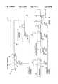
- FIG. 1is a block diagram of a roadway-powered electric vehicle (RPEV) made in accordance with the present invention
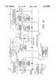
- FIG. 2is a more detailed block diagram of the roadway-powered EV of the present invention.
- FIG. 3is a block diagram of the on-board power director of FIG. 2, and illustrates how the on-board energy storage system of FIG. 2 is preferably realized using a plurality of electromechanical battery (EMB) modules;
- EMBelectromechanical battery
- FIG. 4schematically illustrates a roadway-powered EV system made in accordance with the present invention
- FIGS. 5A and 5Brespectively show a cross section, and an enlarged cross section, of a roadway having a coil embedded therein that serves as the roadway power module of the roadway-powered EV system;
- FIG. 6Adepicts one manner in which only a portion of the roadways over which the roadway-powered EV travels need be energized with roadway power modules;
- FIG. 6Bdepicts the electrification of the roadway at a multi-lane, signalled intersection, where vehicles must often come to a complete stop as they wait their turn to go through the intersection;
- FIGS. 6C and 6Drespectively illustrate electrification of the roadway in clusters, and an enlarged cluster, with clusters being distributed over the length of the roadway;
- FIGS. 7A and 7Brespectively show an overhead, and enlarged cross section, of one manner in which electronic garaging or overnight charging may be realized within a roadway-powered EV system made in accordance with the invention
- FIG. 8depicts a schematic cutaway view of a modular EMB of a type that may be used with the present invention
- FIG. 9Aillustrates an end view of a Halbach array of a type that may be used with the EMB module of FIG. 8;
- FIG. 9Bdepicts the calculated field lines for a quadrant of the Halbach array of FIG. 9A;
- FIG. 10schematically illustrates the various types of communication channels that may be used with the RPEV system of the present invention
- FIG. 11shows a block diagram of the communication channel elements of the invention.
- FIG. 12depicts one type of time-division multiplex scheme that may be used by the communication channel of the invention to transfer data from a plurality of sensors;
- FIG. 13is a block diagram that functionally depicts the automatic garaging features of the invention.
- FIG. 14illustrates how one or more follower (slave) RPEV's may be electronically linked or coupled to a leader (master) RPEV in order to form a "train" of RPEV's;
- FIG. 15schematically illustrates how the power converter used to electrify a charging pad at a passenger loading/unloading zone may also be used to power a plurality of heating coils embedded in the surface structure of the passenger loading/unloading area in order to prevent the formation of ice or the accumulation of snow;
- FIG. 16is a cutaway view of the passenger compartment of an ergonomically-designed multiple occupancy vehicle (MOV) made in accordance with the present invention.
- MOVmultiple occupancy vehicle
- FIG. 17shows a plan view of the passenger seating arrangement in the MOV of FIG. 16.
- the present inventionis directed to a roadway-powered electric vehicle system that includes a network of highways and roadways that have been electrified at select locations, and a fleet of roadway-powered electric vehicles (RPEV's) that traverse the network of highways and roadways and receive their electrical operating power from the electrified highways and roadways.
- RPEV'sroadway-powered electric vehicles
- Many of the components that make up the RPEV system of the present inventionare components that already exist and have been used for other types of EV systems, or other applications. Such components may be found, for example, and are described in the following documents, all of which are incorporated herein by reference: U.S. Pat. Nos.
- FIG. 1there is shown a block diagram of a roadway-powered electric vehicle (RPEV) 12 made in accordance with the present invention.
- the RPEV 12includes a vehicle frame 14 supported by a front suspension system 16, including front wheels 17, and a rear suspension system 18, including rear wheels 19.
- the frame 14 and suspension systemsmay be of conventional design.
- Mounted on the underneath side of the RPEV 14is an onboard power receiving module 20.
- the module 20receives electrical power, symbolically represented by the wavy arrows 22, from a roadway power transmitting module 24 embedded in a roadway 26 over which the RPEV travels.
- the roadway power transmitting module 24receives power from a power conditioner circuit 28, which in turn is connected to a utility power distribution system, such as is provided by a public utility company.
- the utility companyprovides electrical power to most customers as 3-phase, 60 Hz power, at 220 vac. Higher voltages may be made available to some customers, as required, such as 480 volts ac (vac).
- the function of the power converter circuit 28is to convert the 3-phase, 60 Hz power (at whatever voltage is provided) to an appropriate frequency and voltage for driving the roadway power module 24, as described in more detail below.
- Electrical power received from the electrified roadway 26(the term "electrified” is used herein to described a roadway wherein a roadway power module 24 has been embedded) via the onboard power receiving module 20 is stored in an onboard energy storage system 30.
- the poweris directed to such energy storage system 30 through an onboard power control unit 32.
- a power meter 34monitors all electrical power received by the onboard power module 20 so that the utility power company, or other agency, can bill the owner of the RPEV for the cost of such electrical power.
- a key feature of the inventionis performance achieved from the onboard energy storage system 30, described more fully below.
- Such storage systemexhibits a very high energy storage capacity, on the order of 10-15 Kw-h. Further, such energy storage capacity is provided in a very small volume, e.g., on the order of 0.5-1 m 3 , at an extremely low weight thereby providing a very attractive energy density, on the order 20-30 kW-h/m 3 ; a high specific energy, on the order of 150 W-h/kg; and a high specific power, on the order of 5-10 kW/kg. (Note that a conventional electrochemical battery, at best, can only provide a specific power of about 0.2-0.4 kW/kg; and an internal combustion engine only provides about 0.6-0.8 kW/kg.)
- the preferred element of the energy storage system 30is an electromechanical battery (EMB) because it offers a specific power of up to 10 kW/kg, and offers a very high efficiency (power out/power in) on the order of 95% or higher. It is to be understood, however, that the present invention is not limited to the use of an EMB as the energy storage element. Any storage element which offers the specific power, efficiency, specific energy and other criteria set forth herein, may be used with the RPEV system of the present invention. At present, of the available energy storage devices, the EMB appears to best meet the stated criteria, and therefore it is the preferred energy storage element.
- EMBelectromechanical battery
- the RPEV 12also includes an electric drive 36 that provides the motive force for propelling the front and/or rear suspension systems.
- the onboard power control unit 32which is controlled by onboard operator controls 38 and/or automatic control features programmed into the power control unit 32, selectively directs electrical power from the energy storage system 30 to the electric drive 36.
- the electric drive 36, and operator controls 38may incorporate designs and features as are commonly used in existing EV's, e.g., battery-powered EV's, or other EV's, as are known in the art.
- One such feature common to most EV's, and also applicable to the RPEV of the present invention,is that of regenerative braking. Regenerative breaking takes kinetic energy associated with the motion of the vehicle and redirects it back to the energy storage system 30 rather than having such energy be dissipated as heat, or in some other form, whenever it is necessary to brake the vehicle.
- the RPEVreceives its operating power through the electrified roadway 26, i.e., through the roadway power module 24; stores such power in a highly efficient energy storage system 30; and then uses such stored energy, as required, to drive the RPEV's electric drive 36.
- the RPEV 12is all electric and has zero emissions.
- the onboard power control unit 32 of the RPEVincludes a power director 54, a microprocessor controller 56 and various vehicle control units 58.
- the preferred roadway power transmitting module 24is simply a coil 40. Such coil 40 is connected to the power conditioner 28.
- the preferred power conditioner 28is a 3-phase/60 Hz to 1-phase/f1 kHz converter, where f1 is a desired coupling frequency.
- the preferred onboard power receiving module 20is also a coil 42. When a suitable ac electrical current flows through the coil 40 at frequency f1, such current generates a magnetic field that varies at frequency f1.
- Such varying magnetic fieldcuts through the coil 42 and induces a voltage therein according to Faraday's law of induction.
- an ac currentis thus established in the coil 42 and power is effectively coupled from the coil 40 to the coil 42.
- the coupling between the coils 40 and 42is referred to as inductive coupling. It is the same type of coupling that occurs in a transformer, except that in a transformer the two coupled coils are closely physically coupled and are usually on the same magnetic core so that the coupling efficiency between the two coils is very high (i.e., all of the magnetic flux generated by the current in one coil cuts through the other coil). Where the coupled coils have an air gap between them, as occurs for this invention (with the coil 40 being embedded in the roadway, and the coil 42 being carried on the underneath side of the RPEV 12), the coupling efficiency is a function of the distance, or air gap, between the two coils 40 and 42, as well as the relative alignment between the coils.
- the present inventionmounts the coil 42 on a movable assembly 44.
- the horizontal position of the movable assembly 44is controlled by a horizontal coil position unit 46.
- the vertical position of the assembly 44is controlled by a vertical (air gap) coil position unit 48.
- the positioning units 46 and 48, in combination with the steering of the RPEV 12,thus combine to allow the onboard coil 42 to be optimally aligned with the embedded coil 40 so as to provide the maximum possible coupling efficiency between the two coils.
- the air gap between the onboard coil 42 and the embedded coil 40may be reduced to zero, or near zero, by lowering the movable assembly 44 until it contacts the surface of the roadway 26 where the roadway power transmitting module 24 is embedded.
- the RPEV 12is capable of receiving some power from the electrified roadway 12 simply by having the RPEV 12 drive over or on the electrified roadway.
- the embedded coil 40may be continuously energized with an appropriate power signal generated by the power converter 28. Only when the onboard coil 42 comes near the embedded coil 40, however, is significant power transferred through the inductive coupling link. This is because the RPEV 12 represents the electrical load that receives the coupled electrical power. When the load is not present, as when the RPEV is not over the electrified roadway, then there is nowhere for the electrical power to go, and no power transfer (or very little power transfer occurs). This is analogous to having a load, or not having a load, attached to the secondary winding of a transformer. When the load is attached, power is transferred to the load through the transformer. When the load is not attached, no power is transferred to the secondary winding, and no power (other than the power associated with magnetic field losses) is transferred.
- a second way of coupling power from the embedded coil 40 to the onboard coil 42is to incorporate a vehicle sensor 50 into the roadway power module 24.
- the sensor 50senses the presence of the RPEV 12, and in response to such sensing, activates the power converter 28 to energize the embedded coil 40. If the RPEV is not sensed, then the power converter 28 is not turned on. Thus, using such sensor 50, only when an RPEV 12 is present on the roadway 26 is the roadway 26 electrified.
- the sensor 50may be a conventional vehicle sensor that senses the presence of any vehicle driving on the roadway, e.g., a pressure switch sensitive to weight, an inductive strip or loop, or a magnetic or an optical sensor, as are commonly used in the art to sense vehicles and other large objects.
- the senor 50may be a "smart" sensor that senses only RPEV's and not other types of vehicles.
- a smart sensoris realized, for example, by incorporating a conventional rf or optical receiver in the sensor 50 that receives a particular type of identifying signal (rf or optical) that is broadcast by a small transmitter 52 carried onboard the RPEV 12, or by employing an optical scanner as part of the roadway sensor 50 that senses or "reads" a bar code placed on an underneath side of the vehicle as the vehicle passes thereover.
- f1the frequency
- Such electric power frequencyis the dominant system parameter in the RPEV since the alternating current is fundamental to the inductive coupling energy transfer principle, and it affects the size, weight, cost, acoustic noise, flux density and efficiency of the various energy handling systems. Further, the frequency interacts with all of the other system variables in relationships that are generally complex and non-linear. Frequency is thus a basic parameter that appears in the specification for every piece of electrical and electronic apparatus.
- frequencycan be further appreciated by recognizing that heretofore only two standard power frequencies have existed for several decades, one at 50/60 Hz, which is the universal industrial and household standard, and the other at 400 Hz, which is an aircraft standard adopted to reduce size and weight. Neither frequency, however, is optimum for the RPEV system of the present invention.
- a "higher”frequencyin the kHz range, e.g., between 1 and 10 kHz, and preferably between 2 kHz and 3.5 kHz, is the most optimum frequency to use for transferring power through the inductive coupling link and within the RPEV to power the RPEV and to minimize losses.
- the EMBfor example, while operating at variable frequencies, operates at a nominal frequency of around 3000 Hz.
- the strength of the magnetic fields within the RPEVis generally less than 1 mG (milligauss), which is no greater than the background magnetic fields that are present in a typical U.S. home.
- the power meter 34forms an important part of the present invention because it provides a means for a power utility company, or other electrical power provider, to receive payment for the electrical power that it provides to power the RPEV.
- the power meter 34is preferably mounted in such a way so that it is tamper proof and so that it cannot be bypassed, similar to the power meters that are installed in most commercial and residential facilities.
- the power meter 34include means for downloading the power measurements ("power data") that have been made.
- a communication channelthat permits information to be sent to and from the RPEV from a location remote from the RPEV, e.g., via the power transmitting module 24 and other sensors/transducers associated therewith.
- the power data from the power meter 34may be included with the information transmitted from the RPEV. Once downloaded, such power data is preferably directed to the power utility company. The power utility company is then able to bill the appropriate owner of the RPEV for the electrical power that has been used.
- the RPEV 12includes an identification data signal that is transmitted from the vehicle each time that electrical power is coupled thereto when the RPEV is stopped, and therefore when the assembly 44 has been lowered to reduce the air gap to near zero. Before electrical power is transferred, the RPEV identification data signal is verified, and power data is read from the power meter.
- Power received through the onboard coil 42is coupled through a power director 54 to the onboard energy storage system 30. Also coupled to the power director 54 is the electric drive 36. It is the function of the power director 54, as its name implies, to direct power to and from the onboard energy storage system 30 and the electric drive train 36. Power is initially directed, for example, from the onboard coil 42 to the energy storage system 30. Power is also directed, as required, from the energy storage system 30 to the electric drive train 36. Regenerative power may also be directed, when available, from the electric drive train 36 back to the onboard energy storage system 30.
- the power director 54is controlled by the microprocessor controller 56.
- the microprocessor controller 56which is realized using a conventional processor-based system, such as the Motorola 68000 series, or the Intel 386/486 series of processors, both of which are well documented in the art, has appropriate RAM/ROM memory associated therewith wherein there are stored numerous operating routines, or programs, that define various tasks carried out by the controller 56. Many such tasks are the same as are carried out with the operation of any EV.
- the most significant tasks carried out under control of the controller 56relate to directing the power to and from the energy storage system (explained below in conjunction with FIG. 3), controlling the lateral and vertical position of the assembly 44 on which the onboard coil 42 is mounted, receiving appropriate commands from the operator control devices 38, and monitoring onboard vehicle sensors 60.
- the operator control devices 38include both operator control input devices 62 and vehicle displays 64.
- the input control devicesinclude, e.g., manual switches or controls that determine speed, direction, braking, and other controls, associated with the manual operation or driving of the RPEV. Such devices are of conventional design and operation.
- the displays 64are also of conventional function and design, indicating to the operator such parameters as vehicle speed and the status of the energy storage system 30.
- the operator input control devices 62generate input signals to the microprocessor controller 56.
- the microprocessor controller 56responds to such input signals by generating appropriate output signals that are directed to a set of vehicle control units 58.
- the vehicle control units 58perform the function of interface (I/F) units that convert the signals output from the controller 56, which are digital signals, to the requisite signals for actually effectuating the desired control.
- I/Finterface
- a braking signalmay be sent from the operator control 62 to the processor controller 56.
- the processor controller 56would process the braking control signal in an appropriate manner relative to the current status of the RPEV, e.g., speed, direction, etc., as determined by the vehicle sensors 60, and would determine the appropriate amount of braking needed.
- a braking control unitone of the control units 58
- the analog braking signalis then directed to a conventional braking mechanism, i.e., a hydraulic control pump, that would apply the appropriate hydraulic pressure to the vehicle's braking system. Similar processes are carried out for driving the vehicle at a desired speed, steering the vehicle, and the like.
- RPEV “driving" functions of the RPEValthough normally under manual control of the operator through the operator control devices 38, may also be automated, or controlled by the controller 56 in accordance with a prescribed or preprogrammed regime.
- a key feature of the RPEV of the present inventionis to incorporate lateral, as well as vertical (air gap) positioning of the assembly 44 on which the coil 42 is mounted.
- the operator of the RPEVapproaches, e.g., a passenger loading/unloading zone, he or she activates an auto-positioning control that effectively "takes over" the driving of the vehicle for the final 10-15 feet.
- the vehicle sensors 60sense the position of the RPEV 12 relative to the roadway power transmitting module 24 embedded in the roadway.
- the steering of the vehicleis then controlled by the microprocessor controller 56 so that the vehicle is laterally positioned, to within a rough tolerance, e.g., ⁇ 5-10 cm, of the optimum lateral position when the vehicle comes to its designed stopped location.
- the horizontal coil positioning unit 46typically realized, e.g., using conventional hydraulic and/or electronic positioning devices, further controls the lateral position of the coil 42 so that it is more closely aligned, e.g., to within ⁇ 1-2 cm, of the optimum lateral position.
- the vertical (air gap) positioning unit 48also typically realized, e.g., using conventional hydraulic and/or electronic positioning devices, lowers the assembly 44 so as to reduce the air gap to near zero.
- the onboard energy storage system 30With the air gap near zero, the onboard energy storage system 30 is charged with additional power obtained from the power converter 28 through the inductive coupling link (which operates at maximum efficiency with a near zero air gap).
- the vertical positioning unit 48raises the assembly 44 back to its normal position on the underneath side of the RPEV frame.
- the vehicle sensors 60comprise a variety of different types of sensors that sense all of the parameters needed for proper operation of the RPEV. Such sensors sense, e.g., temperature, lane position, distance from nearest vehicle or object, and the like. For purposes of laterally positioning the assembly 44, such sensors are typically optical sensors that look for markers placed on the roadway power transmitting module 24 embedded in the roadway. Other types of sensors may also be used for this purpose, including acoustic, mechanical, and electromagnetic sensors.
- the lateral (horizontal) positioning device 46When the RPEV is traveling (being driven) on an electrified portion of a highway or roadway, the lateral (horizontal) positioning device 46 is also activated so that the coil 42 can maintain, to within a rough tolerance, an optimum lateral position relative to the coil 40 that is embedded in the roadway.
- the approximate lateral positionmay be determined by monitoring the change in the amplitude of the inductively received power signal as the coil 42 is laterally moved in one direction or the other.
- the processor controller 56then laterally positions the coil 42, using the horizontal coil positioning unit 46 and/or the steering of the RPEV, to maintain the coil 42 at a lateral position that keeps the induced power signal at a peak or maximum level.
- FIG. 3a block diagram of the onboard power director 54 and the onboard energy storage system 30 is shown.
- the preferred onboard energy storage system 30comprises a plurality of electromechanical battery (EMB) modules, labeled EMB-1, EMB-2, . . . EMB-n.
- EMBelectromechanical battery
- the power directorincludes a switch matrix 70, a unidirectional ac-to-ac converter 72, and a bidirectional matrix converter 74.
- the bidirectional matrix converter 74is connected to the electric drive train 36, which includes one or more ac induction drive motors 76.
- the ac-to-ac converter 72is connected to the onboard receiving coil 42 through which inductively coupled electrical power is received.
- Each EMBincludes three power terminals, representing the 3-phase signals that are applied thereto (when the EMB is being charged), or extracted therefrom (when the EMB is acting as an ac generator).
- a set of switches, one set for each EMBconnects each power terminal of each EMB to either the ac-to-ac converter 72 (when electrical power is being applied to the EMB to charge it) or the matrix converter 74 (when electrical power is being extracted from the EMB and applied to the induction drive motors 76 that form part of the electric drive train 36; or when regenerative electrical power is being applied back to the EMB from the motors 76).
- the unidirectional ac-to-ac converter 72is of conventional design.
- the power signal received through the coil 42comprises a single phase, e.g., 3000 Hz signal. This signal is rectified, and then chopped with an appropriate frequency control signal(s), provided by the microprocessor controller 58, to create a 3-phase signal of varying frequency.
- Each phase of the 3-phase signal thus generatedis applied to the switch matrix 70 so that each phase may, in turn, be selectively applied to the respective input terminal of each EMB of the energy storage system.
- Each EMBis charged (energy is stored therein) by applying a 3-phase signal thereto that causes the rotor of the EMB to spin at the frequency of the applied signal.
- a rotating magnetic fieldis established within the EMB that rotates at a rate of 3000 revolutions per second, or 180,000 revolutions per minute (rpm). If the rotor is stopped when such a signal is applied, then it spools up to the speed corresponding to the applied frequency, representing the storage of energy. If the rotor is rotating at a speed less than the speed corresponding to the applied frequency, then the rotor speed increases to match the speed dictated by the applied frequency, representing the storage of additional energy.
- the key to spooling up, or charging, a given EMB to increase the energy stored thereinis to apply a signal thereto having a frequency corresponding to a rotor speed that is greater than the present rotor speed.
- each EMBincludes a means 31 for determining its rotor speed, shown functionally in FIG. 3 as the speed sensors 31-1, 31-2, . . . 31-n.
- Each of the speed sensors 31-1, 31-2, 31-nis coupled to the controller 56 through a suitable bus 33.
- the bidirectional matrix converter 74performs the function of taking the 3-phase signals generated by each EMB (when functioning as an energy source, or generator) and converts such signals as required in order to drive the ac induction motors 76 included in the electric drive train 36.
- the matrix converter 74also performs the function of taking any energy generated by the motors (which, when the RPEV is braking or coasting, are really functioning as generators) and reapplying such energy to the EMB's of the energy storage system 30.
- the matrix converter 74may be as described, e.g., in Ziogas, et al., "Analysis and Design of Forced Commutated Cycloconverter Structures with Improved Transfer Characteristics", IEEE Trans. Ind. Elec. Vol. IE-33, No. 3, 271 (Aug. 1986).
- the switch matrix 70performs the function of a plurality of switches that connect the set of power terminals of each EMB to either the matrix converter 74 or the ac-to-ac converter 72.
- Such switch matrixmay take various forms, including electrical relays, solid state switches, SCR's, diodes, and the like.
- each individual EMBmay be of a standard size and design.
- a conventional EMBfor example, is designed to provide an energy capacity of 1 kW-h. By using fifteen such EMB modules in parallel, as shown in FIG. 3, the overall energy capacity thus increases to 15 kW-h.
- RPEV'sFor smaller, lighter, RPEV's, only a few EMB's are needed to power the vehicle, e.g., 2-6.
- more EMB'sare needed, e.g., 6-10, or more.
- RPEV'ssuch as buses, further EMB's are added as required, e.g., 12-20, or more.
- FIG. 4there is shown a schematic illustration of a roadway-powered electric vehicle (RPEV) system made in accordance with the present invention.
- the RPEV systemincludes a network of roadways and highways 26, selected portions of which have been electrified with a roadway power transmitting module 24, over which a fleet of RPEV's 12 may travel.
- Each power transmitting module 24is connected to a utility power source over suitable power lines 78, as previously described.
- the roadway power transmitting modules 24are typically about 3 meters in length. For many locations of the roadway/highway network, a single module 24 is all that is required in order to efficiently couple to an RPEV that is above it. At other locations, e.g., along a section where there is no planned stopping of the RPEV's, such as areas 88 and 90, several modules 24, laid end-to-end, will be needed. Thus, at parking locations 82, or in an overnight parking garage area 84, or even at a passenger loading/unloading zone 86, and other locations where it is anticipated that the RPEV will be stopped for a sufficient charging time, a single power transmitting module of 3 meter length is all that should be needed.
- a shortened (e.g., 1-2 meters) power transmitting module 24'can normally be employed and still provide adequate coupling with the parked RPEV.
- various sensors 80may be positioned to provide an indication of roadway surface conditions. Such information may be transmitted to the RPEV's 12 through conventional means, e.g., rf transmission; or through modulation of the power signal transmitted over the primary power line 78 and inductive coupling link with each vehicle.
- FIGS. 5A and 5BA cross-sectional view of the roadway power transmitting module 24 is illustrated in FIGS. 5A and 5B, with FIG. 5B showing an enlarged view of the section of the roadway that is circled in FIG. 5A.
- the preferred width of the coils 40 and 42is about 65 cm, as seen in FIG. 5B, with the coil being centered in a typical lane of about 3.65 meters in width, as seen in FIG. 5A.
- Both the embedded coil 40 and the onboard coil 42may be characterized as "flat" or “pancake” coils that lie in respective planes that are parallel to the surface of the road 26.
- a conventional battery-driven electric vehicleis normally charged overnight for several hours in one's garage, and then the vehicle starts off the day with a full charge on the batteries.
- the rate of chargeis inherently constrained by limitations of power available in the typical household, since 200 KW, if installed, would be prohibitively expensive.
- the rate of charge in the homeis thus limited to 6 KW to 10 KW, which means that a typical recharge takes several hours.
- the idea of opportunity chargingtakes on a whole new meaning.
- opportunity chargingis so different for the RPEV system, a new term has been coined, "demand charging” or “demand responsive charging,” to signify the difference.
- Demand responsive chargingis, as previously explained, made possible by two technologies: (1) the non-contacting inductive coupling energy transfer system, and (2) an energy storage system that allows a very high rate of charge to take place.
- the combination of these two technologies and the associated onboard power control unit 32make it possible to replenish the stored energy of an RPEV in minutes, not hours.
- At least four types of demand responsive chargingare possible with the RPEV system, described below.
- a first type of demand responsive chargingis charging of electric buses, using inductive coupling pads, at about 25 percent of its stops. Such charging transfers enough energy for the bus to run continuously for 24 hours a day, if necessary, since the energy storage system is being constantly replenished. This means that for a bus system less than 1 percent of the route would need to be electrified, contrasted with the trolley bus, which has 100 percent electrified. From a cost standpoint, this means that a bus line can be electrified for less than 4 percent of the cost of overhead wires. It makes a practical electric bus possible for the first time.
- the energy transfertakes place for a 20 second to 30 second period when the vehicle is fully stopped, thus the air gap can be zero, or nearly zero, thereby greatly improving the efficiency as well as the rate of power collection.
- a representative electrification of a bus stop along a highway routeis shown at area 86 in FIG. 4.
- using such demand responsive charging system for a bus line as described abovemakes possible an all-electric bus system that is competitive with a diesel bus in life cycle costs.
- a bushas assigned layover points where it must wait for a few minutes in order to synchronize its route with an advertised schedule.
- a charging pad 24may be installed at the layover point, and the RPEV bus could get enough energy replenishment in 3 to 5 minutes to run much of its assigned loop or route without the need for further energy transfer.
- a second type of demand responsive charging for use with the RPEV system of the present inventionis that of automobile and highway, and depicted in FIG. 6A.
- an effective electrification systemwould require the heavily traveled freeway lanes to be fully electrified, i.e., at least one lane in each direction for even a thin network in a region. In the San Diego region, for example, this would mean about 500 lane-kilometers (312 lane miles) would need to be electrified if one established an electrification network on the freeways.
- the RPEV system of the present inventiononly about 10 percent of the powered lane actually needs power, with the remaining 90 percent being unpowered, as shown schematically in FIG. 6A.
- the RPEVwhen the RPEV travels over the 10% of the lane that is electrified, it is charged, which charge provides sufficient energy for it to travel the remaining 90% to the next electrified location.
- a large safety factoris designed into the RPEV so that it has the capacity, when fully charged, to travel much further than the 90% distance to the next charging location.
- the RPEVreceives a charge as it is traveling over electrified portions of the roadway. From a system specification standpoint, minimum power transfer rates of 100 to 140 kW in motion, or roughly 30 to 50 KW/m, are desirable.
- FIGS. 6C and 6DA variation of the demand responsive charging system shown in FIG. 6A is depicted in FIGS. 6C and 6D.
- the roadway power transmitting modules 24(charging pads) are spaced about every 300 m over a distance of, e.g., 1.2 km, and are thus grouped in clusters 25 of five modules 24 each, with each cluster 25 being powered from the same power conditioner 28.
- the clusters 25are then selectively spaced along the length of the roadway, e.g., with a non-electrified section of roadway of about 3.6 km separating the clustered sections.
- a new cluster of power transmitting modules 24is found about every 4.8 km of the roadway.
- a third type of demand responsive charging for use with the RPEV systemis that of selective electrification of a signalized arterial intersection, as shown in FIG. 6B.
- FIG. 6Bwhich shows an aerial view of a typical intersection
- the electrified portions of the intersectionsi.e., those that have the roadway power transmitting modules 24 embedded therein, are shaded.
- All RPEV's 12 passing through the signalized arterial intersectionare able to take advantage of demand responsive charging.
- the typical transit time through the intersectionis about 45 seconds to 60 seconds. During this time, the RPEV receives as much energy from the roadway module 24 as it could in a mile of a powered lane on the highway.
- 2% of the arterial lane being electrifiedhas the same effect as fully electrifying the lane.
- a fourth type of demand responsive charging that may be used with the RPEV systemis that of electric garaging.
- a charging pad 24'approximately 1 meter square and 3 cm thick, is installed on the surface of a driveway or garage floor, as shown in FIGS. 7A and 7B.
- the pad 24', and associated power conditioner (power supply) 28'are capable of operating in two modes.
- low levels of continuous energy flowe.g., 200 watts to 500 watts, are provided.
- Such energy flowis used to provide a stable interior temperature in the RPEV 12 from about 50° F. to 70° F. corresponding to cold or hot climates.
- the RPEVcommands the rate of energy flow according to its need to regulate interior temperatures, and is thermostatically controlled.
- the energy transfer system for the electronic garaging first modeis preferably actuated remotely a few minutes in advance of use to bring interior temperatures to a comfortable level, and a data link between the roadway and vehicle will provide security against tampering or theft.
- the mechanical gap between the vehicle pickup coil 42 and the roadway element 24'is adjusted to essentially zero in this mode of operation, as well as in the static charging mode described next.
- the pad 24'is used for an overnight recharging of the energy storage system 30 of the RPEV 12.
- the power flow levelsare between 6 KW and 10 KW (comparable to an electric clothes dryer in a residence), and the time for recharge ranges from 1 hour to 2 hours.
- the electronic garagingoperates in a demand responsive mode, and is fully automated and hands-off for the driver.
- the RPEVgenerates an enabling signal to carry out the charging at times of day when utility rates are lowest, e.g., at 2:00 a.m., turning it off when the energy storage is replenished.
- a pressure sensor 162senses the presence of a vehicle 12' parked above the charging pad 24'.
- a receive coil 164(which may function as the sensor 50 (FIG. 2) may further be used to verify the identity of the vehicle 12'.
- a charging control circuit 166controls when the power conditioner 28' is allowed to charge the charging pad 24' and at what charging level.
- a clock circuit 168provides an indication to the control circuit 166 of the time of day so that the high level charging mode can occur when the electric rates are the lowest.
- a communication receiver 170is attached to the control circuit 166 so that the low level charging mode (used, e.g., to bring the interior of the vehicle 12' to a comfortable temperature) may be invoked on command.
- the owner of the garaged vehiclefor example, may invoke the low level charging mode using a remote transmitter, similar to a garage door opener transmitter; or by throwing a remote switch that is electrically coupled to the receiver 170.
- the RPEVmay issue an enabling signal to command the energy transfer to take place, depending on the energy storage requirements at that moment.
- a high rate of energy transfer for a short periodis preferred, if possible.
- the systemis charged only as needed and as requested or demanded, hence the term "demand responsive charging" properly describes the charging action that takes place.
- FIG. 8a schematic cutaway view of a modular EMB 31 of a type that may be used with the present invention is illustrated.
- An EMB module 31 of the type shown in FIG. 8is described more thoroughly in Post et al., "A High-Efficiency Electromechanical Battery,", Proceedings of the IEEE, vol. 81, No. 3, pp. 462-474 (March 1993).
- the EMB module 31includes a rotor 103 mounted for rotation on magnetic bearings 100 and 102 within a sealed vacuum chamber 97.
- the sealed vacuum chamber 97is defined by thin stainless steel walls 94, reinforced with fiber composite, and a glass ceramic sleeve 95.
- the entire vacuum chamber 97is then mounted inside of a containment vessel 92 made of highly impact-resistant material, such as three-dimensional fiber composite.
- Appropriate gimbal mounts 98(represented as springs) are used to mount the vacuum chamber 97 within the vessel 92.
- Three-phase, stationary, generator windings 96are mounted outside of the vacuum chamber 97, between the thin walls 95 that define a narrow neck portion of the vacuum chamber. Each winding terminates at one of three terminals 99.
- the rotor 103is made from concentric rotating cylinders 104, 106, 108 and 110.
- the concentric cylindersare made from thin walls (10% of the radius) to prevent delamination, and are separated by an elastic material 109.
- a magnet array 111is placed on the inside of the inner concentric rotor cylinder 110 to create a rotating dipole magnetic field.
- the rotor 103rotates at a velocity of the order to 10,000 rads/s, and allows each EMB module to produce about 1 kW-h of energy.
- the EMB module 31stores more energy per unit mass or per unit volume than other known energy devices. This is because stored energy increases only linearly with the mass of the rotor (for a given geometry), but goes up as the square of its rotation speed. Since the rotor 103 is made of a light, strong material, it can be spun much faster than heavy strong material (commonly used in conventional mechanical flywheels) before centrifugal forces threaten to break it up. The result is that the EMB can store much more energy, and more safely, than has previously been possible.
- Composite materials based on graphitemake it possible to build the EMB with a specific energy of about 150 Wh/kg, and a specific power that is orders of magnitude greater than anything achievable by an electrochemical battery or even an internal combustion engine. As indicated previously, the EMB can deliver a specific power 5,000 to 10,000 W/kg.
- the rotor 103runs on magnetic bearings 100 and 102 in the vacuum chamber 97, realized, e.g., using permanent magnets made from Nd-Fe-B.
- Such bearingsoffer the added advantage of extending the EMB's life since there is no mechanical contact, and hence no wear, with this mode of suspension.
- the sealed EMBhas an extremely long lifetime, and should outlast the vehicle in which it is carried.
- the vacuum chamber 97is evacuated to a pressure of 10 -3 to 10 -4 pascals. To achieve and maintain a vacuum of that pressure, it is important that the rotor materials minimize vacuum outgassing, and that other materials employ modern getter alloys.
- the rotor materialsare selected and designed to fail by disintegrating into a mass of fairly benign fluff or "cotton candy".
- massive steel rotorssuch as are used in mechanical flywheels, may fail in spectacular fashion, throwing off large chunks of shrapnel.
- the vessel 92also made of a three-dimensional composite, is able to readily contain any such disintegrating mass by incorporating into its design high-strength fibers that run in all three directions. With such construction, any cracks that get started in the housing are not able to propagate.
- the EMBis ironless. This feature not only keeps the weight low, but prevents hysteresis losses common in iron systems. Moreover, since inductances of the multi-phase windings are extremely low (with no iron present), and since rotation speeds are high, unusually high peak power outputs are achievable, with stator copper losses that can readily be handled by conventional means (air or liquid cooling).
- a central feature of the EMBis the generator/motor design.
- a special array of permanent magnet bars 112is mounted on the rotor at 109 (FIG. 8).
- An end view of such arrayknown as the Halbach array, is shown in FIG. 9A, with the arrows indicating the relative polarity of the bar magnets 112.
- the magnetic lines of force associated with one quadrant of such arrayare shown in FIG. 9B.
- Of significanceis the uniformity of the interior field, and its near cancellation outside of the array.
- Nd-Fe-B magnetshaving a B r equal to 1.25 Tesla, dipole fields of the order 0.5 T can be readily obtained.
- a typical EMB module of the type shown in FIGS. 8, 9A and 9B,provides the following operating parameters:
- the EMBis the preferred energy storage device for use with the RPEV of the present invention because the EMB offers specific power and specific energy that makes it a viable energy source for an electric vehicle.
- alternative energy sourcesare developed, offering the same of similar performance relative to their specific power and specific energy, such alternative energy sources may also be used with the invention.
- FIG. 10the communication channel provided as part of the RPEV system will be described. It is noted that several different types of communication channels are illustrated in FIG. 10, any one, or any combination of which, may be used with the invention. Hence, not all of the elements shown in FIG. 10 are needed for a given type of communication channel, but all such elements are nonetheless shown in FIG. 10 in order to reduce the number of figures that might otherwise be needed.
- a first type of communication channel useable with the inventionis used to broadcast roadway conditions to the RPEV before the RPEV encounters such conditions.
- Such an early roadway-condition warning systemincludes a plurality of roadway sensors 80 that are selectively positioned along the roadway 26, e.g., at the same locations where the charging pads 24 (also referred to as the roadway power transmission modules) are located. Typically, such roadway sensors will be located at least 300 m apart, and may be much farther apart, e.g., 1 to 5 km.
- the roadway sensors 80detect the condition of the surface of the roadway 26, and other environmental parameters of interest. Typically, the sensors 80 sense at least whether there is any moisture or ice on the roadway surface, and may also sense the temperature of the roadway surface.
- Each roadway sensor 80is connected to an appropriate sensor driver circuit 122 that provides the sensor with whatever electrical signals it needs to perform its sensing function. For a moisture/temperature detector, such signals typically include just a current pulse of a few ma.
- the sensor driver circuit 122after determining the measured parameter, encodes this information to create a sensor signal, or sensor word.
- the sensor wordin addition to the measurement of the moisture/temperature, also includes an identification number to identify the particular sensor 80 from which the sensor signal originated. Alternatively, the sensor signal may be transmitted in a time-division multiplex scheme that uniquely identifies the sensor from which it originated.
- the sensor wordis provided to a transceiver (xcvr) circuit 124.
- the roadway sensor 80 and corresponding sensor drive circuit 122are of conventional design.
- the transceiver circuitfunctions as a transmitter and provides the sensor word to a power modulator/demodulator circuit 126.
- the power modulator/demodulator circuit 126is coupled to the main power line 130 that provides the primary power to the power conditioners 28 and to the output of the power conditioner (PC) 28 that provides the 1-phase, 3000 Hz (nominal), signal to the charging pad 24.
- the information signalis superimposed with the power signal on the power line, or is otherwise merged with the power signal, so that the power line conductor passes both the information signal and the power signal.
- the manner of superimposing an information signal on a power signal, or modulating a power signal with an information signalis known in the art. (See e.g., the security system art, where the ac power lines of a protected structure are also used to interconnect individual sensors with a central monitoring device.)
- the main power line 130thus functions as the medium, or communications channel, through which sensor signals may be transmitted from one power modulator/demodulator 126 to another.
- Each power modulator/demodulator 126further couples the signals stripped off of the main power line to the respective charging pads so that such signals may be coupled into each RPEV as it travels over the respective pad 24.
- an additional power modulator/demodulator circuit 132, and a corresponding transceiver circuit 134couple the sensor signals, and any other signals that may be on the communication channel (the main power line 130) to a communication control and monitoring station 136.
- the station 136thus functions as a communication center for the RPEV system.
- the RPEV 12upon being charged with a power signal through the charging pad, also receives the sensor signals from the various sensors along the roadway 26. Once received, the sensor signals are processed (using the onboard processor 56) and acted upon. Typically, the information contained within a sensor signal is at least displayed, e.g., "sensor No. xx, located at point yy on the roadway, reports ice and/or moisture," and may also be factored into any automatic controls that may come into play when that portion of the highway is reached.
- An additional type of communication channelthat may be used with the invention is as described above, but further uses an existing or dedicated communication line 138 to tie the various transceiver circuits 124 together and to the communication control and monitoring station 136.
- Existing communication lines that may be used as the line 138include telephone lines, cable TV lines, and the like.
- a dedicated coax communication lineinstalled between each power transceiver unit 124, would be economically viable to serve the function of the communication line 138.
- a further type of communication channelmay be established by embedding into the roadway 26 a wire loop 140 that effectively serves as an antenna to couple signals to the RPEV 12 at all locations along the roadway where the charging pads 24 are not located, e.g., at all non-electrified roadway sections. (At electrified locations, signals may be coupled to the RPEV through the charging pads, as described above.) Such loops 140 may be coupled to the same input power lines that charge the respective charging pads. In those locations where there is not a charging pad, e.g., where the wire loop is some distance from a charging pad, a separate transceiver 124' may be connected directly to the wire loop 140. Such transceiver 124' is then coupled to a power modulator/demodulator circuit 126' (when used), or to the communication line 138.
- the availability of the wire loop 140allows continuous communications to be had with the RPEV regardless of where it may be located along the network of roadways and highways. Hence, telephone, video and other signals may be readily accessible within the RPEV as it travels along a route having the wire loop 140.
- the wire loop 140may be installed or embedded within the roadway 26 without great expense. In most instances, all that is required is to grind, cut, or etch a small groove or channel in the roadway surface, lay down a suitable conductor within the groove or surface, and cover or seal the groove or channel with tar, pavement, or other suitable filler.
- the RPEV 12may also carry onboard a conventional rf transceiver 142 that, through a suitable antenna 144, is in telecommunicative contact with the communication control and monitoring station 136, which also has an antenna 146.
- rf telecommunication channelsare well known and used in the art, but suffer from degraded reception and transmission in areas where there are mountains, buildings, or other structures or obstacles that interfere with the rf channel.
- Such communication channelmay be used to both send and receive information to and from the RPEV.
- a particular RPEVmay periodically send an identification signal that identifies that RPEV, and the location whereat the signal is received along the communication channel thus provides a way for the communications center 136 to "track" the RPEV.
- Such a “tracking" featureis of significant benefit for fleet management purposes.
- the ability to send signals to and receive signals from the RPEVit is possible to completely control its operation from the communications center 136, thereby obviating the need to have a driver onboard the RPEV where the RPEV's are used, e.g., as a mass transit type of system, or as a cargo delivery system.
- FIG. 11a functional block diagram is shown of one manner in which the communication channel interface with the RPEV 12 may be realized.
- Many of the elements shown in FIG. 11are the same as those of FIG. 2, although many of the elements of FIG. 2 have been omitted from FIG. 11 for clarity.
- the embedded coil 40 and the onboard coil 42are shown, as has been previously described.
- Coil 40inductively couples the 1-phase power signal to the onboard coil 42.
- Such power signalmay be modulated with the information signal that is to be transferred to the RPEV.
- the power signalwhen received within the RPEV, it is demodulated (stripped away from the power signal) using an onboard modulator/demodulator circuit 150, then processed as needed (e.g., converted to an appropriate form) by a receiver circuit 152, and presented to the onboard microprocessor controller 56.
- an information signalmay be sent to the RPEV.
- an information signalWhen an information signal is to be received from the RPEV, such signal originates in the onboard microprocessor controller 56 and is presented to an appropriate onboard transmitter circuit 154, which may be of conventional design, that converts the signal to an appropriate form for transmission.
- the signalis then presented to the onboard modulator/demodulator circuit 150, where it is modulated in an appropriate manner and presented to coil 43.
- Coil 43inductively couples the signal to embedded coil 41.
- Coil 41then presents the signal to communication receiver 124.
- Communication receiver 124then couples the signal directly to the communication line 138, or to the power modulator/demodulator 126, which couples it to the main power line 130.
- coils 40 and 41are shown in FIG. 11 to perform the sending and receiving functions, respectively, at the embedded location, and corresponding coils 43 and 44 are shown that perform the sending and receiving functions onboard the RPEV, in practice the coils 40 and 41 may be the same coil, as may the coils 43 and 44.
- FIG. 12illustrates one manner in which the sensor signals, obtained from all the various roadway sensors 80 that may be located along the length of the roadway 26, and other signals transmitted to and from the RPEV over the communication channel, are multiplexed so that the signals are not confused and intermingled with each other.
- the multiplex scheme depicted in FIG. 12is that of a time division multiplex scheme. In accordance with such scheme, all that is required to perform the multiplexing function is to assign a specific time when a certain identified signal is to be sent or received. Such time division is easily accomplished simply by counting cycles of the power signal.
- a synchronization pulse 160is generated by the utility company, or otherwise superimposed on the main power signal, every second.
- a power signalthat operates at a frequency of 60 Hz
- Each of these cyclesis assigned a certain function depending upon its location relative to the sync pulse 160.
- the odd cycles following the sync pulsei.e., the 1st, 3d, 5th, 7th, . . . cycles are assigned for transmission; and the even cycles following the sync pulse, i.e., the 2nd, 4th, 6th, 8th, . . . cycles are assigned for receiving.
- the first 12 cyclesmay be reserved for general communication functions in this manner.
- the remaining 48 cyclesmay be assigned to 48 respective sensors, with a first sensor (at a first known location on the roadway) inserting (superimposing) its sensor signal on the power signal during the 13th power cycle, a second sensor (at a second known location on the roadway) inserting its sensor signal on the power signal during the 14th power cycle, and so on. If there are more than 48 sensors to be monitored, then the multiplexing capacity may be increased by either increasing the duration between the sync pulses, e.g., to 2 sec., and/or counting half cycles of the power signal instead of full cycles.
- the concept of electronically linking a plurality of RPEV's together in order to form a "train” of such vehiclesis illustrated.
- the RPEVmay be totally controlled electronically, as a robot, because its controls are all amenable to simple commands, e.g., drive forward at a certain speed, steer left or right, brake, etc. Nonetheless, because the RPEV is constantly in traffic, and not all circumstances can be foreseen, it is usually desirable to have a real person onboard that can operate the vehicle, even though such person may, on occasion, place the vehicle in an "auto pilot" mode.
- a lead RPEVtermed the "master” on which a live person operator is located, may generate the electronic signals that are used to control one or more following RPEV's, termed the "slave".
- the master/slave RPEV systemis depicted in FIG. 14.
- a master RPEV 172leads two slave RPEV's 174 and 176.
- the coupling of the electronic control signals from the master 172 to the slaves 174 and 176is by way of a flexible, coiled cable 178 that simply plugs into both RPEV's.
- Such cablebears no mechanical tension as each RPEV has its own source of power, and is independently charged through the network of charging pads 24.
- a master RPEV 180leads a slave RPEV 182 with the electronic coupling being provided by a flexible, coiled cable 178, as previously described, and with an rf link, represented in the figure by the antennas 184 and wavy arrow 186.
- the rf linkis used to provide a redundant link (used to provide added safety) through which the proper command signals may be received by the slave vehicle.
- FIG. 15a further enhancement of the RPEV system of the present invention is schematically depicted.
- the charging pad 24is located at a curbside designed for a passenger loading/unloading zone.
- the charging pad 24is powered from a power conditioner 28 as previously described.
- Also powered by the power conditioner 28are heating coil pads 188.
- the heating coil pads 188are embedded in the sidewalk, or other surface material, that surrounds the passenger loading/unloading zone.
- the purpose of the heating coil pads 188is simply to melt any ice or snow that might otherwise accumulate at the loading/unloading zone, thereby providing a further convenience and measure of safety for the passengers.
- the heating coils 188are not heavy consumers of electrical power, but operate using only about 200-400 W each. Thermostatic control of the heater coils may be used to maintain the surface temperature around the coils to within a desirable range.
- a further important feature achievable with the RPEV system of the present inventionis the ergonomic design of the passenger compartment of a multiple occupancy vehicle (MOV) that includes the RPEV features previously described.
- An MOV 13is shown, partially cutaway, in FIG. 16.
- the MOV 13is a unique, low-floor automobile-sized vehicle. That which is shown in FIG. 16 is for an all-seated version for 15-17 passengers, plus an operator.
- the plan view of the seating arrangement for such MOVis shown in FIG. 17.
- a standing version of the MOVmay also be used.
- the MOVis adapted for traveling on the electrified roadway described herein. It is charged at stops using a demand responsive charging mode, also as previously described. It is an all electric vehicle, and utilizes electronic guidance at pullouts to assure good alignment between the coupling coils. It may be coupled electronically with other vehicles, as described in connection with FIG. 14 above.
- the MOV 13has a door system that allows easy ingress and egress with sufficient head room to avoid bumping one's head.
- the door systemincludes two components, a sliding door 190 and an upper door 192. When open, the sliding door exposes two entries 194 and 196, and the upper door 192 raises to provide increased head room.
- the entry 194allows passengers access to a front curved row of six seats 198, seen best in the plan view of the MOV in FIG. 17.
- the entry 196allows passengers access to a second curved row of five seats 200, and a rear L-shaped bench 202.
- the rear bench 202can seat 4-6 adults comfortably.
- An important aspect of the MOV 13 shown in FIGS. 16 and 17is a low floor, which facilitates platform loading (no stepping down or stepping up is required). Platform loading is a big advantage to the handicapped, and makes loading/unloading easier for everyone.
- the present inventionprovides an efficient, viable, safe, roadway-powered all electric vehicle that uses, with only minor modification, the existing network of highways, roadways, and/or garaging/parking facilitates that are already in place to service ICE vehicles.
- the RPEV system disclosedprovides a zero-emission electric vehicle system wherein the RPEV's of the system may be recharged while such RPEV's are in operation within the system. Hence, the RPEV's need not be taken out of service from the system in order to be recharged, as is common with prior art battery-storage type EV's.
- numerous additional featuresmay be used to enhance the RPEV system, such as the inclusion of: (1) an onboard power meter; (2) a wide bandwidth communication channel to allow information signals to be sent to, and received from, the RPEV while it is in use; (3) automated garaging that couples power to the RPEV for both replenishing the onboard energy source and to bring the interior climate of the vehicle to a comfortable level before the driver and/or passengers get in; (4) electronic coupling between "master” and "salve” RPEV's in order to increase passenger capacity; (5) inductive heating coils at a passenger loading/unloading zone in order to increase passenger safety; and (6) an ergonomically designed passenger compartment in which passengers may travel safely and comfortably.
Landscapes
- Engineering & Computer Science (AREA)
- Power Engineering (AREA)
- Transportation (AREA)
- Mechanical Engineering (AREA)
- Life Sciences & Earth Sciences (AREA)
- Sustainable Development (AREA)
- Sustainable Energy (AREA)
- Electric Propulsion And Braking For Vehicles (AREA)
- Charge And Discharge Circuits For Batteries Or The Like (AREA)
- Current-Collector Devices For Electrically Propelled Vehicles (AREA)
Abstract
Description
TABLE 1 ______________________________________ Specifications of Typical Roadway-Powered Multiple Occupancy All Electric Vehicle Item Description ______________________________________ UTILITY POWER 480 vac, 60 Hz, 3-phase POWER CONDITIONER Input: 480 vac, 60 Hz, 3-phase Output: 225 kW, 3 kHz, 1-phase ROADWAY POWER 3 kHz, 300 amps, 200 kW. TRANSMITTER MODULE Module Length: 3 meters ONBOARD POWER 3 kHz, 200 kW; Mounted on RECEIVING MODULE movable assembly to provide multiple pickup positions ONBOARD POWER Functions: Motor Controller; CONTROLLER Regeneration Management; Pick- up Power Control; Onboard Energy Storage Control; Monitoring State of Change; Metering Energy Consumption ONBOARD ENERGY 15 kW-h (15 1 kW-h modules STORAGE @ 10 kW each, 3 kHz (nominal) ELECTRIC DRIVE TRAIN Two 35 kW AC Motors MULTIPLE OCCUPANCY 10-15 seated passengers; 110 km/ VEHICLE (MOV) DESIGN h max speed; low floor; platform FEATURES loading; electric propulsion; electronic guidance; electronic coupling. ONBOARD CONTROL Functions: electronic steering; SYSTEM lateral guidance control; electronic coupling and platform control; vehicle diagnostics; vehicle ID; "throttle" control; brake control; speed profile control; route control; vehicle "flight recorder". ROADWAY CONTROL Functions: roadway-vehicle ELEMENTS communication; lateral guidance signal; speed markers; vehicle ID interrogation; roadway surface condition sensors. ______________________________________
______________________________________ Rotation speed: 200,000 rpm Magnetic field of Halbach Array: 0.5 T Length & Width of windings: 0.8 m × .04 m Number of turns: 10 Output voltage (3-phase): 240 V rms ______________________________________
Claims (18)
Priority Applications (3)
| Application Number | Priority Date | Filing Date | Title |
|---|---|---|---|
| US08/238,826US5573090A (en) | 1994-05-05 | 1994-05-05 | Raodway-powered electric vehicle system having onboard power metering and communication channel features |
| PCT/US1995/005611WO1995030556A2 (en) | 1994-05-05 | 1995-05-04 | Roadway-powered electric vehicle having on-board energy storage means and information means |
| AU24355/95AAU2435595A (en) | 1994-05-05 | 1995-05-04 | Roadway-powered electric vehicle having on-board energy storage means and information means |
Applications Claiming Priority (1)
| Application Number | Priority Date | Filing Date | Title |
|---|---|---|---|
| US08/238,826US5573090A (en) | 1994-05-05 | 1994-05-05 | Raodway-powered electric vehicle system having onboard power metering and communication channel features |
Publications (1)
| Publication Number | Publication Date |
|---|---|
| US5573090Atrue US5573090A (en) | 1996-11-12 |
Family
ID=22899488
Family Applications (1)
| Application Number | Title | Priority Date | Filing Date |
|---|---|---|---|
| US08/238,826Expired - LifetimeUS5573090A (en) | 1994-05-05 | 1994-05-05 | Raodway-powered electric vehicle system having onboard power metering and communication channel features |
Country Status (3)
| Country | Link |
|---|---|
| US (1) | US5573090A (en) |
| AU (1) | AU2435595A (en) |
| WO (1) | WO1995030556A2 (en) |
Cited By (146)
| Publication number | Priority date | Publication date | Assignee | Title |
|---|---|---|---|---|
| US5821728A (en)* | 1996-07-22 | 1998-10-13 | Schwind; John P. | Armature induction charging of moving electric vehicle batteries |
| WO1998050996A3 (en)* | 1997-05-09 | 1999-02-04 | Ronald J Parise | Remote vehicle charging system |
| US5898579A (en)* | 1992-05-10 | 1999-04-27 | Auckland Uniservices Limited | Non-contact power distribution system |
| WO2001002211A1 (en)* | 1999-07-02 | 2001-01-11 | Magnemotion, Inc. | System for inductive transfer of power, communication and position sensing to a guideway-operated vehicle |
| US6397990B1 (en) | 1998-10-20 | 2002-06-04 | Pri Automation, Inc. | Materials transport system having inductive power transfer |
| US20020084121A1 (en)* | 2000-09-05 | 2002-07-04 | Hulen Michael S. | System and method for power generation |
| US20030045946A1 (en)* | 2001-08-29 | 2003-03-06 | Mitsubishi Denki Kabushiki Kaisha | State-of-device remote monitoring system |
| US20030129884A1 (en)* | 2000-06-19 | 2003-07-10 | Hiroyuki Wakamatsu | Ecology access point |
| WO2003058188A3 (en)* | 2002-01-03 | 2003-12-18 | Systech International L L C | Vehicle inspection enforcement system and method offering multiple data transmissions on the road |
| US6781524B1 (en) | 2000-03-17 | 2004-08-24 | Magnemotion, Inc. | Passive position-sensing and communications for vehicles on a pathway |
| US6792259B1 (en)* | 1997-05-09 | 2004-09-14 | Ronald J. Parise | Remote power communication system and method thereof |
| US20040227036A1 (en)* | 2003-04-08 | 2004-11-18 | Hitachi, Ltd. | Communication apparatus, communication method and installation method of railway vehicle-facility intra communication system |
| US20050143868A1 (en)* | 2003-12-30 | 2005-06-30 | Anthony Whelan | Broadband data services over vehicle power lines |
| US6917136B2 (en) | 2001-10-01 | 2005-07-12 | Magnemotion, Inc. | Synchronous machine design and manufacturing |
| US20050178632A1 (en)* | 1994-05-05 | 2005-08-18 | Ross Howard R. | Roadway-powered electric vehicle system having automatic guidance and demand-based dispatch features |
| US20050212494A1 (en)* | 2004-03-24 | 2005-09-29 | Uis Abler Electronics Co., Ltd. | Reactive power compensator device |
| US6983701B2 (en) | 2001-10-01 | 2006-01-10 | Magnemotion, Inc. | Suspending, guiding and propelling vehicles using magnetic forces |
| US20060054209A1 (en)* | 2000-09-05 | 2006-03-16 | Tara Investments, Llc | Apparatus and method for harnessing heat energy |
| KR100573408B1 (en)* | 2004-03-03 | 2006-04-25 | 한국철도기술연구원 | Electric Vehicle Driving System Using Non-Contact Three-Phase Feeding System |
| US20060266564A1 (en)* | 2005-05-24 | 2006-11-30 | Perlman Stephen G | System and method for powering a vehicle using radio frequency generators |
| US7164211B1 (en)* | 2006-03-14 | 2007-01-16 | Tafoya Craig A | Vehicle assisted power generator |
| US20070017718A1 (en)* | 2005-07-20 | 2007-01-25 | Chrobak Dennis S | Power systems for transportation and residential uses |
| US20070028958A1 (en)* | 2005-08-05 | 2007-02-08 | Retti Kahrl L | Multiple layer solar energy harvesting composition and method, solar energy harvesting buckyball, inductive coupling device; vehicle chassis; atmospheric intake hydrogen motor; electrical energy generating tire; and mechanical energy harvesting device |
| US20070109708A1 (en)* | 2003-05-23 | 2007-05-17 | Auckland Uniservices Limited | Methods and apparatus for control of inductively coupled power transfer systems |
| DE102006006692A1 (en)* | 2006-02-14 | 2007-08-23 | Alois Schrimpf | Motor vehicle e.g. passenger car, has energy transfer unit arranged between secondary consumers, which absorb energy from stationary charging station unit during driving operations, and capacitor unit formed as short time energy storage |
| US7332881B2 (en) | 2004-10-28 | 2008-02-19 | Textron Inc. | AC drive system for electrically operated vehicle |
| US20080065285A1 (en)* | 2001-01-31 | 2008-03-13 | Oshkosh Truck Corporation | Control system and method for electric vehicle |
| US7458454B2 (en) | 2004-05-07 | 2008-12-02 | Magnemotion, Inc. | Three-dimensional motion using single-pathway based actuators |
| US20090011616A1 (en)* | 2007-07-04 | 2009-01-08 | Satyajit Patwardhan | Widely deployable charging system for vehicles |
| US20090057084A1 (en)* | 2004-06-30 | 2009-03-05 | Energy Recovery Technology, Llc | Energy recovery system |
| US20090153099A1 (en)* | 2007-12-17 | 2009-06-18 | Energy Recovery Technology, Llc | Method of electric energy transfer between a vehicle and a stationary collector |
| US20090272587A1 (en)* | 2006-08-17 | 2009-11-05 | Sequoia Automation S.R.L. | Quick-recharging energy feeding system for means of transport with electric traction |
| US20090313174A1 (en)* | 2008-06-16 | 2009-12-17 | International Business Machines Corporation | Approving Energy Transaction Plans Associated with Electric Vehicles |
| US20090313034A1 (en)* | 2008-06-16 | 2009-12-17 | International Business Machines Corporation | Generating Dynamic Energy Transaction Plans |
| US20100044123A1 (en)* | 2005-05-24 | 2010-02-25 | Rearden, Llc | System and method for powering vehicle using radio frequency signals and feedback |
| US20100072943A1 (en)* | 2008-09-25 | 2010-03-25 | Energy Recovery Technology, Llc | Vehicle energy recovery system |
| US20100117596A1 (en)* | 2008-07-08 | 2010-05-13 | Qualcomm Incorporated | Wireless high power transfer under regulatory constraints |
| US20100161481A1 (en)* | 2008-12-22 | 2010-06-24 | Nathan Bowman Littrell | System and method for electric vehicle charging and billing using a wireless vehicle communciation service |
| US20100161482A1 (en)* | 2008-12-22 | 2010-06-24 | Nathan Bowman Littrell | System and method for roaming billing for electric vehicles |
| US20100161469A1 (en)* | 2008-12-22 | 2010-06-24 | Nathan Bowman Littrell | Systems and methods for charging an electric vehicle using a wireless communication link |
| US20100161479A1 (en)* | 2008-12-22 | 2010-06-24 | Nathan Bowman Littrell | Systems and methods for prepaid electric metering for vehicles |
| US20100161518A1 (en)* | 2008-12-22 | 2010-06-24 | Nathan Bowman Littrell | Electricity storage controller with integrated electricity meter and methods for using same |
| US20100161480A1 (en)* | 2008-12-22 | 2010-06-24 | Nathan Bowman Littrell | Systems and methods for delivering energy to an electric vehicle with parking fee collection |
| US20100200316A1 (en)* | 2009-02-12 | 2010-08-12 | Husam Gurol | Linear Motor Charged Electric Vehicle |
| US20100252088A1 (en)* | 2006-12-22 | 2010-10-07 | Fein Gene S | System and Method for Creating a Networked Vehicle Infrastructure Distribution Platform of Solar Energy Gathering Devices |
| US20100320965A1 (en)* | 2007-06-06 | 2010-12-23 | Kissel Jr Waldemar F | Apparatus for pulse charging electric vehicles |
| US7880337B2 (en) | 2006-10-25 | 2011-02-01 | Laszlo Farkas | High power wireless resonant energy transfer system |
| US20110031047A1 (en)* | 2009-08-04 | 2011-02-10 | Tarr Energy Group, Llc | In-motion inductive charging system having a wheel-mounted secondary coil |
| US7926889B2 (en) | 2007-10-29 | 2011-04-19 | Textron Innovations Inc. | Hill hold for an electric vehicle |
| WO2011016736A3 (en)* | 2009-08-07 | 2011-05-05 | Auckland Uniservices Limited | Roadway powered electric vehicle system |
| US20110114400A1 (en)* | 2009-11-13 | 2011-05-19 | Hiroshi Kanno | Electric power supply system for vehicle |
| US20110114401A1 (en)* | 2009-11-13 | 2011-05-19 | Hiroshi Kanno | Electric power supply system for vehicle |
| WO2011049352A3 (en)* | 2009-10-19 | 2011-09-15 | Kim Hyunmin | Wireless charging system for an electric vehicle, and charging method for same |
| US8035341B2 (en) | 2010-07-12 | 2011-10-11 | Better Place GmbH | Staged deployment for electrical charge spots |
| US20110278079A1 (en)* | 2010-07-15 | 2011-11-17 | Laurian Stoicoviciu | Systems and methods for powering a vehicle, and generating and distributing energy |
| US8118147B2 (en) | 2009-09-11 | 2012-02-21 | Better Place GmbH | Cable dispensing system |
| WO2011069583A3 (en)* | 2009-12-09 | 2012-03-01 | Sew-Eurodrive Gmbh & Co. Kg | System for inductively charging a vehicle having an energy accumulator, and charging station |
| US8164300B2 (en) | 2008-09-19 | 2012-04-24 | Better Place GmbH | Battery exchange station |
| US20120139489A1 (en)* | 2009-06-15 | 2012-06-07 | Rwe Ag | Method and device for communication between an electric vehicle and a charging station |
| DE102010061216A1 (en)* | 2010-12-14 | 2012-06-14 | Dr. Ing. H.C. F. Porsche Aktiengesellschaft | road section |
| US8220568B2 (en)* | 2011-05-19 | 2012-07-17 | Blue Wheel Technologies, Inc. | Systems and methods for powering a vehicle |
| US8246376B2 (en) | 2009-09-14 | 2012-08-21 | Better Place GmbH | Electrical connector with flexible blade shaped handle |
| DE102011005915A1 (en)* | 2011-03-22 | 2012-09-27 | Siemens Aktiengesellschaft | System for short-term charging of electrically operated vehicles |
| DE102011001633A1 (en)* | 2011-03-29 | 2012-10-04 | Dr. Ing. H.C. F. Porsche Aktiengesellschaft | Charging device used for charging electrical energy storage device installed in e.g. electric vehicle, has coils that are arranged inside and outside motor vehicle, and are inductively coupled with each other |
| CN102723787A (en)* | 2012-05-22 | 2012-10-10 | 成都慧拓自动控制技术有限公司 | Track distribution type electromagnetic induction charging device and charging method for underground tunnel |
| US20120271758A1 (en)* | 2010-07-01 | 2012-10-25 | Daniel Jammer | Real-time system and method for tracking, locating and recharging electric vehicles in transit |
| US20120318624A1 (en)* | 2010-02-23 | 2012-12-20 | Bombardier Transportation Gmbh | Detecting the presence of a vehicle |
| US20120318586A1 (en)* | 2010-03-04 | 2012-12-20 | Honda Motor Co., Ltd. | Electric vehicle |
| EP2541730A1 (en)* | 2011-06-28 | 2013-01-02 | Alcatel Lucent | A method, a system, a server, a computer program and a computer program product for transferring power inductively in particular for charging a moving battery |
| US8360216B2 (en) | 2008-07-04 | 2013-01-29 | Bombardier Transportation Gmbh | System and method for transferring electric energy to a vehicle |
| JP2013027159A (en)* | 2011-07-21 | 2013-02-04 | Sumitomo Electric Ind Ltd | Charging system |
| JP2013038991A (en)* | 2011-08-10 | 2013-02-21 | Sumitomo Electric Ind Ltd | Charging system, central control device, and signal control device |
| JP2013051744A (en)* | 2011-08-30 | 2013-03-14 | Mitsubishi Motors Corp | Wireless power supply system |
| CN103029652A (en)* | 2011-10-06 | 2013-04-10 | 福特全球技术公司 | Vehicle guidance system with interface and vehicle |
| US8454377B2 (en) | 2008-09-19 | 2013-06-04 | Better Place GmbH | System for electrically connecting batteries to electric vehicles |
| GB2497824A (en)* | 2011-12-21 | 2013-06-26 | Ampium Ltd | Inductive power transfer for roadways |
| CN103219805A (en)* | 2013-03-22 | 2013-07-24 | 长沙理工大学 | Electromagnetic rail type movable robot |
| US20130233663A1 (en)* | 2010-11-22 | 2013-09-12 | Bombardier Transportation Gmbh | Route for vehicles and method of building the route |
| US8544622B2 (en) | 2008-09-19 | 2013-10-01 | Bombardier Transportation Gmbh | Producing electromagnetic fields for transferring electric energy to a vehicle |
| US8590682B2 (en) | 2008-07-04 | 2013-11-26 | Bombardier Transportation Gmbh | Transferring electric energy to a vehicle |
| JP2013257741A (en)* | 2012-06-13 | 2013-12-26 | Toyota Motor Corp | Power supply system, power supply device, on-vehicle device, power supply method, and advertisement distribution system |
| CN103699128A (en)* | 2013-12-27 | 2014-04-02 | 长沙理工大学 | Motion control system and control method of electromagnetic rail type mobile robot |
| US20140097671A1 (en)* | 2011-06-20 | 2014-04-10 | Toyota Jidosha Kabushiki Kaisha | Non-contact power receiving apparatus, non-contact power transmitting apparatus, and non-contact power transmitting/receiving system |
| US8725330B2 (en) | 2010-06-02 | 2014-05-13 | Bryan Marc Failing | Increasing vehicle security |
| US20140138199A1 (en)* | 2012-11-21 | 2014-05-22 | Toyota Jidosha Kabushiki Kaisha | Power transmitting device and power transfer system |
| CN103847795A (en)* | 2012-11-29 | 2014-06-11 | 奥迪股份公司 | Subframe for motor vehicle |
| US20140174870A1 (en)* | 2011-09-16 | 2014-06-26 | Motonao Niizuma | Vehicle electric power supply system |
| US8827058B2 (en) | 2008-09-19 | 2014-09-09 | Bombardier Transportation Gmbh | Inductively receiving electric energy for a vehicle |
| US20140292266A1 (en)* | 2013-03-27 | 2014-10-02 | Dr. Ing. H.C.F. Porsche Aktiengesellschaft | Contactless charging of an electrical energy store of a motor vehicle |
| US20150035355A1 (en)* | 2011-11-10 | 2015-02-05 | Bombardier Transportation Gmbh | System for Inductively Transferring Electric Energy to a Vehicle Using Consecutive Segments |
| US9038796B2 (en) | 2009-12-21 | 2015-05-26 | Bombardier Transportation Gmbh | Positioning and/or holding a plurality of line sections of electric lines along a drive way of a vehicle |
| US20150260835A1 (en)* | 2014-03-17 | 2015-09-17 | Qualcomm Incorporated | Systems, methods, and apparatus for radar-based detection of objects in a predetermined space |
| JP2015536124A (en)* | 2012-09-04 | 2015-12-17 | ボンバルディアー トランスポーテーション ゲゼルシャフト ミット ベシュレンクテル ハフツング | Pavement plate assembly and method for constructing pavement plate assembly |
| US20160031332A1 (en)* | 2014-08-04 | 2016-02-04 | Qualcomm Incorporated | Wireless charging based on selective activation of transmit antennas |
| CN105322881A (en)* | 2014-06-15 | 2016-02-10 | 徐建宁 | Method for powering electric vehicle |
| US20160079782A1 (en)* | 2013-06-13 | 2016-03-17 | Panasonic Intellectual Property Management Co., Ltd. | Mobile terminal charger and vehicle equipped with same |
| US9327608B2 (en) | 2011-08-04 | 2016-05-03 | Schneider Electric USA, Inc. | Extendable and deformable carrier for a primary coil of a charging system |
| US9346371B2 (en) | 2009-01-23 | 2016-05-24 | Magnemotion, Inc. | Transport system powered by short block linear synchronous motors |
| US9365104B2 (en) | 2010-04-21 | 2016-06-14 | Toyota Jidosha Kabushiki Kaisha | Parking assist device for vehicle and electrically powered vehicle including the same |
| EP2977513A4 (en)* | 2013-03-21 | 2016-11-02 | Toa Road Corp | Trough, paved structure, and construction method for paved structure |
| CN106132763A (en)* | 2014-04-08 | 2016-11-16 | 宝马股份公司 | Shear plate and vehicle for automobile body front body structure |
| US9561730B2 (en) | 2010-04-08 | 2017-02-07 | Qualcomm Incorporated | Wireless power transmission in electric vehicles |
| US9586493B2 (en) | 2013-02-27 | 2017-03-07 | Satyajit Patwardhan | Hands free conductive charging system for electric vehicles |
| US20170070095A1 (en)* | 2013-04-17 | 2017-03-09 | Elwha Llc | Systems and methods for providing wirelss power to a power-receiving device, and related power-receiving devices |
| US20170182903A1 (en)* | 2015-12-26 | 2017-06-29 | Intel Corporation | Technologies for wireless charging of electric vehicles |
| US20170203655A1 (en)* | 2016-01-19 | 2017-07-20 | Ford Global Technologies, Llc | Controlling operation of electrified vehicle travelling on inductive roadway to influence electrical grid |
| US9721722B2 (en) | 2011-10-07 | 2017-08-01 | Toyota Jidosha Kabushiki Kaisha | Power reception device, vehicle including power reception device, and power transfer system |
| US9751416B2 (en) | 2008-06-16 | 2017-09-05 | International Business Machines Corporation | Generating energy transaction plans |
| US9771000B2 (en) | 2009-01-23 | 2017-09-26 | Magnemotion, Inc. | Short block linear synchronous motors and switching mechanisms |
| US9802507B2 (en) | 2013-09-21 | 2017-10-31 | Magnemotion, Inc. | Linear motor transport for packaging and other uses |
| US9819403B2 (en) | 2004-04-02 | 2017-11-14 | Rearden, Llc | System and method for managing handoff of a client between different distributed-input-distributed-output (DIDO) networks based on detected velocity of the client |
| US9826537B2 (en) | 2004-04-02 | 2017-11-21 | Rearden, Llc | System and method for managing inter-cluster handoff of clients which traverse multiple DIDO clusters |
| US9829599B2 (en) | 2015-03-23 | 2017-11-28 | Schneider Electric USA, Inc. | Sensor and method for foreign object detection in induction electric charger |
| US20170355275A1 (en)* | 2016-06-14 | 2017-12-14 | Intel Corporation | Vehicular inductive power transfer systems and methods |
| US9873333B2 (en) | 2013-03-21 | 2018-01-23 | Toa Road Corporation | Paved structure and construction method for paved structure |
| US9893557B2 (en) | 2013-07-12 | 2018-02-13 | Schneider Electric USA, Inc. | Method and device for foreign object detection in induction electric charger |
| US9902271B2 (en) | 2008-11-07 | 2018-02-27 | Toyota Jidosha Kabushiki Kaisha | Power feeding system for vehicle, electrically powered vehicle and power feeding apparatus for vehicle |
| US9923657B2 (en) | 2013-03-12 | 2018-03-20 | Rearden, Llc | Systems and methods for exploiting inter-cell multiplexing gain in wireless cellular systems via distributed input distributed output technology |
| US9929585B2 (en) | 2014-09-03 | 2018-03-27 | Kettering University | Power transfer system |
| US9973246B2 (en) | 2013-03-12 | 2018-05-15 | Rearden, Llc | Systems and methods for exploiting inter-cell multiplexing gain in wireless cellular systems via distributed input distributed output technology |
| US9981566B2 (en) | 2010-03-16 | 2018-05-29 | Toyota Jidosha Kabushiki Kaisha | Inductively charged vehicle with automatic positioning |
| US10065514B2 (en)* | 2015-02-27 | 2018-09-04 | Toyota Jidosha Kabushiki Kaisha | Power transfer system |
| US10239415B2 (en) | 2016-06-24 | 2019-03-26 | Qualcomm Incorporated | Base side vehicle identification using vehicle controller switching frequency |
| US20190118657A1 (en)* | 2017-10-20 | 2019-04-25 | Toyota Motor Engineering & Manufacturing North America, Inc. | Multi-turn configurable grid charging coil |
| US10277290B2 (en) | 2004-04-02 | 2019-04-30 | Rearden, Llc | Systems and methods to exploit areas of coherence in wireless systems |
| US10279693B2 (en)* | 2017-06-16 | 2019-05-07 | Toyota Jidosha Kabushiki Kaisha | Vehicle front portion structure |
| US10293700B2 (en)* | 2016-12-22 | 2019-05-21 | Hyundai America Technical Center, Inc | Wireless charging system for electric vehicle with adjustable flux angle |
| US10333604B2 (en) | 2004-04-02 | 2019-06-25 | Rearden, Llc | System and method for distributed antenna wireless communications |
| US10343535B2 (en) | 2010-04-08 | 2019-07-09 | Witricity Corporation | Wireless power antenna alignment adjustment system for vehicles |
| US10425134B2 (en) | 2004-04-02 | 2019-09-24 | Rearden, Llc | System and methods for planned evolution and obsolescence of multiuser spectrum |
| US10488535B2 (en) | 2013-03-12 | 2019-11-26 | Rearden, Llc | Apparatus and method for capturing still images and video using diffraction coded imaging techniques |
| US10547358B2 (en) | 2013-03-15 | 2020-01-28 | Rearden, Llc | Systems and methods for radio frequency calibration exploiting channel reciprocity in distributed input distributed output wireless communications |
| US10593204B2 (en) | 2015-11-17 | 2020-03-17 | Volvo Truck Corporation | Method for detecting an upcoming road situation for a vehicle |
| US10833305B2 (en) | 2018-08-13 | 2020-11-10 | Toyota Motor Engineering & Manufacturing North America, Inc. | Roadway heat absorption system for battery heating |
| DE102008062107B4 (en)* | 2008-12-16 | 2020-12-17 | Sew-Eurodrive Gmbh & Co Kg | System for contactless energy supply |
| US11189917B2 (en) | 2014-04-16 | 2021-11-30 | Rearden, Llc | Systems and methods for distributing radioheads |
| US11214163B2 (en)* | 2018-12-04 | 2022-01-04 | Cisco Technology, Inc. | Coil association in multisite stationary wireless power transfer (WPT) and (quasi-)dynamic WPT deployments |
| US20220021245A1 (en)* | 2019-02-01 | 2022-01-20 | WiPowerOne Inc. | Wireless charging power supply system and pick-up system during running of electric vehicles and industrial equipment |
| US20220203848A1 (en)* | 2019-09-18 | 2022-06-30 | Denso Corporation | Vehicle power supply system |
| US11418077B2 (en)* | 2018-07-27 | 2022-08-16 | Valeo Siemens Eautomotive Germany Gmbh | Rotor assembly with magnets and cooling channels and cooling channel separation element in the shaft |
| US20230088378A1 (en)* | 2019-10-09 | 2023-03-23 | The University Of Tokyo | Wireless power transfer system, power transmission device, and power reception device |
| EP4460437A1 (en) | 2022-01-03 | 2024-11-13 | InductEV Inc. | Method and apparatus for the selective guidance of vehicles to a wireless charger |
| CN119017987A (en)* | 2024-08-21 | 2024-11-26 | 成都云电乐享科技有限公司 | A community orderly intelligent charging method and device |
| US12269354B2 (en)* | 2022-10-28 | 2025-04-08 | Volvo Car Corporation | Vehicle to vehicle charging |
| US12344118B2 (en) | 2019-07-30 | 2025-07-01 | Lg Energy Solution, Ltd. | Charging management device, wireless charging system, server, and method for providing wireless charging services |
| US12438397B1 (en)* | 2025-06-10 | 2025-10-07 | The Florida International University Board Of Trustees | Systems and methods for dynamic wireless power transfer |
Families Citing this family (14)
| Publication number | Priority date | Publication date | Assignee | Title |
|---|---|---|---|---|
| AU712902B2 (en)* | 1996-08-09 | 1999-11-18 | John Cameron Robertson | Power Track - A Practical System for the Universal use of Electrically Powered Vehicles |
| NL1007225C2 (en)* | 1997-10-08 | 1999-04-09 | Maasland Nv | Vehicle combination. |
| DE102008048822A1 (en) | 2008-09-22 | 2010-04-01 | Bombardier Transportation Gmbh | Laying of electrical lines along a track of a vehicle |
| WO2010035321A1 (en)* | 2008-09-25 | 2010-04-01 | トヨタ自動車株式会社 | Power supply system and electric vehicle |
| KR101017605B1 (en)* | 2009-10-15 | 2011-02-28 | 한국과학기술원 | Abnormal condition control system and control method of on-line electric power supply road using magnetic field sensor and image sensor |
| KR101037103B1 (en)* | 2009-10-15 | 2011-05-26 | 한국과학기술원 | Abnormal condition monitoring system and monitoring method of on-line electric power supply road |
| GB2477080A (en) | 2009-12-21 | 2011-07-27 | Bombardier Transp Gmbh | Modular track for vehicle using inductive energy transfer |
| GB2485617A (en) | 2010-11-22 | 2012-05-23 | Bombardier Transp Gmbh | Conductor arrangement for inductively transferring electric energy to a vehicle |
| CN102167001B (en)* | 2011-04-18 | 2012-09-26 | 北京理工华创电动车技术有限公司 | Controller for electric vehicle |
| EP2524834A1 (en) | 2011-05-18 | 2012-11-21 | Brusa Elektronik AG | Device for inductive charging of at least one electrical energy storage device of an electric car |
| GB2492825A (en) | 2011-07-13 | 2013-01-16 | Bombardier Transp Gmbh | Protection for conductor arrangement for producing an inductive electromagnetic field for power transfer in a roadway |
| GB2492824A (en) | 2011-07-13 | 2013-01-16 | Bombardier Transp Gmbh | Route or roadway providing inductive power transfer to a vehicle, in particular a road vehicle |
| DE102014010287B3 (en)* | 2014-07-11 | 2015-06-25 | Audi Ag | Subframe for a motor vehicle |
| JP7230422B2 (en) | 2018-10-19 | 2023-03-01 | トヨタ自動車株式会社 | DRIVING ASSIST DEVICE, DRIVING CONTROL SYSTEM FOR VEHICLE, DRIVING CONTROL METHOD, AND DRIVING CONTROL PROGRAM |
Citations (43)
| Publication number | Priority date | Publication date | Assignee | Title |
|---|---|---|---|---|
| US2589453A (en)* | 1944-06-17 | 1952-03-18 | Oerlikon Maschf | Electric vehicle running between two charging stations without a contact-line |
| US3673379A (en)* | 1970-03-20 | 1972-06-27 | Richard F Eversull | Motor vehicle warm-up and battery charger system |
| DE2161266A1 (en)* | 1971-12-10 | 1973-06-20 | Vetter Fa Walter | CHARGING STATION FOR GYRO VEHICLES OR DGL. AS WELL AS ASSOCIATED STATION SYSTEM |
| US3914562A (en)* | 1971-05-24 | 1975-10-21 | John G Bolger | Supplying power to vehicles |
| US3938018A (en)* | 1974-09-16 | 1976-02-10 | Dahl Ernest A | Induction charging system |
| US4007817A (en)* | 1973-03-27 | 1977-02-15 | Bolger Jr John G | Roadway for supplying power to vehicles and method of using the same |
| US4031449A (en)* | 1975-11-20 | 1977-06-21 | Arthur D. Little, Inc. | Electromagnetically coupled battery charger |
| FR2387138A1 (en)* | 1977-04-12 | 1978-11-10 | Fiat Spa | Induction type electrical feed for road vehicles - has buried inductors fed by transformer with detectors implementing and cutting off inductor feed |
| DE2740438A1 (en)* | 1977-09-08 | 1979-03-15 | I P F Ges Fuer Verwertung Von | PROCEDURES FOR FEEDING BATTERIES AND DRAWING ENERGY FROM BATTERIES, ESPECIALLY IN ELECTRIC VEHICLES |
| USRE29994E (en)* | 1973-02-15 | 1979-05-15 | Electric traction transportation system with storage battery powered vehicles and fast recharge at the vehicle stops | |
| US4158802A (en)* | 1977-12-27 | 1979-06-19 | Rose Ii William R | Rechargeable battery powered electric car and recharging station therefor |
| GB2020451A (en)* | 1978-04-25 | 1979-11-14 | Bolger J G | Electric vehicle |
| US4218624A (en)* | 1977-05-31 | 1980-08-19 | Schiavone Edward L | Electrical vehicle and method |
| US4218889A (en)* | 1979-02-07 | 1980-08-26 | Buell Erik F | Mass transit systems |
| US4236594A (en)* | 1978-08-21 | 1980-12-02 | Skip D. McFarlin | System for automatically controlling automotive starting and accessory functions |
| US4254843A (en)* | 1979-07-20 | 1981-03-10 | Han Joon H | Electrically powered vehicle |
| US4347472A (en)* | 1980-10-20 | 1982-08-31 | Lemelson Jerome H | Apparatus and method for charging a battery in a vehicle |
| US4350287A (en)* | 1980-07-29 | 1982-09-21 | Thomas E. Mackey | Remote control car heater |
| US4484083A (en)* | 1980-09-02 | 1984-11-20 | Jefferies Peter N | Electric drive train for a vehicle |
| US4495836A (en)* | 1982-06-14 | 1985-01-29 | Max Cohen | Automotive vehicle power drive system |
| US4583505A (en)* | 1984-09-17 | 1986-04-22 | Aisin Seiki Kabushiki Kaisha | Continuously charged flywheel type power delivery system |
| US4588040A (en)* | 1983-12-22 | 1986-05-13 | Albright Jr Harold D | Hybrid power system for driving a motor vehicle |
| US4629947A (en)* | 1985-04-03 | 1986-12-16 | Hammerslag Julius G | Electric vehicle drive system |
| GB2191620A (en)* | 1986-06-09 | 1987-12-16 | Mitsubishi Electric Corp | Road navigation system |
| EP0253345A2 (en)* | 1986-07-18 | 1988-01-20 | Inductran Corporation | Inductive power coupling with constant voltage output |
| US4742283A (en)* | 1986-11-28 | 1988-05-03 | Inductran Corporation | Guidance system for inductively coupled electric vehicles |
| EP0289868A2 (en)* | 1987-05-08 | 1988-11-09 | Inductran Corporation | Roadway power and control system for inductively coupled trans portation system |
| US4800328A (en)* | 1986-07-18 | 1989-01-24 | Inductran Inc. | Inductive power coupling with constant voltage output |
| US4893240A (en)* | 1987-01-29 | 1990-01-09 | Imad Karkouti | Remote control system for operating selected functions of a vehicle |
| US5000139A (en)* | 1990-04-30 | 1991-03-19 | Gim Wong | Auto-starter device for internal combustion engine and the like |
| US5049802A (en)* | 1990-03-01 | 1991-09-17 | Caterpillar Industrial Inc. | Charging system for a vehicle |
| US5055851A (en)* | 1988-05-16 | 1991-10-08 | Trackmobile, Inc. | Vehicle location system |
| JPH04124800A (en)* | 1990-09-14 | 1992-04-24 | Nec Eng Ltd | Car navigation system |
| US5113427A (en)* | 1987-03-31 | 1992-05-12 | Honda Giken Kogyo Kabushiki Kaisha | Radio-signal-responsive vehicle device control system |
| US5129376A (en)* | 1991-10-09 | 1992-07-14 | Rex H. Jackson | Telephone automatic car starter |
| JPH04271201A (en)* | 1991-02-21 | 1992-09-28 | Tatsuno Co Ltd | new transportation system |
| DE4115568A1 (en)* | 1991-05-13 | 1993-02-04 | German Gresser | Futuristic electric vehicle - uses inductive pick=up from cable buried in street surface through tyres or subframe and homopolar motor |
| JPH0566903A (en)* | 1991-09-10 | 1993-03-19 | Nec Corp | Printer output system for exchange data |
| US5198811A (en)* | 1987-05-08 | 1993-03-30 | Detector Systems, Inc. | Vehicle communication system using existing roadway loops wherein the physical integrity of the loop is kept intact |
| US5207304A (en)* | 1991-12-03 | 1993-05-04 | The Regents Of The University Of California | Inductive energization system and method for vehicles |
| US5244054A (en)* | 1989-04-04 | 1993-09-14 | J. P. M. Parry & Associates Limited | Vehicle, continuously variable gear mechanism, and transport system |
| US5293308A (en)* | 1991-03-26 | 1994-03-08 | Auckland Uniservices Limited | Inductive power distribution system |
| US5311973A (en)* | 1992-07-31 | 1994-05-17 | Ling-Yuan Tseng | Inductive charging of a moving electric vehicle's battery |
- 1994
- 1994-05-05USUS08/238,826patent/US5573090A/ennot_activeExpired - Lifetime
- 1995
- 1995-05-04WOPCT/US1995/005611patent/WO1995030556A2/enactiveApplication Filing
- 1995-05-04AUAU24355/95Apatent/AU2435595A/ennot_activeAbandoned
Patent Citations (45)
| Publication number | Priority date | Publication date | Assignee | Title |
|---|---|---|---|---|
| US2589453A (en)* | 1944-06-17 | 1952-03-18 | Oerlikon Maschf | Electric vehicle running between two charging stations without a contact-line |
| US3673379A (en)* | 1970-03-20 | 1972-06-27 | Richard F Eversull | Motor vehicle warm-up and battery charger system |
| US3914562A (en)* | 1971-05-24 | 1975-10-21 | John G Bolger | Supplying power to vehicles |
| DE2161266A1 (en)* | 1971-12-10 | 1973-06-20 | Vetter Fa Walter | CHARGING STATION FOR GYRO VEHICLES OR DGL. AS WELL AS ASSOCIATED STATION SYSTEM |
| USRE29994E (en)* | 1973-02-15 | 1979-05-15 | Electric traction transportation system with storage battery powered vehicles and fast recharge at the vehicle stops | |
| US4007817A (en)* | 1973-03-27 | 1977-02-15 | Bolger Jr John G | Roadway for supplying power to vehicles and method of using the same |
| US3938018A (en)* | 1974-09-16 | 1976-02-10 | Dahl Ernest A | Induction charging system |
| US4031449A (en)* | 1975-11-20 | 1977-06-21 | Arthur D. Little, Inc. | Electromagnetically coupled battery charger |
| FR2387138A1 (en)* | 1977-04-12 | 1978-11-10 | Fiat Spa | Induction type electrical feed for road vehicles - has buried inductors fed by transformer with detectors implementing and cutting off inductor feed |
| US4218624A (en)* | 1977-05-31 | 1980-08-19 | Schiavone Edward L | Electrical vehicle and method |
| DE2740438A1 (en)* | 1977-09-08 | 1979-03-15 | I P F Ges Fuer Verwertung Von | PROCEDURES FOR FEEDING BATTERIES AND DRAWING ENERGY FROM BATTERIES, ESPECIALLY IN ELECTRIC VEHICLES |
| US4158802A (en)* | 1977-12-27 | 1979-06-19 | Rose Ii William R | Rechargeable battery powered electric car and recharging station therefor |
| GB2020451A (en)* | 1978-04-25 | 1979-11-14 | Bolger J G | Electric vehicle |
| US4331225A (en)* | 1978-04-25 | 1982-05-25 | Bolger John G | Power control system for electrically driven vehicle |
| US4236594A (en)* | 1978-08-21 | 1980-12-02 | Skip D. McFarlin | System for automatically controlling automotive starting and accessory functions |
| US4218889A (en)* | 1979-02-07 | 1980-08-26 | Buell Erik F | Mass transit systems |
| US4254843A (en)* | 1979-07-20 | 1981-03-10 | Han Joon H | Electrically powered vehicle |
| US4350287A (en)* | 1980-07-29 | 1982-09-21 | Thomas E. Mackey | Remote control car heater |
| US4484083A (en)* | 1980-09-02 | 1984-11-20 | Jefferies Peter N | Electric drive train for a vehicle |
| US4347472A (en)* | 1980-10-20 | 1982-08-31 | Lemelson Jerome H | Apparatus and method for charging a battery in a vehicle |
| US4495836A (en)* | 1982-06-14 | 1985-01-29 | Max Cohen | Automotive vehicle power drive system |
| US4588040A (en)* | 1983-12-22 | 1986-05-13 | Albright Jr Harold D | Hybrid power system for driving a motor vehicle |
| US4583505A (en)* | 1984-09-17 | 1986-04-22 | Aisin Seiki Kabushiki Kaisha | Continuously charged flywheel type power delivery system |
| US4629947A (en)* | 1985-04-03 | 1986-12-16 | Hammerslag Julius G | Electric vehicle drive system |
| GB2191620A (en)* | 1986-06-09 | 1987-12-16 | Mitsubishi Electric Corp | Road navigation system |
| US4800328A (en)* | 1986-07-18 | 1989-01-24 | Inductran Inc. | Inductive power coupling with constant voltage output |
| EP0253345A2 (en)* | 1986-07-18 | 1988-01-20 | Inductran Corporation | Inductive power coupling with constant voltage output |
| US4742283A (en)* | 1986-11-28 | 1988-05-03 | Inductran Corporation | Guidance system for inductively coupled electric vehicles |
| US4893240A (en)* | 1987-01-29 | 1990-01-09 | Imad Karkouti | Remote control system for operating selected functions of a vehicle |
| US5113427A (en)* | 1987-03-31 | 1992-05-12 | Honda Giken Kogyo Kabushiki Kaisha | Radio-signal-responsive vehicle device control system |
| EP0289868A2 (en)* | 1987-05-08 | 1988-11-09 | Inductran Corporation | Roadway power and control system for inductively coupled trans portation system |
| US4836344A (en)* | 1987-05-08 | 1989-06-06 | Inductran Corporation | Roadway power and control system for inductively coupled transportation system |
| US5198811A (en)* | 1987-05-08 | 1993-03-30 | Detector Systems, Inc. | Vehicle communication system using existing roadway loops wherein the physical integrity of the loop is kept intact |
| US5055851A (en)* | 1988-05-16 | 1991-10-08 | Trackmobile, Inc. | Vehicle location system |
| US5244054A (en)* | 1989-04-04 | 1993-09-14 | J. P. M. Parry & Associates Limited | Vehicle, continuously variable gear mechanism, and transport system |
| US5049802A (en)* | 1990-03-01 | 1991-09-17 | Caterpillar Industrial Inc. | Charging system for a vehicle |
| US5000139A (en)* | 1990-04-30 | 1991-03-19 | Gim Wong | Auto-starter device for internal combustion engine and the like |
| JPH04124800A (en)* | 1990-09-14 | 1992-04-24 | Nec Eng Ltd | Car navigation system |
| JPH04271201A (en)* | 1991-02-21 | 1992-09-28 | Tatsuno Co Ltd | new transportation system |
| US5293308A (en)* | 1991-03-26 | 1994-03-08 | Auckland Uniservices Limited | Inductive power distribution system |
| DE4115568A1 (en)* | 1991-05-13 | 1993-02-04 | German Gresser | Futuristic electric vehicle - uses inductive pick=up from cable buried in street surface through tyres or subframe and homopolar motor |
| JPH0566903A (en)* | 1991-09-10 | 1993-03-19 | Nec Corp | Printer output system for exchange data |
| US5129376A (en)* | 1991-10-09 | 1992-07-14 | Rex H. Jackson | Telephone automatic car starter |
| US5207304A (en)* | 1991-12-03 | 1993-05-04 | The Regents Of The University Of California | Inductive energization system and method for vehicles |
| US5311973A (en)* | 1992-07-31 | 1994-05-17 | Ling-Yuan Tseng | Inductive charging of a moving electric vehicle's battery |
Non-Patent Citations (14)
| Title |
|---|
| Ashley, "Flywheels Put a New Spin on Electric Vehicles", Mechanical Engineering, pp. 44-51 (Oct. 1993). |
| Ashley, Flywheels Put a New Spin on Electric Vehicles , Mechanical Engineering, pp. 44 51 (Oct. 1993).* |
| Behrin, et al., "Energy Storage Systems for Automobile Propulsion: 1978 Study", Lawrence Livermore Laboratory, 2. Detailed Report, UCRL-52553, vol. 2, pp. 1-19 through 1-38 (Dec. 15, 1978). |
| Behrin, et al., Energy Storage Systems for Automobile Propulsion: 1978 Study , Lawrence Livermore Laboratory, 2. Detailed Report, UCRL 52553, vol. 2, pp. 1 19 through 1 38 (Dec. 15, 1978).* |
| Brobeck, "Design Study for a Flywheel-Electric Car", Conference Record of 28th IEEE Vehicular Technology Conference, pp. 145-152 (Mar. 22, 1978, New York). |
| Brobeck, Design Study for a Flywheel Electric Car , Conference Record of 28th IEEE Vehicular Technology Conference, pp. 145 152 (Mar. 22, 1978, New York).* |
| Dave Dooling, Contributing Editor, "Technology 1993, Transportation", IEEE Spectrum, pp. 68-71 (Jan. 1993). |
| Dave Dooling, Contributing Editor, Technology 1993, Transportation , IEEE Spectrum, pp. 68 71 (Jan. 1993).* |
| Michael J. Riezenman, Senior Editor, "Special Report, Electric Vehicles", IEEE Spectrum, pp. 18-24 and 93-101, (Nov. 1992). |
| Michael J. Riezenman, Senior Editor, Special Report, Electric Vehicles , IEEE Spectrum, pp. 18 24 and 93 101, (Nov. 1992).* |
| Post, et al., "A High-Efficiency Electromechanical Battery", Proceedings of the IEEE, vol. 81:3; pp. 462-474 (Mar. 1993). |
| Post, et al., "Electromechanical Battery Research and Development at the Lawrence Livermore National Laboratory", 26th International Symposium on Automotive Technology and Automation, Aachen, Germany, pp. 1-9, (Sep. 13-17, 1993). |
| Post, et al., A High Efficiency Electromechanical Battery , Proceedings of the IEEE, vol. 81:3; pp. 462 474 (Mar. 1993).* |
| Post, et al., Electromechanical Battery Research and Development at the Lawrence Livermore National Laboratory , 26th International Symposium on Automotive Technology and Automation, Aachen, Germany, pp. 1 9, (Sep. 13 17, 1993).* |
Cited By (252)
| Publication number | Priority date | Publication date | Assignee | Title |
|---|---|---|---|---|
| US5898579A (en)* | 1992-05-10 | 1999-04-27 | Auckland Uniservices Limited | Non-contact power distribution system |
| US20050178632A1 (en)* | 1994-05-05 | 2005-08-18 | Ross Howard R. | Roadway-powered electric vehicle system having automatic guidance and demand-based dispatch features |
| US5821728A (en)* | 1996-07-22 | 1998-10-13 | Schwind; John P. | Armature induction charging of moving electric vehicle batteries |
| WO1998050996A3 (en)* | 1997-05-09 | 1999-02-04 | Ronald J Parise | Remote vehicle charging system |
| US5982139A (en)* | 1997-05-09 | 1999-11-09 | Parise; Ronald J. | Remote charging system for a vehicle |
| US6114834A (en)* | 1997-05-09 | 2000-09-05 | Parise; Ronald J. | Remote charging system for a vehicle |
| US6792259B1 (en)* | 1997-05-09 | 2004-09-14 | Ronald J. Parise | Remote power communication system and method thereof |
| US6397990B1 (en) | 1998-10-20 | 2002-06-04 | Pri Automation, Inc. | Materials transport system having inductive power transfer |
| WO2001002211A1 (en)* | 1999-07-02 | 2001-01-11 | Magnemotion, Inc. | System for inductive transfer of power, communication and position sensing to a guideway-operated vehicle |
| US6499701B1 (en)* | 1999-07-02 | 2002-12-31 | Magnemotion, Inc. | System for inductive transfer of power, communication and position sensing to a guideway-operated vehicle |
| US6781524B1 (en) | 2000-03-17 | 2004-08-24 | Magnemotion, Inc. | Passive position-sensing and communications for vehicles on a pathway |
| US20030129884A1 (en)* | 2000-06-19 | 2003-07-10 | Hiroyuki Wakamatsu | Ecology access point |
| US7718887B2 (en) | 2000-09-05 | 2010-05-18 | Tara Investments, Llc | Apparatus and method for harnessing heat energy |
| US20060054209A1 (en)* | 2000-09-05 | 2006-03-16 | Tara Investments, Llc | Apparatus and method for harnessing heat energy |
| WO2002020298A3 (en)* | 2000-09-05 | 2007-10-25 | Tara Investments Llc | System and method for power generation |
| US6831221B2 (en) | 2000-09-05 | 2004-12-14 | Tara Investments, Llc | System and method for power generation |
| US20020084121A1 (en)* | 2000-09-05 | 2002-07-04 | Hulen Michael S. | System and method for power generation |
| US20080065285A1 (en)* | 2001-01-31 | 2008-03-13 | Oshkosh Truck Corporation | Control system and method for electric vehicle |
| US7689332B2 (en)* | 2001-01-31 | 2010-03-30 | Oshkosh Corporation | Control system and method for electric vehicle |
| US6839597B2 (en)* | 2001-08-29 | 2005-01-04 | Mitsubishi Denki Kabushiki Kaisha | State-of-device remote monitoring system |
| US20030045946A1 (en)* | 2001-08-29 | 2003-03-06 | Mitsubishi Denki Kabushiki Kaisha | State-of-device remote monitoring system |
| US7448327B2 (en) | 2001-10-01 | 2008-11-11 | Magnemotion, Inc. | Suspending, guiding and propelling vehicles using magnetic forces |
| US6983701B2 (en) | 2001-10-01 | 2006-01-10 | Magnemotion, Inc. | Suspending, guiding and propelling vehicles using magnetic forces |
| US7538469B2 (en) | 2001-10-01 | 2009-05-26 | Magnemotion, Inc. | Synchronous machine design and manufacturing |
| US6917136B2 (en) | 2001-10-01 | 2005-07-12 | Magnemotion, Inc. | Synchronous machine design and manufacturing |
| WO2003058188A3 (en)* | 2002-01-03 | 2003-12-18 | Systech International L L C | Vehicle inspection enforcement system and method offering multiple data transmissions on the road |
| US7336156B2 (en)* | 2003-04-08 | 2008-02-26 | Hitachi, Ltd. | Communication apparatus, communication method and installation method of railway vehicle-facility intra communication system |
| US20040227036A1 (en)* | 2003-04-08 | 2004-11-18 | Hitachi, Ltd. | Communication apparatus, communication method and installation method of railway vehicle-facility intra communication system |
| US8093758B2 (en)* | 2003-05-23 | 2012-01-10 | Auckland Uniservices Limited | Method and apparatus for control of inductively coupled power transfer systems |
| US20070109708A1 (en)* | 2003-05-23 | 2007-05-17 | Auckland Uniservices Limited | Methods and apparatus for control of inductively coupled power transfer systems |
| WO2005065228A3 (en)* | 2003-12-30 | 2007-01-18 | Anthony Whelan | Broadband data services over vehicle power lines |
| US20050143868A1 (en)* | 2003-12-30 | 2005-06-30 | Anthony Whelan | Broadband data services over vehicle power lines |
| KR100573408B1 (en)* | 2004-03-03 | 2006-04-25 | 한국철도기술연구원 | Electric Vehicle Driving System Using Non-Contact Three-Phase Feeding System |
| US7183751B2 (en)* | 2004-03-24 | 2007-02-27 | Uis Abler Electronics Co., Ltd. | Reactive power compensator device |
| US20050212494A1 (en)* | 2004-03-24 | 2005-09-29 | Uis Abler Electronics Co., Ltd. | Reactive power compensator device |
| US10333604B2 (en) | 2004-04-02 | 2019-06-25 | Rearden, Llc | System and method for distributed antenna wireless communications |
| US9819403B2 (en) | 2004-04-02 | 2017-11-14 | Rearden, Llc | System and method for managing handoff of a client between different distributed-input-distributed-output (DIDO) networks based on detected velocity of the client |
| US10425134B2 (en) | 2004-04-02 | 2019-09-24 | Rearden, Llc | System and methods for planned evolution and obsolescence of multiuser spectrum |
| US9826537B2 (en) | 2004-04-02 | 2017-11-21 | Rearden, Llc | System and method for managing inter-cluster handoff of clients which traverse multiple DIDO clusters |
| US10277290B2 (en) | 2004-04-02 | 2019-04-30 | Rearden, Llc | Systems and methods to exploit areas of coherence in wireless systems |
| US7926644B2 (en) | 2004-05-07 | 2011-04-19 | Magnemotion, Inc. | Three-dimensional motion using single-pathway based actuators |
| US7458454B2 (en) | 2004-05-07 | 2008-12-02 | Magnemotion, Inc. | Three-dimensional motion using single-pathway based actuators |
| US20090057084A1 (en)* | 2004-06-30 | 2009-03-05 | Energy Recovery Technology, Llc | Energy recovery system |
| US8120291B2 (en) | 2004-10-28 | 2012-02-21 | Textron Innovations Inc. | Drive system for electrically operated vehicle |
| US7560882B2 (en) | 2004-10-28 | 2009-07-14 | Textron Inc. | AC drive system for electrically operated vehicle |
| US7825616B2 (en) | 2004-10-28 | 2010-11-02 | Textron Innovations Inc. | AC drive system for electrically operated vehicle |
| US20110106357A1 (en)* | 2004-10-28 | 2011-05-05 | Textron Inc. | Drive System For Electrically Operated Vehicle |
| US7332881B2 (en) | 2004-10-28 | 2008-02-19 | Textron Inc. | AC drive system for electrically operated vehicle |
| US8469122B2 (en) | 2005-05-24 | 2013-06-25 | Rearden, Llc | System and method for powering vehicle using radio frequency signals and feedback |
| US20100044123A1 (en)* | 2005-05-24 | 2010-02-25 | Rearden, Llc | System and method for powering vehicle using radio frequency signals and feedback |
| US7451839B2 (en)* | 2005-05-24 | 2008-11-18 | Rearden, Llc | System and method for powering a vehicle using radio frequency generators |
| WO2006127185A3 (en)* | 2005-05-24 | 2009-05-07 | Rearden Llc | System and method for powering a vehicle using radio frequency generators |
| US20060266564A1 (en)* | 2005-05-24 | 2006-11-30 | Perlman Stephen G | System and method for powering a vehicle using radio frequency generators |
| CN101535102B (en)* | 2005-05-24 | 2012-07-18 | 瑞登有限责任公司 | A system and method for exciting a vehicle using a radio frequency generator |
| US20070017718A1 (en)* | 2005-07-20 | 2007-01-25 | Chrobak Dennis S | Power systems for transportation and residential uses |
| US9837570B2 (en) | 2005-08-05 | 2017-12-05 | Kahrl L Retti | Multiple layer solar energy harvesting composition and method, solar energy harvesting buckyball, inductive coupling device; vehicle chassis; atmospheric intake hydrogen motor; electrical energy generating tire; and mechanical energy harvesting device |
| US20070028958A1 (en)* | 2005-08-05 | 2007-02-08 | Retti Kahrl L | Multiple layer solar energy harvesting composition and method, solar energy harvesting buckyball, inductive coupling device; vehicle chassis; atmospheric intake hydrogen motor; electrical energy generating tire; and mechanical energy harvesting device |
| DE102006006692A1 (en)* | 2006-02-14 | 2007-08-23 | Alois Schrimpf | Motor vehicle e.g. passenger car, has energy transfer unit arranged between secondary consumers, which absorb energy from stationary charging station unit during driving operations, and capacitor unit formed as short time energy storage |
| US7164211B1 (en)* | 2006-03-14 | 2007-01-16 | Tafoya Craig A | Vehicle assisted power generator |
| US7984774B2 (en)* | 2006-08-17 | 2011-07-26 | Sequoia Automation S.R.L. | Quick-recharging energy feeding system for means of transport with electric traction |
| US20090272587A1 (en)* | 2006-08-17 | 2009-11-05 | Sequoia Automation S.R.L. | Quick-recharging energy feeding system for means of transport with electric traction |
| US7880337B2 (en) | 2006-10-25 | 2011-02-01 | Laszlo Farkas | High power wireless resonant energy transfer system |
| US20100252088A1 (en)* | 2006-12-22 | 2010-10-07 | Fein Gene S | System and Method for Creating a Networked Vehicle Infrastructure Distribution Platform of Solar Energy Gathering Devices |
| US20100320965A1 (en)* | 2007-06-06 | 2010-12-23 | Kissel Jr Waldemar F | Apparatus for pulse charging electric vehicles |
| US8493024B2 (en)* | 2007-06-06 | 2013-07-23 | Wfk & Associates, Llc | Apparatus for pulse charging electric vehicles |
| US20090011616A1 (en)* | 2007-07-04 | 2009-01-08 | Satyajit Patwardhan | Widely deployable charging system for vehicles |
| US8307967B2 (en) | 2007-07-04 | 2012-11-13 | Satyajit Patwardhan | Widely deployable charging system for vehicles |
| US7926889B2 (en) | 2007-10-29 | 2011-04-19 | Textron Innovations Inc. | Hill hold for an electric vehicle |
| US8201897B2 (en) | 2007-10-29 | 2012-06-19 | Textron Inc. | Hill hold for an electric vehicle |
| US20110172869A1 (en)* | 2007-10-29 | 2011-07-14 | Textron Inc. | Hill Hold For An Electric Vehicle |
| WO2009079577A3 (en)* | 2007-12-17 | 2009-10-15 | Energy Recovery Technology, Llc | A method qf electric energy transfer between a vehicle and a stationary collector |
| US20090153099A1 (en)* | 2007-12-17 | 2009-06-18 | Energy Recovery Technology, Llc | Method of electric energy transfer between a vehicle and a stationary collector |
| US20090313034A1 (en)* | 2008-06-16 | 2009-12-17 | International Business Machines Corporation | Generating Dynamic Energy Transaction Plans |
| US20090313174A1 (en)* | 2008-06-16 | 2009-12-17 | International Business Machines Corporation | Approving Energy Transaction Plans Associated with Electric Vehicles |
| US9751416B2 (en) | 2008-06-16 | 2017-09-05 | International Business Machines Corporation | Generating energy transaction plans |
| US8360216B2 (en) | 2008-07-04 | 2013-01-29 | Bombardier Transportation Gmbh | System and method for transferring electric energy to a vehicle |
| US8590682B2 (en) | 2008-07-04 | 2013-11-26 | Bombardier Transportation Gmbh | Transferring electric energy to a vehicle |
| CN102089955A (en)* | 2008-07-08 | 2011-06-08 | 高通股份有限公司 | Wireless high power transfer within regulatory limits |
| KR101459254B1 (en)* | 2008-07-08 | 2014-11-12 | 퀄컴 인코포레이티드 | Systems, methods and apparatus related to wireless high power transfer under regulatory constraints |
| US20100117596A1 (en)* | 2008-07-08 | 2010-05-13 | Qualcomm Incorporated | Wireless high power transfer under regulatory constraints |
| US8466654B2 (en)* | 2008-07-08 | 2013-06-18 | Qualcomm Incorporated | Wireless high power transfer under regulatory constraints |
| CN102089955B (en)* | 2008-07-08 | 2014-10-22 | 高通股份有限公司 | Wireless high power transfer within regulatory limits |
| KR101436712B1 (en)* | 2008-07-08 | 2014-09-02 | 퀄컴 인코포레이티드 | Systems, methods and apparatus related to wireless high power transfer under regulatory constraints |
| US8729859B2 (en)* | 2008-07-08 | 2014-05-20 | Qualcomm Incorporated | Wireless high power transfer under regulatory constraints |
| US8164300B2 (en) | 2008-09-19 | 2012-04-24 | Better Place GmbH | Battery exchange station |
| US8454377B2 (en) | 2008-09-19 | 2013-06-04 | Better Place GmbH | System for electrically connecting batteries to electric vehicles |
| US8827058B2 (en) | 2008-09-19 | 2014-09-09 | Bombardier Transportation Gmbh | Inductively receiving electric energy for a vehicle |
| US8517132B2 (en) | 2008-09-19 | 2013-08-27 | Better Place GmbH | Electric vehicle battery system |
| US8544622B2 (en) | 2008-09-19 | 2013-10-01 | Bombardier Transportation Gmbh | Producing electromagnetic fields for transferring electric energy to a vehicle |
| US20100072943A1 (en)* | 2008-09-25 | 2010-03-25 | Energy Recovery Technology, Llc | Vehicle energy recovery system |
| US9902271B2 (en) | 2008-11-07 | 2018-02-27 | Toyota Jidosha Kabushiki Kaisha | Power feeding system for vehicle, electrically powered vehicle and power feeding apparatus for vehicle |
| US10618411B2 (en) | 2008-11-07 | 2020-04-14 | Toyota Jidosha Kabushiki Kaisha | Power feeding system for vehicle, electrically powered vehicle and power feeding apparatus for vehicle |
| DE102008062107B4 (en)* | 2008-12-16 | 2020-12-17 | Sew-Eurodrive Gmbh & Co Kg | System for contactless energy supply |
| US9505317B2 (en) | 2008-12-22 | 2016-11-29 | General Electric Company | System and method for electric vehicle charging and billing using a wireless vehicle communication service |
| US20100161518A1 (en)* | 2008-12-22 | 2010-06-24 | Nathan Bowman Littrell | Electricity storage controller with integrated electricity meter and methods for using same |
| US8583551B2 (en) | 2008-12-22 | 2013-11-12 | General Electric Company | Systems and methods for prepaid electric metering for vehicles |
| US20100161480A1 (en)* | 2008-12-22 | 2010-06-24 | Nathan Bowman Littrell | Systems and methods for delivering energy to an electric vehicle with parking fee collection |
| US20100161479A1 (en)* | 2008-12-22 | 2010-06-24 | Nathan Bowman Littrell | Systems and methods for prepaid electric metering for vehicles |
| US10486541B2 (en) | 2008-12-22 | 2019-11-26 | General Electri Company | System and method for electric vehicle charging and billing using a wireless vehicle communication service |
| US20100161469A1 (en)* | 2008-12-22 | 2010-06-24 | Nathan Bowman Littrell | Systems and methods for charging an electric vehicle using a wireless communication link |
| US20100161482A1 (en)* | 2008-12-22 | 2010-06-24 | Nathan Bowman Littrell | System and method for roaming billing for electric vehicles |
| US20100161481A1 (en)* | 2008-12-22 | 2010-06-24 | Nathan Bowman Littrell | System and method for electric vehicle charging and billing using a wireless vehicle communciation service |
| US9396462B2 (en) | 2008-12-22 | 2016-07-19 | General Electric Company | System and method for roaming billing for electric vehicles |
| US9030153B2 (en) | 2008-12-22 | 2015-05-12 | General Electric Company | Systems and methods for delivering energy to an electric vehicle with parking fee collection |
| US9346371B2 (en) | 2009-01-23 | 2016-05-24 | Magnemotion, Inc. | Transport system powered by short block linear synchronous motors |
| US9771000B2 (en) | 2009-01-23 | 2017-09-26 | Magnemotion, Inc. | Short block linear synchronous motors and switching mechanisms |
| US10112777B2 (en) | 2009-01-23 | 2018-10-30 | Magnemotion, Inc. | Transport system powered by short block linear synchronous motors |
| CN102448764A (en)* | 2009-02-12 | 2012-05-09 | 通用原子公司 | Linear motor charged electric vehicle |
| US20100200316A1 (en)* | 2009-02-12 | 2010-08-12 | Husam Gurol | Linear Motor Charged Electric Vehicle |
| WO2010093583A1 (en)* | 2009-02-12 | 2010-08-19 | General Atomics | Linear motor charged electric vehicle |
| US8113310B2 (en)* | 2009-02-12 | 2012-02-14 | General Atomics | Linear motor charged electric vehicle |
| CN102448764B (en)* | 2009-02-12 | 2015-01-21 | 通用原子公司 | Linear motor charged electric vehicle |
| US20120139489A1 (en)* | 2009-06-15 | 2012-06-07 | Rwe Ag | Method and device for communication between an electric vehicle and a charging station |
| US8692513B2 (en)* | 2009-06-15 | 2014-04-08 | Rwe Ag | Method and device for communication between an electric vehicle and a charging station |
| US20110031047A1 (en)* | 2009-08-04 | 2011-02-10 | Tarr Energy Group, Llc | In-motion inductive charging system having a wheel-mounted secondary coil |
| WO2011016736A3 (en)* | 2009-08-07 | 2011-05-05 | Auckland Uniservices Limited | Roadway powered electric vehicle system |
| US10566838B2 (en) | 2009-08-07 | 2020-02-18 | Auckland Uniservices Limited | Inductive power transfer system |
| US10325717B2 (en) | 2009-08-07 | 2019-06-18 | Auckland Uniservices Limited | Roadway powered electric vehicle system |
| CN102625750A (en)* | 2009-08-07 | 2012-08-01 | 奥克兰联合服务有限公司 | Road powered electric vehicle systems |
| CN102625750B (en)* | 2009-08-07 | 2015-04-15 | 奥克兰联合服务有限公司 | Roadway powered electric vehicle system |
| US8118147B2 (en) | 2009-09-11 | 2012-02-21 | Better Place GmbH | Cable dispensing system |
| US8246376B2 (en) | 2009-09-14 | 2012-08-21 | Better Place GmbH | Electrical connector with flexible blade shaped handle |
| US8975864B2 (en) | 2009-10-19 | 2015-03-10 | Hyunmin KIM | Wireless charging system for an electric vehicle, and charging method for same |
| CN102648110B (en)* | 2009-10-19 | 2015-06-24 | 金玄珉 | Wireless charging system for an electric vehicle, and charging method for same |
| WO2011049352A3 (en)* | 2009-10-19 | 2011-09-15 | Kim Hyunmin | Wireless charging system for an electric vehicle, and charging method for same |
| CN102648110A (en)* | 2009-10-19 | 2012-08-22 | 金玄珉 | Wireless charging system for an electric vehicle, and charging method for same |
| US8536831B2 (en)* | 2009-11-13 | 2013-09-17 | Panasonic Corporation | Electric power supply system for vehicle including a power receiving antenna |
| US20110114400A1 (en)* | 2009-11-13 | 2011-05-19 | Hiroshi Kanno | Electric power supply system for vehicle |
| US8552685B2 (en)* | 2009-11-13 | 2013-10-08 | Panasonic Corporation | Electric power supply system for vehicle including a power receiving antenna |
| US20110114401A1 (en)* | 2009-11-13 | 2011-05-19 | Hiroshi Kanno | Electric power supply system for vehicle |
| WO2011069583A3 (en)* | 2009-12-09 | 2012-03-01 | Sew-Eurodrive Gmbh & Co. Kg | System for inductively charging a vehicle having an energy accumulator, and charging station |
| CN102648109A (en)* | 2009-12-09 | 2012-08-22 | 索尤若驱动有限及两合公司 | System for inductively charging a vehicle having an energy accumulator, and charging station |
| US9647460B2 (en) | 2009-12-09 | 2017-05-09 | Sew-Eurodrive Gmbh & Co. Kg | System for the inductive charging of an energy accumulator of a vehicle, and charging station |
| CN102648109B (en)* | 2009-12-09 | 2015-04-15 | 索尤若驱动有限及两合公司 | Device for inductively charging a vehicle with an energy store and charging station |
| US9038796B2 (en) | 2009-12-21 | 2015-05-26 | Bombardier Transportation Gmbh | Positioning and/or holding a plurality of line sections of electric lines along a drive way of a vehicle |
| US20120318624A1 (en)* | 2010-02-23 | 2012-12-20 | Bombardier Transportation Gmbh | Detecting the presence of a vehicle |
| US8517126B2 (en)* | 2010-03-04 | 2013-08-27 | Honda Motor Co., Ltd. | Electric vehicle |
| US20120318586A1 (en)* | 2010-03-04 | 2012-12-20 | Honda Motor Co., Ltd. | Electric vehicle |
| US9981566B2 (en) | 2010-03-16 | 2018-05-29 | Toyota Jidosha Kabushiki Kaisha | Inductively charged vehicle with automatic positioning |
| US11491882B2 (en) | 2010-04-08 | 2022-11-08 | Witricity Corporation | Wireless power antenna alignment adjustment system for vehicles |
| US12351046B2 (en) | 2010-04-08 | 2025-07-08 | Witricity Corporation | Wireless power antenna alignment adjustment system for vehicles |
| US11938830B2 (en) | 2010-04-08 | 2024-03-26 | Witricity Corporation | Wireless power antenna alignment adjustment system for vehicles |
| US9561730B2 (en) | 2010-04-08 | 2017-02-07 | Qualcomm Incorporated | Wireless power transmission in electric vehicles |
| US10343535B2 (en) | 2010-04-08 | 2019-07-09 | Witricity Corporation | Wireless power antenna alignment adjustment system for vehicles |
| US10493853B2 (en) | 2010-04-08 | 2019-12-03 | Witricity Corporation | Wireless power transmission in electric vehicles |
| US9365104B2 (en) | 2010-04-21 | 2016-06-14 | Toyota Jidosha Kabushiki Kaisha | Parking assist device for vehicle and electrically powered vehicle including the same |
| US10124691B1 (en) | 2010-06-02 | 2018-11-13 | Bryan Marc Failing | Energy transfer with vehicles |
| US9393878B1 (en) | 2010-06-02 | 2016-07-19 | Bryan Marc Failing | Energy transfer with vehicles |
| US8725330B2 (en) | 2010-06-02 | 2014-05-13 | Bryan Marc Failing | Increasing vehicle security |
| US11186192B1 (en) | 2010-06-02 | 2021-11-30 | Bryan Marc Failing | Improving energy transfer with vehicles |
| US9114719B1 (en) | 2010-06-02 | 2015-08-25 | Bryan Marc Failing | Increasing vehicle security |
| US8841881B2 (en) | 2010-06-02 | 2014-09-23 | Bryan Marc Failing | Energy transfer with vehicles |
| US9566868B2 (en)* | 2010-07-01 | 2017-02-14 | Nation-E Ltd. | Real-time system and method for tracking, locating and recharging electric vehicles in transit |
| US20120271758A1 (en)* | 2010-07-01 | 2012-10-25 | Daniel Jammer | Real-time system and method for tracking, locating and recharging electric vehicles in transit |
| US8035341B2 (en) | 2010-07-12 | 2011-10-11 | Better Place GmbH | Staged deployment for electrical charge spots |
| US8167772B2 (en) | 2010-07-15 | 2012-05-01 | Blue Wheel Technologies, Inc. | Systems and methods for converting a gasoline-fueled vehicle to a dual-mode powered vehicle |
| US8240406B2 (en)* | 2010-07-15 | 2012-08-14 | Blue Wheel Technologies, Inc. | Systems and methods for powering a vehicle, and generating and distributing energy |
| US20110278079A1 (en)* | 2010-07-15 | 2011-11-17 | Laurian Stoicoviciu | Systems and methods for powering a vehicle, and generating and distributing energy |
| US8561770B2 (en) | 2010-07-15 | 2013-10-22 | Blue Wheel Technologies, Inc. | Systems and methods for distributing energy in a roadway |
| US9067496B2 (en)* | 2010-11-22 | 2015-06-30 | Bombardier Transportation Gmbh | Route for vehicles and method of building the route |
| US20130233663A1 (en)* | 2010-11-22 | 2013-09-12 | Bombardier Transportation Gmbh | Route for vehicles and method of building the route |
| DE102010061216A1 (en)* | 2010-12-14 | 2012-06-14 | Dr. Ing. H.C. F. Porsche Aktiengesellschaft | road section |
| DE102011005915A1 (en)* | 2011-03-22 | 2012-09-27 | Siemens Aktiengesellschaft | System for short-term charging of electrically operated vehicles |
| WO2012126726A3 (en)* | 2011-03-22 | 2013-06-13 | Siemens Aktiengesellschaft | System for the short-term charging of electrically operated vehicles |
| DE102011001633A1 (en)* | 2011-03-29 | 2012-10-04 | Dr. Ing. H.C. F. Porsche Aktiengesellschaft | Charging device used for charging electrical energy storage device installed in e.g. electric vehicle, has coils that are arranged inside and outside motor vehicle, and are inductively coupled with each other |
| US8220568B2 (en)* | 2011-05-19 | 2012-07-17 | Blue Wheel Technologies, Inc. | Systems and methods for powering a vehicle |
| US20140097671A1 (en)* | 2011-06-20 | 2014-04-10 | Toyota Jidosha Kabushiki Kaisha | Non-contact power receiving apparatus, non-contact power transmitting apparatus, and non-contact power transmitting/receiving system |
| US9180782B2 (en)* | 2011-06-20 | 2015-11-10 | Toyota Jidosha Kabushiki Kaisha | Non-contact power receiving apparatus, non-contact power transmitting apparatus, and non-contact power transmitting/receiving system |
| EP2541730A1 (en)* | 2011-06-28 | 2013-01-02 | Alcatel Lucent | A method, a system, a server, a computer program and a computer program product for transferring power inductively in particular for charging a moving battery |
| JP2013027159A (en)* | 2011-07-21 | 2013-02-04 | Sumitomo Electric Ind Ltd | Charging system |
| US9327608B2 (en) | 2011-08-04 | 2016-05-03 | Schneider Electric USA, Inc. | Extendable and deformable carrier for a primary coil of a charging system |
| JP2013038991A (en)* | 2011-08-10 | 2013-02-21 | Sumitomo Electric Ind Ltd | Charging system, central control device, and signal control device |
| JP2013051744A (en)* | 2011-08-30 | 2013-03-14 | Mitsubishi Motors Corp | Wireless power supply system |
| US20150210178A1 (en)* | 2011-09-16 | 2015-07-30 | Ihi Corporation | Vehicle electric power supply system |
| US9027723B2 (en)* | 2011-09-16 | 2015-05-12 | Ihi Corporation | Vehicle electric power supply system |
| US20140174870A1 (en)* | 2011-09-16 | 2014-06-26 | Motonao Niizuma | Vehicle electric power supply system |
| US9260029B2 (en)* | 2011-09-16 | 2016-02-16 | Ihi Corporation | Vehicle electric power supply system |
| CN103029652A (en)* | 2011-10-06 | 2013-04-10 | 福特全球技术公司 | Vehicle guidance system with interface and vehicle |
| EP2765681B1 (en)* | 2011-10-07 | 2019-03-13 | Toyota Jidosha Kabushiki Kaisha | Power reception device, vehicle provided with same, and power transmission system |
| US9721722B2 (en) | 2011-10-07 | 2017-08-01 | Toyota Jidosha Kabushiki Kaisha | Power reception device, vehicle including power reception device, and power transfer system |
| US20150035355A1 (en)* | 2011-11-10 | 2015-02-05 | Bombardier Transportation Gmbh | System for Inductively Transferring Electric Energy to a Vehicle Using Consecutive Segments |
| US20180201139A1 (en)* | 2011-12-21 | 2018-07-19 | Andrew Nicholas Dames | Inductive power coupling systems for roadways |
| GB2497824B (en)* | 2011-12-21 | 2014-06-04 | Ampium Ltd | Inductive power coupling systems for roadways |
| US20150246614A1 (en)* | 2011-12-21 | 2015-09-03 | Andrew Nicholas Dames | Inductive power coupling systems for roadways |
| US9862277B2 (en)* | 2011-12-21 | 2018-01-09 | Andrew Nicholas Dames | Inductive power coupling systems for roadways |
| US10967740B2 (en)* | 2011-12-21 | 2021-04-06 | Andrew Nicholas Dames | Inductive power coupling systems for roadways |
| GB2497824A (en)* | 2011-12-21 | 2013-06-26 | Ampium Ltd | Inductive power transfer for roadways |
| CN102723787B (en)* | 2012-05-22 | 2014-11-26 | 成都慧拓自动控制技术有限公司 | Track distribution type electromagnetic induction charging device and charging method for underground tunnel |
| CN102723787A (en)* | 2012-05-22 | 2012-10-10 | 成都慧拓自动控制技术有限公司 | Track distribution type electromagnetic induction charging device and charging method for underground tunnel |
| JP2013257741A (en)* | 2012-06-13 | 2013-12-26 | Toyota Motor Corp | Power supply system, power supply device, on-vehicle device, power supply method, and advertisement distribution system |
| JP2015536124A (en)* | 2012-09-04 | 2015-12-17 | ボンバルディアー トランスポーテーション ゲゼルシャフト ミット ベシュレンクテル ハフツング | Pavement plate assembly and method for constructing pavement plate assembly |
| US20140138199A1 (en)* | 2012-11-21 | 2014-05-22 | Toyota Jidosha Kabushiki Kaisha | Power transmitting device and power transfer system |
| US9067497B2 (en)* | 2012-11-21 | 2015-06-30 | Toyota Jidosha Kabushiki Kaisha | Power transmitting device and power transfer system |
| US9120506B2 (en)* | 2012-11-29 | 2015-09-01 | Audi Ag | Subframe for a motor vehicle |
| CN103847795A (en)* | 2012-11-29 | 2014-06-11 | 奥迪股份公司 | Subframe for motor vehicle |
| CN103847795B (en)* | 2012-11-29 | 2016-11-16 | 奥迪股份公司 | The subframe of motor vehicles |
| US9586493B2 (en) | 2013-02-27 | 2017-03-07 | Satyajit Patwardhan | Hands free conductive charging system for electric vehicles |
| US10488535B2 (en) | 2013-03-12 | 2019-11-26 | Rearden, Llc | Apparatus and method for capturing still images and video using diffraction coded imaging techniques |
| US12147001B2 (en) | 2013-03-12 | 2024-11-19 | Rearden, Llc | Apparatus and method for capturing still images and video using diffraction coded imaging techniques |
| US9973246B2 (en) | 2013-03-12 | 2018-05-15 | Rearden, Llc | Systems and methods for exploiting inter-cell multiplexing gain in wireless cellular systems via distributed input distributed output technology |
| US9923657B2 (en) | 2013-03-12 | 2018-03-20 | Rearden, Llc | Systems and methods for exploiting inter-cell multiplexing gain in wireless cellular systems via distributed input distributed output technology |
| US11146313B2 (en) | 2013-03-15 | 2021-10-12 | Rearden, Llc | Systems and methods for radio frequency calibration exploiting channel reciprocity in distributed input distributed output wireless communications |
| US10547358B2 (en) | 2013-03-15 | 2020-01-28 | Rearden, Llc | Systems and methods for radio frequency calibration exploiting channel reciprocity in distributed input distributed output wireless communications |
| US9855847B2 (en) | 2013-03-21 | 2018-01-02 | Toa Road Corporation | Trough, paved structure, and construction method for paved structure |
| US9873333B2 (en) | 2013-03-21 | 2018-01-23 | Toa Road Corporation | Paved structure and construction method for paved structure |
| EP2977513A4 (en)* | 2013-03-21 | 2016-11-02 | Toa Road Corp | Trough, paved structure, and construction method for paved structure |
| CN103219805B (en)* | 2013-03-22 | 2015-09-30 | 长沙理工大学 | A kind of electromagnetic rail type movable robot |
| CN103219805A (en)* | 2013-03-22 | 2013-07-24 | 长沙理工大学 | Electromagnetic rail type movable robot |
| US20140292266A1 (en)* | 2013-03-27 | 2014-10-02 | Dr. Ing. H.C.F. Porsche Aktiengesellschaft | Contactless charging of an electrical energy store of a motor vehicle |
| US9566872B2 (en)* | 2013-03-27 | 2017-02-14 | Dr. Ing. H.C. F. Porsche Aktiengesellschaft | Contactless charging of an electrical energy store of a motor vehicle |
| US10587156B2 (en)* | 2013-04-17 | 2020-03-10 | Elwha Llc | Systems and methods for providing wireless power to a power-receiving device, and related power-receiving devices |
| US20170070095A1 (en)* | 2013-04-17 | 2017-03-09 | Elwha Llc | Systems and methods for providing wirelss power to a power-receiving device, and related power-receiving devices |
| US9859730B2 (en)* | 2013-06-13 | 2018-01-02 | Panasonic Intellectual Property Management Co., Ltd. | Mobile terminal charger and vehicle equipped with same |
| US20160079782A1 (en)* | 2013-06-13 | 2016-03-17 | Panasonic Intellectual Property Management Co., Ltd. | Mobile terminal charger and vehicle equipped with same |
| US9893557B2 (en) | 2013-07-12 | 2018-02-13 | Schneider Electric USA, Inc. | Method and device for foreign object detection in induction electric charger |
| US9802507B2 (en) | 2013-09-21 | 2017-10-31 | Magnemotion, Inc. | Linear motor transport for packaging and other uses |
| CN103699128A (en)* | 2013-12-27 | 2014-04-02 | 长沙理工大学 | Motion control system and control method of electromagnetic rail type mobile robot |
| US9772401B2 (en)* | 2014-03-17 | 2017-09-26 | Qualcomm Incorporated | Systems, methods, and apparatus for radar-based detection of objects in a predetermined space |
| US20150260835A1 (en)* | 2014-03-17 | 2015-09-17 | Qualcomm Incorporated | Systems, methods, and apparatus for radar-based detection of objects in a predetermined space |
| CN106132763B (en)* | 2014-04-08 | 2019-06-25 | 宝马股份公司 | Shear plate and vehicle for automobile body front body structure |
| CN106132763A (en)* | 2014-04-08 | 2016-11-16 | 宝马股份公司 | Shear plate and vehicle for automobile body front body structure |
| US11189917B2 (en) | 2014-04-16 | 2021-11-30 | Rearden, Llc | Systems and methods for distributing radioheads |
| CN105322881A (en)* | 2014-06-15 | 2016-02-10 | 徐建宁 | Method for powering electric vehicle |
| US9505315B2 (en)* | 2014-08-04 | 2016-11-29 | Qualcomm Incorporated | Wireless charging based on selective activation of transmit antennas |
| US20160031332A1 (en)* | 2014-08-04 | 2016-02-04 | Qualcomm Incorporated | Wireless charging based on selective activation of transmit antennas |
| US9929585B2 (en) | 2014-09-03 | 2018-03-27 | Kettering University | Power transfer system |
| US10065514B2 (en)* | 2015-02-27 | 2018-09-04 | Toyota Jidosha Kabushiki Kaisha | Power transfer system |
| US9829599B2 (en) | 2015-03-23 | 2017-11-28 | Schneider Electric USA, Inc. | Sensor and method for foreign object detection in induction electric charger |
| US10593204B2 (en) | 2015-11-17 | 2020-03-17 | Volvo Truck Corporation | Method for detecting an upcoming road situation for a vehicle |
| US20170182903A1 (en)* | 2015-12-26 | 2017-06-29 | Intel Corporation | Technologies for wireless charging of electric vehicles |
| US20170203655A1 (en)* | 2016-01-19 | 2017-07-20 | Ford Global Technologies, Llc | Controlling operation of electrified vehicle travelling on inductive roadway to influence electrical grid |
| US10759281B2 (en)* | 2016-01-19 | 2020-09-01 | Ford Global Technologies, Llc | Controlling operation of electrified vehicle travelling on inductive roadway to influence electrical grid |
| US20170355275A1 (en)* | 2016-06-14 | 2017-12-14 | Intel Corporation | Vehicular inductive power transfer systems and methods |
| US10688874B2 (en)* | 2016-06-14 | 2020-06-23 | Intel Corporation | Vehicular inductive power transfer systems and methods |
| US10239415B2 (en) | 2016-06-24 | 2019-03-26 | Qualcomm Incorporated | Base side vehicle identification using vehicle controller switching frequency |
| US10293700B2 (en)* | 2016-12-22 | 2019-05-21 | Hyundai America Technical Center, Inc | Wireless charging system for electric vehicle with adjustable flux angle |
| US10279693B2 (en)* | 2017-06-16 | 2019-05-07 | Toyota Jidosha Kabushiki Kaisha | Vehicle front portion structure |
| US20190118657A1 (en)* | 2017-10-20 | 2019-04-25 | Toyota Motor Engineering & Manufacturing North America, Inc. | Multi-turn configurable grid charging coil |
| US10850634B2 (en)* | 2017-10-20 | 2020-12-01 | Toyota Motor Engineering & Manufacturing North America, Inc. | Multi-turn configurable grid charging coil |
| US11418077B2 (en)* | 2018-07-27 | 2022-08-16 | Valeo Siemens Eautomotive Germany Gmbh | Rotor assembly with magnets and cooling channels and cooling channel separation element in the shaft |
| US10833305B2 (en) | 2018-08-13 | 2020-11-10 | Toyota Motor Engineering & Manufacturing North America, Inc. | Roadway heat absorption system for battery heating |
| US11214163B2 (en)* | 2018-12-04 | 2022-01-04 | Cisco Technology, Inc. | Coil association in multisite stationary wireless power transfer (WPT) and (quasi-)dynamic WPT deployments |
| US12341353B2 (en)* | 2019-02-01 | 2025-06-24 | WiPowerOne Inc. | Wireless charging power supply system and pick-up system during running of electric vehicles and industrial equipment |
| US20220021245A1 (en)* | 2019-02-01 | 2022-01-20 | WiPowerOne Inc. | Wireless charging power supply system and pick-up system during running of electric vehicles and industrial equipment |
| US12344118B2 (en) | 2019-07-30 | 2025-07-01 | Lg Energy Solution, Ltd. | Charging management device, wireless charging system, server, and method for providing wireless charging services |
| US20220203848A1 (en)* | 2019-09-18 | 2022-06-30 | Denso Corporation | Vehicle power supply system |
| US20230088378A1 (en)* | 2019-10-09 | 2023-03-23 | The University Of Tokyo | Wireless power transfer system, power transmission device, and power reception device |
| EP4460437A1 (en) | 2022-01-03 | 2024-11-13 | InductEV Inc. | Method and apparatus for the selective guidance of vehicles to a wireless charger |
| EP4460437A4 (en)* | 2022-01-03 | 2025-04-30 | InductEV Inc. | Method and apparatus for the selective guidance of vehicles to a wireless charger |
| US12269354B2 (en)* | 2022-10-28 | 2025-04-08 | Volvo Car Corporation | Vehicle to vehicle charging |
| CN119017987A (en)* | 2024-08-21 | 2024-11-26 | 成都云电乐享科技有限公司 | A community orderly intelligent charging method and device |
| US12438397B1 (en)* | 2025-06-10 | 2025-10-07 | The Florida International University Board Of Trustees | Systems and methods for dynamic wireless power transfer |
Also Published As
| Publication number | Publication date |
|---|---|
| AU2435595A (en) | 1995-11-29 |
| WO1995030556A3 (en) | 1995-12-07 |
| WO1995030556A2 (en) | 1995-11-16 |
Similar Documents
| Publication | Publication Date | Title |
|---|---|---|
| US5573090A (en) | Raodway-powered electric vehicle system having onboard power metering and communication channel features | |
| US6421600B1 (en) | Roadway-powered electric vehicle system having automatic guidance and demand-based dispatch features | |
| US5669470A (en) | Roadway-powered electric vehicle system | |
| US5839554A (en) | Power collector for inductive power transfer | |
| US9783073B2 (en) | Self-charging electric vehicle and aircraft and wireless energy distributions system | |
| US5982139A (en) | Remote charging system for a vehicle | |
| US8240406B2 (en) | Systems and methods for powering a vehicle, and generating and distributing energy | |
| US20110031047A1 (en) | In-motion inductive charging system having a wheel-mounted secondary coil | |
| US20120012406A1 (en) | Systems and Methods for Powering a Vehicle | |
| US11002167B2 (en) | Wireless power transfer system | |
| GB2477166A (en) | Transport responsive load system | |
| CN110789544B (en) | Energy storage type vehicle non-contact power supply system and method | |
| WO2025052238A1 (en) | Computerized dynamic charging and driving system over magnetic road sections | |
| JP2004136860A (en) | Power receiving/feeding system | |
| US12109858B1 (en) | Autonomous vehicle for road and rail | |
| US20220388428A1 (en) | Tracked electric vehicle systems | |
| SE545770C2 (en) | System comprising at least one electrically propellable vehicle | |
| JP2004104979A (en) | Electric vehicle driving apparatus | |
| EP4281314A1 (en) | Tracked electric vehicle systems |
Legal Events
| Date | Code | Title | Description |
|---|---|---|---|
| AS | Assignment | Owner name:H.R. ROSS INDUSTRIES, INC., CALIFORNIA Free format text:ASSIGNMENT OF ASSIGNORS INTEREST;ASSIGNOR:ROSS, HOWARD R.;REEL/FRAME:007076/0623 Effective date:19940615 | |
| STCF | Information on status: patent grant | Free format text:PATENTED CASE | |
| FEPP | Fee payment procedure | Free format text:PAYOR NUMBER ASSIGNED (ORIGINAL EVENT CODE: ASPN); ENTITY STATUS OF PATENT OWNER: SMALL ENTITY | |
| FPAY | Fee payment | Year of fee payment:4 | |
| AS | Assignment | Owner name:LUCE, FORWARD, HAMILTON & SCRIPPS LLP, CALIFORNIA Free format text:SECURITY AGREEMENT;ASSIGNOR:H R ROSS INDUSTRIES, INC.;REEL/FRAME:013117/0344 Effective date:20020717 | |
| REMI | Maintenance fee reminder mailed | ||
| FPAY | Fee payment | Year of fee payment:8 | |
| SULP | Surcharge for late payment | Year of fee payment:7 | |
| REMI | Maintenance fee reminder mailed | ||
| FPAY | Fee payment | Year of fee payment:12 | |
| SULP | Surcharge for late payment | Year of fee payment:11 | |
| AS | Assignment | Owner name:LUCE, FORWARD, HAMILTON & SCRIPPS, LLP, CALIFORNIA Free format text:SECURITY AGREEMENT;ASSIGNOR:H. R. ROSS INDUSTRIES, INC.;REEL/FRAME:023355/0577 Effective date:20090831 |