US5573046A - Value housing for a fluid delivery system - Google Patents
Value housing for a fluid delivery systemDownload PDFInfo
- Publication number
- US5573046A US5573046AUS08/513,698US51369895AUS5573046AUS 5573046 AUS5573046 AUS 5573046AUS 51369895 AUS51369895 AUS 51369895AUS 5573046 AUS5573046 AUS 5573046A
- Authority
- US
- United States
- Prior art keywords
- bottle
- bore
- valve
- housing
- opening
- Prior art date
- Legal status (The legal status is an assumption and is not a legal conclusion. Google has not performed a legal analysis and makes no representation as to the accuracy of the status listed.)
- Expired - Lifetime
Links
- 239000012530fluidSubstances0.000titleclaimsabstractdescription44
- 239000007788liquidSubstances0.000claimsabstractdescription65
- 238000003780insertionMethods0.000claimsabstractdescription7
- 230000037431insertionEffects0.000claimsabstractdescription7
- 239000011324beadSubstances0.000claimsdescription10
- 238000003466weldingMethods0.000claimsdescription2
- 229920001169thermoplasticPolymers0.000claims2
- 239000004416thermosoftening plasticSubstances0.000claims2
- 230000008878couplingEffects0.000description39
- 238000010168coupling processMethods0.000description39
- 238000005859coupling reactionMethods0.000description39
- 239000003153chemical reaction reagentSubstances0.000description23
- 239000003570airSubstances0.000description18
- 238000007789sealingMethods0.000description6
- 230000000295complement effectEffects0.000description5
- 239000000523sampleSubstances0.000description5
- 210000002445nippleAnatomy0.000description4
- 238000000034methodMethods0.000description3
- 230000002093peripheral effectEffects0.000description3
- 230000006835compressionEffects0.000description2
- 238000007906compressionMethods0.000description2
- 238000001746injection mouldingMethods0.000description2
- 239000000463materialSubstances0.000description2
- 239000012815thermoplastic materialSubstances0.000description2
- 239000012080ambient airSubstances0.000description1
- 238000013459approachMethods0.000description1
- 238000004140cleaningMethods0.000description1
- 238000010276constructionMethods0.000description1
- 230000000249desinfective effectEffects0.000description1
- 239000000428dustSubstances0.000description1
- 239000013536elastomeric materialSubstances0.000description1
- 238000010304firingMethods0.000description1
- 239000000203mixtureSubstances0.000description1
- 238000010137moulding (plastic)Methods0.000description1
- 239000004033plasticSubstances0.000description1
- 238000009877renderingMethods0.000description1
- 238000012552reviewMethods0.000description1
- 239000010902strawSubstances0.000description1
- 238000012956testing procedureMethods0.000description1
Images


Classifications
- B—PERFORMING OPERATIONS; TRANSPORTING
- B67—OPENING, CLOSING OR CLEANING BOTTLES, JARS OR SIMILAR CONTAINERS; LIQUID HANDLING
- B67D—DISPENSING, DELIVERING OR TRANSFERRING LIQUIDS, NOT OTHERWISE PROVIDED FOR
- B67D7/00—Apparatus or devices for transferring liquids from bulk storage containers or reservoirs into vehicles or into portable containers, e.g. for retail sale purposes
- B67D7/06—Details or accessories
- B—PERFORMING OPERATIONS; TRANSPORTING
- B67—OPENING, CLOSING OR CLEANING BOTTLES, JARS OR SIMILAR CONTAINERS; LIQUID HANDLING
- B67D—DISPENSING, DELIVERING OR TRANSFERRING LIQUIDS, NOT OTHERWISE PROVIDED FOR
- B67D7/00—Apparatus or devices for transferring liquids from bulk storage containers or reservoirs into vehicles or into portable containers, e.g. for retail sale purposes
- B67D7/02—Apparatus or devices for transferring liquids from bulk storage containers or reservoirs into vehicles or into portable containers, e.g. for retail sale purposes for transferring liquids other than fuel or lubricants
- B67D7/0277—Apparatus or devices for transferring liquids from bulk storage containers or reservoirs into vehicles or into portable containers, e.g. for retail sale purposes for transferring liquids other than fuel or lubricants using negative pressure
- B—PERFORMING OPERATIONS; TRANSPORTING
- B01—PHYSICAL OR CHEMICAL PROCESSES OR APPARATUS IN GENERAL
- B01L—CHEMICAL OR PHYSICAL LABORATORY APPARATUS FOR GENERAL USE
- B01L3/00—Containers or dishes for laboratory use, e.g. laboratory glassware; Droppers
- B01L3/56—Labware specially adapted for transferring fluids
- B01L3/565—Seals
- B—PERFORMING OPERATIONS; TRANSPORTING
- B67—OPENING, CLOSING OR CLEANING BOTTLES, JARS OR SIMILAR CONTAINERS; LIQUID HANDLING
- B67D—DISPENSING, DELIVERING OR TRANSFERRING LIQUIDS, NOT OTHERWISE PROVIDED FOR
- B67D7/00—Apparatus or devices for transferring liquids from bulk storage containers or reservoirs into vehicles or into portable containers, e.g. for retail sale purposes
- B67D7/02—Apparatus or devices for transferring liquids from bulk storage containers or reservoirs into vehicles or into portable containers, e.g. for retail sale purposes for transferring liquids other than fuel or lubricants
- B67D7/0288—Container connection means
- B67D7/0294—Combined with valves
- G—PHYSICS
- G01—MEASURING; TESTING
- G01N—INVESTIGATING OR ANALYSING MATERIALS BY DETERMINING THEIR CHEMICAL OR PHYSICAL PROPERTIES
- G01N35/00—Automatic analysis not limited to methods or materials provided for in any single one of groups G01N1/00 - G01N33/00; Handling materials therefor
- G01N35/10—Devices for transferring samples or any liquids to, in, or from, the analysis apparatus, e.g. suction devices, injection devices
- G01N35/1002—Reagent dispensers
Definitions
- the present inventionrelates generally to a system for dispensing liquid from a container, such as a bottle.
- the inventionis specifically directed to a system for aspirating liquid reagent from a container for use in analytical instruments.
- a preferred reagent bottle of the type described by the present inventionincludes an opening which is closed by a valve.
- a fluidic coupling componentprovides a fluidic connection between the valve and the analytical instrument.
- the analytical instrumentincludes a manifold to which the coupling is connected and means for creating suction at the manifold.
- the reagentis selectively drawn from its container by the analytical instrument as needed in accordance with predetermined testing procedures. As reagent is drawn from the bottle, air or gas must be introduced or vented into the bottle to replace the reagent.
- the bottlemust be sealed with respect to liquid and gas when reagent is not being drawn, i.e., when the bottle is not attached to the instrument.
- a liquid sealmust also be maintained during drawing of reagent from the bottle to prevent leakage of reagent to the outside of the bottle, i.e., when the bottle is attached to the instrument.
- Leaking around the cap of the bottleis another problem. Leaking is likely to occur if the cap is tightened too loosely following the filling of the bottle.
- a liquid delivery systemis shown in U.S. Pat. No. 4,854,486, issued 8 Aug. 1989 to Daley et at.
- the delivery system in the Daley patentincludes a valve assembly for a container which has a bottom opening.
- a vent tubeextends from the valve assembly to the top of the container.
- the delivery systemalso includes a probe which has a liquid passageway and a gas passageway.
- the probeis adapted to be inserted into the valve assembly so that the liquid from the container is able to flow from the container through the valve assembly and into the liquid passageway of the probe for eventual delivery to an analytical instrument.
- the gas passageway of the probeis operatively connected to the vent tube within the container so that air enters the container through the gas passageway and tube to replace the liquid which is withdrawn from the container.
- Another object of the inventionis the provision of a fluid delivery system which has a first state wherein the system maintains a gas and liquid seal to and from the fluid container and a second or functional state which enables liquid to be drawn out of the container by the analytical instrument and air or other gas to be drawn into the container from outside of the container.
- a further object of the present inventionis the provision of aspirating :means for liquid such as reagent in which the opening to the container extends along a generally horizontal axis and insertion of the coupling means through said opening relative to the bottle is along a generally horizontal axis.
- a still further object of the inventionis the provision of a fluid delivery system in which a coupling component is removably connected at one end to the analytical instrument and the other end to the container and a fluid seal is created at both ends of the coupling component while allowing liquid to be aspirated from the container to the instrument and air to be drawn into the container from outside of the container to replace the aspirated liquid.
- Another object of the inventionto provide a thrust washer for use with a cap for a bottle which is used in conjunction with an elastomeric valve member or flange, the thrust washer prevents distortion of the elastomeric valve member or flange as it is compressed by the thrust washer during tightening of the cap on the bottle.
- Another object of the inventionis to provide a coupler which can be easily removed, without tools, for cleaning and disinfecting.
- a further object of the inventionto provide a valve housing for a fluid delivery system for aspirating liquid from a substantially horizontal bottle which has a substantially horizontal opening and conveying the liquid to an analyzing instrument and which cooperates with a valve at the bottle opening and tube for maintaining a liquid seal around one end of the tube and for deflecting the tube downwardly at an angle from the valve to the bottom wall of the bottle.
- Another object of the inventionto provide a coupler for a fluid delivery system which is connected to the manifold of an analytical instrument and to a reagent conduit for providing reagent to the manifold of the analytical instrument.
- a further object of the inventionis to provide a coupler to a manifold of an analytical instrument which on engagement to the manifold provides a fluid-tight connection.
- the inventionconsists of a fluid delivery system for aspirating liquid from a container or bottle having an opening which is closed by a valve assembly having a first state, when the bottle is not attached to ion analytical instrument, for preventing the flow of gas and liquid into and out of the bottle and a second or functional state wherein gas is allowed to flow into the bottle from outside of the bottle and liquid is allowed to flow out of the bottle when the bottle is attached to an analytical instrument.
- the fluid delivery systemalso includes coupling means.
- the coupling meansis operatively connected at one end to a manifold fitting of an analytical instrument.
- the coupling meansincludes a plunger at its opposite end for being selectively operatively connected at its other end to the valve assembly for rendering the valve assembly to the second state.
- the coupling meanshas a liquid passageway and a gas passageway.
- the liquid passagewayenables liquid to be drawn or aspirated by the analytical instrument from the bottle through the valve assembly and the first passageway to the instrument.
- the gas passagewayenables gas, such as ambient air to flow from outside of the bottle through the gas passageway and the valve assembly and into the interior space of the bottle to replace the volume of the aspirated liquid.
- the inventionalso consists of a cap assembly for application to a threaded neck portion of a bottle which has a central longitudinal axis.
- the cap assemblyincludes a cap and a thrust washer.
- the caphas an end wall and a threaded side wall fox screwing onto the threaded neck portion of a bottle.
- the thrust washerlies within the side wall against the end wall.
- the .thrust washeris mounted on the cap so that the thrust washer is rotatable about the axis of the bottle neck relative to the cap.
- the inventionalso includes a thrust washer for a cap which lies within the threaded side wall of the cap and which is adapted to be mounted on the cap for rotation relative to the cap about the axis of rotation for the cap.
- the present inventionalso consists of a coupler for operatively connecting a source of fluid or reagent to an analytical instrument.
- the couplerhas a liquid passageway and a gas passageway. One end of the coupler enables the liquid passageway to be connected to a source of liquid to be aspirated.
- the other end of the couplerincludes a connector fitting which is complementary with a manifold fitting of the analytical instrument for operatively connecting the manifold fitting to the liquid passageway.
- the inventionalso consists of a Valve housing for a fluid delivery system in which liquid is aspirated from a container or bottle and conveyed to an analyzing instrument.
- the housinghas a cylindrical primary bore for receiving a valve and a secondary bore which extends at a downward angle from the primary bore for receiving one end of a tube.
- the housingis adapted for insertion into a horizontally extending bore within the neck portion of a bottle which contains the fluid to be aspirated.
- the central longitudinal axis of the boreis parallel to the generally horizontal central longitudinal earls of the bottle.
- the tubeextends from the secondary bore at a downward angle from the valve housing to the lower most bottom wall of the bottle.
- the inventionalso consists of a valve assembly for a fluid delivery system for aspirating liquid from a container or bottle and conveying the liquid to an analyzing instrument.
- the valve assemblyincludes a valve housing which is adapted for insertion into a generally horizontally extending bore of the neck of a bottle which contains the fluid to be aspirated.
- the valve housingcontains a primary bore which extends along a generally horizontal central longitudinal axis and a secondary bore which extends from the primary bore at a downward angle relative to the central axis of the primary bore.
- the valve assemblyalso includes an elongated tube and an elastomeric valve which is located in the primary bore.
- the valveincludes a flexible neck portion which extends into the secondary bore and which contains a socket for receiving one end of the tube.
- the robeextends at a downward angle relative to the central axis of the primary bore down to the bottom wall of the bottle.
- the flexible neck portion of the valveforms a liquid seal at the secondary bore between the housing and the tube.
- a coupler for an aspirating fluid delivery system for conveying liquid from a source of liquid to be aspirated to a manifold fitting on an analytical instrumentcomprising: a main body portion which has a central longitudinal axis, an elongated outer surface which is substantially parallel to said longitudinal axis, and an elongated liquid passageway which is substantially parallel to said longitudinal axis; a first end potion at one end of said main body portion which has a first end opening to said liquid passageway for operatively connecting said liquid passageway to said source of liquid; and a second end potion at the opposite end of said main body portion from said one end, said second end portion having a connector fitting which is complementary with said manifold fitting, said connector fitting having a second end opening to said liquid passageway for connecting said liquid passageway to said manifold fitting.
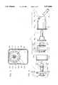
- FIG. 1is a top plan view of a reagent bottle to which the fluid delivery system of the present invention is operatively connected
- FIG. 2is a side elevational view of the reagent bottle and fluid delivery system
- FIG. 3is an end view of the reagent bottle and the fluid delivery system, looking in the direction of arrow III of FIG. 1,
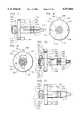
- FIG. 4is an exploded side elevational view of the coupling means and all of the individual elements of the valve assembly
- FIG. 5is vertical cross-sectional view of the coupling means and valve assembly
- FIG. 6is a vertical cross-sectional view of the valve assembly
- FIG. 7is a top plan view of the coupling means
- FIG. 8is an end view of the coupling means looking from the fight of FIG. 7,
- FIG. 9is an end view of the coupling means looking from the left of FIG. 7,
- FIG. 10is a side elevational view of the coupling means
- FIG. 11is a bottom plan view of the coupling means
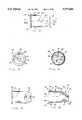
- FIG. 12is a top plan view of the housing portion of the valve assembly
- FIG. 13is an end view of the housing, looking from the left of FIG. 12,
- FIG. 14is an end view of the housing looking from the right of FIG. 12,
- FIG. 15is a bottom plan view of the housing
- FIG. 16is a vertical cross-sectional view of the housing, taken along the line XVI--XVI of FIG. 12,
- FIG. 17is an outer end view of a thrust washer which is part of the cap assembly that holds the valve assembly to the bottle,
- FIG. 18is a side elevational view of the thrust washer
- FIG. 19is an inner end view of the thrust washer
- FIG. 20is a vertical cross-sectional view of the thrust washer taken along the line XX--XX of FIG. 17 and looking in the direction of the arrows,
- FIG. 21is an outer end view of the cap portion of the cap assembly
- FIG. 22is a side elevational view of the cap
- FIG. 23is a vertical cross-sectional view of the cap
- FIG. 24is an outer end view of a first valve member and which forms part of the valve assembly
- FIG. 25is a top plan view of the first valve member
- FIG. 26is an inner end view of the first valve member
- FIG. 27is a vertical cross-sectional view of the first valve member, taken along the line XXVII--XXVII of FIG. 25 and looking in the direction of the arrows,
- FIG. 28is an outer end view of a second valve member which forms part of the valve assembly
- FIG. 29is a top plan view of the second valve member
- FIG. 30is an inner end view of the second valve member
- FIG. 31is a vertical cross-sectional view of the second valve member taken along the line XXXI--XXXI of FIG. 29 and looking in the direction of the arrows.
- FIG. 32is a front elevational view of a manifold fitting of an analytical instrument
- FIG. 33is a vertical cross-sectional view of the manifold fitting taken along the line XXXIII--XXXIII of FIG. 32 and looking in the direction of the arrows,
- FIG. 34is a vertical cross-sectional view of the coupling means operatively connected to the manifold fitting.
- FIG. 35is a top plan view of the modified valve assembly housing
- FIG. 36is a side elevational view of a modified valve assembly housing.
- valve assembly of the present inventionis generally indicated by the reference numeral 50.
- the coupling meansis generally indicated by the reference numeral 54.
- the cap assemblyis generally indicated by the reference numeral 52.
- the valve assembly 50, the coupling means 54 and the cap assembly 52are operatively connected to a reagent bottle 40 which has an interior space 42, a bottom wall 45, and a neck portion 44.
- the neck 44 of the bottle 40has a horizontal bore 48 which extends from the outer open end of the neck to the interior space 42.
- the neck 44has external threads 46 which are spaced from the opening 48.
- a tubular inwardly-extending projection or “blowdown” 49extends from the neck portion 44 into the space 42 and represents one part of locking means for the valve assembly which is described hereinafter.
- the "blowdown” 49is formed as a result of the plastic molding process and is shown somewhat exaggerated in FIG. 5.
- the bottle 40has a central longitudinal axis 47 and is designed to be supported in a generally horizontal position but at a slight angle to the horizontal as shown in FIG. 2. Also, the neck portion 44 is substantially above the central longitudinal axis 47 of the bottle.
- the cap assembly 52comprises a cap which is generally indicated by the reference numeral 104 and a thrust washer which is generally indicated by the reference numeral 106.
- the valve assembly 50comprises a housing, a first embodiment of which is generally indicated by the reference numeral 56, a first valve member which is generally indicated by the reference numeral 58, a second valve member which is generally indicated by the reference numeral 60 and a tube 61 which extends from the valve assembly 50 into the interior assembled operative positions in FIG. 6 and are shown operatively connected to the coupling means 54 in FIG. 5.
- the housing 56has a cylindrical main body portion, generally indicated by the reference numeral 69, which contains a primary bore 62 which has an air vent 68.
- the housing 56has an outer end portion, generally indicated by the reference numeral 67, which contains an outer opening 64 to the primary bore 62 and an inner end portion, generally indicated by the reference numeral 71, which contains a secondary bore 66.
- the main body portion 69tapers slightly from a relatively large diameter at the outer end portion 67 to a relatively small diameter at the inner end portion 71.
- the primary bore 62has a horizontal central longitudinal axis 59.
- the secondary bore 66extends at a downward angle from the primary bore 62 to an inner opening 73.
- the bore 62constitutes a first chamber.
- the outer opening 64constitutes a first outer opening of the first chamber.
- the second bore 66 and opening 73constitute a first inner opening of the first chamber.
- the air vent 68is located at the top of the bore 62 and constitutes a first intermediate opening of the bore or first chamber.
- a cam surface 65extends at a downward angle from the primary bore 62 to the second bore 66.
- An annular bead 72is located on the inwardly facing surface of the flange 70.
- Tab meansis located at the inner end of the housing 56.
- Tab means 74comprises a relatively stiff inner tab 76 and a deflectable resilient outer tab 78 which is slightly spaced from the tab 76.
- the housing 56is preferably made of a substantially rigid thermoplastic material. In the preferred embodiment, the housing is formed by injection molding. The material is sufficiently rigid so that the tab 76 which is relatively broad along a line which is parallel with the longitudinal axis 59 of the housing 56 is substantially non-deflectable. In contrast; the portion 78 which is relatively narrow along a line which is parallel with the central longitudinal axis 59 of the housing is substantially resiliently deflectable. The deflectable outer tab 78 extends further from the central longitudinal axis 59 of the housing than the relatively stiff inner portion 76.
- the tab 76When the housing is inserted through the opening of the bottle 40, the tab 76 passes freely within the confines of the tubular projection 49, while the resilient tab 78 is deflected by the interior surface of the projection 49 away from the inner tab and toward the axis 59.
- the tab 78returns to its normal position adjacent the tab 76. Movement of the housing toward the opening 48 of the bottle causes the tab portion 78 to engage the projection 49 and to deflect the tab 78 toward the tab 76.
- the tabs 78 and 76are slightly spaced with respect to each other, the tab 78 will be deflected a slight amount until it engages the adjacent edge surface of the tab 76.
- the tab means 74 and a tubular projection 49constitute cooperating locking means for the valve assembly 52 which enables the valve assembly to be inserted into the bottle 40 and which prevents the housing from being withdrawn from the bottle after it has been fully inserted.
- a housing to bottle joint(press or press and weld) is established to prevent torque transmitted from the cap tightening operation from rotating the housing such that downward deflection of the tube is not altered.
- FIGS. 35 and 36A second embodiment of the valve housing is illustrated in FIGS. 35 and 36 and is generally indicated by the reference numeral 56'.
- Housing 56'is identical to housing 56 except that housing 56' does not have tab means 74. The housing is pressed into the bottle neck. All features of housing 56' which are identical with features of housing 56 are identified with the same reference numeral with the addition of a prime after the numeral.
- the first valve member 58is made of an elastomeric material and comprises a relatively large diameter head potion 83 and a relatively small diameter flexible neck portion 95.
- the head portion 83contains an outer second chamber 80 which has a second outer opening 85 and an annular ridge 87 which is adjacent the opening 85.
- An annular external flange 89is located adjacent the second outer opening 85.
- the neck portion 95has an inner second chamber 82 which has a second inner opening or socket 88.
- the outer and inner second chambers 80 and 82, respectively,are separated by a penetrable wall 84.
- a slit 90is located in the wall 84 and extends from the chamber 82 to a relatively small diameter bore 93 which is connected to the chamber 80.
- the slit 90is normally closed when the valve is in a first state due to the resilient nature of the valve member 58, so that the wall 84 normally provides a seal between the chambers 80 and 82. However, the slit 90 can be physically forced through an interference fit to an open position to create an opening between the outer and inner chambers 80 and 82, respectively, when the value is in a second or functional state.
- the chamber 80is also connected to the outside of the valve member 58 by a plurality of air ducts 86 in the wall 84.
- the second valve member 60comprises an elastomeric body which has an outer surface 97 and a third chamber 92.
- the chamber 92has a third outer opening 94 and a third inner opening 96.
- An annular groove 100is located in the outer surface 97.
- An annular ridge 102extends from the inner surface 91 which defines the third chamber 92. The ridge 102 extends into the chamber 92 at a point approximately mid-way between the outer and inner openings 94 and 96, respectively.
- An annular flange 98extends around the outer periphery of the valve member 60 between the outer opening 94 and the annular groove 100.
- the second valve member 60is designed to be inserted within the outer second chamber 80 of the first valve member 58, wherein the first annular ridge 87 of the valve member 58 engages the groove 100 of the valve member 60. This ensures that the valve members 60 is properly located or seated within the chamber 80 in a predetermined position. In this predetermined position, the third inner opening 96 is closed by the wall 84. The opening 96 is horizontally aligned with the inner second chamber 82 and can be operatively connected to the chamber 82 through the hole 93 and the slit 90. However, since the slit 90 is normally closed, the chamber 80 is normally sealed from the chamber 82.
- valve member 60When the valve member 60 is inserted within the valve member 58, the flanges 98 and 89 abut as shown in FIG. 6.
- One end of the tube or straw 61is inserted into the socket 88.
- the joined valve members 60 and 58are then inserted into the first chamber or primary bore 62 of the housing 56 so that the flange 89 is located between the flanges 70 and 98 as shown in FIG. 6.
- the free end of the tube 61is inserted into the primary bore 62 and is deflected by the cam surface 65 to the secondary bore 66 and then through the secondary bore 66 so that the tube extends beyond the opening 73.
- the tube 61 and valve members 60 and 58approach their final position as shown in FIG.
- the flexible neck portion 95strikes the cam surface 65 and is deflected towards and into the bore 66 and forms a seal between the tube 61 and the housing 56 at the bore 66. Since the bore 66 extends at a downward angle from the valve assembly 50 so that when the valve assembly 50 is inserted into the bottle 40, the opposite end of the tube contacts the lower bottom most wall 45 of the bottle 40 as shown in FIG. 2. This ensures that substantially all of the reagent within the bottle will be aspirated. The angle of the opening 66 also causes the inner end of the valve member 58 to become distorted due to the elastomeric nature of the valve member 58 as shown in FIG. 6.
- the inner second chamber 82is operatively connected to the interior space 42 of the bottle through the tube 61.
- the cap assembly 52comprises a cap, generally indicated by the reference numeral 104, and a thrust washer, generally indicated by the reference numeral 106.
- the details of the thrust washer 106are shown in FIGS. 17-20.
- Details of the cap 104are shown in FIGS. 21-23.
- the cap 104has a circular side wall 108 and an outer end wall 112 which is transverse to the side wall 108.
- the inner surface of the side wall 108has internal threads 110.
- the end wall 112has a circular outer opening 114 which is horizontally aligned with a circular inner opening 116 which is defined by the inner peripheral edge 117 of the side wall 108.
- the cap 104has a central longitudinal axis 115 which extends through the center's of the openings 114 and 116.
- the thrust washer 106has a circular side wall 118 and an inner end wall 119.
- the side wall 118has an external ridge 122 and a plurality of slots 120 which create a plurality of outwardly extending segments 121.
- the outer periphery of the side wall 118defines an outer circular opening 124.
- the inner end wall 119is transverse to the side wall 118 and has an inner circular opening 126.
- a circular inwardly facing flange 128is located at the outer peripheral edge of the wall 119.
- the cap assembly 52is assembled by inserting the thrust washer 106 into the cap 104 so that the side wall 118 extends through the opening 114 of the cap.
- the outer diameter of the ridge 122is slightly greater than the diameter of the circular opening 114.
- the thrust washer 106 and the capare both constructed of a relatively rigid thermoplastic material by injection molding. However, the segments 121 of the thrust washer 106 are sufficiently resilient so as to be deflected toward the center of the opening 126 when they are forced against the peripheral edge of the opening 114.
- the ridge 122has an outwardly facing beveled surface which forces each segment 121 of the wall 118 inwardly towards the central axis of the thrust washer when the wall 118 of the thrust washer is forced against the edge of the opening 114.
- the thrust washer 106is releasably locked against movement along the axis 115 relative to the cap 104 but is free to rotate about the axis 115 relative to the cap 104.
- the fluid coupling means or coupler 54comprises a horizontal main body portion 132 which has a central longitudinal axis 127.
- a connector fittingwhich is generally indicated by the reference numeral 130 is located at the outer end of the housing and a terminal nipple 134 is located at the inner end of the housing.
- the connector fitting 130is adapted to be operatively connected to the complementary manifold fitting 55, see FIGS. 32-34, of aspirating means which forms part of an analytical instrument (not shown).
- the connector fitting 130has an outer end surface 129 which has a circular groove 131.
- An elastomeric sealing ring 133is located within the groove 131 and extends beyond the outer end surface 129.
- the connector fitting 130has a relatively wide tab 137 and a relatively narrow tab 139.
- the tabs 137 and 139are diametrically opposed and extend transversely of the longitudinal axis 127. Alternate positioning and configuration of the tabs of the connector fitting may be accomplished to engage a respective manifold fitting.
- Tab 137has an inwardly facing engaging surface 141. One end of the surface 141 has a bevel 143.
- a flange stop 145is located at the opposite end of the surface 141 and extends inwardly and transversely of the surface 141.
- the tab 139has an inwardly facing engaging surface 147. One end of the surface 147 has a bevel 149.
- An annular flange 136extends transversely from the central longitudinal horizontal axis 127 and is located adjacent and spaced from the connector fitting 130.
- a pair of fingers 144extends from the flange 136 toward the inner end of the main body portion 132.
- a longitudinal horizontal bore 138extends from an outer opening 140 at the fitting 130 through the main body portion 132 and the nipple 134 to an inner opening 142. The bore 138 functions as a liquid passageway.
- An annular groove 146is located in the outer surface of the main body portion.
- a longitudinal groove 148is located in the outer surface of the main body portion 132 and intersects the annular groove 146.
- the longitudinal groove 148functions as a gas passageway.
- the coupling means 54is operatively connected to the complementary manifold fitting 55 fixture of an analytical instrument which is capable of creating a suction at the opening 140.
- the manifold fitting 55includes a manifold cavity 150 and a front opening 152 to the cavity.
- a fluid port 156is located in an access surface 154 which forms the base of the cavity and which faces the front opening 152.
- the fluid port 156is connected to a source of sub-atmospheric pressure, which is part of the analytical instrument (not shown).
- a first projection 158 and a second projection 160extend toward each other at the opening 152.
- the projections 158 and 160are spaced from each other and define therebetween a first relatively wide slot 162 and a second relatively narrow slot 164.
- the projection 158has an inner surface 159 which is spaced from and faces the access surface 154.
- the projection 160has an inner surface 161 which is spaced from and faces the access surface 154.
- valve assembly 50After the valve assembly 50 has been assembled as shown in FIG. 6, it is inserted into the opening 48 of the bottle 40 as shown in FIG. 5.
- the valve assembly 50is applied to the bottle 40 by inserting the assembly into the bore 48 of the neck portion 44 of the bottle in a fixed predetermined position.
- the valve assemblyis inserted so that the air vent 68 of the housing 56 faces upwardly and the tube 61 extends downwardly when the bottle 40 is in a generally horizontal position as shown in FIG. 2.
- the housingis fixed to the bottle in any one of several ways. In one embodiment of the invention, the housing is fixed to the neck of the bottle, by fusing the flange 70 to the recessed annular edge 53 of the bottle, preferably by ultrasonic welding. When this procedure is used, the annular bead 72 functions as an energy director for the ultrasonic energy and is fused to the edge 53.
- valve assembly 50is fixed to the neck of the bottle by "press fitting" the housing 56 within the bore or opening 48. This is accomplished in one of two ways. A press fit is accomplished by making the outer diameter of the insertable portion of the housing slightly smaller than the diameter of the bore 48 so that the elongated beads 63 extend beyond the diameter of the bore 48. The housing 56 is then forced into the bore 48. The beads 63 distort due to the plastic composition of the housing and enable the housing to remain in the fixed predetermined position.
- the valve assemblycan also be press fitted into the bore 48 by making the outer diameter of the insertable portion of the housing slightly larger than the diameter of the bore 48.
- the inclusion of the beads 63is optional.
- the tapered configuration of the main body portion 69facilitates the press fitting of the housing 56.
- valve assemblycan also be locked in the bottle by tab means 74 as described above.
- the cap assembly 52is then screwed onto the neck 44 of the bottle. As the cap assembly is rotated, the flanges 98, 89 and 70 are squeezed together. This provides a liquid and air-tight seal between the valve assembly and the bottle at the neck 44.
- the thrust washer 106stops rotating with the cap as the cap continues to be mined in the advancing direction onto the neck 44. As a result, during the cap's torquing, the thrust washer applies only a horizontal force to the elastomeric flanges 98 and 89.
- the tube 61creates a passageway for fluid in the bottle to the inner second chamber 82, but the wall 84 prevents the fluid from passing into the chamber 80. Air within the bottle is free to enter the first chamber 62 of the housing through the air vent 68 and into the air ducts 86, but the second valve member 60 forms a seal at the openings 86 to prevent air from going beyond of the outer second chamber 80.
- a closure tab(not shown) is inserted into cap opening 114 to keep the valve assembly free of dust.
- the connector firing 130 of the coupling means 54is operatively connected to the complementary manifold fitting 55.
- the connector fitting 130is inserted into the cavity 150 of the manifold fitting 55 by aligning the tab 137 with the slot 162 and the tab 139 with the slot 164 and pushing the end surface 129 toward the access surface 154.
- the coupling means 54is then rotated clockwise to a predetermined position as viewed in FIG. 34.
- the bevels 143 and 149engage the inner surfaces 159 and 161, respectively and function as cam surfaces to guide the tabs 137 and 139 between each of the first and second projections 158 and 160, respectively, and the access surface 154.
- the bevels 143 and 149are biased against the surfaces 159 and 161, respectively, by the elastomeric sealing ring 133.
- the coupling means 54is rotated about the axis 127 for approximately 90°, at which point the flange 145 engages the adjacent edge 163 of the projection 158 to prevent further rotation.
- the longitudinal groove 148faces upwardly as shown in FIG. 34.
- Connector fitting 130 of the coupling means 54is operatively connected to the manifold fitting 55 as shown in FIG. 34.
- the opening 140 of the bore 138is axially aligned with the port 156 so that the port 156 is operatively connected to the bore or liquid passageway 138.
- the coupling means 54is operatively connected to the valve assembly by moving the bottle toward the manifold so that the coupling means extends horizontally into the third chamber 92.
- the nipple 134enters into the small diameter bore 93, thereby expanding the bore 93 and simultaneously expanding the slit 90 sufficiently to allow the nipple to penetrate the wall 84 and extend into the inner second chamber 82 as shown in FIG. 5.
- the shoulder 135 of the main body portionengages the wall 84 and forces the wall 84 away from the inner end of the second valve member 60, thereby creating a passageway between the chamber 62 and the chamber 80.
- the annular ridge 102 of the second valve memberengages the annular groove 146 of the coupling means 54 so that the coupling means is properly located within the valve assembly at a predetermined location relative to the valve assembly.
- the fingers 144engage the outer wall 112 of the cap 104 to prevent the coupling means from going beyond this predetermined position.
- the fingers 144also function as finger grips for enabling an operator to easily connect and disconnect the coupling means 54 to the manifold fitting 55.
- the inner end of the groove 148extends into the outer second chamber 80.
- the outer end of the groove 148extends beyond the cap assembly 52 to create an air or gas passageway between the chamber 80 to a point outside of the bottle cap.
- the bottleWhen the bottle is connected to the coupling means 54, it is supported on a slightly inclined supporting tray 170, which forms part of the analyzing instrument (not shown).
- the bottleis supported in a substantially horizontal position and with a slight upward tilt toward the opening of the bottle due to the inclined angle of the supporting tray.
- the bottleis filled with fluid to the extent that the fluid is just below the air vent 68 and the groove 148 so that these elements lie in the air space above the top of the bottle above the fluid.
Landscapes
- Mechanical Engineering (AREA)
- Engineering & Computer Science (AREA)
- Chemical & Material Sciences (AREA)
- Health & Medical Sciences (AREA)
- Analytical Chemistry (AREA)
- Life Sciences & Earth Sciences (AREA)
- Physics & Mathematics (AREA)
- Biochemistry (AREA)
- General Health & Medical Sciences (AREA)
- General Physics & Mathematics (AREA)
- Immunology (AREA)
- Pathology (AREA)
- Clinical Laboratory Science (AREA)
- Chemical Kinetics & Catalysis (AREA)
- Closures For Containers (AREA)
- Feeding, Discharge, Calcimining, Fusing, And Gas-Generation Devices (AREA)
- Loading And Unloading Of Fuel Tanks Or Ships (AREA)
- Infusion, Injection, And Reservoir Apparatuses (AREA)
- Jet Pumps And Other Pumps (AREA)
- Automatic Analysis And Handling Materials Therefor (AREA)
- Piezo-Electric Or Mechanical Vibrators, Or Delay Or Filter Circuits (AREA)
- Finger-Pressure Massage (AREA)
- Measurement Of Radiation (AREA)
- Sampling And Sample Adjustment (AREA)
- Devices For Dispensing Beverages (AREA)
- Centrifugal Separators (AREA)
- Reciprocating Pumps (AREA)
- Cyclones (AREA)
- Quick-Acting Or Multi-Walled Pipe Joints (AREA)
- Nozzles (AREA)
- Acyclic And Carbocyclic Compounds In Medicinal Compositions (AREA)
- Pressure Vessels And Lids Thereof (AREA)
Abstract
Description
Claims (9)
Priority Applications (1)
| Application Number | Priority Date | Filing Date | Title |
|---|---|---|---|
| US08/513,698US5573046A (en) | 1993-12-09 | 1995-08-11 | Value housing for a fluid delivery system |
Applications Claiming Priority (2)
| Application Number | Priority Date | Filing Date | Title |
|---|---|---|---|
| US08/165,137US5755269A (en) | 1993-12-09 | 1993-12-09 | Fluid delivery system |
| US08/513,698US5573046A (en) | 1993-12-09 | 1995-08-11 | Value housing for a fluid delivery system |
Related Parent Applications (1)
| Application Number | Title | Priority Date | Filing Date |
|---|---|---|---|
| US08/165,137DivisionUS5755269A (en) | 1993-12-09 | 1993-12-09 | Fluid delivery system |
Publications (1)
| Publication Number | Publication Date |
|---|---|
| US5573046Atrue US5573046A (en) | 1996-11-12 |
Family
ID=22597583
Family Applications (4)
| Application Number | Title | Priority Date | Filing Date |
|---|---|---|---|
| US08/165,137Expired - LifetimeUS5755269A (en) | 1993-12-09 | 1993-12-09 | Fluid delivery system |
| US08/513,697Expired - LifetimeUS5586590A (en) | 1993-12-09 | 1995-08-11 | Coupler for fluid delivery system |
| US08/513,699Expired - LifetimeUS5586673A (en) | 1993-12-09 | 1995-08-11 | Cap assembly for fluid delivery system |
| US08/513,698Expired - LifetimeUS5573046A (en) | 1993-12-09 | 1995-08-11 | Value housing for a fluid delivery system |
Family Applications Before (3)
| Application Number | Title | Priority Date | Filing Date |
|---|---|---|---|
| US08/165,137Expired - LifetimeUS5755269A (en) | 1993-12-09 | 1993-12-09 | Fluid delivery system |
| US08/513,697Expired - LifetimeUS5586590A (en) | 1993-12-09 | 1995-08-11 | Coupler for fluid delivery system |
| US08/513,699Expired - LifetimeUS5586673A (en) | 1993-12-09 | 1995-08-11 | Cap assembly for fluid delivery system |
Country Status (11)
| Country | Link |
|---|---|
| US (4) | US5755269A (en) |
| EP (3) | EP0829451B1 (en) |
| JP (2) | JP2858634B2 (en) |
| KR (1) | KR950017725A (en) |
| AT (3) | ATE167458T1 (en) |
| AU (1) | AU689473B2 (en) |
| CA (1) | CA2125217A1 (en) |
| DE (3) | DE69428921T2 (en) |
| DK (3) | DK0829451T3 (en) |
| ES (3) | ES2163706T3 (en) |
| PL (1) | PL306124A1 (en) |
Cited By (25)
| Publication number | Priority date | Publication date | Assignee | Title |
|---|---|---|---|---|
| US5862948A (en) | 1996-01-19 | 1999-01-26 | Sc Johnson Commerical Markets, Inc. | Docking station and bottle system |
| US6244471B1 (en)* | 1997-04-03 | 2001-06-12 | Durr Dental Gmbh & Co. Kg | Metering container |
| US20040053875A1 (en)* | 1999-01-30 | 2004-03-18 | Ribopharma Ag | Method and medicament for inhibiting the expression of a given gene |
| US20050106075A1 (en)* | 2003-11-17 | 2005-05-19 | Mutsuya Kitazawa | Fluid system coupler |
| US20080047982A1 (en)* | 2006-08-25 | 2008-02-28 | Conway Simon M | Flexible down tube and methods of use thereof |
| US7806303B1 (en)* | 2007-10-11 | 2010-10-05 | Mark Hastings | Sealable pour spout |
| US20110108447A1 (en)* | 2009-11-11 | 2011-05-12 | Rebecca Hoefing | Shrink Sleeve on Bottle With Integral Dip Tube |
| US20110108581A1 (en)* | 2009-11-11 | 2011-05-12 | Dennis Stephen R | Bottle With Integral Dip Tube |
| US8789728B2 (en)* | 2012-01-03 | 2014-07-29 | Scott Huffman | Liquid spray dispenser suction tube deflector |
| US10143350B2 (en) | 2015-09-09 | 2018-12-04 | Bissell Homecare, Inc. | Cap and receiver for coupling a container to a surface cleaning device |
| US10189614B2 (en) | 2013-03-15 | 2019-01-29 | Bissell Homecare, Inc. | Container and cap assembly |
| US11634314B1 (en) | 2022-11-17 | 2023-04-25 | Sharkninja Operating Llc | Dosing accuracy |
| US11647860B1 (en) | 2022-05-13 | 2023-05-16 | Sharkninja Operating Llc | Flavored beverage carbonation system |
| US11738988B1 (en) | 2022-11-17 | 2023-08-29 | Sharkninja Operating Llc | Ingredient container valve control |
| US11745996B1 (en) | 2022-11-17 | 2023-09-05 | Sharkninja Operating Llc | Ingredient containers for use with beverage dispensers |
| US11751585B1 (en) | 2022-05-13 | 2023-09-12 | Sharkninja Operating Llc | Flavored beverage carbonation system |
| US11871867B1 (en) | 2023-03-22 | 2024-01-16 | Sharkninja Operating Llc | Additive container with bottom cover |
| US11925287B1 (en) | 2023-03-22 | 2024-03-12 | Sharkninja Operating Llc | Additive container with inlet tube |
| US12084334B2 (en) | 2022-11-17 | 2024-09-10 | Sharkninja Operating Llc | Ingredient container |
| US12096880B2 (en) | 2022-05-13 | 2024-09-24 | Sharkninja Operating Llc | Flavorant for beverage carbonation system |
| US12103840B2 (en) | 2022-11-17 | 2024-10-01 | Sharkninja Operating Llc | Ingredient container with sealing valve |
| US12116257B1 (en) | 2023-03-22 | 2024-10-15 | Sharkninja Operating Llc | Adapter for beverage dispenser |
| US12213617B2 (en) | 2022-05-13 | 2025-02-04 | Sharkninja Operating Llc | Flavored beverage carbonation process |
| USD1091308S1 (en) | 2022-12-23 | 2025-09-02 | Sharkninja Operating Llc | Ingredient container |
| USD1092208S1 (en) | 2022-12-23 | 2025-09-09 | Sharkninja Operating Llc | Cap of ingredient container |
Families Citing this family (38)
| Publication number | Priority date | Publication date | Assignee | Title |
|---|---|---|---|---|
| US5803909A (en)* | 1994-10-06 | 1998-09-08 | Hitachi, Ltd. | Optical system for measuring metabolism in a body and imaging method |
| US5884679A (en)* | 1995-08-11 | 1999-03-23 | Bissell Inc. | Solution dispensing bottle assembly |
| US5856194A (en) | 1996-09-19 | 1999-01-05 | Abbott Laboratories | Method for determination of item of interest in a sample |
| GB9623544D0 (en)* | 1996-11-12 | 1997-01-08 | Micromass Ltd | Sample vial and vial closure device for use in gas analysis and method of using the same |
| WO1998042962A1 (en)* | 1997-03-21 | 1998-10-01 | Tamotsu Takahara | Oil drain plug for oil storage vessel and oil drain device using same |
| GB2333514B (en)* | 1998-01-21 | 2002-04-24 | Eastman Kodak Co | Mounting arrangement |
| US6184137B1 (en) | 1998-11-25 | 2001-02-06 | Applied Materials, Inc. | Structure and method for improving low temperature copper reflow in semiconductor features |
| US6142343A (en)* | 1998-12-30 | 2000-11-07 | Steris Inc | Cap and dust cover for an antiseptic soap dispenser |
| US6202717B1 (en) | 1999-08-05 | 2001-03-20 | S. C. Johnson Commercial Markets, Inc. | Dispensing bottle closure |
| US6378742B1 (en) | 2000-10-10 | 2002-04-30 | Rieke Corporation | Fluid dispensing closure |
| US6367657B1 (en)* | 2001-02-05 | 2002-04-09 | Samhongsa, Co., Ltd. | Control valve for a gas cylinder |
| EP1546021B1 (en) | 2002-08-13 | 2010-10-20 | Medical Instill Technologies, Inc. | Container and valve assembly for storing and dispensing substances, and related method |
| DE60330100D1 (en)* | 2002-09-20 | 2009-12-31 | Becton Dickinson Co | roller bottle |
| US6997219B2 (en) | 2003-05-12 | 2006-02-14 | Medical Instill Technologies, Inc. | Dispenser and apparatus and method for filling a dispenser |
| US7226231B2 (en) | 2003-07-17 | 2007-06-05 | Medical Instill Technologies, Inc. | Piston-type dispenser with one-way valve for storing and dispensing metered amounts of substances |
| EP1683566A4 (en)* | 2003-10-17 | 2008-09-24 | Fujifilm Corp | Porous film cartridge |
| US7040515B2 (en)* | 2003-11-24 | 2006-05-09 | Cactrus Drink Systems Inc. | Bottle cap |
| US7264142B2 (en) | 2004-01-27 | 2007-09-04 | Medical Instill Technologies, Inc. | Dispenser having variable-volume storage chamber and depressible one-way valve assembly for dispensing creams and other substances |
| US8789725B2 (en)* | 2004-03-29 | 2014-07-29 | P G United States Israel Ltd. | Foam dispenser nozzle |
| US20060173436A1 (en)* | 2005-01-14 | 2006-08-03 | Kimberly-Clark Worldwide, Inc. | Disposable absorbent article having a waist opening with a scalloped edge |
| US7611502B2 (en)* | 2005-10-20 | 2009-11-03 | Covidien Ag | Connector for enteral fluid delivery set |
| US7896859B2 (en)* | 2005-10-20 | 2011-03-01 | Tyco Healthcare Group Lp | Enteral feeding set |
| JP5048968B2 (en)* | 2006-05-08 | 2012-10-17 | サーパス工業株式会社 | Connector structure |
| USD582767S1 (en)* | 2006-12-07 | 2008-12-16 | Johnsondiversey, Inc. | Dispensing bottle cap |
| USD567084S1 (en) | 2006-12-07 | 2008-04-22 | Johnsondiversey, Inc. | Bottle plug |
| US20080223812A1 (en)* | 2007-03-13 | 2008-09-18 | Tomasz Domagala | Bottled Beverage Plug for Identification |
| USD578390S1 (en)* | 2007-08-23 | 2008-10-14 | Parish Orville Green | Restrictor orifice for tube products |
| KR100873915B1 (en)* | 2007-11-01 | 2008-12-12 | 주식회사 아이센스 | Solution container for blood analysis device |
| US8251346B2 (en)* | 2008-03-04 | 2012-08-28 | Infusion Innovations, Inc. | Devices, assemblies, and methods for controlling fluid flow |
| CA2717754C (en) | 2008-03-04 | 2017-06-06 | Infusion Innovations, Inc. | Devices, assemblies, and methods for controlling fluid flow |
| US20100123019A1 (en)* | 2008-11-14 | 2010-05-20 | Hydroback Hydration Systems, Llc | Bottle adaptor for personal hydration system |
| WO2010080897A1 (en)* | 2009-01-09 | 2010-07-15 | Liqui-Box Corporation | Duckbill flip cap fitment for a collapsible container |
| US9849277B2 (en) | 2010-12-15 | 2017-12-26 | Infusion Innovations, Inc. | Devices, assemblies and methods for controlling fluid flow |
| US8603047B2 (en) | 2010-12-15 | 2013-12-10 | Infusion Innovations | Devices, assemblies and methods for controlling fluid flow |
| WO2012134778A1 (en)* | 2011-03-28 | 2012-10-04 | Corning Incorporated | Container cap with kink-resistant connector |
| US20140094727A1 (en)* | 2012-09-28 | 2014-04-03 | Covidien Lp | Compression device pumping |
| EP3319682B1 (en) | 2015-07-08 | 2023-06-07 | Infusion Innovations, Inc. | Valve assembly and methods of use |
| CN109854794B (en)* | 2019-03-01 | 2021-01-19 | 中国科学院合肥物质科学研究院 | Differential pressure type quick inflation valve special for plasma fracture protection |
Citations (53)
| Publication number | Priority date | Publication date | Assignee | Title |
|---|---|---|---|---|
| US1482373A (en)* | 1922-03-16 | 1924-01-29 | James H Wallace | Stopper |
| US1679735A (en)* | 1922-03-14 | 1928-08-07 | Bassick Mfg Co | Lubricating apparatus |
| US1750512A (en)* | 1927-11-25 | 1930-03-11 | Romort Mfg Company | Liquid-spraying device |
| US1952437A (en)* | 1932-08-05 | 1934-03-27 | Ward I Huber | Dispensing device for liquid containers |
| US2149681A (en)* | 1937-01-25 | 1939-03-07 | Carey W Johnston | Control device |
| US2190054A (en)* | 1937-08-30 | 1940-02-13 | Cutter Lab | Flask and stopper therefor |
| US2526630A (en)* | 1948-06-03 | 1950-10-24 | Thomas N Bourke | Seal device for containers |
| US2598403A (en)* | 1950-07-15 | 1952-05-27 | Macey John | Dispensing bottle stopper |
| US2822054A (en)* | 1955-05-09 | 1958-02-04 | Gen Pacific Corp | Fire extinguisher |
| US2851201A (en)* | 1955-02-01 | 1958-09-09 | Edward J Poitras | Automatic vent stopper |
| US2860820A (en)* | 1953-07-30 | 1958-11-18 | Prepo Corp | Assembly and locking means for liquid handling devices |
| US2992762A (en)* | 1958-06-26 | 1961-07-18 | Forman Benjamin | Flow controlling bottle closures |
| US3067898A (en)* | 1959-05-18 | 1962-12-11 | Baxter Laboratories Inc | Parenteral solution equipment |
| US3084823A (en)* | 1959-08-13 | 1963-04-09 | Reichstein Jozef | Stoppers for vessels, especially for bottles with gaseous or sparkling liquids |
| US3157323A (en)* | 1961-04-12 | 1964-11-17 | Nat Products Co | Valve closure for bottles and the like |
| US3232485A (en)* | 1964-02-11 | 1966-02-01 | Reynolds Metals Co | Charging valve construction |
| US3233793A (en)* | 1963-09-03 | 1966-02-08 | Seaquist Valve Co | Aerosol valve |
| US3324903A (en)* | 1965-05-12 | 1967-06-13 | Hinz Karl | Syphons adapted to contain and dispense soda water |
| US3460569A (en)* | 1966-01-19 | 1969-08-12 | Aeroquip Corp | Identical halves coupling |
| US3467270A (en)* | 1967-08-03 | 1969-09-16 | Hall Robert M | Cap |
| US3499568A (en)* | 1967-12-28 | 1970-03-10 | Jose Vinas Riera | Stopper system for biological containers |
| US3512806A (en)* | 1968-01-22 | 1970-05-19 | Russell H Romney | Adapter for multiple connections to intravenous fluid receptacles and the like |
| US3904059A (en)* | 1972-02-22 | 1975-09-09 | Baxter Laboratories Inc | Sterile closure for solution bottles |
| US3923183A (en)* | 1973-03-07 | 1975-12-02 | American Hospital Supply Corp | Container for medical liquid with separable outer and inner closures |
| US4022205A (en)* | 1973-11-05 | 1977-05-10 | Tenczar Francis J | Fluid connectors |
| US4065018A (en)* | 1976-08-02 | 1977-12-27 | William J. Megowen | Closure means and method |
| FR2364827A1 (en)* | 1976-09-17 | 1978-04-14 | Grundy Teddington Ltd | COUPLING OR DISTRIBUTION HEAD FOR PRESSURE BOTTLES OR SIMILAR CONTAINERS |
| US4089444A (en)* | 1974-03-11 | 1978-05-16 | Shea Ronald E | Tapping apparatus for golden gate type beer keg openings |
| US4265363A (en)* | 1979-11-26 | 1981-05-05 | Conn J L | Container with drinking tube |
| US4265280A (en)* | 1979-01-23 | 1981-05-05 | Baxter Travenol Laboratories, Inc. | Connector member for sealed conduits |
| US4320911A (en)* | 1980-02-07 | 1982-03-23 | The United States Of America As Represented By The Administrator Of The National Aeronautics And Space Administration | High temperature penetrator assembly with bayonet plug and ramp-activated lock |
| US4433973A (en)* | 1982-01-12 | 1984-02-28 | Bioresearch Inc. | Reusable tube connector assembly |
| US4576199A (en)* | 1983-12-19 | 1986-03-18 | Svensson Jan A | Slide valve and coupling unit |
| US4611643A (en)* | 1983-11-21 | 1986-09-16 | Baxter Travenol Laboratories, Inc. | Interlocking fluid transfer device and resulting assembly |
| US4676287A (en)* | 1984-03-02 | 1987-06-30 | The Regina Company Inc. | Cartridge and docking port for a cleaning device |
| US4682704A (en)* | 1986-05-12 | 1987-07-28 | Boardman Molded Products, Inc. | Floating cap seal |
| US4715359A (en)* | 1986-03-28 | 1987-12-29 | Ryo U Yun | Safety bottle and cap for the administration of liquid radioactive iodine |
| US4740206A (en)* | 1985-03-27 | 1988-04-26 | Tobin Scandinavia Ab | Disposable pocket-size package for eye-rinsing liquid |
| EP0298376A2 (en)* | 1987-07-02 | 1989-01-11 | Baderi, Jopado | Filling and dispensing valve with drop-away valve member |
| US4854486A (en)* | 1987-05-11 | 1989-08-08 | Ciba Corning Diagnostics Corp. | Resealable container for dispensing liquid |
| US4911203A (en)* | 1988-04-26 | 1990-03-27 | Brunswick Corporation | Fuel line connector |
| US4941519A (en)* | 1988-08-19 | 1990-07-17 | American Sterilizer Company | Liquid feed system using a non-reusable container |
| US4946455A (en)* | 1988-11-25 | 1990-08-07 | Rosen Robert J | Medical tubing connector |
| US4982736A (en)* | 1989-02-08 | 1991-01-08 | Hollister Incorporated | Hermaphroditic coupling for anatomical thermal system |
| US5029624A (en)* | 1989-03-27 | 1991-07-09 | Deere & Company | Closed granular chemical handling system |
| US5031785A (en)* | 1990-02-14 | 1991-07-16 | Epicurean International Corp. | Combination vacuum/pressure pump and valve stopper for food or drink containers |
| US5038840A (en)* | 1990-07-31 | 1991-08-13 | Olin Corporation | Bubbler container automatic refill system |
| EP0477477A2 (en)* | 1990-08-06 | 1992-04-01 | Wilbur- Ellis Company | Apparatus for fluid transfer |
| US5145094A (en)* | 1990-08-20 | 1992-09-08 | Edward M. Bennett | Dispensing closure for squeeze bottle |
| EP0548570A1 (en)* | 1991-12-21 | 1993-06-30 | BURDOSA Ing. Herwig Burgert i.K. | Filling and emptying device |
| US5297599A (en)* | 1991-03-19 | 1994-03-29 | Hoffmann-Laroche Inc. | Closure device for sealing reagent containers in an automatic pipetting system |
| US5299608A (en)* | 1992-03-16 | 1994-04-05 | The Hoover Company | Sealed coupling for a fluid container |
| US5323832A (en)* | 1991-12-23 | 1994-06-28 | Ebtech, Inc. | Valve actuator for a soft drink dispenser station |
Family Cites Families (23)
| Publication number | Priority date | Publication date | Assignee | Title |
|---|---|---|---|---|
| US1250058A (en)* | 1916-12-29 | 1917-12-11 | Harry Weaver | Jar-closure. |
| US2075249A (en)* | 1935-11-23 | 1937-03-30 | Ralph W Wilson | Closure for containers |
| US2288565A (en)* | 1940-05-31 | 1942-06-30 | Mine Safety Appliances Co | Breathing apparatus supply valve |
| US2416829A (en)* | 1944-12-29 | 1947-03-04 | Parker Appliance Co | Closure cap for tube fittings |
| US3143235A (en)* | 1958-10-30 | 1964-08-04 | Lowen Stanley | Container closure |
| US3065885A (en)* | 1960-02-18 | 1962-11-27 | Anheuser Busch | Beer barrel tapping device |
| US3438553A (en)* | 1967-01-04 | 1969-04-15 | Johnston Enterprises Inc | Tapping device for beer kegs and the like |
| US3596810A (en)* | 1969-09-02 | 1971-08-03 | Perlick Co Inc The | Keg-tapping system |
| DE2212817A1 (en)* | 1972-03-16 | 1973-09-27 | Kathrein Werke Kg | Coaxial cable snap connection - with an acetal polymer or copolymer shim in a clamping sleeve |
| US4136796A (en)* | 1974-04-11 | 1979-01-30 | Greif Bros. Corporation | Vented closure |
| AU1414976A (en)* | 1975-05-21 | 1977-11-24 | Mobil Oil Australia | Drain valve |
| US4065081A (en)* | 1976-12-09 | 1977-12-27 | General Signal Corporation | Alternating current track circuits |
| US4238131A (en)* | 1978-06-12 | 1980-12-09 | Cleveland Marvin G | Flushing T for heater hose |
| FR2469641A1 (en)* | 1979-11-15 | 1981-05-22 | Gleizes Raymond | DEVICE FOR THE SEALED CONNECTION OF TWO HOLLOW CYLINDRICAL LINKS SUCH AS PIPES, FITTINGS AND THE LIKE |
| FR2526403A1 (en)* | 1982-05-10 | 1983-11-10 | Ethyl Prod | HAND-OPERATED PUMP ASSEMBLY |
| GB2211506B (en)* | 1987-10-26 | 1991-04-03 | Guest John Ltd | Improvements in or relating to tube coupling bodies |
| GB8813101D0 (en)* | 1988-06-03 | 1988-07-06 | Nicholson G P | Closure |
| US4993573A (en)* | 1989-08-14 | 1991-02-19 | Kinetek Systems, Inc. | Bottle closure |
| US5042698A (en)* | 1990-03-02 | 1991-08-27 | Eric Fessell | Easy pour spout |
| US5108524A (en)* | 1990-06-13 | 1992-04-28 | Calmar Inc. | Method of applying a manually operated dispenser to a container using a hot melt liner material |
| FR2663291A1 (en)* | 1990-06-15 | 1991-12-20 | Oreal | PROCESS FOR THE PACKAGING OF A PRODUCT IN A BOTTLE, ENSURING A BETTER STORAGE OF THE PRODUCT DURING STORAGE AND CORRESPONDING PACKAGING PACKAGE. |
| US5344053A (en)* | 1992-03-09 | 1994-09-06 | Contico International, Inc. | Trigger sprayer having a two-piece housing construction |
| US5425404A (en)* | 1993-04-20 | 1995-06-20 | Minnesota Mining And Manufacturing Company | Gravity feed fluid dispensing system |
- 1993
- 1993-12-09USUS08/165,137patent/US5755269A/ennot_activeExpired - Lifetime
- 1994
- 1994-06-06CACA002125217Apatent/CA2125217A1/ennot_activeAbandoned
- 1994-06-29AUAU66015/94Apatent/AU689473B2/ennot_activeCeased
- 1994-07-21DEDE69428921Tpatent/DE69428921T2/ennot_activeExpired - Lifetime
- 1994-07-21EPEP97203232Apatent/EP0829451B1/ennot_activeExpired - Lifetime
- 1994-07-21DKDK97203232Tpatent/DK0829451T3/enactive
- 1994-07-21ESES97203232Tpatent/ES2163706T3/ennot_activeExpired - Lifetime
- 1994-07-21EPEP94305376Apatent/EP0657382B1/ennot_activeExpired - Lifetime
- 1994-07-21ESES94305376Tpatent/ES2117213T3/ennot_activeExpired - Lifetime
- 1994-07-21ATAT94305376Tpatent/ATE167458T1/ennot_activeIP Right Cessation
- 1994-07-21ESES97203233Tpatent/ES2163707T3/ennot_activeExpired - Lifetime
- 1994-07-21DKDK94305376Tpatent/DK0657382T3/enactive
- 1994-07-21ATAT97203232Tpatent/ATE207851T1/ennot_activeIP Right Cessation
- 1994-07-21EPEP97203233Apatent/EP0825148B1/ennot_activeExpired - Lifetime
- 1994-07-21DEDE69411134Tpatent/DE69411134T2/ennot_activeExpired - Lifetime
- 1994-07-21ATAT97203233Tpatent/ATE207850T1/ennot_activeIP Right Cessation
- 1994-07-21DKDK97203233Tpatent/DK0825148T3/enactive
- 1994-07-21DEDE69428920Tpatent/DE69428920T2/ennot_activeExpired - Lifetime
- 1994-12-01JPJP6298370Apatent/JP2858634B2/ennot_activeExpired - Fee Related
- 1994-12-05PLPL94306124Apatent/PL306124A1/enunknown
- 1994-12-09KRKR1019940033849Apatent/KR950017725A/ennot_activeCeased
- 1995
- 1995-08-11USUS08/513,697patent/US5586590A/ennot_activeExpired - Lifetime
- 1995-08-11USUS08/513,699patent/US5586673A/ennot_activeExpired - Lifetime
- 1995-08-11USUS08/513,698patent/US5573046A/ennot_activeExpired - Lifetime
- 1998
- 1998-03-12JPJP10061624Apatent/JP2993636B2/ennot_activeExpired - Fee Related
Patent Citations (53)
| Publication number | Priority date | Publication date | Assignee | Title |
|---|---|---|---|---|
| US1679735A (en)* | 1922-03-14 | 1928-08-07 | Bassick Mfg Co | Lubricating apparatus |
| US1482373A (en)* | 1922-03-16 | 1924-01-29 | James H Wallace | Stopper |
| US1750512A (en)* | 1927-11-25 | 1930-03-11 | Romort Mfg Company | Liquid-spraying device |
| US1952437A (en)* | 1932-08-05 | 1934-03-27 | Ward I Huber | Dispensing device for liquid containers |
| US2149681A (en)* | 1937-01-25 | 1939-03-07 | Carey W Johnston | Control device |
| US2190054A (en)* | 1937-08-30 | 1940-02-13 | Cutter Lab | Flask and stopper therefor |
| US2526630A (en)* | 1948-06-03 | 1950-10-24 | Thomas N Bourke | Seal device for containers |
| US2598403A (en)* | 1950-07-15 | 1952-05-27 | Macey John | Dispensing bottle stopper |
| US2860820A (en)* | 1953-07-30 | 1958-11-18 | Prepo Corp | Assembly and locking means for liquid handling devices |
| US2851201A (en)* | 1955-02-01 | 1958-09-09 | Edward J Poitras | Automatic vent stopper |
| US2822054A (en)* | 1955-05-09 | 1958-02-04 | Gen Pacific Corp | Fire extinguisher |
| US2992762A (en)* | 1958-06-26 | 1961-07-18 | Forman Benjamin | Flow controlling bottle closures |
| US3067898A (en)* | 1959-05-18 | 1962-12-11 | Baxter Laboratories Inc | Parenteral solution equipment |
| US3084823A (en)* | 1959-08-13 | 1963-04-09 | Reichstein Jozef | Stoppers for vessels, especially for bottles with gaseous or sparkling liquids |
| US3157323A (en)* | 1961-04-12 | 1964-11-17 | Nat Products Co | Valve closure for bottles and the like |
| US3233793A (en)* | 1963-09-03 | 1966-02-08 | Seaquist Valve Co | Aerosol valve |
| US3232485A (en)* | 1964-02-11 | 1966-02-01 | Reynolds Metals Co | Charging valve construction |
| US3324903A (en)* | 1965-05-12 | 1967-06-13 | Hinz Karl | Syphons adapted to contain and dispense soda water |
| US3460569A (en)* | 1966-01-19 | 1969-08-12 | Aeroquip Corp | Identical halves coupling |
| US3467270A (en)* | 1967-08-03 | 1969-09-16 | Hall Robert M | Cap |
| US3499568A (en)* | 1967-12-28 | 1970-03-10 | Jose Vinas Riera | Stopper system for biological containers |
| US3512806A (en)* | 1968-01-22 | 1970-05-19 | Russell H Romney | Adapter for multiple connections to intravenous fluid receptacles and the like |
| US3904059A (en)* | 1972-02-22 | 1975-09-09 | Baxter Laboratories Inc | Sterile closure for solution bottles |
| US3923183A (en)* | 1973-03-07 | 1975-12-02 | American Hospital Supply Corp | Container for medical liquid with separable outer and inner closures |
| US4022205A (en)* | 1973-11-05 | 1977-05-10 | Tenczar Francis J | Fluid connectors |
| US4089444A (en)* | 1974-03-11 | 1978-05-16 | Shea Ronald E | Tapping apparatus for golden gate type beer keg openings |
| US4065018A (en)* | 1976-08-02 | 1977-12-27 | William J. Megowen | Closure means and method |
| FR2364827A1 (en)* | 1976-09-17 | 1978-04-14 | Grundy Teddington Ltd | COUPLING OR DISTRIBUTION HEAD FOR PRESSURE BOTTLES OR SIMILAR CONTAINERS |
| US4265280A (en)* | 1979-01-23 | 1981-05-05 | Baxter Travenol Laboratories, Inc. | Connector member for sealed conduits |
| US4265363A (en)* | 1979-11-26 | 1981-05-05 | Conn J L | Container with drinking tube |
| US4320911A (en)* | 1980-02-07 | 1982-03-23 | The United States Of America As Represented By The Administrator Of The National Aeronautics And Space Administration | High temperature penetrator assembly with bayonet plug and ramp-activated lock |
| US4433973A (en)* | 1982-01-12 | 1984-02-28 | Bioresearch Inc. | Reusable tube connector assembly |
| US4611643A (en)* | 1983-11-21 | 1986-09-16 | Baxter Travenol Laboratories, Inc. | Interlocking fluid transfer device and resulting assembly |
| US4576199A (en)* | 1983-12-19 | 1986-03-18 | Svensson Jan A | Slide valve and coupling unit |
| US4676287A (en)* | 1984-03-02 | 1987-06-30 | The Regina Company Inc. | Cartridge and docking port for a cleaning device |
| US4740206A (en)* | 1985-03-27 | 1988-04-26 | Tobin Scandinavia Ab | Disposable pocket-size package for eye-rinsing liquid |
| US4715359A (en)* | 1986-03-28 | 1987-12-29 | Ryo U Yun | Safety bottle and cap for the administration of liquid radioactive iodine |
| US4682704A (en)* | 1986-05-12 | 1987-07-28 | Boardman Molded Products, Inc. | Floating cap seal |
| US4854486A (en)* | 1987-05-11 | 1989-08-08 | Ciba Corning Diagnostics Corp. | Resealable container for dispensing liquid |
| EP0298376A2 (en)* | 1987-07-02 | 1989-01-11 | Baderi, Jopado | Filling and dispensing valve with drop-away valve member |
| US4911203A (en)* | 1988-04-26 | 1990-03-27 | Brunswick Corporation | Fuel line connector |
| US4941519A (en)* | 1988-08-19 | 1990-07-17 | American Sterilizer Company | Liquid feed system using a non-reusable container |
| US4946455A (en)* | 1988-11-25 | 1990-08-07 | Rosen Robert J | Medical tubing connector |
| US4982736A (en)* | 1989-02-08 | 1991-01-08 | Hollister Incorporated | Hermaphroditic coupling for anatomical thermal system |
| US5029624A (en)* | 1989-03-27 | 1991-07-09 | Deere & Company | Closed granular chemical handling system |
| US5031785A (en)* | 1990-02-14 | 1991-07-16 | Epicurean International Corp. | Combination vacuum/pressure pump and valve stopper for food or drink containers |
| US5038840A (en)* | 1990-07-31 | 1991-08-13 | Olin Corporation | Bubbler container automatic refill system |
| EP0477477A2 (en)* | 1990-08-06 | 1992-04-01 | Wilbur- Ellis Company | Apparatus for fluid transfer |
| US5145094A (en)* | 1990-08-20 | 1992-09-08 | Edward M. Bennett | Dispensing closure for squeeze bottle |
| US5297599A (en)* | 1991-03-19 | 1994-03-29 | Hoffmann-Laroche Inc. | Closure device for sealing reagent containers in an automatic pipetting system |
| EP0548570A1 (en)* | 1991-12-21 | 1993-06-30 | BURDOSA Ing. Herwig Burgert i.K. | Filling and emptying device |
| US5323832A (en)* | 1991-12-23 | 1994-06-28 | Ebtech, Inc. | Valve actuator for a soft drink dispenser station |
| US5299608A (en)* | 1992-03-16 | 1994-04-05 | The Hoover Company | Sealed coupling for a fluid container |
Cited By (57)
| Publication number | Priority date | Publication date | Assignee | Title |
|---|---|---|---|---|
| US5862948A (en) | 1996-01-19 | 1999-01-26 | Sc Johnson Commerical Markets, Inc. | Docking station and bottle system |
| US5954240A (en) | 1996-01-19 | 1999-09-21 | S. C. Johnson Commercial Markets, Inc. | Docking station and bottle system |
| US6244471B1 (en)* | 1997-04-03 | 2001-06-12 | Durr Dental Gmbh & Co. Kg | Metering container |
| US20080166800A1 (en)* | 1999-01-30 | 2008-07-10 | Roland Kreutzer | Method and medicament for inhibiting the expression of a given gene |
| US9902955B2 (en) | 1999-01-30 | 2018-02-27 | Alnylam Pharmaceuticals, Inc. | Method and medicament for inhibiting the expression of a given gene |
| US20080171861A1 (en)* | 1999-01-30 | 2008-07-17 | Roland Kreutzer | Method and medicament for inhibiting the expression of a given gene |
| US20080171862A1 (en)* | 1999-01-30 | 2008-07-17 | Roland Kreutzer | Method and medicament for inhibiting the expression of a given gene |
| US20080182981A1 (en)* | 1999-01-30 | 2008-07-31 | Roland Kreutzer | Method and medicament for inhibiting the expression of a given gene |
| US20080233651A1 (en)* | 1999-01-30 | 2008-09-25 | Roland Kreutzer | Method and medicament for inhibiting the expression of a given gene |
| US20080261303A1 (en)* | 1999-01-30 | 2008-10-23 | Roland Kreutzer | Method and medicament for inhibiting the expression of a given gene |
| US8183362B2 (en) | 1999-01-30 | 2012-05-22 | Alnylam Pharmaceuticals, Inc. | Method and medicament for inhibiting the expression of a given gene |
| US8114981B2 (en) | 1999-01-30 | 2012-02-14 | Alnylam Pharmaceuticals, Inc. | Method and medicament for inhibiting the expression of a given gene |
| US20040053875A1 (en)* | 1999-01-30 | 2004-03-18 | Ribopharma Ag | Method and medicament for inhibiting the expression of a given gene |
| US8114851B2 (en) | 1999-01-30 | 2012-02-14 | Alnylam Pharmaceuticals, Inc. | Method and medicament for inhibiting the expression of a given gene |
| US8101742B2 (en) | 1999-01-30 | 2012-01-24 | Alnylam Pharmaceuticals, Inc. | Method and medicament for inhibiting the expression of a given gene |
| US8729037B2 (en) | 1999-01-30 | 2014-05-20 | Alnylam Pharmaceuticals, Inc. | Method and medicament for inhibiting the expression of a given gene |
| US7431890B2 (en)* | 2003-11-17 | 2008-10-07 | Sakura Finetek U.S.A., Inc. | Fluid system coupler |
| US7837945B2 (en)* | 2003-11-17 | 2010-11-23 | Sakura Finetek U.S.A., Inc. | Fluid system coupler |
| EP1684905B1 (en)* | 2003-11-17 | 2015-04-01 | Sakura Finetek U.S.A., Inc. | Fluid system coupler |
| CN101027132B (en)* | 2003-11-17 | 2010-11-17 | 美国樱花检验仪器株式会社 | Fluid System Couplings |
| US20090004065A1 (en)* | 2003-11-17 | 2009-01-01 | Mutsuya Kitazawa | Fluid system coupler |
| WO2005050162A3 (en)* | 2003-11-17 | 2005-11-24 | Sakura Finetek Usa Inc | Fluid system coupler |
| US20050106075A1 (en)* | 2003-11-17 | 2005-05-19 | Mutsuya Kitazawa | Fluid system coupler |
| US7637397B2 (en)* | 2006-08-25 | 2009-12-29 | S.C. Johnson & Son, Inc. | Flexible down tube and methods of use thereof |
| US20080047982A1 (en)* | 2006-08-25 | 2008-02-28 | Conway Simon M | Flexible down tube and methods of use thereof |
| US7806303B1 (en)* | 2007-10-11 | 2010-10-05 | Mark Hastings | Sealable pour spout |
| US8408430B2 (en)* | 2009-11-11 | 2013-04-02 | The Clorox Company | Remote sprayer with integral dip tube |
| US8839992B2 (en) | 2009-11-11 | 2014-09-23 | The Clorox Company | Bottle with integral dip tube |
| US8297479B2 (en)* | 2009-11-11 | 2012-10-30 | The Clorox Company | Shrink sleeve on bottle with integral dip tube |
| US8608033B2 (en) | 2009-11-11 | 2013-12-17 | The Clorox Company | Process of making a shrink sleeve on a bottle with integral dip tube |
| US8627985B2 (en) | 2009-11-11 | 2014-01-14 | The Clorox Company | Bottle with integral dip tube |
| US20110121039A1 (en)* | 2009-11-11 | 2011-05-26 | Dennis Stephen R | Remote Sprayer with Integral Dip Tube |
| US20110108447A1 (en)* | 2009-11-11 | 2011-05-12 | Rebecca Hoefing | Shrink Sleeve on Bottle With Integral Dip Tube |
| US8408429B2 (en)* | 2009-11-11 | 2013-04-02 | The Clorox Company | Bottle with integral dip tube |
| US20110108581A1 (en)* | 2009-11-11 | 2011-05-12 | Dennis Stephen R | Bottle With Integral Dip Tube |
| US8789728B2 (en)* | 2012-01-03 | 2014-07-29 | Scott Huffman | Liquid spray dispenser suction tube deflector |
| US10189614B2 (en) | 2013-03-15 | 2019-01-29 | Bissell Homecare, Inc. | Container and cap assembly |
| US10647481B2 (en) | 2013-03-15 | 2020-05-12 | Bissell Inc. | Container and cap assembly |
| US10894639B2 (en) | 2013-03-15 | 2021-01-19 | Bissell Inc. | Container and cap assembly |
| US10143350B2 (en) | 2015-09-09 | 2018-12-04 | Bissell Homecare, Inc. | Cap and receiver for coupling a container to a surface cleaning device |
| US11647860B1 (en) | 2022-05-13 | 2023-05-16 | Sharkninja Operating Llc | Flavored beverage carbonation system |
| US12213617B2 (en) | 2022-05-13 | 2025-02-04 | Sharkninja Operating Llc | Flavored beverage carbonation process |
| US12096880B2 (en) | 2022-05-13 | 2024-09-24 | Sharkninja Operating Llc | Flavorant for beverage carbonation system |
| US11751585B1 (en) | 2022-05-13 | 2023-09-12 | Sharkninja Operating Llc | Flavored beverage carbonation system |
| US12103840B2 (en) | 2022-11-17 | 2024-10-01 | Sharkninja Operating Llc | Ingredient container with sealing valve |
| US12006202B1 (en) | 2022-11-17 | 2024-06-11 | Sharkninja Operating Llc | Ingredient container valve control |
| US12084334B2 (en) | 2022-11-17 | 2024-09-10 | Sharkninja Operating Llc | Ingredient container |
| US11738988B1 (en) | 2022-11-17 | 2023-08-29 | Sharkninja Operating Llc | Ingredient container valve control |
| US11745996B1 (en) | 2022-11-17 | 2023-09-05 | Sharkninja Operating Llc | Ingredient containers for use with beverage dispensers |
| US12122661B2 (en) | 2022-11-17 | 2024-10-22 | Sharkninja Operating Llc | Ingredient container valve control |
| US11634314B1 (en) | 2022-11-17 | 2023-04-25 | Sharkninja Operating Llc | Dosing accuracy |
| US12410048B2 (en) | 2022-11-17 | 2025-09-09 | Sharkninja Operating Llc | Ingredient container |
| USD1091308S1 (en) | 2022-12-23 | 2025-09-02 | Sharkninja Operating Llc | Ingredient container |
| USD1092208S1 (en) | 2022-12-23 | 2025-09-09 | Sharkninja Operating Llc | Cap of ingredient container |
| US11871867B1 (en) | 2023-03-22 | 2024-01-16 | Sharkninja Operating Llc | Additive container with bottom cover |
| US11925287B1 (en) | 2023-03-22 | 2024-03-12 | Sharkninja Operating Llc | Additive container with inlet tube |
| US12116257B1 (en) | 2023-03-22 | 2024-10-15 | Sharkninja Operating Llc | Adapter for beverage dispenser |
Also Published As
| Publication number | Publication date |
|---|---|
| EP0657382A3 (en) | 1995-07-19 |
| DK0829451T3 (en) | 2002-01-21 |
| EP0825148A2 (en) | 1998-02-25 |
| US5755269A (en) | 1998-05-26 |
| EP0825148A3 (en) | 1998-03-11 |
| DK0657382T3 (en) | 1999-04-06 |
| ES2163707T3 (en) | 2002-02-01 |
| DE69428920D1 (en) | 2001-12-06 |
| EP0657382B1 (en) | 1998-06-17 |
| DE69428921D1 (en) | 2001-12-06 |
| CA2125217A1 (en) | 1995-06-10 |
| JP2993636B2 (en) | 1999-12-20 |
| JP2858634B2 (en) | 1999-02-17 |
| DE69411134D1 (en) | 1998-07-23 |
| ES2117213T3 (en) | 1998-08-01 |
| AU6601594A (en) | 1995-06-15 |
| AU689473B2 (en) | 1998-04-02 |
| ATE207850T1 (en) | 2001-11-15 |
| US5586590A (en) | 1996-12-24 |
| PL306124A1 (en) | 1995-06-12 |
| JPH10318887A (en) | 1998-12-04 |
| EP0825148B1 (en) | 2001-10-31 |
| JPH0852343A (en) | 1996-02-27 |
| US5586673A (en) | 1996-12-24 |
| DE69428920T2 (en) | 2002-04-11 |
| EP0829451B1 (en) | 2001-10-31 |
| DE69428921T2 (en) | 2002-04-11 |
| DE69411134T2 (en) | 1998-10-22 |
| EP0657382A2 (en) | 1995-06-14 |
| ATE207851T1 (en) | 2001-11-15 |
| ATE167458T1 (en) | 1998-07-15 |
| DK0825148T3 (en) | 2002-02-18 |
| EP0829451A1 (en) | 1998-03-18 |
| KR950017725A (en) | 1995-07-20 |
| ES2163706T3 (en) | 2002-02-01 |
Similar Documents
| Publication | Publication Date | Title |
|---|---|---|
| US5573046A (en) | Value housing for a fluid delivery system | |
| AU2004200893B9 (en) | Transfer Device, in Particular for Medical Fluids | |
| US20200038289A1 (en) | Connection equipment and equipment connector | |
| US4798605A (en) | Device for connecting and draining a pouch | |
| JP3512718B2 (en) | Pipe fittings | |
| EP1011786B1 (en) | Aseptic connection device | |
| US5569235A (en) | Valve and valved container for use with a syringe fitting | |
| US6481571B1 (en) | Dual-component container system | |
| CZ103993A3 (en) | Elastomeric plug for a liquid-containing container | |
| MXPA06013911A (en) | Connector . | |
| US3945603A (en) | Valve particularly adapted for use in vacuum work | |
| EP4490063A1 (en) | Dispensing system | |
| JPS58160690A (en) | Connector for connecting fluid | |
| EP1185480B1 (en) | Coupling | |
| EP0345071A1 (en) | Improvements relating to couplings for the dispensing of fluids from containers | |
| GB2101275A (en) | Tap for drinks container | |
| TWI734281B (en) | Connector | |
| JP2021020739A (en) | Hermetically sealed thermoplastic container | |
| KR100310629B1 (en) | Rib Pipe Connecting Member | |
| WO2021149819A1 (en) | Transfer needle | |
| KR20000077246A (en) | Resin pipe connecting joint of fluid machinery and tools having quartz made housing | |
| JPH1053297A (en) | Connector joint for drink container |
Legal Events
| Date | Code | Title | Description |
|---|---|---|---|
| STCF | Information on status: patent grant | Free format text:PATENTED CASE | |
| FEPP | Fee payment procedure | Free format text:PAYOR NUMBER ASSIGNED (ORIGINAL EVENT CODE: ASPN); ENTITY STATUS OF PATENT OWNER: LARGE ENTITY | |
| FPAY | Fee payment | Year of fee payment:4 | |
| FPAY | Fee payment | Year of fee payment:8 | |
| FPAY | Fee payment | Year of fee payment:12 | |
| AS | Assignment | Owner name:CIBA CORNING DIAGNOSTICS CORP.,MASSACHUSETTS Free format text:ASSIGNMENT OF ASSIGNORS INTEREST;ASSIGNORS:VENOOKER, RONALD J.;SCAVITTO, JOHN A.;KARKANTIS, PETER N.;AND OTHERS;REEL/FRAME:024358/0565 Effective date:19940125 | |
| AS | Assignment | Owner name:CHIRON DIAGNOSTICS CORPORATION,MASSACHUSETTS Free format text:CHANGE OF NAME;ASSIGNOR:CIBA CORNING DIAGNOSTICS CORP.;REEL/FRAME:024463/0443 Effective date:19961007 | |
| AS | Assignment | Owner name:BAYER CORPORATION,PENNSYLVANIA Free format text:MERGER;ASSIGNOR:CHIRON DIAGNOSTICS CORPORATION;REEL/FRAME:024468/0567 Effective date:19990305 | |
| AS | Assignment | Owner name:SIEMENS HEALTHCARE DIAGNOSTICS INC.,NEW YORK Free format text:ASSIGNMENT OF ASSIGNORS INTEREST;ASSIGNOR:BAYER CORPORATION;REEL/FRAME:024474/0810 Effective date:20070101 |