US5573007A - Gas column pressure monitoring catheters - Google Patents
Gas column pressure monitoring cathetersDownload PDFInfo
- Publication number
- US5573007A US5573007AUS08/287,195US28719594AUS5573007AUS 5573007 AUS5573007 AUS 5573007AUS 28719594 AUS28719594 AUS 28719594AUS 5573007 AUS5573007 AUS 5573007A
- Authority
- US
- United States
- Prior art keywords
- catheter
- gas
- membrane
- lumen
- pressure
- Prior art date
- Legal status (The legal status is an assumption and is not a legal conclusion. Google has not performed a legal analysis and makes no representation as to the accuracy of the status listed.)
- Expired - Lifetime
Links
Images


Classifications
- A—HUMAN NECESSITIES
- A61—MEDICAL OR VETERINARY SCIENCE; HYGIENE
- A61B—DIAGNOSIS; SURGERY; IDENTIFICATION
- A61B5/00—Measuring for diagnostic purposes; Identification of persons
- A61B5/03—Measuring fluid pressure within the body other than blood pressure, e.g. cerebral pressure ; Measuring pressure in body tissues or organs
- A61B5/031—Intracranial pressure
- A—HUMAN NECESSITIES
- A61—MEDICAL OR VETERINARY SCIENCE; HYGIENE
- A61B—DIAGNOSIS; SURGERY; IDENTIFICATION
- A61B5/00—Measuring for diagnostic purposes; Identification of persons
- A61B5/02—Detecting, measuring or recording for evaluating the cardiovascular system, e.g. pulse, heart rate, blood pressure or blood flow
- A61B5/021—Measuring pressure in heart or blood vessels
- A61B5/0215—Measuring pressure in heart or blood vessels by means inserted into the body
- A—HUMAN NECESSITIES
- A61—MEDICAL OR VETERINARY SCIENCE; HYGIENE
- A61B—DIAGNOSIS; SURGERY; IDENTIFICATION
- A61B5/00—Measuring for diagnostic purposes; Identification of persons
- A61B5/03—Measuring fluid pressure within the body other than blood pressure, e.g. cerebral pressure ; Measuring pressure in body tissues or organs
- A61B5/033—Uterine pressure
- A61B5/035—Intra-uterine probes therefor
- A—HUMAN NECESSITIES
- A61—MEDICAL OR VETERINARY SCIENCE; HYGIENE
- A61M—DEVICES FOR INTRODUCING MEDIA INTO, OR ONTO, THE BODY; DEVICES FOR TRANSDUCING BODY MEDIA OR FOR TAKING MEDIA FROM THE BODY; DEVICES FOR PRODUCING OR ENDING SLEEP OR STUPOR
- A61M25/00—Catheters; Hollow probes
- A61M2025/0001—Catheters; Hollow probes for pressure measurement
- A61M2025/0003—Catheters; Hollow probes for pressure measurement having an additional lumen transmitting fluid pressure to the outside for measurement
Definitions
- the present inventionpertains generally to medical equipment and more particularly to air filled catheter systems for monitoring pressures within blood vessels and other anatomical passageways/cavities of a mammalian body.
- Liquid filled pressure monitoring catheters of the above-described typehave been used to monitor various pressures within the mammalian body, including arterial pressure, central venous pressure, pulmonary artery pressures, pressures within the chambers of the heart, intracranial pressure, intrauterine pressure during labor & delivery etc...
- WO86/03957(Speigelberg) describes a medical pressure monitoring catheter having a gas-filled lumen extending longitudinally therethrough and in gaseous communication with the inflation space of a partially inflated bag. Changes in pressure against the outer surface of the bag are transmitted through the gas-filled lumen of the catheter to an externally located pressure sensor.
- An electromechanical pump systemis utilized to provide the desired degree of bag inflation to facilitate the intended pressure monitoring function of the catheter.
- the present inventionis a gas-column pressure measuring catheter which is insertable into a mammalian body, and usable to transmit pressure changes from a location within the mammalian body to a pressure sensor which is either incorporated into, or connectable to, the catheter.
- the cathetercomprises an elongate flexible catheter body having a gas filled lumen extending longitudinally through at least a portion of said catheter body. At least one gas-filled membrane-walled chamber is formed on the catheter body, in fluidic communication with said gas filled lumen. Such gas-filled chamber is at least partially defined or bounded by a flaccid membrane 24, 40.
- Such membrane 24, 40is positioned and configured such that pressure exerted against the outer surface of the membrane 24, 40 will cause the membrane 24, 40 to compress or move inwardly, thereby increasing the pressure of the gas within the gas-filled chamber and associated catheter lumen. A subsequent decrease in the pressure exerted against the outer surface of the membrane 24, 40 will allow the membrane 24, 40 to decompress or move outwardly, thereby lowering the pressure of the gas within the chamber and lumen.
- the catheter lumenis connectable to, or may incorporate, a pressure sensor which is operative to sense the changes in gas pressure within the catheter lumen.
- the pressure sensoremits electrical signals in response to such changes in gas pressure within the catheter lumen indicative of the magnitude of pressure changes against the outer surface of the flaccid wall or membrane 24, 40.
- the pressure sensormay be connectable to a monitor or other pressure displaying or recording apparatus to permit monitoring or recordation of the sensed pressure changes.
- the flaccid membrane 24, 40which defines or bounds at least a portion of the gas filled chamber may be in the form of a bulbous flaccid membrane 24 mounted on the distal end of the catheter body.
- the flaccid membrane 40may be of an annular, cylindrical or other configuration and mounted on the sidewall of the catheter body at some location between the proximal and distal ends thereof.
- the gas column pressure measuring catheters of the present inventionmay incorporate one or more working lumens, separate and apart from the gas-filled pressure monitoring lumen(s), which extend longitudinally through the catheter body and terminate in one or more infusion/withdrawal apertures, to permit infusion and/or withdrawal of liquids or other substances through the catheter.
- the gas-column pressure monitoring catheters of the present inventionmay be specifically configured and equipped for specific pressure monitoring applications.
- the catheter of the present inventionmay be specifically configured as a right-heart pulmonary artery catheter (e g., "Swan-Ganz" catheter)
- the cathetermay comprise an elongate flexible catheter body having at least a first gas-filled pulmonary artery pressure monitoring lumen which extends longitudinally through the catheter body and terminates in a gas-filled membrane-walled pulmonary artery pressure monitoring chamber at the distal end of the catheter body.
- a pulmonary artery occlusion or wedge balloonis positioned near the distal tip of the catheter and, when inflated, will occlude blood flow through the pulmonary artery in which the catheter is located, thereby facilitating a measurement of pulmonary artery wedge pressure by the gas-filled membrane-walled pressure sensing chamber on the distal end of the catheter body.
- a thermistor systemmay be incorporated within the body of the catheter to facilitate the measurement of cardiac output by known thermal dilution methodology.
- an optional thermal dilution injectate lumenmay extend from the proximal end of the catheter body to an injectate port located on the portion of the catheter body which resides in the vena cava or right atrium of the heart to facilitate injection of a desired thermal dilution injectate for accomplishing cardiac output measurement.
- an optional blood sample withdrawal lumenmay extend through the catheter body, terminating in a blood withdrawal port near the distal end thereof, to facilitate withdrawal of mixed venous blood samples from the pulmonary artery.
- an optional second gas-filled lumenmay extend from the proximal end of the catheter body to a second gas-filled membrane-walled pressure monitoring chamber located on the catheter body at a location which will reside in the vena cava thereby facilitating the monitoring of central venous pressure.
- a gas-column pressure monitoring catheter of the present inventionmay be specifically constructed and configured for use as an intracranial pressure monitoring catheter.
- the devicewill comprise an elongate flexible catheter body having at least one gas-filled lumen extending longitudinally therethrough in communication with at least one gas-filled, membrane-wall pressure monitoring chamber of the foregoing character, positioned at or near the distal end of the catheter body.
- An optional blind stylet-receiving lumenmay extend distally through the catheter body, from a stylet entry aperture located a spaced distance from the distal end of the catheter body, to a blind end point located near or substantially coterminous with the distal end of the catheter body.
- a stiffening styletsuch as a wire, is insertable through the stylet entry aperture, and advanceable into the stylet lumen to a point where the distal end of the stylet abuts against the blind endpoint of the stylet lumen.
- the styletwill serve to stiffen only a distal portion of the catheter body, and will facilitate intracranial insertion of the catheter by way of a known scalp tunnel technique.
- the intracranial pressure monitoring embodiment of the cathetermay comprise one or more hollow lumens extending throughout he catheter body for venting or allowing outflow of excess cerebral spinal fluid, thereby preventing the buildup of excessive intracranial pressure.
- a gas-column pressure monitoring catheter of the present inventionmay be specifically configured and constructed for use as a central venous pressure monitoring catheter.
- the cathetermay comprise an elongate flexible catheter body having a gas-filled central venous pressure monitoring lumen extending longitudinally through the catheter body and communicating with a gas-filled membrane-walled pressure monitoring chamber.
- the gas-filled membrane-walled pressure monitoring chambermay be located on the distal tip of the catheter body, or may be located on the side wall of the catheter body.
- One or more separate working lumen(s), for infusion of fluids and/or withdrawal of blood samples,extends through the catheter body and terminates in at least one infusion/withdrawal aperture located at or near the distal end of the catheter body.
- the cathetermay be inserted and advanced to a point where the membrane-walled chamber is located in the vena cava or other locations suitable for monitoring of central venous pressure. While the catheter remains in such position, the working lumen(s) may be periodically or continuously utilized to infuse fluids and/or withdraw blood samples from the central venous circulation.
- a gas column pressure monitoring catheter of the present inventionmay be specifically configured and constructed for use as an intrauterine pressure monitoring catheter.
- the devicewill comprise an elongate flexible catheter body having one or more gas-filled lumens extending longitudinally therethrough in communication with one or more gas-filled membrane-wall pressure monitoring chambers of the types described hereabove.
- the provision of two or more gas-filled membrane-wall pressure monitoring chamber on the catheter bodywill permit the catheter to consistently monitor changes in intrauterine pressure, without require frequent repositioning of the catheter due to regionalized depletion or drainage of amniotic fluid.
- a moisture absorbing material or apparatusmay be incorporated into, or utilized in connection with, the gas-filled pressure monitoring catheter to remove or absorb and hold any moisture which accumulates within the gas-filled pressure monitoring lumen of the catheter.
- such moisture absorbing material or apparatusmay comprise a hygroscopic material disposed within, or coated upon the walls of at least that portion of the gas-filled pressure monitoring lumen where the catheter transitions from body temperatures to room temperature.
- wicking thread or other absorbable strandmay be positioned within the gas-filled pressure monitoring lumen, so as to continually absorb condensate and prevent such condensate from forming a liquid plug within the gas-filled pressure monitoring lumen.
- a condensation inhibiting elementmay be utilized to prevent condensation of water vapor within the exteriorized proximal portion of the catheter due to the inherent lower temperature of the exteriorized proximal portion, relative to the intracorporeally inserted distal portion thereof.
- a heating apparatusmay be incorporated into or applied to the proximal portion of the catheter for warming the proximal portion of the catheter to a temperature which is close enough to the temperature of the intracorporeally inserted distal portion of the catheter to prevent condensation of any water vapor which accumulates within the gas-filled lumen of the catheter during use.
- apparatus and systems for passing make-up gas into the catheter lumen to replenish gas which is lost from the catheter during useare provided.
- One manner in which gas may be lost from the catheter during useis through outward diffusion of gas through the flaccid membrane 24, 40 while the catheter remains indwelling within the mammalian body.
- a pressurizing apparatussuch as a pump or diffusive gas infusing device may be connected to the catheter for purposes of providing a flow of make-up gas into the catheter lumen.
- the preferred diffusive make-up gas system of the present inventionprovides a diffusive flow of makeup gas at a rate which is substantially equal to the rate at which gas will diffuse outwardly through the flaccid membrane of the catheter, thereby maintaining the desired volume of gas within the catheter for an extended period of time.
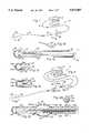
- FIG. 1is a perspective view of a first embodiment of a gas-column pressure monitoring catheter system of the present invention.
- FIG. 1ais a partial longitudinal sectional view of the distal-most portion of the catheter shown in FIG. 1.
- FIG. 1bis a perspective view of the proximal end of the catheter shown in FIG. 1.
- FIG. 1cis a longitudinal sectional view of an alternative distal tip configuration showing an alternative construction of the gas-filled membrane-walled pressure monitoring chamber at the distal end of the catheter of FIG. 1.
- FIG. 1dis a longitudinal sectional view of another alternative distal tip configuration having an alternative bellows-membrane walled pressure monitor chamber.
- FIG. 2is a perspective view of a second embodiment of a pressure monitoring catheter system of the present invention incorporating two (2) gas-filled lumens and two (2) gas-filled diaphragmatic pressure measuring chambers.
- FIG. 2ais a longitudinal section view of the distal-most portion of the catheter of FIG. 2.
- FIG. 2bis a cross sectional view through line 2b--2b of FIG. 2.
- FIG. 3is a perspective view of a third embodiment of a pressure monitoring catheter system of the present invention incorporating a separate liquidinfusion/aspiration lumen extending through the catheter body.
- FIG. 3ais a longitudinal sectional view of the distal-most portion of the catheter of FIG. 3.
- FIG. 3bis a cross sectional view through line 3b--3b of FIG. 3a.
- FIG. 3cis a longitudinal sectional view of an alternative configuration of the distal-most portion of the catheter of FIG. 3.
- FIG. 3dis a cross-sectional view through line 3d--3d of FIG. 3c.
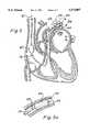
- FIG. 4is a perspective view of a fourth embodiment of a perspective view of a fourth embodiment of a pressure monitoring catheter system of the present invention intended for insertion into a pulmonary artery, and incorporating multiple gas-filled lumens, multiple gas-filled membrane-walled pressure measuring chambers, a pulmonary artery occlusion balloon, a cardiac output measuring thermistor system and a sample withdrawal lumen for obtaining mixed venous blood samples from the pulmonary artery.
- FIG. 4ais a longitudinal sectional view of a distal portion of the catheter of FIG. 4 which resides within a pulmonary artery during operative placement of the catheter.
- FIG. 4bis a longitudinal section view of a central portion of the catheter of FIG. 4 intended to reside within the vena cava during operative placement of the catheter.
- FIG. 4cis a cross sectional view through line 4d--4d of FIG. 4a.
- FIG. 4dis a cross sectional view through line 4e--4e of FIG. 4b.
- FIG. 5is a partial cut-away perspective view of a human heart and thoracic blood vessels having the pulmonary artery catheter of FIG. 4 operatively positioned therein.
- FIG. 5ais an enlarged view of region 5a of FIG. 5.
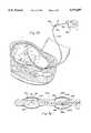
- FIGS. 6 and 6aare perspective view of a fifth embodiment of a gas-filled pressure monitoring catheter system of the present invention usable for intracranial pressure monitoring.
- FIG. 6bis a perspective view of the distal-most portion of the catheter of FIG. 6a having a removable stiffening stylet member positioned therein.
- FIG. 6dis a cutaway view of the human cranium having the catheter of FIG. 6a operatively inserted into a ventricle of the brain by way of a scalp-tunnel insertion technique
- FIGS. 7a and 7bare perspective view of a sixth embodiment of a gas-filled pressure monitor catheter system of the present invention intended for monitoring of intrauterine pressures.
- FIG. 7ais a longitudinal sectional view of the distal-most portion of the catheter.
- FIG. 8is an exploded, partially sectional view of two (2) separate components which comprise a preferred pressure maintenance/pressure sensor coupling system for a) coupling the gas-filled lumen(s) of the catheter to an extracorporeally located pressure sensor and b) maintaining a desired gas pressure within the catheter lumen(s) and membrane-walled pressure monitoring chamber(s) for an extended period of time despite any diffusive loss of gas therefrom.
- a preferred pressure maintenance/pressure sensor coupling systemfor a) coupling the gas-filled lumen(s) of the catheter to an extracorporeally located pressure sensor and b) maintaining a desired gas pressure within the catheter lumen(s) and membrane-walled pressure monitoring chamber(s) for an extended period of time despite any diffusive loss of gas therefrom.
- FIG. 8ais a non-exploded view of the components of FIG. 8, operatively coupled to one another.
- all embodiments of the inventionmay be constructed in various ways, including as the specific embodiments described herebelow, all embodiments of the invention do share certain basic attributes.
- all embodiments of the inventioncomprise an elongate (i.e., having a length greater than its width) catheter 12 having at least one gas-filled pressure monitoring lumen 22 extending longitudinally through at least a portion thereof.
- a gas-filled membrane-walled chamber 30, 48is formed on the outer surface of the catheter 12, in gaseous communication with the gas-filled pressure monitoring lumen 22.
- a pressure sensor 14is connected to the proximal end of the gas-filled pressure monitoring lumen 22 to sense and display or record the changes in pressure which are communicated through the gas-filled pressure monitoring lumen 22 of the catheter 12.
- a pressure sensormay be mounted or incorporated into the catheter 12, or proximal connector 38 formed on the proximal end of the catheter 12. In such embodiments where a pressure sensor is actually incorporated into the catheter 12 or proximal connector 38 thereon the external pressure sensor 14 will not be required and the proximal end of the catheter 38 will be connected to the monitor 18 by way of a standard wiring or electrical connection of the type known in the art.
- the gas-filled membrane-walled chamber 30, 48 of the catheter 12has a flaccid membrane 24, 40 disposed thereon such that pressure exerted against the outer surface of the membrane 24, 40 causes the membrane to move or translate inwardly, thereby compressing the gas within the gas-filled chamber 30, 48 and lumen 22 of the catheter 12.
- the membraneWhen the pressure against the outer surface of the membrane 24, 40 is decreased, the membrane will move or translate outwardly, thereby lowering the pressure of gas within the chamber 30, 48 and lumen 22 of the catheter 12.
- the volume of gas within the lumen 22, relative to that within the chamber 30, 48is sized to facilitate the desired pressure range of the pressure monitoring catheter 12.
- the lumen diameteris selected relative the lumen length to achieve the desired frequency response.
- the flaccid membrane which forms a wall or portion of the membrane-walled chamber 30, 48is preferably formed of one or more polymeric materials in a thin film form which exhibit the desired pliability, with minimal gas or liquid permeability so as to minimize outward migration of gas from the catheter 12 and/or inward migration of water vapor or other matter from any body fluid coming into contact with the outer surface of the membrane 24, 40.
- polymeric materials which may be utilized alone, or in combination, for formation of the membrane 24, 40include polyurethane, polyvinyl cloride (PVC) and polyvinylidene (e.g., Saran).
- water vapormay migrate from the surrounding body fluid, into the gas-filled membrane-walled chamber 30, 48 of the catheter 12.
- Such water vapormay condense in the exteriorized proximal portion of the catheter 12 if such exteriorized proximal portion of the catheter 12 is at a lower temperature than the intracorporeally inserted distal portion thereof.
- condensation of liquid within the gas-filled pressure monitoring lumen 22may interfere with the desired communication of pressure changes through the lumen 22.
- the inertial effects of moisture accumulating within the pressure-monitoring lumen 22may affect the frequency response of the system.
- a hygroscopic materialmay be disposed within the gas-filled pressure monitoring lumen 22, or coated on the inner walls thereof as indicated at 23 in FIG. 1A, to take up and hold any moisture which forms in the lumen 22 during use of the catheter 12
- Polyacrylamideis a suitable hygroscopic material for this purpose.
- Polyacrylamide beadsmay be adhered to the luminal surface of the pressure monitoring lumen 22 by way of an adhesive.
- a polyacrylamide coatingmay be formed on the lumenal surface of the gas-filled pressure monitoring lumen 22.
- Alternative materials and/or methods for preventing the formation of, or removing, condensation moisture from the pressure monitoring lumen 22include a wicking thread or capillary member disposed within the lumen.
- an electrical resistance heater or other heating elementmay be formed within or applied to the exteriorized proximal portion of the catheter body so as to maintain such exteriorized portion of the catheter 12 at the same temperature as the intracorporeally inserted distal portion thereof. Such warming of the proximal portion of the catheter body will avoid the temperature differential between the intracorporeally inserted and exteriorized portions of the catheter and may avoid the formation of condensation moisture within the proximal portion of the catheter body.
- the membranous wall of the gas-filled membrane-walled pressure monitoring chamber 30, 48may be formed of any suitable material flexible enough to give accurate pressure readings through the catheter 12.
- One presently preferred materialis polyurethane film.
- Other polymeric film materialsmay also be usable.
- the propensity for outward migration of gas from the gas-filled chamber 30, 48, and the corresponding propensity for inward migration of water vapor from the surrounding body fluids,will depend on the permeability of the material of which the membranous wall of the membrane-walled chamber 30, 48 is formed.
- a basic pressure monitoring catheter system 10 of the present inventioncomprises an elongate flexible air column catheter 12 which is connectable to a pressure sensor apparatus 14.
- a cable 16connects the pressure sensor apparatus 14 to a monitor 18 on which an indication of the sensed pressure is displayed,
- the catheter 12 of the system 10comprises an elongate pliable catheter body 20 having an outer surface 36 and a hollow lumen 22 extending longitudinally therethrough.
- the catheter lumen 22has an inner diameter D 1 .
- the outer surface 36 of the catheter body 20has an outer diameter D 2 .
- a bulbous pressure sensing membrane 24is mounted on the distal end of the catheter body 20.
- the bulbous membrane 24is preferably formed of a polymeric film such as polyurethane, polyvinyl chloride (PVC), and/or polyvinylidene (Saran) and has a preferred thickness of approximately 0.5-1.5 mm.
- the bulbous membrane 24 on the distal end of the catheter body 20has an outer surface 26 and an inner surface 28.
- the inner surface 28 of the bulbous membrane 24defines the distal boundary or wall of a gas-filled chamber 30 adjacent the distal end of the catheter body 20.
- the distal gas-filled membrane-walled chamber 30is in fluidic communication with the catheter lumen 22.
- the bulbous membrane 24will flex or move in response to changes in pressure against the outer surface 26 of the membrane 24. Such flexing or movement of the distal membrane 24 will result in corresponding compression or decompression of the gas within distal chamber 30 and lumen 22 of the catheter 12, thereby communicating such changes in pressure to the pressure sensor 14 and monitor 18.
- the bulbous distal membrane 24 and gas-filled membrane-walled distal chamber 30may be manufactured in various different ways, with various different configurational attributes.
- a small region at the distal end of the catheter body 20is turned down or cut in so as to provide a reduced-diameter shoulder upon which the membrane 24 may be affixed.
- the bulbous distal membrane 24may be preferably sized and configured such that, when in its distended operative configuration, the outer diameter of the bulbous membrane 24 is substantially the same as, or only slightly larger than, the adjacent outer diameter D 2 of the distal end of the catheter body 20. Also, the bulbous distal membrane 24, when in its distended operative configuration, will prefereably extend distally beyond the distal end of the catheter body 12 by a distance no more than eight (8) times the diameter of the distal end of the catheter body 12.
- the volume of the gas-filled distal chamber 30may be enhanced by forming a hollow region 32 within the distal end of the catheter body 20 such that the internal volume of the chamber 30 will be made up of the volume of space defined by the inner surface 28a of the diaphragm 24a in combination with the volume of the hollow region 32 within the distal end of the catheter body 20.
- a bellows type membrane cap 24bis affixed to the distal end of the catheter body 20.
- Such bellows-type membrane cap 24bhas a series of pleats of folds 34 which will flex back and forth in response to changes in pressure on the outer surface thereof.
- any changes in the pressure exerted against the outer surface 26 of the bulbous distal membrane 24will cause the bulbous distal membrane 24 to flex or translate inwardly, thereby compressing the gas contained within the distal chamber 30 and lumen 22 of the catheter.
- a proximal connector 38 on the proximal end of the catheter lumen 22is coupleable to a pressure sensor 14 to enable the pressure sensor 14 to receive and sense changes in pressure within the catheter lumen 22.
- the proximal connector 38has an inner bore 39 which is substantially the same size as the gas-filled lumen of the catheter so as not to create an expansion chamber which would adversely affect frequency response. Insertion of the proximal connector 38 into the bore of the sensor 14 to a stopping point therein entraps a defined volume of the gaseous medium within the lumen 22 and distal chamber 30 of the catheter 12.
- proximal connector 38 and corresponding bore of the sensor 14be specifically sized and configured such that the act of inserting the proximal connector 38 into the sensor 14 to its intended stopping point will entrap the desired volume of gas within the lumen 22 and distal chamber 30 of the catheter 12. Such preferred volume of gaseous medium within the catheter 12 will cause the distal membrane 24 to approach its fully distended configuration when the outer surface 26 of the distal membrane 24 is surrounded by ambient room air pressure.
- the distal membrane 24will assume a less than a fully distended configuration wherefrom it will be capable of translating both inwardly and outwardly in response to respective increases and decreases in pressure in the surrounding anatomical passageway or cavity of the mammalian body.
- the gas column pressure monitoring catheter 10may be configured such that the hollow gas filled lumen 22 of the catheter 12 extends through the catheter body and terminates in an aperture 43 located on the side wall of the catheter body, some distance proximal to the distal end thereof.
- the membrane 40defines the outer wall of a gas-filled chamber 48 in fluidic communication with the lumen 22 of the catheter through aperture 43.
- the gas-filled membrane-walled pressure monitoring chamber 48 located on the side wall of the catheter bodyserves to communicate changes in pressure to the externally located pressure sensor 14 in the same general manner as that described hereabove for the bulbous distal tip gas-filled membrane walled pressure sensing chamber 30.
- Examples of embodiments of the catheter 12 which incorporate a gas-filled membrane-walled side wall pressure sensing chamber 48include those shown in FIGS. 2, 2a, 3c, 4-4f, 5-5a and 7a-7b.
- FIGS. 2-2bshow an alternative embodiment of a catheter system 10a of the invention, wherein the catheter 12a comprises a dual lumen catheter 12b having two separate gas-filled membrane-walled pressure sensing chambers 30, 40, located on the distal tip and sidewall of the catheter 12, respectively, for simultaneous and/or separate monitoring of pressures at such separate locations on the catheter body.
- the catheter 12bincorporates a first lumen 22a extending longitudinally through the catheter body to an air filled distal chamber 30 having a bulbous distal tip membrane 24 of the type and construction described and shown hereabove in FIGS. 1-1c.
- a second lumen 22bextends longitudinally through a proximal portion of the catheter body terminating in at least one aperture 43 opening through the side wall of the catheter body at a location some distance proximal to the distal end of the catheter body 28.
- An annular or cylindrical membrane 40is mounted on the outer surface 36a of the catheter body 20a at the location of the sidewall aperture 43.
- the annular or cylindrical membrane 40has an outer surface 42 and an inner surface 44.
- a second air filled chamber 48is defined inboard of the inner surface 44 of the annular diaphragm 40, in communication with the second lumen 22b through sidewall aperture(s) 43.
- the outer diameter of the annular membrane 40when fully gas-filled and distended, not protrude more than 5 mm, and preferably not more than about 1 mm, beyond the adjacent outer surface 36a of the catheter body 12a. As shown in FIG. 2a, this may be accomplished by forming a reduced diameter region 36c of the catheter body 20a beneath the annular diaphragm 40, thereby increasing the gas containment volume of the annular chamber 48, without requiring that the annular diaphragm 40b laterally distended.
- Proximal and distal reduced diameter steps or shoulders 36bmay be formed at either end of the reduced diameter region 36c to receive the proximal and distal ends of the cylindrical membrane 40 and to facilitate affixation or bonding of the end, of the cylindrical membrane 40 to the outer surface of the catheter body without abrupt or excessive protrusion of the membrane ends outwardly from the outer surface 36b of the catheter 12.
- the proximal and distal shoulders 36bmay be of a depth equivalent to the thickness of the diaphragm 40, thereby causing in the outer surface 42 of the diaphragm 40 to be substantially flush and continuous with the adjacent outer surface of 36a of the catheter body 12a.
- any catheter which incorporate two or more gas-filled pressure sensing lumens 22may incorporate separate pressure sensor coupling components to connect the separate pressure sensors 14.
- the proximal portion of the catheter 12bis bifurcated or divided such that the first lumen 22a leads to a first proximal connector 38a and the second lumen 22b leads to a second proximal connector 38b.
- the first proximal connector 38ais insertable into a first pressure sensor 14a, while the second proximal connector 38b is insertable into a second pressure sensor 14b.
- the first pressure sensor 14ais connected to a first input jack on monitor 18 by way of first cable 16a, while the second pressure sensor 14b is connected to a second input jack on monitor 18 by way of second cable 16b.
- the second embodiment of the system 10b shown in FIGS. 2-2bis usable to simultaneously monitor a first pressure at the distal end of the catheter and a second pressure at the second pressure monitoring location, some spaced proximal distance from the distal end of the catheter.
- FIGS. 3-3dshow alternative configurations of a third embodiment of a system 10c of the present invention comprising a gas column pressure monitoring catheter incorporating one or more working lumens 50 for fluid infusion/withdrawal.
- the incorporation of such separate working lumen(s) 50may be particularly useful in pressure monitoring applications wherein it is desirable to withdraw samples of body fluids (e.g., blood, cerebrospinal fluid, etc . . . ) or infuse fluids/drugs through the catheter 12.
- body fluidse.g., blood, cerebrospinal fluid, etc . . .
- the configuration of the catheter 12c shown in FIGS. 3-3bincorporates an air-filled lumen 22 and bulbous distal membrane 24 of the type described hereabove and shown in FIGS.
- the proximal portion of the catheter 12cis bifurcated such that the air-filled pressure monitoring lumen 22 extends through a first bifurcation having a first connector 38 coupleable to a pressure sensing apparatus 14 and monitor 18 as described hereabove.
- the working lumen(s) 50extends through a second furcation of the proximal catheter 12c to a connector 54 having a configuration suitable for connection to any desired fluid infusion/aspiration apparatus or system.
- a two way stopcock 56is connected to connector 54 and a syringe 58 is mounted to the stopcock 56 for infusion of fluid through or aspiration of fluid from working lumen(s) 50.
- FIGS. 3c-3dThe alternative configuration shown in FIGS. 3c-3d comprises an elongate flexible catheter body 20 having a gas-filled pressure sensing lumen 22 extending longitudinally therethrough and terminating in an aperture 43 formed in an annular depression cut into the side wall of the catheter body 20.
- An annular membrane 44is mounted about the outer surface of the catheter body 20, in the manner described hereabove with respect to the embodiment shown in FIG. 2a.
- an air-filled membrane-walled pressure monitoring chamber 48is formed about the outer surface of the catheter body, bounded in part by the inner surface 44 of the cylindrical membrane 40.
- the gas-filled lumen 22is coupleable by way of connector 38 to a pressure sensing apparatus 14 and monitor 18, as described hereabove, so as to monitor changes in pressure against the outer surface 42 of the membrane 40.
- a first working lumen 50a and a second working lumen 50bextend longitudinally through the catheter body 20.
- the first working lumen 58terminates in an inlet/outlet aperture 52a formed in the sidewall of the catheter body 20, proximal to the pressure monitoring membrane 40.
- the second working lumen 50bextends longitudinally through the catheter body and terminates in an inlet/outlet aperture 52b formed in the distal end of the catheter body.
- the embodiments of the catheter shown in FIGS. 3-3dare particularly suitable for monitoring of arterial and or central venous pressures in that they provide for the withdrawal of periodic blood samples, and/or the infusion of fluids or drugs through the catheter 12c without interruption of its pressure monitoring function.
- FIGS. 4-5ashows an embodiment of the system 10c wherein the catheter 12c is specifically configured and equipped to be used in place of a prior art Swan-Ganz Right Heart Pulmonary Artery Catheter.
- the pulmonary artery catheter 12c of the present inventionis preferably equipped for (a) monitoring pulmonary artery pressures and (b) determining cardiac output by known thermal dilution methodology.
- the pulmonary artery catheter 12cmay also incorporate one or more working lumens for infusing fluids and/or withdrawing blood samples from specific locations within the cardio-pulmonary portions of the circulatory system.
- the pulmonary artery catheter 12ccomprises an elongate pliable catheter body 20c having a first gas-filled pressure monitoring lumen 22a, a second gas-filled pressure monitoring lumen 22b, a balloon inflation-deflation lumen 60, a pulmonary artery sample withdrawal lumen 61 and a thermistor wire 62 extending longitudinally therethrough.
- the first gas-filled pressure monitoring lumen 22aextends longitudinally through the catheter body to the distal tip thereof.
- a bulbous distal membrane 24is mounted on the distal end of the catheter body 20c, in the manner shown and described in relation to FIGS. 1-1a hereabove.
- the inner surface 28 of the bulbous distal membrane 24defines the volume of the gas filled distal chamber 30, which is in fluidic communication with the first gas-filled pressure monitoring lumen 22a.
- the proximal end of the first gas-filled pressure monitoring lumen 22aextends through a first furcation on the proximal end of the catheter to a proximal connector 38a.
- the proximal connector 38ais connectable to a first pressure sensor 14a.
- Pressure sensor 14ais connectable, by way of cable 16a, to a first input jack on monitor 18.
- the second gas-filled pressure monitoring lumen 22bextends longitudinally through the catheter body 20c, to a termination point some distance proximal to the distal tip of the catheter body 20c.
- the second gas-filled pressure monitoring lumen 22bextends longitudinally through the catheter body 20c and terminates at a second pressure monitoring location a spaced distance proximal to the distal end of the catheter body 22a.
- the outer surface 36c of the catheter body 20cis modified, and an annular or cylindrical membrane 40 is mounted thereon, as shown and described hereabove in relation to FIG. 2a.
- the distance L 1 from the distal end of the catheter to the second pressure monitoring locationis sized to correspond to the anatomical distance between the desired pulmonary artery position of the distal end of the catheter 12c and an acceptable pressure monitoring location within the superior vena cava SVC of the heart.
- a pulmonary artery occlusion or "wedge” balloon 64is mounted about the distal end of the catheter body 20c.
- the pulmonary artery occlusion balloon 64is alternately inflatable and deflateable to permit periodic volitional occlusion of the pulmonary artery wherein the distal end of the catheter 12b is located, for purposes of obtaining periodic measurements of pulmonary capillary wedge pressure (PCWP).
- PCWPpulmonary capillary wedge pressure
- the balloon inflation/deflation lumen 60terminates in at least one aperture 66 which opens into the interior of the pulmonary artery occlusion balloon 64.
- the balloon inflation/deflation lumen 60 of the catheter 12cextends proximally through a balloon inflation/deflation furcation or branch 68 of the catheter 12c and terminates in a Leur connector or similar arrangement whereby a stopcock 70 and syringe 72 may be attached for purposes of periodically inflating/deflating the pulmonary occlusion balloon 64.
- a thermistor 70is mounted within the catheter 12c near the distal tip thereof, and is connected to the distal end of the thermistor wire 62.
- the proximal end of the thermistor wire 62extends out of the proximal portion of the catheter 12c and is connectable to a cardiac output computer 72 for measurement of cardiac output by known thermal dilution methodology.
- An optional thermal dilution injectate infusion lumenextends through a proximal portion of the catheter body 20c, terminating in an injectate infusion aperture 76 located a spaced distance L2 from the distal end of the catheter.
- the injectate infusion lumen 74extends proximally through an infusion furcation or branch 78 and terminates in a Leur connector or other arrangement whereby a stopcock 80 and or syringe 82 may be utilized to infuse the desired thermal dilution injectate through the injectate lumen 74 and out of injectate aperture 76.
- stop cock 83When it is desirable to withdraw a sample of mixed venous blood from the pulmonary artery, stop cock 83 may be opened and syringe 85 may be utilized to draw blood through aperture 63, and proximally through withdrawal lumen 61 such that the desired blood sample may be obtained. Thereafter, heparinized saline or other acceptable fluid may be instilled into lumen 61 and flushed therethrough so as to maintain patency of the sample withdrawal lumen 61 and to avoid undesirable back up of blood thereinto.
- FIGS. 5-5aThe desired operative positioning, and methods of use, of the pulmonary artery catheter system 10c is shown in FIGS. 5-5a.
- the cardiac anatomical structures and blood vessels shown in FIG. 5are labeled in accordance with the following legend:
- the pulmonary artery catheter 12cmay be percutaneously inserted into a peripheral vein, such as the external jugular, internal jugular, subclavian, femoral or antecubital vein and advanced into the superior vena cava SVC.
- a peripheral veinsuch as the external jugular, internal jugular, subclavian, femoral or antecubital vein
- the first and second connectors 38a, 38bare connected to the corresponding pressure sensors 14a, 14b to permit monitoring of the pressures sensed by the bulbous distal diaphragm 24 and annular diaphragm 40 during insertion of the catheter.
- the pulmonary occlusion balloon 64is then inflated by opening stopcock 70 and injecting a small amount of inflation fluid (e.g., air or CO 2 ) by syringe 72, through inflation/deflation furcation 68, through inflation/deflation lumen 60 and into the pulmonary occlusion balloon 64. In most embodiments approximately 1.0-1.5 mls. of inflation fluid will be sufficient for this purpose.
- the catheteris then advanced through the right ventricle RV, through the pulmonary valve PuV and into a branch of the pulmonary artery PA, until a typical pulmonary capillary wedge pressure (PCWP) tracing is observed on monitor 18. This will indicate that the catheter 12c has reached its desired operative position wherein the distal tip of the catheter 12 is positioned in the pulmonary artery PA. Proper positioning of the catheter 12c may also be confirmed by radiographic means.
- PCWPtypical pulmonary capillary wedge pressure
- the inflated pulmonary artery occlusion balloon 64is shapped and positioned such that it serves to fully cushion the entire distal end of the catheter body 20c, thereby furthering the goal of preventing the hard catheter body 20c from contacting or bumping against the walls of the ventricle as the catheter 12c is advanced therethrough.
- the tracings on monitor 18will provide continual monitoring of pressures in a) the pulmonary artery via the bulbous distal membrane 24 and b) the superior vena cava SVC via the annular proximal membrane 40.
- Periodic determination of the pulmonary artery wedge pressureis achieved by inflating the pulmonary artery occlusion balloon 64 as described hereabove. Such inflation of balloon 64 will cause the monitor tracing relating to the pressure against the outer surface of the bulbous distal membrane 24 to indicate the present pulmonary artery wedge pressure (PAWP). After the desired pulmonary artery wedge pressure (PAWP) reading has been obtained, the balloon 64 will be deflated and the catheter will be allowed to continue its ongoing pressure monitoring functions as described hereabove.
- PAWPpulmonary artery wedge pressure
- the cardiac output computer 72When it is desired to measure cardiac output, the cardiac output computer 72 will be actuated, and prepared for use. Stopcock 80 will be open and syringe 82 will be utilized to inject a desired quantity of room temperature or chilled injectate (e.g., 0.9 percent saline solution) through the injectate furcation 78, through injectate lumen 74 and out of injectate aperture 76.
- room temperature or chilled injectatee.g., 0.9 percent saline solution
- the bolus of thermal dilution injectatewill thus inter the right atrium RAand be carried by the cardiac circulation into the pulmonary artery PA whereat the distal end of the catheter 12c is positioned.
- the momentary decrease in temperature resulting from such cardiac pumping of the injectate bolus into the pulmonary artery PAwill be sensed by the thermistor 70 and will be transmitted to the cardiac output computer 72.
- the cardiac output computer 72is programmed and adapted to provide a computed cardiac output value based on the rate of temperature change sensed at the thermistor 70 following injection of the injectate bolus. Typically, multiple cardiac output determinations are made by the average of such multiple determinations is taken as the current cardiac output of the patient.
- FIGS. 6-6dAnother alternative embodiment of the system 10d of the present invention, is shown in FIGS. 6-6d, is adapted for monitoring of intracranial pressures.
- a catheter 12dwhich incorporates all of the elements of the catheter shown in FIG. 3, with an additional blind stylet-receiving lumen or cul-de-sac 70 which extends from a stylet entry aperture 72 formed in the sidewall of the catheter body 20d, to a blind distal end 74 near the distal tip of the catheter body 20d.
- a stiffening wire or stylet 76may be inserted through the stylet entry aperture 74, and advanced into the blind stylet lumen or cul-de-sac 70 to a point where the distal end of the stylet 76 abuts against the blind distal end 74 of the stylet lumen or cul-de-sac 70.
- the stiffening stylet 76will lend rigidity to only a distal portion of the catheter 12b, as shown.
- the provision of the blind stylet lumen 70 and stylet entry aperture 72 of the catheter 12dallows the catheter to be inserted by way of a scalp tunnel technique whereby a subcutaneous tunnel ST is formed in the scalp of the patient and a skull bore hole B is formed at one end of the subcutaneous tunnel ST.
- the catheter 12dis passed, distal end first, through the scalp tunnel, and the distal portion of the catheter is exteriorized from the end of the tunnel adjacent the bore hole BH.
- the stiffening stylet 76is then inserted into the stylet entry aperture 72 and advanced into the blind stylet lumen or cul-de-sac 70 until the distal end of the stylet meets the distal end of 74 of the blind lumen or cul-de-sac 70.
- the distal portion of the catheteris inserted through the skull bore hole B, and advanced downwardly through the brain so as to enter the desired ventricle V of the brain.
- the stylet 76is then extracted and removed, the catheter 12d is pulled taut and the end of the subcutaneous tunnel adjacent the bore hole B is closed by way of sutures or other appropriate means.
- the fluid infusion/aspiration lumen 50 of the catheter 12dmay be utilized to withdraw periodic small samples of cerebral spinal fluid for laboratory analysis and/or for controlled venting of excess cerebrospinal fluid so as to avoid excessive pressure build-up within the cranium.
- the pressure monitoring membrane-walled chamber of the intracranial pressure monitoring cathetermay be operatively position within the parenchyma of the brain, rather than in the ventricle V thereof.
- Such side wall mounted membrane-walled chambermay be in the configuration of the side-wall chamber 48 shown in FIG. 2.
- FIGS. 7-7aAnother alternative embodiment of the system 10e, as shown in FIGS. 7-7a, is adapted for obstetrical monitoring of intrauterine pressures.
- the intrauterine pressure monitoring catheter 12ecomprises an elongate pliable catheter body 20e having a one or two annular sidewall diaphragm 48a, 48b, as described hereabove in relation to the embodiment shown in FIGS. 2-2b.
- a single air-filled pressure monitoring lumen 22extends longitudinally through the catheter body 20e and commonly opens into a sidewall gas-filled membrane-walled pressure sensing chamber 48a, 48b and a proximal gas-filled membrane-walled pressure sensing chamber 48 (through lateral passageway 80 and aperture 82).
- the air filled lumen 22receives pressure input from both pressure sensing chambers 30 and 48 and terminates proximally in a single connector 38.
- the single proximal connector 38is insertable into pressure sensor 14 such that changes in air pressure within lumen 22 are sensed by pressure sensor 14 and transmitted to intrauterine pressure monitor 18e by way of cable 16.
- the catheter 12eis inserted transvaginally into the gravid uterus and positioned such that one or both of the gas-filled membrane-walled pressure sensing chambers 48a, 48b are located within a suitable pressure monitoring environment such as in a region filled with amniotic fluid. If, however, during labor or delivery, the amniotic fluid shifts or moves within the uterus, resulting in one of the gas-filled membrane-walled chambers 48a or 48b becoming unresponsive to changes in intrauterine pressure, the remaining chamber 48a or 48b will continue to provide accurate indications of changes in intrauterine pressure.
- FIGS. 7-7aemploys a single gas-filled lumen 22, it will be appreciated that separate gas-filled lumens may be provided to permit separate simultaneous monitoring of the pressures received by membrane-walled chambers 48a and 48b.
- an additional proximal furcation and coupling apparatus 12may be provided to permit connection of the catheter 12e to a dual-channel intrauterine pressure monitor. The monitor may then be utilized to simultaneously monitor pressures at both membrane-walled chambers 48a and 48b, or may be switched back and forth to alternately monitor pressure sensed by chamber 48a and 48b.
- This modified embodiment of the catheter 12e shown in FIGS. 7-7awill be particularly useful in clinical applications wherein it is desired to simultaneously or separately monitor contractions within separate regions of the uterus for purposes of ascertaining whether clinically normal or abnormal labor is occurring.
- FIGS. 7-7aemploys two (2) side wall gas-filled chambers
- one of the gas filled chambersmay be alternatively positioned on the distal end of the catheter, as shown in FIG. 1.
- the intrauterine catheter 12emay incorporate one or more working lumens 2 (not shown) terminating in one or more inflow/outflow apertures (not shown) so as to permit infusion of fluids into the uterus and/or withdrawal of amniotic fluid samples therefrom.
- the gas contained in the gas-filled chamber 30, 48may diffuse outwardly through the pressure sensing membrane 24, 40 so as to result in depletion of the gas pressure within the gas-filled chamber(s) 30, 48 and/or lumen(s) 22 of the catheter 12.
- the total partial pressures in the surrounding venous blood in a patient breathing room airwill typically total no more than the approximately 700 mm/Hg.
- the means by which the catheter 20 is coupled to the attendant pressure sensormay incorporate a sensor coupling/catheter inflation system 100 as shown in FIGS. 8-8a.
- the presently preferred sensor coupling catheter inflation system 100is incorporated into the proximal connector component 38 positioned on the proximal end of the catheter body 20, and in the corresponding pressure sensor component 14 which operates to sense and quantify the changes in gas pressure within the gas-filled pressure monitoring lumen 22 of the catheter 12.
- the proximal connector component 38may be in the configuration of a male connector and the pressure sensor component 14 may be correspondingly configured as a female connector so that the proximal connector component 38 of the catheter 12 may be inserted into and frictionally held within the corresponding portion of the pressure sensor component 14.
- the proximal connector component 38comprises a rigid or solid body 104 of generally round configuration having a generally cylindrical male portion 106 extending in the proximal direction from the center of the rigid body 104.
- a hollow gas-filled bore 108extends longitudinally through the central male portion 106, and through the rigid body 104 of the proximal connector component 38, in fluidic communication with the proximal end of the lumen 22 of the catheter body 20.
- Hollow bore 108terminates in a proximal aperture 110 at the proximal end of the central male portion 106.
- An annular O-ring seating groove 112is formed about the outer surface of the central male portion 106 and a first O-ring 114 is seated therewithin.
- a generally annular second male portion 116surrounds the central male portion 106, with an annular groove or depression 120 existing therebetween.
- An outer 0-ring seating groove 122is formed about the outer surface of the outer male portion 116 and a second O-ring 124 is seated therewithin.
- the pressure sensor component 14comprises a pressure sensing apparatus 150 having a pressure receiving surface 152 formed thereon to receive and sense changes in adjacent air pressure.
- a pressure sensing apparatus 150having a pressure receiving surface 152 formed thereon to receive and sense changes in adjacent air pressure.
- Numerous commercially available pressure sensorsmay be utilized, including those which incorporate the sensing apparatus commercially available as part No. MPX 2300D from Motorola Corporation, Phoenix, Ariz.
- the pressure sensor component 14further comprises a rigid female coupler body 154 having a generally cylindrical central receiving well 156 formed therein.
- the central receiving well 156has a chamfered or angularly relieved mouth portion 158 sized and configured to facilitate insertion of the corresponding central male portion 106 of the proximal connector component 38 thereinto.
- the cylindrical inner wall of the central well 156has a diameter slightly less than the outer diameter of the first O-ring 114 such that when the central male portion 106 of the proximal connector component 138 is inserted into the central well 156 of the pressure sensor component 14, the first O-ring 14 disposed about the outer surface of the central male portion 106 will engage the surrounding surface of the central well 156, thereby frictionally holding the central male portion 106 within the central receiving well 156.
- the pressure receiving diaphragm or port 152 of the pressure sensing apparatus 150is positioned at the base of the central receiving well 156 such that when the central male portion 106 of the proximal connector component 138 is inserted thereinto, the pressure receiving diaphragm or port 152 of the pressure apparatus 150 will receive and sense changes in gas pressure communicated through the aperture 110 at the end of the central male portion 106.
- An annular receiving well 160is formed annularly about the central receiving well 156, and is separated from the central receiving well 156 by an annular boss 162 formed about the central receiving well 156 of the female connector body 154.
- a plurality of gas passageways or small bores 166extend from the base of the annular receiving well 160 through the cylindrical boss 162 and into the central receiving well 156, adjacent the pressure sensing diaphragm or port 152 of the pressure sensing apparatus 150.
- An annular gas permeable member 168is positioned in the basal portion of the annular receiving well 160, such that gas which percolates, flows or is driven through the permeable member 168 will pass into passageways 166.
- Annular gas permeable member 168may be formed of any suitable material which will permit pressurized gas to percolate, flow or be driven from the annular receiving well 160, through gas permeable member 168, through passageways 166, and into the central receiving well 156.
- An annular membrane 170is positioned on the exposed surface of the annular gas permeable member 168 such that gas contained within the annular receiving well 160 must pass through membrane 170 before flowing, percolating or being driven through gas permeable member 168.
- the membrane 170may be formed of the same material, at the same thickness, as the pressure receiving membrane(s) 24, 40 which are positioned on the gas-filled pressure monitoring chamber(s) 30, 48 of the catheter 12.
- the operative functions of the preferred sensor connecting/pressure maintaining system 100may best be appreciated by viewing the showing of FIG. 8a wherein the proximal connector component 38 is operatively inserted into and coupled with the pressure sensor component 14.
- the central male portion 106is longer than the surrounding outer male portion 116 such that when the central male portion 106 is fully advanced into the central receiving well 156, the end of boss 162 will abut against the floor of the annular groove or depression 120, the aperture 110 at the end of the central male portion 106 will be immediately adjacent the port or diaphragm 152 of the pressure sensing apparatus 150, with a small unoccupied portion of the central well 156 remaining therebetween.
- the first O-ring 114will engage the surrounding surfaces of the central receiving well 156 so as to frictionally hold the central male portion 106 within the central receiving well 156.
- the annular outer male portion 116extends into the annular receiving well 160 such that a space exists between the frontal face 172 of the annular outer male portion 162 and the membrane 170 positioned in the floor of the annular receiving well 160.
- the outer O-ring 124 and outer surfaces of the annular outer male portion 160seal against the surrounding surfaces of the annular receiving well 160 so as to cause gas to be compressed between the frontal surface 172 of the annular outer male portion 116 and the membrane 170.
- the gas volume within the lumen 22 of the catheter and corresponding bore 108 of the proximal connector component 38will decrease. However, a corresponding diffusion of gas will occur over membrane 170, from the gas compressed within the space between the frontal surface 172 of the annular outer male portion 116 and the membrane 170. As gas diffuses through membrane 170, the diffused gas will percolate flow or be driven through the gas permeable member 168, through passageways 166, and into the space between the proximal extent or end of the central male portion 106 and the adjacent diaphragm or receiving port 152 of the pressure sensor apparatus 150. Such diffused gas will then enter bore 108 and flow into the lumen 102 of the catheter 12, thereby restoring the volume of gas within the catheter and the bore 108 to the desired level.
- membrane 170in order to cause the rate of diffusion through membrane 170 to be equal to, or close to, the rate at which gas diffuses outwardly over pressure receiving membranes 24 and or 40 of the catheter 12, it may be desirable to form the membrane 170 of the same material as the catheter membranes 24, 40, or to selectively adjust the thickness, area and/or material of membrane 170, and/or the pressure created with the receiving well 160 beneath the frontal surface 172 of the annular outer male portion 116, so as to provide for the desired equivalency or similarity of diffusion rates.
- any embodiment of the invention wherein the means by which the catheter 20 is coupled to the attendant pressure sensor component 14 incorporates a pumping mechanism for passing a desired amount of gas into the catheter 12such system may be modified so as to cause a first prescribed volume of gas to pass into the catheter 12 upon initial coupling of the catheter 12 to the attendant pressure sensor component 14, but to subsequently cause a different second volume of gas to pass into the catheter 12 upon subsequent recouping thereof.
- This aspect of the inventionmay be important due to the pressure change which the catheter will undergo when it is inserted into the body.
- the coupling system 100is utilized to initially inflate the catheter prior to insertion of the catheter into the body, it will be desirable to inflate the catheter to less than full volume inflation because the temperature increase which the distal portion of the catheter will undergo upon insertion into the body will cause the gas to expand, thereby causing the volumetric inflation of the catheter to increase.
- subsequent reinflations of the catheter while the catheter remains in dwellingmay accomplish full inflation of the catheter to its full desired volumetric inflation, without subsequent increase in the intracatheter gas volume due to any increase in temperature.
- any sensor coupling/catheter inflation system 100may be modified to accomplish such two stage inflation whereby the initial coupling of the system 100 will pass a first volume of gas into the catheter 12 and subsequent recouplings of the system 100 will pass a greater second volume of gas into the catheter 12.
Landscapes
- Health & Medical Sciences (AREA)
- Life Sciences & Earth Sciences (AREA)
- Medical Informatics (AREA)
- Molecular Biology (AREA)
- Veterinary Medicine (AREA)
- Biophysics (AREA)
- Pathology (AREA)
- Engineering & Computer Science (AREA)
- Biomedical Technology (AREA)
- Heart & Thoracic Surgery (AREA)
- Public Health (AREA)
- Physics & Mathematics (AREA)
- Surgery (AREA)
- Animal Behavior & Ethology (AREA)
- General Health & Medical Sciences (AREA)
- Hematology (AREA)
- Cardiology (AREA)
- Neurosurgery (AREA)
- Vascular Medicine (AREA)
- Physiology (AREA)
- Media Introduction/Drainage Providing Device (AREA)
- External Artificial Organs (AREA)
Abstract
Description
Claims (55)
Priority Applications (4)
| Application Number | Priority Date | Filing Date | Title |
|---|---|---|---|
| US08/287,195US5573007A (en) | 1994-08-08 | 1994-08-08 | Gas column pressure monitoring catheters |
| DE69528767TDE69528767T2 (en) | 1994-08-08 | 1995-08-07 | GAS COLUMNS-PRESSURE MONITORING CATHETER |
| EP95929410AEP0774919B1 (en) | 1994-08-08 | 1995-08-07 | Gas column pressure-monitoring catheters |
| PCT/US1995/010014WO1996004846A1 (en) | 1994-08-08 | 1995-08-07 | Gas column pressure-monitoring catheters |
Applications Claiming Priority (1)
| Application Number | Priority Date | Filing Date | Title |
|---|---|---|---|
| US08/287,195US5573007A (en) | 1994-08-08 | 1994-08-08 | Gas column pressure monitoring catheters |
Publications (1)
| Publication Number | Publication Date |
|---|---|
| US5573007Atrue US5573007A (en) | 1996-11-12 |
Family
ID=23101859
Family Applications (1)
| Application Number | Title | Priority Date | Filing Date |
|---|---|---|---|
| US08/287,195Expired - LifetimeUS5573007A (en) | 1994-08-08 | 1994-08-08 | Gas column pressure monitoring catheters |
Country Status (4)
| Country | Link |
|---|---|
| US (1) | US5573007A (en) |
| EP (1) | EP0774919B1 (en) |
| DE (1) | DE69528767T2 (en) |
| WO (1) | WO1996004846A1 (en) |
Cited By (179)
| Publication number | Priority date | Publication date | Assignee | Title |
|---|---|---|---|---|
| US5860938A (en)* | 1996-03-07 | 1999-01-19 | Scimed Life Systems, Inc. | Medical pressure sensing guide wire |
| US5951497A (en)* | 1996-09-03 | 1999-09-14 | Clinical Innovation Associates, Inc. | Pressure catheter device with enhanced positioning features |
| US5964714A (en)* | 1996-03-07 | 1999-10-12 | Scimed Life Systems, Inc. | Pressure sensing guide wire |
| US5984879A (en)* | 1996-09-03 | 1999-11-16 | Clinical Innovation Associates, Inc. | Intrauterine pressure catheter device |
| WO1999059463A1 (en)* | 1998-05-15 | 1999-11-25 | Respironics, Inc. | Monitoring catheter and method of using same |
| WO2000012003A1 (en)* | 1998-08-26 | 2000-03-09 | Becton, Dickinson And Company | Air coupled pressure tip cannula for by-pass surgery |
| US6105582A (en)* | 1998-07-28 | 2000-08-22 | Pranevicius; Osvaldas | Cerebral blood outflow maintenance during intracranial hypertension |
| US6183421B1 (en) | 1999-08-20 | 2001-02-06 | Donald Eugene Bobo | Gas column device with a single use connector |
| WO2002005710A2 (en) | 2000-07-18 | 2002-01-24 | Innerspace Medical, Inc. | Gas column pressure monitoring catheters |
| US20020156434A1 (en)* | 1998-03-13 | 2002-10-24 | Minimed Inc. | Stabilizing catheter for protein drug delivery |
| US20020169382A1 (en)* | 2001-03-21 | 2002-11-14 | Innerspace Medical, Inc. | Gas column pressure monitoring device |
| US20030055360A1 (en)* | 2001-09-05 | 2003-03-20 | Zeleznik Matthew A. | Minimally invasive sensing system for measuring rigidity of anatomical matter |
| WO2004045404A1 (en)* | 2002-11-19 | 2004-06-03 | Rhinometrics A/S | Device and method for measuring in body cavities |
| WO2004045414A1 (en)* | 2002-11-19 | 2004-06-03 | Rhinometrics A/S | Device for measuring in body cavities |
| US6817983B1 (en)* | 2002-09-19 | 2004-11-16 | Millar Instruments, Inc. | External fluid-filled catheter pressure transducer |
| US20050043670A1 (en)* | 2003-08-22 | 2005-02-24 | Codman & Shurtleff, Inc. | Intra-ventricular pressure sensing catheter |
| EP1058512A4 (en)* | 1997-05-15 | 2005-03-16 | Lvad Technology Inc | External blood pressure sensor apparatus and method |
| EP1302157A3 (en)* | 2001-10-13 | 2005-04-13 | Raumedic Ag | Device for the determination of the intracerebral pressure gradient |
| US20050187467A1 (en)* | 2004-01-21 | 2005-08-25 | Martin Kleen | Catheter |
| US20050283092A1 (en)* | 2004-06-22 | 2005-12-22 | Cedars-Sinai Medical Center | Continuous compartment pressure monitoring device |
| US20060195043A1 (en)* | 2005-02-28 | 2006-08-31 | 101 Associates | Methods and apparatus for measuring pressures in bodily fluids |
| US20060247725A1 (en)* | 2005-04-28 | 2006-11-02 | Medtronic, Inc. | Multi-tube sensor for sensing urinary sphincter and urethral pressure |
| US20060247723A1 (en)* | 2005-04-28 | 2006-11-02 | Medtronic, Inc. | Flexible tube sensor for sensing urinary sphincter pressure |
| US20060247724A1 (en)* | 2005-04-28 | 2006-11-02 | Medtronic, Inc. | Implantable optical pressure sensor for sensing urinary sphincter pressure |
| US7186222B1 (en)* | 2002-09-10 | 2007-03-06 | Radiant Medical, Inc. | Vascular introducer with temperature monitoring probe and systems for endovascular temperature control |
| US20070060834A1 (en)* | 2005-08-23 | 2007-03-15 | Odland Rick M | Catheter control console |
| US20070078493A1 (en)* | 2005-10-04 | 2007-04-05 | Medtronic, Inc. | Impedance-based penile tumescence sensor |
| US20080110271A1 (en)* | 2006-01-13 | 2008-05-15 | Kavlico Corporation | Preformed sensor housings and methods to produce thin metal diaphragms |
| US20090018443A1 (en)* | 2007-07-12 | 2009-01-15 | Colby Brian V | System for generating multiple beams from a single receive event |
| US20090157174A1 (en)* | 2005-12-15 | 2009-06-18 | Georgia Tech Reasearch Corporation | Systems and methods for enabling heart valve replacement |
| US20090287118A1 (en)* | 2008-05-15 | 2009-11-19 | Malek Michel H | Functional discography catheter |
| US20100023117A1 (en)* | 2005-12-15 | 2010-01-28 | Georgia Tech Research Corporation | Papillary muscle position control devices, systems, & methods |
| US20100106051A1 (en)* | 2008-10-24 | 2010-04-29 | Innerspace, Inc. | Single lumen catheter with separate tubes therein |
| US20100113968A1 (en)* | 2008-10-24 | 2010-05-06 | Innerspace, Inc. | Catheter air management system |
| US20100161036A1 (en)* | 2008-12-19 | 2010-06-24 | Edwards Lifesciences Corporation | Quick-connect prosthetic heart valve and methods |
| US20100168608A1 (en)* | 2002-07-12 | 2010-07-01 | Laborie Medical Technologies, Inc. | Apparatus and Method for Medical Measurement |
| US7819915B2 (en) | 2000-07-27 | 2010-10-26 | Edwards Lifesciences Corporation | Heart valve holders and handling clips therefor |
| US7856277B1 (en) | 2001-05-29 | 2010-12-21 | Boston Scientific Neuromodulation Corporation | Neural stimulation lead fixation |
| US20110004198A1 (en)* | 2008-03-05 | 2011-01-06 | Robert Hoch | Pressure Sensing Catheter |
| US20110077550A1 (en)* | 2001-09-19 | 2011-03-31 | Mederi Therapeutics, Inc. | Systems and methods for treating tissue regions of the body |
| US7951197B2 (en) | 2005-04-08 | 2011-05-31 | Medtronic, Inc. | Two-piece prosthetic valves with snap-in connection and methods for use |
| US7959674B2 (en) | 2002-07-16 | 2011-06-14 | Medtronic, Inc. | Suture locking assembly and method of use |
| US7959673B2 (en) | 2007-02-09 | 2011-06-14 | Edwards Lifesciences Corporation | Degenerative valvular disease specific annuloplasty rings |
| US7967857B2 (en) | 2006-01-27 | 2011-06-28 | Medtronic, Inc. | Gasket with spring collar for prosthetic heart valves and methods for making and using them |
| US7972377B2 (en) | 2001-12-27 | 2011-07-05 | Medtronic, Inc. | Bioprosthetic heart valve |
| US7983766B1 (en) | 2001-05-29 | 2011-07-19 | Boston Scientific Neuromodulation Corporation | Method of securing a neural stimulation lead |
| US7981153B2 (en) | 2002-12-20 | 2011-07-19 | Medtronic, Inc. | Biologically implantable prosthesis methods of using |
| US8021161B2 (en) | 2006-05-01 | 2011-09-20 | Edwards Lifesciences Corporation | Simulated heart valve root for training and testing |
| US8021421B2 (en) | 2003-08-22 | 2011-09-20 | Medtronic, Inc. | Prosthesis heart valve fixturing device |
| WO2012013660A1 (en)* | 2010-07-26 | 2012-02-02 | Steerable Instruments Bvba | Endoscopic pressure detection assembly |
| US8142495B2 (en) | 2006-05-15 | 2012-03-27 | Edwards Lifesciences Ag | System and a method for altering the geometry of the heart |
| US8211169B2 (en) | 2005-05-27 | 2012-07-03 | Medtronic, Inc. | Gasket with collar for prosthetic heart valves and methods for using them |
| US20120172750A1 (en)* | 2010-12-31 | 2012-07-05 | Vanderbilt University | Access catheter system having a precisely postionable needle tip |
| US20120179007A1 (en)* | 2011-01-12 | 2012-07-12 | Rinehart Joseph B | System and method for closed-loop patient-adaptive hemodynamic management |
| WO2012125024A1 (en)* | 2011-03-11 | 2012-09-20 | Best Medical B.V. | Universal measuring module for medical application and method for assembling the measuring module |
| US8282612B1 (en) | 2008-03-07 | 2012-10-09 | Denise H. Miller | Methods and devices for intrauterine absorption |
| US8295945B1 (en)* | 2001-05-29 | 2012-10-23 | Boston Scientific Neuromodulation Corporation | Neural stimulation lead fixation |
| US8348998B2 (en) | 2009-06-26 | 2013-01-08 | Edwards Lifesciences Corporation | Unitary quick connect prosthetic heart valve and deployment system and methods |
| US20130030262A1 (en)* | 2011-03-07 | 2013-01-31 | Theranova, Llc | Sensing foley catheter |
| US20130197422A1 (en)* | 2010-03-19 | 2013-08-01 | Uw Center For Commercialization | Failure resistant shunt |
| US8506625B2 (en) | 2005-07-13 | 2013-08-13 | Edwards Lifesciences Corporation | Contoured sewing ring for a prosthetic mitral heart valve |
| US8529621B2 (en) | 2001-05-17 | 2013-09-10 | Edwards Lifesciences Corporation | Methods of repairing an abnormal mitral valve |
| US8574257B2 (en) | 2005-02-10 | 2013-11-05 | Edwards Lifesciences Corporation | System, device, and method for providing access in a cardiovascular environment |
| US8603161B2 (en) | 2003-10-08 | 2013-12-10 | Medtronic, Inc. | Attachment device and methods of using the same |
| US8641757B2 (en) | 2010-09-10 | 2014-02-04 | Edwards Lifesciences Corporation | Systems for rapidly deploying surgical heart valves |
| US8685083B2 (en) | 2005-06-27 | 2014-04-01 | Edwards Lifesciences Corporation | Apparatus, system, and method for treatment of posterior leaflet prolapse |
| US8821569B2 (en) | 2006-04-29 | 2014-09-02 | Medtronic, Inc. | Multiple component prosthetic heart valve assemblies and methods for delivering them |
| US20140266775A1 (en)* | 2013-03-14 | 2014-09-18 | Clinical Innovations, Llc | Multifunction cable for use with different signal inputs |
| US8845720B2 (en) | 2010-09-27 | 2014-09-30 | Edwards Lifesciences Corporation | Prosthetic heart valve frame with flexible commissures |
| WO2014160300A1 (en) | 2013-03-13 | 2014-10-02 | Stimpson Philip G | A catheter assembly |
| US8882716B2 (en) | 2010-07-26 | 2014-11-11 | Steerable Instruments Bvba | Capillary tube assembly |
| US8986374B2 (en) | 2010-05-10 | 2015-03-24 | Edwards Lifesciences Corporation | Prosthetic heart valve |
| US9078747B2 (en) | 2011-12-21 | 2015-07-14 | Edwards Lifesciences Corporation | Anchoring device for replacing or repairing a heart valve |
| US9078786B1 (en) | 2012-10-19 | 2015-07-14 | Denise H. Miller | Methods and devices for collecting body fluids |
| US9101472B2 (en) | 2007-09-07 | 2015-08-11 | Edwards Lifesciences Corporation | Active holder for annuloplasty ring delivery |
| US20150223707A1 (en)* | 2012-08-06 | 2015-08-13 | Wellinq Medical B.V. | Pressure Sensor Catheter and Associated Method |
| US9125741B2 (en) | 2010-09-10 | 2015-09-08 | Edwards Lifesciences Corporation | Systems and methods for ensuring safe and rapid deployment of prosthetic heart valves |
| WO2015138484A1 (en)* | 2014-03-10 | 2015-09-17 | InnerSpace Neuro Solutions, Inc. | Air line protection coupling for a catheter |
| US9149359B2 (en) | 2001-08-28 | 2015-10-06 | Edwards Lifesciences Corporation | Three-dimensional annuloplasty ring |
| US9155617B2 (en) | 2004-01-23 | 2015-10-13 | Edwards Lifesciences Corporation | Prosthetic mitral valve |
| WO2015161102A1 (en)* | 2014-04-17 | 2015-10-22 | Branchpoint Technologies, Inc. | Wireless intracranial monitoring system |
| US9248016B2 (en) | 2009-03-31 | 2016-02-02 | Edwards Lifesciences Corporation | Prosthetic heart valve system |
| US9277996B2 (en) | 2011-12-09 | 2016-03-08 | Edwards Lifesciences Corporation | Force-based heart valve sizer |
| US9295821B2 (en) | 2008-07-02 | 2016-03-29 | Christoph Miethke | Cerebrospinal fluid drainage |
| US9314334B2 (en) | 2008-11-25 | 2016-04-19 | Edwards Lifesciences Corporation | Conformal expansion of prosthetic devices to anatomical shapes |
| US9326858B2 (en) | 2010-08-24 | 2016-05-03 | Edwards Lifesciences Corporation | Flexible annuloplasty ring |
| US9345574B2 (en) | 2011-12-09 | 2016-05-24 | Edwards Lifesciences Corporation | Force-based heart valve sizer |
| US9370418B2 (en) | 2010-09-10 | 2016-06-21 | Edwards Lifesciences Corporation | Rapidly deployable surgical heart valves |
| US9439762B2 (en) | 2000-06-01 | 2016-09-13 | Edwards Lifesciences Corporation | Methods of implant of a heart valve with a convertible sewing ring |
| US9468527B2 (en) | 2013-06-12 | 2016-10-18 | Edwards Lifesciences Corporation | Cardiac implant with integrated suture fasteners |
| US9474607B2 (en) | 2010-11-30 | 2016-10-25 | Edwards Lifesciences Corporation | Methods of implanting an annuloplasty ring for reduced dehiscence |
| US9504566B2 (en) | 2014-06-20 | 2016-11-29 | Edwards Lifesciences Corporation | Surgical heart valves identifiable post-implant |
| US9549816B2 (en) | 2014-04-03 | 2017-01-24 | Edwards Lifesciences Corporation | Method for manufacturing high durability heart valve |
| US9554903B2 (en) | 2005-05-24 | 2017-01-31 | Edwards Lifesciences Corporation | Rapid deployment prosthetic heart valve |
| US9554901B2 (en) | 2010-05-12 | 2017-01-31 | Edwards Lifesciences Corporation | Low gradient prosthetic heart valve |
| US9585752B2 (en) | 2014-04-30 | 2017-03-07 | Edwards Lifesciences Corporation | Holder and deployment system for surgical heart valves |
| US9622670B2 (en) | 2010-07-09 | 2017-04-18 | Potrero Medical, Inc. | Method and apparatus for pressure measurement |
| WO2017087254A1 (en) | 2014-11-17 | 2017-05-26 | 3VO Medical, Inc. | Intrauterine balloon apparatus, system, and method for augmenting uterine birthing forces during parturition |
| US20170173309A1 (en)* | 2012-06-05 | 2017-06-22 | Muffin Incorporated | Catheter systems and methods useful for cell therapy |
| US9687346B2 (en) | 2013-03-14 | 2017-06-27 | Edwards Lifesciences Corporation | Multi-stranded heat set annuloplasty rings |
| USD794184S1 (en) | 2016-03-11 | 2017-08-08 | Laborie Medical Technologies, Corp. | Catheter connector |
| US20170259035A1 (en)* | 2016-03-11 | 2017-09-14 | Laborie Medical Technologies, Corp. | Pressure catheter and connector device |
| US9877660B2 (en) | 2013-11-14 | 2018-01-30 | Medtronic Vascular Galway | Systems and methods for determining fractional flow reserve without adenosine or other pharmalogical agent |
| US9901268B2 (en) | 2011-04-13 | 2018-02-27 | Branchpoint Technologies, Inc. | Sensor, circuitry, and method for wireless intracranial pressure monitoring |
| US9901269B2 (en) | 2014-04-17 | 2018-02-27 | Branchpoint Technologies, Inc. | Wireless intracranial monitoring system |
| US9913585B2 (en) | 2014-01-15 | 2018-03-13 | Medtronic Vascular, Inc. | Catheter for providing vascular pressure measurements |
| US9919137B2 (en) | 2013-08-28 | 2018-03-20 | Edwards Lifesciences Corporation | Integrated balloon catheter inflation system |
| US20180153497A1 (en)* | 2015-05-10 | 2018-06-07 | Check-Cap Ltd. | Imaging capsule location detection |
| US10039531B2 (en) | 2005-12-15 | 2018-08-07 | Georgia Tech Research Corporation | Systems and methods to control the dimension of a heart valve |
| US10058425B2 (en) | 2013-03-15 | 2018-08-28 | Edwards Lifesciences Corporation | Methods of assembling a valved aortic conduit |
| US10080653B2 (en) | 2015-09-10 | 2018-09-25 | Edwards Lifesciences Corporation | Limited expansion heart valve |
| US10130269B2 (en) | 2013-11-14 | 2018-11-20 | Medtronic Vascular, Inc | Dual lumen catheter for providing a vascular pressure measurement |
| US20180344183A1 (en)* | 2017-06-03 | 2018-12-06 | Sentinel Medical Technologies, LLC | Catheter for monitoring intrauterine pressure to protect the fallopian tubes |
| US10166101B2 (en) | 2001-05-17 | 2019-01-01 | Edwards Lifesciences Corporation | Methods for repairing mitral valves |
| US10194812B2 (en) | 2014-12-12 | 2019-02-05 | Medtronic Vascular, Inc. | System and method of integrating a fractional flow reserve device with a conventional hemodynamic monitoring system |
| US10201284B2 (en) | 2014-06-16 | 2019-02-12 | Medtronic Vascular Inc. | Pressure measuring catheter having reduced error from bending stresses |
| USD846122S1 (en) | 2016-12-16 | 2019-04-16 | Edwards Lifesciences Corporation | Heart valve sizer |
| US10314707B2 (en) | 2015-06-09 | 2019-06-11 | Edwards Lifesciences, Llc | Asymmetric mitral annuloplasty band |
| US10391275B2 (en) | 2015-11-17 | 2019-08-27 | Potrero Medical, Inc. | Systems, devices and methods for draining and analyzing bodily fluids |
| US10413710B2 (en) | 2014-01-16 | 2019-09-17 | University Of Washington | Pressure reference assemblies for body fluid drainage systems and associated methods |
| US10441415B2 (en) | 2013-09-20 | 2019-10-15 | Edwards Lifesciences Corporation | Heart valves with increased effective orifice area |
| US10456246B2 (en) | 2015-07-02 | 2019-10-29 | Edwards Lifesciences Corporation | Integrated hybrid heart valves |
| US10456245B2 (en) | 2016-05-16 | 2019-10-29 | Edwards Lifesciences Corporation | System and method for applying material to a stent |
| US10463264B2 (en) | 2013-10-15 | 2019-11-05 | Aqueduct Critical Care, Inc. | Pressure/force sensors having a flexible membrane, dynamic and static pressure/force sensor calibration methods |
| US10463485B2 (en) | 2017-04-06 | 2019-11-05 | Edwards Lifesciences Corporation | Prosthetic valve holders with automatic deploying mechanisms |
| USD867594S1 (en) | 2015-06-19 | 2019-11-19 | Edwards Lifesciences Corporation | Prosthetic heart valve |
| US10485483B1 (en) | 2016-10-17 | 2019-11-26 | Srs Medical Systems, Llc | Diagnostic drainage catheter assembly and methods |
| US10517538B2 (en) | 2014-09-28 | 2019-12-31 | Potrero Medical, Inc. | Systems, devices and methods for sensing physiologic data and draining and analyzing bodily fluids |
| US10531834B1 (en) | 2018-07-26 | 2020-01-14 | Laborie Medical Technologies Corp. | Pressure catheter connector |
| US10543080B2 (en) | 2011-05-20 | 2020-01-28 | Edwards Lifesciences Corporation | Methods of making encapsulated heart valves |
| CN110944591A (en)* | 2017-08-02 | 2020-03-31 | 圣犹达医疗用品国际控股有限公司 | Optical force sensing catheter system |
| USD880690S1 (en) | 2018-07-26 | 2020-04-07 | Laborie Medical Technologies Corp. | Pressure catheter connector |
| US10617313B2 (en) | 2016-08-22 | 2020-04-14 | Clinical Innovations, Llc | Pressure catheter device |
| US10631788B2 (en) | 2016-10-17 | 2020-04-28 | Srs Medical Systems, Llc | Diagnostic drainage catheter assembly and methods |
| US10646122B2 (en) | 2017-04-28 | 2020-05-12 | Medtronic Vascular, Inc. | FFR catheter with covered distal pressure sensor and method of manufacture |
| US10667904B2 (en) | 2016-03-08 | 2020-06-02 | Edwards Lifesciences Corporation | Valve implant with integrated sensor and transmitter |
| US10687720B2 (en) | 2014-06-09 | 2020-06-23 | Irras Usa, Inc. | Automatic air management system |
| US10695170B2 (en) | 2015-07-02 | 2020-06-30 | Edwards Lifesciences Corporation | Hybrid heart valves adapted for post-implant expansion |
| US10722316B2 (en) | 2013-11-06 | 2020-07-28 | Edwards Lifesciences Corporation | Bioprosthetic heart valves having adaptive seals to minimize paravalvular leakage |
| US10772998B2 (en) | 2014-01-07 | 2020-09-15 | Potrero Medical, Inc. | Systems, devices and methods for draining and analyzing bodily fluids |
| US10799353B2 (en) | 2017-04-28 | 2020-10-13 | Edwards Lifesciences Corporation | Prosthetic heart valve with collapsible holder |
| US10813589B2 (en) | 2017-06-03 | 2020-10-27 | Sentinel Medical Technologies, LLC | Catheter for monitoring uterine contraction pressure |
| US10893834B2 (en) | 2018-07-26 | 2021-01-19 | Laborie Medical Technologies Corp. | Charger for pressure sensing catheter |
| USD908874S1 (en) | 2018-07-11 | 2021-01-26 | Edwards Lifesciences Corporation | Collapsible heart valve sizer |
| US10973418B2 (en) | 2014-06-16 | 2021-04-13 | Medtronic Vascular, Inc. | Microcatheter sensor design for minimizing profile and impact of wire strain on sensor |
| US20210106242A1 (en)* | 2019-03-27 | 2021-04-15 | Kamran Ghodsian | System and method for child-bearing monitoring and assistance |
| US11007058B2 (en) | 2013-03-15 | 2021-05-18 | Edwards Lifesciences Corporation | Valved aortic conduits |
| US11045143B2 (en) | 2017-06-03 | 2021-06-29 | Sentinel Medical Technologies, LLC | Catheter with connectable hub for monitoring pressure |
| US11045128B2 (en) | 2017-06-03 | 2021-06-29 | Sentinel Medical Technologies, LLC | Catheter for monitoring intra-abdominal pressure |
| US11065418B1 (en) | 2016-10-17 | 2021-07-20 | Srs Medical Systems, Llc | Bladder storage anomaly assessment |
| US11135057B2 (en) | 2017-06-21 | 2021-10-05 | Edwards Lifesciences Corporation | Dual-wireform limited expansion heart valves |
| US11185245B2 (en) | 2017-06-03 | 2021-11-30 | Sentinel Medical Technologies, Llc. | Catheter for monitoring pressure for muscle compartment syndrome |
| US11185244B2 (en) | 2018-08-13 | 2021-11-30 | Medtronic Vascular, Inc. | FFR catheter with suspended pressure sensor |
| US11213393B2 (en) | 2011-04-01 | 2022-01-04 | Edwards Lifesciences Corporation | Compressible heart valve annulus sizing templates |
| US11219741B2 (en) | 2017-08-09 | 2022-01-11 | Medtronic Vascular, Inc. | Collapsible catheter and method for calculating fractional flow reserve |
| US11219383B2 (en) | 2019-01-28 | 2022-01-11 | Laborie Medical Technologies Corp. | Radiofrequency detection and identification of pressure sensing catheters |
| US11235124B2 (en) | 2017-08-09 | 2022-02-01 | Medtronic Vascular, Inc. | Collapsible catheter and method for calculating fractional flow reserve |
| US11272850B2 (en) | 2016-08-09 | 2022-03-15 | Medtronic Vascular, Inc. | Catheter and method for calculating fractional flow reserve |
| US20220079449A1 (en)* | 2015-02-13 | 2022-03-17 | GI Bionics LLC | Device for determining surface properties of hollow structures |
| US11330989B2 (en) | 2014-06-16 | 2022-05-17 | Medtronic Vascular, Inc. | Microcatheter sensor design for mounting sensor to minimize induced strain |
| US11330994B2 (en) | 2017-03-08 | 2022-05-17 | Medtronic Vascular, Inc. | Reduced profile FFR catheter |
| US11337805B2 (en) | 2018-01-23 | 2022-05-24 | Edwards Lifesciences Corporation | Prosthetic valve holders, systems, and methods |
| US11350838B2 (en) | 2016-03-11 | 2022-06-07 | Laborie Medical Technologies Corp. | Pressure catheter device |
| US11554015B2 (en) | 2018-07-30 | 2023-01-17 | Edwards Lifesciences Corporation | Minimally-invasive low strain annuloplasty ring |
| US11554012B2 (en) | 2019-12-16 | 2023-01-17 | Edwards Lifesciences Corporation | Valve holder assembly with suture looping protection |
| US11617543B2 (en) | 2019-12-30 | 2023-04-04 | Sentinel Medical Technologies, Llc. | Catheter for monitoring pressure |
| US11672457B2 (en) | 2018-11-24 | 2023-06-13 | Sentinel Medical Technologies, Llc. | Catheter for monitoring pressure |
| US11690709B2 (en) | 2015-09-02 | 2023-07-04 | Edwards Lifesciences Corporation | Methods for securing a transcatheter valve to a bioprosthetic cardiac structure |
| US11730385B2 (en) | 2019-08-08 | 2023-08-22 | Sentinel Medical Technologies, LLC | Cable for use with pressure monitoring catheters |
| US11779263B2 (en) | 2019-02-08 | 2023-10-10 | Sentinel Medical Technologies, Llc. | Catheter for monitoring intra-abdominal pressure for assessing preeclampsia |
| US20240065560A1 (en)* | 2022-08-23 | 2024-02-29 | Honeywell International Inc. | Lumen design within intravenous tube to transmit blood pressure wave for invasive blood pressure monitoring |
| WO2024040813A1 (en)* | 2022-08-22 | 2024-02-29 | 深圳市韶音科技有限公司 | Sensing apparatus and glove for capturing hand action |
| WO2025014589A1 (en)* | 2023-07-13 | 2025-01-16 | Becton, Dickinson And Company | Catheter system having a fluid chamber proximate a pressure transducer |
| US12201734B2 (en) | 2017-10-13 | 2025-01-21 | Edwards Lifesciences Corporation | Method for sterilizing heart valves |
| US12311095B2 (en) | 2014-08-06 | 2025-05-27 | Edwards Lifesciences Corporation | Multi-lumen cannulae |
| US12336908B2 (en) | 2012-07-31 | 2025-06-24 | Edwards Lifesciences Corporation | Pre-constricted prosthetic heart valves |
| US12385163B2 (en) | 2019-08-02 | 2025-08-12 | Edwards Lifesciences Corporation | Rotary fibrous material application to medical devices |
| US12383397B2 (en) | 2019-02-05 | 2025-08-12 | Edwards Lifesciences Corporation | Prosthetic heart valve with suture loop preventing member |
| US12440328B2 (en) | 2022-03-25 | 2025-10-14 | Edwards Lifesciences Corporation | Modified prosthetic heart valve stent |
Families Citing this family (2)
| Publication number | Priority date | Publication date | Assignee | Title |
|---|---|---|---|---|
| US7464602B2 (en)* | 2006-06-30 | 2008-12-16 | Transoma Medical, Inc. | Pressure transmission catheter with sheath |
| US10905313B2 (en)* | 2016-06-23 | 2021-02-02 | Crospon Limited | Pressure monitoring apparatus, a catheter and a method for monitoring pressure in a liquid |
Citations (17)
| Publication number | Priority date | Publication date | Assignee | Title |
|---|---|---|---|---|
| US2840069A (en)* | 1954-09-25 | 1958-06-24 | Nat Res Dev | Penetrating instruments such as hypodermic needles and their use in an imbibition pressure meter |
| US4227420A (en)* | 1979-06-11 | 1980-10-14 | Baxter Travenol Laboratories, Inc. | Pressure coupling mechanism in a pressure monitoring assembly |
| US4300571A (en)* | 1979-07-27 | 1981-11-17 | Medex Inc. | Constant flush device |
| WO1982000096A1 (en)* | 1980-07-09 | 1982-01-21 | Maren T | Process for reducing intraocular pressure |
| US4314480A (en)* | 1980-07-14 | 1982-02-09 | Baxter Travenol Laboratories, Inc. | Venous pressure isolator |
| US4413528A (en)* | 1980-05-21 | 1983-11-08 | Siemens Aktiengesellschaft | Miniature pressure transducer |
| US4543965A (en)* | 1982-06-13 | 1985-10-01 | Ben-Gurion University Of The Negev Research And Development Authority | Method and device for measuring intrauterine pressure |
| WO1986003957A1 (en)* | 1985-01-10 | 1986-07-17 | Andreas Spiegelberg | Installation for pressure measurement |
| US4648406A (en)* | 1981-02-02 | 1987-03-10 | Michael Ebert | Physiological pressure measuring system |
| US4672974A (en)* | 1985-06-14 | 1987-06-16 | Lee Arnold St J | Method and apparatus for "zeroing" and calibrating a catheter-tip gauge-pressure transducer |
| US4809710A (en)* | 1988-01-11 | 1989-03-07 | Williamson Jeffrey L | Multilumen manometer catheter |
| US4841984A (en)* | 1985-09-16 | 1989-06-27 | Armoor Ophthalmics, Inc. | Fluid-carrying components of apparatus for automatic control of intraocular pressure |
| WO1990001157A1 (en)* | 1988-07-22 | 1990-02-08 | Ord Corp. | Immunoassay apparatus |
| US4981470A (en)* | 1989-06-21 | 1991-01-01 | Synectics Medical, Inc. | Intraesophageal catheter with pH sensor |
| US5105820A (en)* | 1988-09-22 | 1992-04-21 | Terumo Kabushiki Kaisha | Disposable pressure transducer apparatus |
| US5263485A (en)* | 1989-09-18 | 1993-11-23 | The Research Foundation Of State University Of New York | Combination esophageal catheter for the measurement of atrial pressure |
| US5279308A (en)* | 1993-02-19 | 1994-01-18 | Graphic Controls Corporation | Intrauterine pressure catheter system |
Family Cites Families (4)
| Publication number | Priority date | Publication date | Assignee | Title |
|---|---|---|---|---|
| US3738356A (en)* | 1971-01-22 | 1973-06-12 | Lowa State University Res Foun | Intravenous pressure monitor |
| DE3687951T2 (en)* | 1985-11-27 | 1993-09-16 | Hewlett Packard Co | CATHETER. |
| US4966161A (en)* | 1989-03-31 | 1990-10-30 | Utah Medical Products | Apparatus for continuously measuring intracompartmental pressure within a body cavity |
| PL169488B1 (en)* | 1992-11-30 | 1996-07-31 | Przed Wielobranzowe Med Froz S | Pneumatic intracranial pressure sensor |
- 1994
- 1994-08-08USUS08/287,195patent/US5573007A/ennot_activeExpired - Lifetime
- 1995
- 1995-08-07DEDE69528767Tpatent/DE69528767T2/ennot_activeExpired - Lifetime
- 1995-08-07EPEP95929410Apatent/EP0774919B1/ennot_activeExpired - Lifetime
- 1995-08-07WOPCT/US1995/010014patent/WO1996004846A1/enactiveIP Right Grant
Patent Citations (17)
| Publication number | Priority date | Publication date | Assignee | Title |
|---|---|---|---|---|
| US2840069A (en)* | 1954-09-25 | 1958-06-24 | Nat Res Dev | Penetrating instruments such as hypodermic needles and their use in an imbibition pressure meter |
| US4227420A (en)* | 1979-06-11 | 1980-10-14 | Baxter Travenol Laboratories, Inc. | Pressure coupling mechanism in a pressure monitoring assembly |
| US4300571A (en)* | 1979-07-27 | 1981-11-17 | Medex Inc. | Constant flush device |
| US4413528A (en)* | 1980-05-21 | 1983-11-08 | Siemens Aktiengesellschaft | Miniature pressure transducer |
| WO1982000096A1 (en)* | 1980-07-09 | 1982-01-21 | Maren T | Process for reducing intraocular pressure |
| US4314480A (en)* | 1980-07-14 | 1982-02-09 | Baxter Travenol Laboratories, Inc. | Venous pressure isolator |
| US4648406A (en)* | 1981-02-02 | 1987-03-10 | Michael Ebert | Physiological pressure measuring system |
| US4543965A (en)* | 1982-06-13 | 1985-10-01 | Ben-Gurion University Of The Negev Research And Development Authority | Method and device for measuring intrauterine pressure |
| WO1986003957A1 (en)* | 1985-01-10 | 1986-07-17 | Andreas Spiegelberg | Installation for pressure measurement |
| US4672974A (en)* | 1985-06-14 | 1987-06-16 | Lee Arnold St J | Method and apparatus for "zeroing" and calibrating a catheter-tip gauge-pressure transducer |
| US4841984A (en)* | 1985-09-16 | 1989-06-27 | Armoor Ophthalmics, Inc. | Fluid-carrying components of apparatus for automatic control of intraocular pressure |
| US4809710A (en)* | 1988-01-11 | 1989-03-07 | Williamson Jeffrey L | Multilumen manometer catheter |
| WO1990001157A1 (en)* | 1988-07-22 | 1990-02-08 | Ord Corp. | Immunoassay apparatus |
| US5105820A (en)* | 1988-09-22 | 1992-04-21 | Terumo Kabushiki Kaisha | Disposable pressure transducer apparatus |
| US4981470A (en)* | 1989-06-21 | 1991-01-01 | Synectics Medical, Inc. | Intraesophageal catheter with pH sensor |
| US5263485A (en)* | 1989-09-18 | 1993-11-23 | The Research Foundation Of State University Of New York | Combination esophageal catheter for the measurement of atrial pressure |
| US5279308A (en)* | 1993-02-19 | 1994-01-18 | Graphic Controls Corporation | Intrauterine pressure catheter system |
Non-Patent Citations (2)
| Title |
|---|
| "Device for Pressure Measurement", Hilgendorf et al. Jul. 1986 (English translation of Spiegelberg--PCT/DE86/00004). |
| Device for Pressure Measurement , Hilgendorf et al. Jul. 1986 (English translation of Spiegelberg PCT/DE86/00004).* |
Cited By (373)
| Publication number | Priority date | Publication date | Assignee | Title |
|---|---|---|---|---|
| US5964714A (en)* | 1996-03-07 | 1999-10-12 | Scimed Life Systems, Inc. | Pressure sensing guide wire |
| US5860938A (en)* | 1996-03-07 | 1999-01-19 | Scimed Life Systems, Inc. | Medical pressure sensing guide wire |
| US6231524B1 (en) | 1996-09-03 | 2001-05-15 | Clinical Innovation Associates, Inc. | Pressure catheter device with enhanced fluid monitoring features |
| US5951497A (en)* | 1996-09-03 | 1999-09-14 | Clinical Innovation Associates, Inc. | Pressure catheter device with enhanced positioning features |
| US5984879A (en)* | 1996-09-03 | 1999-11-16 | Clinical Innovation Associates, Inc. | Intrauterine pressure catheter device |
| EP1058512A4 (en)* | 1997-05-15 | 2005-03-16 | Lvad Technology Inc | External blood pressure sensor apparatus and method |
| US20020156434A1 (en)* | 1998-03-13 | 2002-10-24 | Minimed Inc. | Stabilizing catheter for protein drug delivery |
| WO1999059463A1 (en)* | 1998-05-15 | 1999-11-25 | Respironics, Inc. | Monitoring catheter and method of using same |
| US6259938B1 (en) | 1998-05-15 | 2001-07-10 | Respironics, Inc. | Monitoring catheter and method of using same |
| US6105582A (en)* | 1998-07-28 | 2000-08-22 | Pranevicius; Osvaldas | Cerebral blood outflow maintenance during intracranial hypertension |
| WO2000012003A1 (en)* | 1998-08-26 | 2000-03-09 | Becton, Dickinson And Company | Air coupled pressure tip cannula for by-pass surgery |
| US6183421B1 (en) | 1999-08-20 | 2001-02-06 | Donald Eugene Bobo | Gas column device with a single use connector |
| US6673022B1 (en) | 1999-08-20 | 2004-01-06 | Innerspace Medical, Inc. | Gas column pressure monitoring catheters |
| US9439762B2 (en) | 2000-06-01 | 2016-09-13 | Edwards Lifesciences Corporation | Methods of implant of a heart valve with a convertible sewing ring |
| US10238486B2 (en) | 2000-06-01 | 2019-03-26 | Edwards Lifesciences Corporation | Heart valve with integrated stent and sewing ring |
| WO2002005710A2 (en) | 2000-07-18 | 2002-01-24 | Innerspace Medical, Inc. | Gas column pressure monitoring catheters |
| US7819915B2 (en) | 2000-07-27 | 2010-10-26 | Edwards Lifesciences Corporation | Heart valve holders and handling clips therefor |
| US7654967B2 (en) | 2001-03-21 | 2010-02-02 | Innerspace Medical, Inc. | Gas column pressure monitoring device |
| US20020169382A1 (en)* | 2001-03-21 | 2002-11-14 | Innerspace Medical, Inc. | Gas column pressure monitoring device |
| US20070208270A1 (en)* | 2001-03-21 | 2007-09-06 | Bobo Donald E Sr | Gas Column Pressure Monitoring Device |
| US10166101B2 (en) | 2001-05-17 | 2019-01-01 | Edwards Lifesciences Corporation | Methods for repairing mitral valves |
| US8529621B2 (en) | 2001-05-17 | 2013-09-10 | Edwards Lifesciences Corporation | Methods of repairing an abnormal mitral valve |
| US7856277B1 (en) | 2001-05-29 | 2010-12-21 | Boston Scientific Neuromodulation Corporation | Neural stimulation lead fixation |
| US8295945B1 (en)* | 2001-05-29 | 2012-10-23 | Boston Scientific Neuromodulation Corporation | Neural stimulation lead fixation |
| US7983766B1 (en) | 2001-05-29 | 2011-07-19 | Boston Scientific Neuromodulation Corporation | Method of securing a neural stimulation lead |
| US8554342B2 (en) | 2001-05-29 | 2013-10-08 | Boston Scientific Neuromodulation Corporation | Neural stimulation lead fixation |
| US9414922B2 (en) | 2001-08-28 | 2016-08-16 | Edwards Lifesciences Corporation | Three-dimensional annuloplasty ring |
| US9149359B2 (en) | 2001-08-28 | 2015-10-06 | Edwards Lifesciences Corporation | Three-dimensional annuloplasty ring |
| US10188518B2 (en) | 2001-08-28 | 2019-01-29 | Edwards Lifesciences Corporation | Annuloplasty ring with variable cross-section |
| US20030055360A1 (en)* | 2001-09-05 | 2003-03-20 | Zeleznik Matthew A. | Minimally invasive sensing system for measuring rigidity of anatomical matter |
| US20110077550A1 (en)* | 2001-09-19 | 2011-03-31 | Mederi Therapeutics, Inc. | Systems and methods for treating tissue regions of the body |
| EP1302157A3 (en)* | 2001-10-13 | 2005-04-13 | Raumedic Ag | Device for the determination of the intracerebral pressure gradient |
| US7972377B2 (en) | 2001-12-27 | 2011-07-05 | Medtronic, Inc. | Bioprosthetic heart valve |
| US8708927B2 (en) | 2002-07-12 | 2014-04-29 | Laborie Medical Technologies Canada Ulc | Apparatus and method for medical measurement |
| US20100168608A1 (en)* | 2002-07-12 | 2010-07-01 | Laborie Medical Technologies, Inc. | Apparatus and Method for Medical Measurement |
| US7959674B2 (en) | 2002-07-16 | 2011-06-14 | Medtronic, Inc. | Suture locking assembly and method of use |
| US8349003B2 (en) | 2002-07-16 | 2013-01-08 | Medtronic, Inc. | Suture locking assembly and method of use |
| US7186222B1 (en)* | 2002-09-10 | 2007-03-06 | Radiant Medical, Inc. | Vascular introducer with temperature monitoring probe and systems for endovascular temperature control |
| US8821406B2 (en) | 2002-09-10 | 2014-09-02 | Zoll Circulation, Inc. | Vascular introducer with temperature monitoring probe and systems for endovascular temperature control |
| US7946996B2 (en)* | 2002-09-10 | 2011-05-24 | Zoll Circulation, Inc. | Vascular introducer with temperature monitoring probe and systems for endovascular temperature control |
| US9357967B2 (en) | 2002-09-10 | 2016-06-07 | Zoll Circulation, Inc. | Vascular sheath with temperature monitoring probe |
| US20070173735A1 (en)* | 2002-09-10 | 2007-07-26 | Radiant Medical, Inc. | Vascular introduces with temperature monitoring probe and systems for endovascular temperature control |
| US6817983B1 (en)* | 2002-09-19 | 2004-11-16 | Millar Instruments, Inc. | External fluid-filled catheter pressure transducer |
| WO2004045414A1 (en)* | 2002-11-19 | 2004-06-03 | Rhinometrics A/S | Device for measuring in body cavities |
| WO2004045404A1 (en)* | 2002-11-19 | 2004-06-03 | Rhinometrics A/S | Device and method for measuring in body cavities |
| US8025695B2 (en) | 2002-12-20 | 2011-09-27 | Medtronic, Inc. | Biologically implantable heart valve system |
| US8623080B2 (en) | 2002-12-20 | 2014-01-07 | Medtronic, Inc. | Biologically implantable prosthesis and methods of using the same |
| US9333078B2 (en) | 2002-12-20 | 2016-05-10 | Medtronic, Inc. | Heart valve assemblies |
| US10595991B2 (en) | 2002-12-20 | 2020-03-24 | Medtronic, Inc. | Heart valve assemblies |
| US8551162B2 (en) | 2002-12-20 | 2013-10-08 | Medtronic, Inc. | Biologically implantable prosthesis |
| US7981153B2 (en) | 2002-12-20 | 2011-07-19 | Medtronic, Inc. | Biologically implantable prosthesis methods of using |
| US8460373B2 (en) | 2002-12-20 | 2013-06-11 | Medtronic, Inc. | Method for implanting a heart valve within an annulus of a patient |
| EP1514512A1 (en)* | 2003-08-22 | 2005-03-16 | CODMAN & SHURTLEFF, INC. | Intra-ventricular pressure sensing catheter |
| US20050043670A1 (en)* | 2003-08-22 | 2005-02-24 | Codman & Shurtleff, Inc. | Intra-ventricular pressure sensing catheter |
| US8021421B2 (en) | 2003-08-22 | 2011-09-20 | Medtronic, Inc. | Prosthesis heart valve fixturing device |
| US8747463B2 (en) | 2003-08-22 | 2014-06-10 | Medtronic, Inc. | Methods of using a prosthesis fixturing device |
| US8603161B2 (en) | 2003-10-08 | 2013-12-10 | Medtronic, Inc. | Attachment device and methods of using the same |
| US7957790B2 (en)* | 2004-01-21 | 2011-06-07 | Siemens Aktiengesellschaft | Catheter |
| US20050187467A1 (en)* | 2004-01-21 | 2005-08-25 | Martin Kleen | Catheter |
| US9730794B2 (en) | 2004-01-23 | 2017-08-15 | Edwards Lifesciences Corporation | Prosthetic mitral valve |
| US10342661B2 (en) | 2004-01-23 | 2019-07-09 | Edwards Lifesciences Corporation | Prosthetic mitral valve |
| US10085836B2 (en) | 2004-01-23 | 2018-10-02 | Edwards Lifesciences Corporation | Prosthetic mitral valve |
| US9155617B2 (en) | 2004-01-23 | 2015-10-13 | Edwards Lifesciences Corporation | Prosthetic mitral valve |
| US20050283092A1 (en)* | 2004-06-22 | 2005-12-22 | Cedars-Sinai Medical Center | Continuous compartment pressure monitoring device |
| US8574257B2 (en) | 2005-02-10 | 2013-11-05 | Edwards Lifesciences Corporation | System, device, and method for providing access in a cardiovascular environment |
| US20060195043A1 (en)* | 2005-02-28 | 2006-08-31 | 101 Associates | Methods and apparatus for measuring pressures in bodily fluids |
| US7951197B2 (en) | 2005-04-08 | 2011-05-31 | Medtronic, Inc. | Two-piece prosthetic valves with snap-in connection and methods for use |
| US8500802B2 (en) | 2005-04-08 | 2013-08-06 | Medtronic, Inc. | Two-piece prosthetic valves with snap-in connection and methods for use |
| US7933653B2 (en) | 2005-04-28 | 2011-04-26 | Medtronic, Inc. | Implantable optical pressure sensor for sensing urinary sphincter pressure |
| US20060247725A1 (en)* | 2005-04-28 | 2006-11-02 | Medtronic, Inc. | Multi-tube sensor for sensing urinary sphincter and urethral pressure |
| US8478411B2 (en) | 2005-04-28 | 2013-07-02 | Medtronic, Inc. | Flexible tube sensor for sensing urinary sphincter pressure |
| US20060247723A1 (en)* | 2005-04-28 | 2006-11-02 | Medtronic, Inc. | Flexible tube sensor for sensing urinary sphincter pressure |
| US20060247724A1 (en)* | 2005-04-28 | 2006-11-02 | Medtronic, Inc. | Implantable optical pressure sensor for sensing urinary sphincter pressure |
| US20100030297A1 (en)* | 2005-04-28 | 2010-02-04 | Medtronic, Inc. | Implantable optical pressure sensor for sensing urinary sphincter pressure |
| US8068910B2 (en) | 2005-04-28 | 2011-11-29 | Medtronic, Inc. | Flexible tube sensor for sensing urinary sphincter pressure |
| US7328070B2 (en)* | 2005-04-28 | 2008-02-05 | Medtronic, Inc. | Multi-tube sensor for sensing urinary sphincter and urethral pressure |
| US7610093B2 (en) | 2005-04-28 | 2009-10-27 | Medtronic, Inc. | Implantable optical pressure sensor for sensing urinary sphincter pressure |
| US9554903B2 (en) | 2005-05-24 | 2017-01-31 | Edwards Lifesciences Corporation | Rapid deployment prosthetic heart valve |
| US10456251B2 (en) | 2005-05-24 | 2019-10-29 | Edwards Lifesciences Corporation | Surgical methods of replacing prosthetic heart valves |
| US11284998B2 (en) | 2005-05-24 | 2022-03-29 | Edwards Lifesciences Corporation | Surgical methods of replacing prosthetic heart valves |
| US10130468B2 (en) | 2005-05-24 | 2018-11-20 | Edwards Lifesciences Corporation | Replacement prosthetic heart valves |
| US8211169B2 (en) | 2005-05-27 | 2012-07-03 | Medtronic, Inc. | Gasket with collar for prosthetic heart valves and methods for using them |
| US8685083B2 (en) | 2005-06-27 | 2014-04-01 | Edwards Lifesciences Corporation | Apparatus, system, and method for treatment of posterior leaflet prolapse |
| US8506625B2 (en) | 2005-07-13 | 2013-08-13 | Edwards Lifesciences Corporation | Contoured sewing ring for a prosthetic mitral heart valve |
| US20070060834A1 (en)* | 2005-08-23 | 2007-03-15 | Odland Rick M | Catheter control console |
| US20070078493A1 (en)* | 2005-10-04 | 2007-04-05 | Medtronic, Inc. | Impedance-based penile tumescence sensor |
| US20090157174A1 (en)* | 2005-12-15 | 2009-06-18 | Georgia Tech Reasearch Corporation | Systems and methods for enabling heart valve replacement |
| US9125742B2 (en) | 2005-12-15 | 2015-09-08 | Georgia Tech Research Foundation | Papillary muscle position control devices, systems, and methods |
| US10039531B2 (en) | 2005-12-15 | 2018-08-07 | Georgia Tech Research Corporation | Systems and methods to control the dimension of a heart valve |
| US8568473B2 (en) | 2005-12-15 | 2013-10-29 | Georgia Tech Research Corporation | Systems and methods for enabling heart valve replacement |
| US10010419B2 (en) | 2005-12-15 | 2018-07-03 | Georgia Tech Research Corporation | Papillary muscle position control devices, systems, and methods |
| US20100023117A1 (en)* | 2005-12-15 | 2010-01-28 | Georgia Tech Research Corporation | Papillary muscle position control devices, systems, & methods |
| US7395719B2 (en) | 2006-01-13 | 2008-07-08 | Custom Sensors & Technologies, Inc. | Preformed sensor housings and methods to produce thin metal diaphragms |
| US20080110271A1 (en)* | 2006-01-13 | 2008-05-15 | Kavlico Corporation | Preformed sensor housings and methods to produce thin metal diaphragms |
| US7967857B2 (en) | 2006-01-27 | 2011-06-28 | Medtronic, Inc. | Gasket with spring collar for prosthetic heart valves and methods for making and using them |
| US8821569B2 (en) | 2006-04-29 | 2014-09-02 | Medtronic, Inc. | Multiple component prosthetic heart valve assemblies and methods for delivering them |
| US8021161B2 (en) | 2006-05-01 | 2011-09-20 | Edwards Lifesciences Corporation | Simulated heart valve root for training and testing |
| US8142495B2 (en) | 2006-05-15 | 2012-03-27 | Edwards Lifesciences Ag | System and a method for altering the geometry of the heart |
| US8591576B2 (en) | 2006-05-15 | 2013-11-26 | Edwards Lifesciences Ag | Method for altering the geometry of the heart |
| US20110224786A1 (en)* | 2007-02-09 | 2011-09-15 | Edwards Lifesciences Corporation | Degenerative Valvular Disease Specific Annuloplasty Rings |
| US20110238171A1 (en)* | 2007-02-09 | 2011-09-29 | Carpentier Alain F | Mitral annuloplasty rings with sewing cuff |
| US7959673B2 (en) | 2007-02-09 | 2011-06-14 | Edwards Lifesciences Corporation | Degenerative valvular disease specific annuloplasty rings |
| US8764821B2 (en) | 2007-02-09 | 2014-07-01 | Edwards Lifesciences Corporation | Degenerative vavlular disease specific annuloplasty ring sets |
| US9011529B2 (en) | 2007-02-09 | 2015-04-21 | Edwards Lifesciences Corporation | Mitral annuloplasty rings with sewing cuff |
| US20090018443A1 (en)* | 2007-07-12 | 2009-01-15 | Colby Brian V | System for generating multiple beams from a single receive event |
| US9101472B2 (en) | 2007-09-07 | 2015-08-11 | Edwards Lifesciences Corporation | Active holder for annuloplasty ring delivery |
| US10842629B2 (en) | 2007-09-07 | 2020-11-24 | Edwards Lifesciences Corporation | Active holder for annuloplasty ring delivery |
| US11576784B2 (en) | 2007-09-07 | 2023-02-14 | Edwards Lifesciences Corporation | Active holder for annuloplasty ring delivery |
| US20110004198A1 (en)* | 2008-03-05 | 2011-01-06 | Robert Hoch | Pressure Sensing Catheter |
| US8282612B1 (en) | 2008-03-07 | 2012-10-09 | Denise H. Miller | Methods and devices for intrauterine absorption |
| US20090287118A1 (en)* | 2008-05-15 | 2009-11-19 | Malek Michel H | Functional discography catheter |
| US8777870B2 (en)* | 2008-05-15 | 2014-07-15 | Michel H. Malek | Functional discography catheter |
| US9295821B2 (en) | 2008-07-02 | 2016-03-29 | Christoph Miethke | Cerebrospinal fluid drainage |
| US8876729B2 (en) | 2008-10-24 | 2014-11-04 | InnerSpace Neuro Solutions, Inc. | Catheter air management system |
| US20100106051A1 (en)* | 2008-10-24 | 2010-04-29 | Innerspace, Inc. | Single lumen catheter with separate tubes therein |
| US20100113968A1 (en)* | 2008-10-24 | 2010-05-06 | Innerspace, Inc. | Catheter air management system |
| US8360988B2 (en) | 2008-10-24 | 2013-01-29 | Innerspace, Inc. | Catheter air management system |
| US20100113967A1 (en)* | 2008-10-24 | 2010-05-06 | Innerspace, Inc. | Catheter with pressure sensor |
| US9314334B2 (en) | 2008-11-25 | 2016-04-19 | Edwards Lifesciences Corporation | Conformal expansion of prosthetic devices to anatomical shapes |
| US10667906B2 (en) | 2008-11-25 | 2020-06-02 | Edwards Lifesciences Corporation | Methods of conformal expansion of prosthetic heart valves |
| US8308798B2 (en) | 2008-12-19 | 2012-11-13 | Edwards Lifesciences Corporation | Quick-connect prosthetic heart valve and methods |
| US20100161036A1 (en)* | 2008-12-19 | 2010-06-24 | Edwards Lifesciences Corporation | Quick-connect prosthetic heart valve and methods |
| US11504232B2 (en) | 2008-12-19 | 2022-11-22 | Edwards Lifesciences Corporation | Rapid implant prosthetic heart valve system |
| US10182909B2 (en) | 2008-12-19 | 2019-01-22 | Edwards Lifesciences Corporation | Methods for quickly implanting a prosthetic heart valve |
| US10799346B2 (en) | 2008-12-19 | 2020-10-13 | Edwards Lifesciences Corporation | Methods for quickly implanting a prosthetic heart valve |
| US9005278B2 (en) | 2008-12-19 | 2015-04-14 | Edwards Lifesciences Corporation | Quick-connect prosthetic heart valve |
| US12011350B2 (en) | 2008-12-19 | 2024-06-18 | Edwards Lifesciences Corporation | Rapid implant prosthetic heart valve system |
| US9561100B2 (en) | 2008-12-19 | 2017-02-07 | Edwards Lifesciences Corporation | Systems for quickly delivering a prosthetic heart valve |
| US9931207B2 (en) | 2009-03-31 | 2018-04-03 | Edwards Lifesciences Corporation | Methods of implanting a heart valve at an aortic annulus |
| US9248016B2 (en) | 2009-03-31 | 2016-02-02 | Edwards Lifesciences Corporation | Prosthetic heart valve system |
| US9980818B2 (en) | 2009-03-31 | 2018-05-29 | Edwards Lifesciences Corporation | Prosthetic heart valve system with positioning markers |
| US10842623B2 (en) | 2009-03-31 | 2020-11-24 | Edwards Lifesciences Corporation | Methods of implanting prosthetic heart valve using position markers |
| US8696742B2 (en) | 2009-06-26 | 2014-04-15 | Edwards Lifesciences Corporation | Unitary quick-connect prosthetic heart valve deployment methods |
| US9005277B2 (en) | 2009-06-26 | 2015-04-14 | Edwards Lifesciences Corporation | Unitary quick-connect prosthetic heart valve deployment system |
| US10555810B2 (en) | 2009-06-26 | 2020-02-11 | Edwards Lifesciences Corporation | Prosthetic heart valve deployment systems |
| US8348998B2 (en) | 2009-06-26 | 2013-01-08 | Edwards Lifesciences Corporation | Unitary quick connect prosthetic heart valve and deployment system and methods |
| EP3492136A1 (en)* | 2010-03-19 | 2019-06-05 | University Of Washington | Drainage systems for excess body fluids |
| EP2547392B1 (en)* | 2010-03-19 | 2019-01-30 | University of Washington | Drainage systems for excess body fluids |
| US11247030B2 (en) | 2010-03-19 | 2022-02-15 | University Of Washington | Body fluid drainage system |
| US9662478B2 (en)* | 2010-03-19 | 2017-05-30 | University Of Washington | Body fluid drainage system |
| US20130197422A1 (en)* | 2010-03-19 | 2013-08-01 | Uw Center For Commercialization | Failure resistant shunt |
| US20150196742A1 (en)* | 2010-03-19 | 2015-07-16 | Uw Center For Commercialization | Failure resistant shunt |
| US10166375B2 (en)* | 2010-03-19 | 2019-01-01 | University Of Washington | Body fluid drainage system |
| US11571299B2 (en) | 2010-05-10 | 2023-02-07 | Edwards Lifesciences Corporation | Methods for manufacturing resilient prosthetic surgical heart valves |
| US10702383B2 (en) | 2010-05-10 | 2020-07-07 | Edwards Lifesciences Corporation | Methods of delivering and implanting resilient prosthetic surgical heart valves |
| US8986374B2 (en) | 2010-05-10 | 2015-03-24 | Edwards Lifesciences Corporation | Prosthetic heart valve |
| US9554901B2 (en) | 2010-05-12 | 2017-01-31 | Edwards Lifesciences Corporation | Low gradient prosthetic heart valve |
| US11266497B2 (en) | 2010-05-12 | 2022-03-08 | Edwards Lifesciences Corporation | Low gradient prosthetic heart valves |
| US10463480B2 (en) | 2010-05-12 | 2019-11-05 | Edwards Lifesciences Corporation | Leaflet for low gradient prosthetic heart valve |
| US9622670B2 (en) | 2010-07-09 | 2017-04-18 | Potrero Medical, Inc. | Method and apparatus for pressure measurement |
| US10758135B2 (en) | 2010-07-09 | 2020-09-01 | Potrero Medical, Inc. | Method and apparatus for pressure measurement |
| WO2012013660A1 (en)* | 2010-07-26 | 2012-02-02 | Steerable Instruments Bvba | Endoscopic pressure detection assembly |
| US8882716B2 (en) | 2010-07-26 | 2014-11-11 | Steerable Instruments Bvba | Capillary tube assembly |
| US10182912B2 (en) | 2010-08-24 | 2019-01-22 | Edwards Lifesciences Corporation | Methods of delivering a flexible annuloplasty ring |
| US9326858B2 (en) | 2010-08-24 | 2016-05-03 | Edwards Lifesciences Corporation | Flexible annuloplasty ring |
| US10940003B2 (en) | 2010-08-24 | 2021-03-09 | Edwards Lifesciences Corporation | Methods of delivering a flexible annuloplasty ring |
| US9370418B2 (en) | 2010-09-10 | 2016-06-21 | Edwards Lifesciences Corporation | Rapidly deployable surgical heart valves |
| US11471279B2 (en) | 2010-09-10 | 2022-10-18 | Edwards Lifesciences Corporation | Systems for rapidly deployable surgical heart valves |
| US12164598B2 (en) | 2010-09-10 | 2024-12-10 | Edwards Lifesciences Corporation | Expandable prosthetic heart valve safety systems |
| US12053377B2 (en) | 2010-09-10 | 2024-08-06 | Edwards Lifesciences Corporation | Methods for rapidly deployable surgical heart valves |
| US9504563B2 (en) | 2010-09-10 | 2016-11-29 | Edwards Lifesciences Corporation | Rapidly deployable surgical heart valves |
| US9968450B2 (en) | 2010-09-10 | 2018-05-15 | Edwards Lifesciences Corporation | Methods for ensuring safe and rapid deployment of prosthetic heart valves |
| US10548728B2 (en) | 2010-09-10 | 2020-02-04 | Edwards Lifesciences Corporation | Safety systems for expansion of prosthetic heart valves |
| US9125741B2 (en) | 2010-09-10 | 2015-09-08 | Edwards Lifesciences Corporation | Systems and methods for ensuring safe and rapid deployment of prosthetic heart valves |
| US10722358B2 (en) | 2010-09-10 | 2020-07-28 | Edwards Lifesciences Corporation | Systems for rapidly deployable surgical heart valves |
| US11197757B2 (en) | 2010-09-10 | 2021-12-14 | Edwards Lifesciences Corporation | Methods of safely expanding prosthetic heart valves |
| US11775613B2 (en) | 2010-09-10 | 2023-10-03 | Edwards Lifesciences Corporation | Methods of safely expanding prosthetic heart valves |
| US8641757B2 (en) | 2010-09-10 | 2014-02-04 | Edwards Lifesciences Corporation | Systems for rapidly deploying surgical heart valves |
| US10039641B2 (en) | 2010-09-10 | 2018-08-07 | Edwards Lifesciences Corporation | Methods of rapidly deployable surgical heart valves |
| US10736741B2 (en) | 2010-09-27 | 2020-08-11 | Edwards Lifesciences Corporation | Methods of delivery of heart valves |
| US8845720B2 (en) | 2010-09-27 | 2014-09-30 | Edwards Lifesciences Corporation | Prosthetic heart valve frame with flexible commissures |
| US9861479B2 (en) | 2010-09-27 | 2018-01-09 | Edwards Lifesciences Corporation | Methods of delivery of flexible heart valves |
| US11207178B2 (en) | 2010-09-27 | 2021-12-28 | Edwards Lifesciences Corporation | Collapsible-expandable heart valves |
| US11872132B2 (en) | 2010-11-30 | 2024-01-16 | Edwards Lifesciences Corporation | Methods of implanting an annuloplasty ring for reduced dehiscence |
| US10543089B2 (en) | 2010-11-30 | 2020-01-28 | Edwards Lifesciences Corporation | Annuloplasty ring with reduced dehiscence |
| US9474607B2 (en) | 2010-11-30 | 2016-10-25 | Edwards Lifesciences Corporation | Methods of implanting an annuloplasty ring for reduced dehiscence |
| US20120172750A1 (en)* | 2010-12-31 | 2012-07-05 | Vanderbilt University | Access catheter system having a precisely postionable needle tip |
| US11684717B2 (en) | 2011-01-12 | 2023-06-27 | The Regents Of The University Of California | System and method for closed-loop patient-adaptive hemodynamic management |
| US11517672B2 (en) | 2011-01-12 | 2022-12-06 | The Regents Of The University Of California | System and method for closed-loop patient-adaptive hemodynamic management |
| US10434255B2 (en) | 2011-01-12 | 2019-10-08 | The Regents Of The University Of California | System and method for closed-loop patient-adaptive hemodynamic management |
| US12329931B2 (en) | 2011-01-12 | 2025-06-17 | The Regents Of The University Of California | System and method for closed-loop patient-adaptive hemodynamic management |
| US20120179007A1 (en)* | 2011-01-12 | 2012-07-12 | Rinehart Joseph B | System and method for closed-loop patient-adaptive hemodynamic management |
| US10512722B2 (en) | 2011-01-12 | 2019-12-24 | The Regents Of The University Of California | System and method for closed-loop patient-adaptive hemodynamic management |
| US20130066166A1 (en)* | 2011-03-07 | 2013-03-14 | Theranova, Llc | Sensing foley catheter |
| US11963773B2 (en) | 2011-03-07 | 2024-04-23 | Theranova, Llc | Method of monitoring health status of a patient |
| US20130030262A1 (en)* | 2011-03-07 | 2013-01-31 | Theranova, Llc | Sensing foley catheter |
| US9655555B2 (en)* | 2011-03-07 | 2017-05-23 | Potrero Medical, Inc. | Sensing foley catheter |
| US11241179B2 (en) | 2011-03-07 | 2022-02-08 | Theranova, Llc | Method of monitoring health status of a patient |
| US11883174B2 (en) | 2011-03-07 | 2024-01-30 | Potrero Medical, Inc. | Sensing foley catheter |
| US10952659B2 (en) | 2011-03-07 | 2021-03-23 | Potrero Medical, Inc. | Sensing Foley catheter |
| US9662058B2 (en)* | 2011-03-07 | 2017-05-30 | Potrero Medical, Inc. | Sensing Foley catheter |
| WO2012125024A1 (en)* | 2011-03-11 | 2012-09-20 | Best Medical B.V. | Universal measuring module for medical application and method for assembling the measuring module |
| US11213393B2 (en) | 2011-04-01 | 2022-01-04 | Edwards Lifesciences Corporation | Compressible heart valve annulus sizing templates |
| US11622861B2 (en) | 2011-04-01 | 2023-04-11 | Edwards Lifesciences Corporation | Compressible heart valve annulus sizing templates |
| US9901268B2 (en) | 2011-04-13 | 2018-02-27 | Branchpoint Technologies, Inc. | Sensor, circuitry, and method for wireless intracranial pressure monitoring |
| US11564585B2 (en) | 2011-04-13 | 2023-01-31 | Branchpoint Technologies, Inc. | Sensor, circuitry, and method for wireless intracranial pressure monitoring |
| US10420479B2 (en) | 2011-04-13 | 2019-09-24 | Branchpoint Technologies, Inc. | Sensor, circuitry, and method for wireless intracranial pressure monitoring |
| US10543080B2 (en) | 2011-05-20 | 2020-01-28 | Edwards Lifesciences Corporation | Methods of making encapsulated heart valves |
| US11517426B2 (en) | 2011-05-20 | 2022-12-06 | Edwards Lifesciences Corporation | Encapsulated heart valves |
| US9345574B2 (en) | 2011-12-09 | 2016-05-24 | Edwards Lifesciences Corporation | Force-based heart valve sizer |
| US9277996B2 (en) | 2011-12-09 | 2016-03-08 | Edwards Lifesciences Corporation | Force-based heart valve sizer |
| US9078747B2 (en) | 2011-12-21 | 2015-07-14 | Edwards Lifesciences Corporation | Anchoring device for replacing or repairing a heart valve |
| US10849752B2 (en) | 2011-12-21 | 2020-12-01 | Edwards Lifesciences Corporation | Methods for anchoring a device at a native heart valve annulus |
| US10238489B2 (en) | 2011-12-21 | 2019-03-26 | Edwards Lifesciences Corporation | Anchoring device and method for replacing or repairing a heart valve |
| US11452602B2 (en) | 2011-12-21 | 2022-09-27 | Edwards Lifesciences Corporation | Anchoring device for replacing or repairing a native heart valve annulus |
| US10532193B2 (en)* | 2012-06-05 | 2020-01-14 | Muffin Incorporated | Catheter systems and methods useful for cell therapy |
| US20170173309A1 (en)* | 2012-06-05 | 2017-06-22 | Muffin Incorporated | Catheter systems and methods useful for cell therapy |
| US12336908B2 (en) | 2012-07-31 | 2025-06-24 | Edwards Lifesciences Corporation | Pre-constricted prosthetic heart valves |
| US20150223707A1 (en)* | 2012-08-06 | 2015-08-13 | Wellinq Medical B.V. | Pressure Sensor Catheter and Associated Method |
| US10413201B2 (en)* | 2012-08-06 | 2019-09-17 | Wellinq Medical B.V. | Pressure sensor catheter and associated method |
| US9730840B2 (en) | 2012-10-19 | 2017-08-15 | Denise H. Miller | Methods and devices for collecting body fluids |
| US11116675B2 (en) | 2012-10-19 | 2021-09-14 | Denise Harris Miller | Methods and devices for collecting body fluids |
| US9078786B1 (en) | 2012-10-19 | 2015-07-14 | Denise H. Miller | Methods and devices for collecting body fluids |
| US10433741B2 (en) | 2013-03-13 | 2019-10-08 | Laborie Medical Technologies Canada Ulc | Catheter assembly |
| KR102227469B1 (en) | 2013-03-13 | 2021-03-15 | 라보리 | A catheter assembly |
| KR20160011179A (en)* | 2013-03-13 | 2016-01-29 | 라보리 | A catheter assembly |
| WO2014160300A1 (en) | 2013-03-13 | 2014-10-02 | Stimpson Philip G | A catheter assembly |
| US11457830B2 (en) | 2013-03-13 | 2022-10-04 | Laborie Medical Technologies Canada Ulc | Catheter assembly |
| CN110522985A (en)* | 2013-03-13 | 2019-12-03 | 莱博瑞公司 | Electronic building brick for conduit |
| JP2016518158A (en)* | 2013-03-13 | 2016-06-23 | ラボリー | Catheter assembly |
| US10265171B2 (en) | 2013-03-14 | 2019-04-23 | Edwards Lifesciences Corporation | Multi-stranded heat set annuloplasty rings |
| US9687346B2 (en) | 2013-03-14 | 2017-06-27 | Edwards Lifesciences Corporation | Multi-stranded heat set annuloplasty rings |
| US9734706B2 (en)* | 2013-03-14 | 2017-08-15 | Clinical Innovations, Llc | Multifunction cable for use with different signal inputs |
| US20140266775A1 (en)* | 2013-03-14 | 2014-09-18 | Clinical Innovations, Llc | Multifunction cable for use with different signal inputs |
| US11045319B2 (en) | 2013-03-14 | 2021-06-29 | Edwards Lifesciences Corporation | Methods of forming heat set annuloplasty rings |
| US12186190B2 (en) | 2013-03-14 | 2025-01-07 | Edwards Lifesciences Corporation | Methods of forming heat set annuloplasty rings |
| US12150855B2 (en) | 2013-03-15 | 2024-11-26 | Edwards Lifesciences Corporation | Valved conduit assemblies |
| US10058425B2 (en) | 2013-03-15 | 2018-08-28 | Edwards Lifesciences Corporation | Methods of assembling a valved aortic conduit |
| US11007058B2 (en) | 2013-03-15 | 2021-05-18 | Edwards Lifesciences Corporation | Valved aortic conduits |
| US11648116B2 (en) | 2013-03-15 | 2023-05-16 | Edwards Lifesciences Corporation | Methods of assembling valved aortic conduits |
| US11464633B2 (en) | 2013-06-12 | 2022-10-11 | Edwards Lifesciences Corporation | Heart valve implants with side slits |
| US9468527B2 (en) | 2013-06-12 | 2016-10-18 | Edwards Lifesciences Corporation | Cardiac implant with integrated suture fasteners |
| US10314706B2 (en) | 2013-06-12 | 2019-06-11 | Edwards Lifesciences Corporation | Methods of implanting a cardiac implant with integrated suture fasteners |
| US9968451B2 (en) | 2013-06-12 | 2018-05-15 | Edwards Lifesciences Corporation | Cardiac implant with integrated suture fasteners |
| US10702680B2 (en) | 2013-08-28 | 2020-07-07 | Edwards Lifesciences Corporation | Method of operating an integrated balloon catheter inflation system |
| US9919137B2 (en) | 2013-08-28 | 2018-03-20 | Edwards Lifesciences Corporation | Integrated balloon catheter inflation system |
| US12144730B2 (en) | 2013-09-20 | 2024-11-19 | Edwards Lifesciences Corporation | Heart valves with increased effective orifice area |
| US11266499B2 (en) | 2013-09-20 | 2022-03-08 | Edwards Lifesciences Corporation | Heart valves with increased effective orifice area |
| US10441415B2 (en) | 2013-09-20 | 2019-10-15 | Edwards Lifesciences Corporation | Heart valves with increased effective orifice area |
| US10463264B2 (en) | 2013-10-15 | 2019-11-05 | Aqueduct Critical Care, Inc. | Pressure/force sensors having a flexible membrane, dynamic and static pressure/force sensor calibration methods |
| US12089971B2 (en) | 2013-11-06 | 2024-09-17 | Edwards Lifesciences Corporation | Bioprosthetic heart valves having adaptive seals to minimize perivalvular leakage |
| US10722316B2 (en) | 2013-11-06 | 2020-07-28 | Edwards Lifesciences Corporation | Bioprosthetic heart valves having adaptive seals to minimize paravalvular leakage |
| US9877660B2 (en) | 2013-11-14 | 2018-01-30 | Medtronic Vascular Galway | Systems and methods for determining fractional flow reserve without adenosine or other pharmalogical agent |
| US10130269B2 (en) | 2013-11-14 | 2018-11-20 | Medtronic Vascular, Inc | Dual lumen catheter for providing a vascular pressure measurement |
| US10772998B2 (en) | 2014-01-07 | 2020-09-15 | Potrero Medical, Inc. | Systems, devices and methods for draining and analyzing bodily fluids |
| US9913585B2 (en) | 2014-01-15 | 2018-03-13 | Medtronic Vascular, Inc. | Catheter for providing vascular pressure measurements |
| US10413710B2 (en) | 2014-01-16 | 2019-09-17 | University Of Washington | Pressure reference assemblies for body fluid drainage systems and associated methods |
| WO2015138484A1 (en)* | 2014-03-10 | 2015-09-17 | InnerSpace Neuro Solutions, Inc. | Air line protection coupling for a catheter |
| US10123723B2 (en) | 2014-03-10 | 2018-11-13 | InnerSpace Neuro Solutions, Inc. | Air line protection coupling for a catheter |
| US9549816B2 (en) | 2014-04-03 | 2017-01-24 | Edwards Lifesciences Corporation | Method for manufacturing high durability heart valve |
| EP3838131A3 (en)* | 2014-04-17 | 2021-12-15 | Branchpoint Technologies, Inc. | Wireless intracranial monitoring system |
| US11197622B2 (en) | 2014-04-17 | 2021-12-14 | Branchpoint Technologies, Inc. | Wireless intracranial monitoring system |
| US9901269B2 (en) | 2014-04-17 | 2018-02-27 | Branchpoint Technologies, Inc. | Wireless intracranial monitoring system |
| US9848789B2 (en) | 2014-04-17 | 2017-12-26 | Branchpoint Technologies, Inc. | Wireless intracranial monitoring system |
| US11083386B2 (en) | 2014-04-17 | 2021-08-10 | Branchpoint Technologies, Inc. | Wireless intracranial monitoring system |
| EP3131461A4 (en)* | 2014-04-17 | 2017-12-13 | Branchpoint Technologies, Inc. | Wireless intracranial monitoring system |
| WO2015161102A1 (en)* | 2014-04-17 | 2015-10-22 | Branchpoint Technologies, Inc. | Wireless intracranial monitoring system |
| US10307249B2 (en) | 2014-04-30 | 2019-06-04 | Edwards Lifesciences Corporation | Holder and deployment system for surgical heart valves |
| US11980544B2 (en) | 2014-04-30 | 2024-05-14 | Edwards Lifesciences Corporation | Holder and deployment system for prosthetic heart valves |
| US11376122B2 (en) | 2014-04-30 | 2022-07-05 | Edwards Lifesciences Corporation | Holder and deployment system for surgical heart valves |
| US9585752B2 (en) | 2014-04-30 | 2017-03-07 | Edwards Lifesciences Corporation | Holder and deployment system for surgical heart valves |
| US10687720B2 (en) | 2014-06-09 | 2020-06-23 | Irras Usa, Inc. | Automatic air management system |
| US11330989B2 (en) | 2014-06-16 | 2022-05-17 | Medtronic Vascular, Inc. | Microcatheter sensor design for mounting sensor to minimize induced strain |
| US10973418B2 (en) | 2014-06-16 | 2021-04-13 | Medtronic Vascular, Inc. | Microcatheter sensor design for minimizing profile and impact of wire strain on sensor |
| US10201284B2 (en) | 2014-06-16 | 2019-02-12 | Medtronic Vascular Inc. | Pressure measuring catheter having reduced error from bending stresses |
| US11701012B2 (en) | 2014-06-16 | 2023-07-18 | Medtronic Vascular, Inc. | Microcatheter sensor design for minimizing profile and impact of wire strain on sensor |
| US11850030B2 (en) | 2014-06-16 | 2023-12-26 | Medtronic Vascular, Inc. | Pressure measuring catheter having reduced error from bending stresses |
| US12053265B2 (en) | 2014-06-16 | 2024-08-06 | Medtronic Vascular, Inc. | Microcatheter sensor design for mounting sensor to minimize induced strain |
| US10130469B2 (en) | 2014-06-20 | 2018-11-20 | Edwards Lifesciences Corporation | Expandable surgical heart valve indicators |
| US9504566B2 (en) | 2014-06-20 | 2016-11-29 | Edwards Lifesciences Corporation | Surgical heart valves identifiable post-implant |
| US11154394B2 (en) | 2014-06-20 | 2021-10-26 | Edwards Lifesciences Corporation | Methods of identifying and replacing implanted heart valves |
| US12311095B2 (en) | 2014-08-06 | 2025-05-27 | Edwards Lifesciences Corporation | Multi-lumen cannulae |
| US10517538B2 (en) | 2014-09-28 | 2019-12-31 | Potrero Medical, Inc. | Systems, devices and methods for sensing physiologic data and draining and analyzing bodily fluids |
| US10856754B2 (en) | 2014-11-17 | 2020-12-08 | 3VO Medical, Inc. | Intrauterine balloon apparatus, system, and method for augmenting uterine birthing forces during parturition |
| AU2016357247B2 (en)* | 2014-11-17 | 2021-12-09 | 3VO Medical, Inc. | Intrauterine balloon apparatus, system, and method for augmenting uterine birthing forces during parturition |
| US11974849B2 (en) | 2014-11-17 | 2024-05-07 | 3VO Medical, Inc. | Intrauterine balloon apparatus, system, and method for augmenting uterine birthing forces during parturition |
| US12310733B2 (en) | 2014-11-17 | 2025-05-27 | 3VO Medical, Inc. | Intrauterine access catheter for delivering and facilitating operation of a medical apparatus for assisting parturition |
| US10925501B2 (en) | 2014-11-17 | 2021-02-23 | 3VO Medical, Inc. | Intrauterine access catheter for delivering and facilitating operation of a medical apparatus for assisting parturition |
| EP3377166A4 (en)* | 2014-11-17 | 2019-08-14 | 3VO Medical, Inc. | INTRA-UTERINE BALLOON APPARATUS, SYSTEM AND METHOD FOR INCREASING UTERINE CONTRACTING STRENGTH DURING DELIVERY |
| US11877850B2 (en) | 2014-11-17 | 2024-01-23 | 3VO Medical, Inc. | Intrauterine access catheter for delivering and facilitating operation of a medical apparatus for assisting parturition |
| WO2017087254A1 (en) | 2014-11-17 | 2017-05-26 | 3VO Medical, Inc. | Intrauterine balloon apparatus, system, and method for augmenting uterine birthing forces during parturition |
| US10194812B2 (en) | 2014-12-12 | 2019-02-05 | Medtronic Vascular, Inc. | System and method of integrating a fractional flow reserve device with a conventional hemodynamic monitoring system |
| US20220079449A1 (en)* | 2015-02-13 | 2022-03-17 | GI Bionics LLC | Device for determining surface properties of hollow structures |
| US11832917B2 (en)* | 2015-02-13 | 2023-12-05 | GI Bionics, LLC | Device for determining surface properties of hollow structures |
| US20180153497A1 (en)* | 2015-05-10 | 2018-06-07 | Check-Cap Ltd. | Imaging capsule location detection |
| US11013483B2 (en)* | 2015-05-10 | 2021-05-25 | Check-Cap Ltd | Imaging capsule location detection |
| US11471280B2 (en) | 2015-06-09 | 2022-10-18 | Edwards Lifesciences, Llc | Asymmetric mitral annuloplasty band |
| US10314707B2 (en) | 2015-06-09 | 2019-06-11 | Edwards Lifesciences, Llc | Asymmetric mitral annuloplasty band |
| US11938027B2 (en) | 2015-06-09 | 2024-03-26 | Edwards Lifesciences, Llc | Asymmetric mitral annuloplasty band |
| US12350154B2 (en) | 2015-06-09 | 2025-07-08 | Edwards Lifesciences, Llc | Method for implanting an asymmetric mitral annuloplasty band |
| US11324593B2 (en) | 2015-06-09 | 2022-05-10 | Edwards Lifesciences, Llc | Asymmetric mitral annuloplasty band |
| USD893031S1 (en) | 2015-06-19 | 2020-08-11 | Edwards Lifesciences Corporation | Prosthetic heart valve |
| USD867594S1 (en) | 2015-06-19 | 2019-11-19 | Edwards Lifesciences Corporation | Prosthetic heart valve |
| US10456246B2 (en) | 2015-07-02 | 2019-10-29 | Edwards Lifesciences Corporation | Integrated hybrid heart valves |
| US10695170B2 (en) | 2015-07-02 | 2020-06-30 | Edwards Lifesciences Corporation | Hybrid heart valves adapted for post-implant expansion |
| US11654020B2 (en) | 2015-07-02 | 2023-05-23 | Edwards Lifesciences Corporation | Hybrid heart valves |
| US12357455B2 (en) | 2015-07-02 | 2025-07-15 | Edwards Lifesciences Corporation | Hybrid heart valves |
| US11690714B2 (en) | 2015-07-02 | 2023-07-04 | Edwards Lifesciences Corporation | Hybrid heart valves adapted for post-implant expansion |
| US11690709B2 (en) | 2015-09-02 | 2023-07-04 | Edwards Lifesciences Corporation | Methods for securing a transcatheter valve to a bioprosthetic cardiac structure |
| US11806232B2 (en) | 2015-09-10 | 2023-11-07 | Edwards Lifesciences Corporation | Limited expansion valve-in-valve procedures |
| US10751174B2 (en) | 2015-09-10 | 2020-08-25 | Edwards Lifesciences Corporation | Limited expansion heart valve |
| US12419741B2 (en) | 2015-09-10 | 2025-09-23 | Edwards Lifesciences Corporation | Limited expansion heart valves |
| US10080653B2 (en) | 2015-09-10 | 2018-09-25 | Edwards Lifesciences Corporation | Limited expansion heart valve |
| US11357951B2 (en) | 2015-11-17 | 2022-06-14 | Potrero Medical, Inc. | Systems, devices and methods for draining and analyzing bodily fluids |
| US10391275B2 (en) | 2015-11-17 | 2019-08-27 | Potrero Medical, Inc. | Systems, devices and methods for draining and analyzing bodily fluids |
| US10667904B2 (en) | 2016-03-08 | 2020-06-02 | Edwards Lifesciences Corporation | Valve implant with integrated sensor and transmitter |
| US11471275B2 (en) | 2016-03-08 | 2022-10-18 | Edwards Lifesciences Corporation | Valve implant with integrated sensor and transmitter |
| AU2017229981B2 (en)* | 2016-03-11 | 2022-03-17 | Laborie Medical Technologies Corp. | Pressure catheter and connector device |
| CN109152528A (en)* | 2016-03-11 | 2019-01-04 | 莱博瑞医疗技术公司 | Pressure Conduit and Connector Sets |
| JP2019509872A (en)* | 2016-03-11 | 2019-04-11 | ラボリエ メディカル テクノロジーズ コーポレイション | Pressure catheter and connector device |
| US10918831B2 (en) | 2016-03-11 | 2021-02-16 | Laborie Medical Technologies Corp. | Pressure catheter and connector device |
| US20170259035A1 (en)* | 2016-03-11 | 2017-09-14 | Laborie Medical Technologies, Corp. | Pressure catheter and connector device |
| USD794184S1 (en) | 2016-03-11 | 2017-08-08 | Laborie Medical Technologies, Corp. | Catheter connector |
| CN109152528B (en)* | 2016-03-11 | 2022-01-18 | 莱博瑞医疗技术公司 | Pressure conduit and connector device |
| WO2017156451A1 (en)* | 2016-03-11 | 2017-09-14 | Laborie Medical Technologies, Corp. | Pressure catheter and connector device |
| US11350838B2 (en) | 2016-03-11 | 2022-06-07 | Laborie Medical Technologies Corp. | Pressure catheter device |
| US10456245B2 (en) | 2016-05-16 | 2019-10-29 | Edwards Lifesciences Corporation | System and method for applying material to a stent |
| US11272850B2 (en) | 2016-08-09 | 2022-03-15 | Medtronic Vascular, Inc. | Catheter and method for calculating fractional flow reserve |
| US10617313B2 (en) | 2016-08-22 | 2020-04-14 | Clinical Innovations, Llc | Pressure catheter device |
| US10631788B2 (en) | 2016-10-17 | 2020-04-28 | Srs Medical Systems, Llc | Diagnostic drainage catheter assembly and methods |
| US10485483B1 (en) | 2016-10-17 | 2019-11-26 | Srs Medical Systems, Llc | Diagnostic drainage catheter assembly and methods |
| US11065418B1 (en) | 2016-10-17 | 2021-07-20 | Srs Medical Systems, Llc | Bladder storage anomaly assessment |
| USD846122S1 (en) | 2016-12-16 | 2019-04-16 | Edwards Lifesciences Corporation | Heart valve sizer |
| US11330994B2 (en) | 2017-03-08 | 2022-05-17 | Medtronic Vascular, Inc. | Reduced profile FFR catheter |
| US11376125B2 (en) | 2017-04-06 | 2022-07-05 | Edwards Lifesciences Corporation | Prosthetic valve holders with automatic deploying mechanisms |
| US10463485B2 (en) | 2017-04-06 | 2019-11-05 | Edwards Lifesciences Corporation | Prosthetic valve holders with automatic deploying mechanisms |
| US10799353B2 (en) | 2017-04-28 | 2020-10-13 | Edwards Lifesciences Corporation | Prosthetic heart valve with collapsible holder |
| US11911273B2 (en) | 2017-04-28 | 2024-02-27 | Edwards Lifesciences Corporation | Prosthetic heart valve with collapsible holder |
| US10646122B2 (en) | 2017-04-28 | 2020-05-12 | Medtronic Vascular, Inc. | FFR catheter with covered distal pressure sensor and method of manufacture |
| US20180344183A1 (en)* | 2017-06-03 | 2018-12-06 | Sentinel Medical Technologies, LLC | Catheter for monitoring intrauterine pressure to protect the fallopian tubes |
| US11045143B2 (en) | 2017-06-03 | 2021-06-29 | Sentinel Medical Technologies, LLC | Catheter with connectable hub for monitoring pressure |
| US10799131B2 (en) | 2017-06-03 | 2020-10-13 | Sentinel Medical Technologies, LLC | Catheter for monitoring intrauterine pressure to protect the fallopian tubes |
| US11045128B2 (en) | 2017-06-03 | 2021-06-29 | Sentinel Medical Technologies, LLC | Catheter for monitoring intra-abdominal pressure |
| US10813589B2 (en) | 2017-06-03 | 2020-10-27 | Sentinel Medical Technologies, LLC | Catheter for monitoring uterine contraction pressure |
| US11832947B2 (en) | 2017-06-03 | 2023-12-05 | Sentinel Medical Technologies, LLC | Catheter for monitoring intra-abdominal pressure |
| US11185245B2 (en) | 2017-06-03 | 2021-11-30 | Sentinel Medical Technologies, Llc. | Catheter for monitoring pressure for muscle compartment syndrome |
| US11135057B2 (en) | 2017-06-21 | 2021-10-05 | Edwards Lifesciences Corporation | Dual-wireform limited expansion heart valves |
| CN110944591B (en)* | 2017-08-02 | 2023-05-12 | 圣犹达医疗用品国际控股有限公司 | Optical force sensing catheter system |
| CN110944591A (en)* | 2017-08-02 | 2020-03-31 | 圣犹达医疗用品国际控股有限公司 | Optical force sensing catheter system |
| US11219741B2 (en) | 2017-08-09 | 2022-01-11 | Medtronic Vascular, Inc. | Collapsible catheter and method for calculating fractional flow reserve |
| US11235124B2 (en) | 2017-08-09 | 2022-02-01 | Medtronic Vascular, Inc. | Collapsible catheter and method for calculating fractional flow reserve |
| US12201734B2 (en) | 2017-10-13 | 2025-01-21 | Edwards Lifesciences Corporation | Method for sterilizing heart valves |
| US11337805B2 (en) | 2018-01-23 | 2022-05-24 | Edwards Lifesciences Corporation | Prosthetic valve holders, systems, and methods |
| US12419742B2 (en) | 2018-01-23 | 2025-09-23 | Edwards Lifesciences Corporation | Method for delivering a surgical heart valve |
| USD908874S1 (en) | 2018-07-11 | 2021-01-26 | Edwards Lifesciences Corporation | Collapsible heart valve sizer |
| USD952143S1 (en) | 2018-07-11 | 2022-05-17 | Edwards Lifesciences Corporation | Collapsible heart valve sizer |
| USD995774S1 (en) | 2018-07-11 | 2023-08-15 | Edwards Lifesciences Corporation | Collapsible heart valve sizer |
| USD880690S1 (en) | 2018-07-26 | 2020-04-07 | Laborie Medical Technologies Corp. | Pressure catheter connector |
| US10893834B2 (en) | 2018-07-26 | 2021-01-19 | Laborie Medical Technologies Corp. | Charger for pressure sensing catheter |
| US10531834B1 (en) | 2018-07-26 | 2020-01-14 | Laborie Medical Technologies Corp. | Pressure catheter connector |
| US11554015B2 (en) | 2018-07-30 | 2023-01-17 | Edwards Lifesciences Corporation | Minimally-invasive low strain annuloplasty ring |
| US12167964B2 (en) | 2018-07-30 | 2024-12-17 | Edwards Lifesciences Corporation | Minimally-invasive low strain annuloplasty ring |
| US11185244B2 (en) | 2018-08-13 | 2021-11-30 | Medtronic Vascular, Inc. | FFR catheter with suspended pressure sensor |
| US11672457B2 (en) | 2018-11-24 | 2023-06-13 | Sentinel Medical Technologies, Llc. | Catheter for monitoring pressure |
| US11969248B2 (en) | 2018-11-24 | 2024-04-30 | Sentinel Medical Technologies, Llc. | Catheter for monitoring pressure |
| US11219383B2 (en) | 2019-01-28 | 2022-01-11 | Laborie Medical Technologies Corp. | Radiofrequency detection and identification of pressure sensing catheters |
| US12383397B2 (en) | 2019-02-05 | 2025-08-12 | Edwards Lifesciences Corporation | Prosthetic heart valve with suture loop preventing member |
| US11779263B2 (en) | 2019-02-08 | 2023-10-10 | Sentinel Medical Technologies, Llc. | Catheter for monitoring intra-abdominal pressure for assessing preeclampsia |
| US12376785B2 (en) | 2019-02-08 | 2025-08-05 | Sentinel Medical Technologies, LLC | Catheter for monitoring intra-abdominal pressure for assessing preeclampsia |
| US11793416B2 (en)* | 2019-03-27 | 2023-10-24 | Kamran Ghodsian | System and method for child-bearing monitoring and assistance |
| US20240099600A1 (en)* | 2019-03-27 | 2024-03-28 | Kamran Ghodsian | System and method for child-bearing monitoring and assistance |
| US12364408B2 (en)* | 2019-03-27 | 2025-07-22 | Kamran Ghodsian | System and method for child-bearing monitoring and assistance |
| US20210106242A1 (en)* | 2019-03-27 | 2021-04-15 | Kamran Ghodsian | System and method for child-bearing monitoring and assistance |
| US12385163B2 (en) | 2019-08-02 | 2025-08-12 | Edwards Lifesciences Corporation | Rotary fibrous material application to medical devices |
| US11730385B2 (en) | 2019-08-08 | 2023-08-22 | Sentinel Medical Technologies, LLC | Cable for use with pressure monitoring catheters |
| US11554012B2 (en) | 2019-12-16 | 2023-01-17 | Edwards Lifesciences Corporation | Valve holder assembly with suture looping protection |
| US11951006B2 (en) | 2019-12-16 | 2024-04-09 | Edwards Lifesciences Corporation | Valve holder assembly with suture looping protection |
| US11617543B2 (en) | 2019-12-30 | 2023-04-04 | Sentinel Medical Technologies, Llc. | Catheter for monitoring pressure |
| US12239464B2 (en) | 2019-12-30 | 2025-03-04 | Sentinel Medical Technologies, LLC | Catheter for monitoring pressure |
| US12440328B2 (en) | 2022-03-25 | 2025-10-14 | Edwards Lifesciences Corporation | Modified prosthetic heart valve stent |
| WO2024040813A1 (en)* | 2022-08-22 | 2024-02-29 | 深圳市韶音科技有限公司 | Sensing apparatus and glove for capturing hand action |
| US20240065560A1 (en)* | 2022-08-23 | 2024-02-29 | Honeywell International Inc. | Lumen design within intravenous tube to transmit blood pressure wave for invasive blood pressure monitoring |
| WO2025014589A1 (en)* | 2023-07-13 | 2025-01-16 | Becton, Dickinson And Company | Catheter system having a fluid chamber proximate a pressure transducer |
Also Published As
| Publication number | Publication date |
|---|---|
| WO1996004846A1 (en) | 1996-02-22 |
| DE69528767T2 (en) | 2004-05-19 |
| EP0774919B1 (en) | 2002-11-06 |
| EP0774919A4 (en) | 1999-03-03 |
| DE69528767D1 (en) | 2002-12-12 |
| EP0774919A1 (en) | 1997-05-28 |
Similar Documents
| Publication | Publication Date | Title |
|---|---|---|
| US5573007A (en) | Gas column pressure monitoring catheters | |
| US5788631A (en) | Hollow viscus and solid organ tonometry | |
| EP1408827B1 (en) | Intra-aortic balloon catheter having a dual sensor pressure sensing system | |
| CA1068514A (en) | Intracranial pressure monitoring catheter | |
| EP0836410B1 (en) | Pressure sensing guide wire | |
| US4798588A (en) | Central venous pressure catheter and method for using | |
| US4941475A (en) | Thermodilution by heat exchange | |
| JP4744827B2 (en) | Pressure sensor device, ventricular catheter, and method for manufacturing an intraventricular pressure sensor device | |
| US5964714A (en) | Pressure sensing guide wire | |
| US5795307A (en) | Shunt tap apparatus and method | |
| US5431628A (en) | Pressure-sensing diagnostic catheter | |
| US5788647A (en) | Method, system and apparatus for evaluating hemodynamic parameters | |
| US9033920B2 (en) | Determining catheter status | |
| US4878898A (en) | Thermodilution and pressure transducer balloon catheter | |
| US4329994A (en) | Multilumen catheter | |
| US4603699A (en) | Apparatus and method for measuring osmotic pressure in situ | |
| US5526809A (en) | Hollow viscous and soild organ tonometry | |
| WO1989010089A1 (en) | Single sensor pressure differential device | |
| JPH11503343A (en) | Continuous measurement system for cardiac output | |
| JPH02134132A (en) | Blood flow measurement method and cardiovascular diagnostic device | |
| Hamel et al. | Temperature and pressure fiber-optic sensors applied to minimally invasive diagnostics and therapies | |
| Bullock | The biomechanical principles of upper urinary tract pressure‐flow studies | |
| Cha et al. | Clinical trial of the disposable transducer catheter | |
| AU658067B2 (en) | A tonometric catheter apparatus, an analyzing apparatus and methods | |
| HK1067288B (en) | Intra-aortic balloon catheter having a dual sensor pressure sensing system |
Legal Events
| Date | Code | Title | Description |
|---|---|---|---|
| AS | Assignment | Owner name:INNERSPACE INC. A CA CORP., CALIFORNIA Free format text:ASSIGNMENT OF ASSIGNORS INTEREST;ASSIGNOR:BOBO, DONALD EUGENE;REEL/FRAME:007139/0044 Effective date:19940808 | |
| STCF | Information on status: patent grant | Free format text:PATENTED CASE | |
| FPAY | Fee payment | Year of fee payment:4 | |
| FEPP | Fee payment procedure | Free format text:PAYER NUMBER DE-ASSIGNED (ORIGINAL EVENT CODE: RMPN); ENTITY STATUS OF PATENT OWNER: SMALL ENTITY Free format text:PAYOR NUMBER ASSIGNED (ORIGINAL EVENT CODE: ASPN); ENTITY STATUS OF PATENT OWNER: SMALL ENTITY | |
| FPAY | Fee payment | Year of fee payment:8 | |
| FPAY | Fee payment | Year of fee payment:12 | |
| AS | Assignment | Owner name:INNERSPACE NEURO SOLUTIONS, INC., CALIFORNIA Free format text:ASSIGNMENT OF ASSIGNORS INTEREST;ASSIGNOR:INNERSPACE, INC.;REEL/FRAME:049808/0621 Effective date:20131031 Owner name:IRRAS USA, INC., CALIFORNIA Free format text:ASSIGNMENT OF ASSIGNORS INTEREST;ASSIGNOR:INNERSPACE NEURO SOLUTIONS, INC.;REEL/FRAME:049806/0148 Effective date:20190506 |