US5572248A - Teleconferencing method and system for providing face-to-face, non-animated teleconference environment - Google Patents
Teleconferencing method and system for providing face-to-face, non-animated teleconference environmentDownload PDFInfo
- Publication number
- US5572248A US5572248AUS08/308,603US30860394AUS5572248AUS 5572248 AUS5572248 AUS 5572248AUS 30860394 AUS30860394 AUS 30860394AUS 5572248 AUS5572248 AUS 5572248A
- Authority
- US
- United States
- Prior art keywords
- image
- station
- recited
- predetermined
- composite
- Prior art date
- Legal status (The legal status is an assumption and is not a legal conclusion. Google has not performed a legal analysis and makes no representation as to the accuracy of the status listed.)
- Expired - Lifetime
Links
- 238000000034methodMethods0.000titleclaimsabstractdescription82
- 230000001953sensory effectEffects0.000claimsabstractdescription71
- 238000003384imaging methodMethods0.000claimsabstractdescription7
- 239000002131composite materialSubstances0.000claimsdescription105
- 206010015037epilepsyDiseases0.000claimsdescription26
- KRQUFUKTQHISJB-YYADALCUSA-N2-[(E)-N-[2-(4-chlorophenoxy)propoxy]-C-propylcarbonimidoyl]-3-hydroxy-5-(thian-3-yl)cyclohex-2-en-1-oneChemical compoundCCC\C(=N/OCC(C)OC1=CC=C(Cl)C=C1)C1=C(O)CC(CC1=O)C1CCCSC1KRQUFUKTQHISJB-YYADALCUSA-N0.000claimsdescription21
- 230000000295complement effectEffects0.000claimsdescription21
- 230000005236sound signalEffects0.000claimsdescription20
- 230000002708enhancing effectEffects0.000claimsdescription13
- 230000004044responseEffects0.000claimsdescription10
- 238000005034decorationMethods0.000claimsdescription9
- 230000000694effectsEffects0.000claimsdescription6
- 238000010276constructionMethods0.000claimsdescription2
- 239000003623enhancerSubstances0.000claims2
- 238000001914filtrationMethods0.000claims2
- 230000005540biological transmissionEffects0.000description15
- 238000003860storageMethods0.000description15
- 102100033118Phosphatidate cytidylyltransferase 1Human genes0.000description9
- 101710178747Phosphatidate cytidylyltransferase 1Proteins0.000description9
- 102100033126Phosphatidate cytidylyltransferase 2Human genes0.000description9
- 101710178746Phosphatidate cytidylyltransferase 2Proteins0.000description9
- 230000006835compressionEffects0.000description5
- 238000007906compressionMethods0.000description5
- 230000006837decompressionEffects0.000description4
- 230000004069differentiationEffects0.000description4
- 239000004575stoneSubstances0.000description4
- 230000006870functionEffects0.000description3
- 230000014759maintenance of locationEffects0.000description3
- 239000000463materialSubstances0.000description3
- 239000000203mixtureSubstances0.000description3
- 230000003287optical effectEffects0.000description3
- 238000012545processingMethods0.000description3
- 230000000007visual effectEffects0.000description3
- 239000000853adhesiveSubstances0.000description2
- 230000001070adhesive effectEffects0.000description2
- 238000005516engineering processMethods0.000description2
- 235000013305foodNutrition0.000description2
- 230000002452interceptive effectEffects0.000description2
- 230000008447perceptionEffects0.000description2
- 244000025254Cannabis sativaSpecies0.000description1
- 241000196324EmbryophytaSpecies0.000description1
- 229920006328StyrofoamPolymers0.000description1
- 239000011111cardboardSubstances0.000description1
- 239000000919ceramicSubstances0.000description1
- 239000004927claySubstances0.000description1
- 238000004891communicationMethods0.000description1
- 230000002950deficientEffects0.000description1
- 238000013461designMethods0.000description1
- 238000010586diagramMethods0.000description1
- 239000006260foamSubstances0.000description1
- 239000005338frosted glassSubstances0.000description1
- 229910052602gypsumInorganic materials0.000description1
- 239000010440gypsumSubstances0.000description1
- 230000003993interactionEffects0.000description1
- 239000004973liquid crystal related substanceSubstances0.000description1
- 235000012054mealsNutrition0.000description1
- 230000003278mimic effectEffects0.000description1
- 238000012986modificationMethods0.000description1
- 230000004048modificationEffects0.000description1
- 238000000465mouldingMethods0.000description1
- 239000000123paperSubstances0.000description1
- 230000008569processEffects0.000description1
- 229940085606rembrandtDrugs0.000description1
- 230000010076replicationEffects0.000description1
- 239000008261styrofoamSubstances0.000description1
- 239000002023woodSubstances0.000description1
Images


Classifications
- H—ELECTRICITY
- H04—ELECTRIC COMMUNICATION TECHNIQUE
- H04N—PICTORIAL COMMUNICATION, e.g. TELEVISION
- H04N7/00—Television systems
- H04N7/14—Systems for two-way working
- H04N7/141—Systems for two-way working between two video terminals, e.g. videophone
- H04N7/142—Constructional details of the terminal equipment, e.g. arrangements of the camera and the display
- H—ELECTRICITY
- H04—ELECTRIC COMMUNICATION TECHNIQUE
- H04M—TELEPHONIC COMMUNICATION
- H04M3/00—Automatic or semi-automatic exchanges
- H04M3/42—Systems providing special services or facilities to subscribers
- H04M3/56—Arrangements for connecting several subscribers to a common circuit, i.e. affording conference facilities
- H04M3/567—Multimedia conference systems
- H—ELECTRICITY
- H04—ELECTRIC COMMUNICATION TECHNIQUE
- H04N—PICTORIAL COMMUNICATION, e.g. TELEVISION
- H04N7/00—Television systems
- H04N7/14—Systems for two-way working
- H04N7/141—Systems for two-way working between two video terminals, e.g. videophone
- H04N7/147—Communication arrangements, e.g. identifying the communication as a video-communication, intermediate storage of the signals
- H—ELECTRICITY
- H04—ELECTRIC COMMUNICATION TECHNIQUE
- H04N—PICTORIAL COMMUNICATION, e.g. TELEVISION
- H04N7/00—Television systems
- H04N7/14—Systems for two-way working
- H04N7/15—Conference systems
Definitions
- the present inventionis related to a video conferencing system and method and, more particularly, to a teleconferencing system which is capable of producing a "video mirror" at a station such that any participants at one or more remote stations may be imaged and displayed in the video mirror at the station so that they appear to be present or face-to-face with any participants at the station.
- Visual telephone systemspresently provide communication between at least two locations for allowing a video conference among participants situated at each station.
- An objective in some video conferencing arrangementsis to provide a plurality of television cameras at one location. The outputs of those cameras are transmitted along with audio signals to a corresponding plurality of television monitors at a second location such that the participants at the first location are perceived to be present or face-to-face with participants at the second location.
- the number of conferees included in the video picture from each camerais normally limited to a few people, typically one to four.
- the apparatuses and methods employed heretofore to achieve proper positioning, focus and alignmenthave been complex and costly.
- the images captured by the plurality of camerasmust be arranged and displayed so that they generate a non-overlapping and/or contiguous field of view, for example, as described in U.S. Pat. No. 4,890,314 which issued to Judd et al. on Dec. 26, 1989 and which is hereby incorporated by reference and made a part hereof.
- the prior art systemshave also been deficient because they have failed to provide means for generating an image, such as an image of a plurality of participants, at one station, differentiating the image to provide a differentiated image and subsequently compositing the differentiated image with a predetermined composite image to provide a composited image which complements or becomes visually complementary, contiguous or integrated with the remote station when the image is displayed at the remote station.
- Another problem with prior art video conferencing systemsis eye contact among participants at the stations.
- a camerais placed somewhere above the display monitor at which a participant is observing a display of the participant from the remote station. Consequently, the camera captures the participant at an angle above the participants viewing level or head. Thus, when an image of that participant is displayed at the remote station, it appears as if the participant is looking down (e.g., towards the ground).
- Previous solutions to this problemhave required complex optical systems and methods using, for example, a plurality of lenses and mirrors. The solutions have usually been designed for use when the camera is capturing an image of a single participant, and they fall short when simultaneously capturing images of multiple participants.
- a primary object of the present inventionto provide a face-to-face teleconferencing system which enables a plurality of participants at a plurality of stations to teleconference such that the participants generally appear face-to-face with one or more participants at remote stations in the teleconferencing system.
- Another object of this inventionis to provide a differentiator or differentiating means which facilitates differentiating at least one image captured at a station into a differentiated image which will ultimately be transmitted to at least one remote station.
- Another object of this inventionis to provide a method and system for compositing an image or sub-image received from a remote station with a predetermined composite image to provide a composited image, at least a portion of which is displayed at the station.
- Still another object of the inventionis to provide a system or method which provides a display having wide aspect ratio while utilizing cameras which generate images having smaller aspect ratios.
- Still another object of the inventionis to provide a method and system for defining a predetermined sensory setting at one or more stations in order to enhance the virtual presence environment at that station.
- Still another object of the present inventionis to provide a method and apparatus for imaging subjects at one station, processing such images, and displaying such images at a remote station such that such images complement and become and/or become visually integrated with the remote station.
- Another object of this inventionis to provide a method and apparatus which is capable of generating a composite image having a plurality of different resolutions.
- Still another object of the present inventionis to provide a "video mirror" at a station.
- Yet another object of the inventionis to provide an imaging system which provides a simplified means capturing substantially eye level images of participants at stations while also providing means for simultaneously displaying images at such stations.
- Still another object of this inventionis to provide a system and method for compositing a plurality of signals corresponding to a plurality of images from at least one station to provide a contiguous or seamless composite image.
- Still another objectis to provide a method and system for providing a plurality of teleconferencing stations that have complementary predetermined sensory settings which facilitate creating a face-to-face environment when images of such settings and participants are displayed at remote stations.
- Another object of the inventionis to provide a method and apparatus for generating a video mirror such that an image having a predetermined sensory setting of participants or subjects captured at one station may be displayed at a remote station having a different predetermined sensory setting, yet the remote participants will appear face-to-face in the same predetermined setting as the participants or subjects at the one station.
- this inventioncomprises an image generator for use in a teleconferencing system comprising a differentiator for comparing a differential reference image to an input video image from a station and for generating a differential image in response thereto, and a compositor associated with a remote station for receiving the differential image and for combining that differential image with a predetermined composite image to provide a composite image.
- this inventioncomprises a conferencing system comprising a first station comprising a first sensory area defining a first aura, a second station comprising a second sensory area defining a second aura, and an image system for generating a first station image of at least a portion of the first sensory area and also for displaying a composite image corresponding to the first station image at the second station such that the first and second auras become visually combined to provide an integrated face-to-face environment at the second station.
- this inventioncomprises an image system for use in a conference environment comprising a station having a first conference area and a remote station having a remote video area, the image system comprising a composition for compositing a first signal which generally corresponds to a video image of a portion of the first conference area with a composite reference signal to provide a composite image signal; and a display for displaying the composited image signal at the remote video area such that the first and second stations appear complementarily integrated.
- this inventioncomprises a teleconferencing system comprising a sensory setting, a second station having a second predetermined sensory setting; and an imaging system for capturing an image at the first station and displaying at least a portion of the image at the second station such that it becomes generally visually integrated with the second predetermined sensory setting.
- this inventioncomprises a station for use in a teleconferencing environment comprising a first station predetermined setting, first image sensing means associated with the first station predetermined setting for capturing images at the station for transmission to a remote station, audio means for transmitting and/or receiving audio signals from at least one remote station, and display means for displaying an image including at least one sub-image transmitted to the station from the remote station so that the image becomes integrated with the first station predetermined setting to facilitate providing a face-to-face presence teleconference.
- this inventioncomprises a method for providing a virtual presence conference in a teleconferencing system having a first station and a second station comprising the step of displaying an image formed from at least one sub-image from the first station at a predetermined location in the second station such that the image becomes visually integrated with the second station to define a single predetermined aura at the second station.
- this inventioncomprises a method for teleconferencing comprising the steps of teleconnecting a first station having a first setting to a second station having a second setting; and displaying a composite image including an image of at least a portion of the first station at the second station such that when the composite image is displayed at the second station it cooperates with the second setting to facilitate providing a face-to-face environment at the second station.
- this inventioncomprises a method for teleconferencing comprising generating at least one first station signal generally corresponding to a first station image of the first station, comparing the at least one first station signal to a differential reference signal corresponding to a first reference image and generating at least one differential signal comprising a portion of the first station image in response thereto, compositing the at least one differential signal with a predetermined composite signal corresponding to a predetermined image to provide at least one composite image, and displaying the at least one composite image corresponding to the composite signal at a second station.
- this inventioncomprises a method for generating a seamless image at a station from a plurality of sub-images at least one of which is received from a remote station comprising the steps of generating the plurality of sub-images, and combining the plurality of sub-images with a predetermined composite image to provide the seamless image.
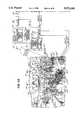
- FIGS. 1A and 1Btaken together, show a teleconferencing system according to one embodiment of this invention
- FIG. 2is a partly broken away top view of a first station of the teleconferencing system shown in FIG. 1A;
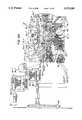
- FIGS. 3A and 3Btaken together, show another embodiment of the present invention wherein the stations have different predetermined sensory settings
- FIGS. 4A and 4Btaken together, show still another embodiment of the invention having stations which have predetermined sensory settings which are designed, decorated and defined to be complementary and/or substantially identical;
- FIGS. 5A and 5Btaken together, provide a visual illustration of the images corresponding to some of the signals generated by the teleconferencing system.
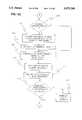
- FIGS. 6A-6Dtaken together, show a schematic diagram of a method according to an embodiment of this invention.
- a teleconferencing system 10having a first station or suite 12 and a second station or suite 14.
- the first station 12comprises a first conference or sensory area 16, and the second station 14 comprises a second conference or sensory area 18-1, respectively.
- the first and second stations 12 and 14also comprise a first video area 20 and a second video area 22-1, respectively, associated with the first and second conference areas 16 and 18-1.
- the first video area 20is generally integral with a wall 32h in the first station 12.
- the second video area 22-1is generally integral with a wall 32h-1 in the second station 14.
- the first and second stationsare geographically remote from each other, but they could be situated on the same premises if desired.
- the first station 12is shown assembled or constructed into a generally elongated octagonal shape.
- the first station 12comprises a plurality of modular members 32a-32h which include walls 32a, 32c-e, 32g-h, doors in wall members 32b and 32f and entry facade 32f-1.
- the first station 12also comprises a ceiling 34 (FIG. 1A) which is mounted on the members 32a-32h with suitable fasteners, such as nuts, bolts, adhesives, brackets, or any other suitable fastening means. Notice that the ceiling 34 has a dropped or sunken portion 34a which supports appropriate lighting fixtures 56.
- each of the members 32a-32h and the ceiling 34is molded or formed to provide or define an environment having a unique architectural setting and/or sensory setting.
- the wall member 32amay be formed to provide a plurality of stones 36, a plurality of columns 38, and an arch 40 to facilitate defining a first predetermined setting 12a having a Roman/Italian motif, theme or aura.
- One or more of the members 32a-32hmay be provided with inlays, wall decorations (like picture 58 in FIGS. 1A and 2), or even a permanent frosted glass window and frame arrangement 42 mounted therein.
- members 32b and 32f(FIG. 2) may be provided with sliding doors 44 which facilitate entering and exiting the first station 12 and which are designed to complement or further enhance the Roman/Italian motif.
- member 32h(FIGS. 1A and 2) is formed to provide a stone and pillar appearance and texture complementary to the stone and pillar appearance and texture of the wall members, such as member 32a.
- the member 32amay be shaped to frame or mask a rear projection screen 46, as shown. The function and operation of the rear projection screen 46 will be described later herein.
- the rear projection screen 46comprises a high resolution lenticular rear projection screen which is either integral with or mounted directly to member 32h to provide a first video area 20 having a usable projection area of about 52 inches by 92 inches with an associated aspect ratio of 16:9.
- Each of the members 32a-32h and ceiling 34are created in separate modular units using a plurality of molds (not shown).
- a suitable material for molding the members 32a-32h and ceiling 34 to provide a granite-like appearancemay be Gypsum, but they could be formed from other suitable material such as stone or clay-based materials, ceramic, paper, cardboard, foam, wood, Styrofoam and the like.
- the member 32dmay be provided with a shelf or mantle 33.
- the various members 32a-32hare assembled together as shown in FIG. 2 and secured together with suitable support braces 48 which may be secured to the walls 32a-32h with any suitable fastener such as screws, bolts, an adhesive or the like.
- the first station 12After the first station 12 is assembled and the ceiling 34 is secured thereto, it has a length of about 14 feet, 6 inches (indicated by double arrow L in FIG. 2) and a width of about 12 feet, 0 inches (indicated by double arrow W in FIG. 2).
- the first station 12has an approximate height from floor to ceiling 34 of about 8 feet, 6 inches.
- the members 32a, 32c, 32e and 32ghave a width (indicated by double arrow Y in FIG. 2) of about 5 feet, 0 inch.
- the back wall member 32d and front wall member 32hcomprises a width of about 7 feet, 8 inches (indicated by double arrow X in FIG. 2).
- the first station 12may be further decorated, designed or ornamented with a plurality of subjects, decorations or ornaments which facilitate providing the first predetermined sensory setting 12a which defines a first aura, motif or theme.
- the second station 14maybe further provided or ornamented with a plurality of subjects, decorations or ornaments which facilitate providing a second predetermined sensory setting 14a which defines a second aura, motif or theme.
- the predetermined sensory setting 12a of the first station 12may be further decorated with a table 50, table decorations, pillar and wall decorations, carpet (not shown), plants 54 and other wall decorations (not shown) to further enhance the Roman/Italian motif, theme or aura.
- the first and second predetermined sensory settings 12a and 14amay also comprise appropriate lighting fixtures 56 and appropriate furnishings, such as chairs 60 and tables 61, which complement the predetermined setting to further facilitate defining the Roman/Italian theme or motif for the stations 12 and 14.
- first and second stations 12 and 14are assembled and ornamented or decorated to provide their respective first and second predetermined sensory settings 12a and 14a, they define an aura, theme or motif which facilitates providing or creating a very sensual and impressionable environment.
- Providing such a station, such as station 12, with a strong sensory environmentfacilitates enhancing the virtual presence illusion created by teleconferencing system 10 of the present invention.
- first station 12 and second station 14are shown in the embodiment in FIGS. 1A and 1B as having complementary or similar first and second predetermined sensory settings 12a and 14a, they could be provided with first and second predetermined sensory settings 12a and 14a having different themes, motifs or auras.
- first and second predetermined sensory settings 12a and 14ahaving different themes, motifs or auras.
- FIGS. 1A and 1Billustrate a first and second set of stations 12 and 14 having a Roman/Italian motif
- another set of stationssuch as station 12' and station 14' in the embodiment illustrated in FIGS. 3A and 3B, may have at least one station having a different predetermined setting.
- the second station 14' in FIG. 3Bprovides a setting 14a' which defines a Chinese aura, theme or motif.
- the members 32a-32h, ceiling 34 and associated predetermined sensory settingare provided to be transportable and capable of being assembled at any suitable location, such as an existing rectangular room, suite or conference area having dimensions of at least 20 feet ⁇ 20 feet ⁇ 9 feet. While it may be desirable to provide the first and second stations 12 and 14 in the teleconferencing system 10 with substantially the same dimensions, it should be appreciated that they could be provided with differing dimensions, depending on, for example, the number of participants at each station. It should also be appreciated that the second station 14 and other stations described herein would preferably be manufactured and assembled in the same or similar manner as the first station 12.
- the teleconferencing system 10also comprises conferencing means or a conferencing system means for teleconnecting the first and second stations 12 and 14 together to facilitate capturing an image or images at one of said stations and displaying at least a portion of the image or a sub-image at another of the stations such that it becomes generally visually integrated with the predetermined sensory setting at that station, thereby facilitating creating a "video mirror" and a "face-to-face” environment for the participant situated at that station.
- the conferencing system associated with the first station 12comprises image sensor means, imager or image sensors for sensing images at the first station 12.
- the image sensor meanscomprises a plurality of cameras which are operably associated with the rear projection screen 46 of first station 12.
- the plurality of camerascomprise a first camera head 62 and second camera head 64 which are operatively coupled to a first camera control unit 66 and second camera control unit 68, respectively.
- first and second camera control units 66 and 68are remotely situated from the first and second camera heads 62 and 64. This facilitates permitting the first and second cameras 62 and 64 to be placed directly in the projection path of the rear projection screen 46, without substantially interfering with the video image being projected.
- the first camera head 62 and second camera head 64are situated approximately 16 inches above the surface of table 50 which generally corresponds to the eye level of the seated participants situated at table 50.
- the first and second cameras 62 and 64are situated behind the rear projection screen 46 in operative relationship with a pair of 11/4 inch diameter openings 66 and 68, respectively.
- the first and second cameras 62 and 64are mounted on a suitable narrow or non-interfering bracket (not shown) such that they can be positioned behind the rear projection screen 46 in operative relationship with openings 66 and 68, respectively.
- the first and second cameras 62 and 64are 11/4 inch by 11/4 inch 3-CCD camera heads which generate images having an aspect ratio of about 3:4 and a picture resolution of about 494 ⁇ 700 pixels.
- One suitable 3-CCD camera heads 62 and 64 and associated camera control units 66 and 68may be Model No. GP-US502 manufactured by Panasonic Broadcast and Television Systems Company of Japan. It should be appreciated that while the teleconferencing system 10 shown and described in relation to FIGS. 1A and 1B show image sensor means comprising a plurality of camera heads 62 and 64 and camera control units 66 and 68 situated at a station, a single camera may be used (as shown and described relative to the embodiment shown in FIGS.
- the camera heads 62 and 64 and associated camera control units 66 and 68are configured and positioned at the first station 12 to facilitate providing maximum vertical eye contact among participates in the teleconference, while minimally interrupting the substantially life-size video projection on the rear projection screen 46.
- the conferencing meansalso comprises a first differentiator or differential key generator 70 (FIG. 1A) and a second differentiator or differential key generator 72, respectively.
- the camera control unit 66generates an RGB analog signal I-62 which is received by the first differentiator 70
- the camera control unit 68generates an RGB signal I-64 which is received by the second differentiator 72.
- the first and second differentiators 70 and 72provide means for processing the image signals generated by the camera control units 66 and 68 to remove or differentiate any undesired portion of the images corresponding to the signals I-62 and I-64.
- the image of the participants situated at the first station 12from at least a portion of the first predetermined sensory setting 12a, such as the background behind the participants, in order to provide a differential signal VS-1 that has that portion of the first predetermined sensory setting 12A removed.
- Thisfacilitates transmitting the video image of the participants at the first station 12 to the remote second station 14 and also facilitates compositing the image with other images, as described below.
- Suitable differentiators 70 and 72may comprise the differential key generator shown and described in U.S. Pat. No. 4,800,432, issued on Jan. 24, 1989 to Barnett et al. and assigned to The Grass Valley Group, Inc., which is incorporated herein by reference and made a part hereof.
- the differential key generators 70 and 72convert the I-62 and I-64 signals from RGB analog signals to digital image signals having corresponding images 104 and 106 (FIG. 5A), respectively.
- the differential key generators 70 and 72compare the digital image signals to an associated differential reference signals DRS-62 and DRS-64, respectively, which generally corresponds to images 108 and 110 in FIG. 5A. As described in detail later herein, these images 108 and 110 comprise at least a portion of the first predetermined sensory setting 12a such as the background.
- the differential reference signals DRS-62 and DRS-64are stored in appropriate storage 74 and 76 (FIG. 1A) associated with the differential key generators 70, 72, respectively.
- the differential reference signals DRS-62 and DRS-64comprise a reference frame of a video image grabbed by one or both cameras 62 or 64 situated at the first station 12 from a video sequence of the first predetermined sensory setting 12a of the first station 12 background where no participants, chairs, or other foreground elements are in place.
- the first and second differentiators 70 and 72In response to the comparison, the first and second differentiators 70 and 72 generate differentiated video signals VS-1 and VS-2 (FIG. 1A), respectively.
- the VS-1 and VS-2 signalsgenerally correspond to the individuals situated at the first station 12 when viewed in the direction of arrow A in FIG. 2.
- the images 112 and 114FIG. 5 associated with the VS-1 and VS-2 signals, respectively, notice that the background area shown in images 104 and 106 has been removed and is tagged as a "zero" image area.
- tagging at least a portion of the image represented by the VS-1 signal as "zero" backgroundfacilitates compressing the VS-1 and VS-2 signals and providing corresponding compressed CDS-1 and CDS-2 signals, thereby reducing the amount of transmission band width needed.
- This taggingalso facilitates compositing or overlaying another predetermined image to provide a seamless composited image as described in detail below.
- the video signals VS-1 and VS-2are received by a first compression/decompression means or CODEC 78 and a second compression/decompression means or CODEC 80, respectively.
- the CODECs 78 and 80also receive an audio signal AS-A1 and AS-A2 from suitable microphones 82 and 83, respectively, which may be positioned or concealed at an appropriate location in the first station 12, such as underneath or on top of table 50, as illustrated in FIG. 1A.
- the function of the first and second CODEC 78 and 80is to compress video and audio signals for transmitting to remote stations, such as the second station 14, and also to decompress compressed video and audio signals received from remote stations.
- the CODECs 78 and 80are configured with suitable compression and decompression algorithms which are known to those of ordinary skill in the art.
- the CODEC Model No. Rembrandt II VP available from Compression Labs, Inc. of San Jose, Calif.is suitable for use in the embodiment described herein, but it should be noted that other suitable compression/decompression means may be employed.
- the CODEC 78receives the video signal VS-1 and audio signal AS-A1
- CODEC 80receives the video signal VS-2 and audio signal AS-A2.
- the CODECs 78 and 80generate digital signals CDS-1 and CDS-2, respectively, in response thereto which are in turn transmitted to remote station 14 via a transmission network 84.
- the transmission network 84may be configured as a private network, public circuit switch service, and it may utilize telecommunication and/or satellite technology.
- the transmission network 84preferably includes a plurality of T-1 lines (not shown) which are capable of accommodating bit streams having a suitable band width, such as 1.544 megabytes per second.
- the teleconferencing system 10 and conference means associated with the first station 12also comprises enhancing means for enhancing the resolution of an image or sub-image received from a remote station, such as the second station 14.
- enhancing meanscomprises a first line doubler 86 and a second line doubler 88 which are operatively coupled to the first CODEC 78 and second CODEC 80, respectively.
- the first and second line doublers 86 and 88enhance the resolution and picture quality of at least a portion of the image corresponding to video signals VS-3 and VS-4 received from the CODECs 78 and 80, respectively, by about 50-150%.
- the VS-3 and VS-4 signalscorrespond to images or sub-images received from remote station(s), such as station 14, as described in detail below.
- One suitable line doubleris the Model No. LD 100 available from Faroudja Laboratories, Inc. of Sunnyvale, Calif., but other suitable enhancing means may be provided to provide greater or less enhancement of the images to be displayed.
- suitable enhancing meansmay be provided to provide greater or less enhancement of the images to be displayed.
- lenses, mirrors, optical pixel interpolation or other electrical meansmay be employed as desired.
- the present inventionmay be performed without the use of any enhancing means without departing from the scope of the invention.
- the first and second line doublers 86 and 88generate enhanced video signals which are input into compositing means, compositor or video compositing multiplexer 92 for compositing the enhanced video signals associated with the images or sub-images received from the remote station(s) with one or more predetermined composite signals, such as predetermined composite signal A, corresponding to a predetermined composite image or sub-image which are stored in a suitable storage device 94 associated with the compositor 92.
- the predetermined composite signal Acorresponds to an image of at least a portion of first predetermined sensory setting 12a, such as the background of the first station 12.
- the video compositing multiplexer 92composites the signals received from the first and second line doublers 86 and 88 with the predetermined composite signal A and generates a RGB analog composite signal in response thereto. It has been found that Model No. E-Space-1 available from Miranda Technologies, Inc. of Montreal and Quebec, Canada, is one suitable video compositing multiplexer 92.
- the teleconferencing system 10comprises a projector 96 coupled to the video compositing multiplexer 92 which receives the RGB composite signal and projects a corresponding image 90 (FIG. 1A) corresponding to the composite signal on the rear projection screen 46.
- the Model No. 3300 available from AMPRO Corporation of Titusville, Fla.has been found to be a suitable projector 96.
- a liquid crystal display (LCD) or other electronic screenmay be suitable to display images at a station. This may eliminate the need for the projector 96.
- the projector 96could be used with an optical system or a plurality of mirrors (not shown), or prisms (not shown) such that the projector can be positioned, for example, to the side or below the rear projection screen 46 or in a manner that permits the projector 96 to project the image towards a mirror (not shown), which causes the image to be projected on the rear projection screen 46.
- the composite signal and its corresponding image 90generally comprise a video image of at least a portion of the first predetermined sensory setting 12a combined or composited with a differentiated image, such as an image of the participants from the second station 14 which correspond to the VS-3 and VS-4 (FIG. 1B) signals. Consequently, the resultant image 90 projected on screen 46 at the first station 12 complements or blends with the architectural motif, aura, theme or design defined by the first predetermined sensory setting 12a at the first station 12, such that the projected image 90 appears visually integrated with the first predetermined sensory setting 12a of the first station 12.
- the sub-images or images received from the remote station(s)typically have a resolution on the order of about 352 ⁇ 288 pixels and the predetermined composite signal A comprises a resolution on the order of about 1280 ⁇ 1024 pixels.
- the resultant composite image 90may comprise, for example, an image of the participants situated at the second station 14 having a first resolution and a background image of the first station 12 having a second resolution, which is higher than the first resolution. This enables compositor 92 to provide a composite image 90 which, when displayed on screen 46, gives the illusion or effect of a "video mirror" to the participants situated at the first station 12.
- the teleconferencing system 10also includes audio means comprising a plurality of speakers 100 and 102 (FIGS. 1A and 2) which, in turn, receive audio signals AS-B1 and AS-B2 from CODECs 78 and 80, respectively.
- audio signal AS-B1 and AS-B2generally correspond to the audio associated with the sound (e.g., voices, music and the like) associated with the remote station(s), such as second station 14.
- the rear projection screen 46 and projector 96are configured and selected to enable the teleconferencing system 10 to project the composited image 90 (FIG. 1A) at a predetermined scale, such as substantially full scale.
- the compositor 92comprises a scaler 95 which is integral therewith for scaling the composited signal associated with the composited image 90 to a desired or predetermined scale, such as substantially full scale.
- the second station 14comprises similar components as the first station and such like components are labelled with the same reference numeral as their corresponding component in the first station 12, except that the components associated with the second station 14 have a "-1" designator added thereto.
- Such componentsoperate and function in substantially the same manner as described above with regard to the first station 12 with the following being some differences.
- the differential reference signals DRS-3 and DRS-4 (FIG. 5) associated with the second station 14generally correspond to an image or sub-image of at least a portion of the second predetermined sensory setting 14a, such as the background 98-1, of the second station 14.
- Such sub-image or imagemay include at least a portion of the background 98-1 without any participants, chairs or other foreground subjects situated in the second station 14.
- a predetermined composite signal Bmay be stored in the storage 94-1 associated with the compositor 92-1 second station 14.
- the predetermined composite signal Bmay correspond to an image or sub-image of at least a portion of the second predetermined sensory setting 14a of the second station 14.
- Such sub-image or imagemay include, for example, an image of the walls 32a-1 to 32h-1 and conference area 18 or background of the second station 14.
- the second station 14has a second predetermined sensory setting 14a which mirrors or is complementary to the first predetermined sensory setting 12a.
- the first and second predetermined sensory settings 12a and 14amay be different.
- FIGS. 6A-6DA method of operating the teleconferencing system 10 will now be described in relation to FIGS. 6A-6D.
- the modular componentssuch as members 32a to 32h and ceiling 34 for first station 10, decorations and the like, are configured, assembled and decorated (block 99 in FIG. 6A) at a desired location to provide a conference station comprising a predetermined sensory setting defining a predetermined theme, motif or aura.
- the theme, motif or auramay be complementary (as shown in FIGS. 1A and 1B) or they can be completely different, as shown in FIGS. 3A and 3B (described below).
- FIGS. 3A and 3BAs ease of illustration, it will be assumed that the stations are assembled and decorated as shown and described relative to the embodiment in FIGS. 1A and 1B.
- the modular stations 12 and 14are assembled and decorated, it may be desired (decision point 101 in FIG. 6A) to use differentiator (e.g., differentiator 72 in FIG. 1A). As discussed herein relative to the embodiments shown in FIGS. 4A and 4B, it may not always be desired to generate a differential reference image, thereby making it unnecessary to generate the differential reference signal. If differentiation is desired, then the camera heads 62 or 64 generate at least one video image (block 103) of at least a portion of the first predetermined sensory setting 12A at the first station 12. The differentiators 72 and 74 grab or capture at least one differential reference image or sub-image from those images and generate (block 107) the differential reference signals DRS-62 and DRS-64, respectively.
- differentiator 72 in FIG. 1AAs discussed herein relative to the embodiments shown in FIGS. 4A and 4B, it may not always be desired to generate a differential reference image, thereby making it unnecessary to generate the differential reference signal.
- the camera heads 62 or 64generate at least one video image
- signalsare stored in suitable storage 74 and 76 for use by the differentiators 70 and 72, respectively.
- cameras 62-1 and 64-1 at the second station 14generate video images of at least a portion of the second predetermined setting 14a at the second station 14.
- the differentiators 70-1 and 72-1grab or capture at least one differential reference image or sub-image from those images and generate differential reference signals (not shown) corresponding thereto.
- These signalsare then stored (block 109) in suitable storage 74-1 and 76-1 for use by differential key generators 70-1 and 72-1, respectively.
- the differential reference signals DRS-62 and DRS-64comprise an image of at least a portion of the first predetermined sensory setting 12a, such as an image of the first station 12 without any participants, chairs or other subjects which are not stationary during the teleconference.
- the differential reference signals associated with the differentiators 70-1 and 72-1comprise at least a portion of the second predetermined sensory setting 14a at the second station 14, such as an image of the background 98-1 without the participants, chairs and other subjects which are not stationary during the teleconference.
- Such predetermined composite imagewould preferably include a substantial portion of the first predetermined sensory setting 12a, including the background and/or conference area 16 of the first station 12. If compositing is desired, then the predetermined composite signal A is generated (block 111 in FIG. 6B). The corresponding predetermined composite signal A may then be stored in suitable storage 94. In the same manner, the predetermined composite image at the second station 14 and corresponding predetermined composite signal B may be generated and stored as predetermined composite signal B in suitable storage 94-1. In the embodiment being described, the predetermined composite image associated with the second station 14 includes an image of at least a portion of the second predetermined sensory setting 14a, including the background 98-1.
- the predetermined composite signals A and Bare generated by a suitable still camera (not shown) to provide a still image (not shown) of the station 12 or 14 being photographed.
- the still imagewould subsequently be scanned and digitized for storage by a suitable scanner (not shown).
- the still camera and scannerwould preferably be capable of generating images having a resolution on the order of about 1280 ⁇ 1024 pixels.
- the resultant composite image(such as image 90 in FIG. 1A) may comprise an image having a high resolution background, for example, combined with a comparatively lower resolution image of the remote station participants. This, in turn, facilitates enhancing the "video mirror" effect wherein a mimic or replication of a common architectural technique of mirroring a wall of a given room which makes the overall room appear to be extended beyond its actual wall line.
- the first and second suites 12 and 14may then be teleconnected (block 113) or connected by satellite or other suitable means via the transmission network 84.
- one or more participantsmay be situated at the first and second stations 12 and 14. As illustrated in FIG. 2, notice that the participants seated at the first station 12 are situated a predetermined distance B from a participant's side 46a of the rear projection screen 46.
- the predetermined distance Bgenerally corresponds to a preferred or optimum focal distance at which optimum imaging by cameras 62 and 64 may be performed. In the embodiment being described, it has been found that the predetermined distance should be about 5 feet, 6 inches.
- the participantsare situated at the second station 14 in a similar manner and the face-to-face teleconference may then begin.
- the first and second cameras 62 and 64capture (block 117 in FIG. 6B) live images of the participants situated at the first station 12 and generate corresponding RGB analog signals I-62 and I-64 which are received by the differential key generators 70 and 72, respectively. If differentiation was selected (decision point 147 in FIG. 6C), processing continues at block 119 otherwise it proceeds at block 123.
- the differential key generators 70 and 72generate (block 121 in FIG. 6C) the digital differential signal VS-1 and VS-2, respectively, after comparing (block 119 in FIG. 6C) the I-62 and I-64 signals received from cameras 62 and 64 to their respective differential reference signals DRS 62 and DRS-64 which are received from storages 74 and 76.
- the differential signals VS-1 and VS-2are then received by CODECs 78 and 80 which also receive the audio signals AS-A1 and AS-A2 which correspond to the audio, including sounds, music and voices, associated with the first station 12.
- the CODECs 78 and 80digitize the audio signals AS-A1 and AS-A2, combine the audio signals with their respective video signal VS-1 or VS-2, and generate (block 123) the compressed CDS-1 and CDS-2 signals in response thereto.
- the CDS-1 and CDS-2 signalsare then transmitted (block 125) to the second station 14 via the transmission network 84 (FIG. 1B).
- the CDS-1 and CDS-2 signalsare received and decompressed (block 127 in FIG. 6C) by CODECs 78-1 and 80-1, respectively, associated with the second station 14 to provide decompressed VS-1 and VS-2 signals.
- the CODECs 78-1 and 80-1also decompress the audio signals AS-A1 and AS-A2 received from the first station 10 which are transmitted to speakers 100-1 and 102-1, respectively, at the second station 14.
- CODECs 78-1 and 80-1decompress the CDS-1 and CDS-2 signals to provide VS-1 and VS-2 signals.
- the decompressed video signals VS-1 and VS-2are then received by line doublers 86-1 and 88-1. If it is desired to enhance the signals (decision point 129), then the line doublers 86-1 and 88-1 process or manipulate the signals (block 131) in order to enhance the resolution of the image corresponding to those signals. After the signals VS-1 and VS-2 are processed, it may be desired to composite (decision point 133 in FIG. 6D) those signals with one or more other signals.
- the video compositor 92-1composites images (block 135) corresponding to those signals with at least one predetermined composite image, such as image 122 (FIG. 5B) corresponding to the predetermined composite signal B provided from storage 94-1 (FIG. 1B) to provide a composite signal.
- the composite signalgenerally corresponds to the composited image 91-1 to be displayed on the rear projection screen 46-1 at the second station 14.
- the compositor 92-1may (decision point 137, block 139 in FIG. 6D) scale the composited image to a desired scale, such as full scale, using scaler 95-1. Thereafter, the compositor 95-1 transmits a corresponding RGB analog signal to projector 96-1 which displays (block 141) the scaled, composited image on the rear projection screen 46-1 (FIG. 1B).
- the teleconferencemay then be continued or terminated as desired (decision point 143, block 145).
- the composited imageis substantially full scale when projected and includes a high resolution image of at least a portion of the second predetermined sensory setting 14a, the image appears to blend or become visually integrated with the second predetermined sensory setting 14a. This, in turn, gives the participants situated at the second station 14 the perception that the first station participants are present or face-to-face with them in the second station 14.
- images and signals relative to the second station 14 imagesare captured, processed and displayed at the first station 12. So that images of the participants at the second station 14 are displayed at the first station 12 such that they appear to have a face-to-face presence at the first station 12.
- images of the second station 14 participantsmay be differentiated and composited such that, when they are displayed at the first station 12, the image completes or provides "the other half" of the first station 12 and becomes generally visually integrated therewith.
- it may be desirable to enhance the face-to-face presenceby providing, for example, first and second predetermined sensory settings 12a and 14a which define a dining environment wherein food or meals may be served.
- the face-to-face presencemay be further enhanced if the participants at both stations 12 and 14 order food and drinks from identical menus.
- trained maitre-de and/or waitersmay be used to actively promote the perception of a face-to-face dinner using a scripted dialog and interaction with remote participants, maitre-de and/or waiters.
- the stations 12 and 14may be used by the same or different participants without the need to reconstruct or reassemble the stations.
- FIGS. 5A and 5Bprovide a visual illustration of the images corresponding to some of the signals described above utilizing the method and embodiment described above.
- images 104 and 106generally correspond to the actual images captured by the first and second cameras 62 and 64, respectively.
- associated image signals I-62 and I-64are transmitted to the differential key generators 70 and 72, respectively.
- the differential key generators 70 and 72compare the images 104 and 106 to the images 108 and 110 associated with the differential reference signals DRS-62 and DRS-64 which are received from storages 74 and 76, respectively, and which were previously generated by cameras 62 and 64 from an identical fixed camera position.
- the differential key generators 70 and 72generate differential signals VS-1 and VS-2 which have corresponding images 112 and 114. Notice that these images 112 and 114 comprise an image of the participants which are situated at the first station 12 with the background area having been removed or tagged as a "zero" area. As described herein, this "zero" area becomes "filled-in” with the desired or predetermined composite image which may include, for example, an image of at least a portion of the predetermined setting or background of the second station 14.
- the video signals VS-1 and VS-2are fed into CODECs 78 and 80 which compresses the signals along with audio signal AS-A1 and AS-A2 and generates signals CDS-1 and CDS-2.
- the CDS-1 and CDS-2 signalsare then transmitted, via transmission network 84, to the second station 14 and received by the CODECs 78-1 and 80-1 associated with the second station 14.
- the CODEC 78-1 and 80-1decompresses the CDS-1 and CDS-2 signals, respectively, from the first station 12 and feeds them into associated line doublers 86-1 and 88-1.
- the line doublers 86-1 and 88-1facilitate enhancing the images associated with the video signals to provide enhanced video signals EVS-1 and EVS-2 (FIG. 5B), respectively.
- the enhanced video signals EVS-1 and EVS-2are then received by the video compositing multiplexer 92-1 associated with the second station 14 wherein the signals are combined to provide an intermediate composite signal ICS having an associated intermediate composite signal image 120 having an aspect ratio of about 8:3.
- the video compositing multiplexer 92-1also receives the predetermined composite signal B having a predetermined composite signal B image 122 from storage 94-1.
- the video compositing multiplexer 92-1composites or combines the images 120 and 122 to generate the composite signal having an associated or corresponding composite image 124 as shown in FIG. 5B.
- the predetermined composite signal B image 122generally corresponds to at least a portion of the predetermined setting or background of the second station 14 and has an aspect ratio of 16:9.
- the video compositing multiplexer 92-1causes the "zero" area of the intermediate composite signal image 120 to be "filled in” with the predetermined composite signal B image.
- the composite image 124may then be scaled to a predetermined size or scale, such as full scale, using scaler 94-1, so that the composite image 124 may be scaled to a substantially full scale or real-life size image as desired.
- the composite image signal corresponding to the composite image 124is transmitted to the projector 96-1 and then displayed on the rear projection screen 46-1 at the second station 14.
- the composite image 124may be appropriately framed or masked (such as with an archway 125 in FIGS. 1B and 5B) when it is projected at the second station 14 to enhance the face-to-face, real time environment.
- the audio and video signals transmitted between the first and second stations 12 and 14may be, in this illustration, transmitted over separate T-1 lines (not shown) in the transmission network 84 in order to effect a substantially simultaneous and/or "real time" video conference.
- the participantsmay be geographically remotely located, yet the participants situated at the first station 12 will feel as if the second station 14 participants are located face-to-face or present with them at the first station 12, while the participants situated at the second station 14 will feel as if the first station participants are face-to-face or present with them at the second station.
- predetermined composite signal B and associated predetermined composite signal image 122is composited with the intermediate composite signal and associated intermediate composite signal image 120, it overlays that signal to provide a seamless composite image 124, which facilitates reducing or eliminating the need to match up the borders or seams of the camera images with any high degree of accuracy.
- cameras 62 and 64 and 62-1 and 64-1preferably be situated such that they capture an entire participant rather than, for example, half of a participant. Thus it may be desired to position the participants in a location such that any particular participants will not be in the field of view of more than one camera.
- the inventionprovides an apparatus and method for providing a video mirror at each station 12 and 14 which facilitates creating a face-to-face and non-interrupted image of any participants in the video conference. Because the image of the participants is differentiated, less transmission bandwidth, computer memory and the like is required. Also, the differentiators and compositors of the present invention enable a user to create a composite image 124 (FIG. 5B) having at least a portion thereof imaged at a greater resolution than the portion which was transmitted over transmission network 84. This facilitates reducing the effect of limitations or transmission restrictions of the transmission network 84 which, in turn, facilitates increasing the quality of images displayed at a station.
- the composite image 124may have an aspect ratio which is different from the aspect ratio of the cameras 62 and 64.
- Thisenables the system and method of the present invention to utilize cameras which generate images having smaller or even larger aspect ratios.
- Thisalso enables the system and method to use cameras having standard or common aspect ratios, such as 4:3.
- FIGS. 3A and 3Bwhen taken together, illustrate another embodiment of the invention.
- the operation and components of the embodiment shown in FIGS. 3A and 3Bare substantially the same as the operation of components of the embodiment described above relative to FIGS. 1A and 1B with the same reference numerals being used for the same components with the addition of single prime (') designator. Consequently this embodiment is similar to the embodiment shown in FIGS. 1A and 1B, except that the second predetermined setting 14a' in FIG. 3B and its associated theme, aura or motif is substantially different from the second predetermined setting 14a shown in FIG. 1B.
- the first predetermined sensory setting 12a'comprises a plurality of decorations 120 defining the Chinese theme, motif or aura.
- the predetermined composite signal A stored in storage 94-1' and the differential reference signals stored in storages 74-1' and 76-1would generally correspond to an image of least a portion of that setting 14a'.
- an image of the participants situated at the first station 12'is composited by compositor 92-1' with a predetermined composite image of at least a portion of the second predetermined sensory setting 14a' of the second station 14' and projected onto the rear projection screen 46-1' at the second station 14'.
- the first station 12' participantsappear to be face-to-face with the second station 14' participants because they have a relatively high resolution video image behind them which complements or becomes integrated with the second predetermined sensory setting 14a'.
- the image 91-1' (FIG. 3B) of the ladies at the first station 12'includes a Chinese background which blends or complements the actual predetermined sensory setting 14a'.
- FIGS. 4A and 4Bwhen taken together, illustrate another embodiment of the invention.
- the components of the embodiment shown in FIGS. 4A and 4Bwhich are substantially identical to the components in the embodiment shown in FIGS. 1A and 1B which have the same reference numerals with the addition of a double prime ("''") designators.
- two remote modular stationssuch as stations 12'' and 14'' may be provided and designed to have first and second predetermined sensory settings 12a'' and 14a'' which are substantially identical.
- stations 12'' and 14''may be provided and designed to have first and second predetermined sensory settings 12a'' and 14a'' which are substantially identical.
- imagesmay be captured in the manner described above at station 12'' received by CODECs 78'' and 80'' and then transmitted, via transmission 84'', to associated CODECs 78-1'' and 80-1'', respectively.
- the CODECs 78-1'' and 80-1''then generate a decompressed signal which may be enhanced by line doublers 86-1'' and 88-1'', respectively; scaled to an appropriate scale by scaler 95-1''; and then projected by projector 96-1'' onto rear projection screen 46-1''.
- this embodimentdoes not utilize the differentiating and compositing features of the previous embodiment, but may still achieve a face-to-face conference environment because the second predetermined sensory setting 14a'' is configured to be identical to or complementary with the first predetermined sensory setting 12a''.
- entire images or sub-images of the stations 12 and 14are displayed at remote station(s). Because the stations 12'' and 14'' are assembled, decorated and designed to be complementary or identical, they appear visually integrated to participants situated in the stations 12 and 14.
- the first and second predetermined sensory settings 12a" and 14a", including the background,are designed and arranged in a geometric fashion such that as cameras 62" and 64" capture images of the participants, they also capture images of the first and second predetermined sensory setting 12a" and 14a", respectively, at the most advantageous perspective for display at the remote station(s).
- thiscauses the first station 12'' participants to perceive that the second station 14'' participants are situated or present with the first station 12'' participants at the first station 14''.
- the first station 12'' participantsappear to be face-to-face with the second station 14'' participants at the second station 14'' when the images associated with the first station 12'' are displayed on screen 46-1''.
- a face-to-face conferencemay be created.
- itmay also be desired to differentiate, enhance, composite or scale the images as described with previous embodiments, but this is not required with the embodiment being described.
- stationscan be provided with predetermined settings which are completely different, yet, by utilizing the apparatus and method of the present invention, the images of the participants in these stations may be projected at remote stations so that they appear to be virtually face-to-face with the remote station participants at or one more remote station.
- the screen 46 for station 12has been shown as being integral with a portion of a wall 32h (FIGS. 1A and 2A), it could comprise a larger or smaller portion of that wall 32h, or it could be provided as part of one or more other walls, or even as part of the ceiling 34.
- one or more of the compositorsmay comprise a stationary or moving image database (not shown) for providing a plurality of predetermined composite signals which define a particular or desired video background.
- a stationary or moving image databasefor providing a plurality of predetermined composite signals which define a particular or desired video background.
- participantsmay elect to use the arched background of their proximity, choose an event-related scene, or decide to meet in a setting completely unrelated to their site or station.
- a station having a Manhattan eatery motifmay be provided with a screen configured as a window (not shown).
- Certain moving video backgrounds of a busy New York avenuemay be deposited and displayed on the screen to give the illusion that the participants situated at the station are dining in a popular Manhattan eatery.
- the predetermined settingscould define any type of aura, theme or motif which is suitable for video conferencing and in which it is desired to provide a "real-life" or face-to-face presence illusion.
- the apparatus and method of this inventioncould be used in a business setting, education setting, seminar setting, home environment, religious setting, celebration setting (such as a birthday, retirement party, holiday or anniversary), or any other suitable setting as desired.
Landscapes
- Engineering & Computer Science (AREA)
- Multimedia (AREA)
- Signal Processing (AREA)
- Two-Way Televisions, Distribution Of Moving Picture Or The Like (AREA)
- Telephonic Communication Services (AREA)
- Input Circuits Of Receivers And Coupling Of Receivers And Audio Equipment (AREA)
- Cosmetics (AREA)
- Computer And Data Communications (AREA)
- Data Exchanges In Wide-Area Networks (AREA)
Abstract
Description
Claims (73)
Priority Applications (18)
| Application Number | Priority Date | Filing Date | Title |
|---|---|---|---|
| US08/308,603US5572248A (en) | 1994-09-19 | 1994-09-19 | Teleconferencing method and system for providing face-to-face, non-animated teleconference environment |
| AU36344/95AAU697578B2 (en) | 1994-09-19 | 1995-09-18 | Teleconferencing method and system |
| AT01128723TATE311724T1 (en) | 1994-09-19 | 1995-09-18 | METHOD AND SYSTEM FOR CONDUCTING VIDEO CONFERENCES |
| AT95933837TATE220838T1 (en) | 1994-09-19 | 1995-09-18 | METHOD AND DEVICE FOR CONDUCTING TELECONFERENCES |
| KR1019970701789AKR100403885B1 (en) | 1994-09-19 | 1995-09-18 | Teleconferencing method and system |
| EP95933837AEP0806115B1 (en) | 1994-09-19 | 1995-09-18 | Teleconferencing method and system |
| PCT/US1995/011802WO1996009722A1 (en) | 1994-09-19 | 1995-09-18 | Teleconferencing method and system |
| DE69534660TDE69534660T2 (en) | 1994-09-19 | 1995-09-18 | Method and system for video conferencing |
| DE69527440TDE69527440T2 (en) | 1994-09-19 | 1995-09-18 | METHOD AND DEVICE FOR HOLDING TELECONFERENCES |
| CA002200477ACA2200477C (en) | 1994-09-19 | 1995-09-18 | Teleconferencing method and system |
| EP01128723AEP1187480B1 (en) | 1994-09-19 | 1995-09-18 | Teleconferencing method and system |
| JP8511000AJPH10508990A (en) | 1994-09-19 | 1995-09-18 | Communication conference method and system |
| US08/740,839US5751337A (en) | 1994-09-19 | 1996-11-04 | Teleconferencing method and system for providing face-to-face, non-animated teleconference environment |
| US09/047,771US6160573A (en) | 1994-09-19 | 1998-03-25 | Teleconference method and system for providing face-to-face teleconference environment |
| US09/695,460US6445405B1 (en) | 1994-09-19 | 2000-10-24 | Teleconferencing method and system |
| US10/233,363US6654045B2 (en) | 1994-09-19 | 2002-08-30 | Teleconferencing method and system |
| US10/716,972US7116350B2 (en) | 1994-09-19 | 2003-11-19 | Teleconferencing method and system |
| US11/537,177US20070120954A1 (en) | 1994-09-19 | 2006-09-29 | Teleconferencing method and system |
Applications Claiming Priority (1)
| Application Number | Priority Date | Filing Date | Title |
|---|---|---|---|
| US08/308,603US5572248A (en) | 1994-09-19 | 1994-09-19 | Teleconferencing method and system for providing face-to-face, non-animated teleconference environment |
Related Child Applications (1)
| Application Number | Title | Priority Date | Filing Date |
|---|---|---|---|
| US08/740,839ContinuationUS5751337A (en) | 1994-09-19 | 1996-11-04 | Teleconferencing method and system for providing face-to-face, non-animated teleconference environment |
Publications (1)
| Publication Number | Publication Date |
|---|---|
| US5572248Atrue US5572248A (en) | 1996-11-05 |
Family
ID=23194627
Family Applications (7)
| Application Number | Title | Priority Date | Filing Date |
|---|---|---|---|
| US08/308,603Expired - LifetimeUS5572248A (en) | 1994-09-19 | 1994-09-19 | Teleconferencing method and system for providing face-to-face, non-animated teleconference environment |
| US08/740,839Expired - LifetimeUS5751337A (en) | 1994-09-19 | 1996-11-04 | Teleconferencing method and system for providing face-to-face, non-animated teleconference environment |
| US09/047,771Expired - LifetimeUS6160573A (en) | 1994-09-19 | 1998-03-25 | Teleconference method and system for providing face-to-face teleconference environment |
| US09/695,460Expired - LifetimeUS6445405B1 (en) | 1994-09-19 | 2000-10-24 | Teleconferencing method and system |
| US10/233,363Expired - Fee RelatedUS6654045B2 (en) | 1994-09-19 | 2002-08-30 | Teleconferencing method and system |
| US10/716,972Expired - Fee RelatedUS7116350B2 (en) | 1994-09-19 | 2003-11-19 | Teleconferencing method and system |
| US11/537,177AbandonedUS20070120954A1 (en) | 1994-09-19 | 2006-09-29 | Teleconferencing method and system |
Family Applications After (6)
| Application Number | Title | Priority Date | Filing Date |
|---|---|---|---|
| US08/740,839Expired - LifetimeUS5751337A (en) | 1994-09-19 | 1996-11-04 | Teleconferencing method and system for providing face-to-face, non-animated teleconference environment |
| US09/047,771Expired - LifetimeUS6160573A (en) | 1994-09-19 | 1998-03-25 | Teleconference method and system for providing face-to-face teleconference environment |
| US09/695,460Expired - LifetimeUS6445405B1 (en) | 1994-09-19 | 2000-10-24 | Teleconferencing method and system |
| US10/233,363Expired - Fee RelatedUS6654045B2 (en) | 1994-09-19 | 2002-08-30 | Teleconferencing method and system |
| US10/716,972Expired - Fee RelatedUS7116350B2 (en) | 1994-09-19 | 2003-11-19 | Teleconferencing method and system |
| US11/537,177AbandonedUS20070120954A1 (en) | 1994-09-19 | 2006-09-29 | Teleconferencing method and system |
Country Status (9)
| Country | Link |
|---|---|
| US (7) | US5572248A (en) |
| EP (2) | EP0806115B1 (en) |
| JP (1) | JPH10508990A (en) |
| KR (1) | KR100403885B1 (en) |
| AT (2) | ATE311724T1 (en) |
| AU (1) | AU697578B2 (en) |
| CA (1) | CA2200477C (en) |
| DE (2) | DE69534660T2 (en) |
| WO (1) | WO1996009722A1 (en) |
Cited By (178)
| Publication number | Priority date | Publication date | Assignee | Title |
|---|---|---|---|---|
| WO1997022918A1 (en)* | 1995-12-20 | 1997-06-26 | Mediamaxx Incorporated | Computer-controlled system for producing three-dimensional navigable photographs of areas and method thereof |
| US5751337A (en)* | 1994-09-19 | 1998-05-12 | Telesuite Corporation | Teleconferencing method and system for providing face-to-face, non-animated teleconference environment |
| US5754190A (en)* | 1995-06-07 | 1998-05-19 | Advanced Micro Devices | System for reproducing images utilizing image libraries |
| US5757424A (en)* | 1995-12-19 | 1998-05-26 | Xerox Corporation | High-resolution video conferencing system |
| US5796394A (en)* | 1995-10-03 | 1998-08-18 | Sony Corporation | User interface and rule processing for a personal communications routing system |
| US5808613A (en)* | 1996-05-28 | 1998-09-15 | Silicon Graphics, Inc. | Network navigator with enhanced navigational abilities |
| US5815197A (en)* | 1995-02-16 | 1998-09-29 | Sumitomo Electric Industries, Ltd. | Two-way interactive system, terminal equipment and image pickup apparatus having mechanism for matching lines of sight between interlocutors through transmission means |
| US5818616A (en)* | 1993-08-23 | 1998-10-06 | Canon Kabushiki Kaisha | Optical communication apparatus and conference system |
| US5856842A (en)* | 1996-08-26 | 1999-01-05 | Kaiser Optical Systems Corporation | Apparatus facilitating eye-contact video communications |
| US5880731A (en)* | 1995-12-14 | 1999-03-09 | Microsoft Corporation | Use of avatars with automatic gesturing and bounded interaction in on-line chat session |
| US5959667A (en)* | 1996-05-09 | 1999-09-28 | Vtel Corporation | Voice activated camera preset selection system and method of operation |
| US6011587A (en)* | 1996-03-07 | 2000-01-04 | Kokusai Denshin Denwa Kabushiki Kaisha | Packet video bitrate conversion system |
| US6219045B1 (en)* | 1995-11-13 | 2001-04-17 | Worlds, Inc. | Scalable virtual world chat client-server system |
| US6292713B1 (en)* | 1999-05-20 | 2001-09-18 | Compaq Computer Corporation | Robotic telepresence system |
| US6397275B1 (en) | 1994-09-07 | 2002-05-28 | Viseon, Inc. | Peripheral video conferencing system |
| US20020105608A1 (en)* | 2000-12-06 | 2002-08-08 | Lazarev Pavel I. | Liquid crystal information displays |
| WO2001063376A3 (en)* | 2000-02-26 | 2002-10-03 | Gomid Inc | System for obtaining information based on communication of users |
| US20030058363A1 (en)* | 2001-09-27 | 2003-03-27 | Boyden James H. | Camera positioning system and method for eye-to eye communication |
| US6545700B1 (en)* | 1997-06-25 | 2003-04-08 | David A. Monroe | Virtual video teleconferencing system |
| US6549215B2 (en)* | 1999-05-20 | 2003-04-15 | Compaq Computer Corporation | System and method for displaying images using anamorphic video |
| US20030112325A1 (en)* | 2001-12-13 | 2003-06-19 | Digeo, Inc. | Camera positioning system and method for eye-to-eye communication |
| US6593955B1 (en)* | 1998-05-26 | 2003-07-15 | Microsoft Corporation | Video telephony system |
| USD479546S1 (en) | 2002-01-28 | 2003-09-09 | Sony Corporation | Video camera |
| EP1057169A4 (en)* | 1998-10-02 | 2004-05-19 | Tegrity Incorpororated | Method and apparatus for processing, displaying and communicating images |
| US20040141747A1 (en)* | 2001-07-05 | 2004-07-22 | Wave7 Optics, Inc. | Method and system for supporting multiple service providers within a single optical network |
| US20040179714A1 (en)* | 2003-03-11 | 2004-09-16 | Jouppi Norman Paul | Telepresence system with simultaneous automatic preservation of user height, perspective, and vertical gaze |
| US20040179591A1 (en)* | 2003-02-21 | 2004-09-16 | Telesuite Corporation | System and method for optimal transmission of a multitude of video pictures to one or more destinations |
| US6798457B2 (en) | 2001-09-26 | 2004-09-28 | Digeo, Inc. | Camera positioning system and method for eye-to-eye communication |
| US20040193722A1 (en)* | 1999-08-30 | 2004-09-30 | Donovan Kevin Remington Joseph Bartholomew | Universal instant messaging system for the internet |
| US20040207718A1 (en)* | 2001-11-14 | 2004-10-21 | Boyden James H. | Camera positioning system and method for eye -to-eye communication |
| US20050010874A1 (en)* | 2003-07-07 | 2005-01-13 | Steven Moder | Virtual collaborative editing room |
| US6844893B1 (en)* | 1998-03-09 | 2005-01-18 | Looking Glass, Inc. | Restaurant video conferencing system and method |
| US20050024484A1 (en)* | 2003-07-31 | 2005-02-03 | Leonard Edwin R. | Virtual conference room |
| US20060087553A1 (en)* | 2004-10-15 | 2006-04-27 | Kenoyer Michael L | Video conferencing system transcoder |
| US20060104541A1 (en)* | 2004-11-15 | 2006-05-18 | Baker Henry H | Methods and systems for producing seamless composite images without requiring overlap of source images |
| US7126627B1 (en) | 2002-03-06 | 2006-10-24 | Lewis Thomas B | Video conferencing device and method |
| US20060248210A1 (en)* | 2005-05-02 | 2006-11-02 | Lifesize Communications, Inc. | Controlling video display mode in a video conferencing system |
| US7136090B1 (en)* | 1999-08-10 | 2006-11-14 | Teleportec, Inc. | Communications system |
| US20060280496A1 (en)* | 2003-06-26 | 2006-12-14 | Sony Corporation | Image pickup apparatus, image recording apparatus and image recording method |
| US20070263079A1 (en)* | 2006-04-20 | 2007-11-15 | Graham Philip R | System and method for providing location specific sound in a telepresence system |
| US20070263080A1 (en)* | 2006-04-20 | 2007-11-15 | Harrell Randy K | System and method for enhancing eye gaze in a telepresence system |
| US7301536B2 (en)* | 1993-09-10 | 2007-11-27 | Geovector Corporation | Electro-optic vision systems |
| US20080001951A1 (en)* | 2006-05-07 | 2008-01-03 | Sony Computer Entertainment Inc. | System and method for providing affective characteristics to computer generated avatar during gameplay |
| US20080036850A1 (en)* | 2006-07-12 | 2008-02-14 | Gorzynski Mark E | Videoconferencing environment |
| US20080055554A1 (en)* | 2006-08-30 | 2008-03-06 | Keith Tubin | Full Scale Plan Projection |
| US20080297589A1 (en)* | 2007-05-31 | 2008-12-04 | Kurtz Andrew F | Eye gazing imaging for video communications |
| US20080297586A1 (en)* | 2007-05-31 | 2008-12-04 | Kurtz Andrew F | Personal controls for personal video communications |
| US20080298571A1 (en)* | 2007-05-31 | 2008-12-04 | Kurtz Andrew F | Residential video communication system |
| US20080297587A1 (en)* | 2007-05-31 | 2008-12-04 | Kurtz Andrew F | Multi-camera residential communication system |
| US20080297588A1 (en)* | 2007-05-31 | 2008-12-04 | Kurtz Andrew F | Managing scene transitions for video communication |
| US20080316296A1 (en)* | 2007-06-22 | 2008-12-25 | King Keith C | Video Conferencing System which Allows Endpoints to Perform Continuous Presence Layout Selection |
| US20090015661A1 (en)* | 2007-07-13 | 2009-01-15 | King Keith C | Virtual Multiway Scaler Compensation |
| US7515174B1 (en) | 2004-12-06 | 2009-04-07 | Dreamworks Animation L.L.C. | Multi-user video conferencing with perspective correct eye-to-eye contact |
| USD610105S1 (en) | 2006-07-10 | 2010-02-16 | Cisco Technology, Inc. | Telepresence system |
| US20100085419A1 (en)* | 2008-10-02 | 2010-04-08 | Ashish Goyal | Systems and Methods for Selecting Videoconferencing Endpoints for Display in a Composite Video Image |
| US20100110160A1 (en)* | 2008-10-30 | 2010-05-06 | Brandt Matthew K | Videoconferencing Community with Live Images |
| US20100225736A1 (en)* | 2009-03-04 | 2010-09-09 | King Keith C | Virtual Distributed Multipoint Control Unit |
| US20100225737A1 (en)* | 2009-03-04 | 2010-09-09 | King Keith C | Videoconferencing Endpoint Extension |
| US20100238262A1 (en)* | 2009-03-23 | 2010-09-23 | Kurtz Andrew F | Automated videography systems |
| US20100245532A1 (en)* | 2009-03-26 | 2010-09-30 | Kurtz Andrew F | Automated videography based communications |
| US20100302446A1 (en)* | 2009-05-26 | 2010-12-02 | Cisco Technology, Inc. | Video Superposition for Continuous Presence |
| US7880762B1 (en) | 1998-06-10 | 2011-02-01 | Dennis Fernandez | Digital television with subscriber conference overlay |
| US20110115876A1 (en)* | 2009-11-16 | 2011-05-19 | Gautam Khot | Determining a Videoconference Layout Based on Numbers of Participants |
| USD653245S1 (en) | 2010-03-21 | 2012-01-31 | Cisco Technology, Inc. | Video unit with integrated features |
| US20120050458A1 (en)* | 2010-08-31 | 2012-03-01 | Cisco Technology, Inc. | System and method for providing depth adaptive video conferencing |
| USD655279S1 (en) | 2010-03-21 | 2012-03-06 | Cisco Technology, Inc. | Video unit with integrated features |
| US8233204B1 (en) | 2009-09-30 | 2012-07-31 | Rockwell Collins, Inc. | Optical displays |
| US8319819B2 (en) | 2008-03-26 | 2012-11-27 | Cisco Technology, Inc. | Virtual round-table videoconference |
| US20120302306A1 (en)* | 2001-10-18 | 2012-11-29 | Mgt Gaming, Inc. | Gaming device having a second separate bonusing event |
| US8355041B2 (en) | 2008-02-14 | 2013-01-15 | Cisco Technology, Inc. | Telepresence system for 360 degree video conferencing |
| US8390667B2 (en) | 2008-04-15 | 2013-03-05 | Cisco Technology, Inc. | Pop-up PIP for people not in picture |
| USD678320S1 (en) | 2010-12-16 | 2013-03-19 | Cisco Technology, Inc. | Display screen with graphical user interface |
| USD678307S1 (en) | 2010-12-16 | 2013-03-19 | Cisco Technology, Inc. | Display screen with graphical user interface |
| USD678308S1 (en) | 2010-12-16 | 2013-03-19 | Cisco Technology, Inc. | Display screen with graphical user interface |
| USD678894S1 (en) | 2010-12-16 | 2013-03-26 | Cisco Technology, Inc. | Display screen with graphical user interface |
| USD682293S1 (en) | 2010-12-16 | 2013-05-14 | Cisco Technology, Inc. | Display screen with graphical user interface |
| USD682294S1 (en) | 2010-12-16 | 2013-05-14 | Cisco Technology, Inc. | Display screen with graphical user interface |
| USD682854S1 (en) | 2010-12-16 | 2013-05-21 | Cisco Technology, Inc. | Display screen for graphical user interface |
| US8446449B1 (en) | 1998-03-09 | 2013-05-21 | Looking Glass, Inc. | Restaurant videoconferencing system and method |
| USD682864S1 (en) | 2010-12-16 | 2013-05-21 | Cisco Technology, Inc. | Display screen with graphical user interface |
| US8472415B2 (en) | 2006-03-06 | 2013-06-25 | Cisco Technology, Inc. | Performance optimization with integrated mobility and MPLS |
| US8477175B2 (en) | 2009-03-09 | 2013-07-02 | Cisco Technology, Inc. | System and method for providing three dimensional imaging in a network environment |
| US8508576B2 (en) | 2009-04-14 | 2013-08-13 | Huawei Device Co., Ltd. | Remote presenting system, device, and method |
| US8542264B2 (en) | 2010-11-18 | 2013-09-24 | Cisco Technology, Inc. | System and method for managing optics in a video environment |
| US8599934B2 (en) | 2010-09-08 | 2013-12-03 | Cisco Technology, Inc. | System and method for skip coding during video conferencing in a network environment |
| US8599865B2 (en) | 2010-10-26 | 2013-12-03 | Cisco Technology, Inc. | System and method for provisioning flows in a mobile network environment |
| US8625769B1 (en) | 2009-10-13 | 2014-01-07 | Signal Perfection, Ltd. | System for managing, scheduling, monitoring and controlling audio and video communication and data collaboration |
| US8659637B2 (en) | 2009-03-09 | 2014-02-25 | Cisco Technology, Inc. | System and method for providing three dimensional video conferencing in a network environment |
| US8659639B2 (en) | 2009-05-29 | 2014-02-25 | Cisco Technology, Inc. | System and method for extending communications between participants in a conferencing environment |
| US8670019B2 (en) | 2011-04-28 | 2014-03-11 | Cisco Technology, Inc. | System and method for providing enhanced eye gaze in a video conferencing environment |
| US8682087B2 (en) | 2011-12-19 | 2014-03-25 | Cisco Technology, Inc. | System and method for depth-guided image filtering in a video conference environment |
| US8694658B2 (en) | 2008-09-19 | 2014-04-08 | Cisco Technology, Inc. | System and method for enabling communication sessions in a network environment |
| US8694657B1 (en) | 1996-04-01 | 2014-04-08 | Daniel L Marks | Real time communications system |
| US8692862B2 (en) | 2011-02-28 | 2014-04-08 | Cisco Technology, Inc. | System and method for selection of video data in a video conference environment |
| US8699457B2 (en) | 2010-11-03 | 2014-04-15 | Cisco Technology, Inc. | System and method for managing flows in a mobile network environment |
| US8723914B2 (en) | 2010-11-19 | 2014-05-13 | Cisco Technology, Inc. | System and method for providing enhanced video processing in a network environment |
| US8730297B2 (en) | 2010-11-15 | 2014-05-20 | Cisco Technology, Inc. | System and method for providing camera functions in a video environment |
| US8786631B1 (en) | 2011-04-30 | 2014-07-22 | Cisco Technology, Inc. | System and method for transferring transparency information in a video environment |
| US8797377B2 (en) | 2008-02-14 | 2014-08-05 | Cisco Technology, Inc. | Method and system for videoconference configuration |
| US8804321B2 (en) | 2012-05-25 | 2014-08-12 | Steelcase, Inc. | Work and videoconference assembly |
| US8860775B2 (en) | 2009-04-14 | 2014-10-14 | Huawei Device Co., Ltd. | Remote presenting system, device, and method |
| US8902244B2 (en) | 2010-11-15 | 2014-12-02 | Cisco Technology, Inc. | System and method for providing enhanced graphics in a video environment |
| US8913845B2 (en) | 2010-05-06 | 2014-12-16 | Apple Inc. | Method and system for generating output image data |
| US8934026B2 (en) | 2011-05-12 | 2015-01-13 | Cisco Technology, Inc. | System and method for video coding in a dynamic environment |
| US8947493B2 (en) | 2011-11-16 | 2015-02-03 | Cisco Technology, Inc. | System and method for alerting a participant in a video conference |
| US9082297B2 (en) | 2009-08-11 | 2015-07-14 | Cisco Technology, Inc. | System and method for verifying parameters in an audiovisual environment |
| US20150215581A1 (en)* | 2014-01-24 | 2015-07-30 | Avaya Inc. | Enhanced communication between remote participants using augmented and virtual reality |
| US9111138B2 (en) | 2010-11-30 | 2015-08-18 | Cisco Technology, Inc. | System and method for gesture interface control |
| US9143725B2 (en) | 2010-11-15 | 2015-09-22 | Cisco Technology, Inc. | System and method for providing enhanced graphics in a video environment |
| US9151150B2 (en) | 2012-10-23 | 2015-10-06 | Baker Hughes Incorporated | Apparatus and methods for well-bore proximity measurement while drilling |
| US9225916B2 (en) | 2010-03-18 | 2015-12-29 | Cisco Technology, Inc. | System and method for enhancing video images in a conferencing environment |
| US9244280B1 (en) | 2014-03-25 | 2016-01-26 | Rockwell Collins, Inc. | Near eye display system and method for display enhancement or redundancy |
| US9244281B1 (en) | 2013-09-26 | 2016-01-26 | Rockwell Collins, Inc. | Display system and method using a detached combiner |
| US9274339B1 (en) | 2010-02-04 | 2016-03-01 | Rockwell Collins, Inc. | Worn display system and method without requiring real time tracking for boresight precision |
| US9313452B2 (en) | 2010-05-17 | 2016-04-12 | Cisco Technology, Inc. | System and method for providing retracting optics in a video conferencing environment |
| US9338394B2 (en) | 2010-11-15 | 2016-05-10 | Cisco Technology, Inc. | System and method for providing enhanced audio in a video environment |
| US9341846B2 (en) | 2012-04-25 | 2016-05-17 | Rockwell Collins Inc. | Holographic wide angle display |
| US9366864B1 (en) | 2011-09-30 | 2016-06-14 | Rockwell Collins, Inc. | System for and method of displaying information without need for a combiner alignment detector |
| US9507150B1 (en) | 2011-09-30 | 2016-11-29 | Rockwell Collins, Inc. | Head up display (HUD) using a bent waveguide assembly |
| US9519089B1 (en) | 2014-01-30 | 2016-12-13 | Rockwell Collins, Inc. | High performance volume phase gratings |
| US9523852B1 (en) | 2012-03-28 | 2016-12-20 | Rockwell Collins, Inc. | Micro collimator system and method for a head up display (HUD) |
| US9603457B2 (en) | 2013-05-31 | 2017-03-28 | Steelcase Inc. | Lounge assemblies for supporting portable electronics devices |
| US9674413B1 (en) | 2013-04-17 | 2017-06-06 | Rockwell Collins, Inc. | Vision system and method having improved performance and solar mitigation |
| US9681154B2 (en) | 2012-12-06 | 2017-06-13 | Patent Capital Group | System and method for depth-guided filtering in a video conference environment |
| US9715110B1 (en) | 2014-09-25 | 2017-07-25 | Rockwell Collins, Inc. | Automotive head up display (HUD) |
| US9715067B1 (en) | 2011-09-30 | 2017-07-25 | Rockwell Collins, Inc. | Ultra-compact HUD utilizing waveguide pupil expander with surface relief gratings in high refractive index materials |
| US9843621B2 (en) | 2013-05-17 | 2017-12-12 | Cisco Technology, Inc. | Calendaring activities based on communication processing |
| US9933684B2 (en) | 2012-11-16 | 2018-04-03 | Rockwell Collins, Inc. | Transparent waveguide display providing upper and lower fields of view having a specific light output aperture configuration |
| US10088675B1 (en) | 2015-05-18 | 2018-10-02 | Rockwell Collins, Inc. | Turning light pipe for a pupil expansion system and method |
| US10108010B2 (en) | 2015-06-29 | 2018-10-23 | Rockwell Collins, Inc. | System for and method of integrating head up displays and head down displays |
| US10126552B2 (en) | 2015-05-18 | 2018-11-13 | Rockwell Collins, Inc. | Micro collimator system and method for a head up display (HUD) |
| US10156681B2 (en) | 2015-02-12 | 2018-12-18 | Digilens Inc. | Waveguide grating device |
| US10241330B2 (en) | 2014-09-19 | 2019-03-26 | Digilens, Inc. | Method and apparatus for generating input images for holographic waveguide displays |
| US10247943B1 (en) | 2015-05-18 | 2019-04-02 | Rockwell Collins, Inc. | Head up display (HUD) using a light pipe |
| US10295824B2 (en) | 2017-01-26 | 2019-05-21 | Rockwell Collins, Inc. | Head up display with an angled light pipe |
| US10359736B2 (en) | 2014-08-08 | 2019-07-23 | Digilens Inc. | Method for holographic mastering and replication |
| US10531050B1 (en)* | 2014-02-13 | 2020-01-07 | Steelcase Inc. | Inferred activity based conference enhancement method and system |
| US10545346B2 (en) | 2017-01-05 | 2020-01-28 | Digilens Inc. | Wearable heads up displays |
| US10598932B1 (en) | 2016-01-06 | 2020-03-24 | Rockwell Collins, Inc. | Head up display for integrating views of conformally mapped symbols and a fixed image source |
| US10642058B2 (en) | 2011-08-24 | 2020-05-05 | Digilens Inc. | Wearable data display |
| US10670876B2 (en) | 2011-08-24 | 2020-06-02 | Digilens Inc. | Waveguide laser illuminator incorporating a despeckler |
| US10678053B2 (en) | 2009-04-27 | 2020-06-09 | Digilens Inc. | Diffractive projection apparatus |
| US10690916B2 (en) | 2015-10-05 | 2020-06-23 | Digilens Inc. | Apparatus for providing waveguide displays with two-dimensional pupil expansion |
| US20200230497A1 (en)* | 2017-02-27 | 2020-07-23 | Foren Method S.L. | Display of a three dimensional recodring in a system for rehabilitation |
| US10725312B2 (en) | 2007-07-26 | 2020-07-28 | Digilens Inc. | Laser illumination device |
| US10732569B2 (en) | 2018-01-08 | 2020-08-04 | Digilens Inc. | Systems and methods for high-throughput recording of holographic gratings in waveguide cells |
| US10732407B1 (en) | 2014-01-10 | 2020-08-04 | Rockwell Collins, Inc. | Near eye head up display system and method with fixed combiner |
| US10747982B2 (en) | 2013-07-31 | 2020-08-18 | Digilens Inc. | Method and apparatus for contact image sensing |
| US10795160B1 (en) | 2014-09-25 | 2020-10-06 | Rockwell Collins, Inc. | Systems for and methods of using fold gratings for dual axis expansion |
| US10859768B2 (en) | 2016-03-24 | 2020-12-08 | Digilens Inc. | Method and apparatus for providing a polarization selective holographic waveguide device |
| US10890707B2 (en) | 2016-04-11 | 2021-01-12 | Digilens Inc. | Holographic waveguide apparatus for structured light projection |
| US10914950B2 (en) | 2018-01-08 | 2021-02-09 | Digilens Inc. | Waveguide architectures and related methods of manufacturing |
| US10942430B2 (en) | 2017-10-16 | 2021-03-09 | Digilens Inc. | Systems and methods for multiplying the image resolution of a pixelated display |
| US11256155B2 (en) | 2012-01-06 | 2022-02-22 | Digilens Inc. | Contact image sensor using switchable Bragg gratings |
| US11300795B1 (en) | 2009-09-30 | 2022-04-12 | Digilens Inc. | Systems for and methods of using fold gratings coordinated with output couplers for dual axis expansion |
| US11307432B2 (en) | 2014-08-08 | 2022-04-19 | Digilens Inc. | Waveguide laser illuminator incorporating a Despeckler |
| US11314084B1 (en) | 2011-09-30 | 2022-04-26 | Rockwell Collins, Inc. | Waveguide combiner system and method with less susceptibility to glare |
| US11320571B2 (en) | 2012-11-16 | 2022-05-03 | Rockwell Collins, Inc. | Transparent waveguide display providing upper and lower fields of view with uniform light extraction |
| US11366316B2 (en) | 2015-05-18 | 2022-06-21 | Rockwell Collins, Inc. | Head up display (HUD) using a light pipe |
| US11378732B2 (en) | 2019-03-12 | 2022-07-05 | DigLens Inc. | Holographic waveguide backlight and related methods of manufacturing |
| US11402801B2 (en) | 2018-07-25 | 2022-08-02 | Digilens Inc. | Systems and methods for fabricating a multilayer optical structure |
| US11442222B2 (en) | 2019-08-29 | 2022-09-13 | Digilens Inc. | Evacuated gratings and methods of manufacturing |
| US11487131B2 (en) | 2011-04-07 | 2022-11-01 | Digilens Inc. | Laser despeckler based on angular diversity |
| US11513350B2 (en) | 2016-12-02 | 2022-11-29 | Digilens Inc. | Waveguide device with uniform output illumination |
| US11543594B2 (en) | 2019-02-15 | 2023-01-03 | Digilens Inc. | Methods and apparatuses for providing a holographic waveguide display using integrated gratings |
| US11681143B2 (en) | 2019-07-29 | 2023-06-20 | Digilens Inc. | Methods and apparatus for multiplying the image resolution and field-of-view of a pixelated display |
| US20230224434A1 (en)* | 2022-01-11 | 2023-07-13 | Hae-Yong Choi | Virtual face to face table device |
| US11726329B2 (en) | 2015-01-12 | 2023-08-15 | Digilens Inc. | Environmentally isolated waveguide display |
| US11726332B2 (en) | 2009-04-27 | 2023-08-15 | Digilens Inc. | Diffractive projection apparatus |
| US11747568B2 (en) | 2019-06-07 | 2023-09-05 | Digilens Inc. | Waveguides incorporating transmissive and reflective gratings and related methods of manufacturing |
| US12092914B2 (en) | 2018-01-08 | 2024-09-17 | Digilens Inc. | Systems and methods for manufacturing waveguide cells |
| US20240312622A1 (en)* | 2010-03-04 | 2024-09-19 | Teladoc Health, Inc. | Remote presence system including a cart that supports a robot face and an overhead camera |
| US12140764B2 (en) | 2019-02-15 | 2024-11-12 | Digilens Inc. | Wide angle waveguide display |
| US12158612B2 (en) | 2021-03-05 | 2024-12-03 | Digilens Inc. | Evacuated periodic structures and methods of manufacturing |
| US12210153B2 (en) | 2019-01-14 | 2025-01-28 | Digilens Inc. | Holographic waveguide display with light control layer |
| US12306585B2 (en) | 2018-01-08 | 2025-05-20 | Digilens Inc. | Methods for fabricating optical waveguides |
| US12397477B2 (en) | 2019-02-05 | 2025-08-26 | Digilens Inc. | Methods for compensating for optical surface nonuniformity |
| US12399326B2 (en) | 2021-01-07 | 2025-08-26 | Digilens Inc. | Grating structures for color waveguides |
Families Citing this family (134)
| Publication number | Priority date | Publication date | Assignee | Title |
|---|---|---|---|---|
| WO1997039581A1 (en)* | 1996-04-18 | 1997-10-23 | Campbell Jack J | Method and apparatus for presenting in a computer display images representing remote moving objects |
| US6259470B1 (en)* | 1997-12-18 | 2001-07-10 | Intel Corporation | Image capture system having virtual camera |
| DE69841857D1 (en)* | 1998-05-27 | 2010-10-07 | Sony France Sa | Music Room Sound Effect System and Procedure |
| US6414707B1 (en)* | 1998-10-16 | 2002-07-02 | At&T Corp. | Apparatus and method for incorporating virtual video conferencing environments |
| GB9918704D0 (en)* | 1999-08-10 | 1999-10-13 | White Peter M | Device and method for eye to eye communication overa network |
| US7057635B1 (en)* | 2000-01-27 | 2006-06-06 | Atheros Communications, Inc. | High-speed RF link for a multi-user meeting |
| WO2002029513A2 (en)* | 2000-10-04 | 2002-04-11 | Ezonics Corporation | A method and system for internet-based video chat |
| US6361173B1 (en) | 2001-02-16 | 2002-03-26 | Imatte, Inc. | Method and apparatus for inhibiting projection of selected areas of a projected image |
| WO2002084590A1 (en)* | 2001-04-11 | 2002-10-24 | Applied Minds, Inc. | Knowledge web |
| US6930702B1 (en)* | 2001-04-11 | 2005-08-16 | Applied Minds, Inc. | Device for positioning and operating audio and video equipment |
| JP4803906B2 (en)* | 2001-06-07 | 2011-10-26 | 株式会社キーエンス | Method for generating barcode for setting optical information reader, method for changing setting of optical information reader, program for generating barcode for setting, and recording medium |
| DE10132568A1 (en)* | 2001-07-10 | 2003-01-30 | Holger Berthold | communication system |
| FR2832282B1 (en)* | 2001-11-12 | 2004-07-30 | France Telecom | MODULAR AUDIOVISUAL SYSTEM WITH CONCATENABLE MODULES FOR PRESENTING A LOCAL SCENE AND A REMOTE SCENE |
| US6783247B2 (en) | 2002-03-14 | 2004-08-31 | White Peter Mcduffie | Life-size communications systems with front projection |
| US20030195834A1 (en)* | 2002-04-10 | 2003-10-16 | Hillis W. Daniel | Automated online purchasing system |
| US8069175B2 (en)* | 2002-04-10 | 2011-11-29 | Google Inc. | Delegating authority to evaluate content |
| US7844610B2 (en)* | 2003-12-12 | 2010-11-30 | Google Inc. | Delegated authority evaluation system |
| US7386799B1 (en) | 2002-11-21 | 2008-06-10 | Forterra Systems, Inc. | Cinematic techniques in avatar-centric communication during a multi-user online simulation |
| US7765206B2 (en) | 2002-12-13 | 2010-07-27 | Metaweb Technologies, Inc. | Meta-Web |
| US8012025B2 (en)* | 2002-12-13 | 2011-09-06 | Applied Minds, Llc | Video game controller hub with control input reduction and combination schemes |
| US20040135880A1 (en)* | 2003-01-13 | 2004-07-15 | Royer George R. | Integrated televised meeting procedure |
| US7525576B2 (en)* | 2003-02-17 | 2009-04-28 | Axis, Ab | Method and apparatus for panning and tilting a camera |
| US6888562B2 (en)* | 2003-03-26 | 2005-05-03 | Broadcom Corporation | Integral eye-path alignment on telephony and computer video devices using a pinhole image sensing device |
| JP4855930B2 (en)* | 2003-05-02 | 2012-01-18 | アラン ロバート ステイカー、 | Interactive system and method for video composition |
| US8299979B2 (en)* | 2003-05-14 | 2012-10-30 | Broadcom Corporation | Integral eye-path alignment on telephony and computer video devices using two or more image sensing devices |
| US20050021620A1 (en)* | 2003-05-30 | 2005-01-27 | Todd Simon | Web data conferencing system and method with full motion interactive video |
| US20050131918A1 (en)* | 2003-12-12 | 2005-06-16 | W. Daniel Hillis | Personalized profile for evaluating content |
| US7305078B2 (en)* | 2003-12-18 | 2007-12-04 | Electronic Data Systems Corporation | Speaker identification during telephone conferencing |
| US8824730B2 (en)* | 2004-01-09 | 2014-09-02 | Hewlett-Packard Development Company, L.P. | System and method for control of video bandwidth based on pose of a person |
| US7057637B2 (en) | 2004-04-21 | 2006-06-06 | White Peter Mcduffie | Reflected backdrop for communications systems |
| US8208007B2 (en) | 2004-04-21 | 2012-06-26 | Telepresence Technologies, Llc | 3-D displays and telepresence systems and methods therefore |
| US8599239B2 (en) | 2004-04-21 | 2013-12-03 | Telepresence Technologies, Llc | Telepresence systems and methods therefore |
| US20050271194A1 (en)* | 2004-06-07 | 2005-12-08 | Woods Paul R | Conference phone and network client |
| US7865834B1 (en)* | 2004-06-25 | 2011-01-04 | Apple Inc. | Multi-way video conferencing user interface |
| US7500795B2 (en)* | 2004-09-09 | 2009-03-10 | Paul Sandhu | Apparatuses, systems and methods for enhancing telemedicine, video-conferencing, and video-based sales |
| CA2633650A1 (en)* | 2004-11-04 | 2006-05-18 | Megamedia, Llc | Apparatus and methods for encoding data for video compositing |
| US7524119B2 (en)* | 2005-02-03 | 2009-04-28 | Paul Sandhu | Apparatus and method for viewing radiographs |
| US8982109B2 (en) | 2005-03-01 | 2015-03-17 | Eyesmatch Ltd | Devices, systems and methods of capturing and displaying appearances |
| US8976160B2 (en) | 2005-03-01 | 2015-03-10 | Eyesmatch Ltd | User interface and authentication for a virtual mirror |
| US8982110B2 (en) | 2005-03-01 | 2015-03-17 | Eyesmatch Ltd | Method for image transformation, augmented reality, and teleperence |
| US9269157B2 (en) | 2005-03-01 | 2016-02-23 | Eyesmatch Ltd | Methods for extracting objects from digital images and for performing color change on the object |
| US7907164B2 (en)* | 2005-05-02 | 2011-03-15 | Lifesize Communications, Inc. | Integrated videoconferencing system |
| US20070165106A1 (en)* | 2005-05-02 | 2007-07-19 | Groves Randall D | Distributed Videoconferencing Processing |
| JP5186364B2 (en)* | 2005-05-12 | 2013-04-17 | テネブラックス コーポレイション | Improved virtual window creation method |
| US20060291637A1 (en)* | 2005-06-13 | 2006-12-28 | David Erickson | Systems and methods for a reliable teleconferencing system |
| US20070030984A1 (en)* | 2005-08-02 | 2007-02-08 | Gotfried Bradley L | Conference system |
| US7532232B2 (en)* | 2006-04-20 | 2009-05-12 | Cisco Technology, Inc. | System and method for single action initiation of a video conference |
| US7710448B2 (en) | 2006-04-20 | 2010-05-04 | Cisco Technology, Inc. | System and method for preventing movement in a telepresence system |
| US7707247B2 (en)* | 2006-04-20 | 2010-04-27 | Cisco Technology, Inc. | System and method for displaying users in a visual conference between locations |
| US20070250567A1 (en)* | 2006-04-20 | 2007-10-25 | Graham Philip R | System and method for controlling a telepresence system |
| US20070279483A1 (en)* | 2006-05-31 | 2007-12-06 | Beers Ted W | Blended Space For Aligning Video Streams |
| US7924306B2 (en) | 2006-09-15 | 2011-04-12 | Hewlett-Packard Development Company, L.P. | Videoconferencing with enhanced illusion of physical presence in a common space |
| US7924305B2 (en)* | 2006-09-15 | 2011-04-12 | Hewlett-Packard Development Company, L.P. | Consistent quality for multipoint videoconferencing systems |
| KR101328950B1 (en)* | 2007-04-24 | 2013-11-13 | 엘지전자 주식회사 | Image display method and image communication terminal capable of implementing the same |
| US8330791B2 (en)* | 2007-04-30 | 2012-12-11 | Hewlett-Packard Development Company, L.P. | Video conference system with symmetric reference |
| JP5603769B2 (en) | 2007-05-18 | 2014-10-08 | ザ ユーエービー リサーチ ファンデーション | Virtual interactive presence system and method |
| US8773495B2 (en)* | 2007-10-12 | 2014-07-08 | Polycom, Inc. | Integrated system for telepresence videoconferencing |
| US8074581B2 (en) | 2007-10-12 | 2011-12-13 | Steelcase Inc. | Conference table assembly |
| US8379076B2 (en) | 2008-01-07 | 2013-02-19 | Cisco Technology, Inc. | System and method for displaying a multipoint videoconference |
| US8270075B2 (en) | 2008-05-08 | 2012-09-18 | Musion Ip Limited | Projection apparatuses and associated methods |
| US8643691B2 (en)* | 2008-05-12 | 2014-02-04 | Microsoft Corporation | Gaze accurate video conferencing |
| US20100035682A1 (en) | 2008-07-01 | 2010-02-11 | Yoostar Entertainment Group, Inc. | User interface systems and methods for interactive video systems |
| GB0821996D0 (en) | 2008-12-02 | 2009-01-07 | Musion Ip Ltd | Mobile studio |
| GB0910117D0 (en) | 2008-07-14 | 2009-07-29 | Holicom Film Ltd | Method and system for filming |
| US20100031152A1 (en)* | 2008-07-31 | 2010-02-04 | Microsoft Corporation | Creation and Navigation of Infinite Canvas Presentation |
| US8108777B2 (en) | 2008-08-11 | 2012-01-31 | Microsoft Corporation | Sections of a presentation having user-definable properties |
| US10631632B2 (en) | 2008-10-13 | 2020-04-28 | Steelcase Inc. | Egalitarian control apparatus and method for sharing information in a collaborative workspace |
| US20140361954A1 (en) | 2013-06-07 | 2014-12-11 | Lewis Epstein | Personal control apparatus and method for sharing information in a collaboration workspace |
| CA3013000C (en) | 2008-12-19 | 2022-12-13 | Vertex Pharmaceuticals Incorporated | Pyrazine derivatives useful as inhibitors of atr kinase |
| GB0918115D0 (en) | 2009-10-16 | 2009-12-02 | Musion Ip Ltd | A method of manufacturing foil for producing a pepper's ghost illusion |
| US9563115B2 (en) | 2008-12-24 | 2017-02-07 | Musion Ip Limited | Method of manufacturing foil for producing a pepper's ghost illusion |
| US20100188476A1 (en)* | 2009-01-29 | 2010-07-29 | Optical Fusion Inc. | Image Quality of Video Conferences |
| US10127524B2 (en)* | 2009-05-26 | 2018-11-13 | Microsoft Technology Licensing, Llc | Shared collaboration canvas |
| US20100306018A1 (en)* | 2009-05-27 | 2010-12-02 | Microsoft Corporation | Meeting State Recall |
| US8514260B2 (en)* | 2009-05-28 | 2013-08-20 | Microsoft Corporation | Establishing eye contact in video conferencing |
| US10884607B1 (en) | 2009-05-29 | 2021-01-05 | Steelcase Inc. | Personal control apparatus and method for sharing information in a collaborative workspace |
| US8471889B1 (en) | 2010-03-11 | 2013-06-25 | Sprint Communications Company L.P. | Adjusting an image for video conference display |
| SG185524A1 (en) | 2010-05-12 | 2012-12-28 | Vertex Pharma | Compounds useful as inhibitors of atr kinase |
| WO2011143425A2 (en) | 2010-05-12 | 2011-11-17 | Vertex Pharmaceuticals Incorporated | Compounds useful as inhibitors of atr kinase |
| CN102300043B (en)* | 2010-06-23 | 2014-06-11 | 中兴通讯股份有限公司 | Method for adjusting meeting place camera of remote presentation meeting system |
| US8446455B2 (en) | 2010-12-08 | 2013-05-21 | Cisco Technology, Inc. | System and method for exchanging information in a video conference environment |
| US8553064B2 (en) | 2010-12-08 | 2013-10-08 | Cisco Technology, Inc. | System and method for controlling video data to be rendered in a video conference environment |
| US9118612B2 (en) | 2010-12-15 | 2015-08-25 | Microsoft Technology Licensing, Llc | Meeting-specific state indicators |
| US9383888B2 (en) | 2010-12-15 | 2016-07-05 | Microsoft Technology Licensing, Llc | Optimized joint document review |
| US9864612B2 (en) | 2010-12-23 | 2018-01-09 | Microsoft Technology Licensing, Llc | Techniques to customize a user interface for different displays |
| US8384757B2 (en) | 2011-01-11 | 2013-02-26 | Baker Hughes Incorporated | System and method for providing videoconferencing among a plurality of locations |
| US8698872B2 (en) | 2011-03-02 | 2014-04-15 | At&T Intellectual Property I, Lp | System and method for notification of events of interest during a video conference |
| EP2506568A1 (en)* | 2011-03-30 | 2012-10-03 | Alcatel Lucent | A method, a system, a device, a computer program and a computer program product for conducting a video conference |
| US8767586B2 (en) | 2011-06-20 | 2014-07-01 | At&T Intellectual Property I, L.P. | Methods, systems, and products for network topology |
| US9886552B2 (en) | 2011-08-12 | 2018-02-06 | Help Lighting, Inc. | System and method for image registration of multiple video streams |
| US8756348B2 (en) | 2011-09-14 | 2014-06-17 | Barco N.V. | Electronic tool and methods for meetings |
| US10050800B2 (en) | 2011-09-14 | 2018-08-14 | Barco N.V. | Electronic tool and methods for meetings for providing connection to a communications network |
| DK2756668T3 (en)* | 2011-09-14 | 2017-04-03 | Barco Nv | ELECTRONIC TOOLS AND MEASURES FOR MEETINGS |
| US9083769B2 (en) | 2011-09-14 | 2015-07-14 | Barco N.V. | Electronic tool and methods for meetings |
| US10965480B2 (en) | 2011-09-14 | 2021-03-30 | Barco N.V. | Electronic tool and methods for recording a meeting |
| US11258676B2 (en) | 2011-09-14 | 2022-02-22 | Barco N.V. | Electronic tool and methods for meetings |
| SG10201601309YA (en)* | 2011-09-14 | 2016-03-30 | Barco Nv | Electronic tool and methods for meetings |
| CN108337099B (en) | 2011-09-14 | 2022-08-23 | 巴科股份有限公司 | Electronic tool and method for conference audio |
| JP2014532330A (en)* | 2011-09-23 | 2014-12-04 | タンゴメ,インコーポレイテッド | Strengthen video conferencing |
| IN2014CN02501A (en) | 2011-09-30 | 2015-06-26 | Vertex Pharma | |
| JP6212045B2 (en) | 2011-09-30 | 2017-10-11 | バーテックス ファーマシューティカルズ インコーポレイテッドVertex Pharmaceuticals Incorporated | Process for making compounds useful as inhibitors of ATR kinase |
| US8682973B2 (en) | 2011-10-05 | 2014-03-25 | Microsoft Corporation | Multi-user and multi-device collaboration |
| US9544158B2 (en) | 2011-10-05 | 2017-01-10 | Microsoft Technology Licensing, Llc | Workspace collaboration via a wall-type computing device |
| US9996241B2 (en) | 2011-10-11 | 2018-06-12 | Microsoft Technology Licensing, Llc | Interactive visualization of multiple software functionality content items |
| US10198485B2 (en) | 2011-10-13 | 2019-02-05 | Microsoft Technology Licensing, Llc | Authoring of data visualizations and maps |
| CN102368816A (en)* | 2011-12-01 | 2012-03-07 | 中科芯集成电路股份有限公司 | Intelligent front end system of video conference |
| WO2013152298A1 (en) | 2012-04-05 | 2013-10-10 | Vertex Pharmaceuticals Incorporated | Compounds useful as inhibitors of atr kinase and combination therapies thereof |
| GB2501471A (en) | 2012-04-18 | 2013-10-30 | Barco Nv | Electronic conference arrangement |
| US9020203B2 (en) | 2012-05-21 | 2015-04-28 | Vipaar, Llc | System and method for managing spatiotemporal uncertainty |
| DK2904406T3 (en) | 2012-10-04 | 2018-06-18 | Vertex Pharma | METHOD OF DETERMINING THE ATR INHIBITION, INCREASED DNA DAMAGE |
| EP3404619A1 (en)* | 2012-12-18 | 2018-11-21 | Eyesmatch Ltd. | Devices, systems and methods of capturing and displaying appearances |
| US9710968B2 (en) | 2012-12-26 | 2017-07-18 | Help Lightning, Inc. | System and method for role-switching in multi-reality environments |
| WO2014130977A1 (en) | 2013-02-25 | 2014-08-28 | Herold Williams | Nonlinear scaling in video conferencing |
| US9392225B2 (en)* | 2013-03-14 | 2016-07-12 | Polycom, Inc. | Method and system for providing a virtual cafeteria |
| US10062106B2 (en) | 2013-03-15 | 2018-08-28 | Mirza M. AHMAD | Menu sharing systems and methods for teledining |
| US10332560B2 (en) | 2013-05-06 | 2019-06-25 | Noo Inc. | Audio-video compositing and effects |
| US9940750B2 (en) | 2013-06-27 | 2018-04-10 | Help Lighting, Inc. | System and method for role negotiation in multi-reality environments |
| US10075656B2 (en) | 2013-10-30 | 2018-09-11 | At&T Intellectual Property I, L.P. | Methods, systems, and products for telepresence visualizations |
| US9210377B2 (en) | 2013-10-30 | 2015-12-08 | At&T Intellectual Property I, L.P. | Methods, systems, and products for telepresence visualizations |
| US10074374B2 (en) | 2014-04-07 | 2018-09-11 | Barco N.V. | Ad hoc one-time pairing of remote devices using online audio fingerprinting |
| US10348724B2 (en) | 2014-04-07 | 2019-07-09 | Barco N.V. | Ad hoc one-time pairing of remote devices using online audio fingerprinting |
| US9541998B2 (en) | 2015-01-29 | 2017-01-10 | Samsung Electronics Co., Ltd. | Electronic system with gaze alignment mechanism and method of operation thereof |
| US9628754B2 (en) | 2015-04-02 | 2017-04-18 | Telepresence Technologies, Llc | TelePresence architectural systems and methods therefore |
| RU2768621C1 (en) | 2015-09-30 | 2022-03-24 | Вертекс Фармасьютикалз Инкорпорейтед | Method of treating cancer using a combination of dna damaging agents and atr inhibitors |
| KR20170042431A (en) | 2015-10-08 | 2017-04-19 | 삼성전자주식회사 | Electronic device configured to non-uniformly encode/decode image data according to display shape |
| USD808197S1 (en) | 2016-04-15 | 2018-01-23 | Steelcase Inc. | Support for a table |
| USD838129S1 (en) | 2016-04-15 | 2019-01-15 | Steelcase Inc. | Worksurface for a conference table |
| USD862127S1 (en) | 2016-04-15 | 2019-10-08 | Steelcase Inc. | Conference table |
| US10219614B2 (en) | 2016-04-15 | 2019-03-05 | Steelcase Inc. | Reconfigurable conference table |
| JP7074056B2 (en)* | 2016-05-13 | 2022-05-24 | ソニーグループ株式会社 | Image processing equipment, image processing systems, and image processing methods, and programs |
| US10089793B2 (en) | 2016-09-02 | 2018-10-02 | Russell Holmes | Systems and methods for providing real-time composite video from multiple source devices featuring augmented reality elements |
| US9729820B1 (en) | 2016-09-02 | 2017-08-08 | Russell Holmes | Systems and methods for providing real-time composite video from multiple source devices |
| US10264213B1 (en) | 2016-12-15 | 2019-04-16 | Steelcase Inc. | Content amplification system and method |
| JP2019180027A (en)* | 2018-03-30 | 2019-10-17 | 株式会社リコー | Communication terminal, image communication system, display method, and program |
Citations (39)
| Publication number | Priority date | Publication date | Assignee | Title |
|---|---|---|---|---|
| US4004084A (en)* | 1976-03-03 | 1977-01-18 | Bell Telephone Laboratories, Incorporated | Video conferencing system using spatial reduction and temporal resolution |
| US4400724A (en)* | 1981-06-08 | 1983-08-23 | The United States Of America As Represented By The Secretary Of The Army | Virtual space teleconference system |
| US4546383A (en)* | 1982-06-18 | 1985-10-08 | Inria Institute National De Recherche En Informatique Et En Automatique | Method and apparatus for visual telecommunications, in particular for use by the deaf |
| US4650929A (en)* | 1984-02-29 | 1987-03-17 | Heinrich-Hertz-Institut Fur Nachrichtentechnik Berlin Gmbh | Communication system for videoconferencing |
| US4707077A (en)* | 1986-01-30 | 1987-11-17 | Hughes Aircraft Company | Real time image subtraction with a single liquid crystal light valve |
| US4758887A (en)* | 1985-10-09 | 1988-07-19 | Weyel Kg | Conference table |
| US4800432A (en)* | 1986-10-24 | 1989-01-24 | The Grass Valley Group, Inc. | Video Difference key generator |
| US4823194A (en)* | 1986-08-01 | 1989-04-18 | Hitachi, Ltd. | Method for processing gray scale images and an apparatus thereof |
| US4890314A (en)* | 1988-08-26 | 1989-12-26 | Bell Communications Research, Inc. | Teleconference facility with high resolution video display |
| US4928301A (en)* | 1988-12-30 | 1990-05-22 | Bell Communications Research, Inc. | Teleconferencing terminal with camera behind display screen |
| US4931872A (en)* | 1986-11-24 | 1990-06-05 | Gte Laboratories Incorporated | Methods of and apparatus for the generation of split-screen video displays |
| US4942470A (en)* | 1984-07-20 | 1990-07-17 | Nec Corporation | Real time processor for video signals |
| US4965819A (en)* | 1988-09-22 | 1990-10-23 | Docu-Vision, Inc. | Video conferencing system for courtroom and other applications |
| US4965666A (en)* | 1987-11-27 | 1990-10-23 | U.S. Philips Corporation | Method of and arrangement for estimating and compensatiing motion in a sequence of pictures and a picture transmission system provided with such an arrangement |
| US4996592A (en)* | 1988-08-12 | 1991-02-26 | Oki Electric Industry Co., Ltd. | Video communication apparatus capable of electronically adjusting the field of view of a video frame |
| US5014267A (en)* | 1989-04-06 | 1991-05-07 | Datapoint Corporation | Video conferencing network |
| US5031620A (en)* | 1986-11-14 | 1991-07-16 | Kabushiki Kaisha Toshiba | Image processing apparatus |
| US5032901A (en)* | 1988-06-28 | 1991-07-16 | Petro Vlahos | Backing color and luminance nonuniformity compensation for linear image compositing |
| US5038224A (en)* | 1989-12-22 | 1991-08-06 | Bell Communications Research, Inc. | Video imaging device in a teleconferencing system |
| US5055927A (en)* | 1988-09-13 | 1991-10-08 | Deutsche Thomson-Brandt Gmbh | Dual channel video signal transmission system |
| US5079627A (en)* | 1988-06-15 | 1992-01-07 | Optum Corporation | Videophone |
| US5117285A (en)* | 1991-01-15 | 1992-05-26 | Bell Communications Research | Eye contact apparatus for video conferencing |
| US5122865A (en)* | 1988-09-15 | 1992-06-16 | Samsung Electronics Co., Ltd. | Chroma key signal generator for a video editing apparatus |
| US5127078A (en)* | 1991-02-13 | 1992-06-30 | Terry Weed | Integrated display for image presentation and receiving using fiber optics |
| US5159451A (en)* | 1991-03-19 | 1992-10-27 | Faroudja Y C | Field memory expansible line doubler for television receiver |
| US5168528A (en)* | 1990-08-20 | 1992-12-01 | Itt Corporation | Differential electronic imaging system |
| US5173772A (en)* | 1991-12-14 | 1992-12-22 | Samsung Electronics Co., Ltd. | Method for detecting motion vector |
| US5187571A (en)* | 1991-02-01 | 1993-02-16 | Bell Communications Research, Inc. | Television system for displaying multiple views of a remote location |
| US5214512A (en)* | 1991-02-11 | 1993-05-25 | Ampex Systems Corporation | Keyed, true-transparency image information combine |
| US5249039A (en)* | 1991-11-18 | 1993-09-28 | The Grass Valley Group, Inc. | Chroma key method and apparatus |
| US5257306A (en)* | 1991-05-29 | 1993-10-26 | Fujitsu Limited | Video teleconferencing system |
| US5261735A (en)* | 1992-02-03 | 1993-11-16 | The United States Of America As Represented By The Administrator Of The National Aeronautics And Space Administration | Deployable video conference table |
| US5272526A (en)* | 1990-05-30 | 1993-12-21 | Sony Corporation | Television conference system |
| US5280540A (en)* | 1991-10-09 | 1994-01-18 | Bell Communications Research, Inc. | Video teleconferencing system employing aspect ratio transformation |
| US5282027A (en)* | 1990-04-27 | 1994-01-25 | U.S. Philips Corporation | Image projection display and pick-up apparatus with optical shutter |
| US5347306A (en)* | 1993-12-17 | 1994-09-13 | Mitsubishi Electric Research Laboratories, Inc. | Animated electronic meeting place |
| US5394198A (en)* | 1992-12-22 | 1995-02-28 | At&T Corp. | Large-screen display system |
| US5397133A (en)* | 1993-09-30 | 1995-03-14 | At&T Corp. | System for playing card games remotely |
| US5400069A (en)* | 1993-06-16 | 1995-03-21 | Bell Communications Research, Inc. | Eye contact video-conferencing system and screen |
Family Cites Families (32)
| Publication number | Priority date | Publication date | Assignee | Title |
|---|---|---|---|---|
| US525306A (en)* | 1894-08-28 | Charles a | ||
| US3233346A (en)* | 1962-09-13 | 1966-02-08 | Cornberg Sol | Carrel |
| US3869992A (en)* | 1972-09-11 | 1975-03-11 | Edward J Kramer | Clusterable learning module |
| JPS5250611A (en)* | 1975-10-22 | 1977-04-22 | Nippon Telegr & Teleph Corp <Ntt> | Imagery communication method |
| USD252635S (en)* | 1977-04-27 | 1979-08-14 | Control Data Corporation | Portable learning unit |
| SE465347B (en)* | 1984-04-25 | 1991-08-26 | Matsushita Electric Works Ltd | PICTURE TRANSMISSION SYSTEM FOR SAMPLING AND COMPRESSING PICTURE DATA IN A TV PICTURE FIELD |
| US4845636A (en)* | 1986-10-17 | 1989-07-04 | Walker Mark E | Remote transaction system |
| US4986194A (en)* | 1986-11-26 | 1991-01-22 | Bollman Clifford J | Multi-adjustable, multi-functional, space saving workplace system |
| JPS63142986A (en)* | 1986-12-05 | 1988-06-15 | Nec Corp | Television telephone set |
| US4991009A (en)* | 1988-07-08 | 1991-02-05 | Ricoh Company, Ltd. | Dynamic image transmission system |
| US5157491A (en)* | 1988-10-17 | 1992-10-20 | Kassatly L Samuel A | Method and apparatus for video broadcasting and teleconferencing |
| US5691777A (en)* | 1988-10-17 | 1997-11-25 | Kassatly; Lord Samuel Anthony | Method and apparatus for simultaneous compression of video, audio and data signals |
| US5016405A (en)* | 1989-04-18 | 1991-05-21 | Rosemount Office Systems, Inc. | Modular workstations |
| JPH02307059A (en)* | 1989-05-23 | 1990-12-20 | Seiko Instr Inc | Reaction vessel |
| US5024398A (en)* | 1989-06-28 | 1991-06-18 | The Boeing Company | Office module for passenger aircraft |
| JPH0468986A (en)* | 1990-07-09 | 1992-03-04 | Sony Corp | Moving picture difference detector |
| AU9024491A (en)* | 1990-10-12 | 1992-05-20 | Tpi, Inc. | Telecommunications booth and method of use |
| JP3289730B2 (en)* | 1991-07-12 | 2002-06-10 | 日本電信電話株式会社 | Image communication input/output device |
| JPH0568246A (en)* | 1991-09-06 | 1993-03-19 | Nippon Telegr & Teleph Corp <Ntt> | Display / imaging method for image communication |
| JP3513160B2 (en)* | 1991-12-06 | 2004-03-31 | キヤノン株式会社 | Video signal encoding apparatus and method |
| US5315633A (en)* | 1991-12-20 | 1994-05-24 | Unisys Corporation | Digital video switch for video teleconferencing |
| US5282341A (en)* | 1992-01-10 | 1994-02-01 | Steelcase Inc. | Dynamic workspace module |
| US5352033A (en)* | 1992-03-27 | 1994-10-04 | Fisher-Rosemount Systems, Inc. | Operator work station having a monitor support assembly |
| US5275526A (en)* | 1992-04-20 | 1994-01-04 | Superior Handling Equipment, Inc. | Truck freight loading and dock device |
| US5541640A (en)* | 1992-06-23 | 1996-07-30 | Larson; Craig R. | Videophone for simultaneous audio and video communication via a standard telephone line |
| WO1994007392A1 (en)* | 1992-09-25 | 1994-04-14 | Burns J Robert | Work-study carrell |
| US5689641A (en) | 1993-10-01 | 1997-11-18 | Vicor, Inc. | Multimedia collaboration system arrangement for routing compressed AV signal through a participant site without decompressing the AV signal |
| US5438357A (en)* | 1993-11-23 | 1995-08-01 | Mcnelley; Steve H. | Image manipulating teleconferencing system |
| US5850250A (en) | 1994-07-18 | 1998-12-15 | Bell Atlantic Maryland, Inc. | Video distance learning system |
| US5572248A (en)* | 1994-09-19 | 1996-11-05 | Teleport Corporation | Teleconferencing method and system for providing face-to-face, non-animated teleconference environment |
| US5784843A (en)* | 1994-12-30 | 1998-07-28 | Steelcase Inc. | Integrated prefabricated furniture system for fitting-out open plan building space |
| US7710448B2 (en)* | 2006-04-20 | 2010-05-04 | Cisco Technology, Inc. | System and method for preventing movement in a telepresence system |
- 1994
- 1994-09-19USUS08/308,603patent/US5572248A/ennot_activeExpired - Lifetime
- 1995
- 1995-09-18AUAU36344/95Apatent/AU697578B2/ennot_activeCeased
- 1995-09-18JPJP8511000Apatent/JPH10508990A/ennot_activeCeased
- 1995-09-18DEDE69534660Tpatent/DE69534660T2/ennot_activeExpired - Lifetime
- 1995-09-18ATAT01128723Tpatent/ATE311724T1/ennot_activeIP Right Cessation
- 1995-09-18EPEP95933837Apatent/EP0806115B1/ennot_activeExpired - Lifetime
- 1995-09-18KRKR1019970701789Apatent/KR100403885B1/ennot_activeExpired - Fee Related
- 1995-09-18DEDE69527440Tpatent/DE69527440T2/ennot_activeExpired - Lifetime
- 1995-09-18EPEP01128723Apatent/EP1187480B1/ennot_activeExpired - Lifetime
- 1995-09-18ATAT95933837Tpatent/ATE220838T1/ennot_activeIP Right Cessation
- 1995-09-18CACA002200477Apatent/CA2200477C/ennot_activeExpired - Fee Related
- 1995-09-18WOPCT/US1995/011802patent/WO1996009722A1/enactiveIP Right Grant
- 1996
- 1996-11-04USUS08/740,839patent/US5751337A/ennot_activeExpired - Lifetime
- 1998
- 1998-03-25USUS09/047,771patent/US6160573A/ennot_activeExpired - Lifetime
- 2000
- 2000-10-24USUS09/695,460patent/US6445405B1/ennot_activeExpired - Lifetime
- 2002
- 2002-08-30USUS10/233,363patent/US6654045B2/ennot_activeExpired - Fee Related
- 2003
- 2003-11-19USUS10/716,972patent/US7116350B2/ennot_activeExpired - Fee Related
- 2006
- 2006-09-29USUS11/537,177patent/US20070120954A1/ennot_activeAbandoned
Patent Citations (39)
| Publication number | Priority date | Publication date | Assignee | Title |
|---|---|---|---|---|
| US4004084A (en)* | 1976-03-03 | 1977-01-18 | Bell Telephone Laboratories, Incorporated | Video conferencing system using spatial reduction and temporal resolution |
| US4400724A (en)* | 1981-06-08 | 1983-08-23 | The United States Of America As Represented By The Secretary Of The Army | Virtual space teleconference system |
| US4546383A (en)* | 1982-06-18 | 1985-10-08 | Inria Institute National De Recherche En Informatique Et En Automatique | Method and apparatus for visual telecommunications, in particular for use by the deaf |
| US4650929A (en)* | 1984-02-29 | 1987-03-17 | Heinrich-Hertz-Institut Fur Nachrichtentechnik Berlin Gmbh | Communication system for videoconferencing |
| US4942470A (en)* | 1984-07-20 | 1990-07-17 | Nec Corporation | Real time processor for video signals |
| US4758887A (en)* | 1985-10-09 | 1988-07-19 | Weyel Kg | Conference table |
| US4707077A (en)* | 1986-01-30 | 1987-11-17 | Hughes Aircraft Company | Real time image subtraction with a single liquid crystal light valve |
| US4823194A (en)* | 1986-08-01 | 1989-04-18 | Hitachi, Ltd. | Method for processing gray scale images and an apparatus thereof |
| US4800432A (en)* | 1986-10-24 | 1989-01-24 | The Grass Valley Group, Inc. | Video Difference key generator |
| US5031620A (en)* | 1986-11-14 | 1991-07-16 | Kabushiki Kaisha Toshiba | Image processing apparatus |
| US4931872A (en)* | 1986-11-24 | 1990-06-05 | Gte Laboratories Incorporated | Methods of and apparatus for the generation of split-screen video displays |
| US4965666A (en)* | 1987-11-27 | 1990-10-23 | U.S. Philips Corporation | Method of and arrangement for estimating and compensatiing motion in a sequence of pictures and a picture transmission system provided with such an arrangement |
| US5079627A (en)* | 1988-06-15 | 1992-01-07 | Optum Corporation | Videophone |
| US5032901A (en)* | 1988-06-28 | 1991-07-16 | Petro Vlahos | Backing color and luminance nonuniformity compensation for linear image compositing |
| US4996592A (en)* | 1988-08-12 | 1991-02-26 | Oki Electric Industry Co., Ltd. | Video communication apparatus capable of electronically adjusting the field of view of a video frame |
| US4890314A (en)* | 1988-08-26 | 1989-12-26 | Bell Communications Research, Inc. | Teleconference facility with high resolution video display |
| US5055927A (en)* | 1988-09-13 | 1991-10-08 | Deutsche Thomson-Brandt Gmbh | Dual channel video signal transmission system |
| US5122865A (en)* | 1988-09-15 | 1992-06-16 | Samsung Electronics Co., Ltd. | Chroma key signal generator for a video editing apparatus |
| US4965819A (en)* | 1988-09-22 | 1990-10-23 | Docu-Vision, Inc. | Video conferencing system for courtroom and other applications |
| US4928301A (en)* | 1988-12-30 | 1990-05-22 | Bell Communications Research, Inc. | Teleconferencing terminal with camera behind display screen |
| US5014267A (en)* | 1989-04-06 | 1991-05-07 | Datapoint Corporation | Video conferencing network |
| US5038224A (en)* | 1989-12-22 | 1991-08-06 | Bell Communications Research, Inc. | Video imaging device in a teleconferencing system |
| US5282027A (en)* | 1990-04-27 | 1994-01-25 | U.S. Philips Corporation | Image projection display and pick-up apparatus with optical shutter |
| US5272526A (en)* | 1990-05-30 | 1993-12-21 | Sony Corporation | Television conference system |
| US5168528A (en)* | 1990-08-20 | 1992-12-01 | Itt Corporation | Differential electronic imaging system |
| US5117285A (en)* | 1991-01-15 | 1992-05-26 | Bell Communications Research | Eye contact apparatus for video conferencing |
| US5187571A (en)* | 1991-02-01 | 1993-02-16 | Bell Communications Research, Inc. | Television system for displaying multiple views of a remote location |
| US5214512A (en)* | 1991-02-11 | 1993-05-25 | Ampex Systems Corporation | Keyed, true-transparency image information combine |
| US5127078A (en)* | 1991-02-13 | 1992-06-30 | Terry Weed | Integrated display for image presentation and receiving using fiber optics |
| US5159451A (en)* | 1991-03-19 | 1992-10-27 | Faroudja Y C | Field memory expansible line doubler for television receiver |
| US5257306A (en)* | 1991-05-29 | 1993-10-26 | Fujitsu Limited | Video teleconferencing system |
| US5280540A (en)* | 1991-10-09 | 1994-01-18 | Bell Communications Research, Inc. | Video teleconferencing system employing aspect ratio transformation |
| US5249039A (en)* | 1991-11-18 | 1993-09-28 | The Grass Valley Group, Inc. | Chroma key method and apparatus |
| US5173772A (en)* | 1991-12-14 | 1992-12-22 | Samsung Electronics Co., Ltd. | Method for detecting motion vector |
| US5261735A (en)* | 1992-02-03 | 1993-11-16 | The United States Of America As Represented By The Administrator Of The National Aeronautics And Space Administration | Deployable video conference table |
| US5394198A (en)* | 1992-12-22 | 1995-02-28 | At&T Corp. | Large-screen display system |
| US5400069A (en)* | 1993-06-16 | 1995-03-21 | Bell Communications Research, Inc. | Eye contact video-conferencing system and screen |
| US5397133A (en)* | 1993-09-30 | 1995-03-14 | At&T Corp. | System for playing card games remotely |
| US5347306A (en)* | 1993-12-17 | 1994-09-13 | Mitsubishi Electric Research Laboratories, Inc. | Animated electronic meeting place |
Cited By (292)
| Publication number | Priority date | Publication date | Assignee | Title |
|---|---|---|---|---|
| US5818616A (en)* | 1993-08-23 | 1998-10-06 | Canon Kabushiki Kaisha | Optical communication apparatus and conference system |
| US7301536B2 (en)* | 1993-09-10 | 2007-11-27 | Geovector Corporation | Electro-optic vision systems |
| US6654825B2 (en) | 1994-09-07 | 2003-11-25 | Rsi Systems, Inc. | Peripheral video conferencing system with control unit for adjusting the transmission bandwidth of the communication channel |
| US6397275B1 (en) | 1994-09-07 | 2002-05-28 | Viseon, Inc. | Peripheral video conferencing system |
| US6519662B2 (en) | 1994-09-07 | 2003-02-11 | Rsi Systems, Inc. | Peripheral video conferencing system |
| US20070120954A1 (en)* | 1994-09-19 | 2007-05-31 | Destiny Conferencing Llc | Teleconferencing method and system |
| US6654045B2 (en)* | 1994-09-19 | 2003-11-25 | Telesuite Corporation | Teleconferencing method and system |
| US7116350B2 (en) | 1994-09-19 | 2006-10-03 | Destiny Conferencing Llc | Teleconferencing method and system |
| US6445405B1 (en)* | 1994-09-19 | 2002-09-03 | Telesuite Corporation | Teleconferencing method and system |
| US5751337A (en)* | 1994-09-19 | 1998-05-12 | Telesuite Corporation | Teleconferencing method and system for providing face-to-face, non-animated teleconference environment |
| US20040100553A1 (en)* | 1994-09-19 | 2004-05-27 | Telesuite Corporation | Teleconferencing method and system |
| US5815197A (en)* | 1995-02-16 | 1998-09-29 | Sumitomo Electric Industries, Ltd. | Two-way interactive system, terminal equipment and image pickup apparatus having mechanism for matching lines of sight between interlocutors through transmission means |
| US5754190A (en)* | 1995-06-07 | 1998-05-19 | Advanced Micro Devices | System for reproducing images utilizing image libraries |
| US5796394A (en)* | 1995-10-03 | 1998-08-18 | Sony Corporation | User interface and rule processing for a personal communications routing system |
| US20070050716A1 (en)* | 1995-11-13 | 2007-03-01 | Dave Leahy | System and method for enabling users to interact in a virtual space |
| US6219045B1 (en)* | 1995-11-13 | 2001-04-17 | Worlds, Inc. | Scalable virtual world chat client-server system |
| US7493558B2 (en) | 1995-11-13 | 2009-02-17 | Worlds, Inc. | System and method for enabling users to interact in a virtual space |
| US7181690B1 (en) | 1995-11-13 | 2007-02-20 | Worlds. Com Inc. | System and method for enabling users to interact in a virtual space |
| US5880731A (en)* | 1995-12-14 | 1999-03-09 | Microsoft Corporation | Use of avatars with automatic gesturing and bounded interaction in on-line chat session |
| US5757424A (en)* | 1995-12-19 | 1998-05-26 | Xerox Corporation | High-resolution video conferencing system |
| WO1997022918A1 (en)* | 1995-12-20 | 1997-06-26 | Mediamaxx Incorporated | Computer-controlled system for producing three-dimensional navigable photographs of areas and method thereof |
| US6011587A (en)* | 1996-03-07 | 2000-01-04 | Kokusai Denshin Denwa Kabushiki Kaisha | Packet video bitrate conversion system |
| US8694657B1 (en) | 1996-04-01 | 2014-04-08 | Daniel L Marks | Real time communications system |
| US5959667A (en)* | 1996-05-09 | 1999-09-28 | Vtel Corporation | Voice activated camera preset selection system and method of operation |
| US5808613A (en)* | 1996-05-28 | 1998-09-15 | Silicon Graphics, Inc. | Network navigator with enhanced navigational abilities |
| US5856842A (en)* | 1996-08-26 | 1999-01-05 | Kaiser Optical Systems Corporation | Apparatus facilitating eye-contact video communications |
| US6545700B1 (en)* | 1997-06-25 | 2003-04-08 | David A. Monroe | Virtual video teleconferencing system |
| US6831676B2 (en) | 1997-06-25 | 2004-12-14 | David A. Monroe | Virtual video teleconferencing system |
| US6844893B1 (en)* | 1998-03-09 | 2005-01-18 | Looking Glass, Inc. | Restaurant video conferencing system and method |
| US8446449B1 (en) | 1998-03-09 | 2013-05-21 | Looking Glass, Inc. | Restaurant videoconferencing system and method |
| US6593955B1 (en)* | 1998-05-26 | 2003-07-15 | Microsoft Corporation | Video telephony system |
| US8072480B1 (en) | 1998-06-10 | 2011-12-06 | Fernandez Dennis S | Digital television with subscriber conference overlay |
| US7917937B1 (en)* | 1998-06-10 | 2011-03-29 | Dennis S. Fernandez | Digital television with subscriber conference overlay |
| US8032915B1 (en) | 1998-06-10 | 2011-10-04 | Dennis Sunga Fernandez | Digital television with subscriber conference overlay |
| US7880762B1 (en) | 1998-06-10 | 2011-02-01 | Dennis Fernandez | Digital television with subscriber conference overlay |
| US7900235B1 (en) | 1998-06-10 | 2011-03-01 | Dennis S. Fernandez | Digital television with subscriber conference overlay |
| EP1057169A4 (en)* | 1998-10-02 | 2004-05-19 | Tegrity Incorpororated | Method and apparatus for processing, displaying and communicating images |
| US6549215B2 (en)* | 1999-05-20 | 2003-04-15 | Compaq Computer Corporation | System and method for displaying images using anamorphic video |
| US6292713B1 (en)* | 1999-05-20 | 2001-09-18 | Compaq Computer Corporation | Robotic telepresence system |
| US7136090B1 (en)* | 1999-08-10 | 2006-11-14 | Teleportec, Inc. | Communications system |
| US20040193722A1 (en)* | 1999-08-30 | 2004-09-30 | Donovan Kevin Remington Joseph Bartholomew | Universal instant messaging system for the internet |
| WO2001063376A3 (en)* | 2000-02-26 | 2002-10-03 | Gomid Inc | System for obtaining information based on communication of users |
| US20020105608A1 (en)* | 2000-12-06 | 2002-08-08 | Lazarev Pavel I. | Liquid crystal information displays |
| US20040141747A1 (en)* | 2001-07-05 | 2004-07-22 | Wave7 Optics, Inc. | Method and system for supporting multiple service providers within a single optical network |
| US6798457B2 (en) | 2001-09-26 | 2004-09-28 | Digeo, Inc. | Camera positioning system and method for eye-to-eye communication |
| US6943843B2 (en) | 2001-09-27 | 2005-09-13 | Digeo, Inc. | Camera positioning system and method for eye-to eye communication |
| US20030058363A1 (en)* | 2001-09-27 | 2003-03-27 | Boyden James H. | Camera positioning system and method for eye-to eye communication |
| US8500554B2 (en)* | 2001-10-18 | 2013-08-06 | Mgt Gaming, Inc. | Gaming device having a second separate bonusing event |
| US20120302306A1 (en)* | 2001-10-18 | 2012-11-29 | Mgt Gaming, Inc. | Gaming device having a second separate bonusing event |
| US20040207718A1 (en)* | 2001-11-14 | 2004-10-21 | Boyden James H. | Camera positioning system and method for eye -to-eye communication |
| US20030112325A1 (en)* | 2001-12-13 | 2003-06-19 | Digeo, Inc. | Camera positioning system and method for eye-to-eye communication |
| USD479546S1 (en) | 2002-01-28 | 2003-09-09 | Sony Corporation | Video camera |
| US7126627B1 (en) | 2002-03-06 | 2006-10-24 | Lewis Thomas B | Video conferencing device and method |
| US20040179591A1 (en)* | 2003-02-21 | 2004-09-16 | Telesuite Corporation | System and method for optimal transmission of a multitude of video pictures to one or more destinations |
| US7352809B2 (en) | 2003-02-21 | 2008-04-01 | Polycom, Inc. | System and method for optimal transmission of a multitude of video pictures to one or more destinations |
| US7593546B2 (en)* | 2003-03-11 | 2009-09-22 | Hewlett-Packard Development Company, L.P. | Telepresence system with simultaneous automatic preservation of user height, perspective, and vertical gaze |
| US20040179714A1 (en)* | 2003-03-11 | 2004-09-16 | Jouppi Norman Paul | Telepresence system with simultaneous automatic preservation of user height, perspective, and vertical gaze |
| US20100209078A1 (en)* | 2003-06-26 | 2010-08-19 | Yasuyuki Tanoue | Image pickup apparatus, image recording apparatus and image recording method |
| US7725015B2 (en)* | 2003-06-26 | 2010-05-25 | Sony Corporation | Image pickup apparatus, image recording apparatus and image recording method |
| US20060280496A1 (en)* | 2003-06-26 | 2006-12-14 | Sony Corporation | Image pickup apparatus, image recording apparatus and image recording method |
| US8045850B2 (en) | 2003-06-26 | 2011-10-25 | Sony Corporation | Image pickup apparatus, image recording apparatus and image recording method |
| US20050010874A1 (en)* | 2003-07-07 | 2005-01-13 | Steven Moder | Virtual collaborative editing room |
| US20050024484A1 (en)* | 2003-07-31 | 2005-02-03 | Leonard Edwin R. | Virtual conference room |
| US7119829B2 (en) | 2003-07-31 | 2006-10-10 | Dreamworks Animation Llc | Virtual conference room |
| US7692683B2 (en) | 2004-10-15 | 2010-04-06 | Lifesize Communications, Inc. | Video conferencing system transcoder |
| US20060087553A1 (en)* | 2004-10-15 | 2006-04-27 | Kenoyer Michael L | Video conferencing system transcoder |
| US7619658B2 (en)* | 2004-11-15 | 2009-11-17 | Hewlett-Packard Development Company, L.P. | Methods and systems for producing seamless composite images without requiring overlap of source images |
| US20060104541A1 (en)* | 2004-11-15 | 2006-05-18 | Baker Henry H | Methods and systems for producing seamless composite images without requiring overlap of source images |
| US7515174B1 (en) | 2004-12-06 | 2009-04-07 | Dreamworks Animation L.L.C. | Multi-user video conferencing with perspective correct eye-to-eye contact |
| US20060256188A1 (en)* | 2005-05-02 | 2006-11-16 | Mock Wayne E | Status and control icons on a continuous presence display in a videoconferencing system |
| US20060248210A1 (en)* | 2005-05-02 | 2006-11-02 | Lifesize Communications, Inc. | Controlling video display mode in a video conferencing system |
| US7990410B2 (en) | 2005-05-02 | 2011-08-02 | Lifesize Communications, Inc. | Status and control icons on a continuous presence display in a videoconferencing system |
| US8472415B2 (en) | 2006-03-06 | 2013-06-25 | Cisco Technology, Inc. | Performance optimization with integrated mobility and MPLS |
| US7679639B2 (en) | 2006-04-20 | 2010-03-16 | Cisco Technology, Inc. | System and method for enhancing eye gaze in a telepresence system |
| US20070263080A1 (en)* | 2006-04-20 | 2007-11-15 | Harrell Randy K | System and method for enhancing eye gaze in a telepresence system |
| US20070263079A1 (en)* | 2006-04-20 | 2007-11-15 | Graham Philip R | System and method for providing location specific sound in a telepresence system |
| EP2014091A2 (en) | 2006-04-20 | 2009-01-14 | Cisco Technology, Inc. | System and method for enhancing eye gaze in a telepresence system |
| US7692680B2 (en) | 2006-04-20 | 2010-04-06 | Cisco Technology, Inc. | System and method for providing location specific sound in a telepresence system |
| US8427523B2 (en)* | 2006-04-20 | 2013-04-23 | Cisco Technology, Inc. | System and method for enhancing eye gaze in a telepresence system |
| US20100214391A1 (en)* | 2006-04-20 | 2010-08-26 | Cisco Technology, Inc. | System and Method for Providing Location Specific Sound in a Telepresence System |
| US20100171808A1 (en)* | 2006-04-20 | 2010-07-08 | Cisco Technology, Inc. | System and Method for Enhancing Eye Gaze in a Telepresence System |
| US20080001951A1 (en)* | 2006-05-07 | 2008-01-03 | Sony Computer Entertainment Inc. | System and method for providing affective characteristics to computer generated avatar during gameplay |
| USD610105S1 (en) | 2006-07-10 | 2010-02-16 | Cisco Technology, Inc. | Telepresence system |
| US7889225B2 (en) | 2006-07-12 | 2011-02-15 | Hewlett-Packard Development Company, L.P. | Videoconferencing environment |
| US8451316B2 (en) | 2006-07-12 | 2013-05-28 | Hewlett-Packard Development Company, L.P. | Videoconferencing environment |
| US20080036850A1 (en)* | 2006-07-12 | 2008-02-14 | Gorzynski Mark E | Videoconferencing environment |
| US20110096141A1 (en)* | 2006-07-12 | 2011-04-28 | Gorzynski Mark E | Videoconferencing environment |
| US20080055554A1 (en)* | 2006-08-30 | 2008-03-06 | Keith Tubin | Full Scale Plan Projection |
| US20080297588A1 (en)* | 2007-05-31 | 2008-12-04 | Kurtz Andrew F | Managing scene transitions for video communication |
| US8063929B2 (en) | 2007-05-31 | 2011-11-22 | Eastman Kodak Company | Managing scene transitions for video communication |
| US8253770B2 (en) | 2007-05-31 | 2012-08-28 | Eastman Kodak Company | Residential video communication system |
| US20080297587A1 (en)* | 2007-05-31 | 2008-12-04 | Kurtz Andrew F | Multi-camera residential communication system |
| US20080298571A1 (en)* | 2007-05-31 | 2008-12-04 | Kurtz Andrew F | Residential video communication system |
| US8159519B2 (en) | 2007-05-31 | 2012-04-17 | Eastman Kodak Company | Personal controls for personal video communications |
| US20080297586A1 (en)* | 2007-05-31 | 2008-12-04 | Kurtz Andrew F | Personal controls for personal video communications |
| US20080297589A1 (en)* | 2007-05-31 | 2008-12-04 | Kurtz Andrew F | Eye gazing imaging for video communications |
| US8154583B2 (en) | 2007-05-31 | 2012-04-10 | Eastman Kodak Company | Eye gazing imaging for video communications |
| US8154578B2 (en) | 2007-05-31 | 2012-04-10 | Eastman Kodak Company | Multi-camera residential communication system |
| US20080316295A1 (en)* | 2007-06-22 | 2008-12-25 | King Keith C | Virtual decoders |
| US8237765B2 (en) | 2007-06-22 | 2012-08-07 | Lifesize Communications, Inc. | Video conferencing device which performs multi-way conferencing |
| US8319814B2 (en) | 2007-06-22 | 2012-11-27 | Lifesize Communications, Inc. | Video conferencing system which allows endpoints to perform continuous presence layout selection |
| US20080316297A1 (en)* | 2007-06-22 | 2008-12-25 | King Keith C | Video Conferencing Device which Performs Multi-way Conferencing |
| US20080316298A1 (en)* | 2007-06-22 | 2008-12-25 | King Keith C | Video Decoder which Processes Multiple Video Streams |
| US8633962B2 (en) | 2007-06-22 | 2014-01-21 | Lifesize Communications, Inc. | Video decoder which processes multiple video streams |
| US8581959B2 (en) | 2007-06-22 | 2013-11-12 | Lifesize Communications, Inc. | Video conferencing system which allows endpoints to perform continuous presence layout selection |
| US20080316296A1 (en)* | 2007-06-22 | 2008-12-25 | King Keith C | Video Conferencing System which Allows Endpoints to Perform Continuous Presence Layout Selection |
| US20090015661A1 (en)* | 2007-07-13 | 2009-01-15 | King Keith C | Virtual Multiway Scaler Compensation |
| US8139100B2 (en) | 2007-07-13 | 2012-03-20 | Lifesize Communications, Inc. | Virtual multiway scaler compensation |
| US10725312B2 (en) | 2007-07-26 | 2020-07-28 | Digilens Inc. | Laser illumination device |
| US8355041B2 (en) | 2008-02-14 | 2013-01-15 | Cisco Technology, Inc. | Telepresence system for 360 degree video conferencing |
| US8797377B2 (en) | 2008-02-14 | 2014-08-05 | Cisco Technology, Inc. | Method and system for videoconference configuration |
| US8319819B2 (en) | 2008-03-26 | 2012-11-27 | Cisco Technology, Inc. | Virtual round-table videoconference |
| US8390667B2 (en) | 2008-04-15 | 2013-03-05 | Cisco Technology, Inc. | Pop-up PIP for people not in picture |
| US8694658B2 (en) | 2008-09-19 | 2014-04-08 | Cisco Technology, Inc. | System and method for enabling communication sessions in a network environment |
| US8514265B2 (en) | 2008-10-02 | 2013-08-20 | Lifesize Communications, Inc. | Systems and methods for selecting videoconferencing endpoints for display in a composite video image |
| US20100085419A1 (en)* | 2008-10-02 | 2010-04-08 | Ashish Goyal | Systems and Methods for Selecting Videoconferencing Endpoints for Display in a Composite Video Image |
| US20100110160A1 (en)* | 2008-10-30 | 2010-05-06 | Brandt Matthew K | Videoconferencing Community with Live Images |
| US8643695B2 (en) | 2009-03-04 | 2014-02-04 | Lifesize Communications, Inc. | Videoconferencing endpoint extension |
| US8456510B2 (en) | 2009-03-04 | 2013-06-04 | Lifesize Communications, Inc. | Virtual distributed multipoint control unit |
| US20100225737A1 (en)* | 2009-03-04 | 2010-09-09 | King Keith C | Videoconferencing Endpoint Extension |
| US20100225736A1 (en)* | 2009-03-04 | 2010-09-09 | King Keith C | Virtual Distributed Multipoint Control Unit |
| US8477175B2 (en) | 2009-03-09 | 2013-07-02 | Cisco Technology, Inc. | System and method for providing three dimensional imaging in a network environment |
| US8659637B2 (en) | 2009-03-09 | 2014-02-25 | Cisco Technology, Inc. | System and method for providing three dimensional video conferencing in a network environment |
| US8274544B2 (en) | 2009-03-23 | 2012-09-25 | Eastman Kodak Company | Automated videography systems |
| US20100238262A1 (en)* | 2009-03-23 | 2010-09-23 | Kurtz Andrew F | Automated videography systems |
| US8237771B2 (en) | 2009-03-26 | 2012-08-07 | Eastman Kodak Company | Automated videography based communications |
| US20100245532A1 (en)* | 2009-03-26 | 2010-09-30 | Kurtz Andrew F | Automated videography based communications |
| US8860775B2 (en) | 2009-04-14 | 2014-10-14 | Huawei Device Co., Ltd. | Remote presenting system, device, and method |
| US8508576B2 (en) | 2009-04-14 | 2013-08-13 | Huawei Device Co., Ltd. | Remote presenting system, device, and method |
| US11726332B2 (en) | 2009-04-27 | 2023-08-15 | Digilens Inc. | Diffractive projection apparatus |
| US11175512B2 (en) | 2009-04-27 | 2021-11-16 | Digilens Inc. | Diffractive projection apparatus |
| US10678053B2 (en) | 2009-04-27 | 2020-06-09 | Digilens Inc. | Diffractive projection apparatus |
| US8830293B2 (en)* | 2009-05-26 | 2014-09-09 | Cisco Technology, Inc. | Video superposition for continuous presence |
| US20100302446A1 (en)* | 2009-05-26 | 2010-12-02 | Cisco Technology, Inc. | Video Superposition for Continuous Presence |
| US9204096B2 (en) | 2009-05-29 | 2015-12-01 | Cisco Technology, Inc. | System and method for extending communications between participants in a conferencing environment |
| US8659639B2 (en) | 2009-05-29 | 2014-02-25 | Cisco Technology, Inc. | System and method for extending communications between participants in a conferencing environment |
| US9082297B2 (en) | 2009-08-11 | 2015-07-14 | Cisco Technology, Inc. | System and method for verifying parameters in an audiovisual environment |
| US8817350B1 (en) | 2009-09-30 | 2014-08-26 | Rockwell Collins, Inc. | Optical displays |
| US8233204B1 (en) | 2009-09-30 | 2012-07-31 | Rockwell Collins, Inc. | Optical displays |
| US11300795B1 (en) | 2009-09-30 | 2022-04-12 | Digilens Inc. | Systems for and methods of using fold gratings coordinated with output couplers for dual axis expansion |
| US10509241B1 (en) | 2009-09-30 | 2019-12-17 | Rockwell Collins, Inc. | Optical displays |
| US8625769B1 (en) | 2009-10-13 | 2014-01-07 | Signal Perfection, Ltd. | System for managing, scheduling, monitoring and controlling audio and video communication and data collaboration |
| US8767593B1 (en) | 2009-10-13 | 2014-07-01 | Signal Perfection, Ltd. | Method for managing, scheduling, monitoring and controlling audio and video communication and data collaboration |
| US20110115876A1 (en)* | 2009-11-16 | 2011-05-19 | Gautam Khot | Determining a Videoconference Layout Based on Numbers of Participants |
| US8350891B2 (en) | 2009-11-16 | 2013-01-08 | Lifesize Communications, Inc. | Determining a videoconference layout based on numbers of participants |
| US9274339B1 (en) | 2010-02-04 | 2016-03-01 | Rockwell Collins, Inc. | Worn display system and method without requiring real time tracking for boresight precision |
| US20240312622A1 (en)* | 2010-03-04 | 2024-09-19 | Teladoc Health, Inc. | Remote presence system including a cart that supports a robot face and an overhead camera |
| US9225916B2 (en) | 2010-03-18 | 2015-12-29 | Cisco Technology, Inc. | System and method for enhancing video images in a conferencing environment |
| USD655279S1 (en) | 2010-03-21 | 2012-03-06 | Cisco Technology, Inc. | Video unit with integrated features |
| USD653245S1 (en) | 2010-03-21 | 2012-01-31 | Cisco Technology, Inc. | Video unit with integrated features |
| US8913845B2 (en) | 2010-05-06 | 2014-12-16 | Apple Inc. | Method and system for generating output image data |
| US9313452B2 (en) | 2010-05-17 | 2016-04-12 | Cisco Technology, Inc. | System and method for providing retracting optics in a video conferencing environment |
| US20120050458A1 (en)* | 2010-08-31 | 2012-03-01 | Cisco Technology, Inc. | System and method for providing depth adaptive video conferencing |
| US8896655B2 (en)* | 2010-08-31 | 2014-11-25 | Cisco Technology, Inc. | System and method for providing depth adaptive video conferencing |
| US8599934B2 (en) | 2010-09-08 | 2013-12-03 | Cisco Technology, Inc. | System and method for skip coding during video conferencing in a network environment |
| US9331948B2 (en) | 2010-10-26 | 2016-05-03 | Cisco Technology, Inc. | System and method for provisioning flows in a mobile network environment |
| US8599865B2 (en) | 2010-10-26 | 2013-12-03 | Cisco Technology, Inc. | System and method for provisioning flows in a mobile network environment |
| US8699457B2 (en) | 2010-11-03 | 2014-04-15 | Cisco Technology, Inc. | System and method for managing flows in a mobile network environment |
| US8730297B2 (en) | 2010-11-15 | 2014-05-20 | Cisco Technology, Inc. | System and method for providing camera functions in a video environment |
| US9338394B2 (en) | 2010-11-15 | 2016-05-10 | Cisco Technology, Inc. | System and method for providing enhanced audio in a video environment |
| US8902244B2 (en) | 2010-11-15 | 2014-12-02 | Cisco Technology, Inc. | System and method for providing enhanced graphics in a video environment |
| US9143725B2 (en) | 2010-11-15 | 2015-09-22 | Cisco Technology, Inc. | System and method for providing enhanced graphics in a video environment |
| US8542264B2 (en) | 2010-11-18 | 2013-09-24 | Cisco Technology, Inc. | System and method for managing optics in a video environment |
| US8723914B2 (en) | 2010-11-19 | 2014-05-13 | Cisco Technology, Inc. | System and method for providing enhanced video processing in a network environment |
| US9111138B2 (en) | 2010-11-30 | 2015-08-18 | Cisco Technology, Inc. | System and method for gesture interface control |
| USD678307S1 (en) | 2010-12-16 | 2013-03-19 | Cisco Technology, Inc. | Display screen with graphical user interface |
| USD682854S1 (en) | 2010-12-16 | 2013-05-21 | Cisco Technology, Inc. | Display screen for graphical user interface |
| USD678894S1 (en) | 2010-12-16 | 2013-03-26 | Cisco Technology, Inc. | Display screen with graphical user interface |
| USD682864S1 (en) | 2010-12-16 | 2013-05-21 | Cisco Technology, Inc. | Display screen with graphical user interface |
| USD678320S1 (en) | 2010-12-16 | 2013-03-19 | Cisco Technology, Inc. | Display screen with graphical user interface |
| USD682293S1 (en) | 2010-12-16 | 2013-05-14 | Cisco Technology, Inc. | Display screen with graphical user interface |
| USD682294S1 (en) | 2010-12-16 | 2013-05-14 | Cisco Technology, Inc. | Display screen with graphical user interface |
| USD678308S1 (en) | 2010-12-16 | 2013-03-19 | Cisco Technology, Inc. | Display screen with graphical user interface |
| US8692862B2 (en) | 2011-02-28 | 2014-04-08 | Cisco Technology, Inc. | System and method for selection of video data in a video conference environment |
| US11487131B2 (en) | 2011-04-07 | 2022-11-01 | Digilens Inc. | Laser despeckler based on angular diversity |
| US8670019B2 (en) | 2011-04-28 | 2014-03-11 | Cisco Technology, Inc. | System and method for providing enhanced eye gaze in a video conferencing environment |
| US8786631B1 (en) | 2011-04-30 | 2014-07-22 | Cisco Technology, Inc. | System and method for transferring transparency information in a video environment |
| US8934026B2 (en) | 2011-05-12 | 2015-01-13 | Cisco Technology, Inc. | System and method for video coding in a dynamic environment |
| US12306418B2 (en) | 2011-08-24 | 2025-05-20 | Rockwell Collins, Inc. | Wearable data display |
| US10642058B2 (en) | 2011-08-24 | 2020-05-05 | Digilens Inc. | Wearable data display |
| US11287666B2 (en) | 2011-08-24 | 2022-03-29 | Digilens, Inc. | Wearable data display |
| US10670876B2 (en) | 2011-08-24 | 2020-06-02 | Digilens Inc. | Waveguide laser illuminator incorporating a despeckler |
| US9715067B1 (en) | 2011-09-30 | 2017-07-25 | Rockwell Collins, Inc. | Ultra-compact HUD utilizing waveguide pupil expander with surface relief gratings in high refractive index materials |
| US9366864B1 (en) | 2011-09-30 | 2016-06-14 | Rockwell Collins, Inc. | System for and method of displaying information without need for a combiner alignment detector |
| US11314084B1 (en) | 2011-09-30 | 2022-04-26 | Rockwell Collins, Inc. | Waveguide combiner system and method with less susceptibility to glare |
| US10401620B1 (en) | 2011-09-30 | 2019-09-03 | Rockwell Collins, Inc. | Waveguide combiner system and method with less susceptibility to glare |
| US9977247B1 (en) | 2011-09-30 | 2018-05-22 | Rockwell Collins, Inc. | System for and method of displaying information without need for a combiner alignment detector |
| US9507150B1 (en) | 2011-09-30 | 2016-11-29 | Rockwell Collins, Inc. | Head up display (HUD) using a bent waveguide assembly |
| US9599813B1 (en) | 2011-09-30 | 2017-03-21 | Rockwell Collins, Inc. | Waveguide combiner system and method with less susceptibility to glare |
| US8947493B2 (en) | 2011-11-16 | 2015-02-03 | Cisco Technology, Inc. | System and method for alerting a participant in a video conference |
| US8682087B2 (en) | 2011-12-19 | 2014-03-25 | Cisco Technology, Inc. | System and method for depth-guided image filtering in a video conference environment |
| US11256155B2 (en) | 2012-01-06 | 2022-02-22 | Digilens Inc. | Contact image sensor using switchable Bragg gratings |
| US9523852B1 (en) | 2012-03-28 | 2016-12-20 | Rockwell Collins, Inc. | Micro collimator system and method for a head up display (HUD) |
| US10690915B2 (en) | 2012-04-25 | 2020-06-23 | Rockwell Collins, Inc. | Holographic wide angle display |
| US9341846B2 (en) | 2012-04-25 | 2016-05-17 | Rockwell Collins Inc. | Holographic wide angle display |
| US11460621B2 (en) | 2012-04-25 | 2022-10-04 | Rockwell Collins, Inc. | Holographic wide angle display |
| US8804321B2 (en) | 2012-05-25 | 2014-08-12 | Steelcase, Inc. | Work and videoconference assembly |
| US11612240B1 (en) | 2012-05-25 | 2023-03-28 | Steelcase Inc. | Work and videoconference assembly |
| US11185158B1 (en) | 2012-05-25 | 2021-11-30 | Steelcase Inc. | Work and videoconference assembly |
| US10786074B2 (en) | 2012-05-25 | 2020-09-29 | Steelcase Inc. | Work and videoconference assembly |
| US9151150B2 (en) | 2012-10-23 | 2015-10-06 | Baker Hughes Incorporated | Apparatus and methods for well-bore proximity measurement while drilling |
| US20180373115A1 (en)* | 2012-11-16 | 2018-12-27 | Digilens, Inc. | Transparent Waveguide Display |
| US11815781B2 (en) | 2012-11-16 | 2023-11-14 | Rockwell Collins, Inc. | Transparent waveguide display |
| US12276895B2 (en) | 2012-11-16 | 2025-04-15 | Rockwell Collins, Inc. | Transparent waveguide display with passive expander input bragg gratings with different angular diffraction efficiencies |
| US11320571B2 (en) | 2012-11-16 | 2022-05-03 | Rockwell Collins, Inc. | Transparent waveguide display providing upper and lower fields of view with uniform light extraction |
| US11448937B2 (en) | 2012-11-16 | 2022-09-20 | Digilens Inc. | Transparent waveguide display for tiling a display having plural optical powers using overlapping and offset FOV tiles |
| US12405507B2 (en) | 2012-11-16 | 2025-09-02 | Digilens Inc. | Transparent waveguide display with grating lamina that both couple and extract modulated light |
| US9933684B2 (en) | 2012-11-16 | 2018-04-03 | Rockwell Collins, Inc. | Transparent waveguide display providing upper and lower fields of view having a specific light output aperture configuration |
| US9681154B2 (en) | 2012-12-06 | 2017-06-13 | Patent Capital Group | System and method for depth-guided filtering in a video conference environment |
| US9674413B1 (en) | 2013-04-17 | 2017-06-06 | Rockwell Collins, Inc. | Vision system and method having improved performance and solar mitigation |
| US9679367B1 (en) | 2013-04-17 | 2017-06-13 | Rockwell Collins, Inc. | HUD system and method with dynamic light exclusion |
| US9843621B2 (en) | 2013-05-17 | 2017-12-12 | Cisco Technology, Inc. | Calendaring activities based on communication processing |
| US9603457B2 (en) | 2013-05-31 | 2017-03-28 | Steelcase Inc. | Lounge assemblies for supporting portable electronics devices |
| US10188215B2 (en) | 2013-05-31 | 2019-01-29 | Steelcase Inc. | Lounge assemblies for supporting portable electronic devices |
| US10747982B2 (en) | 2013-07-31 | 2020-08-18 | Digilens Inc. | Method and apparatus for contact image sensing |
| US9244281B1 (en) | 2013-09-26 | 2016-01-26 | Rockwell Collins, Inc. | Display system and method using a detached combiner |
| US10732407B1 (en) | 2014-01-10 | 2020-08-04 | Rockwell Collins, Inc. | Near eye head up display system and method with fixed combiner |
| US9959676B2 (en) | 2014-01-24 | 2018-05-01 | Avaya Inc. | Presentation of enhanced communication between remote participants using augmented and virtual reality |
| US10013805B2 (en) | 2014-01-24 | 2018-07-03 | Avaya Inc. | Control of enhanced communication between remote participants using augmented and virtual reality |
| US9524588B2 (en)* | 2014-01-24 | 2016-12-20 | Avaya Inc. | Enhanced communication between remote participants using augmented and virtual reality |
| US20150215581A1 (en)* | 2014-01-24 | 2015-07-30 | Avaya Inc. | Enhanced communication between remote participants using augmented and virtual reality |
| US9519089B1 (en) | 2014-01-30 | 2016-12-13 | Rockwell Collins, Inc. | High performance volume phase gratings |
| US12238458B1 (en) | 2014-02-13 | 2025-02-25 | Steelcase Inc. | Inferred activity based conference enhancement method and system |
| US10904490B1 (en) | 2014-02-13 | 2021-01-26 | Steelcase Inc. | Inferred activity based conference enhancement method and system |
| US11006080B1 (en) | 2014-02-13 | 2021-05-11 | Steelcase Inc. | Inferred activity based conference enhancement method and system |
| US10531050B1 (en)* | 2014-02-13 | 2020-01-07 | Steelcase Inc. | Inferred activity based conference enhancement method and system |
| US11706390B1 (en) | 2014-02-13 | 2023-07-18 | Steelcase Inc. | Inferred activity based conference enhancement method and system |
| US9244280B1 (en) | 2014-03-25 | 2016-01-26 | Rockwell Collins, Inc. | Near eye display system and method for display enhancement or redundancy |
| US9766465B1 (en) | 2014-03-25 | 2017-09-19 | Rockwell Collins, Inc. | Near eye display system and method for display enhancement or redundancy |
| US11709373B2 (en) | 2014-08-08 | 2023-07-25 | Digilens Inc. | Waveguide laser illuminator incorporating a despeckler |
| US11307432B2 (en) | 2014-08-08 | 2022-04-19 | Digilens Inc. | Waveguide laser illuminator incorporating a Despeckler |
| US10359736B2 (en) | 2014-08-08 | 2019-07-23 | Digilens Inc. | Method for holographic mastering and replication |
| US10241330B2 (en) | 2014-09-19 | 2019-03-26 | Digilens, Inc. | Method and apparatus for generating input images for holographic waveguide displays |
| US11726323B2 (en) | 2014-09-19 | 2023-08-15 | Digilens Inc. | Method and apparatus for generating input images for holographic waveguide displays |
| US9715110B1 (en) | 2014-09-25 | 2017-07-25 | Rockwell Collins, Inc. | Automotive head up display (HUD) |
| US11579455B2 (en) | 2014-09-25 | 2023-02-14 | Rockwell Collins, Inc. | Systems for and methods of using fold gratings for dual axis expansion using polarized light for wave plates on waveguide faces |
| US10795160B1 (en) | 2014-09-25 | 2020-10-06 | Rockwell Collins, Inc. | Systems for and methods of using fold gratings for dual axis expansion |
| US11740472B2 (en) | 2015-01-12 | 2023-08-29 | Digilens Inc. | Environmentally isolated waveguide display |
| US11726329B2 (en) | 2015-01-12 | 2023-08-15 | Digilens Inc. | Environmentally isolated waveguide display |
| US10527797B2 (en) | 2015-02-12 | 2020-01-07 | Digilens Inc. | Waveguide grating device |
| US12379547B2 (en) | 2015-02-12 | 2025-08-05 | Digilens Inc. | Waveguide grating device |
| US11703645B2 (en) | 2015-02-12 | 2023-07-18 | Digilens Inc. | Waveguide grating device |
| US10156681B2 (en) | 2015-02-12 | 2018-12-18 | Digilens Inc. | Waveguide grating device |
| US10746989B2 (en) | 2015-05-18 | 2020-08-18 | Rockwell Collins, Inc. | Micro collimator system and method for a head up display (HUD) |
| US10698203B1 (en) | 2015-05-18 | 2020-06-30 | Rockwell Collins, Inc. | Turning light pipe for a pupil expansion system and method |
| US11366316B2 (en) | 2015-05-18 | 2022-06-21 | Rockwell Collins, Inc. | Head up display (HUD) using a light pipe |
| US10088675B1 (en) | 2015-05-18 | 2018-10-02 | Rockwell Collins, Inc. | Turning light pipe for a pupil expansion system and method |
| US10247943B1 (en) | 2015-05-18 | 2019-04-02 | Rockwell Collins, Inc. | Head up display (HUD) using a light pipe |
| US10126552B2 (en) | 2015-05-18 | 2018-11-13 | Rockwell Collins, Inc. | Micro collimator system and method for a head up display (HUD) |
| US10108010B2 (en) | 2015-06-29 | 2018-10-23 | Rockwell Collins, Inc. | System for and method of integrating head up displays and head down displays |
| US11754842B2 (en) | 2015-10-05 | 2023-09-12 | Digilens Inc. | Apparatus for providing waveguide displays with two-dimensional pupil expansion |
| US11281013B2 (en) | 2015-10-05 | 2022-03-22 | Digilens Inc. | Apparatus for providing waveguide displays with two-dimensional pupil expansion |
| US12405471B2 (en) | 2015-10-05 | 2025-09-02 | Digilens Inc. | Apparatus for providing waveguide displays with two-dimensional pupil expansion |
| US10690916B2 (en) | 2015-10-05 | 2020-06-23 | Digilens Inc. | Apparatus for providing waveguide displays with two-dimensional pupil expansion |
| US11215834B1 (en) | 2016-01-06 | 2022-01-04 | Rockwell Collins, Inc. | Head up display for integrating views of conformally mapped symbols and a fixed image source |
| US10598932B1 (en) | 2016-01-06 | 2020-03-24 | Rockwell Collins, Inc. | Head up display for integrating views of conformally mapped symbols and a fixed image source |
| US10859768B2 (en) | 2016-03-24 | 2020-12-08 | Digilens Inc. | Method and apparatus for providing a polarization selective holographic waveguide device |
| US11604314B2 (en) | 2016-03-24 | 2023-03-14 | Digilens Inc. | Method and apparatus for providing a polarization selective holographic waveguide device |
| US10890707B2 (en) | 2016-04-11 | 2021-01-12 | Digilens Inc. | Holographic waveguide apparatus for structured light projection |
| US12298513B2 (en) | 2016-12-02 | 2025-05-13 | Digilens Inc. | Waveguide device with uniform output illumination |
| US11513350B2 (en) | 2016-12-02 | 2022-11-29 | Digilens Inc. | Waveguide device with uniform output illumination |
| US12248150B2 (en) | 2017-01-05 | 2025-03-11 | Digilens Inc. | Wearable heads up displays |
| US10545346B2 (en) | 2017-01-05 | 2020-01-28 | Digilens Inc. | Wearable heads up displays |
| US11586046B2 (en) | 2017-01-05 | 2023-02-21 | Digilens Inc. | Wearable heads up displays |
| US11194162B2 (en) | 2017-01-05 | 2021-12-07 | Digilens Inc. | Wearable heads up displays |
| US10295824B2 (en) | 2017-01-26 | 2019-05-21 | Rockwell Collins, Inc. | Head up display with an angled light pipe |
| US10705337B2 (en) | 2017-01-26 | 2020-07-07 | Rockwell Collins, Inc. | Head up display with an angled light pipe |
| US20200230497A1 (en)* | 2017-02-27 | 2020-07-23 | Foren Method S.L. | Display of a three dimensional recodring in a system for rehabilitation |
| US11040277B2 (en)* | 2017-02-27 | 2021-06-22 | Foren Method S.L. | Display of a three dimensional recording in a system for rehabilitation |
| US10942430B2 (en) | 2017-10-16 | 2021-03-09 | Digilens Inc. | Systems and methods for multiplying the image resolution of a pixelated display |
| US12366823B2 (en) | 2018-01-08 | 2025-07-22 | Digilens Inc. | Systems and methods for high-throughput recording of holographic gratings in waveguide cells |
| US12306585B2 (en) | 2018-01-08 | 2025-05-20 | Digilens Inc. | Methods for fabricating optical waveguides |
| US12352960B2 (en) | 2018-01-08 | 2025-07-08 | Digilens Inc. | Waveguide architectures and related methods of manufacturing |
| US12092914B2 (en) | 2018-01-08 | 2024-09-17 | Digilens Inc. | Systems and methods for manufacturing waveguide cells |
| US10732569B2 (en) | 2018-01-08 | 2020-08-04 | Digilens Inc. | Systems and methods for high-throughput recording of holographic gratings in waveguide cells |
| US10914950B2 (en) | 2018-01-08 | 2021-02-09 | Digilens Inc. | Waveguide architectures and related methods of manufacturing |
| US11402801B2 (en) | 2018-07-25 | 2022-08-02 | Digilens Inc. | Systems and methods for fabricating a multilayer optical structure |
| US12210153B2 (en) | 2019-01-14 | 2025-01-28 | Digilens Inc. | Holographic waveguide display with light control layer |
| US12397477B2 (en) | 2019-02-05 | 2025-08-26 | Digilens Inc. | Methods for compensating for optical surface nonuniformity |
| US12140764B2 (en) | 2019-02-15 | 2024-11-12 | Digilens Inc. | Wide angle waveguide display |
| US11543594B2 (en) | 2019-02-15 | 2023-01-03 | Digilens Inc. | Methods and apparatuses for providing a holographic waveguide display using integrated gratings |
| US11378732B2 (en) | 2019-03-12 | 2022-07-05 | DigLens Inc. | Holographic waveguide backlight and related methods of manufacturing |
| US12271035B2 (en) | 2019-06-07 | 2025-04-08 | Digilens Inc. | Waveguides incorporating transmissive and reflective gratings and related methods of manufacturing |
| US11747568B2 (en) | 2019-06-07 | 2023-09-05 | Digilens Inc. | Waveguides incorporating transmissive and reflective gratings and related methods of manufacturing |
| US11681143B2 (en) | 2019-07-29 | 2023-06-20 | Digilens Inc. | Methods and apparatus for multiplying the image resolution and field-of-view of a pixelated display |
| US11899238B2 (en) | 2019-08-29 | 2024-02-13 | Digilens Inc. | Evacuated gratings and methods of manufacturing |
| US11592614B2 (en) | 2019-08-29 | 2023-02-28 | Digilens Inc. | Evacuated gratings and methods of manufacturing |
| US11442222B2 (en) | 2019-08-29 | 2022-09-13 | Digilens Inc. | Evacuated gratings and methods of manufacturing |
| US12399326B2 (en) | 2021-01-07 | 2025-08-26 | Digilens Inc. | Grating structures for color waveguides |
| US12158612B2 (en) | 2021-03-05 | 2024-12-03 | Digilens Inc. | Evacuated periodic structures and methods of manufacturing |
| US11856324B2 (en)* | 2022-01-11 | 2023-12-26 | Hae-Yong Choi | Virtual face to face table device |
| US20230224434A1 (en)* | 2022-01-11 | 2023-07-13 | Hae-Yong Choi | Virtual face to face table device |
Also Published As
| Publication number | Publication date |
|---|---|
| KR100403885B1 (en) | 2004-04-03 |
| US6160573A (en) | 2000-12-12 |
| US5751337A (en) | 1998-05-12 |
| EP0806115B1 (en) | 2002-07-17 |
| US7116350B2 (en) | 2006-10-03 |
| WO1996009722A1 (en) | 1996-03-28 |
| AU3634495A (en) | 1996-04-09 |
| EP1187480B1 (en) | 2005-11-30 |
| DE69527440T2 (en) | 2003-02-20 |
| US20070120954A1 (en) | 2007-05-31 |
| ATE311724T1 (en) | 2005-12-15 |
| JPH10508990A (en) | 1998-09-02 |
| EP1187480A1 (en) | 2002-03-13 |
| CA2200477C (en) | 2005-02-08 |
| ATE220838T1 (en) | 2002-08-15 |
| EP0806115A1 (en) | 1997-11-12 |
| US20030020805A1 (en) | 2003-01-30 |
| AU697578B2 (en) | 1998-10-08 |
| US20040100553A1 (en) | 2004-05-27 |
| DE69534660T2 (en) | 2006-07-27 |
| US6654045B2 (en) | 2003-11-25 |
| US6445405B1 (en) | 2002-09-03 |
| DE69527440D1 (en) | 2002-08-22 |
| DE69534660D1 (en) | 2006-01-05 |
| EP0806115A4 (en) | 1998-03-11 |
| CA2200477A1 (en) | 1996-03-28 |
Similar Documents
| Publication | Publication Date | Title |
|---|---|---|
| US5572248A (en) | Teleconferencing method and system for providing face-to-face, non-animated teleconference environment | |
| US9819907B2 (en) | Communication stage and related systems | |
| US7119829B2 (en) | Virtual conference room | |
| CN101534413B (en) | System, method and apparatus for remote representation | |
| US20100079576A1 (en) | Display system and method | |
| WO2010033036A1 (en) | A control system for a local telepresence videoconferencing system and a method for establishing a video conference call | |
| JPS62167506A (en) | Table for meeting | |
| Böcker et al. | Communicative presence in videocommunications | |
| US11831454B2 (en) | Full dome conference | |
| JP2001503221A (en) | Video conferencing equipment | |
| US7190388B2 (en) | Communication terminal and system | |
| Jouppi et al. | Bireality: mutually-immersive telepresence | |
| JP2591439B2 (en) | Video synthesis method for video conference | |
| JP2000217091A (en) | Video conference system | |
| JPH02202275A (en) | video conference system | |
| JP2008301399A (en) | Video conference apparatus, video conference method, video conference system, computer program, and recording medium | |
| EP4203464A1 (en) | Full dome conference | |
| WO2009027712A1 (en) | Audiovisual terminal | |
| JP2024053383A (en) | Remote Communication System | |
| JP2023175083A (en) | Information transmission support system | |
| JPH05268688A (en) | Microphone for television conference | |
| JPH11122592A (en) | Video conference system | |
| JP2004056279A (en) | Conference system |
Legal Events
| Date | Code | Title | Description |
|---|---|---|---|
| AS | Assignment | Owner name:TELEPORT CORPORATION, OHIO Free format text:ASSIGNMENT OF ASSIGNORS INTEREST;ASSIGNORS:ALLEN, DAVID LEE;WILLIAMS, HEROLD;REEL/FRAME:007274/0277 Effective date:19940919 | |
| STCF | Information on status: patent grant | Free format text:PATENTED CASE | |
| AS | Assignment | Owner name:TELESUITE CORPORATION, OHIO Free format text:CHANGE OF NAME;ASSIGNOR:TELEPORT CORPORATION;REEL/FRAME:008334/0007 Effective date:19961217 | |
| AS | Assignment | Owner name:JACOX, MECKSTROTH & JENKINS, OHIO Free format text:SECURITY INTEREST;ASSIGNOR:TELESUITE CORPORATION;REEL/FRAME:008587/0773 Effective date:19970618 Owner name:COOLIDGE, WALL, WOMSLEY & LOMBARD CO., L.P.A, OHIO Free format text:SECURITY INTEREST;ASSIGNOR:TELESUITE CORPORATION;REEL/FRAME:008587/0914 Effective date:19970618 | |
| AS | Assignment | Owner name:PROVIDENT BANK, THE, OHIO Free format text:SECURITY AGREEMENT;ASSIGNOR:TELESUITE CORPORATION;REEL/FRAME:008773/0394 Effective date:19971024 | |
| CC | Certificate of correction | ||
| FEPP | Fee payment procedure | Free format text:PAYOR NUMBER ASSIGNED (ORIGINAL EVENT CODE: ASPN); ENTITY STATUS OF PATENT OWNER: LARGE ENTITY | |
| FPAY | Fee payment | Year of fee payment:4 | |
| AS | Assignment | Owner name:BRITANNICA HOLDINGS LIMITED, CHANNEL ISLANDS Free format text:FINANCING STATEMENT;ASSIGNOR:TELESUITE CORPORATION;REEL/FRAME:012014/0987 Effective date:20010116 | |
| AS | Assignment | Owner name:TELESUITE CORPORATION, OHIO Free format text:MERGER;ASSIGNOR:TELESUITE CORPORATION;REEL/FRAME:011620/0134 Effective date:20001130 | |
| FPAY | Fee payment | Year of fee payment:8 | |
| REMI | Maintenance fee reminder mailed | ||
| AS | Assignment | Owner name:DESTINY CAPITAL LLC, OHIO Free format text:ASSET PURCHASE AGREEMENT;ASSIGNOR:TELESUITE CORPORATION;REEL/FRAME:016216/0485 Effective date:20041104 | |
| AS | Assignment | Owner name:DESTINY CAPITAL LLC, OHIO Free format text:ASSIGNMENT OF ASSIGNORS INTEREST;ASSIGNOR:TELESUITE CORPORATION;REEL/FRAME:016641/0480 Effective date:20050909 | |
| AS | Assignment | Owner name:DESTINY CONFERENCING LLC, OHIO Free format text:CHANGE OF NAME;ASSIGNOR:DESTINY CAPITAL LLC;REEL/FRAME:016722/0381 Effective date:20050920 | |
| FEPP | Fee payment procedure | Free format text:PAT HOLDER NO LONGER CLAIMS SMALL ENTITY STATUS, ENTITY STATUS SET TO UNDISCOUNTED (ORIGINAL EVENT CODE: STOL); ENTITY STATUS OF PATENT OWNER: LARGE ENTITY Free format text:PAYER NUMBER DE-ASSIGNED (ORIGINAL EVENT CODE: RMPN); ENTITY STATUS OF PATENT OWNER: LARGE ENTITY Free format text:PAYOR NUMBER ASSIGNED (ORIGINAL EVENT CODE: ASPN); ENTITY STATUS OF PATENT OWNER: LARGE ENTITY | |
| AS | Assignment | Owner name:DESTINY CONFERENCING CORPORATION, OHIO Free format text:MERGER;ASSIGNOR:DESTINY CONFERENCING LLC;REEL/FRAME:018590/0750 Effective date:20060720 | |
| AS | Assignment | Owner name:TELESUITE CORPORATION, OHIO Free format text:RELEASE BY SECURED PARTY;ASSIGNOR:JACOX, MECKSTROTH & JENKINS;REEL/FRAME:018654/0135 Effective date:20061212 Owner name:TELESUITE CORPORATION, OHIO Free format text:RELEASE BY SECURED PARTY;ASSIGNOR:RED RIVER RESOURCE, INC.;REEL/FRAME:018654/0131 Effective date:20061209 Owner name:RED RIVER RESOURCES, INC., ARIZONA Free format text:ASSIGNMENT OF SECURITY INTEREST;ASSIGNOR:BRITANNICA HOLDINGS LIMITED;REEL/FRAME:018654/0128 Effective date:20011001 Owner name:TELESUITE CORPORATION, OHIO Free format text:RELEASE BY SECURED PARTY;ASSIGNOR:COOLIDGE, WALL, WOMSLEY & LOMBARD CO., L.P.A. (NKA COOLIDGE WALL CO., L.P.A.);REEL/FRAME:018654/0133 Effective date:20061212 | |
| AS | Assignment | Owner name:TELESUITE CORPORATION, OHIO Free format text:CORRECTIVE RELEASE OF SECURITY RELEASE, REEL/FRAME 018654/0131, RED RIVER RESOURCE, INC. TO RED RIVER RESOURCES, INC.;ASSIGNOR:RED RIVER RESOURCES, INC.;REEL/FRAME:018654/0658 Effective date:20061209 | |
| AS | Assignment | Owner name:DESTINY CONFERENCING CORPORATION, OHIO Free format text:EXPIRATION OF SECURITY AGREEMENT;ASSIGNOR:THE PROVIDENT BANK;REEL/FRAME:018688/0919 Effective date:20061229 | |
| AS | Assignment | Owner name:POLYCOM, INC., CALIFORNIA Free format text:NUNC PRO TUNC ASSIGNMENT;ASSIGNOR:DESTINY CONFERENCING CORPORATION;REEL/FRAME:019331/0591 Effective date:20070521 | |
| FPAY | Fee payment | Year of fee payment:12 | |
| AS | Assignment | Owner name:MORGAN STANLEY SENIOR FUNDING, INC., NEW YORK Free format text:SECURITY AGREEMENT;ASSIGNORS:POLYCOM, INC.;VIVU, INC.;REEL/FRAME:031785/0592 Effective date:20130913 | |
| AS | Assignment | Owner name:VIVU, INC., CALIFORNIA Free format text:RELEASE BY SECURED PARTY;ASSIGNOR:MORGAN STANLEY SENIOR FUNDING, INC.;REEL/FRAME:040166/0162 Effective date:20160927 Owner name:POLYCOM, INC., CALIFORNIA Free format text:RELEASE BY SECURED PARTY;ASSIGNOR:MORGAN STANLEY SENIOR FUNDING, INC.;REEL/FRAME:040166/0162 Effective date:20160927 |