US5572229A - Head-mounted projection display system featuring beam splitter and method of making same - Google Patents
Head-mounted projection display system featuring beam splitter and method of making sameDownload PDFInfo
- Publication number
- US5572229A US5572229AUS08/144,169US14416993AUS5572229AUS 5572229 AUS5572229 AUS 5572229AUS 14416993 AUS14416993 AUS 14416993AUS 5572229 AUS5572229 AUS 5572229A
- Authority
- US
- United States
- Prior art keywords
- head
- observer
- display system
- binocular
- beam splitter
- Prior art date
- Legal status (The legal status is an assumption and is not a legal conclusion. Google has not performed a legal analysis and makes no representation as to the accuracy of the status listed.)
- Expired - Lifetime
Links
- 238000004519manufacturing processMethods0.000titledescription2
- 210000003128headAnatomy0.000claimsdescription35
- 210000001747pupilAnatomy0.000claimsdescription9
- 238000000034methodMethods0.000abstractdescription5
- 238000012549trainingMethods0.000description7
- 230000003287optical effectEffects0.000description5
- 238000004088simulationMethods0.000description3
- 230000000007visual effectEffects0.000description3
- 210000004556brainAnatomy0.000description2
- 230000006378damageEffects0.000description2
- 208000027418Wounds and injuryDiseases0.000description1
- 238000013459approachMethods0.000description1
- 150000001875compoundsChemical class0.000description1
- 230000008878couplingEffects0.000description1
- 238000010168coupling processMethods0.000description1
- 238000005859coupling reactionMethods0.000description1
- 238000013461designMethods0.000description1
- 238000011161developmentMethods0.000description1
- 230000009977dual effectEffects0.000description1
- 230000007613environmental effectEffects0.000description1
- 230000001747exhibiting effectEffects0.000description1
- 230000004438eyesightEffects0.000description1
- 239000000835fiberSubstances0.000description1
- 208000014674injuryDiseases0.000description1
- 230000005043peripheral visionEffects0.000description1
- 238000012545processingMethods0.000description1
Images

Classifications
- G—PHYSICS
- G09—EDUCATION; CRYPTOGRAPHY; DISPLAY; ADVERTISING; SEALS
- G09B—EDUCATIONAL OR DEMONSTRATION APPLIANCES; APPLIANCES FOR TEACHING, OR COMMUNICATING WITH, THE BLIND, DEAF OR MUTE; MODELS; PLANETARIA; GLOBES; MAPS; DIAGRAMS
- G09B9/00—Simulators for teaching or training purposes
- G09B9/02—Simulators for teaching or training purposes for teaching control of vehicles or other craft
- G09B9/08—Simulators for teaching or training purposes for teaching control of vehicles or other craft for teaching control of aircraft, e.g. Link trainer
- G09B9/30—Simulation of view from aircraft
- G09B9/307—Simulation of view from aircraft by helmet-mounted projector or display
- G—PHYSICS
- G02—OPTICS
- G02B—OPTICAL ELEMENTS, SYSTEMS OR APPARATUS
- G02B27/00—Optical systems or apparatus not provided for by any of the groups G02B1/00 - G02B26/00, G02B30/00
- G02B27/01—Head-up displays
- G02B27/017—Head mounted
- G—PHYSICS
- G02—OPTICS
- G02B—OPTICAL ELEMENTS, SYSTEMS OR APPARATUS
- G02B27/00—Optical systems or apparatus not provided for by any of the groups G02B1/00 - G02B26/00, G02B30/00
- G02B27/01—Head-up displays
- G02B27/017—Head mounted
- G02B27/0172—Head mounted characterised by optical features
- G—PHYSICS
- G02—OPTICS
- G02B—OPTICAL ELEMENTS, SYSTEMS OR APPARATUS
- G02B27/00—Optical systems or apparatus not provided for by any of the groups G02B1/00 - G02B26/00, G02B30/00
- G02B27/01—Head-up displays
- G02B27/0101—Head-up displays characterised by optical features
- G02B2027/0123—Head-up displays characterised by optical features comprising devices increasing the field of view
- G—PHYSICS
- G02—OPTICS
- G02B—OPTICAL ELEMENTS, SYSTEMS OR APPARATUS
- G02B27/00—Optical systems or apparatus not provided for by any of the groups G02B1/00 - G02B26/00, G02B30/00
- G02B27/01—Head-up displays
- G02B27/0101—Head-up displays characterised by optical features
- G02B2027/0132—Head-up displays characterised by optical features comprising binocular systems
- G—PHYSICS
- G02—OPTICS
- G02B—OPTICAL ELEMENTS, SYSTEMS OR APPARATUS
- G02B27/00—Optical systems or apparatus not provided for by any of the groups G02B1/00 - G02B26/00, G02B30/00
- G02B27/01—Head-up displays
- G02B27/0179—Display position adjusting means not related to the information to be displayed
- G02B2027/0187—Display position adjusting means not related to the information to be displayed slaved to motion of at least a part of the body of the user, e.g. head, eye
- G—PHYSICS
- G02—OPTICS
- G02B—OPTICAL ELEMENTS, SYSTEMS OR APPARATUS
- G02B27/00—Optical systems or apparatus not provided for by any of the groups G02B1/00 - G02B26/00, G02B30/00
- G02B27/01—Head-up displays
- G02B2027/0192—Supplementary details
- G02B2027/0198—System for aligning or maintaining alignment of an image in a predetermined direction
Definitions
- the present inventionrelates to a head-mounted projection display system providing a wide field of view with unlimited binocular overlap or unlimited field of view through limited binocular overlap, more particularly, to both systems featuring a beam splitter.
- Aircraft simulatorsare called upon to take on more and more of the aircraft training mission. For such training to be effective, the aircraft simulator must faithfully reproduce the simulated environment that the pilot trainees face in an actual flight. The pilot must "see” the terrain over which he flies. He must appreciate obstacles on the ground as well as in the air. Through his eyes, his brain must assimilate visual images and cues received from the simulated environment surrounding his aircraft.
- One approachprovides a projection simulator display achieving wide field of view by incorporating several large, expensive projectors collectively producing an image on the inside of a 20 to 40-foot dome to be viewed by an observer located close to the dome center.
- U.S. Pat. No. 4,657,512, issued Apr. 14, 1987 to R. A. Mecklenborg, entitled, "Visual System with Filter for a Simulator”describes a vehicle simulator display system for training two observers such as a pilot and co-pilot seated side-by-side viewing compound images projected on a large curved screen.
- the display systemincludes two projectors, each of which uses a polarizer to polarize the individual light images in opposite directions in a circular manner.
- the vehicle simulator display system of the Mecklenborg patentuses two large off-screen projectors pointed at a large dome-like reflective screen. A reflective viewing screen is curved and specially treated to reflect impinging light energy.
- the Mecklenborg display systemprovides a wide field of view to the screen observers.
- the cost of an overall display systemis exorbitant due to the large off-screen projectors and domed retro-reflective screen.
- the conventional multiple projector processproduces only reasonable scene brightness.
- An alternative methodusing head or helmet-mounted displays, reduces the overall system cost and enables increasing projected scene brightness by projecting the simulated image directly into the observer's eye.
- the present inventionprovides a head-mounted projection display system featuring a beam splitter to attain co-location of the display and resolve the problem of high cost and the narrow field of view attendant with conventional head-mounted image display systems.
- this inventionproduces simulated viewing of pre-prepared events in a low cost, effective manner with a wide field of view.
- the inventionprovides a head-mounted projection display system that has: a head mount worn by an observer; a head position sensor coupled to the head mount to provide angular position signals indicative of the observer's angular head position; an image generator to receive the angular position signals and generate background and inset display signals of binocular images; a transmitter that receives the generated display signals; and a beam splitter selectively transmissive, connected to the head mount to reflect co-located binocular images to a retro-reflective viewing screen, then pass the images from the retro-reflective screen back into the observer's eyes.
- An alternative embodimentprovides for a head-mounted projection display system that has: a head mount worn by an observer; a head position sensor coupled to the head mount to provide angular position signals indicative of the observer's angular head position; at least one image generator for each eye of the observer to receive the angular position signals and generate display signals of binocular images; a transmitter that receives the generated display signals; and at least one beam splitter for each eye, selectively transmissive and positioned at different angles one from another, connected to the head mount to reflect the binocular images to the retro-reflective viewing screen, the images reflected from the retro-reflective screen back into each of the observer's eyes.
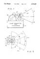
- FIG. 1is a schematic representation side view of the head-mounted projection display system illustrating a beam splitter for co-location;
- FIG. 2is a schematic representation top view of inset images projected from a head-mounted projection display system and having unlimited binocular overlap;
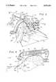
- FIG. 3is an orthogonal view of the head-mounted projection display system hereof;
- FIG. 4is an offset vertical cross-sectional view taken vertically through the head-mounted display system of FIG. 3;
- FIG. 5is an additional embodiment, a schematic representation top view of an image projected for the head-mounted projection display system having limited binocular overlap.
- the head-mounted projection display system featuring a beam splitter in accordance with the present inventionmay be embodied in a wide variety of forms, some of which may be quite different from those of the disclosed embodiment, as shown by example in FIGS. 1 and 5.
- the head-mounted projection display systemincludes: a head-mounted projector, image generator and processor, a head position sensor, one or more beam splitters and a retro-reflective screen. Note that these elements of the system are well known individually and therefore are not disclosed in structural detail.
- the head-mounted projectorsreceive identical inset and background images from a projector source that is connected to receive signals for a dynamic image generated by the image processor. Accordingly, the projector reduces the display signals to a pair of binocular images and projects these images, while a processor evaluates feedback from a head position sensor and compensates for angular head position changes made by the observer.
- the projected binocular imagesare partially reflected from the beam splitter toward a retro-reflective screen.
- the retro-reflective screenreflects back the co-located images directly into the observer's eyes, through the beam splitter.
- FIG. 1is a schematic representation side view of the head-mounted projection display system 20 featuring the beam splitter 30 and serving to illustrate a co-location arrangement for the projected images and the viewer's eyes.
- the head-mounted projection display system 20can be easily mounted onto a helmet, or other head mount not shown here.
- a head-mounted projector apparatus 21incorporates a cathode ray tube 36 as an illustrative image source that projects binocular light beams 34 produced by the image generator and processor 22.
- the light beams indicated generally at 34 in the form of a 5 mm cone of lightare focused through lens 36 into a point of light striking a beam splitter 30 which functions as a selectively reflecting surface transmitting approximately fifty percent of the reflected light beam 34' to a retro-reflective screen 32.
- a normal reflective screenwill not return much of the projected image to the eye.
- Fifty percent of the light energy of an exemplary beam 34is lost by the beam splitter 30, here.
- the light beam 34'bounces back through the beam splitter 30 into the observer's eye 27 as an image beam 34".
- the return reflected image beam 34"is fifty percent of the beam 34' reflected.
- the screen-reflected image beam 34"appears to the observer 26 as an image projected within the observer's eyes 27 and 27'.
- the observer 26 wearing the head-mounted projection display system 20sees the light beam 34' striking the screen 32 and the resultant image beam 34" striking his eye 27. Another observer not wearing the head-mounted apparatus 21 will not see the images.
- the observer 26can move his eye 27 within a 1/2" range, for example, up, down, left or right and still see the image beam 34", because each image beam 34" is projected directly onto the observer's pupil 28.
- the image beam 34"is approximately twenty-five percent of the generated light beam 34.
- the image beams 34"will appear to the observer 26 to move with his linear head motion exactly as if there were an infinite distance separating the projected images from the observer 26. The illusion is maintained during image simulation of an infinite distance between the observer 26 and the projected image, while the observer's eye 27 is focusing on the image on the retro-reflective screen 32.
- angular head motion by the observer 26must be compensated.
- the head position sensor 24controls the image generator and processor 22, determining where detail within the image beam 34" must move to provide correct perspective within the infinite viewing distance for the observer 26.
- feedback signalsare provided through a line 25 from the head position sensor 24 for processing in the image generator and processor 22.
- Angular motion compensationis received by the head-mounted projection apparatus 21 through data bus 48.
- the data bus 48is a wire.
- each of the image beams 34, 34' and 34"carry one of a pair of binocular images.
- the two sets of beamsare shown more clearly in FIG. 2, also see FIGS. 3 and 4.
- the image beam 34"'represents the 50 percent of the image beam 34 lost through the selectively transmissive beam splitter 30.
- FIG. 2is a schematic representation top view of an image projected from a head-mounted projection display system having unlimited binocular overlap. Some elements are not shown so as to illustrate the beam paths.
- the single beam splitter concept as shown in top view FIG. 2uses two image generators, here cathode ray tubes 37 and 37' (CRT) to obtain these fields of view.
- CRTcathode ray tubes
- the image projected from CRT 37enters background optical relay 33 and is split into two images by combining optics 100.
- These two identical imagesare projected simultaneously downward by mirrors 103 (FIGS. 3 and 4) and the two projection lenses 36, 36' from the beam splitter 30 toward flat or curved retro-reflective screen 32.
- These two identical images 34, 34'co-located with the viewers eyes, impinge the screen 32 and are returned from the retro-reflective screen to each eye 27, 27'.
- the beams 34 and 34'each carry a background portion and an inset portion and are formed by the optics 100 to be projected downwardly on the beam splitter 30 for a co-location projection to the screen 32.
- mirrors 10A, 10B, 10C and 10Doperate with a beam splitter 10X to combine inset and background images as two co-located beams 34 and 34'.
- inset imagefrom CRT 37'
- the background imagefrom CRT 37
- the inset imageis aligned within the background image in both two separate beams for co-location with the eyes and projected to the screen 32.
- the wide field of view (background) imageis projected at a range of approximately 120° to 140° horizontally. However, it is of low resolution, for example approximately 8 arc minutes of resolution.
- the other projector, CRT 37'also projects an inset narrow field of view of for example approximately 40° to both eyes 27, 27' providing images having high resolution, of approximately 2 arc minutes.
- the use of background and inset opticsproduces an image display to the observer 26 that have both wide field supporting his peripheral vision and high resolution at the center of the image display. This high resolution area is commonly called the observer's "area of interest" or inset region while the observer's wider field of view is referred to as his background region.
- cathode ray tube 37, 37'each project to both the observer's right and left eyes 27 and 27', respectively.
- cathode ray tube 37'projects narrow field, high resolution light beams 66, 66' to both of the observer's pupils 28, 28' through a single beam splitter 30.
- cathode ray tube 37projects a wide field light beam 64, 64' through beam splitter 30 to both the observer's eyes 27, 27'.
- the observer 26views the image beams 64, 64', 66 and 66' as left background image (LB), right background image (RB), left inset image (LI) and right inset image (RI), respectively.
- LBleft background image
- RBright background image
- LIleft inset image
- RIright inset image
- FIG. 3is an orthogonal partial view of the head-mounted projection display system 20.
- the observer 26wears the head-mounted projection display system 20 shown here on support mounting band 70.
- the observer's eyes 27 and 27'view the screen (not shown here) through the beam splitter 30 which is held by a beam splitter support bracket 74.
- Projection lens' 36, 36'are positioned above the beam splitter 30 along with mirrors 103.
- Cathode ray tube covers 72, 72'are mounted to the support mounting band 70.
- Display signalsare received by the cathode ray tubes (not shown here) housed within the cathode ray tubes covers 72, 72' through electrical wires 48, 48'.
- Counter weights 71counter balance the weight of the beam splitter 30 and projection lenses 36 and 36' facilitating the position of the head-mounted projection display system 20 on the head of observer 26.
- FIG. 4is an offset vertical cross section view taken through the head-mounted projection display system of FIG. 3.
- the head-mounted display system 20 with unlimited binocular overlapprojects an image 34" to the pupil 28 of the observer's eye 27
- a flat screen 32' shown in this examplereflects through beam splitter 30 into the observer's left pupil 28 the light beam 34 emitted from lens 36 and cathode ray tube 37 through an optical relay 33.
- the light beam 34'is selectively reflected through the beam splitter 30 where fifty percent of the light energy 34"' is lost.
- the imageis viewed by the observer from screen 32' as image beam 34".
- the left cathode ray tube cover 72contains the cathode ray tube 37, optical relay 33, a series of lens or a fiber optic bundle coupling half of the output from the cathode ray tube 37 to lens 36 mounted on the observer's head. One half of the light from the CRT is coupled to the other projection lens 36'.
- This head-mounted projection display systemoffers the best advantages of projection dome displays, such as large field of view, good eye relief, good pupil size and full binocular view plus the low cost and small size of the helmet-mounted direct view display.
- FIG. 5An alternative embodiment of the head-mounted projection system 20' is shown in FIG. 5.
- This system 20'requires a separate projection cathode ray tube for each eye 27, 27' because dual beam splitters 30, 30' either one piece or two pieces are positioned at different angles over each eye.
- the beam splitters 30, 30'would be positioned inclined in the vertical plane at 45° while inclined in the horizontal plane 90° to the observer's eyes. These angles are approximate in nature and can vary in a range of 10° plus or minus.
- the combining optics of the system described in detail by FIGS. 1, 2, 3 and 4are eliminated from this design.
- the embodiment of FIG. 5has the advantage of providing unlimited field of view (A+B) with limited binocular overlap (C).
- the head-mounted projection display system 20' of FIG. 5has a vertical field of view theoretically limited by the beam splitters 30, 30' to 90°. Images as electrical signals enter the projectors 37, 37' through electrical wires 48, 48'. Image beams 62 and 60 are emitted from projection lenses 36, 36' respectively. The image beams 60, 62 impinge the retro-reflective screen 32, shown covered in this example.
- the observer 26, with his right eye 27 and left eye 27'views a right eye field of view A and a left eye field view of B, respectively, reflected from flat or curved retro-reflective screen 32. Binocular overlap region C is the region viewed by observer 26 where A and B overlap.
- the optical co-location of the projectors for the observer's pupils 28, 28'provides the observer 26 with a wider field of view.
- the horizontal field of viewis still limited to 120° to 140°. This horizontal field limitation can be eliminated through the alternative embodiment shown in FIG. 5, however, full binocular coverage for the observer suffers.
- head-mounted projection display systemAnother advantage is the head-mounted projection display system's insensitivity to screen surface imperfections. These imperfections which traditionally occur in different areas of the two pictures projected upon the screen are thus ignored by the observer's brain. Consequently an expensive, continuous, high quality dome surface is not required as with conventional wide field of view projection simulator displays. Simple, flat panel screen surfaces are adequate to provide wide field of view projection simulation. For example, a basic one frequency icosahedron, provides unlimited field of view capability for the described head-mounted projection display system.
- the head-mounted projection display system described hereinhas been directed toward flight simulators and the like. However, it is not outside the scope of the disclosed projection system to be employed in any environmental simulation including, but not limited to; video games, land based vehicles, motion pictures or any other video graphic displays.
Landscapes
- Physics & Mathematics (AREA)
- Engineering & Computer Science (AREA)
- General Physics & Mathematics (AREA)
- Optics & Photonics (AREA)
- Theoretical Computer Science (AREA)
- Aviation & Aerospace Engineering (AREA)
- Business, Economics & Management (AREA)
- Educational Administration (AREA)
- Educational Technology (AREA)
- Testing, Inspecting, Measuring Of Stereoscopic Televisions And Televisions (AREA)
- Instrument Panels (AREA)
Abstract
Description
Claims (14)
Priority Applications (1)
| Application Number | Priority Date | Filing Date | Title |
|---|---|---|---|
| US08/144,169US5572229A (en) | 1991-04-22 | 1993-10-26 | Head-mounted projection display system featuring beam splitter and method of making same |
Applications Claiming Priority (2)
| Application Number | Priority Date | Filing Date | Title |
|---|---|---|---|
| US69017391A | 1991-04-22 | 1991-04-22 | |
| US08/144,169US5572229A (en) | 1991-04-22 | 1993-10-26 | Head-mounted projection display system featuring beam splitter and method of making same |
Related Parent Applications (1)
| Application Number | Title | Priority Date | Filing Date |
|---|---|---|---|
| US69017391AContinuation-In-Part | 1991-04-22 | 1991-04-22 |
Publications (1)
| Publication Number | Publication Date |
|---|---|
| US5572229Atrue US5572229A (en) | 1996-11-05 |
Family
ID=24771395
Family Applications (1)
| Application Number | Title | Priority Date | Filing Date |
|---|---|---|---|
| US08/144,169Expired - LifetimeUS5572229A (en) | 1991-04-22 | 1993-10-26 | Head-mounted projection display system featuring beam splitter and method of making same |
Country Status (7)
| Country | Link |
|---|---|
| US (1) | US5572229A (en) |
| JP (1) | JPH06502054A (en) |
| CA (1) | CA2085735A1 (en) |
| DE (1) | DE4291016T1 (en) |
| FR (1) | FR2675613A1 (en) |
| GB (1) | GB2261804A (en) |
| WO (1) | WO1992018971A1 (en) |
Cited By (135)
| Publication number | Priority date | Publication date | Assignee | Title |
|---|---|---|---|---|
| WO1997034411A1 (en)* | 1996-03-13 | 1997-09-18 | Fraser-Volpe Corporation | Real-time, multiple path video imaging system |
| US5726806A (en)* | 1994-08-05 | 1998-03-10 | Central Research Laboratories Limited | Apparatus for displaying a plurality of viewable images of an object |
| US5726671A (en)* | 1996-10-07 | 1998-03-10 | Hughes Electronics | Helmet/head mounted projector system |
| WO1998058357A1 (en)* | 1997-06-13 | 1998-12-23 | SOFTWINGS Société Anonyme | Flight simulator |
| US5864431A (en)* | 1997-07-07 | 1999-01-26 | Redifun Stimulation, Inc. | Method and apparatus for elimination of distortion in rear projection to curved surfaces |
| US5912650A (en)* | 1996-10-16 | 1999-06-15 | Kaiser Electro-Optics, Inc. | Dichoptic display utilizing a single display device |
| US6008945A (en)* | 1996-09-19 | 1999-12-28 | Fergason; James L. | Display system using conjugate optics and accommodation features and method of displaying and viewing an image |
| US6147805A (en)* | 1994-08-24 | 2000-11-14 | Fergason; James L. | Head mounted display and viewing system using a remote retro-reflector and method of displaying and viewing an image |
| US6222675B1 (en) | 1998-12-01 | 2001-04-24 | Kaiser Electro-Optics, Inc. | Area of interest head-mounted display using low resolution, wide angle; high resolution, narrow angle; and see-through views |
| US6379009B1 (en) | 1996-04-24 | 2002-04-30 | James L. Fergason | Conjugate optics projection display with image enhancement |
| US6416181B1 (en) | 2000-12-15 | 2002-07-09 | Eastman Kodak Company | Monocentric autostereoscopic optical apparatus and method |
| US20020196554A1 (en)* | 2001-06-11 | 2002-12-26 | Eastman Kodak Company | Head-mounted optical apparatus for stereoscopic display |
| US6511182B1 (en) | 2001-11-13 | 2003-01-28 | Eastman Kodak Company | Autostereoscopic optical apparatus using a scanned linear image source |
| US6550918B1 (en) | 2002-03-19 | 2003-04-22 | Eastman Kodak Company | Monocentric autostereoscopic viewing apparatus using resonant fiber-optic image generation |
| US20030129567A1 (en)* | 2001-11-29 | 2003-07-10 | Lsa, Inc. | Periscopic optical in-situ training system and method for using the same |
| US6609802B1 (en)* | 1999-09-23 | 2003-08-26 | Majax Gerard | Optical instrument with upward viewing in a horizontal mirror |
| US20030169405A1 (en)* | 2002-03-08 | 2003-09-11 | Eastman Kodak Company | Monocentric autostereoscopic optical apparatus using resonant fiber-optic image generation |
| US6671100B1 (en) | 1999-10-14 | 2003-12-30 | Stratos Product Development Llc | Virtual imaging system |
| US20040017546A1 (en)* | 2002-07-26 | 2004-01-29 | Eastman Kodak Company | Monocentric autostereoscopic optical display having an expanded color gamut |
| US20040068912A1 (en)* | 2000-12-21 | 2004-04-15 | Per Renntoft | Device a use and a method for tracer stream simulation |
| US6724353B2 (en)* | 2000-08-08 | 2004-04-20 | Koninklijke Philips Electronics N.V. | Display device |
| US6752498B2 (en) | 2001-05-14 | 2004-06-22 | Eastman Kodak Company | Adaptive autostereoscopic display system |
| US6768585B2 (en) | 2002-05-02 | 2004-07-27 | Eastman Kodak Company | Monocentric autostereoscopic optical apparatus using a scanned linear electromechanical modulator |
| US6774869B2 (en) | 2000-12-22 | 2004-08-10 | Board Of Trustees Operating Michigan State University | Teleportal face-to-face system |
| US20040162637A1 (en)* | 2002-07-25 | 2004-08-19 | Yulun Wang | Medical tele-robotic system with a master remote station with an arbitrator |
| US20040174129A1 (en)* | 2003-03-06 | 2004-09-09 | Yulun Wang | Medical tele-robotic system with a head worn device |
| US20040212882A1 (en)* | 2003-04-22 | 2004-10-28 | Eastman Kodak Company | Monocentric autostereoscopic optical apparatus with a spherical gradient-index ball lens |
| US6963454B1 (en) | 2002-03-01 | 2005-11-08 | Research Foundation Of The University Of Central Florida | Head-mounted display by integration of phase-conjugate material |
| US20060017654A1 (en)* | 2004-07-23 | 2006-01-26 | Romo Justin R | Virtual reality interactivity system and method |
| US6999239B1 (en) | 2001-05-23 | 2006-02-14 | Research Foundation Of The University Of Central Florida, Inc | Head-mounted display by integration of phase-conjugate material |
| US20060082642A1 (en)* | 2002-07-25 | 2006-04-20 | Yulun Wang | Tele-robotic videoconferencing in a corporate environment |
| US7119965B1 (en)* | 2003-02-24 | 2006-10-10 | University Of Central Florida Research Foundation, Inc. | Head mounted projection display with a wide field of view |
| US20060259193A1 (en)* | 2005-05-12 | 2006-11-16 | Yulun Wang | Telerobotic system with a dual application screen presentation |
| US7158861B2 (en) | 2002-07-25 | 2007-01-02 | Intouch Technologies, Inc. | Tele-robotic system used to provide remote consultation services |
| US7190392B1 (en)* | 1997-10-23 | 2007-03-13 | Maguire Jr Francis J | Telepresence system and active/passive mode display for use therein |
| US20070064311A1 (en)* | 2005-08-05 | 2007-03-22 | Park Brian V | Head mounted projector display for flat and immersive media |
| US20070285663A1 (en)* | 2006-06-12 | 2007-12-13 | The Boeing Company | Efficient and accurate alignment of stereoscopic displays |
| US20070285774A1 (en)* | 2006-06-12 | 2007-12-13 | The Boeing Company | Augmenting brightness performance of a beam-splitter in a stereoscopic display |
| US20080002262A1 (en)* | 2006-06-29 | 2008-01-03 | Anthony Chirieleison | Eye tracking head mounted display |
| US20080082211A1 (en)* | 2006-10-03 | 2008-04-03 | Yulun Wang | Remote presence display through remotely controlled robot |
| US7522344B1 (en) | 2005-12-14 | 2009-04-21 | University Of Central Florida Research Foundation, Inc. | Projection-based head-mounted display with eye-tracking capabilities |
| US20090225001A1 (en)* | 2007-11-06 | 2009-09-10 | University Of Central Florida Research Foundation, Inc. | Hybrid Display Systems and Methods |
| US20100001928A1 (en)* | 2008-06-30 | 2010-01-07 | Honeywell International Inc. | Head-mountable cockpit display system |
| US20100115418A1 (en)* | 2004-02-26 | 2010-05-06 | Yulun Wang | Graphical interface for a remote presence system |
| US7769492B2 (en) | 2006-02-22 | 2010-08-03 | Intouch Technologies, Inc. | Graphical interface for a remote presence system |
| US7813836B2 (en) | 2003-12-09 | 2010-10-12 | Intouch Technologies, Inc. | Protocol for a remotely controlled videoconferencing robot |
| US20110037951A1 (en)* | 2008-01-22 | 2011-02-17 | Hong Hua | Head-mounted projection display using reflective microdisplays |
| US7891818B2 (en) | 2006-12-12 | 2011-02-22 | Evans & Sutherland Computer Corporation | System and method for aligning RGB light in a single modulator projector |
| WO2011042503A1 (en) | 2009-10-07 | 2011-04-14 | York Winter | Arrangement and method for visually representing scenes, corresponding computer program and corresponding computer-readable storage medium |
| US20110221671A1 (en)* | 2010-02-28 | 2011-09-15 | Osterhout Group, Inc. | Method and apparatus for audio biometric data capture |
| US8077963B2 (en) | 2004-07-13 | 2011-12-13 | Yulun Wang | Mobile robot with a head-based movement mapping scheme |
| US8077378B1 (en) | 2008-11-12 | 2011-12-13 | Evans & Sutherland Computer Corporation | Calibration system and method for light modulation device |
| US8116910B2 (en) | 2007-08-23 | 2012-02-14 | Intouch Technologies, Inc. | Telepresence robot with a printer |
| US8170241B2 (en) | 2008-04-17 | 2012-05-01 | Intouch Technologies, Inc. | Mobile tele-presence system with a microphone system |
| US8179418B2 (en) | 2008-04-14 | 2012-05-15 | Intouch Technologies, Inc. | Robotic based health care system |
| US8340819B2 (en) | 2008-09-18 | 2012-12-25 | Intouch Technologies, Inc. | Mobile videoconferencing robot system with network adaptive driving |
| US8358317B2 (en) | 2008-05-23 | 2013-01-22 | Evans & Sutherland Computer Corporation | System and method for displaying a planar image on a curved surface |
| US8384755B2 (en) | 2009-08-26 | 2013-02-26 | Intouch Technologies, Inc. | Portable remote presence robot |
| US8463435B2 (en) | 2008-11-25 | 2013-06-11 | Intouch Technologies, Inc. | Server connectivity control for tele-presence robot |
| US8467133B2 (en) | 2010-02-28 | 2013-06-18 | Osterhout Group, Inc. | See-through display with an optical assembly including a wedge-shaped illumination system |
| US8472120B2 (en) | 2010-02-28 | 2013-06-25 | Osterhout Group, Inc. | See-through near-eye display glasses with a small scale image source |
| US8477425B2 (en) | 2010-02-28 | 2013-07-02 | Osterhout Group, Inc. | See-through near-eye display glasses including a partially reflective, partially transmitting optical element |
| US8482859B2 (en) | 2010-02-28 | 2013-07-09 | Osterhout Group, Inc. | See-through near-eye display glasses wherein image light is transmitted to and reflected from an optically flat film |
| US8488246B2 (en) | 2010-02-28 | 2013-07-16 | Osterhout Group, Inc. | See-through near-eye display glasses including a curved polarizing film in the image source, a partially reflective, partially transmitting optical element and an optically flat film |
| US8670017B2 (en) | 2010-03-04 | 2014-03-11 | Intouch Technologies, Inc. | Remote presence system including a cart that supports a robot face and an overhead camera |
| US8702248B1 (en) | 2008-06-11 | 2014-04-22 | Evans & Sutherland Computer Corporation | Projection method for reducing interpixel gaps on a viewing surface |
| US8718837B2 (en) | 2011-01-28 | 2014-05-06 | Intouch Technologies | Interfacing with a mobile telepresence robot |
| US8836751B2 (en) | 2011-11-08 | 2014-09-16 | Intouch Technologies, Inc. | Tele-presence system with a user interface that displays different communication links |
| US8849679B2 (en) | 2006-06-15 | 2014-09-30 | Intouch Technologies, Inc. | Remote controlled robot system that provides medical images |
| US8849680B2 (en) | 2009-01-29 | 2014-09-30 | Intouch Technologies, Inc. | Documentation through a remote presence robot |
| US8892260B2 (en) | 2007-03-20 | 2014-11-18 | Irobot Corporation | Mobile robot for telecommunication |
| US8897920B2 (en) | 2009-04-17 | 2014-11-25 | Intouch Technologies, Inc. | Tele-presence robot system with software modularity, projector and laser pointer |
| US8902278B2 (en) | 2012-04-11 | 2014-12-02 | Intouch Technologies, Inc. | Systems and methods for visualizing and managing telepresence devices in healthcare networks |
| US8930019B2 (en) | 2010-12-30 | 2015-01-06 | Irobot Corporation | Mobile human interface robot |
| US8935005B2 (en) | 2010-05-20 | 2015-01-13 | Irobot Corporation | Operating a mobile robot |
| US8996165B2 (en) | 2008-10-21 | 2015-03-31 | Intouch Technologies, Inc. | Telepresence robot with a camera boom |
| US9014848B2 (en) | 2010-05-20 | 2015-04-21 | Irobot Corporation | Mobile robot system |
| US9091851B2 (en) | 2010-02-28 | 2015-07-28 | Microsoft Technology Licensing, Llc | Light control in head mounted displays |
| US9097891B2 (en) | 2010-02-28 | 2015-08-04 | Microsoft Technology Licensing, Llc | See-through near-eye display glasses including an auto-brightness control for the display brightness based on the brightness in the environment |
| US9098611B2 (en) | 2012-11-26 | 2015-08-04 | Intouch Technologies, Inc. | Enhanced video interaction for a user interface of a telepresence network |
| US9097890B2 (en) | 2010-02-28 | 2015-08-04 | Microsoft Technology Licensing, Llc | Grating in a light transmissive illumination system for see-through near-eye display glasses |
| US9128281B2 (en) | 2010-09-14 | 2015-09-08 | Microsoft Technology Licensing, Llc | Eyepiece with uniformly illuminated reflective display |
| US9129295B2 (en) | 2010-02-28 | 2015-09-08 | Microsoft Technology Licensing, Llc | See-through near-eye display glasses with a fast response photochromic film system for quick transition from dark to clear |
| US9134534B2 (en) | 2010-02-28 | 2015-09-15 | Microsoft Technology Licensing, Llc | See-through near-eye display glasses including a modular image source |
| US9138891B2 (en) | 2008-11-25 | 2015-09-22 | Intouch Technologies, Inc. | Server connectivity control for tele-presence robot |
| US9160783B2 (en) | 2007-05-09 | 2015-10-13 | Intouch Technologies, Inc. | Robot system that operates through a network firewall |
| US9174342B2 (en) | 2012-05-22 | 2015-11-03 | Intouch Technologies, Inc. | Social behavior rules for a medical telepresence robot |
| US9182596B2 (en) | 2010-02-28 | 2015-11-10 | Microsoft Technology Licensing, Llc | See-through near-eye display glasses with the optical assembly including absorptive polarizers or anti-reflective coatings to reduce stray light |
| US9193065B2 (en) | 2008-07-10 | 2015-11-24 | Intouch Technologies, Inc. | Docking system for a tele-presence robot |
| US9198728B2 (en) | 2005-09-30 | 2015-12-01 | Intouch Technologies, Inc. | Multi-camera mobile teleconferencing platform |
| US9223134B2 (en) | 2010-02-28 | 2015-12-29 | Microsoft Technology Licensing, Llc | Optical imperfections in a light transmissive illumination system for see-through near-eye display glasses |
| US9229227B2 (en) | 2010-02-28 | 2016-01-05 | Microsoft Technology Licensing, Llc | See-through near-eye display glasses with a light transmissive wedge shaped illumination system |
| US9239453B2 (en) | 2009-04-20 | 2016-01-19 | Beijing Institute Of Technology | Optical see-through free-form head-mounted display |
| US9244339B2 (en) | 2012-06-15 | 2016-01-26 | Mirraviz, Inc. | Systems and methods for displaying an image or video on a retro-reflective screen |
| US9244277B2 (en) | 2010-04-30 | 2016-01-26 | The Arizona Board Of Regents On Behalf Of The University Of Arizona | Wide angle and high resolution tiled head-mounted display device |
| US9251313B2 (en) | 2012-04-11 | 2016-02-02 | Intouch Technologies, Inc. | Systems and methods for visualizing and managing telepresence devices in healthcare networks |
| US9264664B2 (en) | 2010-12-03 | 2016-02-16 | Intouch Technologies, Inc. | Systems and methods for dynamic bandwidth allocation |
| US9285589B2 (en) | 2010-02-28 | 2016-03-15 | Microsoft Technology Licensing, Llc | AR glasses with event and sensor triggered control of AR eyepiece applications |
| US9323250B2 (en) | 2011-01-28 | 2016-04-26 | Intouch Technologies, Inc. | Time-dependent navigation of telepresence robots |
| US9341843B2 (en) | 2010-02-28 | 2016-05-17 | Microsoft Technology Licensing, Llc | See-through near-eye display glasses with a small scale image source |
| US9361021B2 (en) | 2012-05-22 | 2016-06-07 | Irobot Corporation | Graphical user interfaces including touchpad driving interfaces for telemedicine devices |
| US9366862B2 (en) | 2010-02-28 | 2016-06-14 | Microsoft Technology Licensing, Llc | System and method for delivering content to a group of see-through near eye display eyepieces |
| US9498886B2 (en) | 2010-05-20 | 2016-11-22 | Irobot Corporation | Mobile human interface robot |
| US9641826B1 (en) | 2011-10-06 | 2017-05-02 | Evans & Sutherland Computer Corporation | System and method for displaying distant 3-D stereo on a dome surface |
| US9720232B2 (en) | 2012-01-24 | 2017-08-01 | The Arizona Board Of Regents On Behalf Of The University Of Arizona | Compact eye-tracked head-mounted display |
| US9720233B2 (en) | 2014-11-07 | 2017-08-01 | Honeywell International Inc. | Compact proximity display utilizing image transfer |
| US9759917B2 (en) | 2010-02-28 | 2017-09-12 | Microsoft Technology Licensing, Llc | AR glasses with event and sensor triggered AR eyepiece interface to external devices |
| US9810975B2 (en) | 2015-02-11 | 2017-11-07 | University Of Denver | Rear-projected life-like robotic head |
| US9842192B2 (en) | 2008-07-11 | 2017-12-12 | Intouch Technologies, Inc. | Tele-presence robot system with multi-cast features |
| US9874760B2 (en) | 2012-10-18 | 2018-01-23 | Arizona Board Of Regents On Behalf Of The University Of Arizona | Stereoscopic displays with addressable focus cues |
| US9974612B2 (en) | 2011-05-19 | 2018-05-22 | Intouch Technologies, Inc. | Enhanced diagnostics for a telepresence robot |
| US10139644B2 (en) | 2016-07-01 | 2018-11-27 | Tilt Five, Inc | Head mounted projection display with multilayer beam splitter and color correction |
| US10176961B2 (en) | 2015-02-09 | 2019-01-08 | The Arizona Board Of Regents On Behalf Of The University Of Arizona | Small portable night vision system |
| US10180572B2 (en) | 2010-02-28 | 2019-01-15 | Microsoft Technology Licensing, Llc | AR glasses with event and user action control of external applications |
| US10343283B2 (en) | 2010-05-24 | 2019-07-09 | Intouch Technologies, Inc. | Telepresence robot system that can be accessed by a cellular phone |
| US10539787B2 (en) | 2010-02-28 | 2020-01-21 | Microsoft Technology Licensing, Llc | Head-worn adaptive display |
| USD885453S1 (en)* | 2018-07-06 | 2020-05-26 | Furhat Robotics Ab | Industrial robot |
| US10739578B2 (en) | 2016-08-12 | 2020-08-11 | The Arizona Board Of Regents On Behalf Of The University Of Arizona | High-resolution freeform eyepiece design with a large exit pupil |
| US10769739B2 (en) | 2011-04-25 | 2020-09-08 | Intouch Technologies, Inc. | Systems and methods for management of information among medical providers and facilities |
| US10805598B2 (en) | 2014-03-05 | 2020-10-13 | The Arizona Board Of Regents On Behalf Of The University Of Arizona | Wearable 3D lightfield augmented reality display |
| US10808882B2 (en) | 2010-05-26 | 2020-10-20 | Intouch Technologies, Inc. | Tele-robotic system with a robot face placed on a chair |
| US10860100B2 (en) | 2010-02-28 | 2020-12-08 | Microsoft Technology Licensing, Llc | AR glasses with predictive control of external device based on event input |
| US10875182B2 (en) | 2008-03-20 | 2020-12-29 | Teladoc Health, Inc. | Remote presence system mounted to operating room hardware |
| US11079596B2 (en) | 2009-09-14 | 2021-08-03 | The Arizona Board Of Regents On Behalf Of The University Of Arizona | 3-dimensional electro-optical see-through displays |
| US11154981B2 (en) | 2010-02-04 | 2021-10-26 | Teladoc Health, Inc. | Robot user interface for telepresence robot system |
| US11389064B2 (en) | 2018-04-27 | 2022-07-19 | Teladoc Health, Inc. | Telehealth cart that supports a removable tablet with seamless audio/video switching |
| US11399153B2 (en) | 2009-08-26 | 2022-07-26 | Teladoc Health, Inc. | Portable telepresence apparatus |
| US11546575B2 (en) | 2018-03-22 | 2023-01-03 | Arizona Board Of Regents On Behalf Of The University Of Arizona | Methods of rendering light field images for integral-imaging-based light field display |
| US11636944B2 (en) | 2017-08-25 | 2023-04-25 | Teladoc Health, Inc. | Connectivity infrastructure for a telehealth platform |
| US11742094B2 (en) | 2017-07-25 | 2023-08-29 | Teladoc Health, Inc. | Modular telehealth cart with thermal imaging and touch screen user interface |
| US11862302B2 (en) | 2017-04-24 | 2024-01-02 | Teladoc Health, Inc. | Automated transcription and documentation of tele-health encounters |
| US12044850B2 (en) | 2017-03-09 | 2024-07-23 | Arizona Board Of Regents On Behalf Of The University Of Arizona | Head-mounted light field display with integral imaging and waveguide prism |
| US12078802B2 (en) | 2017-03-09 | 2024-09-03 | Arizona Board Of Regents On Behalf Of The University Of Arizona | Head-mounted light field display with integral imaging and relay optics |
| US12093036B2 (en) | 2011-01-21 | 2024-09-17 | Teladoc Health, Inc. | Telerobotic system with a dual application screen presentation |
| US12224059B2 (en) | 2011-02-16 | 2025-02-11 | Teladoc Health, Inc. | Systems and methods for network-based counseling |
Families Citing this family (28)
| Publication number | Priority date | Publication date | Assignee | Title |
|---|---|---|---|---|
| US5606458A (en)* | 1994-08-24 | 1997-02-25 | Fergason; James L. | Head mounted display and viewing system using a remote retro-reflector and method of displaying and viewing an image |
| US5621572A (en)* | 1994-08-24 | 1997-04-15 | Fergason; James L. | Optical system for a head mounted display using a retro-reflector and method of displaying an image |
| US5808802A (en)* | 1996-11-15 | 1998-09-15 | Daewoo Electronics Co. Ltd. | Head-mounted display apparatus with a single image display device |
| US5751493A (en)* | 1996-11-15 | 1998-05-12 | Daewoo Electronics Co., Ltd. | Head-mounted display apparatus with a single image display device |
| RU2128860C1 (en)* | 1997-03-04 | 1999-04-10 | Летно-исследовательский институт им.М.М.Громова | Device for simulation of visual orientation of pilot |
| FR2764997B1 (en)* | 1997-06-20 | 1999-09-03 | Sextant Avionique | VISUALIZATION DEVICE FOR HELMET VISUAL |
| DE19731303B4 (en)* | 1997-07-13 | 2009-02-26 | Smi Senso Motoric Instruments Gmbh | Method and device for contactless, helmet-free measurement of the direction of view of eyes during head and eye movements |
| JP3900446B2 (en)* | 1998-06-19 | 2007-04-04 | 株式会社東京大学Tlo | Image display method and apparatus |
| DE19836002B4 (en)* | 1998-08-08 | 2010-02-11 | Eurocopter Deutschland Gmbh | Stereoscopic flight guidance |
| RU2152079C1 (en)* | 1998-10-12 | 2000-06-27 | Донской филиал Центра тренажеростроения | Compact device for separate visualization of peripheral vision region and clear vision region in training set |
| US6535182B2 (en)* | 1998-12-07 | 2003-03-18 | Koninklijke Philips Electronics N.V. | Head-mounted projection display system |
| GB2370818B (en) | 2001-01-03 | 2004-01-14 | Seos Displays Ltd | A simulator |
| FR2845165B1 (en) | 2002-09-26 | 2004-12-24 | Arvinmeritor Light Vehicle Sys | OBSTACLE DETECTOR FOR A VEHICLE OPENING ELEMENT |
| EP2208354A4 (en) | 2007-10-10 | 2010-12-22 | Gerard Dirk Smits | Image projector with reflected light tracking |
| US9946076B2 (en) | 2010-10-04 | 2018-04-17 | Gerard Dirk Smits | System and method for 3-D projection and enhancements for interactivity |
| US8971568B1 (en) | 2012-10-08 | 2015-03-03 | Gerard Dirk Smits | Method, apparatus, and manufacture for document writing and annotation with virtual ink |
| US9810913B2 (en) | 2014-03-28 | 2017-11-07 | Gerard Dirk Smits | Smart head-mounted projection system |
| WO2016025502A1 (en) | 2014-08-11 | 2016-02-18 | Gerard Dirk Smits | Three-dimensional triangulation and time-of-flight based tracking systems and methods |
| US10404975B2 (en) | 2015-03-20 | 2019-09-03 | Tilt Five, Inc | Retroreflective light field display |
| US10043282B2 (en) | 2015-04-13 | 2018-08-07 | Gerard Dirk Smits | Machine vision for ego-motion, segmenting, and classifying objects |
| JP6854828B2 (en) | 2015-12-18 | 2021-04-07 | ジェラルド ディルク スミッツ | Real-time position detection of an object |
| US9813673B2 (en) | 2016-01-20 | 2017-11-07 | Gerard Dirk Smits | Holographic video capture and telepresence system |
| WO2018106360A2 (en) | 2016-10-31 | 2018-06-14 | Gerard Dirk Smits | Fast scanning lidar with dynamic voxel probing |
| JP7329444B2 (en) | 2016-12-27 | 2023-08-18 | ジェラルド ディルク スミッツ | Systems and methods for machine perception |
| WO2018209096A2 (en) | 2017-05-10 | 2018-11-15 | Gerard Dirk Smits | Scan mirror systems and methods |
| WO2019079750A1 (en) | 2017-10-19 | 2019-04-25 | Gerard Dirk Smits | Methods and systems for navigating a vehicle including a novel fiducial marker system |
| US10379220B1 (en) | 2018-01-29 | 2019-08-13 | Gerard Dirk Smits | Hyper-resolved, high bandwidth scanned LIDAR systems |
| WO2021174227A1 (en) | 2020-02-27 | 2021-09-02 | Gerard Dirk Smits | High resolution scanning of remote objects with fast sweeping laser beams and signal recovery by twitchy pixel array |
Citations (24)
| Publication number | Priority date | Publication date | Assignee | Title |
|---|---|---|---|---|
| US3709581A (en)* | 1971-02-05 | 1973-01-09 | Singer Co | Wide angle infinity image visual display |
| US4016658A (en)* | 1971-04-02 | 1977-04-12 | Redifon Limited | Video ground-based flight simulation apparatus |
| US4028725A (en)* | 1976-04-21 | 1977-06-07 | Grumman Aerospace Corporation | High-resolution vision system |
| US4048653A (en)* | 1974-10-16 | 1977-09-13 | Redifon Limited | Visual display apparatus |
| US4119956A (en)* | 1975-06-30 | 1978-10-10 | Redifon Flight Simulation Limited | Raster-scan display apparatus for computer-generated images |
| US4303394A (en)* | 1980-07-10 | 1981-12-01 | The United States Of America As Represented By The Secretary Of The Navy | Computer generated image simulator |
| US4340878A (en)* | 1979-01-11 | 1982-07-20 | Redifon Simulation Limited | Visual display apparatus |
| US4343037A (en)* | 1979-06-15 | 1982-08-03 | Redifon Simulation Limited | Visual display systems of the computer generated image type |
| US4348186A (en)* | 1979-12-17 | 1982-09-07 | The United States Of America As Represented By The Secretary Of The Navy | Pilot helmet mounted CIG display with eye coupled area of interest |
| US4348185A (en)* | 1980-02-14 | 1982-09-07 | The United States Of America As Represented By The Secretary Of The Navy | Wide angle infinity display system |
| US4349815A (en)* | 1979-01-11 | 1982-09-14 | Redifon Simulation Limited | Head-movable frame-scanner for head-coupled display |
| US4437113A (en)* | 1981-12-21 | 1984-03-13 | The United States Of America As Represented By The Secretary Of The Air Force | Anti-flutter apparatus for head mounted visual display |
| US4439157A (en)* | 1982-05-03 | 1984-03-27 | The United States Of America As Represented By The Secretary Of The Navy | Helmet mounted display projector |
| US4446480A (en)* | 1981-12-14 | 1984-05-01 | The United States Of America As Represented By The Secretary Of The Navy | Head position and orientation sensor |
| US4634384A (en)* | 1984-02-02 | 1987-01-06 | General Electric Company | Head and/or eye tracked optically blended display system |
| US4657512A (en)* | 1985-06-08 | 1987-04-14 | The Singer Company | Visual system with filter for a simulator |
| US4714428A (en)* | 1985-12-19 | 1987-12-22 | General Electric Company | Method of comprehensive distortion correction for a computer image generation system |
| US4743200A (en)* | 1984-11-13 | 1988-05-10 | Cae Electronics, Ltd. | Fiber optic coupled helmet mounted display system |
| US4811245A (en)* | 1985-12-19 | 1989-03-07 | General Electric Company | Method of edge smoothing for a computer image generation system |
| US4897715A (en)* | 1988-10-31 | 1990-01-30 | General Electric Company | Helmet display |
| US4930888A (en)* | 1987-11-07 | 1990-06-05 | Messerschmitt-Boelkow-Blohm Gesellschaft Mit Beschraenkter Haftung | Situation display system for attachment to a headgear |
| US4969714A (en)* | 1989-02-21 | 1990-11-13 | United Technologies Corporation | Helmet mounted display having dual interchangeable optical eyepieces |
| US4994794A (en)* | 1987-06-29 | 1991-02-19 | Gec-Marconi Limited | Methods and apparatus for displaying data |
| US5124821A (en)* | 1987-03-31 | 1992-06-23 | Thomson Csf | Large-field holographic binocular helmet visor |
- 1992
- 1992-04-20DEDE4291016Tpatent/DE4291016T1/denot_activeWithdrawn
- 1992-04-20WOPCT/US1992/003226patent/WO1992018971A1/enactiveApplication Filing
- 1992-04-20JPJP4510312Apatent/JPH06502054A/enactivePending
- 1992-04-20CACA002085735Apatent/CA2085735A1/ennot_activeAbandoned
- 1992-04-21FRFR9204863Apatent/FR2675613A1/ennot_activeWithdrawn
- 1992-12-17GBGB9226364Apatent/GB2261804A/ennot_activeWithdrawn
- 1993
- 1993-10-26USUS08/144,169patent/US5572229A/ennot_activeExpired - Lifetime
Patent Citations (24)
| Publication number | Priority date | Publication date | Assignee | Title |
|---|---|---|---|---|
| US3709581A (en)* | 1971-02-05 | 1973-01-09 | Singer Co | Wide angle infinity image visual display |
| US4016658A (en)* | 1971-04-02 | 1977-04-12 | Redifon Limited | Video ground-based flight simulation apparatus |
| US4048653A (en)* | 1974-10-16 | 1977-09-13 | Redifon Limited | Visual display apparatus |
| US4119956A (en)* | 1975-06-30 | 1978-10-10 | Redifon Flight Simulation Limited | Raster-scan display apparatus for computer-generated images |
| US4028725A (en)* | 1976-04-21 | 1977-06-07 | Grumman Aerospace Corporation | High-resolution vision system |
| US4340878A (en)* | 1979-01-11 | 1982-07-20 | Redifon Simulation Limited | Visual display apparatus |
| US4349815A (en)* | 1979-01-11 | 1982-09-14 | Redifon Simulation Limited | Head-movable frame-scanner for head-coupled display |
| US4343037A (en)* | 1979-06-15 | 1982-08-03 | Redifon Simulation Limited | Visual display systems of the computer generated image type |
| US4348186A (en)* | 1979-12-17 | 1982-09-07 | The United States Of America As Represented By The Secretary Of The Navy | Pilot helmet mounted CIG display with eye coupled area of interest |
| US4348185A (en)* | 1980-02-14 | 1982-09-07 | The United States Of America As Represented By The Secretary Of The Navy | Wide angle infinity display system |
| US4303394A (en)* | 1980-07-10 | 1981-12-01 | The United States Of America As Represented By The Secretary Of The Navy | Computer generated image simulator |
| US4446480A (en)* | 1981-12-14 | 1984-05-01 | The United States Of America As Represented By The Secretary Of The Navy | Head position and orientation sensor |
| US4437113A (en)* | 1981-12-21 | 1984-03-13 | The United States Of America As Represented By The Secretary Of The Air Force | Anti-flutter apparatus for head mounted visual display |
| US4439157A (en)* | 1982-05-03 | 1984-03-27 | The United States Of America As Represented By The Secretary Of The Navy | Helmet mounted display projector |
| US4634384A (en)* | 1984-02-02 | 1987-01-06 | General Electric Company | Head and/or eye tracked optically blended display system |
| US4743200A (en)* | 1984-11-13 | 1988-05-10 | Cae Electronics, Ltd. | Fiber optic coupled helmet mounted display system |
| US4657512A (en)* | 1985-06-08 | 1987-04-14 | The Singer Company | Visual system with filter for a simulator |
| US4714428A (en)* | 1985-12-19 | 1987-12-22 | General Electric Company | Method of comprehensive distortion correction for a computer image generation system |
| US4811245A (en)* | 1985-12-19 | 1989-03-07 | General Electric Company | Method of edge smoothing for a computer image generation system |
| US5124821A (en)* | 1987-03-31 | 1992-06-23 | Thomson Csf | Large-field holographic binocular helmet visor |
| US4994794A (en)* | 1987-06-29 | 1991-02-19 | Gec-Marconi Limited | Methods and apparatus for displaying data |
| US4930888A (en)* | 1987-11-07 | 1990-06-05 | Messerschmitt-Boelkow-Blohm Gesellschaft Mit Beschraenkter Haftung | Situation display system for attachment to a headgear |
| US4897715A (en)* | 1988-10-31 | 1990-01-30 | General Electric Company | Helmet display |
| US4969714A (en)* | 1989-02-21 | 1990-11-13 | United Technologies Corporation | Helmet mounted display having dual interchangeable optical eyepieces |
Cited By (258)
| Publication number | Priority date | Publication date | Assignee | Title |
|---|---|---|---|---|
| US5726806A (en)* | 1994-08-05 | 1998-03-10 | Central Research Laboratories Limited | Apparatus for displaying a plurality of viewable images of an object |
| US6147805A (en)* | 1994-08-24 | 2000-11-14 | Fergason; James L. | Head mounted display and viewing system using a remote retro-reflector and method of displaying and viewing an image |
| WO1997034411A1 (en)* | 1996-03-13 | 1997-09-18 | Fraser-Volpe Corporation | Real-time, multiple path video imaging system |
| US6379009B1 (en) | 1996-04-24 | 2002-04-30 | James L. Fergason | Conjugate optics projection display with image enhancement |
| US6008945A (en)* | 1996-09-19 | 1999-12-28 | Fergason; James L. | Display system using conjugate optics and accommodation features and method of displaying and viewing an image |
| US5726671A (en)* | 1996-10-07 | 1998-03-10 | Hughes Electronics | Helmet/head mounted projector system |
| US5912650A (en)* | 1996-10-16 | 1999-06-15 | Kaiser Electro-Optics, Inc. | Dichoptic display utilizing a single display device |
| WO1998058357A1 (en)* | 1997-06-13 | 1998-12-23 | SOFTWINGS Société Anonyme | Flight simulator |
| US5864431A (en)* | 1997-07-07 | 1999-01-26 | Redifun Stimulation, Inc. | Method and apparatus for elimination of distortion in rear projection to curved surfaces |
| US7190392B1 (en)* | 1997-10-23 | 2007-03-13 | Maguire Jr Francis J | Telepresence system and active/passive mode display for use therein |
| US7587747B2 (en) | 1997-10-23 | 2009-09-08 | Maguire Jr Francis J | Telepresence method and apparatus for simultaneous use by multiple active/passive users |
| US6222675B1 (en) | 1998-12-01 | 2001-04-24 | Kaiser Electro-Optics, Inc. | Area of interest head-mounted display using low resolution, wide angle; high resolution, narrow angle; and see-through views |
| US6609802B1 (en)* | 1999-09-23 | 2003-08-26 | Majax Gerard | Optical instrument with upward viewing in a horizontal mirror |
| US6671100B1 (en) | 1999-10-14 | 2003-12-30 | Stratos Product Development Llc | Virtual imaging system |
| US6724353B2 (en)* | 2000-08-08 | 2004-04-20 | Koninklijke Philips Electronics N.V. | Display device |
| US6416181B1 (en) | 2000-12-15 | 2002-07-09 | Eastman Kodak Company | Monocentric autostereoscopic optical apparatus and method |
| US7250924B2 (en)* | 2000-12-21 | 2007-07-31 | Saab Ab | Device a use and a method for tracer stream simulation |
| US20040068912A1 (en)* | 2000-12-21 | 2004-04-15 | Per Renntoft | Device a use and a method for tracer stream simulation |
| US6774869B2 (en) | 2000-12-22 | 2004-08-10 | Board Of Trustees Operating Michigan State University | Teleportal face-to-face system |
| US20050083248A1 (en)* | 2000-12-22 | 2005-04-21 | Frank Biocca | Mobile face capture and image processing system and method |
| US6752498B2 (en) | 2001-05-14 | 2004-06-22 | Eastman Kodak Company | Adaptive autostereoscopic display system |
| US6999239B1 (en) | 2001-05-23 | 2006-02-14 | Research Foundation Of The University Of Central Florida, Inc | Head-mounted display by integration of phase-conjugate material |
| US6522474B2 (en)* | 2001-06-11 | 2003-02-18 | Eastman Kodak Company | Head-mounted optical apparatus for stereoscopic display |
| US20020196554A1 (en)* | 2001-06-11 | 2002-12-26 | Eastman Kodak Company | Head-mounted optical apparatus for stereoscopic display |
| US6511182B1 (en) | 2001-11-13 | 2003-01-28 | Eastman Kodak Company | Autostereoscopic optical apparatus using a scanned linear image source |
| US20030129567A1 (en)* | 2001-11-29 | 2003-07-10 | Lsa, Inc. | Periscopic optical in-situ training system and method for using the same |
| US7056119B2 (en) | 2001-11-29 | 2006-06-06 | Lsa, Inc. | Periscopic optical training system for operators of vehicles |
| US6963454B1 (en) | 2002-03-01 | 2005-11-08 | Research Foundation Of The University Of Central Florida | Head-mounted display by integration of phase-conjugate material |
| US6702442B2 (en) | 2002-03-08 | 2004-03-09 | Eastman Kodak Company | Monocentric autostereoscopic optical apparatus using resonant fiber-optic image generation |
| US20030169405A1 (en)* | 2002-03-08 | 2003-09-11 | Eastman Kodak Company | Monocentric autostereoscopic optical apparatus using resonant fiber-optic image generation |
| US6550918B1 (en) | 2002-03-19 | 2003-04-22 | Eastman Kodak Company | Monocentric autostereoscopic viewing apparatus using resonant fiber-optic image generation |
| EP1351092A1 (en)* | 2002-03-19 | 2003-10-08 | Eastman Kodak Company | A monocentric autostereoscopic viewing apparatus using resonant fiber-optic image generation |
| US20040179264A1 (en)* | 2002-05-02 | 2004-09-16 | Agostinelli John A. | Monocentric autostereoscopic optical apparatus using a scanned linear electromechanical modulator |
| US6829089B2 (en) | 2002-05-02 | 2004-12-07 | Eastman Kodak Company | Monocentric autostereoscopic optical apparatus using a scanned linear electromechanical modulator |
| US6768585B2 (en) | 2002-05-02 | 2004-07-27 | Eastman Kodak Company | Monocentric autostereoscopic optical apparatus using a scanned linear electromechanical modulator |
| US10315312B2 (en) | 2002-07-25 | 2019-06-11 | Intouch Technologies, Inc. | Medical tele-robotic system with a master remote station with an arbitrator |
| US8515577B2 (en) | 2002-07-25 | 2013-08-20 | Yulun Wang | Medical tele-robotic system with a master remote station with an arbitrator |
| US20080201017A1 (en)* | 2002-07-25 | 2008-08-21 | Yulun Wang | Medical tele-robotic system |
| US20060082642A1 (en)* | 2002-07-25 | 2006-04-20 | Yulun Wang | Tele-robotic videoconferencing in a corporate environment |
| US7593030B2 (en) | 2002-07-25 | 2009-09-22 | Intouch Technologies, Inc. | Tele-robotic videoconferencing in a corporate environment |
| US20080029536A1 (en)* | 2002-07-25 | 2008-02-07 | Intouch Technologies, Inc. | Medical tele-robotic system |
| USRE45870E1 (en) | 2002-07-25 | 2016-01-26 | Intouch Technologies, Inc. | Apparatus and method for patient rounding with a remote controlled robot |
| US7158861B2 (en) | 2002-07-25 | 2007-01-02 | Intouch Technologies, Inc. | Tele-robotic system used to provide remote consultation services |
| US20070021871A1 (en)* | 2002-07-25 | 2007-01-25 | Yulun Wang | Medical tele-robotic system |
| US20040162637A1 (en)* | 2002-07-25 | 2004-08-19 | Yulun Wang | Medical tele-robotic system with a master remote station with an arbitrator |
| US8209051B2 (en) | 2002-07-25 | 2012-06-26 | Intouch Technologies, Inc. | Medical tele-robotic system |
| US20070112464A1 (en)* | 2002-07-25 | 2007-05-17 | Yulun Wang | Apparatus and method for patient rounding with a remote controlled robot |
| US9849593B2 (en) | 2002-07-25 | 2017-12-26 | Intouch Technologies, Inc. | Medical tele-robotic system with a master remote station with an arbitrator |
| US7289883B2 (en) | 2002-07-25 | 2007-10-30 | Intouch Technologies, Inc. | Apparatus and method for patient rounding with a remote controlled robot |
| US6779892B2 (en) | 2002-07-26 | 2004-08-24 | Eastman Kodak Company | Monocentric autostereoscopic optical display having an expanded color gamut |
| US20040017546A1 (en)* | 2002-07-26 | 2004-01-29 | Eastman Kodak Company | Monocentric autostereoscopic optical display having an expanded color gamut |
| US7119965B1 (en)* | 2003-02-24 | 2006-10-10 | University Of Central Florida Research Foundation, Inc. | Head mounted projection display with a wide field of view |
| US7262573B2 (en)* | 2003-03-06 | 2007-08-28 | Intouch Technologies, Inc. | Medical tele-robotic system with a head worn device |
| US20040174129A1 (en)* | 2003-03-06 | 2004-09-09 | Yulun Wang | Medical tele-robotic system with a head worn device |
| US20040212882A1 (en)* | 2003-04-22 | 2004-10-28 | Eastman Kodak Company | Monocentric autostereoscopic optical apparatus with a spherical gradient-index ball lens |
| US6940645B2 (en) | 2003-04-22 | 2005-09-06 | Eastman Kodak Company | Monocentric autostereoscopic optical apparatus with a spherical gradient-index ball lens |
| US7813836B2 (en) | 2003-12-09 | 2010-10-12 | Intouch Technologies, Inc. | Protocol for a remotely controlled videoconferencing robot |
| US9956690B2 (en) | 2003-12-09 | 2018-05-01 | Intouch Technologies, Inc. | Protocol for a remotely controlled videoconferencing robot |
| US10882190B2 (en) | 2003-12-09 | 2021-01-05 | Teladoc Health, Inc. | Protocol for a remotely controlled videoconferencing robot |
| US9375843B2 (en) | 2003-12-09 | 2016-06-28 | Intouch Technologies, Inc. | Protocol for a remotely controlled videoconferencing robot |
| US20100115418A1 (en)* | 2004-02-26 | 2010-05-06 | Yulun Wang | Graphical interface for a remote presence system |
| US9610685B2 (en) | 2004-02-26 | 2017-04-04 | Intouch Technologies, Inc. | Graphical interface for a remote presence system |
| US8077963B2 (en) | 2004-07-13 | 2011-12-13 | Yulun Wang | Mobile robot with a head-based movement mapping scheme |
| US10241507B2 (en) | 2004-07-13 | 2019-03-26 | Intouch Technologies, Inc. | Mobile robot with a head-based movement mapping scheme |
| US8983174B2 (en) | 2004-07-13 | 2015-03-17 | Intouch Technologies, Inc. | Mobile robot with a head-based movement mapping scheme |
| US9766624B2 (en) | 2004-07-13 | 2017-09-19 | Intouch Technologies, Inc. | Mobile robot with a head-based movement mapping scheme |
| US8401275B2 (en) | 2004-07-13 | 2013-03-19 | Intouch Technologies, Inc. | Mobile robot with a head-based movement mapping scheme |
| US20060017654A1 (en)* | 2004-07-23 | 2006-01-26 | Romo Justin R | Virtual reality interactivity system and method |
| US20060259193A1 (en)* | 2005-05-12 | 2006-11-16 | Yulun Wang | Telerobotic system with a dual application screen presentation |
| US20070064311A1 (en)* | 2005-08-05 | 2007-03-22 | Park Brian V | Head mounted projector display for flat and immersive media |
| US9198728B2 (en) | 2005-09-30 | 2015-12-01 | Intouch Technologies, Inc. | Multi-camera mobile teleconferencing platform |
| US10259119B2 (en) | 2005-09-30 | 2019-04-16 | Intouch Technologies, Inc. | Multi-camera mobile teleconferencing platform |
| US7522344B1 (en) | 2005-12-14 | 2009-04-21 | University Of Central Florida Research Foundation, Inc. | Projection-based head-mounted display with eye-tracking capabilities |
| US7769492B2 (en) | 2006-02-22 | 2010-08-03 | Intouch Technologies, Inc. | Graphical interface for a remote presence system |
| US20070285774A1 (en)* | 2006-06-12 | 2007-12-13 | The Boeing Company | Augmenting brightness performance of a beam-splitter in a stereoscopic display |
| US7538876B2 (en) | 2006-06-12 | 2009-05-26 | The Boeing Company | Efficient and accurate alignment of stereoscopic displays |
| US20070285663A1 (en)* | 2006-06-12 | 2007-12-13 | The Boeing Company | Efficient and accurate alignment of stereoscopic displays |
| US8849679B2 (en) | 2006-06-15 | 2014-09-30 | Intouch Technologies, Inc. | Remote controlled robot system that provides medical images |
| US20080002262A1 (en)* | 2006-06-29 | 2008-01-03 | Anthony Chirieleison | Eye tracking head mounted display |
| US7542210B2 (en) | 2006-06-29 | 2009-06-02 | Chirieleison Sr Anthony | Eye tracking head mounted display |
| US20080082211A1 (en)* | 2006-10-03 | 2008-04-03 | Yulun Wang | Remote presence display through remotely controlled robot |
| US7761185B2 (en) | 2006-10-03 | 2010-07-20 | Intouch Technologies, Inc. | Remote presence display through remotely controlled robot |
| US7891818B2 (en) | 2006-12-12 | 2011-02-22 | Evans & Sutherland Computer Corporation | System and method for aligning RGB light in a single modulator projector |
| US8892260B2 (en) | 2007-03-20 | 2014-11-18 | Irobot Corporation | Mobile robot for telecommunication |
| US9296109B2 (en) | 2007-03-20 | 2016-03-29 | Irobot Corporation | Mobile robot for telecommunication |
| US10682763B2 (en) | 2007-05-09 | 2020-06-16 | Intouch Technologies, Inc. | Robot system that operates through a network firewall |
| US9160783B2 (en) | 2007-05-09 | 2015-10-13 | Intouch Technologies, Inc. | Robot system that operates through a network firewall |
| US8116910B2 (en) | 2007-08-23 | 2012-02-14 | Intouch Technologies, Inc. | Telepresence robot with a printer |
| US20090225001A1 (en)* | 2007-11-06 | 2009-09-10 | University Of Central Florida Research Foundation, Inc. | Hybrid Display Systems and Methods |
| US11592650B2 (en) | 2008-01-22 | 2023-02-28 | Arizona Board Of Regents On Behalf Of The University Of Arizona | Head-mounted projection display using reflective microdisplays |
| US11150449B2 (en) | 2008-01-22 | 2021-10-19 | Arizona Board Of Regents On Behalf Of The University Of Arizona | Head-mounted projection display using reflective microdisplays |
| US10495859B2 (en) | 2008-01-22 | 2019-12-03 | The Arizona Board Of Regents On Behalf Of The University Of Arizona | Head-mounted projection display using reflective microdisplays |
| US20110037951A1 (en)* | 2008-01-22 | 2011-02-17 | Hong Hua | Head-mounted projection display using reflective microdisplays |
| US9310591B2 (en) | 2008-01-22 | 2016-04-12 | The Arizona Board Of Regents On Behalf Of The University Of Arizona | Head-mounted projection display using reflective microdisplays |
| US8511827B2 (en) | 2008-01-22 | 2013-08-20 | The Arizona Board Of Regents On Behalf Of The University Of Arizona | Head-mounted projection display using reflective microdisplays |
| US11787060B2 (en) | 2008-03-20 | 2023-10-17 | Teladoc Health, Inc. | Remote presence system mounted to operating room hardware |
| US10875182B2 (en) | 2008-03-20 | 2020-12-29 | Teladoc Health, Inc. | Remote presence system mounted to operating room hardware |
| US8179418B2 (en) | 2008-04-14 | 2012-05-15 | Intouch Technologies, Inc. | Robotic based health care system |
| US11472021B2 (en) | 2008-04-14 | 2022-10-18 | Teladoc Health, Inc. | Robotic based health care system |
| US10471588B2 (en) | 2008-04-14 | 2019-11-12 | Intouch Technologies, Inc. | Robotic based health care system |
| US8170241B2 (en) | 2008-04-17 | 2012-05-01 | Intouch Technologies, Inc. | Mobile tele-presence system with a microphone system |
| US8358317B2 (en) | 2008-05-23 | 2013-01-22 | Evans & Sutherland Computer Corporation | System and method for displaying a planar image on a curved surface |
| US8702248B1 (en) | 2008-06-11 | 2014-04-22 | Evans & Sutherland Computer Corporation | Projection method for reducing interpixel gaps on a viewing surface |
| US20100001928A1 (en)* | 2008-06-30 | 2010-01-07 | Honeywell International Inc. | Head-mountable cockpit display system |
| US9696546B2 (en)* | 2008-06-30 | 2017-07-04 | Honeywell International Inc. | Head-mountable cockpit display system |
| US10493631B2 (en) | 2008-07-10 | 2019-12-03 | Intouch Technologies, Inc. | Docking system for a tele-presence robot |
| US9193065B2 (en) | 2008-07-10 | 2015-11-24 | Intouch Technologies, Inc. | Docking system for a tele-presence robot |
| US10878960B2 (en) | 2008-07-11 | 2020-12-29 | Teladoc Health, Inc. | Tele-presence robot system with multi-cast features |
| US9842192B2 (en) | 2008-07-11 | 2017-12-12 | Intouch Technologies, Inc. | Tele-presence robot system with multi-cast features |
| US9429934B2 (en) | 2008-09-18 | 2016-08-30 | Intouch Technologies, Inc. | Mobile videoconferencing robot system with network adaptive driving |
| US8340819B2 (en) | 2008-09-18 | 2012-12-25 | Intouch Technologies, Inc. | Mobile videoconferencing robot system with network adaptive driving |
| US8996165B2 (en) | 2008-10-21 | 2015-03-31 | Intouch Technologies, Inc. | Telepresence robot with a camera boom |
| US8077378B1 (en) | 2008-11-12 | 2011-12-13 | Evans & Sutherland Computer Corporation | Calibration system and method for light modulation device |
| US10059000B2 (en) | 2008-11-25 | 2018-08-28 | Intouch Technologies, Inc. | Server connectivity control for a tele-presence robot |
| US8463435B2 (en) | 2008-11-25 | 2013-06-11 | Intouch Technologies, Inc. | Server connectivity control for tele-presence robot |
| US12138808B2 (en) | 2008-11-25 | 2024-11-12 | Teladoc Health, Inc. | Server connectivity control for tele-presence robots |
| US9138891B2 (en) | 2008-11-25 | 2015-09-22 | Intouch Technologies, Inc. | Server connectivity control for tele-presence robot |
| US10875183B2 (en) | 2008-11-25 | 2020-12-29 | Teladoc Health, Inc. | Server connectivity control for tele-presence robot |
| US8849680B2 (en) | 2009-01-29 | 2014-09-30 | Intouch Technologies, Inc. | Documentation through a remote presence robot |
| US10969766B2 (en) | 2009-04-17 | 2021-04-06 | Teladoc Health, Inc. | Tele-presence robot system with software modularity, projector and laser pointer |
| US8897920B2 (en) | 2009-04-17 | 2014-11-25 | Intouch Technologies, Inc. | Tele-presence robot system with software modularity, projector and laser pointer |
| US11300790B2 (en) | 2009-04-20 | 2022-04-12 | Arizona Board Of Regents On Behalf Of The University Of Arizona | Optical see-through free-form head-mounted display |
| US10416452B2 (en) | 2009-04-20 | 2019-09-17 | The Arizona Board Of Regents On Behalf Of The University Of Arizona | Optical see-through free-form head-mounted display |
| US9239453B2 (en) | 2009-04-20 | 2016-01-19 | Beijing Institute Of Technology | Optical see-through free-form head-mounted display |
| US11399153B2 (en) | 2009-08-26 | 2022-07-26 | Teladoc Health, Inc. | Portable telepresence apparatus |
| US10911715B2 (en) | 2009-08-26 | 2021-02-02 | Teladoc Health, Inc. | Portable remote presence robot |
| US10404939B2 (en) | 2009-08-26 | 2019-09-03 | Intouch Technologies, Inc. | Portable remote presence robot |
| US9602765B2 (en) | 2009-08-26 | 2017-03-21 | Intouch Technologies, Inc. | Portable remote presence robot |
| US8384755B2 (en) | 2009-08-26 | 2013-02-26 | Intouch Technologies, Inc. | Portable remote presence robot |
| US11079596B2 (en) | 2009-09-14 | 2021-08-03 | The Arizona Board Of Regents On Behalf Of The University Of Arizona | 3-dimensional electro-optical see-through displays |
| US11803059B2 (en) | 2009-09-14 | 2023-10-31 | The Arizona Board Of Regents On Behalf Of The University Of Arizona | 3-dimensional electro-optical see-through displays |
| WO2011042503A1 (en) | 2009-10-07 | 2011-04-14 | York Winter | Arrangement and method for visually representing scenes, corresponding computer program and corresponding computer-readable storage medium |
| DE102009045452A1 (en) | 2009-10-07 | 2011-04-21 | York Winter | Arrangement and method for carrying out an interactive simulation and a corresponding computer program and a corresponding computer-readable storage medium |
| US11154981B2 (en) | 2010-02-04 | 2021-10-26 | Teladoc Health, Inc. | Robot user interface for telepresence robot system |
| US9366862B2 (en) | 2010-02-28 | 2016-06-14 | Microsoft Technology Licensing, Llc | System and method for delivering content to a group of see-through near eye display eyepieces |
| US9875406B2 (en) | 2010-02-28 | 2018-01-23 | Microsoft Technology Licensing, Llc | Adjustable extension for temple arm |
| US9285589B2 (en) | 2010-02-28 | 2016-03-15 | Microsoft Technology Licensing, Llc | AR glasses with event and sensor triggered control of AR eyepiece applications |
| US20110221671A1 (en)* | 2010-02-28 | 2011-09-15 | Osterhout Group, Inc. | Method and apparatus for audio biometric data capture |
| US8488246B2 (en) | 2010-02-28 | 2013-07-16 | Osterhout Group, Inc. | See-through near-eye display glasses including a curved polarizing film in the image source, a partially reflective, partially transmitting optical element and an optically flat film |
| US9091851B2 (en) | 2010-02-28 | 2015-07-28 | Microsoft Technology Licensing, Llc | Light control in head mounted displays |
| US9329689B2 (en) | 2010-02-28 | 2016-05-03 | Microsoft Technology Licensing, Llc | Method and apparatus for biometric data capture |
| US9341843B2 (en) | 2010-02-28 | 2016-05-17 | Microsoft Technology Licensing, Llc | See-through near-eye display glasses with a small scale image source |
| US20110221670A1 (en)* | 2010-02-28 | 2011-09-15 | Osterhout Group, Inc. | Method and apparatus for visual biometric data capture |
| US9097891B2 (en) | 2010-02-28 | 2015-08-04 | Microsoft Technology Licensing, Llc | See-through near-eye display glasses including an auto-brightness control for the display brightness based on the brightness in the environment |
| US8482859B2 (en) | 2010-02-28 | 2013-07-09 | Osterhout Group, Inc. | See-through near-eye display glasses wherein image light is transmitted to and reflected from an optically flat film |
| US9097890B2 (en) | 2010-02-28 | 2015-08-04 | Microsoft Technology Licensing, Llc | Grating in a light transmissive illumination system for see-through near-eye display glasses |
| US20110221659A1 (en)* | 2010-02-28 | 2011-09-15 | Osterhout Group, Inc. | Augmented reality eyepiece with freeform optic, image source, and optical display |
| US20110225536A1 (en)* | 2010-02-28 | 2011-09-15 | Osterhout Group, Inc. | Sliding keyboard input control in an augmented reality eyepiece |
| US9129295B2 (en) | 2010-02-28 | 2015-09-08 | Microsoft Technology Licensing, Llc | See-through near-eye display glasses with a fast response photochromic film system for quick transition from dark to clear |
| US8477425B2 (en) | 2010-02-28 | 2013-07-02 | Osterhout Group, Inc. | See-through near-eye display glasses including a partially reflective, partially transmitting optical element |
| US10860100B2 (en) | 2010-02-28 | 2020-12-08 | Microsoft Technology Licensing, Llc | AR glasses with predictive control of external device based on event input |
| US8472120B2 (en) | 2010-02-28 | 2013-06-25 | Osterhout Group, Inc. | See-through near-eye display glasses with a small scale image source |
| US20110221672A1 (en)* | 2010-02-28 | 2011-09-15 | Osterhout Group, Inc. | Hand-worn control device in an augmented reality eyepiece |
| US10539787B2 (en) | 2010-02-28 | 2020-01-21 | Microsoft Technology Licensing, Llc | Head-worn adaptive display |
| US20110222745A1 (en)* | 2010-02-28 | 2011-09-15 | Osterhout Group, Inc. | Method and apparatus for biometric data capture |
| US9759917B2 (en) | 2010-02-28 | 2017-09-12 | Microsoft Technology Licensing, Llc | AR glasses with event and sensor triggered AR eyepiece interface to external devices |
| US8467133B2 (en) | 2010-02-28 | 2013-06-18 | Osterhout Group, Inc. | See-through display with an optical assembly including a wedge-shaped illumination system |
| US20110221793A1 (en)* | 2010-02-28 | 2011-09-15 | Osterhout Group, Inc. | Adjustable display characteristics in an augmented reality eyepiece |
| US20110221656A1 (en)* | 2010-02-28 | 2011-09-15 | Osterhout Group, Inc. | Displayed content vision correction with electrically adjustable lens |
| US9134534B2 (en) | 2010-02-28 | 2015-09-15 | Microsoft Technology Licensing, Llc | See-through near-eye display glasses including a modular image source |
| US20110231757A1 (en)* | 2010-02-28 | 2011-09-22 | Osterhout Group, Inc. | Tactile control in an augmented reality eyepiece |
| US10268888B2 (en) | 2010-02-28 | 2019-04-23 | Microsoft Technology Licensing, Llc | Method and apparatus for biometric data capture |
| US9182596B2 (en) | 2010-02-28 | 2015-11-10 | Microsoft Technology Licensing, Llc | See-through near-eye display glasses with the optical assembly including absorptive polarizers or anti-reflective coatings to reduce stray light |
| US10180572B2 (en) | 2010-02-28 | 2019-01-15 | Microsoft Technology Licensing, Llc | AR glasses with event and user action control of external applications |
| US9229227B2 (en) | 2010-02-28 | 2016-01-05 | Microsoft Technology Licensing, Llc | See-through near-eye display glasses with a light transmissive wedge shaped illumination system |
| US8814691B2 (en) | 2010-02-28 | 2014-08-26 | Microsoft Corporation | System and method for social networking gaming with an augmented reality |
| US9223134B2 (en) | 2010-02-28 | 2015-12-29 | Microsoft Technology Licensing, Llc | Optical imperfections in a light transmissive illumination system for see-through near-eye display glasses |
| US9089972B2 (en) | 2010-03-04 | 2015-07-28 | Intouch Technologies, Inc. | Remote presence system including a cart that supports a robot face and an overhead camera |
| US8670017B2 (en) | 2010-03-04 | 2014-03-11 | Intouch Technologies, Inc. | Remote presence system including a cart that supports a robot face and an overhead camera |
| US10887545B2 (en) | 2010-03-04 | 2021-01-05 | Teladoc Health, Inc. | Remote presence system including a cart that supports a robot face and an overhead camera |
| US11798683B2 (en) | 2010-03-04 | 2023-10-24 | Teladoc Health, Inc. | Remote presence system including a cart that supports a robot face and an overhead camera |
| US10809533B2 (en) | 2010-04-30 | 2020-10-20 | Arizona Board Of Regents On Behalf Of The University Of Arizona | Wide angle and high resolution tiled head-mounted display device |
| US12204109B2 (en) | 2010-04-30 | 2025-01-21 | The Arizona Board Of Regents On Behalf Of The University Of Arizona | Wide angle and high resolution tiled head-mounted display device |
| US11609430B2 (en) | 2010-04-30 | 2023-03-21 | The Arizona Board Of Regents On Behalf Of The University Of Arizona | Wide angle and high resolution tiled head-mounted display device |
| US9244277B2 (en) | 2010-04-30 | 2016-01-26 | The Arizona Board Of Regents On Behalf Of The University Of Arizona | Wide angle and high resolution tiled head-mounted display device |
| US10281723B2 (en) | 2010-04-30 | 2019-05-07 | The Arizona Board Of Regents On Behalf Of The University Of Arizona | Wide angle and high resolution tiled head-mounted display device |
| US9902069B2 (en) | 2010-05-20 | 2018-02-27 | Irobot Corporation | Mobile robot system |
| US9498886B2 (en) | 2010-05-20 | 2016-11-22 | Irobot Corporation | Mobile human interface robot |
| US8935005B2 (en) | 2010-05-20 | 2015-01-13 | Irobot Corporation | Operating a mobile robot |
| US9014848B2 (en) | 2010-05-20 | 2015-04-21 | Irobot Corporation | Mobile robot system |
| US11389962B2 (en) | 2010-05-24 | 2022-07-19 | Teladoc Health, Inc. | Telepresence robot system that can be accessed by a cellular phone |
| US10343283B2 (en) | 2010-05-24 | 2019-07-09 | Intouch Technologies, Inc. | Telepresence robot system that can be accessed by a cellular phone |
| US10808882B2 (en) | 2010-05-26 | 2020-10-20 | Intouch Technologies, Inc. | Tele-robotic system with a robot face placed on a chair |
| US9128281B2 (en) | 2010-09-14 | 2015-09-08 | Microsoft Technology Licensing, Llc | Eyepiece with uniformly illuminated reflective display |
| US9264664B2 (en) | 2010-12-03 | 2016-02-16 | Intouch Technologies, Inc. | Systems and methods for dynamic bandwidth allocation |
| US10218748B2 (en) | 2010-12-03 | 2019-02-26 | Intouch Technologies, Inc. | Systems and methods for dynamic bandwidth allocation |
| US8930019B2 (en) | 2010-12-30 | 2015-01-06 | Irobot Corporation | Mobile human interface robot |
| US12093036B2 (en) | 2011-01-21 | 2024-09-17 | Teladoc Health, Inc. | Telerobotic system with a dual application screen presentation |
| US9323250B2 (en) | 2011-01-28 | 2016-04-26 | Intouch Technologies, Inc. | Time-dependent navigation of telepresence robots |
| US8718837B2 (en) | 2011-01-28 | 2014-05-06 | Intouch Technologies | Interfacing with a mobile telepresence robot |
| US10399223B2 (en) | 2011-01-28 | 2019-09-03 | Intouch Technologies, Inc. | Interfacing with a mobile telepresence robot |
| US9469030B2 (en) | 2011-01-28 | 2016-10-18 | Intouch Technologies | Interfacing with a mobile telepresence robot |
| US9785149B2 (en) | 2011-01-28 | 2017-10-10 | Intouch Technologies, Inc. | Time-dependent navigation of telepresence robots |
| US11289192B2 (en) | 2011-01-28 | 2022-03-29 | Intouch Technologies, Inc. | Interfacing with a mobile telepresence robot |
| US11468983B2 (en) | 2011-01-28 | 2022-10-11 | Teladoc Health, Inc. | Time-dependent navigation of telepresence robots |
| US10591921B2 (en) | 2011-01-28 | 2020-03-17 | Intouch Technologies, Inc. | Time-dependent navigation of telepresence robots |
| US8965579B2 (en) | 2011-01-28 | 2015-02-24 | Intouch Technologies | Interfacing with a mobile telepresence robot |
| US12224059B2 (en) | 2011-02-16 | 2025-02-11 | Teladoc Health, Inc. | Systems and methods for network-based counseling |
| US10769739B2 (en) | 2011-04-25 | 2020-09-08 | Intouch Technologies, Inc. | Systems and methods for management of information among medical providers and facilities |
| US9974612B2 (en) | 2011-05-19 | 2018-05-22 | Intouch Technologies, Inc. | Enhanced diagnostics for a telepresence robot |
| US9641826B1 (en) | 2011-10-06 | 2017-05-02 | Evans & Sutherland Computer Corporation | System and method for displaying distant 3-D stereo on a dome surface |
| US10110876B1 (en) | 2011-10-06 | 2018-10-23 | Evans & Sutherland Computer Corporation | System and method for displaying images in 3-D stereo |
| US8836751B2 (en) | 2011-11-08 | 2014-09-16 | Intouch Technologies, Inc. | Tele-presence system with a user interface that displays different communication links |
| US10331323B2 (en) | 2011-11-08 | 2019-06-25 | Intouch Technologies, Inc. | Tele-presence system with a user interface that displays different communication links |
| US9715337B2 (en) | 2011-11-08 | 2017-07-25 | Intouch Technologies, Inc. | Tele-presence system with a user interface that displays different communication links |
| US10606080B2 (en) | 2012-01-24 | 2020-03-31 | The Arizona Board Of Regents On Behalf Of The University Of Arizona | Compact eye-tracked head-mounted display |
| US20180113316A1 (en) | 2012-01-24 | 2018-04-26 | Arizona Board Of Regents On Behalf Of The University Of Arizona | Compact eye-tracked head-mounted display |
| US12265223B2 (en) | 2012-01-24 | 2025-04-01 | Arizona Board Of Regents On Behalf Of The University Of Arizona | Compact eye-tracked head-mounted display |
| US10598939B2 (en) | 2012-01-24 | 2020-03-24 | Arizona Board Of Regents On Behalf Of The University Of Arizona | Compact eye-tracked head-mounted display |
| US11181746B2 (en) | 2012-01-24 | 2021-11-23 | Arizona Board Of Regents On Behalf Of The University Of Arizona | Compact eye-tracked head-mounted display |
| US9720232B2 (en) | 2012-01-24 | 2017-08-01 | The Arizona Board Of Regents On Behalf Of The University Of Arizona | Compact eye-tracked head-mounted display |
| US10969592B2 (en) | 2012-01-24 | 2021-04-06 | Arizona Board Of Regents On Behalf Of The University Of Arizona | Compact eye-tracked head-mounted display |
| US10762170B2 (en) | 2012-04-11 | 2020-09-01 | Intouch Technologies, Inc. | Systems and methods for visualizing patient and telepresence device statistics in a healthcare network |
| US8902278B2 (en) | 2012-04-11 | 2014-12-02 | Intouch Technologies, Inc. | Systems and methods for visualizing and managing telepresence devices in healthcare networks |
| US11205510B2 (en) | 2012-04-11 | 2021-12-21 | Teladoc Health, Inc. | Systems and methods for visualizing and managing telepresence devices in healthcare networks |
| US9251313B2 (en) | 2012-04-11 | 2016-02-02 | Intouch Technologies, Inc. | Systems and methods for visualizing and managing telepresence devices in healthcare networks |
| US10328576B2 (en) | 2012-05-22 | 2019-06-25 | Intouch Technologies, Inc. | Social behavior rules for a medical telepresence robot |
| US10603792B2 (en) | 2012-05-22 | 2020-03-31 | Intouch Technologies, Inc. | Clinical workflows utilizing autonomous and semiautonomous telemedicine devices |
| US10892052B2 (en) | 2012-05-22 | 2021-01-12 | Intouch Technologies, Inc. | Graphical user interfaces including touchpad driving interfaces for telemedicine devices |
| US9776327B2 (en) | 2012-05-22 | 2017-10-03 | Intouch Technologies, Inc. | Social behavior rules for a medical telepresence robot |
| US10658083B2 (en) | 2012-05-22 | 2020-05-19 | Intouch Technologies, Inc. | Graphical user interfaces including touchpad driving interfaces for telemedicine devices |
| US10061896B2 (en) | 2012-05-22 | 2018-08-28 | Intouch Technologies, Inc. | Graphical user interfaces including touchpad driving interfaces for telemedicine devices |
| US10780582B2 (en) | 2012-05-22 | 2020-09-22 | Intouch Technologies, Inc. | Social behavior rules for a medical telepresence robot |
| US11628571B2 (en) | 2012-05-22 | 2023-04-18 | Teladoc Health, Inc. | Social behavior rules for a medical telepresence robot |
| US9361021B2 (en) | 2012-05-22 | 2016-06-07 | Irobot Corporation | Graphical user interfaces including touchpad driving interfaces for telemedicine devices |
| US11515049B2 (en) | 2012-05-22 | 2022-11-29 | Teladoc Health, Inc. | Graphical user interfaces including touchpad driving interfaces for telemedicine devices |
| US9174342B2 (en) | 2012-05-22 | 2015-11-03 | Intouch Technologies, Inc. | Social behavior rules for a medical telepresence robot |
| US11453126B2 (en) | 2012-05-22 | 2022-09-27 | Teladoc Health, Inc. | Clinical workflows utilizing autonomous and semi-autonomous telemedicine devices |
| US9807380B2 (en) | 2012-06-15 | 2017-10-31 | Mirraviz, Inc. | Systems and methods for displaying an image or video on a retro-reflective screen |
| US9807378B2 (en) | 2012-06-15 | 2017-10-31 | Mirraviz, Inc. | Systems and methods for displaying an image or video on a retro-reflective screen |
| US9864264B2 (en) | 2012-06-15 | 2018-01-09 | Mirraviz, Inc. | Systems and methods for displaying an image or video on a retro-reflective screen |
| US9244339B2 (en) | 2012-06-15 | 2016-01-26 | Mirraviz, Inc. | Systems and methods for displaying an image or video on a retro-reflective screen |
| US9807379B2 (en) | 2012-06-15 | 2017-10-31 | Mirraviz, Inc. | Systems and methods for displaying an image or video on a retro-reflective screen |
| US10598946B2 (en) | 2012-10-18 | 2020-03-24 | The Arizona Board Of Regents On Behalf Of The University Of Arizona | Stereoscopic displays with addressable focus cues |
| US11347036B2 (en) | 2012-10-18 | 2022-05-31 | The Arizona Board Of Regents On Behalf Of The University Of Arizona | Stereoscopic displays with addressable focus cues |
| US9874760B2 (en) | 2012-10-18 | 2018-01-23 | Arizona Board Of Regents On Behalf Of The University Of Arizona | Stereoscopic displays with addressable focus cues |
| US10394036B2 (en) | 2012-10-18 | 2019-08-27 | Arizona Board Of Regents On Behalf Of The University Of Arizona | Stereoscopic displays with addressable focus cues |
| US11910128B2 (en) | 2012-11-26 | 2024-02-20 | Teladoc Health, Inc. | Enhanced video interaction for a user interface of a telepresence network |
| US9098611B2 (en) | 2012-11-26 | 2015-08-04 | Intouch Technologies, Inc. | Enhanced video interaction for a user interface of a telepresence network |
| US10924708B2 (en) | 2012-11-26 | 2021-02-16 | Teladoc Health, Inc. | Enhanced video interaction for a user interface of a telepresence network |
| US10334205B2 (en) | 2012-11-26 | 2019-06-25 | Intouch Technologies, Inc. | Enhanced video interaction for a user interface of a telepresence network |
| US10805598B2 (en) | 2014-03-05 | 2020-10-13 | The Arizona Board Of Regents On Behalf Of The University Of Arizona | Wearable 3D lightfield augmented reality display |
| US11350079B2 (en) | 2014-03-05 | 2022-05-31 | Arizona Board Of Regents On Behalf Of The University Of Arizona | Wearable 3D augmented reality display |
| US9720233B2 (en) | 2014-11-07 | 2017-08-01 | Honeywell International Inc. | Compact proximity display utilizing image transfer |
| US10593507B2 (en) | 2015-02-09 | 2020-03-17 | Arizona Board Of Regents On Behalf Of The University Of Arizona | Small portable night vision system |
| US11205556B2 (en) | 2015-02-09 | 2021-12-21 | Arizona Board Of Regents On Behalf Of The University Of Arizona | Small portable night vision system |
| US10176961B2 (en) | 2015-02-09 | 2019-01-08 | The Arizona Board Of Regents On Behalf Of The University Of Arizona | Small portable night vision system |
| US9810975B2 (en) | 2015-02-11 | 2017-11-07 | University Of Denver | Rear-projected life-like robotic head |
| US10139644B2 (en) | 2016-07-01 | 2018-11-27 | Tilt Five, Inc | Head mounted projection display with multilayer beam splitter and color correction |
| US10739578B2 (en) | 2016-08-12 | 2020-08-11 | The Arizona Board Of Regents On Behalf Of The University Of Arizona | High-resolution freeform eyepiece design with a large exit pupil |
| US12044850B2 (en) | 2017-03-09 | 2024-07-23 | Arizona Board Of Regents On Behalf Of The University Of Arizona | Head-mounted light field display with integral imaging and waveguide prism |
| US12078802B2 (en) | 2017-03-09 | 2024-09-03 | Arizona Board Of Regents On Behalf Of The University Of Arizona | Head-mounted light field display with integral imaging and relay optics |
| US11862302B2 (en) | 2017-04-24 | 2024-01-02 | Teladoc Health, Inc. | Automated transcription and documentation of tele-health encounters |
| US11742094B2 (en) | 2017-07-25 | 2023-08-29 | Teladoc Health, Inc. | Modular telehealth cart with thermal imaging and touch screen user interface |
| US11636944B2 (en) | 2017-08-25 | 2023-04-25 | Teladoc Health, Inc. | Connectivity infrastructure for a telehealth platform |
| US11546575B2 (en) | 2018-03-22 | 2023-01-03 | Arizona Board Of Regents On Behalf Of The University Of Arizona | Methods of rendering light field images for integral-imaging-based light field display |
| US11389064B2 (en) | 2018-04-27 | 2022-07-19 | Teladoc Health, Inc. | Telehealth cart that supports a removable tablet with seamless audio/video switching |
| USD885453S1 (en)* | 2018-07-06 | 2020-05-26 | Furhat Robotics Ab | Industrial robot |
Also Published As
| Publication number | Publication date |
|---|---|
| WO1992018971A1 (en) | 1992-10-29 |
| FR2675613A1 (en) | 1992-10-23 |
| GB2261804A (en) | 1993-05-26 |
| DE4291016T1 (en) | 1993-05-13 |
| JPH06502054A (en) | 1994-03-03 |
| GB9226364D0 (en) | 1993-03-03 |
| CA2085735A1 (en) | 1992-10-23 |
Similar Documents
| Publication | Publication Date | Title |
|---|---|---|
| US5572229A (en) | Head-mounted projection display system featuring beam splitter and method of making same | |
| US5582518A (en) | System for restoring the visual environment of a pilot in a simulator | |
| US4439157A (en) | Helmet mounted display projector | |
| US6982683B2 (en) | Head-mounted projection display system | |
| US6814578B2 (en) | Visual display system and method for displaying images utilizing a holographic collimator | |
| EP0592578B1 (en) | Virtual image display device | |
| US5348477A (en) | High definition television head mounted display unit | |
| US6078427A (en) | Smooth transition device for area of interest head-mounted display | |
| US5257094A (en) | Helmet mounted display system | |
| CA1246909A (en) | Fiber optic coupled helmet mounted display system | |
| US5581271A (en) | Head mounted visual display | |
| US4348185A (en) | Wide angle infinity display system | |
| US6222675B1 (en) | Area of interest head-mounted display using low resolution, wide angle; high resolution, narrow angle; and see-through views | |
| US6008945A (en) | Display system using conjugate optics and accommodation features and method of displaying and viewing an image | |
| JPH03110593A (en) | Display device carried on head of observer for flight simulator | |
| US4340274A (en) | Visual display apparatus | |
| US3880509A (en) | Wide-angle on-axis projection system | |
| EP0443025A1 (en) | Helmet mounted display | |
| JPH08502372A (en) | Virtual retina display | |
| JP2004538501A (en) | Apparatus and method for high-resolution laser retinal projection superimposed on image content of field of view | |
| US4395234A (en) | Optical scanning probe with multiple outputs | |
| US3603667A (en) | Head-up displays | |
| Kelly et al. | Helmet-mounted area of interest | |
| JPS5964813A (en) | Head up display device | |
| CA2217639A1 (en) | A visual display system having a large field of view |
Legal Events
| Date | Code | Title | Description |
|---|---|---|---|
| AS | Assignment | Owner name:EVANS & SUTHERLAND COMPUTER CORPORATION, UTAH Free format text:ASSIGNMENT OF ASSIGNORS INTEREST;ASSIGNOR:FISHER, RALPH W.;REEL/FRAME:006944/0568 Effective date:19940107 | |
| STCF | Information on status: patent grant | Free format text:PATENTED CASE | |
| FPAY | Fee payment | Year of fee payment:4 | |
| AS | Assignment | Owner name:FOOTHILL CAPITAL CORPORATION, CALIFORNIA Free format text:SECURITY INTEREST;ASSIGNOR:EVAN & SUTHERLAND COMPUTER CORPORATION;REEL/FRAME:011369/0944 Effective date:20001214 | |
| FEPP | Fee payment procedure | Free format text:PAT HOLDER CLAIMS SMALL ENTITY STATUS, ENTITY STATUS SET TO SMALL (ORIGINAL EVENT CODE: LTOS); ENTITY STATUS OF PATENT OWNER: LARGE ENTITY | |
| FPAY | Fee payment | Year of fee payment:8 | |
| AS | Assignment | Owner name:EVANS & SUTHERLAND COMPUTER CORPORATION, UTAH Free format text:RELEASE OF SECURITY INTERESTS;ASSIGNOR:FOOTHILL CAPITAL CORPORATION;REEL/FRAME:017015/0428 Effective date:20050517 | |
| AS | Assignment | Owner name:ROCKWELL COLLINS SIMULATION AND TRAINING SOLUTIONS Free format text:ASSIGNMENT OF ASSIGNORS INTEREST;ASSIGNOR:EVANS & SUTHERLAND COMPUTER CORPORATION;REEL/FRAME:018972/0259 Effective date:20060525 | |
| FEPP | Fee payment procedure | Free format text:PAT HOLDER NO LONGER CLAIMS SMALL ENTITY STATUS, ENTITY STATUS SET TO UNDISCOUNTED (ORIGINAL EVENT CODE: STOL); ENTITY STATUS OF PATENT OWNER: LARGE ENTITY | |
| FPAY | Fee payment | Year of fee payment:12 |