US5572007A - Symbology reader with interchangeable window - Google Patents
Symbology reader with interchangeable windowDownload PDFInfo
- Publication number
- US5572007A US5572007AUS08/293,386US29338694AUS5572007AUS 5572007 AUS5572007 AUS 5572007AUS 29338694 AUS29338694 AUS 29338694AUS 5572007 AUS5572007 AUS 5572007A
- Authority
- US
- United States
- Prior art keywords
- window
- reader
- base
- housing
- optical
- Prior art date
- Legal status (The legal status is an assumption and is not a legal conclusion. Google has not performed a legal analysis and makes no representation as to the accuracy of the status listed.)
- Expired - Fee Related
Links
Images


Classifications
- G—PHYSICS
- G06—COMPUTING OR CALCULATING; COUNTING
- G06K—GRAPHICAL DATA READING; PRESENTATION OF DATA; RECORD CARRIERS; HANDLING RECORD CARRIERS
- G06K19/00—Record carriers for use with machines and with at least a part designed to carry digital markings
- G06K19/06—Record carriers for use with machines and with at least a part designed to carry digital markings characterised by the kind of the digital marking, e.g. shape, nature, code
- G06K19/067—Record carriers with conductive marks, printed circuits or semiconductor circuit elements, e.g. credit or identity cards also with resonating or responding marks without active components
- G06K19/07—Record carriers with conductive marks, printed circuits or semiconductor circuit elements, e.g. credit or identity cards also with resonating or responding marks without active components with integrated circuit chips
- G06K19/077—Constructional details, e.g. mounting of circuits in the carrier
- G06K19/07749—Constructional details, e.g. mounting of circuits in the carrier the record carrier being capable of non-contact communication, e.g. constructional details of the antenna of a non-contact smart card
- G06K19/07758—Constructional details, e.g. mounting of circuits in the carrier the record carrier being capable of non-contact communication, e.g. constructional details of the antenna of a non-contact smart card arrangements for adhering the record carrier to further objects or living beings, functioning as an identification tag
- G—PHYSICS
- G06—COMPUTING OR CALCULATING; COUNTING
- G06K—GRAPHICAL DATA READING; PRESENTATION OF DATA; RECORD CARRIERS; HANDLING RECORD CARRIERS
- G06K19/00—Record carriers for use with machines and with at least a part designed to carry digital markings
- G06K19/06—Record carriers for use with machines and with at least a part designed to carry digital markings characterised by the kind of the digital marking, e.g. shape, nature, code
- G06K19/067—Record carriers with conductive marks, printed circuits or semiconductor circuit elements, e.g. credit or identity cards also with resonating or responding marks without active components
- G06K19/07—Record carriers with conductive marks, printed circuits or semiconductor circuit elements, e.g. credit or identity cards also with resonating or responding marks without active components with integrated circuit chips
- G06K19/077—Constructional details, e.g. mounting of circuits in the carrier
- G06K19/07718—Constructional details, e.g. mounting of circuits in the carrier the record carrier being manufactured in a continuous process, e.g. using endless rolls
- G—PHYSICS
- G06—COMPUTING OR CALCULATING; COUNTING
- G06K—GRAPHICAL DATA READING; PRESENTATION OF DATA; RECORD CARRIERS; HANDLING RECORD CARRIERS
- G06K7/00—Methods or arrangements for sensing record carriers, e.g. for reading patterns
- G06K7/10—Methods or arrangements for sensing record carriers, e.g. for reading patterns by electromagnetic radiation, e.g. optical sensing; by corpuscular radiation
- G06K7/10544—Methods or arrangements for sensing record carriers, e.g. for reading patterns by electromagnetic radiation, e.g. optical sensing; by corpuscular radiation by scanning of the records by radiation in the optical part of the electromagnetic spectrum
- G06K7/10821—Methods or arrangements for sensing record carriers, e.g. for reading patterns by electromagnetic radiation, e.g. optical sensing; by corpuscular radiation by scanning of the records by radiation in the optical part of the electromagnetic spectrum further details of bar or optical code scanning devices
- G06K7/10881—Methods or arrangements for sensing record carriers, e.g. for reading patterns by electromagnetic radiation, e.g. optical sensing; by corpuscular radiation by scanning of the records by radiation in the optical part of the electromagnetic spectrum further details of bar or optical code scanning devices constructional details of hand-held scanners
Definitions
- the present inventionrelates to symbology readers and, more particularly, to windows for symbology readers.
- Symbology readersutilize transmitted and reflected light to read symbologies of various kinds.
- symbologiesmay be linear symbologies such as bar codes, or may be multirow or stacked symbologies, such as PDF-417 or Code 49, or multilayer codes.
- symbologiesmay also include other types, such as "area" symbologies having a matrix of data cells, rather than one or more rows of bars and spaces.
- lightis generated by a light source, such as a laser or light emitting diode (“LED”) within the reader.
- the light from the sourceis directed outwardly through a reader aperture in the reader toward a target object bearing the symbology.
- Light from the reader aperturestrikes the symbology and is reflected.
- the symbologyis a pattern of varying reflectances
- lightis reflected in a pattern corresponding to the reflectance pattern of the symbology.
- Light reflected from the symbologytravels back to the symbology reader where it enters the reader through the aperture.
- There the reflected lightis detected by an optical detector such as a CCD array within the reader.
- the detectorgenerates an electrical signal corresponding to the pattern of reflectivity of the symbology. This electrical signal is then decoded by a microprocessor and conventional electronics in the reader to determine the information represented by the symbology.
- the reader apertureoften includes a transparent or color selective plate or window through which the light passes as it travels to and from the symbology.
- the windowprotects the interior of the reader from contaminants, such as dirt and moisture. Where the window is color selective, it also acts as a filter to remove light at undesirable wavelengths to improve the operation of the detector.
- the windowtransmits light unaffected at the wavelength at which the detector operates. While this may be realized by a clean, transparent or color selective plastic or glass window, such windows often become contaminated or damaged during use. Most commonly, the windows become scratched as the reader is used in the field or contaminants become stuck to an outer surface of the window.
- the windowbecomes scratched or contaminated, its effectiveness at transmitting light becomes impaired.
- the damage or contaminationcauses light to be absorbed or reflected. Even where the light is transmitted, it may be diffused or redirected, causing light to miss the detector, or to strike the detector improperly.
- This problemis especially significant in an area detector type of reader such as a CCD array, where redirected light may strike an improper region of the detector.
- Such misdirected lightcan cause the detector to incorrectly indicate the relative reflectances of regions of the symbology, thereby causing the reader to fail to decode the symbology or to decode the symbology incorrectly.
- the optical properties of the windowmay be inappropriate for a given application.
- a readermay employ a window having a strong filter to reduce the impact of incident light.
- the filterbecomes unnecessary and will actually reduce the overall sensitivity of the reader.
- a symbology readerwith a changeable focal plane.
- a short focal lengthmay be advantageous.
- a much longer focal lengthis advantageous to permit symbologies to be read at a greater distance.
- the windows of typical symbology readersare not easily and quickly replaceable, and are not designed with a range of optical properties. Such windows also prevent access to the optics within the reader, making adjustments or adaptations difficult.
- a user replaceable window for a symbology reader having a reading face with an optical aperture therethroughis described.
- the readerincludes a releasable window retainer positioned adjacent an edge of the reader aperture.
- the windowcomprises an optically transmissive base for attachment to the reader at its reader face.
- the baseconforming substantially to the reading, an alignment guide for retaining the window in alignment with the aperture, and a region adapted for engaging the window retainer to releasably hold the window in attachment to the reader.
- the windowalso includes a compressible gasket positionable intermediate the base and the reader to provide a seal therebetween.
- the gaskethas a light transmissive region corresponding to the optical aperture.
- the windowalso includes a focusing element supported by the base.
- the focusing elementis formed integrally with the base and includes a first region having a first index of refraction and a second region having a second index of refraction different from the first index of refraction and integral to the base.
- the windowalso includes a pair of crossed polarizers, the first polarizer being supported by the base and transmitting light of a first polarization and the second polarizer supported by the base and transmitting light of a second polarization substantially orthogonal to the first polarization.
- the polarizersare formed from laminar films overlaying a portion of the base.
- a symbology readerincluding a reader housing having a reading face with an optical aperture therethrough and a user removable first window including a first optically transmissive base attachable to the housing at a mounting location on the reader face.
- the symbology readeralso includes a user removable second window including a second optically transmissive base attachable to the housing at the mounting location, the second and first windows being interchangeably attachable to the housing at the mounting location.
- the readeralso includes a user releasable window retainer attached to the housing at the reader face and releasably retaining either of the first or second windows in attachment with the reader at the mounting location.
- the first windowincludes a first focusing element having a first focal length and the second window includes a second focusing element having a second focal length different from the first focal length, each of the first and second focusing elements being supported by the base.
- the first focusing elementincludes a first region of a first base having a first index of refraction and a second region of the first base having a second index of refraction differing from the index of refraction of the first region.
- the readeralso includes a spotter beam source mounted to the reader housing for producing a first spotter beam of visible light directed through the optical aperture, and a first optical element supported by the first base for directing the first spotter beam along a selected first path toward a target plane.
- the readeralso includes a second optical element supported by the second base for directing the first spotter beam along a second optical path toward the target plane, the second optical path being different from the first optical path.
- the readeralso includes a second spotter beam source mounted to the reader housing for producing a second spotter beam of visible light directed through the optical aperture, and a second optical element for directing the second spotter beam along a second optical path toward the target plane.
- each of the first and second windowshas a corresponding transmissivity, the transmissivity of the first window differing from the transmissivity of the second window.
- the first windowincludes a first optical filter for selectively transmitting light of a first wavelength and the second window includes a second optical filter for selectively transmitting light of a second wavelength, the first wavelength differing from the second wavelength.
- the readeralso includes a flexible boot engaging the reader face at its perimeter, the boot including a lip extending to overlay an edge portion of the first or second windows.
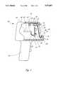
- FIG. 1is a partial cross-sectional, side elevational view of a symbology reader including a window according to the present invention.
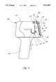
- FIG. 2is a reduced scale, partial cross section, side elevational view of the reader of FIG. 1 with a diagrammatic representation of a symbology being read.
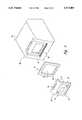
- FIG. 3is an exploded isometric view of a head portion of an alternative embodiment of the reader of FIG. 1 partially disassembled.
- FIG. 4is a partial cross-sectional, side elevational view of the reader of FIG. 3 with the window and gasket mounted in place.
- FIG. 5Ais an isometric view of an alternative window having a focusing element and two spotter beam lenses and usable with the reader embodiments of FIGS. 1 and 3.
- FIG. 5Bis a top plan view of the window of FIG. 5A constructed with a long reader-to-target plane distance.
- FIG. 5Cis a top plan view of the window of FIG. 5A constructed with a short reader-to-target plane distance.
- FIG. 6is a side cross-sectional view of an alternative embodiment having multiple window sheets.
- the present inventionis shown embodied in a symbology reader 40 having a head 42 and a handle 44.
- the head 42has a reader aperture 46 in a reading face 48 thereof to provide a passageway for light to enter or exit the head.
- An illumination source 50is mounted to a printed circuit board 52 within the head 42 and is oriented to emit light outwardly through the reader aperture 46.
- the illumination source 50may be a laser diode, an LED, or an array of LEDs.
- light from the illumination source 50exits the head 42 through the reader aperture 46 and illuminates a target object 54 bearing a symbology 56, as indicated by the broken line arrows.
- the symbology 56is a pattern of regions of varying reflectance that reflects some of the light from the illumination source 50 back toward the reading face 48.
- symbologiesare known. Examples include linear symbologies, such as bar codes, or may be multirow symbologies, such as PDF-417 or Code 49, or multilayer symbologies. Symbologies may also be of other types, such as "area" symbologies having a matrix of data cells.
- the light reflected by the symbology 56enters the head 42 through the reader aperture 46 and is detected by an optical detector 58 of a detector assembly 59.
- the detector assembly 59is a cylindrical housing holding optical elements such as focusing optics, apertures and filters.
- the reflected light received by the detector assembly 59will correspond to the pattern of reflectances of the symbology 56 and will be focused upon the optical detector 58 by the detector assembly 59.
- the optical detector 58upon detecting the light reflected from the symbology 56, generates an electrical signal which is carried by a cable 60 to a microprocessor 62 on a controller printed circuit board 64 within the head 42.
- the microprocessor 62in conjunction with conventional electronics 66 on the printed circuit board 64 decodes the electrical signal from the optical detector 58 to determine information represented by the symbology 56.
- a window 68advantageously covers the reader aperture 46 to protect the devices mounted within the head 42 and to prevent contamination.
- the window 68is an optically transmissive plate which mounts to the head 42 at the reading face 48.
- a substantially planar portion 67covers the reader aperture 46.
- An upper portion 69 of the windowextends rearwardly from an upper edge of the planar portion 67 to generally parallel an upper surface of the head 42.
- the planar portion 67 and upper portion 69define a curvature conforming substantially to the reading face 48.
- a window slot 78(best seen in FIG. 3) in the upper portion 69 is positioned and sized to accept a retaining tab 80 which projects upwardly from the head 42.
- the window slot 78is a rectangular slot through the upper portion 69 and centered between the left and right edges thereof.
- a gasket 70is seated between the window 68 and the head 42 to provide a seal to minimize the entry of moisture and contaminants into the head 42 through the reader aperture 46.
- the window 68is manufactured of a transparent acrylic, though other window materials, such as common transparent window plastic, are within the scope of the invention.
- the gasket 70is a compliant member, such as a foam rubber sheet, a silicone seal, or molded rubber. In the preferred embodiment, the gasket includes ribs (not shown) along one or both faces thereof to provide an improved seal against contaminants such as water.
- a boot 72preferably of rubber, covers part of the head 42.
- the boot 72has a pair of front lips 74, 76 which extend over edge regions of the window 68, helping to hold the window 68 in place and providing some physical shock protection. While the boot 72 is preferred, the boot may be eliminated in some applications, such as applications where little risk of physical impact is present.
- a useraligns the window gasket 70 with the reader aperture 46 such that a central opening 82 in the gasket 70 is aligned with the reader aperture 46.
- the gasket 70is then positioned in contact with the head 42.
- the window 68is aligned to the gasket 70 and the slot 78 is placed over the tab 80 by sliding the window 68 downwardly to place a ridge 84 at a lower end of the window 68 in a ridge slot 86 to guide the window 68 into its mounted position.
- the retaining tab 80enters into the window slot 78.
- the boot 72is then repositioned to cover the edges of the window 68, preventing it from sliding upwardly.
- the userTo remove the window 68, the user follows the opposite procedure. The user peels away the boot 72 by flexing it to disengage the lips 74, 76 from the window 68. The window 68 can then be slid upwardly to disengage the window slot 78 from the retaining tab 80 and to disengage the ridge 84 from the ridge slot 86. The window 68 is then free from the head 42.
- FIG. 3shows the head 42 of an alternative embodiment of the reader 40 with the window 68 and the gasket 70 removed.
- the window slot 78 in an upper section of the window 68is shaped to accept the flexible retaining tab 80 formed integrally to the head 42 (see also FIG. 4). Note that in the partially disassembled view of FIG. 3, the boot 72 is removed to more clearly show the correspondence of the gasket 70, and the head 42.
- the retaining tab 80differs from that described with respect to FIGS. 1 and 2.
- the tab 80includes a lip 88 which extends forward over the window 68 to hold the window in place when the ridge 84 is in the ridge slot 86.
- the usersimply bends the tab 80 rearwardly with his finger sufficiently to release the engagement of the lip 88 from the window 68 and position the lip to pass through the window slot 78.
- the windowcan then be lifted upwardly to withdraw the ridge 84 from the ridge slot 86, freeing the window from the head 42.
- the reverse procedureis followed to attach the window 68.
- the window 68is aligned to the reader aperture 46 with the ridge 84 above the ridge slot 86 and the gasket 70 between the window 68 and the head 42.
- the window 68is slid downwardly such that the ridge 84 enters the ridge slot 86 and the hooked tab 80 enters the window slot 78.
- the tab 80is bent back to allow the lip 88 to pass through the window slot 78.
- the tab 80is free to return to its unflexed position and the lip 88 projects forwardly to hold the window 68 in place.
- a mechanical clasp, a connector or other types of fastenermay lock the window 68 to the head 42 of the reader 40.
- the lip 88 on the tab 80eliminates the need for the boot 72 to hold the window 68 in its mounted position. Where the hooked tab structure of FIGS. 3 and 4 is used to hold the window 68 in place, the boot 72 can still be used for shock resistance; but, may be eliminated to ease detachment of the window.
- the window 68includes a polarizer 90 having a first region 92 and a second region 94.
- the first region 92transmits light of a first polarization and the second region 94 transmits light of a second polarization, orthogonal to the first polarization.
- the polarizer 90is formed from laminar sheets of polarizing material bonded to the planar portion 67 of the window. Alternatively, the polarizer 90 may be formed integrally to the planar portion 67, in a known fashion.
- the second region 94is positioned to receive light from the illumination source 50 while the first region 92 is positioned to receive reflected light traveling toward the detector assembly 59.
- Such orthogonal polarizerscan be useful for eliminating the effects of specular reflection.
- the windowin another embodiment of the window 68 shown in FIG. 5A, includes a focusing element 96 positioned to be aligned to the detector assembly 59 when the window is mounted to the reader 40, as is illustrated in FIGS. 5B and 5C.
- the focusing element 96is a lens, formed integral with the window 68. Such lenses can be formed by varying the index of refraction of the window material, or by varying the thickness of the window 68 in a known fashion.
- the focusing element 96 in conjunction with focusing elements in the detector assembly 59define a target plane 98 at a distance d 1 from the front face of the window 68.
- the window 68may be replaced by an alternate window 68' having a focusing element 96' of a different focal length, as shown in FIG. 5C.
- the focusing element 96', together with the focusing elements in the detector assembly 59,defines a target plane 98' at a distance d 2 , less than the distance d 1 .
- the windows 68, 68' of FIGS. 5B and 5Calso include a pair of targeting lenses 100, 102 formed integral with the window 68.
- the targeting lenses 100, 102cooperate with a pair of spotter beam sources 104, 106 shown in FIGS. 5B and 5C to provide a pair of spotter beams forming a pair of cursor images on a target object indicating to a user that the target object is aligned with the target plane 98 and the detector assembly 59 is aligned to read the symbology.
- the two spotter beam system of FIG. 5Butilizes the intersection or other placement of the cursor images on the target object to indicate that the reader 40 is at the proper distance d from the target plane 98.
- the alternate window 68'also includes a pair of targeting lenses 100', 102' having different focal lengths than the targeting lenses 100, 102 of FIG. 5B.
- the focal lengths of the targeting lenses 100', 102' of the alternate window 68'are chosen to cooperate with the pair of spotter beam sources 104, 106 to provide a pair of spotter beams to produce a pair of cursor images on a target object to indicate to the user that the reader 40 is aligned with the alternate target plane 98' and the detector assembly 59 is aligned to read the symbology in the alternate target plane 98'.
- the target planes 98, 98' of the reader 40may be defined for the detector assembly 59 simultaneously with alignment of the spotter beams to indicate the defined target plane 98 or 98'.
- a usermay thus adapt the reader 40 for use with target objects positioned close to the reader or for use with target objects to be read from a greater distance, simply by interchanging the replaceable windows 68, 68'.
- the focusing elements 96, 96' and the targeting lenses 100, 102, 100', 102'are shown as being formed integral with the window 68, it will be understood that the definition of the target plane 98 the focusing of the spotter beams may be achieved with a variety of focusing elements.
- lensesmay be surface mounted on the inner or outer surface of the window 68.
- segmented or gradient surfaces, such as Fresnel lenses or pyramidal structures,may be incorporated into or onto the window 68.
- the focusing element 96may be eliminated.
- the window 68also permits the reader 40 to be adapted for a variety of applications.
- the window 68may include a color selective filter integral to the window to filter out light at a wavelength other than the wavelength of the illumination source 50. This permits the reader's sensitivity to be improved, especially in high ambient light conditions.
- the color selective filtermay be made highly color selective, strongly blocking light at other wavelengths.
- the window 68may be substantially transparent to all wavelengths to permit the detector to receive more light.
- FIG. 6permits the optical effects of the window 68 to be varied through the use of multiple window sheets.
- two separate window sheets 68A and 68Bare mounted to the head 42, with the window sheet 68A overlaying the window sheet 68B.
- the window sheets 68A, 68Bare held in place by a flexible tab 80 having a pair of lips 81A, 81B which engage the upper edges of the window sheets 68A, 68B, respectively.
- the lower ends of the window sheets 68A, 68Brest upon respective shelves 110A, 110B and are held in place by a lip 112 which engages window sheet 68A.
- window sheet 68A, 68Ballows the color selectivity and/or transmissivity of the overall window 68 to be varied by a user. For example, if window sheet 68A is selected with a transmissivity of 75% and window sheet 68B is selected with a transmissivity of 50% the overall transmissivity would be 37.5%. If window sheet 68A is removed, leaving only window sheet 68B, the transmissivity would be 50%. If only window sheet 68A is used the transmissivity would be 75%. If neither window sheet 68A or 68B is used, the transmissivity would be 100%. Thus, four different levels of transmissivity can be obtained with only two window sheets 68A, 68B.
- window sheet 68Acould be replaced by a third window sheet (not shown) having a transmissivity of 25% giving a total transmissivity of 12.5% for the combination of this third window sheet and window sheet 68B.
- the third window sheetcould also be substituted for the window sheet 68B. If the head is adapted to hold all three window sheets, even greater flexibility can be achieved. While multiple window sheets have been described in terms of varying transmissivity, window sheets 68A and 68B may vary in ways other than transmissivity.
- each of the window sheets 68A, 68Bmay block light at selected wavelengths or polarizations to help block unwanted light having specific optical characteristics.
- several window sheetscan be carried with the symbology reader to improve adaptability for a variety of applications.
- the window 68 or specific window sheets 68A, 68Bmay be selected to permit the reader to be optimized for a specific type of symbology. Moreover, in specific environmental applications, the window may be selected to more quickly or effectively adapt to the environment. For example, in cold storage applications, condensation on an inner surface of the window is often a problem.
- the interchangeability of the windows 68, 68' or window sheets 68A, 68Ballows the window or window sheet to be removed from the reader 40 to permit a user to clean the inner surface to eliminate condensation.
- a window or window sheet coated with a low condensation coatingmay be attached to the reader for use in the cold storage application. Such adaptation can be realized using the single window or multiple window sheet embodiments.
Landscapes
- Engineering & Computer Science (AREA)
- Physics & Mathematics (AREA)
- General Physics & Mathematics (AREA)
- Theoretical Computer Science (AREA)
- Electromagnetism (AREA)
- Microelectronics & Electronic Packaging (AREA)
- Computer Hardware Design (AREA)
- Health & Medical Sciences (AREA)
- General Health & Medical Sciences (AREA)
- Toxicology (AREA)
- Artificial Intelligence (AREA)
- Computer Vision & Pattern Recognition (AREA)
- Image Input (AREA)
Abstract
Description
Claims (31)
Priority Applications (1)
| Application Number | Priority Date | Filing Date | Title |
|---|---|---|---|
| US08/293,386US5572007A (en) | 1994-08-19 | 1994-08-19 | Symbology reader with interchangeable window |
Applications Claiming Priority (1)
| Application Number | Priority Date | Filing Date | Title |
|---|---|---|---|
| US08/293,386US5572007A (en) | 1994-08-19 | 1994-08-19 | Symbology reader with interchangeable window |
Publications (1)
| Publication Number | Publication Date |
|---|---|
| US5572007Atrue US5572007A (en) | 1996-11-05 |
Family
ID=23128869
Family Applications (1)
| Application Number | Title | Priority Date | Filing Date |
|---|---|---|---|
| US08/293,386Expired - Fee RelatedUS5572007A (en) | 1994-08-19 | 1994-08-19 | Symbology reader with interchangeable window |
Country Status (1)
| Country | Link |
|---|---|
| US (1) | US5572007A (en) |
Cited By (35)
| Publication number | Priority date | Publication date | Assignee | Title |
|---|---|---|---|---|
| US5767494A (en)* | 1995-01-11 | 1998-06-16 | Olympus Optical Co., Ltd. | Information reproduction system for reproducing multimedia information recorded with optically readable code |
| US5828052A (en)* | 1996-10-24 | 1998-10-27 | Intermec Corporation | Ergonometric modular hand-held scanner, including an ergonomic handle and hilt |
| US5912452A (en)* | 1997-02-06 | 1999-06-15 | Intermec Corporation | Method and apparatus for reading one-and two-dimensional symbols with a linear detector |
| US5925867A (en)* | 1996-09-27 | 1999-07-20 | Oki Electric Industry Co., Ltd. | Optical device including multiple reflectors and optical systems for reading bar codes |
| US6131815A (en)* | 1997-09-29 | 2000-10-17 | Intermec Technologies Corporation | Slide-in tray for scanning device |
| US6247645B1 (en)* | 1999-01-25 | 2001-06-19 | International Business Machines Corporation | Optical reader with combined housing and light pipe |
| US20040134990A1 (en)* | 2003-01-09 | 2004-07-15 | Hand Held Products, Inc. | Housing for an optical reader |
| US20050109849A1 (en)* | 2002-01-11 | 2005-05-26 | Metrologic Instruments, Inc. | Method of generating a complex laser scanning pattern from a bioptical laser scanning system for providing 360° of omnidirectional bar code symbol scanning coverage at a point of sale station |
| US20060266839A1 (en)* | 2005-05-31 | 2006-11-30 | Symbol Technologies, Inc. | Retro-reflective scanner having exit window with positive optical power |
| US20060266840A1 (en)* | 2005-05-31 | 2006-11-30 | Symbol Technologies, Inc. | Feedback mechanism for scanner devices |
| US7159764B1 (en)* | 2003-05-30 | 2007-01-09 | Intermec Ip Corp. | Versatile window system for information gathering systems |
| US20070007350A1 (en)* | 2002-01-11 | 2007-01-11 | Metrologic Instruments, Inc. | Bioptical laser scanning system for providing six-sided 360-degree omnidirectional bar code symbol scanning coverage at a point of sale station |
| US7296748B2 (en) | 2002-01-11 | 2007-11-20 | Metrologic Instruments, Inc. | Bioptical laser scanning system providing 360° of omnidirectional bar code symbol scanning coverage at point of sale station |
| US20080023550A1 (en)* | 2006-07-31 | 2008-01-31 | Ming Yu | Curved window in electro-optical reader |
| US7347374B2 (en) | 2003-11-13 | 2008-03-25 | Metrologic Instruments, Inc. | Hand-supportable digital imaging-based bar code symbol reader employing an event-driven system control subsystem, automatic IR-based object detection, and trigger-switch activated image capture and processing subsystem |
| US7357325B2 (en) | 2003-11-13 | 2008-04-15 | Metrologic Instruments, Inc. | Hand-supportable imaging-based bar code symbol reader employing a CMOS-type image sensor using global exposure techniques |
| US7464877B2 (en) | 2003-11-13 | 2008-12-16 | Metrologic Instruments, Inc. | Digital imaging-based bar code symbol reading system employing image cropping pattern generator and automatic cropped image processor |
| US7516898B2 (en) | 2000-11-24 | 2009-04-14 | Metrologic Instruments, Inc. | Digital image capturing and processing system for producing and projecting a complex of coplanar illumination and imaging planes into a 3D imaging volume and controlling illumination control parameters in said system using the detected motion and velocity of object |
| US7546952B2 (en) | 2000-11-24 | 2009-06-16 | Metrologic Instruments, Inc. | Method of illuminating objects during digital image capture operations by mixing visible and invisible spectral illumination energy at point of sale (POS) environments |
| US7594609B2 (en) | 2003-11-13 | 2009-09-29 | Metrologic Instruments, Inc. | Automatic digital video image capture and processing system supporting image-processing based code symbol reading during a pass-through mode of system operation at a retail point of sale (POS) station |
| USD601557S1 (en) | 2007-08-06 | 2009-10-06 | Data Ltd., Inc. | Tablet computer |
| US7607581B2 (en) | 2003-11-13 | 2009-10-27 | Metrologic Instruments, Inc. | Digital imaging-based code symbol reading system permitting modification of system features and functionalities |
| US7708205B2 (en) | 2003-11-13 | 2010-05-04 | Metrologic Instruments, Inc. | Digital image capture and processing system employing multi-layer software-based system architecture permitting modification and/or extension of system features and functions by way of third party code plug-ins |
| US7841533B2 (en) | 2003-11-13 | 2010-11-30 | Metrologic Instruments, Inc. | Method of capturing and processing digital images of an object within the field of view (FOV) of a hand-supportable digitial image capture and processing system |
| USD635568S1 (en) | 2009-06-09 | 2011-04-05 | Data Ltd., Inc. | Tablet computer |
| USD638834S1 (en) | 2009-10-05 | 2011-05-31 | Data Ltd., Inc. | Tablet computer |
| ITMI20092188A1 (en)* | 2009-12-15 | 2011-06-16 | Datalogic Mobile S R L | OPTO-ELECTRONIC DEVICE FOR READING CODIFIED INFORMATION |
| USD654499S1 (en) | 2009-06-09 | 2012-02-21 | Data Ltd., Inc. | Tablet computer |
| US20120160919A1 (en)* | 2010-12-22 | 2012-06-28 | Symbol Technologies, Inc. | Imaging-based barcode readers having curved window |
| US8523076B2 (en) | 2012-01-10 | 2013-09-03 | Metrologic Instruments, Inc. | Omnidirectional laser scanning bar code symbol reader generating a laser scanning pattern with a highly non-uniform scan density with respect to line orientation |
| USD690296S1 (en) | 2011-02-01 | 2013-09-24 | Data Ltd., Inc. | Tablet computer |
| USD723560S1 (en)* | 2013-07-03 | 2015-03-03 | Hand Held Products, Inc. | Scanner |
| US20170140187A1 (en)* | 2015-11-13 | 2017-05-18 | Keyence Corporation | Portable Optical Reader |
| US10747976B2 (en)* | 2014-07-31 | 2020-08-18 | Keyence Corporation | Optical information reading device |
| GB2591864A (en)* | 2019-12-13 | 2021-08-11 | Zebra Tech Corp | Industrial digital barcode reader |
Citations (12)
| Publication number | Priority date | Publication date | Assignee | Title |
|---|---|---|---|---|
| JPS6134681A (en)* | 1984-07-26 | 1986-02-18 | Tokyo Electric Co Ltd | Optical reader |
| US4621189A (en)* | 1985-10-08 | 1986-11-04 | Telxon Corporation | Hand held data entry apparatus |
| JPS62147577A (en)* | 1985-12-23 | 1987-07-01 | Tokyo Electric Co Ltd | hand scanner |
| JPH02144681A (en)* | 1988-11-26 | 1990-06-04 | Nitto Kohki Co Ltd | portable data entry device |
| US4971410A (en)* | 1989-07-27 | 1990-11-20 | Ncr Corporation | Scanning and collection system for a compact laser |
| US4983818A (en)* | 1989-01-30 | 1991-01-08 | Metrologic Instruments, Inc. | Data acquisition system with laser scanner module |
| JPH03248287A (en)* | 1990-02-26 | 1991-11-06 | Oki Electric Ind Co Ltd | Bar code reader |
| JPH04149790A (en)* | 1990-10-15 | 1992-05-22 | Fujitsu Ltd | Handy type terminal equipment |
| JPH04233089A (en)* | 1990-12-28 | 1992-08-21 | Fujitsu Kiden Ltd | Bar code hand-held terminal |
| US5288984A (en)* | 1990-11-27 | 1994-02-22 | Nippondenso Co., Ltd. | Handy type bar code reader with a protective component holder |
| US5371348A (en)* | 1992-10-16 | 1994-12-06 | Khyber Technologies Corporation | Portable device for handsfree data entry with variably-positionable display/scanner module detachable for handheld use |
| US5410141A (en)* | 1989-06-07 | 1995-04-25 | Norand | Hand-held data capture system with interchangable modules |
- 1994
- 1994-08-19USUS08/293,386patent/US5572007A/ennot_activeExpired - Fee Related
Patent Citations (12)
| Publication number | Priority date | Publication date | Assignee | Title |
|---|---|---|---|---|
| JPS6134681A (en)* | 1984-07-26 | 1986-02-18 | Tokyo Electric Co Ltd | Optical reader |
| US4621189A (en)* | 1985-10-08 | 1986-11-04 | Telxon Corporation | Hand held data entry apparatus |
| JPS62147577A (en)* | 1985-12-23 | 1987-07-01 | Tokyo Electric Co Ltd | hand scanner |
| JPH02144681A (en)* | 1988-11-26 | 1990-06-04 | Nitto Kohki Co Ltd | portable data entry device |
| US4983818A (en)* | 1989-01-30 | 1991-01-08 | Metrologic Instruments, Inc. | Data acquisition system with laser scanner module |
| US5410141A (en)* | 1989-06-07 | 1995-04-25 | Norand | Hand-held data capture system with interchangable modules |
| US4971410A (en)* | 1989-07-27 | 1990-11-20 | Ncr Corporation | Scanning and collection system for a compact laser |
| JPH03248287A (en)* | 1990-02-26 | 1991-11-06 | Oki Electric Ind Co Ltd | Bar code reader |
| JPH04149790A (en)* | 1990-10-15 | 1992-05-22 | Fujitsu Ltd | Handy type terminal equipment |
| US5288984A (en)* | 1990-11-27 | 1994-02-22 | Nippondenso Co., Ltd. | Handy type bar code reader with a protective component holder |
| JPH04233089A (en)* | 1990-12-28 | 1992-08-21 | Fujitsu Kiden Ltd | Bar code hand-held terminal |
| US5371348A (en)* | 1992-10-16 | 1994-12-06 | Khyber Technologies Corporation | Portable device for handsfree data entry with variably-positionable display/scanner module detachable for handheld use |
Cited By (155)
| Publication number | Priority date | Publication date | Assignee | Title |
|---|---|---|---|---|
| US5767494A (en)* | 1995-01-11 | 1998-06-16 | Olympus Optical Co., Ltd. | Information reproduction system for reproducing multimedia information recorded with optically readable code |
| US5925867A (en)* | 1996-09-27 | 1999-07-20 | Oki Electric Industry Co., Ltd. | Optical device including multiple reflectors and optical systems for reading bar codes |
| US5828052A (en)* | 1996-10-24 | 1998-10-27 | Intermec Corporation | Ergonometric modular hand-held scanner, including an ergonomic handle and hilt |
| US5912452A (en)* | 1997-02-06 | 1999-06-15 | Intermec Corporation | Method and apparatus for reading one-and two-dimensional symbols with a linear detector |
| US6131815A (en)* | 1997-09-29 | 2000-10-17 | Intermec Technologies Corporation | Slide-in tray for scanning device |
| US6247645B1 (en)* | 1999-01-25 | 2001-06-19 | International Business Machines Corporation | Optical reader with combined housing and light pipe |
| US6648225B2 (en) | 1999-01-25 | 2003-11-18 | International Business Machines Corporation | Optical reader with combined housing and light pipe |
| US20050109847A1 (en)* | 2000-04-18 | 2005-05-26 | Metrologic Instruments, Inc. | Method of generating a complex laser scanning pattern from a bioptical laser scanning system for providing 360° of omnidirectional bar code symbol scanning coverage at a point of sale station |
| US7341192B2 (en) | 2000-04-18 | 2008-03-11 | Metrologic Instruments, Inc. | Method of generating a complex laser scanning pattern from a bioptical laser scanning system for providing 360° of omnidirectional bar code symbol scanning coverage at a point of sale station |
| US7661597B2 (en) | 2000-11-24 | 2010-02-16 | Metrologic Instruments, Inc. | Coplanar laser illumination and imaging subsystem employing spectral-mixing and despeckling of laser illumination |
| US7594608B2 (en) | 2000-11-24 | 2009-09-29 | Metrologic Instruments, Inc. | Automatic omnidirectional bar code symbol reading system employing linear-type and area-type bar code symbol reading stations within the system housing |
| US8042740B2 (en) | 2000-11-24 | 2011-10-25 | Metrologic Instruments, Inc. | Method of reading bar code symbols on objects at a point-of-sale station by passing said objects through a complex of stationary coplanar illumination and imaging planes projected into a 3D imaging volume |
| US7905413B2 (en) | 2000-11-24 | 2011-03-15 | Metrologic Instruments, Inc. | Digital image capturing and processing system employing a plurality of coplanar illumination and imaging subsystems for digitally imaging objects in a 3D imaging volume, and a globally-deployed object motion detection subsystem for automatically detecting and analyzing the motion of objects passing through said 3-D imaging volume |
| US7878407B2 (en) | 2000-11-24 | 2011-02-01 | Metrologic Instruments, Inc. | POS-based digital image capturing and processing system employing automatic object motion detection and spectral-mixing based illumination techniques |
| US7819326B2 (en) | 2000-11-24 | 2010-10-26 | Metrologic Instruments, Inc. | Network of digital image capturing systems installed at retail POS-based stations and serviced by a remote image processing server in communication therewith |
| US7815113B2 (en) | 2000-11-24 | 2010-10-19 | Metrologic Instruments, Inc. | Method of and system for returning a consumer product in a retail environment so as to prevent or reduce employee theft, as well as provide greater accountability for returned merchandise in retail store environments |
| US7806335B2 (en) | 2000-11-24 | 2010-10-05 | Metrologic Instruments, Inc. | Digital image capturing and processing system for automatically recognizing objects in a POS environment |
| US7806336B2 (en) | 2000-11-24 | 2010-10-05 | Metrologic Instruments, Inc. | Laser beam generation system employing a laser diode and high-frequency modulation circuitry mounted on a flexible circuit |
| US7793841B2 (en) | 2000-11-24 | 2010-09-14 | Metrologic Instruments, Inc. | Laser illumination beam generation system employing despeckling of the laser beam using high-frequency modulation of the laser diode current and optical multiplexing of the component laser beams |
| US7784695B2 (en) | 2000-11-24 | 2010-08-31 | Metrologic Instruments, Inc. | Planar laser illumination module (PLIM) employing high-frequency modulation (HFM) of the laser drive currents and optical multplexing of the output laser beams |
| US7775436B2 (en) | 2000-11-24 | 2010-08-17 | Metrologic Instruments, Inc. | Method of driving a plurality of visible and invisible LEDs so as to produce an illumination beam having a dynamically managed ratio of visible to invisible (IR) spectral energy/power during object illumination and imaging operations |
| US7770796B2 (en) | 2000-11-24 | 2010-08-10 | Metrologic Instruments, Inc. | Device for producing a laser beam of reduced coherency using high-frequency modulation of the laser diode current and optical multiplexing of the output laser beam |
| US7762465B2 (en) | 2000-11-24 | 2010-07-27 | Metrologic Instruments, Inc. | Device for optically multiplexing a laser beam |
| US7731091B2 (en) | 2000-11-24 | 2010-06-08 | Metrologic Instruments, Inc. | Digital image capturing and processing system employing automatic object detection and spectral-mixing based illumination techniques |
| US7673802B2 (en) | 2000-11-24 | 2010-03-09 | Metrologic Instruments, Inc. | Automatic POS-based digital image capturing and processing system employing a plurality of area-type illumination and imaging zones intersecting within the 3D imaging volume of the system |
| US7665665B2 (en) | 2000-11-24 | 2010-02-23 | Metrologic Instruments, Inc. | Digital illumination and imaging subsystem employing despeckling mechanism employing high-frequency modulation of laser diode drive current and optical beam multiplexing techniques |
| US7559474B2 (en) | 2000-11-24 | 2009-07-14 | Metrologic Instruments, Inc. | Automatic omnidirectional bar code symbol reading system employing linear-type and area-type bar code symbol reading stations within the system housing |
| US7661595B2 (en) | 2000-11-24 | 2010-02-16 | Metrologic Instruments, Inc. | Digital image capturing and processing system employing a plurality of area-type illuminating and imaging stations projecting a plurality of coextensive area-type illumination and imaging zones into a 3D imaging volume, and controlling operations therewithin using |
| US7658330B2 (en) | 2000-11-24 | 2010-02-09 | Metrologic Instruments, Inc. | Automatic POS-based digital image capturing and processing system employing object motion controlled area-type illumination and imaging operations |
| US7651028B2 (en) | 2000-11-24 | 2010-01-26 | Metrologic Instruments, Inc. | Intelligent system for automatically recognizing objects at a point of sale (POS) station by omni-directional imaging of the objects using a complex of coplanar illumination and imaging subsystems |
| US7614560B2 (en) | 2000-11-24 | 2009-11-10 | Metrologic Instruments, Inc. | Method of illuminating objects at a point of sale (POS) station by adaptively controlling the spectral composition of the wide-area illumination beam produced from an illumination subsystem within an automatic digital image capture and processing system |
| US7611062B2 (en) | 2000-11-24 | 2009-11-03 | Metrologic Instruments, Inc. | Omni-directional digital image capturing and processing system employing coplanar illumination and imaging planes and area-type illumination and imaging zones with the horizontal and vertical sections of the system housing |
| US8172141B2 (en) | 2000-11-24 | 2012-05-08 | Metrologic Instruments, Inc. | Laser beam despeckling devices |
| US7588188B2 (en) | 2000-11-24 | 2009-09-15 | Metrologic Instruments, Inc. | Pos-based digital image capturing and processing system using automatic object detection, spectral-mixing based illumination and linear imaging techniques |
| US7584892B2 (en) | 2000-11-24 | 2009-09-08 | Metrologic Instruments, Inc. | Digital-imaging based code symbol reading system employing a plurality of coplanar illumination and imaging subsystems, each having a local object motion detection subsystem for automatic detecting objects within the 3D imaging volume, and a local control subsystem for transmitting object detection state data to a global control subsystem for managing the state of operation of said coplanar illumination and imaging subsystems |
| US7581680B2 (en) | 2000-11-24 | 2009-09-01 | Metrologic Instruments, Inc. | Omni-directional digital image capturing and processing system employing coplanar illumination and imaging stations in horizontal and vertical housing sections of the system |
| US7578442B2 (en) | 2000-11-24 | 2009-08-25 | Metrologic Instruments, Inc. | Method of and apparatus for identifying consumer products in a retail environment when bar code symbols on the products are not readable or have been removed from packaging |
| US7578445B2 (en) | 2000-11-24 | 2009-08-25 | Metrologic Instruments, Inc. | Automatic POS-based digital image capturing and processing system employing object motion controlled area-type illumination and imaging operations |
| US7575170B2 (en) | 2000-11-24 | 2009-08-18 | Metrologic Instruments, Inc. | POS-based digital image capturing and processing system using automatic object detection, spectral-mixing based illumination and linear imaging techniques |
| US7516898B2 (en) | 2000-11-24 | 2009-04-14 | Metrologic Instruments, Inc. | Digital image capturing and processing system for producing and projecting a complex of coplanar illumination and imaging planes into a 3D imaging volume and controlling illumination control parameters in said system using the detected motion and velocity of object |
| US7520433B2 (en) | 2000-11-24 | 2009-04-21 | Metrologic Instruments, Inc. | Method for intelligently controlling the illumination and imagine of objects as they are moved through the 3D imaging volume of a digital image capturing and processing system |
| US7527204B2 (en) | 2000-11-24 | 2009-05-05 | Metrologic Instruments, Inc. | Omni-directional digital image capturing and processing system comprising coplanar illumination and imaging stations automatically detecting object motion and velocity and adjusting exposure and/or illumination control parameters therewithin |
| US7575169B2 (en) | 2000-11-24 | 2009-08-18 | Metrologic Instruments, Inc. | Digital image capturing and processing system for producing and projecting a plurality of coextensive area-type illumination and imaging zones into a 3D imaging volume and controlling illumination control parameters in said system using the detected motion of objects present therewithin |
| US7530497B2 (en) | 2000-11-24 | 2009-05-12 | Metrologic Instruments, Inc. | Digital image capturing and processing system employing an image capturing and processing module and an integrated electronic weigh scale module having a load cell centrally located with respect to said image capturing and processing module |
| US7533820B2 (en) | 2000-11-24 | 2009-05-19 | Metrologic Instruments, Inc. | Digital image capturing and processing system employing coplanar illumination and imaging stations which generate coplanar illumination and imaging planes only when and where an object is being moved within the 3D imaging volume |
| US7533823B2 (en) | 2000-11-24 | 2009-05-19 | Metrologic Instruments, Inc. | Digital image capturing and processing system employing a plurality of coplanar illuminating and imaging stations projecting a plurality of coplanar illumination and imaging planes into a 3D imaging volume, and controlling operations therewithin using control data derived from motion data collected from the automated detection of objects passing through said 3D imaging volume |
| US7537165B2 (en) | 2000-11-24 | 2009-05-26 | Metrologic Instruments, Inc. | Omni-directional digital image capturing and processing system employing coplanar illumination and imaging planes and area-type illumination and imaging zones within the system housing |
| US7540424B2 (en) | 2000-11-24 | 2009-06-02 | Metrologic Instruments, Inc. | Compact bar code symbol reading system employing a complex of coplanar illumination and imaging stations for omni-directional imaging of objects within a 3D imaging volume |
| US7540422B2 (en) | 2000-11-24 | 2009-06-02 | Metrologic Instruments, Inc. | Digital image capturing and processing system employing imaging window protection plate having an aperture pattern and being disposed over said imaging window and beneath which resides a plurality of coplanar illumination and imaging stations |
| US7571859B2 (en) | 2000-11-24 | 2009-08-11 | Metrologic Instruments, Inc. | Digital-imaging based code symbol reading system employing a plurality of coplanar illumination and imaging subsystems, global object motion detection subsystem for automatically detecting objects within its 3D imaging volume, and global control subsystem for managing the state of operation of said coplanar illumination and imaging substems |
| US7571858B2 (en) | 2000-11-24 | 2009-08-11 | Metrologic Instruemtns, Inc. | POS-based digital image capturing and processing system using automatic object detection, spectral-mixing based illumination and linear imaging techniques |
| US7543749B2 (en) | 2000-11-24 | 2009-06-09 | Metrologic Instruments, Inc. | Digital image capturing and processing system having a plurality of coplanar illumination and imaging subsystems, each employing a dual-type coplanar linear illumination and imaging engine that supports image-processing based object motion and velocity detection, and automatic image formation and detection along the coplanar illumination and imaging plane produced thereby |
| US7568626B2 (en) | 2000-11-24 | 2009-08-04 | Metrologic Instruments, Inc. | Automatic POS-based digital image capturing and processing system employing a plurality of area-type illumination and imaging zones intersecting within the 3D imaging volume of the system |
| US7546952B2 (en) | 2000-11-24 | 2009-06-16 | Metrologic Instruments, Inc. | Method of illuminating objects during digital image capture operations by mixing visible and invisible spectral illumination energy at point of sale (POS) environments |
| US7556199B2 (en) | 2000-11-24 | 2009-07-07 | Metrologic Instruments, Inc. | Digital image capturing and processing system employing a plurality of coplanar illuminating and imaging stations projecting a complex of coplanar illumination and imaging planes into a 3D imaging volume so as to support pass-through and presentation modes of digital imaging at a point of sale (POS) environment |
| US7510118B2 (en) | 2002-01-11 | 2009-03-31 | Metrologic Instruments, Inc. | Bar code symbol scanning system employing time-division multiplexed laser scanning and signal processing to avoid optical cross-talk and other unwanted light interference |
| US7422156B2 (en) | 2002-01-11 | 2008-09-09 | Metrologic Instruments, Inc. | Bioptical laser scanning system for providing six-sided 360-degree omnidirectional bar code symbol scanning coverage at a point of sale station |
| US20050109849A1 (en)* | 2002-01-11 | 2005-05-26 | Metrologic Instruments, Inc. | Method of generating a complex laser scanning pattern from a bioptical laser scanning system for providing 360° of omnidirectional bar code symbol scanning coverage at a point of sale station |
| US20070007350A1 (en)* | 2002-01-11 | 2007-01-11 | Metrologic Instruments, Inc. | Bioptical laser scanning system for providing six-sided 360-degree omnidirectional bar code symbol scanning coverage at a point of sale station |
| US20070017995A1 (en)* | 2002-01-11 | 2007-01-25 | Metrologic Instruments, Inc. | Bioptical laser scanning system for providing six-sided omnidirectional bar code symbol scanning coverage at a point of sale station |
| US7296748B2 (en) | 2002-01-11 | 2007-11-20 | Metrologic Instruments, Inc. | Bioptical laser scanning system providing 360° of omnidirectional bar code symbol scanning coverage at point of sale station |
| US7314176B2 (en) | 2002-01-11 | 2008-01-01 | Metrologic Instruments, Inc. | Method of generating a complex laser scanning pattern from a bioptical laser scanning system for providing 360° of omnidirectional bar code symbol scanning coverage at a point of sale station |
| US7740175B2 (en) | 2002-01-11 | 2010-06-22 | Metrologic Instruments, Inc. | Point-of-sale (POS) based laser scanning system providing six-sided 360 degree omni-directional bar code symbol scanning coverage at a POS station |
| US7374094B2 (en) | 2002-01-11 | 2008-05-20 | Metrologic Instruments, Inc. | Bioptical laser scanning system for providing six-sided omnidirectional bar code symbol scanning coverage at a point of sale station |
| US20040134990A1 (en)* | 2003-01-09 | 2004-07-15 | Hand Held Products, Inc. | Housing for an optical reader |
| US7147162B2 (en) | 2003-01-09 | 2006-12-12 | Hand Held Products, Inc. | Housing for an optical reader |
| US7159764B1 (en)* | 2003-05-30 | 2007-01-09 | Intermec Ip Corp. | Versatile window system for information gathering systems |
| US7637433B1 (en) | 2003-11-13 | 2009-12-29 | Metrologic Instruments, Inc. | Digital image capture and processing system employing a micro-computing platform with an event-driven multi-tier modular software architecture and supporting an image-processing based illumination metering program for automatically adjusting illumination during object illumination and imaging operations |
| US8087588B2 (en) | 2003-11-13 | 2012-01-03 | Metrologic Instruments, Inc. | Digital image capture and processing system having a single printed circuit (PC) board with a light transmission aperture, wherein a first linear array of visible light emitting diodes (LEDs) are mounted on the rear side of the PC board for producing a linear targeting illumination beam, and wherein a second linear array of visible LEDs are mounted on the front side of said PC board for producing a field of visible illumination within the field of view (FOV) of the system |
| US7588190B2 (en) | 2003-11-13 | 2009-09-15 | Metrologic Instruments, Inc. | Digital-imaging code symbol reading system supporting automatic programming of system parameters for automatic configuration of said system in hands-on and hands-free modes of operation |
| US7594609B2 (en) | 2003-11-13 | 2009-09-29 | Metrologic Instruments, Inc. | Automatic digital video image capture and processing system supporting image-processing based code symbol reading during a pass-through mode of system operation at a retail point of sale (POS) station |
| US7490774B2 (en) | 2003-11-13 | 2009-02-17 | Metrologic Instruments, Inc. | Hand-supportable imaging based bar code symbol reader employing automatic light exposure measurement and illumination control subsystem integrated therein |
| US9785811B2 (en) | 2003-11-13 | 2017-10-10 | Metrologic Instruments, Inc. | Image capture and processing system supporting a multi-tier modular software architecture |
| US7604175B2 (en) | 2003-11-13 | 2009-10-20 | Metrologic Instruments, Inc. | Method of reading bar code symbols using a digital-imaging based code symbol reading system employing an event-driven multi-tier modular software architecture and supporting automatic operating system login and loading of bar code symbol reading application |
| US7607581B2 (en) | 2003-11-13 | 2009-10-27 | Metrologic Instruments, Inc. | Digital imaging-based code symbol reading system permitting modification of system features and functionalities |
| US7611064B2 (en) | 2003-11-13 | 2009-11-03 | Metrologic Instruments, Inc. | Digital image capture and processing system having automatic illumination measurement and control capabilities realized using a photodetector operating independently of the image sensing array, and an image-processing based illumination metering program for automatically adjusting the illumination duration of the system during object illumination and imaging operations |
| US7487917B2 (en) | 2003-11-13 | 2009-02-10 | Metrologic Instruments, Inc. | Automatic digital-imaging based code symbol reading system supporting pass-through and presentation modes of system operation using automatic object direction detection, narrow-area and wide-area illumination control, and narrow-area and wide-area video image capture and processing techniques |
| US7484666B2 (en) | 2003-11-13 | 2009-02-03 | Metrologic Instruments, Inc. | Automatic digital-imaging based bar code symbol reading system supporting pass-through and presentation modes of system operation using automatic object direction detection and illumination control, and video image capture and processing techniques |
| US7624926B2 (en) | 2003-11-13 | 2009-12-01 | Metrologic Instruments, Inc. | Method of automatically reading code symbols on objects present within the field of view (FOV) of a hand-supportable digital-imaging based code symbol reader, by simultaneously projecting an image cropping zone (ICZ) framing pattern and a field of illumination within the FOV during object illumination and imaging operations |
| US7637432B2 (en) | 2003-11-13 | 2009-12-29 | Metrologic Instruments, Inc. | Automatic point-of-sale based code symbol reading system employing automatic object motion detection and illumination control, and digital video image capturing and processing techniques |
| US7559475B2 (en) | 2003-11-13 | 2009-07-14 | Metrologic Instruments, Inc. | Automatic digital-imaging based bar code symbol reading system supporting a pass-through mode of system operation using automatic object direction detection and illumination control, and video image capture and processing techniques |
| US7469835B2 (en) | 2003-11-13 | 2008-12-30 | Metrologic Instruments, Inc. | Digital-imaging based code symbol reading system employing an event-driven multi-tier modular software architecture and supporting automatic operating system login and loading of code symbol reading application |
| US7654461B2 (en) | 2003-11-13 | 2010-02-02 | Metrologic Instruments, Inc, | Automatically-triggered digital video imaging based code symbol reading system employing illumination and imaging subsystems controlled in response to real-time image quality analysis |
| US7464877B2 (en) | 2003-11-13 | 2008-12-16 | Metrologic Instruments, Inc. | Digital imaging-based bar code symbol reading system employing image cropping pattern generator and automatic cropped image processor |
| US7494063B2 (en) | 2003-11-13 | 2009-02-24 | Metrologic Instruments, Inc. | Automatic imaging-based code symbol reading system supporting a multi-tier modular software architecture, automatic illumination control, and video image capture and processing techniques |
| US7407109B2 (en) | 2003-11-13 | 2008-08-05 | Metrologic Instruments, Inc. | Digital-imaging based code symbol reading system employing a micro-computing platform supporting an event-driven multi-tier modular software architecture |
| US7503498B2 (en) | 2003-11-13 | 2009-03-17 | Metrologic Instruments, Inc. | Hand-supportable digital image capturing and processing system employing an area-type image sensing array exposed to illumination from an LED-based illumination array only when all sensor elements in said image-sensing array are activated and in a state of integration |
| US7357325B2 (en) | 2003-11-13 | 2008-04-15 | Metrologic Instruments, Inc. | Hand-supportable imaging-based bar code symbol reader employing a CMOS-type image sensor using global exposure techniques |
| US7681799B2 (en) | 2003-11-13 | 2010-03-23 | Metrologic Instruments, Inc. | Method of reading code symbols using a digital image capturing and processing system employing a micro-computing platform with an event-driven multi-tier software architecture |
| US7708205B2 (en) | 2003-11-13 | 2010-05-04 | Metrologic Instruments, Inc. | Digital image capture and processing system employing multi-layer software-based system architecture permitting modification and/or extension of system features and functions by way of third party code plug-ins |
| US7712666B2 (en) | 2003-11-13 | 2010-05-11 | Metrologic Instruments, Inc. | Automatically-triggered digital video-imaging based code symbol reading system supporting dynamically controlled object illumination and digital video-imaging operations |
| US7845561B2 (en) | 2003-11-13 | 2010-12-07 | Metrologic Instruments, Inc. | Digital image capture and processing system supporting a periodic snapshot mode of operation wherein during each image acquisition cycle, the rows of image detection elements in the image detection array are exposed simultaneously to illumination |
| US7735737B2 (en) | 2003-11-13 | 2010-06-15 | Metrologic Instruments, Inc. | Automatically-triggered digital video-imaging based code symbol reading system supporting ambient illumination mode automatically selected by adaptive control process |
| US7503499B2 (en) | 2003-11-13 | 2009-03-17 | Metrologic Instruments, Inc. | Digital image capturing and processing system producing narrow-band illumination when image sensor elements in a state of integration, and simultaneously detecting narrow-band illumination using an area-type image sensor and independently-operated photo-detector |
| US7861936B2 (en) | 2003-11-13 | 2011-01-04 | Metrologic Instruments, Inc. | digital image capturing and processing system allowing third-parties to extend the features and functions of said system, and modify the standard behavior thereof without permanently modifying the standard features and functions thereof |
| US7770798B2 (en) | 2003-11-13 | 2010-08-10 | Metrologic Instruments, Inc. | Automatically-triggered digital video-imaging based code symbol reading system for use in a point-of-sale (POS) environment |
| US9355288B2 (en) | 2003-11-13 | 2016-05-31 | Metrologic Instruments, Inc. | Image capture and processing system supporting a multi-tier modular software architecture |
| US7510122B2 (en) | 2003-11-13 | 2009-03-31 | Metrologic Instruments, Inc. | Portable digital image capturing and processing system employing an area-type image sensing array exposed to illumination produced from an LED-based illumination array and measured using a photodector operated independently from said area-type image sensing array |
| US7513430B2 (en) | 2003-11-13 | 2009-04-07 | Metrologic Instruments, Inc. | Digital image capturing and processing system employing an area-type image sensing array exposed to narrow-band illumination from a narrow-band illumination subsystem for a time duration controlled using a photodetector operated independently from said area-type image sensing array |
| US7789309B2 (en) | 2003-11-13 | 2010-09-07 | Metrologic Instruments, Inc. | Automatic digital video-imaging based code symbol reading system employing illumination and imaging subsystems controlled within a control loop maintained as long as a code symbol has not been successfully read and the object is detected in the field of view of the system |
| US9104930B2 (en) | 2003-11-13 | 2015-08-11 | Metrologic Instruments, Inc. | Code symbol reading system |
| US7527206B2 (en) | 2003-11-13 | 2009-05-05 | Metrologic Instruments, Inc. | Method of setting the time duration of illumination from an LED-based illumination array employed in a digital imaging-based code symbol reader, using an image-processing based illumination metering program executed therewithin |
| US7575167B2 (en) | 2003-11-13 | 2009-08-18 | Metrologic Instruments, Inc. | Method of dynamically managing system control parameters in a digital image capture and processing system |
| US7540425B2 (en) | 2003-11-13 | 2009-06-02 | Metrologic Instruments, Inc. | Method of dynamically controlling illumination and image capturing operations in a digital image capture and processing system |
| US7815121B2 (en) | 2003-11-13 | 2010-10-19 | Metrologic Instruments, Inc. | Method of modifying and/or extending the standard features and functions of a digital image capture and processing system |
| US7543752B2 (en) | 2003-11-13 | 2009-06-09 | Metrologic Instruments, Inc. | Digital image capture and processing system employing a multi-mode illumination subsystem adaptable to ambient illumination levels |
| US7841533B2 (en) | 2003-11-13 | 2010-11-30 | Metrologic Instruments, Inc. | Method of capturing and processing digital images of an object within the field of view (FOV) of a hand-supportable digitial image capture and processing system |
| US7845559B2 (en) | 2003-11-13 | 2010-12-07 | Metrologic Instruments, Inc. | Hand-supportable digital image capture and processing system employing visible targeting illumination beam projected from an array of visible light sources on the rear surface of a printed circuit (PC) board having a light transmission aperture, and reflected off multiple folding mirrors and projected through the light transmission aperture into a central portion of the field of view of said system |
| US7845563B2 (en) | 2003-11-13 | 2010-12-07 | Metrologic Instruments, Inc. | Digital image capture and processing system employing an illumination subassembly mounted about a light transmission aperture, and a field of view folding mirror disposed beneath the light transmission aperture |
| US7347374B2 (en) | 2003-11-13 | 2008-03-25 | Metrologic Instruments, Inc. | Hand-supportable digital imaging-based bar code symbol reader employing an event-driven system control subsystem, automatic IR-based object detection, and trigger-switch activated image capture and processing subsystem |
| US7490778B2 (en) | 2003-11-13 | 2009-02-17 | Metrologic Instruments, Inc. | Method of reading code symbols using a hand-supportable digital image capturing and processing device employing a micro-computing platform supporting an event-driven multi-tier modular software architecture |
| US8844822B2 (en) | 2003-11-13 | 2014-09-30 | Metrologic Instruments, Inc. | Image capture and processing system supporting a multi-tier modular software architecture |
| US8479992B2 (en) | 2003-11-13 | 2013-07-09 | Metrologic Instruments, Inc. | Optical code symbol reading system employing an acoustic-waveguide structure for coupling sonic energy, produced from an electro-transducer, to sound wave ports formed in the system housing |
| US7900839B2 (en) | 2003-11-13 | 2011-03-08 | Metrologic Instruments, Inc. | Hand-supportable digital image capture and processing system having a printed circuit board with a light transmission aperture, through which the field of view (FOV) of the image detection array and visible targeting illumination beam are projected using a FOV-folding mirror |
| US8366005B2 (en) | 2003-11-13 | 2013-02-05 | Metrologic Instruments, Inc. | Hand-supportable digital image capture and processing system supporting a multi-tier modular software architecture |
| US8317105B2 (en) | 2003-11-13 | 2012-11-27 | Metrologic Instruments, Inc. | Optical scanning system having an extended programming mode and method of unlocking restricted extended classes of features and functionalities embodied therewithin |
| US7922089B2 (en) | 2003-11-13 | 2011-04-12 | Metrologic Instruments, Inc. | Hand-supportable digital image capture and processing system employing automatic object presence detection to control automatic generation of a linear targeting illumination beam within the field of view (FOV), and manual trigger switching to initiate illumination |
| US7950583B2 (en) | 2003-11-13 | 2011-05-31 | Metrologic Instruments, Inc | Automatic digital video imaging based code symbol reading system employing an automatic object motion controlled illumination subsystem |
| US7568625B2 (en) | 2003-11-13 | 2009-08-04 | Metpologic Instruments, Inc. | Hand-supportable digital image-processing based bar code symbol reading system employing image cropping zone (ICZ) framing and post-image capture cropping |
| US8157175B2 (en) | 2003-11-13 | 2012-04-17 | Metrologic Instruments, Inc. | Digital image capture and processing system supporting a presentation mode of system operation which employs a combination of video and snapshot modes of image detection array operation during a single cycle of system operation |
| US7967209B2 (en) | 2003-11-13 | 2011-06-28 | Metrologic Instruments, Inc. | Method of blocking a portion of illumination rays generated by a countertop-supported digital imaging system, and preventing illumination rays from striking the eyes of the system operator or nearby consumers during operation of said countertop-supported digital image capture and processing system installed at a retail point of sale (POS) station |
| US7980471B2 (en) | 2003-11-13 | 2011-07-19 | Metrologic Instruments, Inc. | Method of unlocking restricted extended classes of features and functionalities embodied within a digital image capture and processing system by reading feature/functionality-unlocking type code symbols |
| US7988053B2 (en) | 2003-11-13 | 2011-08-02 | Metrologic Instruments, Inc. | Digital image capture and processing system employing an image formation and detection subsystem having image formation optics providing a field of view (FOV) on an area-type image detection array, and a multi-mode illumination subsystem having near and far field LED-based illumination arrays for illuminating near and far field portions of said FOV |
| US7997489B2 (en) | 2003-11-13 | 2011-08-16 | Metrologic Instruments, Inc. | Countertop-based digital image capture and processing system having an illumination subsystem employing a single array of LEDs disposed behind an illumination focusing lens structure integrated within the imaging window, for generating a field of visible illumination highly confined below the field |
| US8011585B2 (en) | 2003-11-13 | 2011-09-06 | Metrologic Instruments, Inc. | Digital image capture and processing system employing a linear LED-based illumination array mounted behind an illumination-focusing lens component integrated within the imaging window of the system |
| US7546951B2 (en) | 2003-11-13 | 2009-06-16 | Meterologic Instruments, Inc. | Digital image capture and processing system employing real-time analysis of image exposure quality and the reconfiguration of system control parameters based on the results of such exposure quality analysis |
| US8047438B2 (en) | 2003-11-13 | 2011-11-01 | Metrologic Instruments, Inc. | Digital image capture and processing system employing an image formation and detection subsystem having an area-type image detection array supporting periodic occurrance of snap-shot type image acquisition cycles at a high-repetition rate during object illumination |
| US8052057B2 (en)* | 2003-11-13 | 2011-11-08 | Metrologic Instruments, Inc. | Method of programming the system configuration parameters of a digital image capture and processing system during the implementation of its communication interface with a host system without reading programming-type bar code symbols |
| US7854384B2 (en) | 2003-11-13 | 2010-12-21 | Metrologic Instruments, Inc. | Digital image capture and processing engine employing optical waveguide technology for collecting and guiding LED-based illumination during object illumination and image capture modes of operation |
| US8100331B2 (en) | 2003-11-13 | 2012-01-24 | Metrologic Instruments, Inc. | Digital image capture and processing system having a printed circuit (PC) board with light transmission aperture, wherein first and second field of view (FOV) folding mirrors project the FOV of a digital image detection array on the rear surface of said PC board, through said light transmission aperture |
| US8157174B2 (en) | 2003-11-13 | 2012-04-17 | Metrologic Instruments, Inc. | Digital image capture and processing system employing an image formation and detection system having an area-type image detection array supporting single snap-shot and periodic snap-shot modes of image acquisition during object illumination and imaging operations |
| US8132731B2 (en) | 2003-11-13 | 2012-03-13 | Metrologic Instruments, Inc. | Digital image capture and processing system having a printed circuit (PC) board with a light transmission aperture, wherein an image detection array is mounted on the rear side of said PC board, and a linear array of light emitting diodes (LEDS) is mounted on the front surface of said PC board, and aligned with an illumination-focusing lens structure integrated within said imaging window |
| US20060266840A1 (en)* | 2005-05-31 | 2006-11-30 | Symbol Technologies, Inc. | Feedback mechanism for scanner devices |
| US7204424B2 (en)* | 2005-05-31 | 2007-04-17 | Symbol Technologies, Inc. | Retro-reflective scanner having exit window with positive optical power |
| US7331524B2 (en)* | 2005-05-31 | 2008-02-19 | Symbol Technologies, Inc. | Feedback mechanism for scanner devices |
| US20060266839A1 (en)* | 2005-05-31 | 2006-11-30 | Symbol Technologies, Inc. | Retro-reflective scanner having exit window with positive optical power |
| US20080023550A1 (en)* | 2006-07-31 | 2008-01-31 | Ming Yu | Curved window in electro-optical reader |
| USD601557S1 (en) | 2007-08-06 | 2009-10-06 | Data Ltd., Inc. | Tablet computer |
| USD654499S1 (en) | 2009-06-09 | 2012-02-21 | Data Ltd., Inc. | Tablet computer |
| USD635568S1 (en) | 2009-06-09 | 2011-04-05 | Data Ltd., Inc. | Tablet computer |
| USD638834S1 (en) | 2009-10-05 | 2011-05-31 | Data Ltd., Inc. | Tablet computer |
| ITMI20092188A1 (en)* | 2009-12-15 | 2011-06-16 | Datalogic Mobile S R L | OPTO-ELECTRONIC DEVICE FOR READING CODIFIED INFORMATION |
| US8590793B2 (en)* | 2010-12-22 | 2013-11-26 | Symbol Technologies, Inc. | Imaging-based barcode readers having curved window |
| US20120160919A1 (en)* | 2010-12-22 | 2012-06-28 | Symbol Technologies, Inc. | Imaging-based barcode readers having curved window |
| USD690296S1 (en) | 2011-02-01 | 2013-09-24 | Data Ltd., Inc. | Tablet computer |
| US8523076B2 (en) | 2012-01-10 | 2013-09-03 | Metrologic Instruments, Inc. | Omnidirectional laser scanning bar code symbol reader generating a laser scanning pattern with a highly non-uniform scan density with respect to line orientation |
| USD723560S1 (en)* | 2013-07-03 | 2015-03-03 | Hand Held Products, Inc. | Scanner |
| USD766244S1 (en) | 2013-07-03 | 2016-09-13 | Hand Held Products, Inc. | Scanner |
| USD826233S1 (en) | 2013-07-03 | 2018-08-21 | Hand Held Products, Inc. | Scanner |
| US10747976B2 (en)* | 2014-07-31 | 2020-08-18 | Keyence Corporation | Optical information reading device |
| US9754146B2 (en)* | 2015-11-13 | 2017-09-05 | Keyence Corporation | Portable optical reader |
| US20170140187A1 (en)* | 2015-11-13 | 2017-05-18 | Keyence Corporation | Portable Optical Reader |
| GB2591864A (en)* | 2019-12-13 | 2021-08-11 | Zebra Tech Corp | Industrial digital barcode reader |
| US11132520B2 (en) | 2019-12-13 | 2021-09-28 | Zebra Technologies Corporation | Industrial digital barcode reader |
| GB2591864B (en)* | 2019-12-13 | 2022-05-25 | Zebra Tech Corp | Industrial digital barcode reader |
Similar Documents
| Publication | Publication Date | Title |
|---|---|---|
| US5572007A (en) | Symbology reader with interchangeable window | |
| US5541419A (en) | Symbology reader wth reduced specular reflection | |
| US9495573B2 (en) | Low profile illumination for direct part mark readers | |
| EP0312298B1 (en) | Bar code reader head | |
| US6105869A (en) | Symbol reading device including optics for uniformly illuminating symbology | |
| US5034619A (en) | Optical reader with dual vertically oriented photoemitters | |
| US10477059B2 (en) | Information reading device | |
| US6045047A (en) | Two-dimensional part reader having a focussing guide | |
| KR0155034B1 (en) | Uneven surface reader | |
| EP0610504A4 (en) | Information reading apparatus. | |
| KR910001586A (en) | Uneven surface data detection device | |
| JPH08211302A (en) | Sample stage of microscope | |
| US10796117B2 (en) | Fixed position reader of coded information and camera based checkout system using the same | |
| US5619029A (en) | Imaging enhancement for touch cameras | |
| WO1998018098A1 (en) | Camera for decoding machine readable images having diffuser | |
| US20100065641A1 (en) | System for increasing imaging quality | |
| CA2203924A1 (en) | Uneven surface image transfer apparatus | |
| US9785868B2 (en) | Reverse vending machine and method of detecting dirt in a reverse vending machine | |
| US5574272A (en) | Data symbol reader | |
| US5042821A (en) | Seal for optical scanner window | |
| JP2003256768A (en) | Information code reader | |
| US5198651A (en) | Laser diode device incorporating structure with integral scanning motor | |
| US7166831B2 (en) | Optical mouse with replaceable contaminant barrier | |
| US6937812B2 (en) | Multiple viewing angle cover having integral light pipe | |
| JP3511991B2 (en) | Optical information reader |
Legal Events
| Date | Code | Title | Description |
|---|---|---|---|
| AS | Assignment | Owner name:INTERMEC CORPORATION, WASHINGTON Free format text:ASSIGNMENT OF ASSIGNORS INTEREST;ASSIGNORS:ARAGON, JOEL T.;BUNCE, STEVEN M.;REEL/FRAME:007128/0400 Effective date:19940817 | |
| AS | Assignment | Owner name:INTERMEC IP CORPORATION, CALIFORNIA Free format text:ASSIGNMENT OF ASSIGNORS INTEREST;ASSIGNOR:INTERMEC TECHNOLOGIES CORPORATION;REEL/FRAME:009490/0672 Effective date:19980902 | |
| FPAY | Fee payment | Year of fee payment:4 | |
| FEPP | Fee payment procedure | Free format text:PAYOR NUMBER ASSIGNED (ORIGINAL EVENT CODE: ASPN); ENTITY STATUS OF PATENT OWNER: LARGE ENTITY | |
| FPAY | Fee payment | Year of fee payment:8 | |
| REMI | Maintenance fee reminder mailed | ||
| LAPS | Lapse for failure to pay maintenance fees | ||
| LAPS | Lapse for failure to pay maintenance fees | Free format text:PATENT EXPIRED FOR FAILURE TO PAY MAINTENANCE FEES (ORIGINAL EVENT CODE: EXP.); ENTITY STATUS OF PATENT OWNER: LARGE ENTITY | |
| STCH | Information on status: patent discontinuation | Free format text:PATENT EXPIRED DUE TO NONPAYMENT OF MAINTENANCE FEES UNDER 37 CFR 1.362 | |
| FP | Lapsed due to failure to pay maintenance fee | Effective date:20081105 |