US5571258A - Semi-automated medication dispenser - Google Patents
Semi-automated medication dispenserDownload PDFInfo
- Publication number
- US5571258A US5571258AUS08/502,118US50211895AUS5571258AUS 5571258 AUS5571258 AUS 5571258AUS 50211895 AUS50211895 AUS 50211895AUS 5571258 AUS5571258 AUS 5571258A
- Authority
- US
- United States
- Prior art keywords
- tube
- pill
- suction
- stationary
- retrieved
- Prior art date
- Legal status (The legal status is an assumption and is not a legal conclusion. Google has not performed a legal analysis and makes no representation as to the accuracy of the status listed.)
- Expired - Lifetime
Links
- 239000003814drugSubstances0.000titleclaimsabstractdescription98
- 229940079593drugDrugs0.000titleclaimsabstractdescription98
- 239000006187pillSubstances0.000claimsabstractdescription141
- 238000004891communicationMethods0.000claimsabstractdescription5
- 239000012530fluidSubstances0.000claimsabstractdescription5
- 238000002483medicationMethods0.000description32
- 239000002775capsuleSubstances0.000description8
- 238000000034methodMethods0.000description6
- 230000000717retained effectEffects0.000description6
- 238000004806packaging method and processMethods0.000description5
- 230000036961partial effectEffects0.000description5
- 239000000835fiberSubstances0.000description4
- 239000002184metalSubstances0.000description4
- 230000006835compressionEffects0.000description3
- 238000007906compressionMethods0.000description3
- 238000011109contaminationMethods0.000description3
- 239000004033plasticSubstances0.000description3
- 238000001514detection methodMethods0.000description2
- 230000006870functionEffects0.000description2
- 230000036541healthEffects0.000description2
- 230000002401inhibitory effectEffects0.000description2
- 230000033001locomotionEffects0.000description2
- 239000004081narcotic agentSubstances0.000description2
- 230000002441reversible effectEffects0.000description2
- 206010020751HypersensitivityDiseases0.000description1
- 238000013459approachMethods0.000description1
- 238000013475authorizationMethods0.000description1
- 230000008901benefitEffects0.000description1
- 230000008859changeEffects0.000description1
- 238000006243chemical reactionMethods0.000description1
- 238000013329compoundingMethods0.000description1
- 238000012790confirmationMethods0.000description1
- 238000010276constructionMethods0.000description1
- 239000006071creamSubstances0.000description1
- 230000000994depressogenic effectEffects0.000description1
- 239000000428dustSubstances0.000description1
- 238000007689inspectionMethods0.000description1
- 230000003993interactionEffects0.000description1
- 239000007788liquidSubstances0.000description1
- 239000000463materialSubstances0.000description1
- 230000013011matingEffects0.000description1
- 230000000474nursing effectEffects0.000description1
- 239000002674ointmentSubstances0.000description1
- 230000003287optical effectEffects0.000description1
- 239000000843powderSubstances0.000description1
- 239000000955prescription drugSubstances0.000description1
- 230000008569processEffects0.000description1
- 230000002829reductive effectEffects0.000description1
- 238000012552reviewMethods0.000description1
- 239000007787solidSubstances0.000description1
- 239000000126substanceSubstances0.000description1
- 239000000829suppositorySubstances0.000description1
- 239000003826tabletSubstances0.000description1
- 230000000007visual effectEffects0.000description1
- 230000003442weekly effectEffects0.000description1
Images


Classifications
- A—HUMAN NECESSITIES
- A61—MEDICAL OR VETERINARY SCIENCE; HYGIENE
- A61J—CONTAINERS SPECIALLY ADAPTED FOR MEDICAL OR PHARMACEUTICAL PURPOSES; DEVICES OR METHODS SPECIALLY ADAPTED FOR BRINGING PHARMACEUTICAL PRODUCTS INTO PARTICULAR PHYSICAL OR ADMINISTERING FORMS; DEVICES FOR ADMINISTERING FOOD OR MEDICINES ORALLY; BABY COMFORTERS; DEVICES FOR RECEIVING SPITTLE
- A61J7/00—Devices for administering medicines orally, e.g. spoons; Pill counting devices; Arrangements for time indication or reminder for taking medicine
- A61J7/0076—Medicament distribution means
- A61J7/0084—Medicament distribution means for multiple medicaments
- G—PHYSICS
- G07—CHECKING-DEVICES
- G07F—COIN-FREED OR LIKE APPARATUS
- G07F11/00—Coin-freed apparatus for dispensing, or the like, discrete articles
- G07F11/02—Coin-freed apparatus for dispensing, or the like, discrete articles from non-movable magazines
- G07F11/04—Coin-freed apparatus for dispensing, or the like, discrete articles from non-movable magazines in which magazines the articles are stored one vertically above the other
- G07F11/16—Delivery means
- G07F11/165—Delivery means using xyz-picker or multi-dimensional article picking arrangements
- G07F11/1657—Delivery means using xyz-picker or multi-dimensional article picking arrangements the picking arrangements using suction
- G—PHYSICS
- G07—CHECKING-DEVICES
- G07F—COIN-FREED OR LIKE APPARATUS
- G07F17/00—Coin-freed apparatus for hiring articles; Coin-freed facilities or services
- G07F17/0092—Coin-freed apparatus for hiring articles; Coin-freed facilities or services for assembling and dispensing of pharmaceutical articles
- A—HUMAN NECESSITIES
- A61—MEDICAL OR VETERINARY SCIENCE; HYGIENE
- A61J—CONTAINERS SPECIALLY ADAPTED FOR MEDICAL OR PHARMACEUTICAL PURPOSES; DEVICES OR METHODS SPECIALLY ADAPTED FOR BRINGING PHARMACEUTICAL PRODUCTS INTO PARTICULAR PHYSICAL OR ADMINISTERING FORMS; DEVICES FOR ADMINISTERING FOOD OR MEDICINES ORALLY; BABY COMFORTERS; DEVICES FOR RECEIVING SPITTLE
- A61J1/00—Containers specially adapted for medical or pharmaceutical purposes
- A61J1/03—Containers specially adapted for medical or pharmaceutical purposes for pills or tablets
Definitions
- This inventionpertains to semi-automated medication dispensers, particularly to medication dispensers suitable for dispensing multiple medications to multiple patients with minimal risk of error, pilferage, and contact with the medications.
- U.S. Pat. No. 3,848,112discloses magnetically coded identification tags for correlating the identity of a patient to the patient's prescriptions, samples, and the like.
- U.S. Pat. No. 4,695,954discloses a medication dispensing system for use with a single patient, in which all medications to be dispensed at a particular time for that patient are manually loaded into a particular compartment of the device, and the device allows access to each compartment at the appropriate time.
- U.S. Pat. No. 4,971,221discloses a drug dispenser with a monitor such as an optical sensor to detect when a dose of the drug has been dispensed.
- U.S. Pat. No. 4,967,928discloses a medication cart with an on-board computer system in which unsecured medications are stored in conventional cabinet cubicles; and in which secured narcotics are either stored in a single-dose, automatic dispenser apparatus requiring special packaging for dispensing doses of the narcotics, or are stored in a locked conventional cubical.
- U.S. Pat. No. 3,917,045discloses an automatic drug dispensing apparatus which dispenses drugs from cartridges, each of which holds a plurality of individual drug dosages.
- U.S. Pat. No. 4,847,764discloses a system for dispensing medications in a health care institution in which a central computer system controls a plurality of remote medication dispensers.
- a novel, semi-automated medication dispenserhas been invented that greatly simplifies the logistics of correctly dispensing multiple medications to multiple patients in the correct dosages at the correct times, in a manner that is cost-efficient and labor-efficient, that greatly reduces the probability of errors, and that inhibits pilferage.
- the novel dispensercan be loaded with many days' worth of medication (e.g., 30 days) at one time, and requires no special packaging for the medications.
- the novel dispenseris controlled by a computer. Patient information and physician orders are entered into the computer's memory. Medications needed by all the patients in a ward are loaded into individual compartments, for example by a pharmacist. Many days' worth of medication may often be loaded at once.
- the computerAfter the medications are loaded into the dispenser, access to the individual compartments is controlled by the computer.
- the computerWhen a proper password is entered--for example by the dispensing nurse--followed by identifying information for a particular patient, the computer allows access to only those compartments containing medications that are appropriate for the individual patient at that time.
- a variety of suction tubesmay be employed to physically retrieve the desired medication.
- the computercontrols the dosage of the medication being dispensed as well, by controlling the number of pills dispensed. Thus, each patient receives all appropriate medications, and only the appropriate medications.
- the computeralso simultaneously makes a record of the medications administered to each patient. In the entire process, human hands need never touch the tablets or capsules being dispensed to the patient.
- FIG. 1aillustrates a longitudinal view of a medication-dispensing cart in accordance with the present invention.
- FIG. 1billustrates a partial cross-sectional view of the same cart.
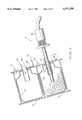
- FIG. 2illustrates a cross-section of two containers used in the cart.
- FIGS. 3a and 3billustrate two positions of a suction tube that may be used in conjunction with this invention.
- FIG. 4aillustrates an elevation view of a first alternate embodiment of a suction tube which can be used with the present invention.
- FIG. 4billustrates a partial cross-sectional view of the embodiment in FIG. 4a.
- FIGS. 5a and 5billustrate a sectional view of the adjustable outlet of FIG. 4a and 4b in two positions.
- FIG. 6aillustrates a partial cross-sectional view of a second alternate embodiment of a suction tube in a receive position.
- FIG. 6billustrates the embodiment of FIG. 6a in a dispensing position.
- FIGS. 7a and 7billustrate an elevation view of a third alternate embodiment of a suction tube with an adjustable aperture in a large and small open position, respectively.
- FIGS. 7c and 7dillustrate a partial cross-sectional view of the embodiment in FIGS. 7a and 7b, respectively.
- FIGS. 8a through 8eillustrate the adjustable inlet of FIGS. 7a through 7d in various positions.
- FIGS. 1-3One embodiment of the present invention is illustrated in FIGS. 1-3.
- FIG. 1aillustrates a longitudinal view of a medication-dispensing can in accordance with the present invention
- FIG. 1billustrates a partial cross-sectional view of the same cart.
- the cart 2preferably has optional wheels or casters 4, or other means of locomotion to make it mobile. Alternatively, the wheels could be omitted, and the cart could be stationary.
- Optional handles 6 on either end of the cartallow the cart to be maneuvered easily.
- a suction tube 12is used to withdraw pills and tablets from containers 8, as is explained further below.
- a computer 14is shown schematically.
- Computeris used in the specification and the claims in a broad sense, and would include, for example, a microprocessor or a microcontroller, along with associated memory elements and input/output devices such as are known in the art of electronics today.
- Not shownare various input/output devices and connections for the computer whose operation and construction will be understood by those of skill in the art in electronics after reading the present disclosure.
- Input/output devices for the computermay include, for example, a keyboard, trackball, and/or mouse used by the operator of the cart, a port for uploading/downloading data to or from another computer, a modem for uploading/downloading data to or from another computer via a telephone line, a monitor, a printer, and various input/output connections between the computer and the devices that it controls, such as the containers 8, drawers 10, and suction tube 12.
- Metal lid 16slides out of the way into cart 2, between containers 8 and drawers 10, when the cart is in use.
- metal lid 16may be slid forward, and swung on a hinge or pivot up and over containers 8.
- Lid 16may then by physically locked over containers 8, in a configuration not illustrated, to prevent unauthorized access to the medications in the containers. (Drawers 10 are automatically locked by the computer at all times except when the computer specifically allows access.) Thus all medications contained in the cart are locked away to prevent unauthorized access when the cart is not in use.
- the cartalso be placed in a locked room when not in use.
- the cartmay optionally be equipped with a motion sensor to sound an alarm if the cart is moved without an appropriate password first being entered into the computer. Note that closing lid 16 also has the benefit of inhibiting contamination of the drugs within the containers 8 by dust or the like.
- FIG. 2illustrates a cross-section of two containers 8.
- the upper containeris shown empty except for medication jar 18, while the lower container contains tablets or capsules of medication 20 in jar 18.
- Suction tube 12is shown entering the lower container to withdraw one or more tablets or capsules 20.
- Each container 8is adapted to hold a bottle or jar 18 holding the capsules or tablets 20. Alternatively, there need be no bottle or jar, and the capsules or tablets may be placed directly in the container.
- Each container 8has a signal light 22, which may for example be either red or green.
- the containerhas a plastic tube orifice 24 to allow entry and exit of suction tube 12; the tube orifice preferably has a lip on the upper surface as illustrated, to facilitate dropping an extracted pill into a paper cup as described below.
- the tube orificealso has a fiber optic or other sensor (such as a microswitch) 26 to indicate when an authorized or unauthorized entry is made into the container; in the case of an unauthorized entry, it may be desirable to have an alarm sound to indicate that a possible theft is in progress.
- the exterior of each containerhas a label holder 28 to identify the medication that it contains, and preferably has a platform 30 to hold a collection cup 32.
- FIGS. 3a and 3billustrate the suction tube 12 in greater detail.
- Am outer sheath 34made of a flexible clear plastic covers part of the structure.
- Inner cylinder 36which picks up a pill, is connected via rubber hose 38 to a suction motor (not shown) inside cart 2.
- the suction tubeneed not be connected to the cart as illustrated in FIG. 1a, but could instead be part of a portable unit containing a small vacuum motor in the handle.
- Glide collar 40positions the inner cylinder in the tube orifice 24 when the inner cylinder is inserted in a container, and allows freedom of rotation to allow the inner cylinder 36 to find a pill within the container.
- the assemblyallows fiber optic (or other) sensor 42 at the end of the sheath to be pushed over the end of inner cylinder 36 to confirm whether a tablet has been picked up; if so, a signal is sent to the computer indicating success, and causing indicator light 44 to turn on.
- Handle plate 46is attached to sheath 34, and slides over inner cylinder 36. As depicted in FIG. 3b, pushing on handle plate 46 pushes the end of sheath 34 over the end of inner cylinder 36 to allow the fiber optic sensor 42 to function as described.
- Spring 48 between handle plate 46 and handle 50urges the handle plate back to its starting position after such an inspection.
- Microswitch 52detects when the end of sheath 34 is extended past the end of inner cylinder 36 in this manner, and microswitch 52 then activates fiber optic sensors 42.
- FIGS. 4a and 4bAn alternative embodiment 60 to suction tube 12 is shown in FIGS. 4a and 4b, comprising, in part, a handle 61 which houses a suction motor 62 manually controlled by an electrical switch 63.
- Power cord 66extends from handle 61 and is connected between suction motor 62 and an external power source.
- Stationary tube 64is attached to handle 61 by an air-tight seal (not shown), but is in fluid communication with suction motor 62 to allow suction to be created within stationary tube 64.
- Screen 65is also attached inside stationary tube 64 and includes a mesh which is large enough to allow free flow of air through stationary tube 64, but small enough to prevent the passage of the smallest available pill 73 used in the medication administration system.
- Inner tube 67is rotatably disposed within stationary tube 64 and is held therein by tab 68 extending through an adjustment slot 69 formed in stationary tube 64.
- the relationship between tab 68 and adjustment slot 69are such that inner tube 67 may be rotated by a force exerted on tab 68 in either direction.
- the extent of rotation of inner tube 67is defined by the edges of adjustment slot 69, and is preferably about 60-90 degrees.
- Inner and outer pill slots 70,71are also formed into inner tube 67 and stationary tube 64, respectively, to create a pill exit aperture 72 for allowing pills 73 to exit the suction tube 60 after being guided there by inner tube 67. Both inner and outer pill slots 70,71 may be identical in shape and size, and their alignment is controlled by the rotation of inner tube 67.
- inner pill slot 70 and outer pill slot 71may be aligned so that pill exit aperture 72 is completely open and large pills may exit suction tube 60.
- inner pill slot 70 and outer pill slot 71may be entirely offset so that pill exit aperture 72 is closed and no medication may exit from suction tube.
- the size of pill exit aperture 72may be controlled using intermediate positions of tab 68 so that varying size medication may be collected and dispensed.
- inner tube 67 or stationary tube 64may be inscribed or marked with gradations showing the percentage of opening or closing of pill exit aperture 72.
- infrared sensor 76having an emitter and a detector, is located within inner tube 67 to sense the passage of a pill through inner tube 67, as shown in FIG. 4B.
- the passage of a pill 73interrupts the detection of infrared energy from the emitter, and an audible or visual signal is generated by the computer.
- the suction motor 62may be deactivated as the tube 67 is rotated upward to allow pill 73 to reach pill exit aperture 72, to ensure that no further pills are retrieved.
- collection tube 75is either permanently attached to inner tube 67 or frictionally held in place within inner tube 67.
- Release lever 74acts as a pill obstruction means and is rotatably mounted to a pin 82 across slot 84 and held within pivot base 77 on collection tube 75.
- Release lever 74includes a lower portion 78 which obstructs the passage of pills 73 through collection tube 75, but which does not inhibit the flow of air therethrough.
- Resilient band 79such as an O-ring or rubber band, is retained by notches 80,81 on both release lever 74 and collection tube 75, respectively, and urges lower portion 78 of release lever 74 into collection tube 75.
- the relative sizes of collection tube 75 inner diameter and lower portion 78are such that the free flow of air through collection tube 75 is permitted.
- lower portion 78should be sufficient to prevent the passage of the smallest available pill 73 used in the medication administration system, and lower portion 78 should be close enough to the end of collection tube 75 so that only a single pill 73 is retained by the suction.
- pill exit aperture 72can also be used to fine tune the suction motor 62 strength for certain medication. For instance, larger pills will typically require higher suction to keep the pills 73 within the end of the suction tube 60. Thus, the pill exit aperture 72 may be reduced or closed for larger pills to ensure their retrieval. Conversely for small pills, the pill exit aperture 72 may be increased (thus reducing suction strength) so that only one pill 73 is retained by the tip of suction tube 60 until the release lever 74 is depressed.
- handle 61further includes collection cup retaining means 83, such as a small bracket, which firmly holds collection cup 32 below pill exit aperture 72.
- collection cup retaining means 83such as a small bracket, which firmly holds collection cup 32 below pill exit aperture 72.
- FIGS. 6a and 6bA second alternative embodiment 100 to suction tube 12 is shown in FIGS. 6a and 6b, comprising, in part, a handle 61, suction motor 62, electrical switch 63, and power cord 66 identical to the corresponding features in the embodiment of FIGS. 4a and 4b.
- First stationary tube 101is attached to handle 61 by an air-tight seal (not shown), but is in fluid communication with suction motor 62 to allow suction to be created within first stationary tube 101.
- Second stationary tube 102extends prominently from handle 61 and is either separately attached coaxially to first stationary tube 101 (as shown in FIGS. 6a and 6b) or formed as a part of first stationary tube 101.
- Helical compression spring 103is seated within second stationary tube 102 and retained therein by abutment with collection tube 104.
- Collection tube 104includes an airflow inlet 105 and a base 106, through which is formed an airflow outlet 107.
- Inlet 105further includes pill obstruction means 116, which prevents a pill 73 from passing through collection tube 104, but which does not inhibit the flow of air therethrough.
- Pill obstruction means 116can take any number of forms, but is preferably a screen placed across the inner diameter of collection tube 104.
- pill obstruction means 116should be close enough to the inlet 105 of collection tube 104 so that only a single pill 73 is retained by the suction.
- Collection tube 104is sized to slide freely within second stationary tube 102, and traverses between an extended position and a retracted position, both shown in FIGS. 6a and 6b, respectively.
- the extended and retracted positionsare defined by the interaction between a longitudinal slot 108 formed through second stationary tube 102 and a tab 109 attached to collection tube 104 which extends through longitudinal slot 108.
- the extended position of FIG. 6asimply results from the force applied by compression spring 103 against collection tube 104, and by the contact between tab 109 and the far end of slot 108.
- the inlet 105 of collection tube 104protrudes sufficiently past second stationary tube 102 so that pill collection can be accomplished in the manner described below.
- the retracted position of FIG. 6bresults from the manual compression of spring 103 by the user and the contact between tab 109 and a lock slot 110 formed as a part of longitudinal slot 108, but at least perpendicularly thereto.
- Pill guiding means 112includes a closed end 113 and an open end 114, wherein the open end 114 is aligned with a collection cup 32 seated in cup retaining means 115.
- Collection cup retaining means 115is slightly different than that described earlier, because it must hold collection cup 32 in an inverted position prior to suction tube 100 being axially rotated to release pill 73.
- an infrared sensor 117as previously described herein is located within pill guiding means 112 to detect that a pill 73 has been received. Once the medication has fallen into collection cup 32, the medication can then be dispensed to the patient.
- suction tube 120includes, in part, a handle 61, suction motor 62, electrical switch 63, and power cord 66.
- Stationary tube 121is attached to handle 61 by an air-tight seal (not shown), but is in fluid communication with suction motor 62 to allow suction to be created within stationary tube 121.
- Screen 122is attached inside stationary tube 121 and includes a mesh which is large enough to allow free flow of air through stationary tube 121, but small enough to prevent the passage of the smallest available pill 73 used in the medication administration system.
- Collar 123is slidably positioned in a concentric relationship to stationary tube 121 so that suction strength can be optionally adjusted and pills 73 can pass through pill exit aperture 124.
- Pill exit aperture 124is similar to the corresponding feature seen in suction tube 100 of FIGS. 4a and 4b in that the alignment of inner and outer pill slots 125,126 formed in stationary tube 121 and collar 123, respectively, is controlled by the manual rotation of collar 123.
- adjustable sleeve 127is rotatably and slidably mounted on the end of stationary tube 121.
- adjustable sleeve 127In its initial, or non-adjusted, position, adjustable sleeve 127 includes a pill inlet 128 which is sized to pick up the smallest pill administered by the medication dispensing system. In that position, the pill 73 is pulled against pill inlet 128 by the suction from stationary tube 121, but is prevented from traveling therethrough until the operator further opens the adjustable sleeve 127.
- pill inlet 128is sized to pick up the larger sized pills 73 in the same manner.
- Adjustable sleeve 127is cylindrically shaped and is constructed of a flexible material, such as plastic.
- Adjustable sleeve 127has an open end 129 concentric with stationary tube 121, as well as a partially closed end 130, which includes pill inlet 128 described above.
- partially closed end 130includes matching end faces 131,132 through which pill inlet 128 is formed.
- Back plate 133is attached to the reverse side of only one of either end face 131,132 and includes oval aperture 134. As will be clearer in the following explanation, the oval aperture 134 of back plate 133 is intended to maintain a uniformly adjustable pill inlet 128 during rotation of adjustable sleeve 127.
- adjustable sleeve 127is split longitudinally along most of its length from partially closed end 130 to open end 129 and across its diameter. At least two diametrically opposing ramps 135,136 are formed circumferentially about stationary robe 121 and matingly correspond to an equal number of recesses 137,138 formed into the inside surface of adjustable sleeve 127. As can be seen by FIGS. 8a and 8b, ramps 135,136 and recesses 137,138 are sized and positioned with respect to pill inlet 128 such that pill inlet is smallest (and the split in adjustable sleeve 127 is closed) when ramps 135,136 and recesses 137,138 are in mating relationship. Conversely, as shown in FIGS.
- pill inlet 128is open to its maximum size (and the split in adjustable sleeve 127 is open the widest) when ramps 135,136 and recesses 137,138 are about 90 degrees angularly spaced from one another after manual rotation of adjustable sleeve 127 by the user.
- FIG. 8cdepicts an intermediate size of pill inlet 128 due to the rotation of adjustable sleeve 127 by about 45 degrees.
- the ramps 135,136act somewhat like cams with the inside surfaces and recesses 137,138 of adjustable sleeve 127 acting like followers. Because back plate 133 is attached to the reverse side of one of the two end faces 131,132, and as adjustable sleeve 127 is rotated from its initial position to its maximum open position, the shape of pill inlet 128 changes from a circle (in FIG. 8a) to a short oval (in FIG. 8c) and to a longer oval (in FIG. 8d). Thus, the user may adjust the size of pill inlet 128 to accommodate the size of pills 73 simply by rotating adjustable sleeve 127.
- collar 123may be rotated to change the size of pill exit aperture 124, which correspondingly adjusts the level of suction created at pill inlet 128.
- adjustable sleeve 127is rotated to allow pill 73 to travel through stationary tube 121 (which acts as a pill guiding means) and past infrared sensor 139, which is identical to the sensors described earlier herein.
- pill exit aperture 124is opened to a position which allows pill 73 to be collected by collection cup 32, which in turn is held by collection cup retaining means 83 also described elsewhere herein.
- suction tube 12it may be necessary to enlarge tube orifice 24 to accommodate the larger effective diameters of those suction tubes.
- the container 8should otherwise remain unchanged.
- additional adjustabilitycan be achieved by an electrical switch (not shown) for controlling the speed of suction motor 62 if the need arises.
- a nurse or other workerenters a password to be authorized to enter information, and after authorization inputs patient information and physician orders into the computer. This information may be updated as frequently as needed.
- the computerthen compiles a list of the quantities of all needed medications for a selected period of time, which may for example be a day, a week, or a month.
- the pharmacistcan simultaneously cause all containers 8 and drawers 10 to unlock by entering a password, using a mechanical key, or preferably both at the same time.
- a given medicationwill be located in a given compartment (or perhaps in more than one compartment if the demand for the medication is high), in many instances there will be no particular reason for segregating supplies of the same medication used by different patients. All patients taking a given drug can, in many cases, be supplied from the same container.
- An alternative method for loading drugs into the cartis to keep the cart regularly supplied with a set of the most commonly used drugs in a particular facility, allowing the computer rather than the pharmacist to keep track of how much is dispensed to each patient (in accordance with physician orders, of course).
- the commonly used drugsare re-stocked as their supplies get low, rather than when individual prescriptions are written. Less-commonly used drugs are still added to the cart individually by the pharmacist when prescribed by a physician.
- the individual responsible for dispensing the medicationsenters a password to be authorized to use the medication dispenser.
- the nursethen rolls the can to each patient, in any convenient order; the order in which the different patients' medications are dispensed makes no difference as the dispensing is under computer control.
- the nurseenters identifying information for a patient--the patient's name, identification number, thumbprint, etc.
- the computerunlocks each container 8 or drawer 10 holding medication that the patient is scheduled to receive at that time.
- the signal light 22 for each such container or drawerchanges from red to green, making it easy for the nurse to identify the proper compartments.
- the nurseinserts suction tube 12 into the corresponding orifice tube 24.
- the sensor 26activates the suction motor, and suction then causes the tube to pick up one pill at a time.
- the inner diameter of inner cylinder 36is preferably about 0.125 inch, smaller than the cross-section of nearly all pills used in prescription medications today, to minimize the likelihood that a pill will be sucked into the interior of the inner cylinder.
- the inner diametercould be made smaller; or an alternative method of inhibiting pills from being sucked into the inner cylinder is to place a small object, perhaps about the size and shape of a straight pin but with a blunt end, along the axis of the inner cylinder at the end that contacts the pills, to block pills from entering.)
- the nurseconfirms that a pill has been successfully picked up by pushing slightly on handle plate 46, causing the end of sheath 34 to extend slightly over the end of inner cylinder 36, so that microswitch 52 activates sensors 42, and sensors 42 may detect the presence of a pill as previously described.
- sheath 34could be eliminated, and the sensors 42 could be built into or onto the end of inner cylinder 36, so that the detection of a withdrawn pill is automatic, and does not require the extra step of pushing a sheath over the end of the inner cylinder.
- the procedure for gaining access to the necessary pillsis the same, although the exact procedure for collecting and removing the pills is performed in accordance with the descriptions of those specific embodiments of the suction tube.
- the pillsneed never touch human hands under the procedures outlined above.
- lid 16could be eliminated, along with that part of each tube orifice 26 that is interior to its corresponding container 8.
- a sliding metal panel(not illustrated) on the interior of container 8 closes and locks the opening of orifice tube into container 8 at all times except when access to the container is authorized by the computer.
- the signal light 22 for that containerchanges from red to green, and a solenoid unlocks and opens the sliding metal panel to allow suction tube entry into container 8.
- the sliding panelthen closes and locks either automatically or manually, and a signal is given to the operator to proceed to the next authorized container 8, or to proceed to the next patient, or to end the round, as appropriate.
- the indicator light over one of the drawers 10will light, indicating the drawer holding the appropriate ointment, cream, liquid medication, suppository, vial, syringe, etc.
- the draweris unlocked by the computer, allowing the nurse to withdraw the needed medication manually. After use, the medication is returned to the same drawer if it is susceptible of additional uses.
- the dispensing nurseshould preferably verify that there has been no mistake in the medication dispensed, to add a redundancy check to the system.
- the cartshould allow the dispensing nurse to request a medication that had not been scheduled in advance.
- a medicationthat had not been scheduled in advance.
- the computermay be allowed to dispense the requested medication, but only upon recording the time of the request, the name of the person authorizing the request, and a brief explanation of the reason for the request. The recordation of these deviations from the preauthorized medications allows necessary flexibility, while maintaining responsibility and accountability for the exceptions.
- the computerrecords all medications dispensed: name and amount of medication, identity of patient, time dispensed, and name of nurse. Thus record keeping is greatly facilitated. This data may be downloaded into one or more facility computers after the completion of the round if desired.
- pillis intended to include any solid medication, other than a powder, that is taken orally, including pills, capsules, tablets, and the like.
- pillsare held “freely” in a compartment if they lie more-or-less loosely in the compartment itself, or if they lie more-or-less loosely inside a jar or bottle contained in the compartment, but are not further contained in additional packaging such as a blister pack or other packaging surrounding the individual pills.
Landscapes
- Physics & Mathematics (AREA)
- General Physics & Mathematics (AREA)
- Health & Medical Sciences (AREA)
- Life Sciences & Earth Sciences (AREA)
- Animal Behavior & Ethology (AREA)
- General Health & Medical Sciences (AREA)
- Public Health (AREA)
- Veterinary Medicine (AREA)
- Medical Preparation Storing Or Oral Administration Devices (AREA)
Abstract
Description
Claims (11)
Priority Applications (1)
| Application Number | Priority Date | Filing Date | Title |
|---|---|---|---|
| US08/502,118US5571258A (en) | 1995-07-13 | 1995-07-13 | Semi-automated medication dispenser |
Applications Claiming Priority (1)
| Application Number | Priority Date | Filing Date | Title |
|---|---|---|---|
| US08/502,118US5571258A (en) | 1995-07-13 | 1995-07-13 | Semi-automated medication dispenser |
Publications (1)
| Publication Number | Publication Date |
|---|---|
| US5571258Atrue US5571258A (en) | 1996-11-05 |
Family
ID=23996420
Family Applications (1)
| Application Number | Title | Priority Date | Filing Date |
|---|---|---|---|
| US08/502,118Expired - LifetimeUS5571258A (en) | 1995-07-13 | 1995-07-13 | Semi-automated medication dispenser |
Country Status (1)
| Country | Link |
|---|---|
| US (1) | US5571258A (en) |
Cited By (57)
| Publication number | Priority date | Publication date | Assignee | Title |
|---|---|---|---|---|
| US6339732B1 (en) | 1998-10-16 | 2002-01-15 | Pyxis Corporation | Apparatus and method for storing, tracking and documenting usage of anesthesiology items |
| US6432719B1 (en) | 1999-02-16 | 2002-08-13 | Pe Corporation (Ny) | Matrix storage and dispensing system |
| US6607094B2 (en) | 2001-08-03 | 2003-08-19 | Macdonald Nathan Hollis | Apparatus and method for dispensing medication |
| US20040086426A1 (en)* | 1999-02-16 | 2004-05-06 | Applera Corporation | Bead dispensing system |
| US20040154955A1 (en)* | 2003-02-10 | 2004-08-12 | Artromick International, Inc. | Pill storage receptacle for use in an automated pill dispensing apparatus |
| US20040155049A1 (en)* | 2003-02-10 | 2004-08-12 | Artromick International, Inc. | Pill sorting device and method of use thereof |
| US20040189158A1 (en)* | 2003-03-31 | 2004-09-30 | Zahari Carolyn Ann | Medicine cabinet/organizer |
| US20050083651A1 (en)* | 2002-05-31 | 2005-04-21 | Smith John V. | Method and apparatus for rack mounting computer components |
| US6985870B2 (en) | 2002-01-11 | 2006-01-10 | Baxter International Inc. | Medication delivery system |
| US7101510B2 (en) | 1999-02-16 | 2006-09-05 | Applera Corporation | Matrix storage and dispensing system |
| US20080093371A1 (en)* | 2006-10-24 | 2008-04-24 | Tandem Technologies, Llc | Delivery system |
| US20080140013A1 (en)* | 2003-04-30 | 2008-06-12 | Kunkel Sanford S | Portal Device |
| US20090065525A1 (en)* | 2007-09-11 | 2009-03-12 | Industrial Technology Research Institute | Negative pressure type medication delivering device and medication dispensing device and system using the same |
| US20100006584A1 (en)* | 2008-07-14 | 2010-01-14 | Michelli Richard D | Methods and apparatus for dispensing solid articles |
| US20100011715A1 (en)* | 2006-09-08 | 2010-01-21 | Knapp Logistik Automation Gmbh | Tablet filling device |
| US20100042255A1 (en)* | 2006-09-11 | 2010-02-18 | Jean Boutin | Medication dispenser system and method |
| US20100090997A1 (en)* | 2008-10-13 | 2010-04-15 | Otos Tech Co., Ltd. | Functional display type anti-blinding device |
| US20100273602A1 (en)* | 2009-04-23 | 2010-10-28 | Tandem Technologies, Llc | Traction drive system |
| US20110125318A1 (en)* | 2006-01-05 | 2011-05-26 | Dunn Lawrence A | Systems for point-of-use medication control |
| US20110166700A1 (en)* | 2006-01-05 | 2011-07-07 | Dunn Lawrence A | Devices, systems and methods for point-of-use medication control |
| US8234128B2 (en) | 2002-04-30 | 2012-07-31 | Baxter International, Inc. | System and method for verifying medical device operational parameters |
| US20140097194A1 (en)* | 2012-10-09 | 2014-04-10 | Hon Hai Precision Industry Co., Ltd. | Automatic pill dispenser |
| US8775196B2 (en) | 2002-01-29 | 2014-07-08 | Baxter International Inc. | System and method for notification and escalation of medical data |
| US20140308099A1 (en)* | 2013-04-12 | 2014-10-16 | Hon Hai Precision Industry Co., Ltd. | Pill picking apparatus |
| US20140305963A1 (en)* | 2012-02-02 | 2014-10-16 | Compliance Meds Technologies, Llc | Smart cap system |
| US20140308100A1 (en)* | 2013-04-12 | 2014-10-16 | Hon Hai Precision Industry Co., Ltd. | Pill picking apparatus |
| US20150028050A1 (en)* | 2013-07-29 | 2015-01-29 | Hon Hai Precision Industry Co., Ltd. | Automatic pill grasping apparatus and method |
| US20150028048A1 (en)* | 2013-07-29 | 2015-01-29 | Hon Hai Precision Industry Co., Ltd. | Automatic pill grasping apparatus |
| US20150102052A1 (en)* | 2013-10-11 | 2015-04-16 | Jvm Co., Ltd. | Medicine dispensing device |
| CN105083658A (en)* | 2015-07-06 | 2015-11-25 | 孟红琳 | Rapid medicine taking device for granular medicines |
| EP3177261A4 (en)* | 2014-08-05 | 2018-01-10 | Makefield LLC | Dispensable unit retrieval mechanism, identification, and networked notification |
| US10016554B2 (en) | 2008-07-09 | 2018-07-10 | Baxter International Inc. | Dialysis system including wireless patient data |
| US10061899B2 (en) | 2008-07-09 | 2018-08-28 | Baxter International Inc. | Home therapy machine |
| US10065788B2 (en) | 2014-07-08 | 2018-09-04 | Medipense Inc. | Pill dispenser with cylindrical package holder for array-type packages |
| US10160588B2 (en) | 2013-03-15 | 2018-12-25 | Hero Health, Inc. | Dispensing cartridge |
| US10173008B2 (en) | 2002-01-29 | 2019-01-08 | Baxter International Inc. | System and method for communicating with a dialysis machine through a network |
| US10347374B2 (en) | 2008-10-13 | 2019-07-09 | Baxter Corporation Englewood | Medication preparation system |
| US10343806B2 (en) | 2014-07-08 | 2019-07-09 | Medipense Inc. | Mechanism for dispensing pills from an array-type package |
| US10529166B2 (en)* | 2017-03-01 | 2020-01-07 | 9155-0020 Quebec Inc. | Pill manipulating system, pill manipulator and method for filling a packaging with pills |
| US10552577B2 (en) | 2012-08-31 | 2020-02-04 | Baxter Corporation Englewood | Medication requisition fulfillment system and method |
| US10646405B2 (en) | 2012-10-26 | 2020-05-12 | Baxter Corporation Englewood | Work station for medical dose preparation system |
| US10818387B2 (en) | 2014-12-05 | 2020-10-27 | Baxter Corporation Englewood | Dose preparation data analytics |
| US10872482B1 (en) | 2017-11-22 | 2020-12-22 | Alexander Montgomery Colton | Personalized lid for prescription bottles |
| US10971257B2 (en) | 2012-10-26 | 2021-04-06 | Baxter Corporation Englewood | Image acquisition for medical dose preparation system |
| US11020320B1 (en)* | 2020-07-21 | 2021-06-01 | Haier Us Appliance Solutions, Inc. | Pill dispenser for refrigerator appliance |
| US20210220224A1 (en)* | 2020-01-22 | 2021-07-22 | Visip, Llc | Solid Dosage Medicament Dispenser and Methods of Use |
| US11107574B2 (en) | 2014-09-30 | 2021-08-31 | Baxter Corporation Englewood | Management of medication preparation with formulary management |
| US11367533B2 (en) | 2014-06-30 | 2022-06-21 | Baxter Corporation Englewood | Managed medical information exchange |
| US20220332493A1 (en)* | 2021-04-16 | 2022-10-20 | Hero Health Inc. | Vacuum-based retrieving and dispensing |
| US11495334B2 (en) | 2015-06-25 | 2022-11-08 | Gambro Lundia Ab | Medical device system and method having a distributed database |
| US11516183B2 (en) | 2016-12-21 | 2022-11-29 | Gambro Lundia Ab | Medical device system including information technology infrastructure having secure cluster domain supporting external domain |
| US11575673B2 (en) | 2014-09-30 | 2023-02-07 | Baxter Corporation Englewood | Central user management in a distributed healthcare information management system |
| DE102006024072B4 (en) | 2006-05-23 | 2023-07-06 | Syntegon Technology Gmbh | Device for feeding spherical objects into a container |
| US11948112B2 (en) | 2015-03-03 | 2024-04-02 | Baxter Corporation Engelwood | Pharmacy workflow management with integrated alerts |
| US12151836B2 (en) | 2021-11-01 | 2024-11-26 | 9155-0020 Quebec Inc. | System and method for grabbing and filling pills into blister packs |
| US12336969B2 (en) | 2020-12-31 | 2025-06-24 | Hero Health Inc. | Sensing retrieval of pills |
| US12412644B2 (en) | 2014-10-24 | 2025-09-09 | Baxter Corporation Englewood | Automated exchange of healthcare information for fulfillment of medication doses |
Citations (2)
| Publication number | Priority date | Publication date | Assignee | Title |
|---|---|---|---|---|
| US3986638A (en)* | 1975-05-01 | 1976-10-19 | Dehart Harold F | Seed planter |
| US4561687A (en)* | 1984-05-30 | 1985-12-31 | Harris Corporation | Vacuum grip device |
- 1995
- 1995-07-13USUS08/502,118patent/US5571258A/ennot_activeExpired - Lifetime
Patent Citations (2)
| Publication number | Priority date | Publication date | Assignee | Title |
|---|---|---|---|---|
| US3986638A (en)* | 1975-05-01 | 1976-10-19 | Dehart Harold F | Seed planter |
| US4561687A (en)* | 1984-05-30 | 1985-12-31 | Harris Corporation | Vacuum grip device |
Cited By (104)
| Publication number | Priority date | Publication date | Assignee | Title |
|---|---|---|---|---|
| US6339732B1 (en) | 1998-10-16 | 2002-01-15 | Pyxis Corporation | Apparatus and method for storing, tracking and documenting usage of anesthesiology items |
| US7101510B2 (en) | 1999-02-16 | 2006-09-05 | Applera Corporation | Matrix storage and dispensing system |
| US6432719B1 (en) | 1999-02-16 | 2002-08-13 | Pe Corporation (Ny) | Matrix storage and dispensing system |
| US20040086426A1 (en)* | 1999-02-16 | 2004-05-06 | Applera Corporation | Bead dispensing system |
| US7615193B2 (en) | 1999-02-16 | 2009-11-10 | Applied Biosystems, Llc | Bead dispensing system |
| US7384606B2 (en) | 1999-02-16 | 2008-06-10 | Applera Corporation | Bead dispensing system |
| US7361309B2 (en) | 1999-02-16 | 2008-04-22 | Applera Corporation | Matrix storage and dispensing system |
| US6887431B1 (en) | 1999-02-16 | 2005-05-03 | Applera Corporation | Bead dispensing system |
| US20050130318A1 (en)* | 1999-02-16 | 2005-06-16 | Applera Corporation | Bead dispensing system |
| US7347975B2 (en) | 1999-02-16 | 2008-03-25 | Applera Corporation | Bead dispensing system |
| US6607094B2 (en) | 2001-08-03 | 2003-08-19 | Macdonald Nathan Hollis | Apparatus and method for dispensing medication |
| US6985870B2 (en) | 2002-01-11 | 2006-01-10 | Baxter International Inc. | Medication delivery system |
| US7668731B2 (en) | 2002-01-11 | 2010-02-23 | Baxter International Inc. | Medication delivery system |
| US10173008B2 (en) | 2002-01-29 | 2019-01-08 | Baxter International Inc. | System and method for communicating with a dialysis machine through a network |
| US10556062B2 (en) | 2002-01-29 | 2020-02-11 | Baxter International Inc. | Electronic medication order transfer and processing methods and apparatus |
| US8775196B2 (en) | 2002-01-29 | 2014-07-08 | Baxter International Inc. | System and method for notification and escalation of medical data |
| US8234128B2 (en) | 2002-04-30 | 2012-07-31 | Baxter International, Inc. | System and method for verifying medical device operational parameters |
| US20050083651A1 (en)* | 2002-05-31 | 2005-04-21 | Smith John V. | Method and apparatus for rack mounting computer components |
| US20040155049A1 (en)* | 2003-02-10 | 2004-08-12 | Artromick International, Inc. | Pill sorting device and method of use thereof |
| US20040154955A1 (en)* | 2003-02-10 | 2004-08-12 | Artromick International, Inc. | Pill storage receptacle for use in an automated pill dispensing apparatus |
| US20040189158A1 (en)* | 2003-03-31 | 2004-09-30 | Zahari Carolyn Ann | Medicine cabinet/organizer |
| US20080140013A1 (en)* | 2003-04-30 | 2008-06-12 | Kunkel Sanford S | Portal Device |
| US8100864B2 (en)* | 2003-04-30 | 2012-01-24 | Kunkel Sanford S | Portal device |
| US20110125318A1 (en)* | 2006-01-05 | 2011-05-26 | Dunn Lawrence A | Systems for point-of-use medication control |
| US20110125317A1 (en)* | 2006-01-05 | 2011-05-26 | Dunn Lawrence A | Methods for point-of-use medication control |
| US20110166700A1 (en)* | 2006-01-05 | 2011-07-07 | Dunn Lawrence A | Devices, systems and methods for point-of-use medication control |
| US9014847B2 (en) | 2006-01-05 | 2015-04-21 | Lawrence A. Dunn | Systems for point-of-use medication control |
| US8636172B2 (en) | 2006-01-05 | 2014-01-28 | Lawrence A. Dunn | Devices, systems and methods for point-of-use medication control |
| US8326455B2 (en)* | 2006-01-05 | 2012-12-04 | Dunn Lawrence A | Methods for point-of-use medication control |
| DE102006024072B4 (en) | 2006-05-23 | 2023-07-06 | Syntegon Technology Gmbh | Device for feeding spherical objects into a container |
| US20100011715A1 (en)* | 2006-09-08 | 2010-01-21 | Knapp Logistik Automation Gmbh | Tablet filling device |
| US8061109B2 (en)* | 2006-09-08 | 2011-11-22 | Knapp Logistik Automation Gmbh | Tablet filling device |
| US20100042255A1 (en)* | 2006-09-11 | 2010-02-18 | Jean Boutin | Medication dispenser system and method |
| US8230662B2 (en)* | 2006-09-11 | 2012-07-31 | Synergie Medicale Brg Inc. | Medication dispenser system |
| US8079494B2 (en)* | 2006-10-24 | 2011-12-20 | Tandem Technologies, Llc | Delivery system |
| US20080093371A1 (en)* | 2006-10-24 | 2008-04-24 | Tandem Technologies, Llc | Delivery system |
| US20110245966A1 (en)* | 2007-09-11 | 2011-10-06 | Industrial Technology Research Institute | Negative Pressure Type Medication Delivering Device and Medication Dispensing Device and System Using the Same |
| US8360274B2 (en)* | 2007-09-11 | 2013-01-29 | Industrial Technology Research Institute | Negative pressure type medication delivering device and medication dispensing device and system using the same |
| US20090065525A1 (en)* | 2007-09-11 | 2009-03-12 | Industrial Technology Research Institute | Negative pressure type medication delivering device and medication dispensing device and system using the same |
| US10061899B2 (en) | 2008-07-09 | 2018-08-28 | Baxter International Inc. | Home therapy machine |
| US10646634B2 (en) | 2008-07-09 | 2020-05-12 | Baxter International Inc. | Dialysis system and disposable set |
| US10095840B2 (en) | 2008-07-09 | 2018-10-09 | Baxter International Inc. | System and method for performing renal therapy at a home or dwelling of a patient |
| US10224117B2 (en) | 2008-07-09 | 2019-03-05 | Baxter International Inc. | Home therapy machine allowing patient device program selection |
| US10272190B2 (en) | 2008-07-09 | 2019-04-30 | Baxter International Inc. | Renal therapy system including a blood pressure monitor |
| US11918721B2 (en) | 2008-07-09 | 2024-03-05 | Baxter International Inc. | Dialysis system having adaptive prescription management |
| US10016554B2 (en) | 2008-07-09 | 2018-07-10 | Baxter International Inc. | Dialysis system including wireless patient data |
| US10068061B2 (en) | 2008-07-09 | 2018-09-04 | Baxter International Inc. | Home therapy entry, modification, and reporting system |
| US11311658B2 (en) | 2008-07-09 | 2022-04-26 | Baxter International Inc. | Dialysis system having adaptive prescription generation |
| US20100006584A1 (en)* | 2008-07-14 | 2010-01-14 | Michelli Richard D | Methods and apparatus for dispensing solid articles |
| US8499967B2 (en)* | 2008-07-14 | 2013-08-06 | Parata Systems, Llc | Methods and apparatus for dispensing solid articles |
| US20130292400A1 (en)* | 2008-07-14 | 2013-11-07 | Parata Systems, Llc | Methods and Apparatus for Dispensing Solid Articles |
| US8770437B2 (en)* | 2008-07-14 | 2014-07-08 | Parata Systems, Llc | Methods and apparatus for dispensing solid articles |
| US20100090997A1 (en)* | 2008-10-13 | 2010-04-15 | Otos Tech Co., Ltd. | Functional display type anti-blinding device |
| US10347374B2 (en) | 2008-10-13 | 2019-07-09 | Baxter Corporation Englewood | Medication preparation system |
| US8089424B2 (en)* | 2008-10-14 | 2012-01-03 | Otos Tech Co., Ltd. | Functional display type anti-blinding device |
| US20100273602A1 (en)* | 2009-04-23 | 2010-10-28 | Tandem Technologies, Llc | Traction drive system |
| US8511196B2 (en) | 2009-04-23 | 2013-08-20 | Tandem Technologies, Llc | Traction drive system |
| US10392181B2 (en)* | 2012-02-02 | 2019-08-27 | Compliance Meds Technologies, Llc | Smart cap system |
| US20140305963A1 (en)* | 2012-02-02 | 2014-10-16 | Compliance Meds Technologies, Llc | Smart cap system |
| US10089443B2 (en) | 2012-05-15 | 2018-10-02 | Baxter International Inc. | Home medical device systems and methods for therapy prescription and tracking, servicing and inventory |
| US10552577B2 (en) | 2012-08-31 | 2020-02-04 | Baxter Corporation Englewood | Medication requisition fulfillment system and method |
| US20140097194A1 (en)* | 2012-10-09 | 2014-04-10 | Hon Hai Precision Industry Co., Ltd. | Automatic pill dispenser |
| US10646405B2 (en) | 2012-10-26 | 2020-05-12 | Baxter Corporation Englewood | Work station for medical dose preparation system |
| US10971257B2 (en) | 2012-10-26 | 2021-04-06 | Baxter Corporation Englewood | Image acquisition for medical dose preparation system |
| US10723541B2 (en) | 2013-03-15 | 2020-07-28 | Hero Health, Inc. | Networked management of dispensables |
| US10160588B2 (en) | 2013-03-15 | 2018-12-25 | Hero Health, Inc. | Dispensing cartridge |
| US20140308100A1 (en)* | 2013-04-12 | 2014-10-16 | Hon Hai Precision Industry Co., Ltd. | Pill picking apparatus |
| US20140308099A1 (en)* | 2013-04-12 | 2014-10-16 | Hon Hai Precision Industry Co., Ltd. | Pill picking apparatus |
| US9333653B2 (en)* | 2013-07-29 | 2016-05-10 | Hon Hai Precision Industry Co., Ltd. | Automatic pill grasping apparatus and method |
| US20150028048A1 (en)* | 2013-07-29 | 2015-01-29 | Hon Hai Precision Industry Co., Ltd. | Automatic pill grasping apparatus |
| US9284111B2 (en)* | 2013-07-29 | 2016-03-15 | Hon Hai Precision Industry Co., Ltd. | Automatic pill grasping apparatus |
| US20150028050A1 (en)* | 2013-07-29 | 2015-01-29 | Hon Hai Precision Industry Co., Ltd. | Automatic pill grasping apparatus and method |
| CN104555209A (en)* | 2013-10-11 | 2015-04-29 | Jvm有限公司 | Medicine dispensing device |
| US9598222B2 (en)* | 2013-10-11 | 2017-03-21 | Jvm Co., Ltd. | Medicine dispensing device |
| CN104555209B (en)* | 2013-10-11 | 2019-04-16 | Jvm有限公司 | Medicament dispensing device |
| US20150102052A1 (en)* | 2013-10-11 | 2015-04-16 | Jvm Co., Ltd. | Medicine dispensing device |
| US11367533B2 (en) | 2014-06-30 | 2022-06-21 | Baxter Corporation Englewood | Managed medical information exchange |
| US10065788B2 (en) | 2014-07-08 | 2018-09-04 | Medipense Inc. | Pill dispenser with cylindrical package holder for array-type packages |
| US10343806B2 (en) | 2014-07-08 | 2019-07-09 | Medipense Inc. | Mechanism for dispensing pills from an array-type package |
| US11139057B2 (en) | 2014-08-05 | 2021-10-05 | Hero Health, Inc. | Dispensable unit retrieval mechanism |
| US10633135B2 (en) | 2014-08-05 | 2020-04-28 | Hero Health, Inc. | Dispensable unit retrieval mechanism |
| US10106283B2 (en) | 2014-08-05 | 2018-10-23 | Hero Health, Inc. | Dispensable unit retrieval mechanism |
| EP3920154A1 (en)* | 2014-08-05 | 2021-12-08 | Hero Health, Inc. | Dispensable unit retrieval mechanism, identification, and networked notification |
| US12367957B2 (en) | 2014-08-05 | 2025-07-22 | Hero Health Inc. | Dispensable unit retrieval mechanism |
| EP3177261A4 (en)* | 2014-08-05 | 2018-01-10 | Makefield LLC | Dispensable unit retrieval mechanism, identification, and networked notification |
| US11791028B2 (en) | 2014-08-05 | 2023-10-17 | Hero Health Inc. | Dispensable unit retrieval mechanism |
| US11107574B2 (en) | 2014-09-30 | 2021-08-31 | Baxter Corporation Englewood | Management of medication preparation with formulary management |
| US11575673B2 (en) | 2014-09-30 | 2023-02-07 | Baxter Corporation Englewood | Central user management in a distributed healthcare information management system |
| US12412644B2 (en) | 2014-10-24 | 2025-09-09 | Baxter Corporation Englewood | Automated exchange of healthcare information for fulfillment of medication doses |
| US10818387B2 (en) | 2014-12-05 | 2020-10-27 | Baxter Corporation Englewood | Dose preparation data analytics |
| US11948112B2 (en) | 2015-03-03 | 2024-04-02 | Baxter Corporation Engelwood | Pharmacy workflow management with integrated alerts |
| US11495334B2 (en) | 2015-06-25 | 2022-11-08 | Gambro Lundia Ab | Medical device system and method having a distributed database |
| CN105083658B (en)* | 2015-07-06 | 2017-03-08 | 朱文彬 | Granular medicament Quick medicine-taking device |
| CN105083658A (en)* | 2015-07-06 | 2015-11-25 | 孟红琳 | Rapid medicine taking device for granular medicines |
| US11516183B2 (en) | 2016-12-21 | 2022-11-29 | Gambro Lundia Ab | Medical device system including information technology infrastructure having secure cluster domain supporting external domain |
| US20200105086A1 (en)* | 2017-03-01 | 2020-04-02 | 9155-0020 Québec Inc. | Pill manipulating system, pill manipulator and method for filling a packaging with pills |
| US10529166B2 (en)* | 2017-03-01 | 2020-01-07 | 9155-0020 Quebec Inc. | Pill manipulating system, pill manipulator and method for filling a packaging with pills |
| US10872482B1 (en) | 2017-11-22 | 2020-12-22 | Alexander Montgomery Colton | Personalized lid for prescription bottles |
| US20210220224A1 (en)* | 2020-01-22 | 2021-07-22 | Visip, Llc | Solid Dosage Medicament Dispenser and Methods of Use |
| US12390400B2 (en)* | 2020-01-22 | 2025-08-19 | Visip, Llc | Solid dosage medicament dispenser and methods of use |
| US11020320B1 (en)* | 2020-07-21 | 2021-06-01 | Haier Us Appliance Solutions, Inc. | Pill dispenser for refrigerator appliance |
| US12336969B2 (en) | 2020-12-31 | 2025-06-24 | Hero Health Inc. | Sensing retrieval of pills |
| US20220332493A1 (en)* | 2021-04-16 | 2022-10-20 | Hero Health Inc. | Vacuum-based retrieving and dispensing |
| US12151836B2 (en) | 2021-11-01 | 2024-11-26 | 9155-0020 Quebec Inc. | System and method for grabbing and filling pills into blister packs |
Similar Documents
| Publication | Publication Date | Title |
|---|---|---|
| US5571258A (en) | Semi-automated medication dispenser | |
| US5490610A (en) | Semi-automated medication dispenser | |
| US6219587B1 (en) | Automated pharmaceutical management and dispensing system | |
| US5431299A (en) | Medication dispensing and storing system with dispensing modules | |
| US6175779B1 (en) | Computerized unit dose medication dispensing cart | |
| US5752620A (en) | Medication dispenser | |
| US6189727B1 (en) | Pharmaceutical dispensing arrangement | |
| EP2672947B1 (en) | Devices, systems and methods for point of use medication control | |
| JP3362225B2 (en) | Drug supply device | |
| US11547515B2 (en) | Mobile selection system and treatment carriage | |
| US5745366A (en) | Pharmaceutical dispensing device and methods | |
| US6032155A (en) | System and apparatus for administering prescribed medication to a patient | |
| US20060079994A1 (en) | Unit-dose medication dispensing cart and method of operating the same | |
| CA2165985C (en) | Vacuum operated medicine dispenser | |
| US20120273087A1 (en) | Method of dispensing ready-for-use syringes having a medication dose | |
| US20190183737A1 (en) | Medical object distribution system and method | |
| US20030222548A1 (en) | Storage device for health care facility | |
| US20150191268A1 (en) | Medication dispenser | |
| CN106777961A (en) | Safe drugs are conveyed and administration system | |
| JPS63212361A (en) | Drug administration system | |
| BR112015017664B1 (en) | dispensing device | |
| GB2598037A (en) | Robotic device for distributing designated items | |
| EP2436361B1 (en) | Device with an electromechanical lock for the safe distribution of blood or hemocomponents | |
| EP0954800B1 (en) | Pharmaceutical dispensing device and methods | |
| AU728806B2 (en) | Pharmaceutical dispensing device and methods |
Legal Events
| Date | Code | Title | Description |
|---|---|---|---|
| STCF | Information on status: patent grant | Free format text:PATENTED CASE | |
| AS | Assignment | Owner name:PEARSON VENTURES, L.L.C., LOUISIANA Free format text:ASSIGNMENT OF ASSIGNORS INTEREST;ASSIGNOR:PEARSON, WALTER G.;REEL/FRAME:008447/0864 Effective date:19970325 | |
| FPAY | Fee payment | Year of fee payment:4 | |
| AS | Assignment | Owner name:ARTROMICK INTERNATIONAL, INC., OHIO Free format text:SECURITY INTEREST;ASSIGNOR:PEARSON VENTURES, LLC;REEL/FRAME:011551/0243 Effective date:20010208 | |
| FPAY | Fee payment | Year of fee payment:8 | |
| FPAY | Fee payment | Year of fee payment:12 | |
| AS | Assignment | Owner name:CAPSA SOLUTIONS LLC, C/O KEYSTONE CAPITAL, ILLINOI Free format text:ASSIGNMENT OF ASSIGNORS INTEREST;ASSIGNOR:ARTROMICK INTERNATIONAL, INC. C/O STERLING CAPITAL PARTNERS, L.P.;REEL/FRAME:023607/0466 Effective date:20091130 | |
| AS | Assignment | Owner name:THE PRIVATEBANK AND TRUST COMPANY, ILLINOIS Free format text:SECURITY AGREEMENT;ASSIGNORS:CAPSA SOLUTIONS LLC;IRSG HOLDINGS, LLC;REEL/FRAME:023620/0001 Effective date:20091130 | |
| AS | Assignment | Owner name:THE PRIVATEBANK AND TRUST COMPANY, AS ADMINISTRATI Free format text:SECOND AMENDED AND RESTATED PATENT AND TRADEMARK SECURITY AGREEMENT;ASSIGNORS:CAPSA SOLUTIONS LLC (F/K/A INTERNATIONAL RETAIL SERVICES GROUP, LLC);CAPSA INTERNATIONAL SALES CORPORATION;KIRBY LESTER, LLC;AND OTHERS;REEL/FRAME:033280/0164 Effective date:20140701 | |
| AS | Assignment | Owner name:CAPSA SOLUTIONS LLC, OREGON Free format text:RELEASE BY SECURED PARTY;ASSIGNOR:THE PRIVATEBANK AND TRUST COMPANY, AS ADMINISTRATIVE AGENT;REEL/FRAME:043814/0565 Effective date:20170908 |