US5571194A - Femoral augmentation system for artificial knee joint - Google Patents
Femoral augmentation system for artificial knee jointDownload PDFInfo
- Publication number
- US5571194A US5571194AUS08/339,019US33901994AUS5571194AUS 5571194 AUS5571194 AUS 5571194AUS 33901994 AUS33901994 AUS 33901994AUS 5571194 AUS5571194 AUS 5571194A
- Authority
- US
- United States
- Prior art keywords
- main
- block
- augmenting
- disposed
- augmenting block
- Prior art date
- Legal status (The legal status is an assumption and is not a legal conclusion. Google has not performed a legal analysis and makes no representation as to the accuracy of the status listed.)
- Expired - Lifetime
Links
Images


Classifications
- A—HUMAN NECESSITIES
- A61—MEDICAL OR VETERINARY SCIENCE; HYGIENE
- A61F—FILTERS IMPLANTABLE INTO BLOOD VESSELS; PROSTHESES; DEVICES PROVIDING PATENCY TO, OR PREVENTING COLLAPSING OF, TUBULAR STRUCTURES OF THE BODY, e.g. STENTS; ORTHOPAEDIC, NURSING OR CONTRACEPTIVE DEVICES; FOMENTATION; TREATMENT OR PROTECTION OF EYES OR EARS; BANDAGES, DRESSINGS OR ABSORBENT PADS; FIRST-AID KITS
- A61F2/00—Filters implantable into blood vessels; Prostheses, i.e. artificial substitutes or replacements for parts of the body; Appliances for connecting them with the body; Devices providing patency to, or preventing collapsing of, tubular structures of the body, e.g. stents
- A61F2/02—Prostheses implantable into the body
- A61F2/30—Joints
- A61F2/30721—Accessories
- A61F2/30734—Modular inserts, sleeves or augments, e.g. placed on proximal part of stem for fixation purposes or wedges for bridging a bone defect
- A—HUMAN NECESSITIES
- A61—MEDICAL OR VETERINARY SCIENCE; HYGIENE
- A61F—FILTERS IMPLANTABLE INTO BLOOD VESSELS; PROSTHESES; DEVICES PROVIDING PATENCY TO, OR PREVENTING COLLAPSING OF, TUBULAR STRUCTURES OF THE BODY, e.g. STENTS; ORTHOPAEDIC, NURSING OR CONTRACEPTIVE DEVICES; FOMENTATION; TREATMENT OR PROTECTION OF EYES OR EARS; BANDAGES, DRESSINGS OR ABSORBENT PADS; FIRST-AID KITS
- A61F2/00—Filters implantable into blood vessels; Prostheses, i.e. artificial substitutes or replacements for parts of the body; Appliances for connecting them with the body; Devices providing patency to, or preventing collapsing of, tubular structures of the body, e.g. stents
- A61F2/02—Prostheses implantable into the body
- A61F2/30—Joints
- A61F2/38—Joints for elbows or knees
- A61F2/3859—Femoral components
- A—HUMAN NECESSITIES
- A61—MEDICAL OR VETERINARY SCIENCE; HYGIENE
- A61F—FILTERS IMPLANTABLE INTO BLOOD VESSELS; PROSTHESES; DEVICES PROVIDING PATENCY TO, OR PREVENTING COLLAPSING OF, TUBULAR STRUCTURES OF THE BODY, e.g. STENTS; ORTHOPAEDIC, NURSING OR CONTRACEPTIVE DEVICES; FOMENTATION; TREATMENT OR PROTECTION OF EYES OR EARS; BANDAGES, DRESSINGS OR ABSORBENT PADS; FIRST-AID KITS
- A61F2/00—Filters implantable into blood vessels; Prostheses, i.e. artificial substitutes or replacements for parts of the body; Appliances for connecting them with the body; Devices providing patency to, or preventing collapsing of, tubular structures of the body, e.g. stents
- A61F2/02—Prostheses implantable into the body
- A61F2/30—Joints
- A61F2/30721—Accessories
- A61F2/30723—Plugs or restrictors for sealing a cement-receiving space
- A—HUMAN NECESSITIES
- A61—MEDICAL OR VETERINARY SCIENCE; HYGIENE
- A61F—FILTERS IMPLANTABLE INTO BLOOD VESSELS; PROSTHESES; DEVICES PROVIDING PATENCY TO, OR PREVENTING COLLAPSING OF, TUBULAR STRUCTURES OF THE BODY, e.g. STENTS; ORTHOPAEDIC, NURSING OR CONTRACEPTIVE DEVICES; FOMENTATION; TREATMENT OR PROTECTION OF EYES OR EARS; BANDAGES, DRESSINGS OR ABSORBENT PADS; FIRST-AID KITS
- A61F2/00—Filters implantable into blood vessels; Prostheses, i.e. artificial substitutes or replacements for parts of the body; Appliances for connecting them with the body; Devices providing patency to, or preventing collapsing of, tubular structures of the body, e.g. stents
- A61F2/02—Prostheses implantable into the body
- A61F2/30—Joints
- A61F2002/30001—Additional features of subject-matter classified in A61F2/28, A61F2/30 and subgroups thereof
- A61F2002/30108—Shapes
- A61F2002/3011—Cross-sections or two-dimensional shapes
- A61F2002/30138—Convex polygonal shapes
- A61F2002/30143—Convex polygonal shapes hexagonal
- A—HUMAN NECESSITIES
- A61—MEDICAL OR VETERINARY SCIENCE; HYGIENE
- A61F—FILTERS IMPLANTABLE INTO BLOOD VESSELS; PROSTHESES; DEVICES PROVIDING PATENCY TO, OR PREVENTING COLLAPSING OF, TUBULAR STRUCTURES OF THE BODY, e.g. STENTS; ORTHOPAEDIC, NURSING OR CONTRACEPTIVE DEVICES; FOMENTATION; TREATMENT OR PROTECTION OF EYES OR EARS; BANDAGES, DRESSINGS OR ABSORBENT PADS; FIRST-AID KITS
- A61F2/00—Filters implantable into blood vessels; Prostheses, i.e. artificial substitutes or replacements for parts of the body; Appliances for connecting them with the body; Devices providing patency to, or preventing collapsing of, tubular structures of the body, e.g. stents
- A61F2/02—Prostheses implantable into the body
- A61F2/30—Joints
- A61F2002/30001—Additional features of subject-matter classified in A61F2/28, A61F2/30 and subgroups thereof
- A61F2002/30108—Shapes
- A61F2002/3011—Cross-sections or two-dimensional shapes
- A61F2002/30138—Convex polygonal shapes
- A61F2002/30158—Convex polygonal shapes trapezoidal
- A—HUMAN NECESSITIES
- A61—MEDICAL OR VETERINARY SCIENCE; HYGIENE
- A61F—FILTERS IMPLANTABLE INTO BLOOD VESSELS; PROSTHESES; DEVICES PROVIDING PATENCY TO, OR PREVENTING COLLAPSING OF, TUBULAR STRUCTURES OF THE BODY, e.g. STENTS; ORTHOPAEDIC, NURSING OR CONTRACEPTIVE DEVICES; FOMENTATION; TREATMENT OR PROTECTION OF EYES OR EARS; BANDAGES, DRESSINGS OR ABSORBENT PADS; FIRST-AID KITS
- A61F2/00—Filters implantable into blood vessels; Prostheses, i.e. artificial substitutes or replacements for parts of the body; Appliances for connecting them with the body; Devices providing patency to, or preventing collapsing of, tubular structures of the body, e.g. stents
- A61F2/02—Prostheses implantable into the body
- A61F2/30—Joints
- A61F2002/30001—Additional features of subject-matter classified in A61F2/28, A61F2/30 and subgroups thereof
- A61F2002/30108—Shapes
- A61F2002/3011—Cross-sections or two-dimensional shapes
- A61F2002/30159—Concave polygonal shapes
- A61F2002/30168—L-shaped
- A—HUMAN NECESSITIES
- A61—MEDICAL OR VETERINARY SCIENCE; HYGIENE
- A61F—FILTERS IMPLANTABLE INTO BLOOD VESSELS; PROSTHESES; DEVICES PROVIDING PATENCY TO, OR PREVENTING COLLAPSING OF, TUBULAR STRUCTURES OF THE BODY, e.g. STENTS; ORTHOPAEDIC, NURSING OR CONTRACEPTIVE DEVICES; FOMENTATION; TREATMENT OR PROTECTION OF EYES OR EARS; BANDAGES, DRESSINGS OR ABSORBENT PADS; FIRST-AID KITS
- A61F2/00—Filters implantable into blood vessels; Prostheses, i.e. artificial substitutes or replacements for parts of the body; Appliances for connecting them with the body; Devices providing patency to, or preventing collapsing of, tubular structures of the body, e.g. stents
- A61F2/02—Prostheses implantable into the body
- A61F2/30—Joints
- A61F2002/30001—Additional features of subject-matter classified in A61F2/28, A61F2/30 and subgroups thereof
- A61F2002/30108—Shapes
- A61F2002/30199—Three-dimensional shapes
- A61F2002/30224—Three-dimensional shapes cylindrical
- A—HUMAN NECESSITIES
- A61—MEDICAL OR VETERINARY SCIENCE; HYGIENE
- A61F—FILTERS IMPLANTABLE INTO BLOOD VESSELS; PROSTHESES; DEVICES PROVIDING PATENCY TO, OR PREVENTING COLLAPSING OF, TUBULAR STRUCTURES OF THE BODY, e.g. STENTS; ORTHOPAEDIC, NURSING OR CONTRACEPTIVE DEVICES; FOMENTATION; TREATMENT OR PROTECTION OF EYES OR EARS; BANDAGES, DRESSINGS OR ABSORBENT PADS; FIRST-AID KITS
- A61F2/00—Filters implantable into blood vessels; Prostheses, i.e. artificial substitutes or replacements for parts of the body; Appliances for connecting them with the body; Devices providing patency to, or preventing collapsing of, tubular structures of the body, e.g. stents
- A61F2/02—Prostheses implantable into the body
- A61F2/30—Joints
- A61F2002/30001—Additional features of subject-matter classified in A61F2/28, A61F2/30 and subgroups thereof
- A61F2002/30316—The prosthesis having different structural features at different locations within the same prosthesis; Connections between prosthetic parts; Special structural features of bone or joint prostheses not otherwise provided for
- A61F2002/30329—Connections or couplings between prosthetic parts, e.g. between modular parts; Connecting elements
- A61F2002/30331—Connections or couplings between prosthetic parts, e.g. between modular parts; Connecting elements made by longitudinally pushing a protrusion into a complementarily-shaped recess, e.g. held by friction fit
- A—HUMAN NECESSITIES
- A61—MEDICAL OR VETERINARY SCIENCE; HYGIENE
- A61F—FILTERS IMPLANTABLE INTO BLOOD VESSELS; PROSTHESES; DEVICES PROVIDING PATENCY TO, OR PREVENTING COLLAPSING OF, TUBULAR STRUCTURES OF THE BODY, e.g. STENTS; ORTHOPAEDIC, NURSING OR CONTRACEPTIVE DEVICES; FOMENTATION; TREATMENT OR PROTECTION OF EYES OR EARS; BANDAGES, DRESSINGS OR ABSORBENT PADS; FIRST-AID KITS
- A61F2/00—Filters implantable into blood vessels; Prostheses, i.e. artificial substitutes or replacements for parts of the body; Appliances for connecting them with the body; Devices providing patency to, or preventing collapsing of, tubular structures of the body, e.g. stents
- A61F2/02—Prostheses implantable into the body
- A61F2/30—Joints
- A61F2002/30001—Additional features of subject-matter classified in A61F2/28, A61F2/30 and subgroups thereof
- A61F2002/30316—The prosthesis having different structural features at different locations within the same prosthesis; Connections between prosthetic parts; Special structural features of bone or joint prostheses not otherwise provided for
- A61F2002/30329—Connections or couplings between prosthetic parts, e.g. between modular parts; Connecting elements
- A61F2002/30383—Connections or couplings between prosthetic parts, e.g. between modular parts; Connecting elements made by laterally inserting a protrusion, e.g. a rib into a complementarily-shaped groove
- A61F2002/30387—Dovetail connection
- A—HUMAN NECESSITIES
- A61—MEDICAL OR VETERINARY SCIENCE; HYGIENE
- A61F—FILTERS IMPLANTABLE INTO BLOOD VESSELS; PROSTHESES; DEVICES PROVIDING PATENCY TO, OR PREVENTING COLLAPSING OF, TUBULAR STRUCTURES OF THE BODY, e.g. STENTS; ORTHOPAEDIC, NURSING OR CONTRACEPTIVE DEVICES; FOMENTATION; TREATMENT OR PROTECTION OF EYES OR EARS; BANDAGES, DRESSINGS OR ABSORBENT PADS; FIRST-AID KITS
- A61F2/00—Filters implantable into blood vessels; Prostheses, i.e. artificial substitutes or replacements for parts of the body; Appliances for connecting them with the body; Devices providing patency to, or preventing collapsing of, tubular structures of the body, e.g. stents
- A61F2/02—Prostheses implantable into the body
- A61F2/30—Joints
- A61F2002/30001—Additional features of subject-matter classified in A61F2/28, A61F2/30 and subgroups thereof
- A61F2002/30316—The prosthesis having different structural features at different locations within the same prosthesis; Connections between prosthetic parts; Special structural features of bone or joint prostheses not otherwise provided for
- A61F2002/30329—Connections or couplings between prosthetic parts, e.g. between modular parts; Connecting elements
- A61F2002/30383—Connections or couplings between prosthetic parts, e.g. between modular parts; Connecting elements made by laterally inserting a protrusion, e.g. a rib into a complementarily-shaped groove
- A61F2002/3039—Connections or couplings between prosthetic parts, e.g. between modular parts; Connecting elements made by laterally inserting a protrusion, e.g. a rib into a complementarily-shaped groove with possibility of relative movement of the rib within the groove
- A61F2002/30398—Sliding
- A—HUMAN NECESSITIES
- A61—MEDICAL OR VETERINARY SCIENCE; HYGIENE
- A61F—FILTERS IMPLANTABLE INTO BLOOD VESSELS; PROSTHESES; DEVICES PROVIDING PATENCY TO, OR PREVENTING COLLAPSING OF, TUBULAR STRUCTURES OF THE BODY, e.g. STENTS; ORTHOPAEDIC, NURSING OR CONTRACEPTIVE DEVICES; FOMENTATION; TREATMENT OR PROTECTION OF EYES OR EARS; BANDAGES, DRESSINGS OR ABSORBENT PADS; FIRST-AID KITS
- A61F2/00—Filters implantable into blood vessels; Prostheses, i.e. artificial substitutes or replacements for parts of the body; Appliances for connecting them with the body; Devices providing patency to, or preventing collapsing of, tubular structures of the body, e.g. stents
- A61F2/02—Prostheses implantable into the body
- A61F2/30—Joints
- A61F2002/30001—Additional features of subject-matter classified in A61F2/28, A61F2/30 and subgroups thereof
- A61F2002/30316—The prosthesis having different structural features at different locations within the same prosthesis; Connections between prosthetic parts; Special structural features of bone or joint prostheses not otherwise provided for
- A61F2002/30329—Connections or couplings between prosthetic parts, e.g. between modular parts; Connecting elements
- A61F2002/30405—Connections or couplings between prosthetic parts, e.g. between modular parts; Connecting elements made by screwing complementary threads machined on the parts themselves
- A—HUMAN NECESSITIES
- A61—MEDICAL OR VETERINARY SCIENCE; HYGIENE
- A61F—FILTERS IMPLANTABLE INTO BLOOD VESSELS; PROSTHESES; DEVICES PROVIDING PATENCY TO, OR PREVENTING COLLAPSING OF, TUBULAR STRUCTURES OF THE BODY, e.g. STENTS; ORTHOPAEDIC, NURSING OR CONTRACEPTIVE DEVICES; FOMENTATION; TREATMENT OR PROTECTION OF EYES OR EARS; BANDAGES, DRESSINGS OR ABSORBENT PADS; FIRST-AID KITS
- A61F2/00—Filters implantable into blood vessels; Prostheses, i.e. artificial substitutes or replacements for parts of the body; Appliances for connecting them with the body; Devices providing patency to, or preventing collapsing of, tubular structures of the body, e.g. stents
- A61F2/02—Prostheses implantable into the body
- A61F2/30—Joints
- A61F2002/30001—Additional features of subject-matter classified in A61F2/28, A61F2/30 and subgroups thereof
- A61F2002/30316—The prosthesis having different structural features at different locations within the same prosthesis; Connections between prosthetic parts; Special structural features of bone or joint prostheses not otherwise provided for
- A61F2002/30329—Connections or couplings between prosthetic parts, e.g. between modular parts; Connecting elements
- A61F2002/30476—Connections or couplings between prosthetic parts, e.g. between modular parts; Connecting elements locked by an additional locking mechanism
- A61F2002/30507—Connections or couplings between prosthetic parts, e.g. between modular parts; Connecting elements locked by an additional locking mechanism using a threaded locking member, e.g. a locking screw or a set screw
- A—HUMAN NECESSITIES
- A61—MEDICAL OR VETERINARY SCIENCE; HYGIENE
- A61F—FILTERS IMPLANTABLE INTO BLOOD VESSELS; PROSTHESES; DEVICES PROVIDING PATENCY TO, OR PREVENTING COLLAPSING OF, TUBULAR STRUCTURES OF THE BODY, e.g. STENTS; ORTHOPAEDIC, NURSING OR CONTRACEPTIVE DEVICES; FOMENTATION; TREATMENT OR PROTECTION OF EYES OR EARS; BANDAGES, DRESSINGS OR ABSORBENT PADS; FIRST-AID KITS
- A61F2/00—Filters implantable into blood vessels; Prostheses, i.e. artificial substitutes or replacements for parts of the body; Appliances for connecting them with the body; Devices providing patency to, or preventing collapsing of, tubular structures of the body, e.g. stents
- A61F2/02—Prostheses implantable into the body
- A61F2/30—Joints
- A61F2002/30001—Additional features of subject-matter classified in A61F2/28, A61F2/30 and subgroups thereof
- A61F2002/30316—The prosthesis having different structural features at different locations within the same prosthesis; Connections between prosthetic parts; Special structural features of bone or joint prostheses not otherwise provided for
- A61F2002/30535—Special structural features of bone or joint prostheses not otherwise provided for
- A61F2002/30537—Special structural features of bone or joint prostheses not otherwise provided for adjustable
- A61F2002/3055—Special structural features of bone or joint prostheses not otherwise provided for adjustable for adjusting length
- A—HUMAN NECESSITIES
- A61—MEDICAL OR VETERINARY SCIENCE; HYGIENE
- A61F—FILTERS IMPLANTABLE INTO BLOOD VESSELS; PROSTHESES; DEVICES PROVIDING PATENCY TO, OR PREVENTING COLLAPSING OF, TUBULAR STRUCTURES OF THE BODY, e.g. STENTS; ORTHOPAEDIC, NURSING OR CONTRACEPTIVE DEVICES; FOMENTATION; TREATMENT OR PROTECTION OF EYES OR EARS; BANDAGES, DRESSINGS OR ABSORBENT PADS; FIRST-AID KITS
- A61F2/00—Filters implantable into blood vessels; Prostheses, i.e. artificial substitutes or replacements for parts of the body; Appliances for connecting them with the body; Devices providing patency to, or preventing collapsing of, tubular structures of the body, e.g. stents
- A61F2/02—Prostheses implantable into the body
- A61F2/30—Joints
- A61F2002/30001—Additional features of subject-matter classified in A61F2/28, A61F2/30 and subgroups thereof
- A61F2002/30316—The prosthesis having different structural features at different locations within the same prosthesis; Connections between prosthetic parts; Special structural features of bone or joint prostheses not otherwise provided for
- A61F2002/30535—Special structural features of bone or joint prostheses not otherwise provided for
- A61F2002/30537—Special structural features of bone or joint prostheses not otherwise provided for adjustable
- A61F2002/30553—Special structural features of bone or joint prostheses not otherwise provided for adjustable for adjusting a position by translation along an axis
- A—HUMAN NECESSITIES
- A61—MEDICAL OR VETERINARY SCIENCE; HYGIENE
- A61F—FILTERS IMPLANTABLE INTO BLOOD VESSELS; PROSTHESES; DEVICES PROVIDING PATENCY TO, OR PREVENTING COLLAPSING OF, TUBULAR STRUCTURES OF THE BODY, e.g. STENTS; ORTHOPAEDIC, NURSING OR CONTRACEPTIVE DEVICES; FOMENTATION; TREATMENT OR PROTECTION OF EYES OR EARS; BANDAGES, DRESSINGS OR ABSORBENT PADS; FIRST-AID KITS
- A61F2/00—Filters implantable into blood vessels; Prostheses, i.e. artificial substitutes or replacements for parts of the body; Appliances for connecting them with the body; Devices providing patency to, or preventing collapsing of, tubular structures of the body, e.g. stents
- A61F2/02—Prostheses implantable into the body
- A61F2/30—Joints
- A61F2/30721—Accessories
- A61F2002/30733—Inserts placed into an endoprosthetic cavity, e.g. for modifying a material property
- A—HUMAN NECESSITIES
- A61—MEDICAL OR VETERINARY SCIENCE; HYGIENE
- A61F—FILTERS IMPLANTABLE INTO BLOOD VESSELS; PROSTHESES; DEVICES PROVIDING PATENCY TO, OR PREVENTING COLLAPSING OF, TUBULAR STRUCTURES OF THE BODY, e.g. STENTS; ORTHOPAEDIC, NURSING OR CONTRACEPTIVE DEVICES; FOMENTATION; TREATMENT OR PROTECTION OF EYES OR EARS; BANDAGES, DRESSINGS OR ABSORBENT PADS; FIRST-AID KITS
- A61F2/00—Filters implantable into blood vessels; Prostheses, i.e. artificial substitutes or replacements for parts of the body; Appliances for connecting them with the body; Devices providing patency to, or preventing collapsing of, tubular structures of the body, e.g. stents
- A61F2/02—Prostheses implantable into the body
- A61F2/30—Joints
- A61F2/30721—Accessories
- A61F2/30734—Modular inserts, sleeves or augments, e.g. placed on proximal part of stem for fixation purposes or wedges for bridging a bone defect
- A61F2002/30736—Augments or augmentation pieces, e.g. wedges or blocks for bridging a bone defect
- A—HUMAN NECESSITIES
- A61—MEDICAL OR VETERINARY SCIENCE; HYGIENE
- A61F—FILTERS IMPLANTABLE INTO BLOOD VESSELS; PROSTHESES; DEVICES PROVIDING PATENCY TO, OR PREVENTING COLLAPSING OF, TUBULAR STRUCTURES OF THE BODY, e.g. STENTS; ORTHOPAEDIC, NURSING OR CONTRACEPTIVE DEVICES; FOMENTATION; TREATMENT OR PROTECTION OF EYES OR EARS; BANDAGES, DRESSINGS OR ABSORBENT PADS; FIRST-AID KITS
- A61F2/00—Filters implantable into blood vessels; Prostheses, i.e. artificial substitutes or replacements for parts of the body; Appliances for connecting them with the body; Devices providing patency to, or preventing collapsing of, tubular structures of the body, e.g. stents
- A61F2/02—Prostheses implantable into the body
- A61F2/30—Joints
- A61F2/30767—Special external or bone-contacting surface, e.g. coating for improving bone ingrowth
- A61F2/30771—Special external or bone-contacting surface, e.g. coating for improving bone ingrowth applied in original prostheses, e.g. holes or grooves
- A61F2002/30772—Apertures or holes, e.g. of circular cross section
- A61F2002/30774—Apertures or holes, e.g. of circular cross section internally-threaded
- A—HUMAN NECESSITIES
- A61—MEDICAL OR VETERINARY SCIENCE; HYGIENE
- A61F—FILTERS IMPLANTABLE INTO BLOOD VESSELS; PROSTHESES; DEVICES PROVIDING PATENCY TO, OR PREVENTING COLLAPSING OF, TUBULAR STRUCTURES OF THE BODY, e.g. STENTS; ORTHOPAEDIC, NURSING OR CONTRACEPTIVE DEVICES; FOMENTATION; TREATMENT OR PROTECTION OF EYES OR EARS; BANDAGES, DRESSINGS OR ABSORBENT PADS; FIRST-AID KITS
- A61F2/00—Filters implantable into blood vessels; Prostheses, i.e. artificial substitutes or replacements for parts of the body; Appliances for connecting them with the body; Devices providing patency to, or preventing collapsing of, tubular structures of the body, e.g. stents
- A61F2/02—Prostheses implantable into the body
- A61F2/30—Joints
- A61F2/30767—Special external or bone-contacting surface, e.g. coating for improving bone ingrowth
- A61F2/30771—Special external or bone-contacting surface, e.g. coating for improving bone ingrowth applied in original prostheses, e.g. holes or grooves
- A61F2002/30878—Special external or bone-contacting surface, e.g. coating for improving bone ingrowth applied in original prostheses, e.g. holes or grooves with non-sharp protrusions, for instance contacting the bone for anchoring, e.g. keels, pegs, pins, posts, shanks, stems, struts
- A—HUMAN NECESSITIES
- A61—MEDICAL OR VETERINARY SCIENCE; HYGIENE
- A61F—FILTERS IMPLANTABLE INTO BLOOD VESSELS; PROSTHESES; DEVICES PROVIDING PATENCY TO, OR PREVENTING COLLAPSING OF, TUBULAR STRUCTURES OF THE BODY, e.g. STENTS; ORTHOPAEDIC, NURSING OR CONTRACEPTIVE DEVICES; FOMENTATION; TREATMENT OR PROTECTION OF EYES OR EARS; BANDAGES, DRESSINGS OR ABSORBENT PADS; FIRST-AID KITS
- A61F2220/00—Fixations or connections for prostheses classified in groups A61F2/00 - A61F2/26 or A61F2/82 or A61F9/00 or A61F11/00 or subgroups thereof
- A61F2220/0025—Connections or couplings between prosthetic parts, e.g. between modular parts; Connecting elements
- A61F2220/0033—Connections or couplings between prosthetic parts, e.g. between modular parts; Connecting elements made by longitudinally pushing a protrusion into a complementary-shaped recess, e.g. held by friction fit
- A—HUMAN NECESSITIES
- A61—MEDICAL OR VETERINARY SCIENCE; HYGIENE
- A61F—FILTERS IMPLANTABLE INTO BLOOD VESSELS; PROSTHESES; DEVICES PROVIDING PATENCY TO, OR PREVENTING COLLAPSING OF, TUBULAR STRUCTURES OF THE BODY, e.g. STENTS; ORTHOPAEDIC, NURSING OR CONTRACEPTIVE DEVICES; FOMENTATION; TREATMENT OR PROTECTION OF EYES OR EARS; BANDAGES, DRESSINGS OR ABSORBENT PADS; FIRST-AID KITS
- A61F2230/00—Geometry of prostheses classified in groups A61F2/00 - A61F2/26 or A61F2/82 or A61F9/00 or A61F11/00 or subgroups thereof
- A61F2230/0002—Two-dimensional shapes, e.g. cross-sections
- A61F2230/0017—Angular shapes
- A61F2230/0026—Angular shapes trapezoidal
- A—HUMAN NECESSITIES
- A61—MEDICAL OR VETERINARY SCIENCE; HYGIENE
- A61F—FILTERS IMPLANTABLE INTO BLOOD VESSELS; PROSTHESES; DEVICES PROVIDING PATENCY TO, OR PREVENTING COLLAPSING OF, TUBULAR STRUCTURES OF THE BODY, e.g. STENTS; ORTHOPAEDIC, NURSING OR CONTRACEPTIVE DEVICES; FOMENTATION; TREATMENT OR PROTECTION OF EYES OR EARS; BANDAGES, DRESSINGS OR ABSORBENT PADS; FIRST-AID KITS
- A61F2230/00—Geometry of prostheses classified in groups A61F2/00 - A61F2/26 or A61F2/82 or A61F9/00 or A61F11/00 or subgroups thereof
- A61F2230/0002—Two-dimensional shapes, e.g. cross-sections
- A61F2230/0028—Shapes in the form of latin or greek characters
- A61F2230/0043—L-shaped
- A—HUMAN NECESSITIES
- A61—MEDICAL OR VETERINARY SCIENCE; HYGIENE
- A61F—FILTERS IMPLANTABLE INTO BLOOD VESSELS; PROSTHESES; DEVICES PROVIDING PATENCY TO, OR PREVENTING COLLAPSING OF, TUBULAR STRUCTURES OF THE BODY, e.g. STENTS; ORTHOPAEDIC, NURSING OR CONTRACEPTIVE DEVICES; FOMENTATION; TREATMENT OR PROTECTION OF EYES OR EARS; BANDAGES, DRESSINGS OR ABSORBENT PADS; FIRST-AID KITS
- A61F2230/00—Geometry of prostheses classified in groups A61F2/00 - A61F2/26 or A61F2/82 or A61F9/00 or A61F11/00 or subgroups thereof
- A61F2230/0063—Three-dimensional shapes
- A61F2230/0069—Three-dimensional shapes cylindrical
- A—HUMAN NECESSITIES
- A61—MEDICAL OR VETERINARY SCIENCE; HYGIENE
- A61F—FILTERS IMPLANTABLE INTO BLOOD VESSELS; PROSTHESES; DEVICES PROVIDING PATENCY TO, OR PREVENTING COLLAPSING OF, TUBULAR STRUCTURES OF THE BODY, e.g. STENTS; ORTHOPAEDIC, NURSING OR CONTRACEPTIVE DEVICES; FOMENTATION; TREATMENT OR PROTECTION OF EYES OR EARS; BANDAGES, DRESSINGS OR ABSORBENT PADS; FIRST-AID KITS
- A61F2250/00—Special features of prostheses classified in groups A61F2/00 - A61F2/26 or A61F2/82 or A61F9/00 or A61F11/00 or subgroups thereof
- A61F2250/0004—Special features of prostheses classified in groups A61F2/00 - A61F2/26 or A61F2/82 or A61F9/00 or A61F11/00 or subgroups thereof adjustable
- A61F2250/0007—Special features of prostheses classified in groups A61F2/00 - A61F2/26 or A61F2/82 or A61F9/00 or A61F11/00 or subgroups thereof adjustable for adjusting length
- A—HUMAN NECESSITIES
- A61—MEDICAL OR VETERINARY SCIENCE; HYGIENE
- A61F—FILTERS IMPLANTABLE INTO BLOOD VESSELS; PROSTHESES; DEVICES PROVIDING PATENCY TO, OR PREVENTING COLLAPSING OF, TUBULAR STRUCTURES OF THE BODY, e.g. STENTS; ORTHOPAEDIC, NURSING OR CONTRACEPTIVE DEVICES; FOMENTATION; TREATMENT OR PROTECTION OF EYES OR EARS; BANDAGES, DRESSINGS OR ABSORBENT PADS; FIRST-AID KITS
- A61F2250/00—Special features of prostheses classified in groups A61F2/00 - A61F2/26 or A61F2/82 or A61F9/00 or A61F11/00 or subgroups thereof
- A61F2250/0004—Special features of prostheses classified in groups A61F2/00 - A61F2/26 or A61F2/82 or A61F9/00 or A61F11/00 or subgroups thereof adjustable
- A61F2250/0008—Special features of prostheses classified in groups A61F2/00 - A61F2/26 or A61F2/82 or A61F9/00 or A61F11/00 or subgroups thereof adjustable for adjusting a position by translation along an axis or two perpendicular axes
- A—HUMAN NECESSITIES
- A61—MEDICAL OR VETERINARY SCIENCE; HYGIENE
- A61F—FILTERS IMPLANTABLE INTO BLOOD VESSELS; PROSTHESES; DEVICES PROVIDING PATENCY TO, OR PREVENTING COLLAPSING OF, TUBULAR STRUCTURES OF THE BODY, e.g. STENTS; ORTHOPAEDIC, NURSING OR CONTRACEPTIVE DEVICES; FOMENTATION; TREATMENT OR PROTECTION OF EYES OR EARS; BANDAGES, DRESSINGS OR ABSORBENT PADS; FIRST-AID KITS
- A61F2310/00—Prostheses classified in A61F2/28 or A61F2/30 - A61F2/44 being constructed from or coated with a particular material
- A61F2310/00005—The prosthesis being constructed from a particular material
- A61F2310/00011—Metals or alloys
- A61F2310/00017—Iron- or Fe-based alloys, e.g. stainless steel
- A—HUMAN NECESSITIES
- A61—MEDICAL OR VETERINARY SCIENCE; HYGIENE
- A61F—FILTERS IMPLANTABLE INTO BLOOD VESSELS; PROSTHESES; DEVICES PROVIDING PATENCY TO, OR PREVENTING COLLAPSING OF, TUBULAR STRUCTURES OF THE BODY, e.g. STENTS; ORTHOPAEDIC, NURSING OR CONTRACEPTIVE DEVICES; FOMENTATION; TREATMENT OR PROTECTION OF EYES OR EARS; BANDAGES, DRESSINGS OR ABSORBENT PADS; FIRST-AID KITS
- A61F2310/00—Prostheses classified in A61F2/28 or A61F2/30 - A61F2/44 being constructed from or coated with a particular material
- A61F2310/00005—The prosthesis being constructed from a particular material
- A61F2310/00011—Metals or alloys
- A61F2310/00023—Titanium or titanium-based alloys, e.g. Ti-Ni alloys
- A—HUMAN NECESSITIES
- A61—MEDICAL OR VETERINARY SCIENCE; HYGIENE
- A61F—FILTERS IMPLANTABLE INTO BLOOD VESSELS; PROSTHESES; DEVICES PROVIDING PATENCY TO, OR PREVENTING COLLAPSING OF, TUBULAR STRUCTURES OF THE BODY, e.g. STENTS; ORTHOPAEDIC, NURSING OR CONTRACEPTIVE DEVICES; FOMENTATION; TREATMENT OR PROTECTION OF EYES OR EARS; BANDAGES, DRESSINGS OR ABSORBENT PADS; FIRST-AID KITS
- A61F2310/00—Prostheses classified in A61F2/28 or A61F2/30 - A61F2/44 being constructed from or coated with a particular material
- A61F2310/00005—The prosthesis being constructed from a particular material
- A61F2310/00011—Metals or alloys
- A61F2310/00029—Cobalt-based alloys, e.g. Co-Cr alloys or Vitallium
- A—HUMAN NECESSITIES
- A61—MEDICAL OR VETERINARY SCIENCE; HYGIENE
- A61F—FILTERS IMPLANTABLE INTO BLOOD VESSELS; PROSTHESES; DEVICES PROVIDING PATENCY TO, OR PREVENTING COLLAPSING OF, TUBULAR STRUCTURES OF THE BODY, e.g. STENTS; ORTHOPAEDIC, NURSING OR CONTRACEPTIVE DEVICES; FOMENTATION; TREATMENT OR PROTECTION OF EYES OR EARS; BANDAGES, DRESSINGS OR ABSORBENT PADS; FIRST-AID KITS
- A61F2310/00—Prostheses classified in A61F2/28 or A61F2/30 - A61F2/44 being constructed from or coated with a particular material
- A61F2310/00005—The prosthesis being constructed from a particular material
- A61F2310/00179—Ceramics or ceramic-like structures
Definitions
- This inventionrelates to a knee joint prosthesis, and more particularly to a prosthesis useful to augment bone deficiencies during knee arthroplasty procedures.
- Knee arthroplastyis a well known surgical procedure by which a diseased and/or damaged natural knee joint is replaced by a prosthetic knee joint.
- insufficient healthy boney massexists at the distal end of the femur to secure a femoral prostheses. It is thus necessary to remove a portion of the femur to ensure sufficient anchoring and a proper fit for the femoral prosthesis.
- Augmentation of the boney masscan be accomplished by securing augmenting devices to the femoral component.
- Earlier techniquesrequire that the augmenting devices be cemented to the inferior surface of the femoral component.
- Such techniquesrequire accurate measurements and a great deal of precision since the augmenting device is difficult, if not impossible, to remove once it is secured to the prosthesis.
- These techniquesdo not allow sizing of the proper augmenting device by trial and error.
- the present inventionrelates to a femoral augmentation system for use with knee joint prostheses.
- the system of the present inventionserves to provide increased thickness to femoral components where boney deficiencies exist in a patient's femur.
- the augmentation system of the inventionincludes a main augmenting block having a nominal distal surface and proximal surface.
- the main augmenting blockalso has first and second side surface that are either anterior or posterior surfaces, and third or fourth side surfaces that are either medial or lateral surfaces.
- the side surfaces of the main augmenting blockcan be of varying dimensions to provide desired thickness to the main augmenting block.
- the main augmenting blockalso has at least one surface feature disposed on at least one of the side surfaces.
- the surface featurecan be either an indentation or a protrusion formed in the side surface.
- the surface featureis disposed on the third or fourth side surfaces, and there is present at least one surface feature on or associated with an opposite side surface.
- the main augmenting blockalso includes a channel that extends into an interior portion thereof through one of the side surfaces.
- the channelis dimensioned to securely fit a secondary block component that is adjustably positioned within the channel.
- the secondary block componentis adapted to be adjusted to secure the augmentation device within a joint prosthesis by an interference fit.
- the secondary block componentpreferably includes a side surface that corresponds in shape and orientation to the side surface of the main block through which the channel extends.
- a screw deviceis associated with the secondary block component, extending therethrough to effect adjustment of the position of the secondary block means relative to the main augmenting block.
- a substantially centrally disposed apertureextends through the main augmenting block from the nominal distal surface to the proximal surface.
- a removable plugis preferably disposed within the aperture of the main augmenting block, in an interference fit.
- the augmenting system of the inventionis advantageous because it is able to fit securely within standard designs of knee prostheses femoral components.
- the augmentation systemis used by positioning the system at a suitable location on the inferior surface of a femoral component.
- the screw that extends into the secondary block componentcan be used to expand (or contract) the secondary block, relative to the main block, thus changing the overall width of the augmentation device such that the augmentation device securely fits within the femoral component.
- any surface features present on the main augmenting blockengage the surface of the femoral component or complimentary surface features of the femoral component, to create a secure interference fit.
- the "nominal distal surface”is defined herein as the entire surface area of the distal surface of the main augmenting block if the channel positioned within the main augmenting block does not form a cutout within the distal surface. If the channel does form a cutout of the portion of the distal surface of the main block, the “nominal distal surface” is defined to include the entire distal surface of the main block as well as the cutout portion of the distal surface of the main block.
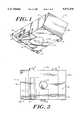
- FIG. 1is a perspective view of an augmentation system designed according to the present invention and intended to fit in a distal portion of a knee prosthesis femoral component.
- FIG. 2is an exploded view of the augmentation system illustrated in FIG. 1.
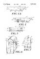
- FIG. 3is a top view of the augmentation system illustrated in FIG. 1.
- FIG. 4is a side view, from the medial or lateral side, of the augmentation system illustrated in FIG. 1.
- FIG. 4Ais a side view, from the medial or lateral side, of an alternative augmentation system having indented surface features.
- FIG. 5is a side view, from the anterior or posterior side, of the augmentation system illustrated in FIG. 1.
- FIG. 6is a perspective view of an alternative augmentation system according to the present invention designed to fit in a posterior portion of a knee prosthesis femoral component.
- FIG. 7is a side view, from the anterior or posterior side of the augmentation system illustrated in FIG. 6.
- FIG. 8is a side view, from the lateral or medial side, of the augmentation system of FIG. 6.
- FIG. 9illustrates the positioning of an augmentation system of the type shown in FIG. 1 within a distal portion of the femoral component of a knee prosthesis.
- FIG. 9Ais a sectional view of the augmentation system shown in FIG. 9, along lines A--A, showing the engagement of the augmentation system within a femoral component.
- FIG. 10illustrates the positioning of an augmentation system of the type shown in FIG. 6 within the posterior portion of the femoral component of a knee prosthesis.
- the augmentation system 10includes a main augmentation block 12 within which is disposed a channel 18.
- a secondary augmentation block 14is disposed within channel 18 and includes a screw 16 or similar device to adjust the position of the secondary augmentation block 14 with respect to the main augmentation block 12.
- the augmentation systemincludes a removable plug 20 disposed within an aperture 34 of the main augmentation block.
- Plug 20 and aperture 34enable the augmentation system 10 of the invention to be used with both cruciate sacrificing and cruciate retaining knee femoral components.
- the plug 20remains secure within aperture 34.
- the plug 20is removed from main block 12 and pegs 58 can be inserted through the aperture 34, as shown in FIG. 9.
- the augmentation system 10 of the present inventionis able to be used, without modification, in either left or right side knee prostheses.
- the main block 12 of the augmentation system 10has a proximal surface 28 and nominal distal surface 30.
- the area of the proximal surface 28is preferably greater than the area of the nominal distal surface 30.
- First and second side surfaces 24a, 24b of the main block 12can be anterior or posterior surfaces, depending upon whether the augmentation system is used with a left or right side prosthesis.
- first and second side surfaces 24a, 24bare canted such that each of the first and second side surfaces slope inwardly from the proximal surface 28 to the nominal distal surface 30 as shown in FIG. 4.
- the angle of the first and second side surfaces 24a, 24bcan vary as will be appreciated by those having ordinary skill in the art. As shown in FIG. 9, the angle of these surfaces corresponds to the angles of the anterior and posterior chamfers 52, 54 of a femoral component to enable proper seating of the augmentation system 10 within a femoral component.
- the third and fourth side surfaces 26a, 26b of the augmentation system 10correspond to either medial or lateral facing surfaces, depending upon whether the augmentation system is used in a left or right side knee prosthesis.
- Side surfaces 26a, 26bpreferably are substantially vertical.
- channel 18extends into the main block 12 through one of the side surfaces of the main block.
- the channel 18extends through one of the third or fourth side surfaces, 26a 26b.
- the channel 18can assume virtually any desired shape, but in a preferred embodiment, illustrated in FIGS. 1, 2 and 3, the channel is generally L-shaped.
- the channel 18may extend into the main block 12 between the proximal 28 and nominal distal surfaces 30 of the main block.
- the channel 18extends into the main block 12 such that it forms a cutout 35 of the actual distal surface 36 of the main block 12. In this embodiment the actual distal surface 36 and the distal surface 38 of secondary block 14 together form the nominal distal surface 30 the main block 12.
- Secondary block 14is configured and dimensioned to adjustably fit within channel 18.
- a threaded screw 16 or similar adjusting deviceis positioned within the threaded bore 40 of the secondary block 14. Adjustment of the screw 16 causes the distal end of the screw to abut the end wall (not shown) of channel 18. Further manipulation of the screw 16 in the same direction causes the secondary block 14 to move away from the main block 12, effectively increasing the overall width of the augmentation system 10. Manipulation of the screw 16 in the opposite direction causes the secondary block 14 to move back towards the main block 12, decreasing the overall width of the augmentation system 10.
- the secondary block 14includes a side surface 32 which corresponds in shape and orientation to the side surface of the main block 12 through which the channel 18 extends.
- the side surface 32 of the secondary blockcan be substantially flush with one of the side surfaces of the main block 12, such as third or fourth side surface 26a, 26b.
- the main block 12preferably includes at least one surface feature 22 disposed on at least one of the side surfaces of the main block.
- the surface featuresare disposed on at least one of the third or fourth side surfaces 26a, 26b.
- two surface features 22are disposed on either of the third or fourth side surfaces 26a, 26b which is the side surface of the main block opposite the side surface through which channel 18 extends.
- a surface feature 22appears on the side surface 32 of secondary block 14.
- the surface featureswhich may be indentations or protrusions, are intended to cooperate with structures of a knee prosthesis femoral component in order to provide secure mounting of the augmentation system 10 within a femoral component.
- the number and placement of the surface featurescan be varied to optimize the fixture of the augmentation system 10 within a femoral component.
- the surface features 22can be indentations or protrusions.
- Indented surface features 22, shown in FIG. 4Acan extend into the structure, that is either the main block or the secondary block, in a non-angled manner or in an angled manner.
- the indentationscan be of varied dimensions, but preferably have a depth of about 1 to 2 mm and a length or diameter of approximately 1 to 2 mm.
- Protruding surface featurescan extend out from the structure in a non-angled manner or at an angled manner.
- a preferred angled protruded surface featureextends outwardly and distally of the structure.
- surface feature protrusionshave a length of about 1 to 2 mm and extend out from the structure by about 1 to 2 mm.
- Plug 20is removeably and replaceably positioned within aperture 34 of the main block 12.
- the plug 20can remain in or be removed from the augmentation system 10 depending upon whether the augmentation system is used with a cruciate retaining or a cruciate sacrificing femoral component of a knee prosthesis.
- the aperture 34preferably is circular in shape having a diameter of approximately 5 to 7 mm.
- the plug 20is of a corresponding shape and dimension so as to enable it to fit securely, in an interference fit, within aperture 34.
- the plug 20is made from ultra high molecular weight polyethylene or other suitable materials.
- FIGS. 6 through 8illustrate a configuration for an alternative augmentation system 110 of the present invention.
- This configuration systemis best suited for augmentation of a posterior portion of the femoral component of a knee prosthesis.
- the augmentation systemalso includes a main block 112 having a secondary block 114 mounted within a channel 118 that extends into the interior of the main block.
- a screw 116 or similar deviceextends into the secondary block 116 to control the positioning of the secondary block with respect to the main block.
- the alternative augmentation system 110illustrated in FIGS. 6 through 8, has a slightly different shape and surface configuration than does the main block 12 shown in FIGS. 1 through 5. As illustrated in FIG. 6 the proximal surface 128 of main block 112 is convex or dome-like while the distal surface 44 is canted.
- the distal surface 44is angled such that it extends downwardly from a shorter posterior side surface 46 to a longer anterior side surface 47.
- the angle of the distal surface 44should be substantially equivalent to the angle of the posterior chamfer 54 of a femoral component 50 upon which the distal surface 44 of the main block 112 is intended to seat.
- this anglecan be in the range of about 2° to 90° and is preferably about 45°.
- posterior side surface 46is slightly shorter than the anterior side surface 47.
- Posterior and anterior side surfaces 46, 47preferably are substantially vertical in orientation.
- the main block 12 of the alternative augmentation systemfurther includes third and fourth side surfaces 126a, 126b, which may be lateral or medial surfaces. Side surfaces 126a, 126b are substantially vertical in orientation.
- the secondary block 114 of augmentation system 110extends into the main block 114 through either of the side surfaces 126a, 126b, and is disposed within a channel (not shown) similar to channel 18.
- surface features 122may be used in connection with this embodiment of an augmentation block in a manner similar to that described above. Surface features 122 may be indentations or protrusions and share the same characteristics of and may be positioned similar to surface features 22 discussed above.
- FIGS. 9 and 9Aillustrate the positioning of augmentation system 10 within a femoral component 50 of a knee prosthesis.
- the femoral component 50is a cruciate retaining femoral component and includes pegs 58 which extend from the inferior surface of the lateral condyle 56 and the medial condyle 57.
- the femoral componentfurther includes an anterior chamfer 52 and a posterior chamfer 54.
- the plug 20Before mounting augmentation system 10 within a cruciate retaining femoral component 50, the plug 20 is removed from aperture 34. The augmentation system is then mounted by inserting the peg 58 which extends from the lateral condyle 56 through aperture 34. As so positioned, the nominal distal surface 30 of augmentation system 10 abuts the inferior surface of lateral condyle 56 while the posterior side surface 24a and the internal side surface 24b of the main augmentation block 12 abut the posterior chamfer and the anterior chamfer, respectively. As shown in FIG. 9A surface features 22 engage complementary structures 21 within femoral component 50 to secure the augmentation system in place. Manipulation of screw 16 can extend the secondary block 14 to an extent sufficient to ensure a secure fit for the augmentation system 10.
- FIG. 10illustrates the positioning of an augmentation system 110, which is intended for mounting in a posterior portion of a femoral component in order to allow for build up of the posterior inner condylar surfaces of a femoral component.
- the augmentation system 110is positioned against the inferior surfaces of posterior chamfer 54 and posterior flange or condyle 60.
- the distal surface 44 of main block 112abuts the posterior chamfer 54 while the posterior side surface 46 abuts the inferior surface of the posterior flange or condyle 60.
- the dimensions of the augmentation system of the inventioncan vary as required by the dimensions of the joint prostheses with which the system is to be used.
- One of ordinary skill in the artwill be able to determine the proper dimensions of the augmentation systems 10, 110 of the invention so as to closely fit the configuration of the interior of a femoral component with which it is used.
- the thickness (proximal to distal) of the augmentation systemis in the range of approximately 2 to 20 millimeters while the width (medial to lateral) ranges from about 10 mm to 40 mm and the length (anterior to posterior) ranges from about 10 mm to 60 mm.
- the augmentation system of the inventioncan be made from a variety of biocompatible materials having high strength, durability and resistance to wear debris.
- biocompatible materialshaving high strength, durability and resistance to wear debris.
- materialsinclude metal alloys such as cobalt chromium alloy, titanium vanadium alloy, stainless steel, ceramics and other materials that are well known for use in the manufacture of implantable bone prostheses.
- the augmentation system of the inventionoffers many advantages.
- the augmentation systemis able to be secured to knee prostheses components, without bone cement, in a secure fit such that relative motion between the joint prosthesis and augmentation system is relatively low or non-existent.
- This secure fitensures that the performance of the augmented prosthesis component is not compromised.
- the augmentation system of the inventioncan be easily attached within a joint prosthesis.
- the augmentation system of the inventioncan be used in left and right side joint prostheses without modification.
Landscapes
- Health & Medical Sciences (AREA)
- Orthopedic Medicine & Surgery (AREA)
- Cardiology (AREA)
- Oral & Maxillofacial Surgery (AREA)
- Transplantation (AREA)
- Engineering & Computer Science (AREA)
- Biomedical Technology (AREA)
- Heart & Thoracic Surgery (AREA)
- Vascular Medicine (AREA)
- Life Sciences & Earth Sciences (AREA)
- Animal Behavior & Ethology (AREA)
- General Health & Medical Sciences (AREA)
- Public Health (AREA)
- Veterinary Medicine (AREA)
- Physical Education & Sports Medicine (AREA)
- Prostheses (AREA)
Abstract
Description
This invention relates to a knee joint prosthesis, and more particularly to a prosthesis useful to augment bone deficiencies during knee arthroplasty procedures.
Knee arthroplasty is a well known surgical procedure by which a diseased and/or damaged natural knee joint is replaced by a prosthetic knee joint. In some instances, due to disease or trauma, insufficient healthy boney mass exists at the distal end of the femur to secure a femoral prostheses. It is thus necessary to remove a portion of the femur to ensure sufficient anchoring and a proper fit for the femoral prosthesis. In these instances, and in other cases, it is necessary to augment the inferior portion of the femoral component of the prosthesis to add additional thickness a prosthesis to compensate for a lack of sufficient boney tissue.
Augmentation of the boney mass can be accomplished by securing augmenting devices to the femoral component. Earlier techniques require that the augmenting devices be cemented to the inferior surface of the femoral component. Such techniques require accurate measurements and a great deal of precision since the augmenting device is difficult, if not impossible, to remove once it is secured to the prosthesis. These techniques do not allow sizing of the proper augmenting device by trial and error.
An improved augmentation technique is described in U.S. Pat. No. 4,936,847 (Manginelli). This patent describes an augmentation system that can be removeably and replaceably secured within a femoral component of a knee joint prosthesis. Such as design is advantageous because it avoids the need to cement augmenting devices to the inferior surface of the femoral component. As a result, augmenting devices of varying thicknesses can be fitted into place on the inferior surface of the femoral component. The augmenting devices can be removed and replaced with devices having different dimensions until the proper augmentation thickness is determined. Such an augmentation system, however, requires a specially constructed femoral component.
Despite existing augmentation systems, there remains a need to provide improved systems that allow standard augmenting components that can easily and securely be affixed within an existing femoral component. The cost of joint prostheses that utilize many current augmentation systems can be quite high due to the scrap rate and because prosthesis components, such as femoral components, must often be specially constructed to accommodate the augmenting devices. There is thus a need for an augmentation system that allows augmenting devices to be easily and securely fitted to standard prosthesis components.
It is thus an object of the invention to provide a femoral augmentation system that securely and easily fits within a femoral component of a knee joint prosthesis. Another object of the invention is to provide a femoral augmentation system that is compatible with standard femoral components of knee joint prostheses. It is also an object to provide an augmentation system that offers a great deal of versatility in that it can be used with different types of femoral components, including cruciate retaining and cruciate sacrificing femoral components. Other objects will be apparent to one of ordinary skill in the art upon reading the description that follows.
The present invention relates to a femoral augmentation system for use with knee joint prostheses. The system of the present invention serves to provide increased thickness to femoral components where boney deficiencies exist in a patient's femur.
The augmentation system of the invention includes a main augmenting block having a nominal distal surface and proximal surface. The main augmenting block also has first and second side surface that are either anterior or posterior surfaces, and third or fourth side surfaces that are either medial or lateral surfaces. The side surfaces of the main augmenting block can be of varying dimensions to provide desired thickness to the main augmenting block.
The main augmenting block also has at least one surface feature disposed on at least one of the side surfaces. The surface feature can be either an indentation or a protrusion formed in the side surface. Preferably, the surface feature is disposed on the third or fourth side surfaces, and there is present at least one surface feature on or associated with an opposite side surface.
The main augmenting block also includes a channel that extends into an interior portion thereof through one of the side surfaces. The channel is dimensioned to securely fit a secondary block component that is adjustably positioned within the channel. The secondary block component is adapted to be adjusted to secure the augmentation device within a joint prosthesis by an interference fit. The secondary block component preferably includes a side surface that corresponds in shape and orientation to the side surface of the main block through which the channel extends. A screw device is associated with the secondary block component, extending therethrough to effect adjustment of the position of the secondary block means relative to the main augmenting block.
In one embodiment a substantially centrally disposed aperture extends through the main augmenting block from the nominal distal surface to the proximal surface. A removable plug is preferably disposed within the aperture of the main augmenting block, in an interference fit.
The augmenting system of the invention is advantageous because it is able to fit securely within standard designs of knee prostheses femoral components. The augmentation system is used by positioning the system at a suitable location on the inferior surface of a femoral component. The screw that extends into the secondary block component can be used to expand (or contract) the secondary block, relative to the main block, thus changing the overall width of the augmentation device such that the augmentation device securely fits within the femoral component. By so doing, any surface features present on the main augmenting block engage the surface of the femoral component or complimentary surface features of the femoral component, to create a secure interference fit.
The "nominal distal surface" is defined herein as the entire surface area of the distal surface of the main augmenting block if the channel positioned within the main augmenting block does not form a cutout within the distal surface. If the channel does form a cutout of the portion of the distal surface of the main block, the "nominal distal surface" is defined to include the entire distal surface of the main block as well as the cutout portion of the distal surface of the main block.
For a further understanding of the nature and objects of the invention, reference should be made to the following detailed description of the invention and to the accompanying drawings, in which:
FIG. 1 is a perspective view of an augmentation system designed according to the present invention and intended to fit in a distal portion of a knee prosthesis femoral component.
FIG. 2 is an exploded view of the augmentation system illustrated in FIG. 1.
FIG. 3 is a top view of the augmentation system illustrated in FIG. 1.
FIG. 4 is a side view, from the medial or lateral side, of the augmentation system illustrated in FIG. 1.
FIG. 4A is a side view, from the medial or lateral side, of an alternative augmentation system having indented surface features.
FIG. 5 is a side view, from the anterior or posterior side, of the augmentation system illustrated in FIG. 1.
FIG. 6 is a perspective view of an alternative augmentation system according to the present invention designed to fit in a posterior portion of a knee prosthesis femoral component.
FIG. 7 is a side view, from the anterior or posterior side of the augmentation system illustrated in FIG. 6.
FIG. 8 is a side view, from the lateral or medial side, of the augmentation system of FIG. 6.
FIG. 9 illustrates the positioning of an augmentation system of the type shown in FIG. 1 within a distal portion of the femoral component of a knee prosthesis.
FIG. 9A is a sectional view of the augmentation system shown in FIG. 9, along lines A--A, showing the engagement of the augmentation system within a femoral component.
FIG. 10 illustrates the positioning of an augmentation system of the type shown in FIG. 6 within the posterior portion of the femoral component of a knee prosthesis.
As illustrated in FIGS. 1 and 2, theaugmentation system 10 includes amain augmentation block 12 within which is disposed achannel 18. Asecondary augmentation block 14 is disposed withinchannel 18 and includes ascrew 16 or similar device to adjust the position of thesecondary augmentation block 14 with respect to themain augmentation block 12. Surface features 22, which may be protrusions or indentations, preferably are disposed on one or more surfaces of themain augmentation block 12 or thesecondary augmentation block 14.
In one embodiment the augmentation system includes aremovable plug 20 disposed within anaperture 34 of the main augmentation block.Plug 20 andaperture 34 enable theaugmentation system 10 of the invention to be used with both cruciate sacrificing and cruciate retaining knee femoral components. When theaugmentation system 10 is used with a cruciate sacrificing femoral component, theplug 20 remains secure withinaperture 34. When theaugmentation system 10 of the invention is used with a cruciate retaining femoral component, theplug 20 is removed frommain block 12 and pegs 58 can be inserted through theaperture 34, as shown in FIG. 9.
Theaugmentation system 10 of the present invention is able to be used, without modification, in either left or right side knee prostheses. As shown in FIGS. 3 through 5, themain block 12 of theaugmentation system 10 has aproximal surface 28 and nominaldistal surface 30. The area of theproximal surface 28 is preferably greater than the area of the nominaldistal surface 30.
First andsecond side surfaces main block 12 can be anterior or posterior surfaces, depending upon whether the augmentation system is used with a left or right side prosthesis. Preferably, first andsecond side surfaces proximal surface 28 to the nominaldistal surface 30 as shown in FIG. 4. The angle of the first andsecond side surfaces posterior chamfers augmentation system 10 within a femoral component.
The third andfourth side surfaces augmentation system 10 correspond to either medial or lateral facing surfaces, depending upon whether the augmentation system is used in a left or right side knee prosthesis.Side surfaces
As illustrated,channel 18 extends into themain block 12 through one of the side surfaces of the main block. Preferably, thechannel 18 extends through one of the third or fourth side surfaces,26a 26b. Thechannel 18 can assume virtually any desired shape, but in a preferred embodiment, illustrated in FIGS. 1, 2 and 3, the channel is generally L-shaped. Thechannel 18 may extend into themain block 12 between the proximal 28 and nominaldistal surfaces 30 of the main block. Alternatively, as illustrated in FIG. 2, thechannel 18 extends into themain block 12 such that it forms a cutout 35 of the actualdistal surface 36 of themain block 12. In this embodiment the actualdistal surface 36 and thedistal surface 38 ofsecondary block 14 together form the nominaldistal surface 30 themain block 12.
Thesecondary block 14 includes a side surface 32 which corresponds in shape and orientation to the side surface of themain block 12 through which thechannel 18 extends. Thus, in one configuration the side surface 32 of the secondary block can be substantially flush with one of the side surfaces of themain block 12, such as third orfourth side surface
Themain block 12 preferably includes at least onesurface feature 22 disposed on at least one of the side surfaces of the main block. In one embodiment the surface features are disposed on at least one of the third orfourth side surfaces fourth side surfaces channel 18 extends. In this configuration asurface feature 22 appears on the side surface 32 ofsecondary block 14. The surface features, which may be indentations or protrusions, are intended to cooperate with structures of a knee prosthesis femoral component in order to provide secure mounting of theaugmentation system 10 within a femoral component. Thus, one of ordinary skill in the art will appreciate that the number and placement of the surface features can be varied to optimize the fixture of theaugmentation system 10 within a femoral component.
As noted above, the surface features 22 can be indentations or protrusions. Indented surface features 22, shown in FIG. 4A, can extend into the structure, that is either the main block or the secondary block, in a non-angled manner or in an angled manner. Preferably, the indentations can be of varied dimensions, but preferably have a depth of about 1 to 2 mm and a length or diameter of approximately 1 to 2 mm. Protruding surface features can extend out from the structure in a non-angled manner or at an angled manner. A preferred angled protruded surface feature extends outwardly and distally of the structure. Preferably, surface feature protrusions have a length of about 1 to 2 mm and extend out from the structure by about 1 to 2 mm.
FIGS. 6 through 8 illustrate a configuration for analternative augmentation system 110 of the present invention. This configuration system is best suited for augmentation of a posterior portion of the femoral component of a knee prosthesis.
In this embodiment, the augmentation system also includes amain block 112 having asecondary block 114 mounted within a channel 118 that extends into the interior of the main block. Ascrew 116 or similar device extends into thesecondary block 116 to control the positioning of the secondary block with respect to the main block.
Thealternative augmentation system 110, illustrated in FIGS. 6 through 8, has a slightly different shape and surface configuration than does themain block 12 shown in FIGS. 1 through 5. As illustrated in FIG. 6 the proximal surface 128 ofmain block 112 is convex or dome-like while thedistal surface 44 is canted.
Preferably, thedistal surface 44 is angled such that it extends downwardly from a shorterposterior side surface 46 to a longer anterior side surface 47. The angle of thedistal surface 44 should be substantially equivalent to the angle of theposterior chamfer 54 of afemoral component 50 upon which thedistal surface 44 of themain block 112 is intended to seat. One of ordinary skill in the art will appreciate that this angle can be in the range of about 2° to 90° and is preferably about 45°.
As noted above, theposterior side surface 46 is slightly shorter than the anterior side surface 47. Posterior and anterior side surfaces 46, 47 preferably are substantially vertical in orientation.
Themain block 12 of the alternative augmentation system further includes third andfourth side surfaces Side surfaces
Thesecondary block 114 ofaugmentation system 110 extends into themain block 114 through either of theside surfaces channel 18. In addition, surface features 122 may be used in connection with this embodiment of an augmentation block in a manner similar to that described above. Surface features 122 may be indentations or protrusions and share the same characteristics of and may be positioned similar to surface features 22 discussed above.
FIGS. 9 and 9A illustrate the positioning ofaugmentation system 10 within afemoral component 50 of a knee prosthesis. In the illustrated embodiment thefemoral component 50 is a cruciate retaining femoral component and includespegs 58 which extend from the inferior surface of thelateral condyle 56 and themedial condyle 57. The femoral component further includes ananterior chamfer 52 and aposterior chamfer 54.
Before mountingaugmentation system 10 within a cruciate retainingfemoral component 50, theplug 20 is removed fromaperture 34. The augmentation system is then mounted by inserting thepeg 58 which extends from thelateral condyle 56 throughaperture 34. As so positioned, the nominaldistal surface 30 ofaugmentation system 10 abuts the inferior surface oflateral condyle 56 while theposterior side surface 24a and theinternal side surface 24b of themain augmentation block 12 abut the posterior chamfer and the anterior chamfer, respectively. As shown in FIG. 9A surface features 22 engagecomplementary structures 21 withinfemoral component 50 to secure the augmentation system in place. Manipulation ofscrew 16 can extend thesecondary block 14 to an extent sufficient to ensure a secure fit for theaugmentation system 10.
FIG. 10 illustrates the positioning of anaugmentation system 110, which is intended for mounting in a posterior portion of a femoral component in order to allow for build up of the posterior inner condylar surfaces of a femoral component.
As illustrated, theaugmentation system 110 is positioned against the inferior surfaces ofposterior chamfer 54 and posterior flange orcondyle 60. Thedistal surface 44 ofmain block 112 abuts theposterior chamfer 54 while theposterior side surface 46 abuts the inferior surface of the posterior flange orcondyle 60.
The dimensions of the augmentation system of the invention can vary as required by the dimensions of the joint prostheses with which the system is to be used. One of ordinary skill in the art will be able to determine the proper dimensions of theaugmentation systems
The augmentation system of the invention can be made from a variety of biocompatible materials having high strength, durability and resistance to wear debris. Examples of such materials include metal alloys such as cobalt chromium alloy, titanium vanadium alloy, stainless steel, ceramics and other materials that are well known for use in the manufacture of implantable bone prostheses.
The augmentation system of the invention offers many advantages. For example, the augmentation system is able to be secured to knee prostheses components, without bone cement, in a secure fit such that relative motion between the joint prosthesis and augmentation system is relatively low or non-existent. This secure fit ensures that the performance of the augmented prosthesis component is not compromised. Moreover, the augmentation system of the invention can be easily attached within a joint prosthesis. Of particular significance is the fact that the augmentation system of the invention can be used in left and right side joint prostheses without modification.
The foregoing description of the illustrative embodiment of the invention is presented to indicate the range of constructions to which the invention applies. Variations in the physical architecture and dimensions of the augmentation system will be apparent to those having ordinary skill in the art based upon the disclosure herein, and such variations are considered to be within the scope of the invention in which patent rights are asserted, as set forth in the claims appended hereto.
Claims (21)
1. An augmentation device for a joint prosthesis; comprising
a main augmenting block adapted to mount on a surface of a joint prosthesis, the main augmenting block having a nominal distal surface and a proximal surface, first and second side surfaces that are either anterior or posterior surfaces, and third and fourth side surfaces that are either medial or lateral surfaces;
a channel disposed in the main augmenting block and extending into an interior portion of the main augmenting block through one of the side surfaces of the main augmenting block;
a secondary block means, adjustably positioned within the channel of the main augmenting block, for securing the augmentation device to a joint prosthesis, the secondary block means including a side surface that is either a lateral or medial surface and that corresponds in shape and orientation to the side surface of the main augmenting block through which the channel extends; and
screw means associated with the secondary block means fog adjusting the position of the secondary block means relative to the main augmenting block between at least a first and a second position.
2. The device of claim 1 further including at least one surface feature selected from the group consisting of indentations and protrusions, said at least one surface feature being disposed on at least one of the side surfaces of the main block and being adapted to cooperate with a component of a joint prosthesis to secure the augmentation device to the joint prosthesis.
3. The device of claim 1 wherein the nominal distal surface of the main augmenting block has an area that is less than that of the proximal surface.
4. The device of claim 3 wherein the first and second side surfaces of the main augmenting block are canted.
5. The device of claim 2 wherein at least one surface feature is disposed on each of the third and fourth side surfaces of the main augmenting block.
6. The device of claim 2 wherein at least one surface feature is disposed on each of the first and second side surfaces of the main augmenting block.
7. The device of claim 2 wherein at least one surface feature is disposed on the side surface of the main augmenting block opposite the side surface of the main augmenting block through which the channel extends.
8. The device of claim 2 wherein at least one surface feature is disposed on the side surface of the main augmenting block opposite to the side surface of the main augmenting block through which the channel extends.
9. The device of claim 2 wherein at least one surface feature is disposed on the side surface of the secondary block means.
10. The device of claim 2 wherein the surface feature is a protrusion that extends outwardly and distally.
11. The device of claim 2 wherein the surface feature is an indentation that extends inwardly and proximally.
12. The device of claim 1 wherein the channel is open to the distal surface of the main augmenting block.
13. The device of claim 1 wherein the screw means extends into the interior of the secondary block means and is oriented substantially parallel to a medial-lateral plane of the main augmenting block.
14. The device of claim 1 wherein the device is able to be secured within a left or right side joint prosthesis.
15. The device of claim 14 wherein the joint prosthesis is a femoral component of an artificial knee joint.
16. The device of claim 1 further including a substantially centrally disposed aperture that extends from the nominal distal surface to the proximal surface.
17. The device of claim 16 further including a removable plug means for occluding the aperture, the plug means being disposed, in an interference fit, within the aperture of the main augmenting block.
18. The device of claim 1 wherein the first side surface is a posterior surface and the second side surface is an anterior surface having a length greater than the posterior surface.
19. The device of claim 18 wherein the proximal surface is of a convex, dome-like shape and is disposed opposite a .distal surface that is angled from a distal end of the posterior surface to a distal end of the anterior surface.
20. A joint prosthesis, comprising
a prosthesis component having a bone engaging surface and an opposed articulation surface;
a main augmenting block adapted to mount upon the bone engaging surface of the prosthesis component, the main augmenting block having a nominal distal surface which contacts the bone engaging surface and a proximal surface, first and second side surfaces that are either anterior or posterior surfaces, and third and fourth surfaces that are either medial or lateral surfaces;
a channel disposed in the main augmenting block and extending into an interior portion of the main augmenting block through one of the side surfaces of the main augmenting block;
a secondary block means, adjustably positioned within the channel of the main augmenting block, for securing the augmentation device to a joint prosthesis, the secondary block means including a side surface that is either a lateral or medial surface and that corresponds in shape and orientation to the side surface of the main augmenting block through which the channel extends; and
screw means associated with the secondary block means for adjusting the position of the secondary block means relative to the main augmenting block.
21. The joint prosthesis of claim 20 wherein the prosthesis component is a femoral component of a knee joint prosthesis.
Priority Applications (1)
| Application Number | Priority Date | Filing Date | Title |
|---|---|---|---|
| US08/339,019US5571194A (en) | 1994-11-14 | 1994-11-14 | Femoral augmentation system for artificial knee joint |
Applications Claiming Priority (1)
| Application Number | Priority Date | Filing Date | Title |
|---|---|---|---|
| US08/339,019US5571194A (en) | 1994-11-14 | 1994-11-14 | Femoral augmentation system for artificial knee joint |
Publications (1)
| Publication Number | Publication Date |
|---|---|
| US5571194Atrue US5571194A (en) | 1996-11-05 |
Family
ID=23327111
Family Applications (1)
| Application Number | Title | Priority Date | Filing Date |
|---|---|---|---|
| US08/339,019Expired - LifetimeUS5571194A (en) | 1994-11-14 | 1994-11-14 | Femoral augmentation system for artificial knee joint |
Country Status (1)
| Country | Link |
|---|---|
| US (1) | US5571194A (en) |
Cited By (69)
| Publication number | Priority date | Publication date | Assignee | Title |
|---|---|---|---|---|
| US5755800A (en)* | 1996-12-23 | 1998-05-26 | Johnson & Johnson Professional, Inc. | Modular joint prosthesis augmentation system |
| EP0898946A1 (en)* | 1997-08-29 | 1999-03-03 | Stratec Medical S.A. | Humeral head prosthesis |
| EP0941719A3 (en)* | 1998-03-10 | 2001-09-05 | Bristol-Myers Company | Four compartment knee |
| EP1374804A3 (en)* | 2002-06-18 | 2004-04-07 | Zimmer Technology, Inc. | Porous unicondylar knee prosthesis |
| US20040075731A1 (en)* | 2002-10-18 | 2004-04-22 | Eastman Kodak Company | Method and apparatus for reducing uneven use of heating elements on thermal print head |
| US20050075736A1 (en)* | 2003-10-03 | 2005-04-07 | Howmedica Osteonics Corp. | Expandable augment trial |
| US7445639B2 (en) | 2001-02-23 | 2008-11-04 | Biomet Manufacturing Corp. | Knee joint prosthesis |
| US20090043396A1 (en)* | 2006-03-21 | 2009-02-12 | Komistek Richard D | Moment induced total arthroplasty prosthetic |
| US7497874B1 (en) | 2001-02-23 | 2009-03-03 | Biomet Manufacturing Corp. | Knee joint prosthesis |
| WO2009089581A1 (en)* | 2008-01-18 | 2009-07-23 | Atlax Pty Ltd | An augment for use in a knee replacement system and method of performing a knee replacement operation |
| US7597715B2 (en) | 2005-04-21 | 2009-10-06 | Biomet Manufacturing Corp. | Method and apparatus for use of porous implants |
| US7635447B2 (en) | 2006-02-17 | 2009-12-22 | Biomet Manufacturing Corp. | Method and apparatus for forming porous metal implants |
| US20090326665A1 (en)* | 2008-06-30 | 2009-12-31 | Wyss Joseph G | Posterior stabilized orthopaedic knee prosthesis having controlled condylar curvature |
| US20090326664A1 (en)* | 2008-06-30 | 2009-12-31 | Wagner Christel M | Posterior cructiate-retaining orthopaedic knee prosthesis having controlled condylar curvature |
| US20090326667A1 (en)* | 2008-06-30 | 2009-12-31 | Williams John L | Orthopaedic femoral component having controlled condylar curvature |
| US20100016978A1 (en)* | 2008-07-16 | 2010-01-21 | Depuy Products, Inc. | Antero-posterior placement of axis of rotation for a rotating platform |
| US20100016979A1 (en)* | 2008-07-16 | 2010-01-21 | Depuy Products, Inc. | Knee prostheses with enhanced kinematics |
| US20100036500A1 (en)* | 2008-06-30 | 2010-02-11 | Heldreth Mark A | Orthopaedic knee prosthesis having controlled condylar curvature |
| US20100217399A1 (en)* | 2009-02-22 | 2010-08-26 | Groh Gordon I | Base plate system for shoulder arthroplasty and method of using the same |
| US7799084B2 (en) | 2002-10-23 | 2010-09-21 | Mako Surgical Corp. | Modular femoral component for a total knee joint replacement for minimally invasive implantation |
| US20100286788A1 (en)* | 2009-05-07 | 2010-11-11 | Richard David Komistek | Anterior stabilized knee implant |
| US8021432B2 (en) | 2005-12-05 | 2011-09-20 | Biomet Manufacturing Corp. | Apparatus for use of porous implants |
| US8066778B2 (en) | 2005-04-21 | 2011-11-29 | Biomet Manufacturing Corp. | Porous metal cup with cobalt bearing surface |
| US8123814B2 (en) | 2001-02-23 | 2012-02-28 | Biomet Manufacturing Corp. | Method and appartus for acetabular reconstruction |
| US8157869B2 (en) | 2007-01-10 | 2012-04-17 | Biomet Manufacturing Corp. | Knee joint prosthesis system and method for implantation |
| US8163028B2 (en) | 2007-01-10 | 2012-04-24 | Biomet Manufacturing Corp. | Knee joint prosthesis system and method for implantation |
| WO2012021702A3 (en)* | 2010-08-12 | 2012-05-03 | Smith & Nephew, Inc. | Structures for use in orthopaedic implant fixation and methods of installation onto a bone |
| US8187280B2 (en) | 2007-10-10 | 2012-05-29 | Biomet Manufacturing Corp. | Knee joint prosthesis system and method for implantation |
| US8206451B2 (en) | 2008-06-30 | 2012-06-26 | Depuy Products, Inc. | Posterior stabilized orthopaedic prosthesis |
| US8266780B2 (en) | 2005-04-21 | 2012-09-18 | Biomet Manufacturing Corp. | Method and apparatus for use of porous implants |
| US8292967B2 (en) | 2005-04-21 | 2012-10-23 | Biomet Manufacturing Corp. | Method and apparatus for use of porous implants |
| US8328873B2 (en) | 2007-01-10 | 2012-12-11 | Biomet Manufacturing Corp. | Knee joint prosthesis system and method for implantation |
| US8562616B2 (en) | 2007-10-10 | 2013-10-22 | Biomet Manufacturing, Llc | Knee joint prosthesis system and method for implantation |
| US8603101B2 (en) | 2010-12-17 | 2013-12-10 | Zimmer, Inc. | Provisional tibial prosthesis system |
| EP2682073A1 (en)* | 2012-07-02 | 2014-01-08 | DePuy (Ireland) | Knee prosthesis system with side-mounted augments |
| US8900316B2 (en) | 2010-01-29 | 2014-12-02 | Smith & Nephew, Inc. | Cruciate-retaining knee prosthesis |
| US8961612B2 (en) | 2012-08-30 | 2015-02-24 | Biomet Manufacturing, Llc | Knee component having orbital interface boss |
| US9119723B2 (en) | 2008-06-30 | 2015-09-01 | Depuy (Ireland) | Posterior stabilized orthopaedic prosthesis assembly |
| US9149206B2 (en) | 2012-03-30 | 2015-10-06 | Zimmer, Inc. | Tibial prosthesis systems, kits, and methods |
| US9168145B2 (en) | 2008-06-30 | 2015-10-27 | Depuy (Ireland) | Posterior stabilized orthopaedic knee prosthesis having controlled condylar curvature |
| US9492280B2 (en) | 2000-11-28 | 2016-11-15 | Medidea, Llc | Multiple-cam, posterior-stabilized knee prosthesis |
| US9592133B2 (en) | 2013-09-23 | 2017-03-14 | Zimmer, Inc. | Spacer block |
| US9597090B2 (en) | 2010-12-17 | 2017-03-21 | Zimmer, Inc. | Cut guide attachment for use in tibial prosthesis systems |
| US20170333208A1 (en)* | 2016-05-18 | 2017-11-23 | Depuy Ireland Unlimited Company | System including femoral augment trials and method of performing an orthopaedic joint replacement procedure |
| WO2018095778A3 (en)* | 2016-11-24 | 2018-09-27 | Waldemar Link Gmbh & Co. Kg | Intermediate segment for a joint component |
| US10130480B2 (en) | 2013-03-13 | 2018-11-20 | Howmedica Osteonics Corp. | Modular patella trials |
| US10179052B2 (en) | 2016-07-28 | 2019-01-15 | Depuy Ireland Unlimited Company | Total knee implant prosthesis assembly and method |
| US10195041B2 (en) | 2010-07-24 | 2019-02-05 | Zimmer, Inc. | Asymmetric tibial components for a knee prosthesis |
| US10265181B2 (en) | 2011-11-21 | 2019-04-23 | Zimmer, Inc. | Tibial baseplate with asymmetric placement of fixation structures |
| US10278827B2 (en) | 2015-09-21 | 2019-05-07 | Zimmer, Inc. | Prosthesis system including tibial bearing component |
| US10413415B2 (en) | 2010-09-10 | 2019-09-17 | Zimmer, Inc. | Motion facilitating tibial components for a knee prosthesis |
| US10470889B2 (en) | 2010-07-24 | 2019-11-12 | Zimmer, Inc. | Asymmetric tibial components for a knee prosthesis |
| US10470899B2 (en) | 2016-05-18 | 2019-11-12 | Depuy Ireland Unlimited Company | Method for preparing a patient's tibia in an orthopaedic joint replacement procedure |
| US10537446B2 (en) | 2017-09-20 | 2020-01-21 | Depuy Ireland Unlimited Company | Method and instruments for assembling an orthopaedic prosthesis |
| US10537341B2 (en) | 2017-09-20 | 2020-01-21 | Depuy Ireland Unlimited Company | Orthopaedic system and method for assembling prosthetic components |
| US10543001B2 (en) | 2017-09-20 | 2020-01-28 | Depuy Ireland Unlimited Company | Method and instruments for assembling a femoral orthopaedic prosthesis |
| US10543099B2 (en) | 2010-07-24 | 2020-01-28 | Zimmer, Inc. | Tibial prosthesis |
| US10675153B2 (en) | 2017-03-10 | 2020-06-09 | Zimmer, Inc. | Tibial prosthesis with tibial bearing component securing feature |
| US10835380B2 (en) | 2018-04-30 | 2020-11-17 | Zimmer, Inc. | Posterior stabilized prosthesis system |
| US10898337B2 (en) | 2011-11-18 | 2021-01-26 | Zimmer, Inc. | Tibial bearing component for a knee prosthesis with improved articular characteristics |
| US11065124B2 (en) | 2018-05-25 | 2021-07-20 | Howmedica Osteonics Corp. | Variable thickness femoral augments |
| US11083585B2 (en) | 2019-05-09 | 2021-08-10 | Howmedica Osteonics Corp. | Spring retained femoral augment |
| US11324599B2 (en) | 2017-05-12 | 2022-05-10 | Zimmer, Inc. | Femoral prostheses with upsizing and downsizing capabilities |
| US11324598B2 (en) | 2013-08-30 | 2022-05-10 | Zimmer, Inc. | Method for optimizing implant designs |
| US20220226002A1 (en)* | 2019-07-05 | 2022-07-21 | Jonathan Peter Cabot | Arrangement and method used in the preparation of bone surfaces of the knee joint for the components of a prosthetic knee joint |
| US11426282B2 (en) | 2017-11-16 | 2022-08-30 | Zimmer, Inc. | Implants for adding joint inclination to a knee arthroplasty |
| US11439409B2 (en) | 2019-09-18 | 2022-09-13 | Depuy Ireland Unlimited Company | Cutting block |
| US11491013B2 (en) | 2019-07-11 | 2022-11-08 | Howmedica Osteonics Corp. | Augment and means for connecting the same to a joint prosthesis |
| US12011371B2 (en) | 2016-05-18 | 2024-06-18 | Depuy Ireland Unlimited Company | System and method for surgically-preparing a patient's femur |
Citations (10)
| Publication number | Priority date | Publication date | Assignee | Title |
|---|---|---|---|---|
| US4778473A (en)* | 1983-11-28 | 1988-10-18 | The University Of Michigan | Prosthesis interface surface and method of implanting |
| GB2223174A (en)* | 1988-09-08 | 1990-04-04 | Bristol Myers Co | Prosthetic implant |
| US4936853A (en)* | 1989-01-11 | 1990-06-26 | Kirschner Medical Corporation | Modular knee prosthesis |
| US4936847A (en)* | 1988-12-27 | 1990-06-26 | Johnson & Johnson Orthopaedics, Inc. | Revision knee prosthesis |
| US4950298A (en)* | 1988-04-08 | 1990-08-21 | Gustilo Ramon B | Modular knee joint prosthesis |
| US5152796A (en)* | 1988-12-27 | 1992-10-06 | Johnson & Johnson Orthopaedics, Inc. | Modular knee prosthesis |
| US5201769A (en)* | 1991-09-23 | 1993-04-13 | Schutzer Steven F | Hip stem with proximal build-up blocks |
| US5222984A (en)* | 1990-03-15 | 1993-06-29 | Forte Mark R | Implantable acetabular prosthetic hip joint with universal adjustability |
| US5344461A (en)* | 1993-02-12 | 1994-09-06 | Zimmer, Inc. | Modular implant provisional |
| US5387241A (en)* | 1994-01-28 | 1995-02-07 | Zimmer, Inc. | Ribbed augment for a prosthetic implant |
- 1994
- 1994-11-14USUS08/339,019patent/US5571194A/ennot_activeExpired - Lifetime
Patent Citations (10)
| Publication number | Priority date | Publication date | Assignee | Title |
|---|---|---|---|---|
| US4778473A (en)* | 1983-11-28 | 1988-10-18 | The University Of Michigan | Prosthesis interface surface and method of implanting |
| US4950298A (en)* | 1988-04-08 | 1990-08-21 | Gustilo Ramon B | Modular knee joint prosthesis |
| GB2223174A (en)* | 1988-09-08 | 1990-04-04 | Bristol Myers Co | Prosthetic implant |
| US4936847A (en)* | 1988-12-27 | 1990-06-26 | Johnson & Johnson Orthopaedics, Inc. | Revision knee prosthesis |
| US5152796A (en)* | 1988-12-27 | 1992-10-06 | Johnson & Johnson Orthopaedics, Inc. | Modular knee prosthesis |
| US4936853A (en)* | 1989-01-11 | 1990-06-26 | Kirschner Medical Corporation | Modular knee prosthesis |
| US5222984A (en)* | 1990-03-15 | 1993-06-29 | Forte Mark R | Implantable acetabular prosthetic hip joint with universal adjustability |
| US5201769A (en)* | 1991-09-23 | 1993-04-13 | Schutzer Steven F | Hip stem with proximal build-up blocks |
| US5344461A (en)* | 1993-02-12 | 1994-09-06 | Zimmer, Inc. | Modular implant provisional |
| US5387241A (en)* | 1994-01-28 | 1995-02-07 | Zimmer, Inc. | Ribbed augment for a prosthetic implant |
Cited By (166)
| Publication number | Priority date | Publication date | Assignee | Title |
|---|---|---|---|---|
| EP0850608A3 (en)* | 1996-12-23 | 1998-12-16 | Johnson & Johnson Professional, Inc. | Modular joint prosthesis augmentation system |
| US5755800A (en)* | 1996-12-23 | 1998-05-26 | Johnson & Johnson Professional, Inc. | Modular joint prosthesis augmentation system |
| EP0898946A1 (en)* | 1997-08-29 | 1999-03-03 | Stratec Medical S.A. | Humeral head prosthesis |
| FR2767674A1 (en)* | 1997-08-29 | 1999-03-05 | Vecteur Orthopedic | PROSTHESIS OF THE SUPERIOR END OF THE HUMERUS |
| EP1518521A3 (en)* | 1998-03-10 | 2005-10-12 | Bristol-Myers Squibb Company | Four compartment knee |
| EP0941719A3 (en)* | 1998-03-10 | 2001-09-05 | Bristol-Myers Company | Four compartment knee |
| US6402786B1 (en)* | 1998-03-10 | 2002-06-11 | Zimmer, Inc. | Four compartment knee |
| US10188521B2 (en) | 2000-11-28 | 2019-01-29 | Medidea, Llc | Multiple-cam, posterior-stabilized knee prosthesis |
| US9492280B2 (en) | 2000-11-28 | 2016-11-15 | Medidea, Llc | Multiple-cam, posterior-stabilized knee prosthesis |
| US7445639B2 (en) | 2001-02-23 | 2008-11-04 | Biomet Manufacturing Corp. | Knee joint prosthesis |
| US8551181B2 (en) | 2001-02-23 | 2013-10-08 | Biomet Manufacturing, Llc | Method and apparatus for acetabular reconstruction |
| US9375316B2 (en) | 2001-02-23 | 2016-06-28 | Biomet Manufacturing, Llc. | Method and apparatus for acetabular reconstruction |
| US8123814B2 (en) | 2001-02-23 | 2012-02-28 | Biomet Manufacturing Corp. | Method and appartus for acetabular reconstruction |
| US7497874B1 (en) | 2001-02-23 | 2009-03-03 | Biomet Manufacturing Corp. | Knee joint prosthesis |
| US6797006B2 (en) | 2002-06-18 | 2004-09-28 | Zimmer Technology, Inc. | Porous unicondylar knee |
| EP1374804A3 (en)* | 2002-06-18 | 2004-04-07 | Zimmer Technology, Inc. | Porous unicondylar knee prosthesis |
| US20040075731A1 (en)* | 2002-10-18 | 2004-04-22 | Eastman Kodak Company | Method and apparatus for reducing uneven use of heating elements on thermal print head |
| US7799084B2 (en) | 2002-10-23 | 2010-09-21 | Mako Surgical Corp. | Modular femoral component for a total knee joint replacement for minimally invasive implantation |
| US20050075736A1 (en)* | 2003-10-03 | 2005-04-07 | Howmedica Osteonics Corp. | Expandable augment trial |
| US7547327B2 (en)* | 2003-10-03 | 2009-06-16 | Howmedica Osteonics Corp. | Expandable augment trial |
| US8197550B2 (en) | 2005-04-21 | 2012-06-12 | Biomet Manufacturing Corp. | Method and apparatus for use of porous implants |
| US7597715B2 (en) | 2005-04-21 | 2009-10-06 | Biomet Manufacturing Corp. | Method and apparatus for use of porous implants |
| US8266780B2 (en) | 2005-04-21 | 2012-09-18 | Biomet Manufacturing Corp. | Method and apparatus for use of porous implants |
| US8292967B2 (en) | 2005-04-21 | 2012-10-23 | Biomet Manufacturing Corp. | Method and apparatus for use of porous implants |
| US8066778B2 (en) | 2005-04-21 | 2011-11-29 | Biomet Manufacturing Corp. | Porous metal cup with cobalt bearing surface |
| US8021432B2 (en) | 2005-12-05 | 2011-09-20 | Biomet Manufacturing Corp. | Apparatus for use of porous implants |
| US7635447B2 (en) | 2006-02-17 | 2009-12-22 | Biomet Manufacturing Corp. | Method and apparatus for forming porous metal implants |
| US10045849B2 (en) | 2006-03-21 | 2018-08-14 | Depuy Ireland Unlimited Company | Moment induced total arthroplasty prosthetic |
| US20090043396A1 (en)* | 2006-03-21 | 2009-02-12 | Komistek Richard D | Moment induced total arthroplasty prosthetic |
| US10932915B2 (en) | 2006-03-21 | 2021-03-02 | Depuy Ireland Unlimited Company | Moment induced total arthroplasty prosthetic |
| US9254197B2 (en) | 2006-03-21 | 2016-02-09 | Depuy (Ireland) | Moment induced total arthroplasty prosthetic |
| US8636807B2 (en) | 2006-03-21 | 2014-01-28 | Depuy (Ireland) | Moment induced total arthroplasty prosthetic |
| US8163028B2 (en) | 2007-01-10 | 2012-04-24 | Biomet Manufacturing Corp. | Knee joint prosthesis system and method for implantation |
| US8157869B2 (en) | 2007-01-10 | 2012-04-17 | Biomet Manufacturing Corp. | Knee joint prosthesis system and method for implantation |
| US8328873B2 (en) | 2007-01-10 | 2012-12-11 | Biomet Manufacturing Corp. | Knee joint prosthesis system and method for implantation |
| US8936648B2 (en) | 2007-01-10 | 2015-01-20 | Biomet Manufacturing, Llc | Knee joint prosthesis system and method for implantation |
| US8480751B2 (en) | 2007-01-10 | 2013-07-09 | Biomet Manufacturing, Llc | Knee joint prosthesis system and method for implantation |
| US8187280B2 (en) | 2007-10-10 | 2012-05-29 | Biomet Manufacturing Corp. | Knee joint prosthesis system and method for implantation |
| US9763793B2 (en) | 2007-10-10 | 2017-09-19 | Biomet Manufacturing, Llc | Knee joint prosthesis system and method for implantation |
| US8562616B2 (en) | 2007-10-10 | 2013-10-22 | Biomet Manufacturing, Llc | Knee joint prosthesis system and method for implantation |
| US10736747B2 (en) | 2007-10-10 | 2020-08-11 | Biomet Manufacturing, Llc | Knee joint prosthesis system and method for implantation |
| US20110015751A1 (en)* | 2008-01-18 | 2011-01-20 | Lindsay Laird | Augment For Use In A Knee Prelacement System And Method Of Performing A Knee Replacement Operation |
| GB2469253A (en)* | 2008-01-18 | 2010-10-06 | Atlax Pty Ltd | An augment for use in a knee replacement system and method of performing a knee replacement operation |
| WO2009089581A1 (en)* | 2008-01-18 | 2009-07-23 | Atlax Pty Ltd | An augment for use in a knee replacement system and method of performing a knee replacement operation |
| US9168145B2 (en) | 2008-06-30 | 2015-10-27 | Depuy (Ireland) | Posterior stabilized orthopaedic knee prosthesis having controlled condylar curvature |
| US20090326665A1 (en)* | 2008-06-30 | 2009-12-31 | Wyss Joseph G | Posterior stabilized orthopaedic knee prosthesis having controlled condylar curvature |
| US8236061B2 (en) | 2008-06-30 | 2012-08-07 | Depuy Products, Inc. | Orthopaedic knee prosthesis having controlled condylar curvature |
| US8206451B2 (en) | 2008-06-30 | 2012-06-26 | Depuy Products, Inc. | Posterior stabilized orthopaedic prosthesis |
| US9937049B2 (en) | 2008-06-30 | 2018-04-10 | Depuy Ireland Unlimited Company | Orthopaedic knee prosthesis having controlled condylar curvature |
| US8192498B2 (en) | 2008-06-30 | 2012-06-05 | Depuy Products, Inc. | Posterior cructiate-retaining orthopaedic knee prosthesis having controlled condylar curvature |
| US9931216B2 (en) | 2008-06-30 | 2018-04-03 | Depuy Ireland Unlimited Company | Orthopaedic femoral component having controlled condylar curvature |
| US10849760B2 (en) | 2008-06-30 | 2020-12-01 | Depuy Ireland Unlimited Company | Orthopaedic knee prosthesis having controlled condylar curvature |
| US12109119B2 (en) | 2008-06-30 | 2024-10-08 | Depuy Ireland Unlimited Company | Orthopaedic femoral component having controlled condylar curvature |
| US8187335B2 (en) | 2008-06-30 | 2012-05-29 | Depuy Products, Inc. | Posterior stabilized orthopaedic knee prosthesis having controlled condylar curvature |
| US8734522B2 (en) | 2008-06-30 | 2014-05-27 | Depuy (Ireland) | Posterior stabilized orthopaedic prosthesis |
| US8784496B2 (en) | 2008-06-30 | 2014-07-22 | Depuy (Ireland) | Orthopaedic knee prosthesis having controlled condylar curvature |
| US8795380B2 (en) | 2008-06-30 | 2014-08-05 | Depuy (Ireland) | Orthopaedic knee prosthesis having controlled condylar curvature |
| US8828086B2 (en) | 2008-06-30 | 2014-09-09 | Depuy (Ireland) | Orthopaedic femoral component having controlled condylar curvature |
| US8834575B2 (en) | 2008-06-30 | 2014-09-16 | Depuy (Ireland) | Posterior stabilized orthopaedic knee prosthesis having controlled condylar curvature |
| US9452053B2 (en) | 2008-06-30 | 2016-09-27 | Depuy (Ireland) | Orthopaedic knee prosthesis having controlled condylar curvature |
| US20090326664A1 (en)* | 2008-06-30 | 2009-12-31 | Wagner Christel M | Posterior cructiate-retaining orthopaedic knee prosthesis having controlled condylar curvature |
| US10543098B2 (en) | 2008-06-30 | 2020-01-28 | Depuy Ireland Unlimited Company | Orthopaedic femoral component having controlled condylar curvature |
| US10265180B2 (en) | 2008-06-30 | 2019-04-23 | Depuy Ireland Unlimited Company | Orthopaedic knee prosthesis having controlled condylar curvature |
| US12059356B2 (en) | 2008-06-30 | 2024-08-13 | Depuy Ireland Unlimited Company | Orthopaedic knee prosthesis having controlled condylar curvature |
| US11730602B2 (en) | 2008-06-30 | 2023-08-22 | Depuy Ireland Unlimited Company | Orthopaedic knee prosthesis having controlled condylar curvature |
| US9119723B2 (en) | 2008-06-30 | 2015-09-01 | Depuy (Ireland) | Posterior stabilized orthopaedic prosthesis assembly |
| US20090326667A1 (en)* | 2008-06-30 | 2009-12-31 | Williams John L | Orthopaedic femoral component having controlled condylar curvature |
| US11337823B2 (en) | 2008-06-30 | 2022-05-24 | Depuy Ireland Unlimited Company | Orthopaedic femoral component having controlled condylar curvature |
| US9204968B2 (en) | 2008-06-30 | 2015-12-08 | Depuy (Ireland) | Posterior stabilized orthopaedic prosthesis |
| US9220601B2 (en) | 2008-06-30 | 2015-12-29 | Depuy (Ireland) | Orthopaedic femoral component having controlled condylar curvature |
| US9539099B2 (en) | 2008-06-30 | 2017-01-10 | Depuy Ireland Unlimited Company | Orthopaedic knee prosthesis having controlled condylar curvature |
| US9326864B2 (en) | 2008-06-30 | 2016-05-03 | Depuy (Ireland) | Orthopaedic knee prosthesis having controlled condylar curvature |
| US20100036500A1 (en)* | 2008-06-30 | 2010-02-11 | Heldreth Mark A | Orthopaedic knee prosthesis having controlled condylar curvature |
| US11369478B2 (en) | 2008-06-30 | 2022-06-28 | Depuy Ireland Unlimited Company | Orthopaedic knee prosthesis having controlled condylar curvature |
| US10179051B2 (en) | 2008-06-30 | 2019-01-15 | Depuy Ireland Unlimited Company | Orthopaedic knee prosthesis having controlled condylar curvature |
| US10729551B2 (en) | 2008-06-30 | 2020-08-04 | Depuy Ireland Unlimited Company | Orthopaedic knee prosthesis having controlled condylar curvature |
| US20100016979A1 (en)* | 2008-07-16 | 2010-01-21 | Depuy Products, Inc. | Knee prostheses with enhanced kinematics |
| US20100016978A1 (en)* | 2008-07-16 | 2010-01-21 | Depuy Products, Inc. | Antero-posterior placement of axis of rotation for a rotating platform |
| US7981159B2 (en) | 2008-07-16 | 2011-07-19 | Depuy Products, Inc. | Antero-posterior placement of axis of rotation for a rotating platform |
| US8202323B2 (en) | 2008-07-16 | 2012-06-19 | Depuy Products, Inc. | Knee prostheses with enhanced kinematics |
| US20100217399A1 (en)* | 2009-02-22 | 2010-08-26 | Groh Gordon I | Base plate system for shoulder arthroplasty and method of using the same |
| US11564800B2 (en) | 2009-05-07 | 2023-01-31 | Depuy Ireland Unlimited Company | Anterior stabilized knee implant |
| US9408703B2 (en) | 2009-05-07 | 2016-08-09 | Depuy (Ireland) | Anterior stabilized knee implant |
| US8915965B2 (en) | 2009-05-07 | 2014-12-23 | Depuy (Ireland) | Anterior stabilized knee implant |
| US10500055B2 (en) | 2009-05-07 | 2019-12-10 | Depuy Ireland Unlimited Company | Anterior stabilized knee implant |
| US20100286788A1 (en)* | 2009-05-07 | 2010-11-11 | Richard David Komistek | Anterior stabilized knee implant |
| US9962264B2 (en) | 2009-05-07 | 2018-05-08 | Depuy Ireland Unlimited Company | Anterior stabilized knee implant |
| US10952862B2 (en) | 2010-01-29 | 2021-03-23 | Smith & Nephew, Inc. | Cruciate-retaining knee prosthesis |
| US8900316B2 (en) | 2010-01-29 | 2014-12-02 | Smith & Nephew, Inc. | Cruciate-retaining knee prosthesis |
| US12150860B2 (en) | 2010-01-29 | 2024-11-26 | Smith & Nephew, Inc. | Cruciate-retaining knee prosthesis |
| US12239540B2 (en) | 2010-07-24 | 2025-03-04 | Zimmer, Inc. | Asymmetric tibial components for a knee prosthesis |
| US11224519B2 (en) | 2010-07-24 | 2022-01-18 | Zimmer, Inc. | Asymmetric tibial components for a knee prosthesis |
| US10543099B2 (en) | 2010-07-24 | 2020-01-28 | Zimmer, Inc. | Tibial prosthesis |
| US10195041B2 (en) | 2010-07-24 | 2019-02-05 | Zimmer, Inc. | Asymmetric tibial components for a knee prosthesis |
| US10470889B2 (en) | 2010-07-24 | 2019-11-12 | Zimmer, Inc. | Asymmetric tibial components for a knee prosthesis |
| CN103402462B (en)* | 2010-08-12 | 2016-09-07 | 史密夫和内修有限公司 | For the structure that orthopaedic implants is fixing |
| US8926709B2 (en) | 2010-08-12 | 2015-01-06 | Smith & Nephew, Inc. | Structures for use in orthopaedic implant fixation and methods of installation onto a bone |
| CN103402462A (en)* | 2010-08-12 | 2013-11-20 | 史密夫和内修有限公司 | Structures for use in orthopaedic implant fixation and methods of installation onto a bone |
| WO2012021702A3 (en)* | 2010-08-12 | 2012-05-03 | Smith & Nephew, Inc. | Structures for use in orthopaedic implant fixation and methods of installation onto a bone |
| US11471288B2 (en) | 2010-09-10 | 2022-10-18 | Zimmer, Inc. | Motion facilitating tibial components for a knee prosthesis |
| US10413415B2 (en) | 2010-09-10 | 2019-09-17 | Zimmer, Inc. | Motion facilitating tibial components for a knee prosthesis |
| US9763807B2 (en) | 2010-12-17 | 2017-09-19 | Zimmer, Inc. | Provisional tibial prosthesis system |
| US10188530B2 (en) | 2010-12-17 | 2019-01-29 | Zimmer, Inc. | Provisional tibial prosthesis system |
| US9427337B2 (en) | 2010-12-17 | 2016-08-30 | Zimmer, Inc. | Provisional tibial prosthesis system |
| US10010330B2 (en) | 2010-12-17 | 2018-07-03 | Zimmer, Inc. | Cut guide attachment for use in tibial prosthesis systems |
| US9011459B2 (en) | 2010-12-17 | 2015-04-21 | Zimmer, Inc. | Provisional tibial prosthesis system |
| US9597090B2 (en) | 2010-12-17 | 2017-03-21 | Zimmer, Inc. | Cut guide attachment for use in tibial prosthesis systems |
| US9539116B2 (en) | 2010-12-17 | 2017-01-10 | Zimmer, Inc. | User interface related to a surgical provisional |
| US8603101B2 (en) | 2010-12-17 | 2013-12-10 | Zimmer, Inc. | Provisional tibial prosthesis system |
| US10898337B2 (en) | 2011-11-18 | 2021-01-26 | Zimmer, Inc. | Tibial bearing component for a knee prosthesis with improved articular characteristics |
| US12383407B2 (en) | 2011-11-18 | 2025-08-12 | Zimmer, Inc. | Tibial bearing component for a knee prosthesis with improved articular characteristics |
| US10265181B2 (en) | 2011-11-21 | 2019-04-23 | Zimmer, Inc. | Tibial baseplate with asymmetric placement of fixation structures |
| US9149206B2 (en) | 2012-03-30 | 2015-10-06 | Zimmer, Inc. | Tibial prosthesis systems, kits, and methods |
| US9492290B2 (en) | 2012-03-30 | 2016-11-15 | Zimmer, Inc. | Tibial prosthesis systems, kits, and methods |
| EP2682073A1 (en)* | 2012-07-02 | 2014-01-08 | DePuy (Ireland) | Knee prosthesis system with side-mounted augments |
| US8632599B1 (en)* | 2012-07-02 | 2014-01-21 | Depuy (Ireland) | Knee prosthesis system with side-mounted augments |
| US10278825B2 (en) | 2012-08-30 | 2019-05-07 | Biomet Manufacturing, Llc | Knee component having orbital interface boss |
| US8961612B2 (en) | 2012-08-30 | 2015-02-24 | Biomet Manufacturing, Llc | Knee component having orbital interface boss |
| US10130480B2 (en) | 2013-03-13 | 2018-11-20 | Howmedica Osteonics Corp. | Modular patella trials |
| US11013606B2 (en) | 2013-03-13 | 2021-05-25 | Howmedica Osteonics Corp. | Modular patella trials |
| US11974924B2 (en) | 2013-03-13 | 2024-05-07 | Howmedica Osteonics Corp. | Modular patella trials |
| US11324598B2 (en) | 2013-08-30 | 2022-05-10 | Zimmer, Inc. | Method for optimizing implant designs |
| US9592133B2 (en) | 2013-09-23 | 2017-03-14 | Zimmer, Inc. | Spacer block |
| US9901331B2 (en) | 2013-09-23 | 2018-02-27 | Zimmer, Inc. | Spacer block |
| US11160659B2 (en) | 2015-09-21 | 2021-11-02 | Zimmer, Inc. | Prosthesis system including tibial bearing component |
| US10278827B2 (en) | 2015-09-21 | 2019-05-07 | Zimmer, Inc. | Prosthesis system including tibial bearing component |
| US11234841B2 (en) | 2016-05-18 | 2022-02-01 | Depuy Ireland Unlimited Company | System and method of performing a reaming operation on a patient's femur during an orthopaedic joint replacement procedure |
| US10470899B2 (en) | 2016-05-18 | 2019-11-12 | Depuy Ireland Unlimited Company | Method for preparing a patient's tibia in an orthopaedic joint replacement procedure |
| US12059361B2 (en) | 2016-05-18 | 2024-08-13 | Depuy Ireland Unlimited Company | System for preparing a patient's tibia in an orthopaedic joint replacement procedure |
| US10492799B2 (en) | 2016-05-18 | 2019-12-03 | Depuy Ireland Unlimited Company | System for preparing a patient's tibia in an orthopaedic joint replacement procedure |
| US11504251B2 (en) | 2016-05-18 | 2022-11-22 | Depuy Ireland Unlimited Company | System and method for preparing a patient's femur in an orthopaedic joint replacement procedure |
| US12011371B2 (en) | 2016-05-18 | 2024-06-18 | Depuy Ireland Unlimited Company | System and method for surgically-preparing a patient's femur |
| US11497620B2 (en) | 2016-05-18 | 2022-11-15 | Depuy Ireland Unlimited Company | System for preparing a patient's tibia in an orthopaedic joint replacement procedure |
| US20170333208A1 (en)* | 2016-05-18 | 2017-11-23 | Depuy Ireland Unlimited Company | System including femoral augment trials and method of performing an orthopaedic joint replacement procedure |
| US10470898B2 (en) | 2016-05-18 | 2019-11-12 | Depuy Ireland Unlimited Company | Orthopaedic instrument system for surgically-preparing a patient's tibia |
| US10363147B2 (en) | 2016-05-18 | 2019-07-30 | Depuy Ireland Unlimited Company | System and method for preparing a patient's femur in an orthopaedic joint replacement procedure |
| US12097128B2 (en) | 2016-05-18 | 2024-09-24 | Depuy Ireland Unlimited Company | System and method for preparing a patient's femur in an orthopaedic joint replacement procedure |
| US11337828B2 (en) | 2016-05-18 | 2022-05-24 | Depuy Ireland Unlimited Company | System for preparing a patient's femur in an orthopaedic joint replacement procedure |
| US10390966B2 (en)* | 2016-05-18 | 2019-08-27 | Depuy Ireland Unlimited Company | System including femoral augment trials and method of performing an orthopaedic joint replacement procedure |
| US11517448B2 (en) | 2016-05-18 | 2022-12-06 | Depuy Ireland Unlimited Company | Method for preparing a patient's femur in an orthopaedic joint replacement procedure |
| US10390965B2 (en) | 2016-05-18 | 2019-08-27 | Depuy Ireland Unlimited Company | System for preparing a patient's femur in an orthopaedic joint replacement procedure |
| US10363148B2 (en) | 2016-05-18 | 2019-07-30 | Depuy Ireland Unlimited Company | Method for preparing a patient's femur in an orthopaedic joint replacement procedure |
| US11382756B2 (en) | 2016-07-28 | 2022-07-12 | Depuy Ireland Unlimited Company | Total knee implant prosthesis assembly and method |
| US10179052B2 (en) | 2016-07-28 | 2019-01-15 | Depuy Ireland Unlimited Company | Total knee implant prosthesis assembly and method |
| US12115080B2 (en) | 2016-07-28 | 2024-10-15 | Depuy Ireland Unlimited Company | Total knee implant prosthesis assembly and method |
| RU2719949C1 (en)* | 2016-11-24 | 2020-04-23 | Вальдемар Линк Гмбх Унд Ко. Кг | Intermediate segment for component of joint |
| US11583404B2 (en)* | 2016-11-24 | 2023-02-21 | Waldemar Link Gmbh & Co. Kg | Intermediate segment for a joint component |
| WO2018095778A3 (en)* | 2016-11-24 | 2018-09-27 | Waldemar Link Gmbh & Co. Kg | Intermediate segment for a joint component |
| US20210378829A1 (en)* | 2016-11-24 | 2021-12-09 | Waldemar Link Gmbh & Co. Kg | Intermediate segment for a joint component |
| US10675153B2 (en) | 2017-03-10 | 2020-06-09 | Zimmer, Inc. | Tibial prosthesis with tibial bearing component securing feature |
| US11547571B2 (en) | 2017-03-10 | 2023-01-10 | Zimmer, Inc. | Tibial prosthesis with tibial bearing component securing feature |
| US11324599B2 (en) | 2017-05-12 | 2022-05-10 | Zimmer, Inc. | Femoral prostheses with upsizing and downsizing capabilities |
| US10543001B2 (en) | 2017-09-20 | 2020-01-28 | Depuy Ireland Unlimited Company | Method and instruments for assembling a femoral orthopaedic prosthesis |
| US11672547B2 (en) | 2017-09-20 | 2023-06-13 | Depuy Ireland Unlimited Company | Orthopaedic system and method for assembling prosthetic components |
| US10537446B2 (en) | 2017-09-20 | 2020-01-21 | Depuy Ireland Unlimited Company | Method and instruments for assembling an orthopaedic prosthesis |
| US10537341B2 (en) | 2017-09-20 | 2020-01-21 | Depuy Ireland Unlimited Company | Orthopaedic system and method for assembling prosthetic components |
| US11426282B2 (en) | 2017-11-16 | 2022-08-30 | Zimmer, Inc. | Implants for adding joint inclination to a knee arthroplasty |
| US11911279B2 (en) | 2018-04-30 | 2024-02-27 | Zimmer, Inc. | Posterior stabilized prosthesis system |
| US10835380B2 (en) | 2018-04-30 | 2020-11-17 | Zimmer, Inc. | Posterior stabilized prosthesis system |
| US11065124B2 (en) | 2018-05-25 | 2021-07-20 | Howmedica Osteonics Corp. | Variable thickness femoral augments |
| US11678992B2 (en) | 2018-05-25 | 2023-06-20 | Howmedica Osteonics Corp. | Variable thickness femoral augments |
| US11083585B2 (en) | 2019-05-09 | 2021-08-10 | Howmedica Osteonics Corp. | Spring retained femoral augment |
| US20220226002A1 (en)* | 2019-07-05 | 2022-07-21 | Jonathan Peter Cabot | Arrangement and method used in the preparation of bone surfaces of the knee joint for the components of a prosthetic knee joint |
| US12426895B2 (en)* | 2019-07-05 | 2025-09-30 | Jonathan Peter Cabot | Arrangement and method used in the preparation of bone surfaces of the knee joint for the components of a prosthetic knee joint |
| US11491013B2 (en) | 2019-07-11 | 2022-11-08 | Howmedica Osteonics Corp. | Augment and means for connecting the same to a joint prosthesis |
| US11439409B2 (en) | 2019-09-18 | 2022-09-13 | Depuy Ireland Unlimited Company | Cutting block |
Similar Documents
| Publication | Publication Date | Title |
|---|---|---|
| US5571194A (en) | Femoral augmentation system for artificial knee joint | |
| US6005018A (en) | Augmentation device for joint prosthesis | |
| US5766255A (en) | Modular joint prosthesis stabilization and augmentation system | |
| EP0986994B1 (en) | Tapped box femoral stem attachment for a modular knee prosthesis | |
| US6800094B2 (en) | Mobile bearing patellar prosthesis with orbital translation | |
| US5458637A (en) | Orthopaedic base component with modular augmentation block | |
| US5951603A (en) | Rotatable joint prosthesis with axial securement | |
| US6214052B1 (en) | Tibial component with a reversible, adjustable stem | |
| US6053945A (en) | Joint prosthesis having controlled rotation | |
| US5019103A (en) | Tibial wedge system | |
| US4936863A (en) | Hip prosthesis | |
| US5944756A (en) | Modular prosthesis with offset attachment mechanism | |
| US6010534A (en) | Rotatable tibial prosthesis with keyed axial securement | |
| US7578850B2 (en) | Unicondylar knee implant | |
| EP0797417B1 (en) | Knee prosthesis with shims | |
| US5782921A (en) | Modular knee prosthesis | |
| US5480443A (en) | Artifical implant component and method for securing same | |
| US6171342B1 (en) | Medical fastening system | |
| US5480445A (en) | Interlocking tibial prosthesis | |
| US6162255A (en) | Stem offset mechanism for joint prosthesis | |
| CA2191265C (en) | Joint prosthesis augmentation system | |
| US20020022890A1 (en) | Prosthesis structure | |
| JPH05269161A (en) | Shank element for knee exchanging prosthesis | |
| KR20130004589A (en) | Interlocking reverse hip and revision prosthesis | |
| JPH08238265A (en) | Modular knee prosthesis |
Legal Events
| Date | Code | Title | Description |
|---|---|---|---|
| AS | Assignment | Owner name:JOHNSON & JOHNSON PROFESSIONAL, INC., MASSACHUSETT Free format text:ASSIGNMENT OF ASSIGNORS INTEREST;ASSIGNOR:GABRIEL, STEFAN M.;REEL/FRAME:007253/0469 Effective date:19941110 | |
| STCF | Information on status: patent grant | Free format text:PATENTED CASE | |
| AS | Assignment | Owner name:DEPUY ORTHOPAEDICS, INC., NEW JERSEY Free format text:MERGER;ASSIGNOR:CASES TO BE RECORDED IN THE NAME OF DEPUY ORTHOPAEDICS, INC.;REEL/FRAME:010725/0402 Effective date:19990703 | |
| FPAY | Fee payment | Year of fee payment:4 | |
| FEPP | Fee payment procedure | Free format text:PAYOR NUMBER ASSIGNED (ORIGINAL EVENT CODE: ASPN); ENTITY STATUS OF PATENT OWNER: LARGE ENTITY | |
| FPAY | Fee payment | Year of fee payment:8 | |
| FPAY | Fee payment | Year of fee payment:12 |