US5571131A - Back biting punch - Google Patents
Back biting punchDownload PDFInfo
- Publication number
- US5571131A US5571131AUS08/484,984US48498495AUS5571131AUS 5571131 AUS5571131 AUS 5571131AUS 48498495 AUS48498495 AUS 48498495AUS 5571131 AUS5571131 AUS 5571131A
- Authority
- US
- United States
- Prior art keywords
- jaw member
- cutting
- opening
- pivot axis
- support shaft
- Prior art date
- Legal status (The legal status is an assumption and is not a legal conclusion. Google has not performed a legal analysis and makes no representation as to the accuracy of the status listed.)
- Expired - Fee Related
Links
Images


Classifications
- A—HUMAN NECESSITIES
- A61—MEDICAL OR VETERINARY SCIENCE; HYGIENE
- A61B—DIAGNOSIS; SURGERY; IDENTIFICATION
- A61B17/00—Surgical instruments, devices or methods
- A61B17/16—Instruments for performing osteoclasis; Drills or chisels for bones; Trepans
- A61B17/1604—Chisels; Rongeurs; Punches; Stamps
- A61B17/1606—Chisels; Rongeurs; Punches; Stamps of forceps type, i.e. having two jaw elements moving relative to each other
- A61B17/1608—Chisels; Rongeurs; Punches; Stamps of forceps type, i.e. having two jaw elements moving relative to each other the two jaw elements being linked to two elongated shaft elements moving longitudinally relative to each other
- A—HUMAN NECESSITIES
- A61—MEDICAL OR VETERINARY SCIENCE; HYGIENE
- A61B—DIAGNOSIS; SURGERY; IDENTIFICATION
- A61B17/00—Surgical instruments, devices or methods
- A61B17/16—Instruments for performing osteoclasis; Drills or chisels for bones; Trepans
- A61B17/1662—Instruments for performing osteoclasis; Drills or chisels for bones; Trepans for particular parts of the body
- A61B17/1675—Instruments for performing osteoclasis; Drills or chisels for bones; Trepans for particular parts of the body for the knee
- A—HUMAN NECESSITIES
- A61—MEDICAL OR VETERINARY SCIENCE; HYGIENE
- A61B—DIAGNOSIS; SURGERY; IDENTIFICATION
- A61B17/00—Surgical instruments, devices or methods
- A61B17/16—Instruments for performing osteoclasis; Drills or chisels for bones; Trepans
- A61B17/1662—Instruments for performing osteoclasis; Drills or chisels for bones; Trepans for particular parts of the body
- A61B17/1686—Instruments for performing osteoclasis; Drills or chisels for bones; Trepans for particular parts of the body for the hand or wrist
- A—HUMAN NECESSITIES
- A61—MEDICAL OR VETERINARY SCIENCE; HYGIENE
- A61B—DIAGNOSIS; SURGERY; IDENTIFICATION
- A61B17/00—Surgical instruments, devices or methods
- A61B17/28—Surgical forceps
- A61B17/29—Forceps for use in minimally invasive surgery
- A61B2017/2926—Details of heads or jaws
- A61B2017/2932—Transmission of forces to jaw members
- A61B2017/2933—Transmission of forces to jaw members camming or guiding means
- A61B2017/2934—Transmission of forces to jaw members camming or guiding means arcuate shaped guiding means
Definitions
- the inventionrelates generally to surgical instruments, and more particularly, to a backbiting surgical instrument for cutting or punching tissue such as, for example meniscus or cartilage at or near a joint of the body, such as the wrist or knee.
- the inventionrelates to a surgical cutting instrument for cutting body tissue and features an axially elongated support shaft, a ring-shaped jaw member having a through opening, the jaw member being mounted, preferably for support by the support shaft, for rearward pivotal movement at a pivot axis at a distal end of the elongated shaft for rearward movement toward and away from a closed cutting position.
- the openinglies in a plane generally parallel to the pivot axis.
- a fixed cutter, supported by the support shaft,is positioned in cutting alignment with the opening of the ring-shaped jaw member when it is brought to its closed position.
- the cutteris in a stationary position relative to the elongated support shaft and is located at a position between the pivot axis of the jaw member and a proximal end of the support shaft.
- the fixed cutter member and the ring-shaped member at its openingeach have respective cooperative cutting edges which cooperate for cutting the body tissue when the jaw member pivots proximally to the closed position in which it cuttingly engages, aligns, and surrounds the fixed cutter member.
- An actuating memberextends along the support shaft for causing opening and closing pivotable movement of the jaw member.
- the fixed cutterhas a serrated, parallel rib surface facing the jaw member as the jaw member closes.
- the fixed cutterhas a blocking serration which extends parallel to the pivot axis, and which is that serration closest to the pivot axis.
- the blocking serrationprevents tissue from blocking pivoting movement of the jaw member near the pivot axis. This serration extends so as to form a blocking partition even when the jaw member is in its fully opened position.
- the inventionfeatures a jaw member which, at a end distance from the pivot axis, has a thickness in a direction normal to the plane of the opening which is less than the thickness, in the same direction, of the jaw member portion which surrounds the ring opening.
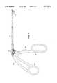
- FIG. 1is a overall view of the cutting instrument according to the invention.
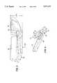
- FIG. 2is a detailed view of the cutting instrument with the jaw member in a fully open position
- FIG. 3is a detailed view of the cutting instrument with the jaw member in a fully closed position
- FIG. 4is an operational view of the cutting instrument as it cuts a meniscus member
- FIG. 5is a diagram showing the advantage of the smooth and thinned end section of the lower jaw member in accordance with a preferred embodiment of the invention.
- FIG. 6is a detailed bottom view of the cutting members in an open position.
- a medical surgical instrument 10has a cutting distal end assembly 12 attached through an elongated support shaft 14 to an actuating mechanism 16 controlled by a handle assembly 18.
- the instrument 10a so-called backbiter configuration, can be actuated by grasping end squeezing together the two finger grip members 20.
- the cutter mechanism at the distal endis in its open position. This is illustrated in more detail in FIG. 2.
- the cutting mechanismis illustrated in a fully closed position.
- the cutting assembly 12has a pivoting, ring-shaped lower movable jaw member 20 which cooperatively mates and aligns to a serrated fixed cutter member 22. Jaw member 20 and serrated member 22 cooperatively and cuttingly engaging in an aligned manner at opening 24 (see FIG. 3) in ring-shaped pivotable jaw member 20.
- the ring-shaped pivotable memberpivots about a pivot axis 26.
- the pivoting member 20is secured to the stationary elongated support shaft 14 at the pivot axis 26 by a pivot pin construction 30.
- the pivoting member 20is moved from a fully opened position as shown in FIG. 2 to a fully closed position as illustrated in FIG. 3 by a slidable pushrod member 32 which engages, in a half-moon arrangement, the pivoting member along a surface generally designated as 34.
- the pivoting ring-shaped lower jaw member 20pivots rearwardly in a direction indicated by arrow 40 toward and away from its closed position wherein the opening 24 mates with and tightly but not interferringly encloses the serrated land cutting member 22.
- the ring-shaped memberis tapered so that it has a thickness 43 at end 44 substantially less than the thickness 45 of the ring-shaped member at the opening 24. This reduced and smooth leading edge provides, as illustrated in FIG. 5, an advantageous ability to slide under and engage the meniscus for cutting or punching.
- the ring-shaped lower jaw memberis pivoted to its fully closed position by which the tissue is cut or punched and thus becomes freely moveable, for removal at the surgical site, typically by suction as the site is continuously flushed with liquid.
- the moveable ring-like jaw memberhas, referring to FIG. 4, sharp edges which form the cutting edges 50, 52, 54, 56 of opening 24, and which cooperate with corresponding cutting edges surfaces 60, 62, 64, 66 (FIG. 2) of the serrated fixed member 22.
- the action of closing ring-member 20acts to cut or punch any tissue caught within the space defined by opening 24 of ring-member 20.
- the serrations of fixed member 22, which extend parallel to each other and generally parallel to the pivot axis 26 about which the ring-like member rotates,tend to hold the tissue in place and to prevent it from slipping as the pivoting lower jaw member closes for cutting action.
- one of the serrations 74is higher than the rest, in the illustrated embodiment, and acts to prevent tissue from moving behind the serrated land member into the space 75 at which the pivoting member rotates, so that it thereby prevents blocking and jamming of the rotation of the closed member during normal operation.
- serration 74acts as a block to prevent tissue from moving into the distal end interior portion of the instrument support shaft.
- the medical instrument 10 with the lower ring like jaw member 20 in its fully opened positioncan be used to engage a meniscus tissue which has a shape substantially as identified at 80 in FIG. 4.
- the thin forward leading edge 44 of lower jaw member 20acts to more easily pick up and slide beneath the meniscus tissue, that is, between the meniscus and the tibial plateau, for example (FIG. 5).
- the instrumentis able to properly punch or cut the tissue, the punched or cut section being free to float at the surgical site and thereafter to be suctioned therefrom.
- the actuation mechanism for causing the member 20 to pivot around pivot axis 26is a pushrod arrangement having the pushrod 32, best identified in FIG. 3, which has at its distal end a moon or a semi-circular shaped actuating element 90.
- this elementmoves forward (toward the distal end), as best shown in FIGS. 2 and 3, it engages surface 34 of jaw member 20 and causes that surface to move forward thus rotating about pivot axis 26 and urging the lower jaw member to its closed position.
- the ring-shaped memberfully encompasses the serrated fixed cutting member in a manner so that the serrations do not extend beyond the underside of the closed assembly.
- the assemblythus achieves a low vertical profile, with small lateral extent, and can be more easily removed (or inserted) through a smaller portal, for example, an anterior medial or anterior lateral portal.
- the actuating member 32slides within the fixed shaft 14 of the medical instrument so that as it is withdrawn, that is pulled toward the end proximal to the handle, the half moon element of the slidable pushrod 32 acts against an extending surface 94 of the lower jaw member to cause the jaw member to pivot open as illustrated in FIGS. 2 and 3.
- both the sidewalls 62 and 66 of the fixed cutter member and 52 and 56 of the moveable lower jaw memberare both angled slightly from a normal to their respective bases, to better allow the pivoting member to fit accurately, snugly, and without mechanical interference, in an aligned cutting relationship as the pivoting jaw member closes over and around the fixed serrated land member.
- the shape of opening 24, and hence the corresponding mating shape of fixed portion 22can be altered as desired, and further the fixed portion 22 need not be serrated provided that its outer edges provide a cuttingly engaging interrelationship with corresponding edges of the ring-shaped member 20.
- the size of the cutting instrumentcan be varied, depending upon the joint (for example, knee or wrist) and suction can be added if desired.
Landscapes
- Health & Medical Sciences (AREA)
- Surgery (AREA)
- Life Sciences & Earth Sciences (AREA)
- Biomedical Technology (AREA)
- Medical Informatics (AREA)
- Orthopedic Medicine & Surgery (AREA)
- Oral & Maxillofacial Surgery (AREA)
- Engineering & Computer Science (AREA)
- Dentistry (AREA)
- Heart & Thoracic Surgery (AREA)
- Nuclear Medicine, Radiotherapy & Molecular Imaging (AREA)
- Molecular Biology (AREA)
- Animal Behavior & Ethology (AREA)
- General Health & Medical Sciences (AREA)
- Public Health (AREA)
- Veterinary Medicine (AREA)
- Surgical Instruments (AREA)
Abstract
Description
Claims (6)
Priority Applications (1)
| Application Number | Priority Date | Filing Date | Title |
|---|---|---|---|
| US08/484,984US5571131A (en) | 1995-06-07 | 1995-06-07 | Back biting punch |
Applications Claiming Priority (1)
| Application Number | Priority Date | Filing Date | Title |
|---|---|---|---|
| US08/484,984US5571131A (en) | 1995-06-07 | 1995-06-07 | Back biting punch |
Publications (1)
| Publication Number | Publication Date |
|---|---|
| US5571131Atrue US5571131A (en) | 1996-11-05 |
Family
ID=23926465
Family Applications (1)
| Application Number | Title | Priority Date | Filing Date |
|---|---|---|---|
| US08/484,984Expired - Fee RelatedUS5571131A (en) | 1995-06-07 | 1995-06-07 | Back biting punch |
Country Status (1)
| Country | Link |
|---|---|
| US (1) | US5571131A (en) |
Cited By (61)
| Publication number | Priority date | Publication date | Assignee | Title |
|---|---|---|---|---|
| US5755723A (en)* | 1997-04-18 | 1998-05-26 | Tnco, Inc. | Retrograde surgical instrument |
| WO1999011183A1 (en)* | 1997-09-03 | 1999-03-11 | Peter Doble | Back biting surgical instrument |
| US5913866A (en)* | 1997-06-19 | 1999-06-22 | Cardiothoracic Systems, Inc. | Devices and methods for harvesting vascular conduits |
| US5968062A (en)* | 1996-04-12 | 1999-10-19 | Surgical Dynamics, Inc. | Surgical cutting device removeably connected to a rotarty drive element |
| US5989277A (en)* | 1998-01-30 | 1999-11-23 | Lemaire, Iii; Norman J. | Surgical instrument with offset jaw actuator |
| US6575978B2 (en)* | 2001-04-05 | 2003-06-10 | Spineology, Inc. | Circumferential resecting reamer tool |
| US6679886B2 (en) | 2000-09-01 | 2004-01-20 | Synthes (Usa) | Tools and methods for creating cavities in bone |
| US20040122461A1 (en)* | 2002-12-18 | 2004-06-24 | Mcguire David A. | Surgical biting punch |
| US20060224160A1 (en)* | 2005-04-01 | 2006-10-05 | Trieu Hai H | Instruments and methods for aggressive yet continuous tissue removal |
| US20060276835A1 (en)* | 2005-04-26 | 2006-12-07 | Kazunori Uchida | Endoscopic surgical instrument |
| DE19906360B4 (en)* | 1999-02-16 | 2007-09-27 | Aesculap Ag & Co. Kg | Surgical tubular shaft instrument |
| US20080208249A1 (en)* | 2007-02-22 | 2008-08-28 | Jason Blain | Vertebral facet joint drill and method of use |
| US20090054898A1 (en)* | 2007-03-26 | 2009-02-26 | Joe Gleason | Articulating Shaper |
| US20110028898A1 (en)* | 2005-09-07 | 2011-02-03 | Cabochon Aesthetics, Inc. | Dissection handpiece and method for reducing the appearance of cellulite |
| US20110295297A1 (en)* | 2010-05-26 | 2011-12-01 | Medicinelodge, Inc. Dba Imds Co-Innovation | Dice cutting surgical instrument |
| US8439940B2 (en) | 2010-12-22 | 2013-05-14 | Cabochon Aesthetics, Inc. | Dissection handpiece with aspiration means for reducing the appearance of cellulite |
| US8518069B2 (en) | 2005-09-07 | 2013-08-27 | Cabochon Aesthetics, Inc. | Dissection handpiece and method for reducing the appearance of cellulite |
| USD691266S1 (en)* | 2011-12-29 | 2013-10-08 | Karl Storz Gmbh & Co. Kg | Medical punch |
| US20130325048A1 (en)* | 2012-05-31 | 2013-12-05 | Mark Weiman | Laparoscopic Manipulation |
| US8740949B2 (en) | 2011-02-24 | 2014-06-03 | Spinal Elements, Inc. | Methods and apparatus for stabilizing bone |
| US8858597B2 (en) | 2004-02-06 | 2014-10-14 | Spinal Elements, Inc. | Vertebral facet joint prosthesis and method of fixation |
| USD724733S1 (en) | 2011-02-24 | 2015-03-17 | Spinal Elements, Inc. | Interbody bone implant |
| US8992533B2 (en) | 2007-02-22 | 2015-03-31 | Spinal Elements, Inc. | Vertebral facet joint drill and method of use |
| US9011473B2 (en) | 2005-09-07 | 2015-04-21 | Ulthera, Inc. | Dissection handpiece and method for reducing the appearance of cellulite |
| US9248317B2 (en) | 2005-12-02 | 2016-02-02 | Ulthera, Inc. | Devices and methods for selectively lysing cells |
| US9272124B2 (en) | 2005-12-02 | 2016-03-01 | Ulthera, Inc. | Systems and devices for selective cell lysis and methods of using same |
| US9271765B2 (en) | 2011-02-24 | 2016-03-01 | Spinal Elements, Inc. | Vertebral facet joint fusion implant and method for fusion |
| US9358033B2 (en) | 2005-09-07 | 2016-06-07 | Ulthera, Inc. | Fluid-jet dissection system and method for reducing the appearance of cellulite |
| US9358064B2 (en) | 2009-08-07 | 2016-06-07 | Ulthera, Inc. | Handpiece and methods for performing subcutaneous surgery |
| US9421044B2 (en) | 2013-03-14 | 2016-08-23 | Spinal Elements, Inc. | Apparatus for bone stabilization and distraction and methods of use |
| USD765854S1 (en) | 2011-10-26 | 2016-09-06 | Spinal Elements, Inc. | Interbody bone implant |
| USD765853S1 (en) | 2013-03-14 | 2016-09-06 | Spinal Elements, Inc. | Flexible elongate member with a portion configured to receive a bone anchor |
| US20160262744A1 (en)* | 2013-11-04 | 2016-09-15 | Quickring Medical Technologies Ltd. | Surgical stapler |
| US9456855B2 (en) | 2013-09-27 | 2016-10-04 | Spinal Elements, Inc. | Method of placing an implant between bone portions |
| US9820784B2 (en) | 2013-03-14 | 2017-11-21 | Spinal Elements, Inc. | Apparatus for spinal fixation and methods of use |
| US9839450B2 (en) | 2013-09-27 | 2017-12-12 | Spinal Elements, Inc. | Device and method for reinforcement of a facet |
| US9931142B2 (en) | 2004-06-10 | 2018-04-03 | Spinal Elements, Inc. | Implant and method for facet immobilization |
| US20180199941A1 (en)* | 2014-03-29 | 2018-07-19 | Standard Bariatrics, Inc. | Compression mechanism for surgical stapling devices |
| US10278707B2 (en) | 2013-12-17 | 2019-05-07 | Standard Bariatrics, Inc. | Resection line guide for a medical procedure and method of using same |
| US10285837B1 (en) | 2015-09-16 | 2019-05-14 | Standard Bariatrics, Inc. | Systems and methods for measuring volume of potential sleeve in a sleeve gastrectomy |
| US10405860B2 (en) | 2014-03-29 | 2019-09-10 | Standard Bariatrics, Inc. | End effectors, surgical stapling devices, and methods of using same |
| US10470911B2 (en) | 2014-09-05 | 2019-11-12 | Standard Bariatrics, Inc. | Sleeve gastrectomy calibration tube and method of using same |
| CN110505849A (en)* | 2017-02-01 | 2019-11-26 | 脊柱稳定技术公司 | Surgical cutting instrument |
| US10548659B2 (en) | 2006-01-17 | 2020-02-04 | Ulthera, Inc. | High pressure pre-burst for improved fluid delivery |
| US10548597B2 (en) | 2017-08-14 | 2020-02-04 | Standard Bariatrics, Inc. | Surgical stapling devices and methods of using same |
| US10758361B2 (en) | 2015-01-27 | 2020-09-01 | Spinal Elements, Inc. | Facet joint implant |
| US20210085359A1 (en)* | 2019-09-20 | 2021-03-25 | Spineology Inc. | Articulating curette |
| CN112971881A (en)* | 2021-02-02 | 2021-06-18 | 杭州锐健马斯汀医疗器材有限公司 | Joint mirror lower meniscus anterior angle sewing gun |
| US11096708B2 (en) | 2009-08-07 | 2021-08-24 | Ulthera, Inc. | Devices and methods for performing subcutaneous surgery |
| US11173060B2 (en) | 2019-11-04 | 2021-11-16 | Standard Bariatrics, Inc. | Systems and methods of performing surgery using Laplace's law tension retraction during surgery |
| US11304733B2 (en) | 2020-02-14 | 2022-04-19 | Spinal Elements, Inc. | Bone tie methods |
| US11452574B1 (en) | 2021-03-23 | 2022-09-27 | Standard Bariatrics, Inc. | Systems and methods for preventing tissue migration in surgical staplers |
| US11457959B2 (en) | 2019-05-22 | 2022-10-04 | Spinal Elements, Inc. | Bone tie and bone tie inserter |
| US11464552B2 (en) | 2019-05-22 | 2022-10-11 | Spinal Elements, Inc. | Bone tie and bone tie inserter |
| US11478275B2 (en) | 2014-09-17 | 2022-10-25 | Spinal Elements, Inc. | Flexible fastening band connector |
| CN115317067A (en)* | 2022-07-25 | 2022-11-11 | 浙江大学 | A new type of bite forceps for knee arthroscopy |
| US11871940B2 (en) | 2018-11-27 | 2024-01-16 | Sunnybrook Research Institute | Cartilage slicing apparatus and methods therefor |
| US12064142B2 (en) | 2020-06-30 | 2024-08-20 | Standard Bariatrics, Inc. | Systems, devices, and methods for preventing or reducing loss of insufflation during a laparoscopic surgical procedure |
| RU230096U1 (en)* | 2024-09-02 | 2024-11-14 | Артур Факилевич Аглиуллин | Forceps for opening and widening the sphenoid sinus ostium with the function of removing pathological tissues |
| US12274635B2 (en) | 2019-11-04 | 2025-04-15 | Standard Bariatrics, Inc. | Systems and methods of performing surgery using laplace's law tension retraction during surgery |
| US12369952B2 (en) | 2021-12-10 | 2025-07-29 | Spinal Elements, Inc. | Bone tie and portal |
Citations (7)
| Publication number | Priority date | Publication date | Assignee | Title |
|---|---|---|---|---|
| US5112346A (en)* | 1989-06-08 | 1992-05-12 | Richard Wolf Gmbh | Retrograde cutting hook punch |
| WO1992008415A1 (en)* | 1990-11-09 | 1992-05-29 | Arthrotek, Inc. | Surgical cutting instrument |
| US5219357A (en)* | 1990-05-31 | 1993-06-15 | Tnco, Inc. | Micro-instrument |
| US5286255A (en)* | 1991-07-29 | 1994-02-15 | Linvatec Corporation | Surgical forceps |
| US5327896A (en)* | 1993-06-30 | 1994-07-12 | Arthrex, Inc. | Suction downbiter |
| US5352235A (en)* | 1992-03-16 | 1994-10-04 | Tibor Koros | Laparoscopic grasper and cutter |
| US5389104A (en)* | 1992-11-18 | 1995-02-14 | Symbiosis Corporation | Arthroscopic surgical instruments |
- 1995
- 1995-06-07USUS08/484,984patent/US5571131A/ennot_activeExpired - Fee Related
Patent Citations (8)
| Publication number | Priority date | Publication date | Assignee | Title |
|---|---|---|---|---|
| US5112346A (en)* | 1989-06-08 | 1992-05-12 | Richard Wolf Gmbh | Retrograde cutting hook punch |
| US5219357A (en)* | 1990-05-31 | 1993-06-15 | Tnco, Inc. | Micro-instrument |
| WO1992008415A1 (en)* | 1990-11-09 | 1992-05-29 | Arthrotek, Inc. | Surgical cutting instrument |
| US5443475A (en)* | 1990-11-09 | 1995-08-22 | Arthrotek, Inc. | Surgical instrument |
| US5286255A (en)* | 1991-07-29 | 1994-02-15 | Linvatec Corporation | Surgical forceps |
| US5352235A (en)* | 1992-03-16 | 1994-10-04 | Tibor Koros | Laparoscopic grasper and cutter |
| US5389104A (en)* | 1992-11-18 | 1995-02-14 | Symbiosis Corporation | Arthroscopic surgical instruments |
| US5327896A (en)* | 1993-06-30 | 1994-07-12 | Arthrex, Inc. | Suction downbiter |
Non-Patent Citations (6)
| Title |
|---|
| Brochure, Acufex , Stingray The Anterior Horn Punch From Acufex. , 1994.* |
| Brochure, Acufex Product Catalog, The quality you expect. The Refinements you demand, 1994.* |
| Brochure, Acufex® Product Catalog, "The quality you expect. The Refinements you demand," 1994. |
| Brochure, Acufex®, "Stingray The Anterior Horn Punch From Acufex.", 1994. |
| Brochure, Linvatec, "Introducing the Shut® Mantis™ Retrograde Forceps" 1993 Linvatech Corp. |
| Brochure, Linvatec, Introducing the Shut Mantis Retrograde Forceps 1993 Linvatech Corp.* |
Cited By (154)
| Publication number | Priority date | Publication date | Assignee | Title |
|---|---|---|---|---|
| US5968062A (en)* | 1996-04-12 | 1999-10-19 | Surgical Dynamics, Inc. | Surgical cutting device removeably connected to a rotarty drive element |
| US5755723A (en)* | 1997-04-18 | 1998-05-26 | Tnco, Inc. | Retrograde surgical instrument |
| US5913866A (en)* | 1997-06-19 | 1999-06-22 | Cardiothoracic Systems, Inc. | Devices and methods for harvesting vascular conduits |
| WO1999011183A1 (en)* | 1997-09-03 | 1999-03-11 | Peter Doble | Back biting surgical instrument |
| US6364891B1 (en)* | 1997-09-03 | 2002-04-02 | Peter Doble | Back biting surgical instrument |
| US5989277A (en)* | 1998-01-30 | 1999-11-23 | Lemaire, Iii; Norman J. | Surgical instrument with offset jaw actuator |
| DE19906360B4 (en)* | 1999-02-16 | 2007-09-27 | Aesculap Ag & Co. Kg | Surgical tubular shaft instrument |
| US6679886B2 (en) | 2000-09-01 | 2004-01-20 | Synthes (Usa) | Tools and methods for creating cavities in bone |
| US7476226B2 (en) | 2000-09-01 | 2009-01-13 | Synthes (U.S.A.) | Tools and methods for creating cavities in bone |
| US6575978B2 (en)* | 2001-04-05 | 2003-06-10 | Spineology, Inc. | Circumferential resecting reamer tool |
| US7559940B2 (en)* | 2002-12-18 | 2009-07-14 | Smith & Nephew, Inc. | Surgical biting punch |
| AU2003299698B2 (en)* | 2002-12-18 | 2009-07-16 | Smith & Nephew, Inc. | Surgical biting punch |
| JP4842540B2 (en)* | 2002-12-18 | 2011-12-21 | スミス アンド ネフュー インコーポレーテッド | Surgical bite punch |
| US20040122461A1 (en)* | 2002-12-18 | 2004-06-24 | Mcguire David A. | Surgical biting punch |
| JP2006511273A (en)* | 2002-12-18 | 2006-04-06 | スミス アンド ネフュー インコーポレーテッド | Surgical bite punch |
| US10085776B2 (en) | 2004-02-06 | 2018-10-02 | Spinal Elements, Inc. | Vertebral facet joint prosthesis and method of fixation |
| US8858597B2 (en) | 2004-02-06 | 2014-10-14 | Spinal Elements, Inc. | Vertebral facet joint prosthesis and method of fixation |
| US9675387B2 (en) | 2004-02-06 | 2017-06-13 | Spinal Elements, Inc. | Vertebral facet joint prosthesis and method of fixation |
| US8882804B2 (en) | 2004-02-06 | 2014-11-11 | Spinal Elements, Inc. | Vertebral facet joint prosthesis and method of fixation |
| US8998953B2 (en) | 2004-02-06 | 2015-04-07 | Spinal Elements, Inc. | Vertebral facet joint prosthesis and method of fixation |
| US9931142B2 (en) | 2004-06-10 | 2018-04-03 | Spinal Elements, Inc. | Implant and method for facet immobilization |
| US20060224160A1 (en)* | 2005-04-01 | 2006-10-05 | Trieu Hai H | Instruments and methods for aggressive yet continuous tissue removal |
| US20060276835A1 (en)* | 2005-04-26 | 2006-12-07 | Kazunori Uchida | Endoscopic surgical instrument |
| US8518069B2 (en) | 2005-09-07 | 2013-08-27 | Cabochon Aesthetics, Inc. | Dissection handpiece and method for reducing the appearance of cellulite |
| US9364246B2 (en) | 2005-09-07 | 2016-06-14 | Ulthera, Inc. | Dissection handpiece and method for reducing the appearance of cellulite |
| US9358033B2 (en) | 2005-09-07 | 2016-06-07 | Ulthera, Inc. | Fluid-jet dissection system and method for reducing the appearance of cellulite |
| US9486274B2 (en) | 2005-09-07 | 2016-11-08 | Ulthera, Inc. | Dissection handpiece and method for reducing the appearance of cellulite |
| US9179928B2 (en) | 2005-09-07 | 2015-11-10 | Ulthera, Inc. | Dissection handpiece and method for reducing the appearance of cellulite |
| US20110028898A1 (en)* | 2005-09-07 | 2011-02-03 | Cabochon Aesthetics, Inc. | Dissection handpiece and method for reducing the appearance of cellulite |
| US9011473B2 (en) | 2005-09-07 | 2015-04-21 | Ulthera, Inc. | Dissection handpiece and method for reducing the appearance of cellulite |
| US9005229B2 (en) | 2005-09-07 | 2015-04-14 | Ulthera, Inc. | Dissection handpiece and method for reducing the appearance of cellulite |
| US9272124B2 (en) | 2005-12-02 | 2016-03-01 | Ulthera, Inc. | Systems and devices for selective cell lysis and methods of using same |
| US9248317B2 (en) | 2005-12-02 | 2016-02-02 | Ulthera, Inc. | Devices and methods for selectively lysing cells |
| US10548659B2 (en) | 2006-01-17 | 2020-02-04 | Ulthera, Inc. | High pressure pre-burst for improved fluid delivery |
| US8652137B2 (en)* | 2007-02-22 | 2014-02-18 | Spinal Elements, Inc. | Vertebral facet joint drill and method of use |
| US9517077B2 (en) | 2007-02-22 | 2016-12-13 | Spinal Elements, Inc. | Vertebral facet joint drill and method of use |
| US8992533B2 (en) | 2007-02-22 | 2015-03-31 | Spinal Elements, Inc. | Vertebral facet joint drill and method of use |
| US20080208249A1 (en)* | 2007-02-22 | 2008-08-28 | Jason Blain | Vertebral facet joint drill and method of use |
| US9743937B2 (en) | 2007-02-22 | 2017-08-29 | Spinal Elements, Inc. | Vertebral facet joint drill and method of use |
| US9060787B2 (en) | 2007-02-22 | 2015-06-23 | Spinal Elements, Inc. | Method of using a vertebral facet joint drill |
| US20090054898A1 (en)* | 2007-03-26 | 2009-02-26 | Joe Gleason | Articulating Shaper |
| US9039722B2 (en) | 2007-10-09 | 2015-05-26 | Ulthera, Inc. | Dissection handpiece with aspiration means for reducing the appearance of cellulite |
| US10220122B2 (en) | 2007-10-09 | 2019-03-05 | Ulthera, Inc. | System for tissue dissection and aspiration |
| US11096708B2 (en) | 2009-08-07 | 2021-08-24 | Ulthera, Inc. | Devices and methods for performing subcutaneous surgery |
| US8900262B2 (en) | 2009-08-07 | 2014-12-02 | Ulthera, Inc. | Device for dissection of subcutaneous tissue |
| US8894678B2 (en) | 2009-08-07 | 2014-11-25 | Ulthera, Inc. | Cellulite treatment methods |
| US10531888B2 (en) | 2009-08-07 | 2020-01-14 | Ulthera, Inc. | Methods for efficiently reducing the appearance of cellulite |
| US10485573B2 (en) | 2009-08-07 | 2019-11-26 | Ulthera, Inc. | Handpieces for tissue treatment |
| US8979881B2 (en) | 2009-08-07 | 2015-03-17 | Ulthera, Inc. | Methods and handpiece for use in tissue dissection |
| US9078688B2 (en) | 2009-08-07 | 2015-07-14 | Ulthera, Inc. | Handpiece for use in tissue dissection |
| US10271866B2 (en) | 2009-08-07 | 2019-04-30 | Ulthera, Inc. | Modular systems for treating tissue |
| US9044259B2 (en) | 2009-08-07 | 2015-06-02 | Ulthera, Inc. | Methods for dissection of subcutaneous tissue |
| US8906054B2 (en) | 2009-08-07 | 2014-12-09 | Ulthera, Inc. | Apparatus for reducing the appearance of cellulite |
| US9358064B2 (en) | 2009-08-07 | 2016-06-07 | Ulthera, Inc. | Handpiece and methods for performing subcutaneous surgery |
| US11337725B2 (en) | 2009-08-07 | 2022-05-24 | Ulthera, Inc. | Handpieces for tissue treatment |
| US9510849B2 (en) | 2009-08-07 | 2016-12-06 | Ulthera, Inc. | Devices and methods for performing subcutaneous surgery |
| US8920452B2 (en) | 2009-08-07 | 2014-12-30 | Ulthera, Inc. | Methods of tissue release to reduce the appearance of cellulite |
| US8900261B2 (en) | 2009-08-07 | 2014-12-02 | Ulthera, Inc. | Tissue treatment system for reducing the appearance of cellulite |
| US9757145B2 (en) | 2009-08-07 | 2017-09-12 | Ulthera, Inc. | Dissection handpiece and method for reducing the appearance of cellulite |
| US10603066B2 (en) | 2010-05-25 | 2020-03-31 | Ulthera, Inc. | Fluid-jet dissection system and method for reducing the appearance of cellulite |
| US20110295297A1 (en)* | 2010-05-26 | 2011-12-01 | Medicinelodge, Inc. Dba Imds Co-Innovation | Dice cutting surgical instrument |
| US8439940B2 (en) | 2010-12-22 | 2013-05-14 | Cabochon Aesthetics, Inc. | Dissection handpiece with aspiration means for reducing the appearance of cellulite |
| US11213618B2 (en) | 2010-12-22 | 2022-01-04 | Ulthera, Inc. | System for tissue dissection and aspiration |
| US10022161B2 (en) | 2011-02-24 | 2018-07-17 | Spinal Elements, Inc. | Vertebral facet joint fusion implant and method for fusion |
| US11464551B2 (en) | 2011-02-24 | 2022-10-11 | Spinal Elements, Inc. | Methods and apparatus for stabilizing bone |
| US8740949B2 (en) | 2011-02-24 | 2014-06-03 | Spinal Elements, Inc. | Methods and apparatus for stabilizing bone |
| USD777921S1 (en) | 2011-02-24 | 2017-01-31 | Spinal Elements, Inc. | Interbody bone implant |
| USD724733S1 (en) | 2011-02-24 | 2015-03-17 | Spinal Elements, Inc. | Interbody bone implant |
| US9179943B2 (en) | 2011-02-24 | 2015-11-10 | Spinal Elements, Inc. | Methods and apparatus for stabilizing bone |
| USD748262S1 (en) | 2011-02-24 | 2016-01-26 | Spinal Elements, Inc. | Interbody bone implant |
| US9808294B2 (en) | 2011-02-24 | 2017-11-07 | Spinal Elements, Inc. | Methods and apparatus for stabilizing bone |
| USD748793S1 (en) | 2011-02-24 | 2016-02-02 | Spinal Elements, Inc. | Interbody bone implant |
| US9572602B2 (en) | 2011-02-24 | 2017-02-21 | Spinal Elements, Inc. | Vertebral facet joint fusion implant and method for fusion |
| US10368921B2 (en) | 2011-02-24 | 2019-08-06 | Spinal Elements, Inc. | Methods and apparatus for stabilizing bone |
| US9271765B2 (en) | 2011-02-24 | 2016-03-01 | Spinal Elements, Inc. | Vertebral facet joint fusion implant and method for fusion |
| US9301786B2 (en) | 2011-02-24 | 2016-04-05 | Spinal Elements, Inc. | Methods and apparatus for stabilizing bone |
| US12343048B2 (en) | 2011-02-24 | 2025-07-01 | Spinal Elements, Inc. | Methods and apparatus for stabilizing bone |
| USD979062S1 (en) | 2011-10-26 | 2023-02-21 | Spinal Elements, Inc. | Interbody bone implant |
| USD926982S1 (en) | 2011-10-26 | 2021-08-03 | Spinal Elements, Inc. | Interbody bone implant |
| USD834194S1 (en) | 2011-10-26 | 2018-11-20 | Spinal Elements, Inc. | Interbody bone implant |
| USD884896S1 (en) | 2011-10-26 | 2020-05-19 | Spinal Elements, Inc. | Interbody bone implant |
| USD790062S1 (en) | 2011-10-26 | 2017-06-20 | Spinal Elements, Inc. | Interbody bone implant |
| USD765854S1 (en) | 2011-10-26 | 2016-09-06 | Spinal Elements, Inc. | Interbody bone implant |
| USD958366S1 (en) | 2011-10-26 | 2022-07-19 | Spinal Elements, Inc. | Interbody bone implant |
| USD857900S1 (en) | 2011-10-26 | 2019-08-27 | Spinal Elements, Inc. | Interbody bone implant |
| USD810942S1 (en) | 2011-10-26 | 2018-02-20 | Spinal Elements, Inc. | Interbody bone implant |
| USD691266S1 (en)* | 2011-12-29 | 2013-10-08 | Karl Storz Gmbh & Co. Kg | Medical punch |
| US20130325048A1 (en)* | 2012-05-31 | 2013-12-05 | Mark Weiman | Laparoscopic Manipulation |
| USD812754S1 (en) | 2013-03-14 | 2018-03-13 | Spinal Elements, Inc. | Flexible elongate member with a portion configured to receive a bone anchor |
| US9820784B2 (en) | 2013-03-14 | 2017-11-21 | Spinal Elements, Inc. | Apparatus for spinal fixation and methods of use |
| US9421044B2 (en) | 2013-03-14 | 2016-08-23 | Spinal Elements, Inc. | Apparatus for bone stabilization and distraction and methods of use |
| USD780315S1 (en) | 2013-03-14 | 2017-02-28 | Spinal Elements, Inc. | Flexible elongate member with a portion configured to receive a bone anchor |
| US10426524B2 (en) | 2013-03-14 | 2019-10-01 | Spinal Elements, Inc. | Apparatus for spinal fixation and methods of use |
| USD765853S1 (en) | 2013-03-14 | 2016-09-06 | Spinal Elements, Inc. | Flexible elongate member with a portion configured to receive a bone anchor |
| US11272961B2 (en) | 2013-03-14 | 2022-03-15 | Spinal Elements, Inc. | Apparatus for bone stabilization and distraction and methods of use |
| US10251679B2 (en) | 2013-03-14 | 2019-04-09 | Spinal Elements, Inc. | Apparatus for bone stabilization and distraction and methods of use |
| US11918258B2 (en) | 2013-09-27 | 2024-03-05 | Spinal Elements, Inc. | Device and method for reinforcement of a facet |
| US9456855B2 (en) | 2013-09-27 | 2016-10-04 | Spinal Elements, Inc. | Method of placing an implant between bone portions |
| US10624680B2 (en) | 2013-09-27 | 2020-04-21 | Spinal Elements, Inc. | Device and method for reinforcement of a facet |
| US9839450B2 (en) | 2013-09-27 | 2017-12-12 | Spinal Elements, Inc. | Device and method for reinforcement of a facet |
| US10194955B2 (en) | 2013-09-27 | 2019-02-05 | Spinal Elements, Inc. | Method of placing an implant between bone portions |
| US11517354B2 (en) | 2013-09-27 | 2022-12-06 | Spinal Elements, Inc. | Method of placing an implant between bone portions |
| US20160262744A1 (en)* | 2013-11-04 | 2016-09-15 | Quickring Medical Technologies Ltd. | Surgical stapler |
| US10278695B2 (en)* | 2013-11-04 | 2019-05-07 | Quickring Medical Technologies Ltd. | Surgical stapler |
| US11911044B2 (en) | 2013-12-17 | 2024-02-27 | Standard Bariatrics, Inc. | Resection line guide for a medical procedure and method of using same |
| US10987108B2 (en) | 2013-12-17 | 2021-04-27 | Standard Bariatrics, Inc. | Resection line guide for a medical procedure and method of using same |
| US10278707B2 (en) | 2013-12-17 | 2019-05-07 | Standard Bariatrics, Inc. | Resection line guide for a medical procedure and method of using same |
| US11510672B2 (en) | 2014-03-29 | 2022-11-29 | Standard Bariatrics, Inc. | End effectors, surgical stapling devices, and methods of using same |
| US10278699B2 (en) | 2014-03-29 | 2019-05-07 | Standard Bariatrics, Inc. | End effectors, surgical stapling devices, and methods of using same |
| US20180199941A1 (en)* | 2014-03-29 | 2018-07-19 | Standard Bariatrics, Inc. | Compression mechanism for surgical stapling devices |
| US12053178B2 (en) | 2014-03-29 | 2024-08-06 | Standard Bariatrics, Inc. | End effectors, surgical stapling devices, and methods of using same |
| US10231734B2 (en)* | 2014-03-29 | 2019-03-19 | Standard Bariatrics, Inc. | Compression mechanism for surgical stapling devices |
| US11812962B2 (en) | 2014-03-29 | 2023-11-14 | Standard Bariatrics, Inc. | End effectors, surgical stapling devices, and methods of using same |
| US11717295B2 (en) | 2014-03-29 | 2023-08-08 | Standard Bariatrics, Inc. | End effectors, surgical stapling devices, and methods of using same |
| US11096686B2 (en) | 2014-03-29 | 2021-08-24 | Standard Bariatrics, Inc. | End effectors, surgical stapling devices, and methods of using same |
| US11633184B2 (en) | 2014-03-29 | 2023-04-25 | Standard Bariatrics, Inc. | End effectors, surgical stapling devices, and methods of using same |
| US10405860B2 (en) | 2014-03-29 | 2019-09-10 | Standard Bariatrics, Inc. | End effectors, surgical stapling devices, and methods of using same |
| US10441283B1 (en) | 2014-03-29 | 2019-10-15 | Standard Bariatrics, Inc. | End effectors, surgical stapling devices, and methods of using same |
| US10624638B2 (en) | 2014-03-29 | 2020-04-21 | Standard Bariatrics, Inc. | End effectors, surgical stapling devices, and methods of using same |
| US10542986B2 (en) | 2014-03-29 | 2020-01-28 | Standard Bariatrics, Inc. | End effectors, surgical stapling devices, and methods of using same |
| US10470911B2 (en) | 2014-09-05 | 2019-11-12 | Standard Bariatrics, Inc. | Sleeve gastrectomy calibration tube and method of using same |
| US11998240B2 (en) | 2014-09-17 | 2024-06-04 | Spinal Elements, Inc. | Flexible fastening band connector |
| US11478275B2 (en) | 2014-09-17 | 2022-10-25 | Spinal Elements, Inc. | Flexible fastening band connector |
| US10758361B2 (en) | 2015-01-27 | 2020-09-01 | Spinal Elements, Inc. | Facet joint implant |
| US12329668B2 (en) | 2015-09-16 | 2025-06-17 | Standard Bariatrics, Inc. | Systems and methods for measuring volume of potential sleeve in a sleeve gastrectomy |
| US11324620B2 (en) | 2015-09-16 | 2022-05-10 | Standard Bariatrics, Inc. | Systems and methods for measuring volume of potential sleeve in a sleeve gastrectomy |
| US10285837B1 (en) | 2015-09-16 | 2019-05-14 | Standard Bariatrics, Inc. | Systems and methods for measuring volume of potential sleeve in a sleeve gastrectomy |
| CN110505849A (en)* | 2017-02-01 | 2019-11-26 | 脊柱稳定技术公司 | Surgical cutting instrument |
| US10548597B2 (en) | 2017-08-14 | 2020-02-04 | Standard Bariatrics, Inc. | Surgical stapling devices and methods of using same |
| US11197672B2 (en) | 2017-08-14 | 2021-12-14 | Standard Bariatrics, Inc. | Buttress systems and methods for surgical stapling devices and end effectors |
| US11559305B2 (en) | 2017-08-14 | 2023-01-24 | Standard Bariatrics, Inc. | Stapling systems and methods for surgical devices and end effectors |
| US10966721B2 (en) | 2017-08-14 | 2021-04-06 | Standard Bariatrics, Inc. | End effectors, surgical stapling devices, and methods of using same |
| US10687814B2 (en) | 2017-08-14 | 2020-06-23 | Standard Bariatrics, Inc. | Stapling systems and methods for surgical devices and end effectors |
| US10849623B2 (en) | 2017-08-14 | 2020-12-01 | Standard Bariatrics, Inc. | Buttress systems and methods for surgical stapling devices and end effectors |
| US11871927B2 (en) | 2017-08-14 | 2024-01-16 | Standard Bariatrics, Inc. | End effectors, surgical stapling devices, and methods of using same |
| US10912562B2 (en) | 2017-08-14 | 2021-02-09 | Standard Bariatrics, Inc. | End effectors, surgical stapling devices, and methods of using same |
| US11911033B2 (en) | 2017-08-14 | 2024-02-27 | Standard Bariatrics, Inc. | Stapling systems and methods for surgical devices and end effectors |
| US11871940B2 (en) | 2018-11-27 | 2024-01-16 | Sunnybrook Research Institute | Cartilage slicing apparatus and methods therefor |
| US11464552B2 (en) | 2019-05-22 | 2022-10-11 | Spinal Elements, Inc. | Bone tie and bone tie inserter |
| US11457959B2 (en) | 2019-05-22 | 2022-10-04 | Spinal Elements, Inc. | Bone tie and bone tie inserter |
| US20210085359A1 (en)* | 2019-09-20 | 2021-03-25 | Spineology Inc. | Articulating curette |
| US11173060B2 (en) | 2019-11-04 | 2021-11-16 | Standard Bariatrics, Inc. | Systems and methods of performing surgery using Laplace's law tension retraction during surgery |
| US11602449B2 (en) | 2019-11-04 | 2023-03-14 | Standard Bariatrics, Inc. | Systems and methods of performing surgery using Laplace's law tension retraction during surgery |
| US12274635B2 (en) | 2019-11-04 | 2025-04-15 | Standard Bariatrics, Inc. | Systems and methods of performing surgery using laplace's law tension retraction during surgery |
| US11304733B2 (en) | 2020-02-14 | 2022-04-19 | Spinal Elements, Inc. | Bone tie methods |
| US12232778B2 (en) | 2020-02-14 | 2025-02-25 | Spinal Elements, Inc. | Bone tie methods |
| US12064142B2 (en) | 2020-06-30 | 2024-08-20 | Standard Bariatrics, Inc. | Systems, devices, and methods for preventing or reducing loss of insufflation during a laparoscopic surgical procedure |
| CN112971881A (en)* | 2021-02-02 | 2021-06-18 | 杭州锐健马斯汀医疗器材有限公司 | Joint mirror lower meniscus anterior angle sewing gun |
| US11452574B1 (en) | 2021-03-23 | 2022-09-27 | Standard Bariatrics, Inc. | Systems and methods for preventing tissue migration in surgical staplers |
| US12295793B2 (en) | 2021-03-23 | 2025-05-13 | Standard Bariatrics, Inc. | Systems and methods for preventing tissue migration in surgical staplers |
| US12369952B2 (en) | 2021-12-10 | 2025-07-29 | Spinal Elements, Inc. | Bone tie and portal |
| CN115317067A (en)* | 2022-07-25 | 2022-11-11 | 浙江大学 | A new type of bite forceps for knee arthroscopy |
| US12440242B2 (en) | 2024-04-29 | 2025-10-14 | Spinal Elements, Inc. | Flexible fastening band connector |
| RU230096U1 (en)* | 2024-09-02 | 2024-11-14 | Артур Факилевич Аглиуллин | Forceps for opening and widening the sphenoid sinus ostium with the function of removing pathological tissues |
Similar Documents
| Publication | Publication Date | Title |
|---|---|---|
| US5571131A (en) | Back biting punch | |
| EP1572013B1 (en) | Surgical biting punch | |
| US5129913A (en) | Surgical punch apparatus | |
| US6033419A (en) | Apparatus and method for cutting a heart valve annulus | |
| US5327896A (en) | Suction downbiter | |
| US5196023A (en) | Surgical needle holder and cutter for an endo-suture, endo-ligature or the like | |
| US7105005B2 (en) | Arteriotomy scissors for minimally invasive surgical procedures | |
| US5709697A (en) | Apparatus and method for removing tissue | |
| US4433687A (en) | Microsurgical scissors | |
| KR101399298B1 (en) | Morcellator with detachable handle | |
| US4766897A (en) | Capsulectomy surgical instrument | |
| US5643307A (en) | Colposcopic biopsy punch with removable multiple sample basket | |
| WO1992008415A1 (en) | Surgical cutting instrument | |
| US3915169A (en) | Surgical knife having malleable shank | |
| US6283924B1 (en) | Endoscopic biopsy forceps | |
| EP0904738A3 (en) | Electrosurgical cutting instrument | |
| CA2802716C (en) | Disposable suture cutter | |
| JP3810157B2 (en) | Suction biopsy tool | |
| US6328749B1 (en) | Remote endarterectomy ring stripper | |
| WO1996003926A1 (en) | Arthroscopic surgical punch | |
| US5487745A (en) | Curvilinear surgical punch | |
| US10413290B1 (en) | Combined needle holder scissors | |
| JPH02503999A (en) | tendon stripping device | |
| CN117770910A (en) | Intelligent force feedback orthopedic operation tool | |
| JPH11299799A (en) | Forceps |
Legal Events
| Date | Code | Title | Description |
|---|---|---|---|
| AS | Assignment | Owner name:SMITH & NEPHEW DYONICS, INC., MASSACHUSETTS Free format text:ASSIGNMENT OF ASSIGNORS INTEREST;ASSIGNORS:EK, STEVEN;AUERBACH, DAVID M.;REEL/FRAME:007606/0027;SIGNING DATES FROM 19950807 TO 19950824 | |
| AS | Assignment | Owner name:SMITH & NEPHEW, INC., TENNESSEE Free format text:MERGER;ASSIGNOR:SMITH & NEPHEW ENDOSCOPY, INC.;REEL/FRAME:008478/0517 Effective date:19961126 | |
| AS | Assignment | Owner name:SMITH & NEPHEW ENDOSCOPY, INC., MASSACHUSETTS Free format text:CHANGE OF NAME;ASSIGNOR:SMITH & NEPHEW DYONICS, INC.;REEL/FRAME:008693/0407 Effective date:19951010 | |
| FEPP | Fee payment procedure | Free format text:PAT HOLDER CLAIMS SMALL ENTITY STATUS - SMALL BUSINESS (ORIGINAL EVENT CODE: SM02); ENTITY STATUS OF PATENT OWNER: SMALL ENTITY | |
| FPAY | Fee payment | Year of fee payment:4 | |
| REMI | Maintenance fee reminder mailed | ||
| REMI | Maintenance fee reminder mailed | ||
| LAPS | Lapse for failure to pay maintenance fees | ||
| STCH | Information on status: patent discontinuation | Free format text:PATENT EXPIRED DUE TO NONPAYMENT OF MAINTENANCE FEES UNDER 37 CFR 1.362 | |
| FP | Lapsed due to failure to pay maintenance fee | Effective date:20041105 |