US5570300A - Self-validating sensors - Google Patents
Self-validating sensorsDownload PDFInfo
- Publication number
- US5570300A US5570300AUS08/406,805US40680595AUS5570300AUS 5570300 AUS5570300 AUS 5570300AUS 40680595 AUS40680595 AUS 40680595AUS 5570300 AUS5570300 AUS 5570300A
- Authority
- US
- United States
- Prior art keywords
- measurement
- uncertainty
- estimate
- temperature
- transmitter
- Prior art date
- Legal status (The legal status is an assumption and is not a legal conclusion. Google has not performed a legal analysis and makes no representation as to the accuracy of the status listed.)
- Expired - Lifetime
Links
- 238000005259measurementMethods0.000claimsabstractdescription97
- 238000013076uncertainty analysisMethods0.000claimsabstractdescription19
- 238000000034methodMethods0.000claimsdescription89
- 238000009529body temperature measurementMethods0.000claimsdescription21
- 230000004044responseEffects0.000claimsdescription19
- 230000008859changeEffects0.000claimsdescription15
- 230000007774longtermEffects0.000claimsdescription7
- 230000009467reductionEffects0.000claimsdescription3
- 238000001739density measurementMethods0.000claims9
- 241000500290Ribgrass mosaic virusSpecies0.000description89
- 230000008569processEffects0.000description50
- 239000000523sampleSubstances0.000description16
- 238000011084recoveryMethods0.000description14
- 238000012360testing methodMethods0.000description11
- 238000001514detection methodMethods0.000description10
- 230000000694effectsEffects0.000description10
- 230000006399behaviorEffects0.000description8
- 239000012530fluidSubstances0.000description8
- 230000006854communicationEffects0.000description7
- 238000004891communicationMethods0.000description7
- 238000010586diagramMethods0.000description7
- 238000012423maintenanceMethods0.000description6
- 230000002159abnormal effectEffects0.000description5
- 230000005856abnormalityEffects0.000description4
- 238000013459approachMethods0.000description4
- 239000002131composite materialSubstances0.000description4
- 238000002347injectionMethods0.000description4
- 239000007924injectionSubstances0.000description4
- 238000004886process controlMethods0.000description4
- 238000005070samplingMethods0.000description4
- 238000004458analytical methodMethods0.000description3
- 238000004364calculation methodMethods0.000description3
- 238000013461designMethods0.000description3
- 238000012545processingMethods0.000description3
- 230000001419dependent effectEffects0.000description2
- 238000001914filtrationMethods0.000description2
- 230000006870functionEffects0.000description2
- 230000036541healthEffects0.000description2
- 230000001771impaired effectEffects0.000description2
- 230000010355oscillationEffects0.000description2
- 230000002688persistenceEffects0.000description2
- 238000000528statistical testMethods0.000description2
- 238000012369In process controlMethods0.000description1
- 230000001133accelerationEffects0.000description1
- 230000002378acidificating effectEffects0.000description1
- 230000003466anti-cipated effectEffects0.000description1
- 230000007175bidirectional communicationEffects0.000description1
- 238000005352clarificationMethods0.000description1
- 230000000295complement effectEffects0.000description1
- 230000003247decreasing effectEffects0.000description1
- 238000003745diagnosisMethods0.000description1
- 238000005516engineering processMethods0.000description1
- 230000007613environmental effectEffects0.000description1
- 238000002474experimental methodMethods0.000description1
- 238000004880explosionMethods0.000description1
- 238000000605extractionMethods0.000description1
- 230000005484gravityEffects0.000description1
- 238000010965in-process controlMethods0.000description1
- 230000010354integrationEffects0.000description1
- 239000000463materialSubstances0.000description1
- 229910052751metalInorganic materials0.000description1
- 239000002184metalSubstances0.000description1
- 150000002739metalsChemical class0.000description1
- 238000012986modificationMethods0.000description1
- 230000004048modificationEffects0.000description1
- 238000012544monitoring processMethods0.000description1
- 230000000737periodic effectEffects0.000description1
- 230000000750progressive effectEffects0.000description1
- 239000000243solutionSubstances0.000description1
- 238000012546transferMethods0.000description1
- 238000010200validation analysisMethods0.000description1
Images


Classifications
- G—PHYSICS
- G01—MEASURING; TESTING
- G01F—MEASURING VOLUME, VOLUME FLOW, MASS FLOW OR LIQUID LEVEL; METERING BY VOLUME
- G01F15/00—Details of, or accessories for, apparatus of groups G01F1/00 - G01F13/00 insofar as such details or appliances are not adapted to particular types of such apparatus
- G01F15/02—Compensating or correcting for variations in pressure, density or temperature
- G01F15/022—Compensating or correcting for variations in pressure, density or temperature using electrical means
- G01F15/024—Compensating or correcting for variations in pressure, density or temperature using electrical means involving digital counting
- G—PHYSICS
- G01—MEASURING; TESTING
- G01F—MEASURING VOLUME, VOLUME FLOW, MASS FLOW OR LIQUID LEVEL; METERING BY VOLUME
- G01F1/00—Measuring the volume flow or mass flow of fluid or fluent solid material wherein the fluid passes through a meter in a continuous flow
- G01F1/76—Devices for measuring mass flow of a fluid or a fluent solid material
- G01F1/78—Direct mass flowmeters
- G01F1/80—Direct mass flowmeters operating by measuring pressure, force, momentum, or frequency of a fluid flow to which a rotational movement has been imparted
- G01F1/84—Coriolis or gyroscopic mass flowmeters
- G01F1/8409—Coriolis or gyroscopic mass flowmeters constructional details
- G01F1/8436—Coriolis or gyroscopic mass flowmeters constructional details signal processing
- G—PHYSICS
- G01—MEASURING; TESTING
- G01F—MEASURING VOLUME, VOLUME FLOW, MASS FLOW OR LIQUID LEVEL; METERING BY VOLUME
- G01F1/00—Measuring the volume flow or mass flow of fluid or fluent solid material wherein the fluid passes through a meter in a continuous flow
- G01F1/76—Devices for measuring mass flow of a fluid or a fluent solid material
- G01F1/78—Direct mass flowmeters
- G01F1/80—Direct mass flowmeters operating by measuring pressure, force, momentum, or frequency of a fluid flow to which a rotational movement has been imparted
- G01F1/84—Coriolis or gyroscopic mass flowmeters
- G01F1/845—Coriolis or gyroscopic mass flowmeters arrangements of measuring means, e.g., of measuring conduits
- G01F1/8468—Coriolis or gyroscopic mass flowmeters arrangements of measuring means, e.g., of measuring conduits vibrating measuring conduits
- G01F1/8472—Coriolis or gyroscopic mass flowmeters arrangements of measuring means, e.g., of measuring conduits vibrating measuring conduits having curved measuring conduits, i.e. whereby the measuring conduits' curved center line lies within a plane
- G01F1/8477—Coriolis or gyroscopic mass flowmeters arrangements of measuring means, e.g., of measuring conduits vibrating measuring conduits having curved measuring conduits, i.e. whereby the measuring conduits' curved center line lies within a plane with multiple measuring conduits
- G—PHYSICS
- G01—MEASURING; TESTING
- G01K—MEASURING TEMPERATURE; MEASURING QUANTITY OF HEAT; THERMALLY-SENSITIVE ELEMENTS NOT OTHERWISE PROVIDED FOR
- G01K15/00—Testing or calibrating of thermometers
Definitions
- This inventionrelates to sensors and to control systems incorporating sensors.
- Sensor and control system designersemploy numerous techniques to increase the reliability of measurement data. For example, sensor designers try to develop improved sensor designs that minimize both the occurrence of sensor faults and the distortions occurring during normal operation. In another approach, control system designers implement rigorous programs of sensor checking, maintenance, and calibration to reduce both the frequency at which sensor faults occur and the distortion caused by poorly maintained sensors.
- control systemsmonitor information about the process and the sensor for signs of sensor faults.
- sensorshave been limited to a single analog communication channel, normally based on the 4-20 mA convention, and, therefore, have been unable to transmit signals other than a measurement data signal.
- process fault detection techniqueshave tried to extract sensor and process fault information from measurement data.
- sensor designershave tried to eliminate, by sophisticated filtering and other means, every component of the measurement data signal that does not actually relate to the variable being measured.
- improved sensor designshave limited the information available for extraction from the measurement signal for fault detection purposes.
- the fault information signalis either a device specific error code or a single bit which indicates that the sensor is either functional or nonfunctional.
- the inventionprovides a self-validating sensor for use in process control systems.
- a self-validating sensorprovides, based on all information available to the sensor, a best estimate of the value of a parameter being monitored. Because the best estimate is based, in part, on nonmeasurement data, the best estimate does not always conform to the value indicated by the current, possibly faulty, measurement data.
- a self-validating sensoralso provides information about the uncertainty and reliability of the best estimate, as well as information about the operational status of the sensor. Uncertainty information is derived from known uncertainty analyses and is provided even in the absence of faults.
- the inventionfeatures a sensor that includes a transducer that generates a data signal related to the value of a variable and a transmitter that receives the data signal and generates output signals in response.
- the transmittergenerates a first output signal related to the value of the variable and a second output signal based on a dynamic uncertainty analysis of the first output signal.
- the transmittermodifies the first and second output signals to account for the impact of the fault.
- the transmittergenerates a third output signal that indicates a state of reliability of the first output signal.
- the second output signalwhich provides on line uncertainty, can be used for data quality management.
- a specified maximum permitted uncertaintycan be used, for example, in specifying plant instrumentation, supervising feedback control, scheduling maintenance, and demonstrating adequate data quality for environmental compliance or custody transfer applications.
- the inventionprovides a standard, device-independent method of communicating sensor faults and measurement quality, which eases integration into control schemes. In some cases, this avoids the cost of sensor redundancy and constant calibration programs, which, in any large or complicated process plant, are quite costly and of dubious value.
- the inventionalso eases implementation of fault detection schemes by supplying a common set of variables in a generic form for use by control systems and requiring sensor designers, who are in the best position to recognize and define faulty behavior, to implement the actual fault detection in the sensors themselves.
- FIG. 1is a block diagram of a process control system with multiple sensors and actuators.
- FIG. 2is a block diagram of a sensor according to the invention.
- FIG. 3is a block diagram showing the flow of information in the sensor of FIG. 2.
- FIGS. 4A-4Care graphs showing methods of responding to a fault in the sensor of FIG. 2.
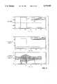
- FIG. 5is a composite graph of various signals produced by the sensor of FIG. 2 versus time.
- FIG. 6is a block diagram showing the timing of information flow in the sensor of FIG. 2.
- FIG. 7is a block and schematic diagram of a temperature sensor according to the invention.
- FIG. 8is a set of composite graphs of an auxiliary signal (upper graph), raw temperature (middle graph), and validated temperature and uncertainty (lower graph) versus time for the instrument of FIG. 7.
- FIG. 9is a set of composite graphs of raw data (upper graph), raw temperature (middle graph), and validated temperature and uncertainty (lower graph) versus time for the instrument of FIG. 7.
- FIGS. 10-1 and 10-2are graph of auxiliary data (FIG. 10-1) and validated temperature and uncertainty (FIG. 10-2) for the instrument of FIG. 7.
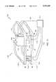
- FIG. 11is a schematic and block diagram of a Coriolis flow meter.
- FIG. 12is pseudocode showing steps performed by the meter of FIG. 11 during each sampling period.
- FIG. 13is pseudocode showing steps performed by the meter of FIG. 11 in determining temperature and associated uncertainty.
- FIG. 14is pseudocode showing steps performed by the meter of FIG. 11 in diagnosing a fault.
- FIGS. 15a-1, 15A-2, 15b-1, 15b-2, 15c-1 and 15c-2are a set of composite graphs showing the effect of a loss of temperature on temperature (FIGS. 15a-1 and 15A-2), density (FIGS. 15b-1 and 15b-2), and mass flow rate (FIGS. 15c-1 and 15c-2) versus time for the meter of FIG. 11.
- FIG. 16is a block diagram of a procedure implemented by the sensor of FIG. 2.
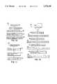
- FIG. 17is a flow chart of a procedure for responding to the detection of a fault.
- FIG. 18is a flow chart of a procedure for detecting a loss of contact fault.
- a plurality of sensors 12monitor parameters of a process 14 and provide signals about the monitored parameters to a data control and management system 16 on a digital communications link 18.
- Digital communications link 18allows bidirectional communication between multiple central processing units 16, sensors 12, and process actuators 20.
- data control and management system 16sends process control signals to process actuators 20 on digital communications link 18.
- process actuators 20respond to process control signals from data control and management system 16 by modifying parameters of process 14.
- data control and management system 16relies on measurement signals from sensors 12 in controlling process 14, measurement signals from sensors 12 need to be accurate and reliable.
- a given sensor 12typically cannot guarantee complete accuracy and reliability; instead, sensor 12 provides data control and management system 16 with indications of the uncertainty (which, in turn, indicates the accuracy) and the reliability of the measurement signals.
- sensor 12includes one or more transducers 22 that monitor the values of parameters of process 14 and provide signals to a transmitter 24.
- Transmitter 24samples the signals from transducers 22 and produces measurement values for the parameters being monitored by transducers 22.
- Transmitter 24validates the measurement values and provides the validated measurement values, along with an indication of the uncertainty of the validated measurement values, to data control and management system 16 via digital communications link 18.
- transmitter 24generates signals indicating the reliability of the validated measurement values provided by sensor 12 and the operational status of sensor 12, and provides these signals to data control and management system 16 via digital communications link 18.
- Transmitter 24generates the signals provided to data control and management system 16 during a sample period and transmits the signals at the end of the sample period.
- the duration of a sample periodis less than one second, but this duration can be adjusted as required by a particular application.
- transmitter 24typically provides four signals to data control and management system 16:
- VMV 26--a validated measurement value of a process parametertransmitter 24's best estimate of the value of the measured parameter
- transmitter 24produces a version of VMV 26, VU 28, and MV status 30 for each process parameter.
- transmitter 24can provide additional information. For example, upon a request by data control and management system 16, transmitter 24 provides detailed diagnostic information 34 about the status of sensor 12. Also, when a measurement has exceeded, or is about to exceed, a predetermined limit, transmitter 24 can send alarm data 35. Typically, different alarm levels can be used to indicate the severity with which the measurement has deviated from the predetermined value.
- VMV 26 and VU 28are numeric values.
- VMV 26could be a temperature measurement valued at 200 degrees and VU 28, the uncertainty of VMV 26, could be 9 degrees. In this case, there is a high probability (typically 95%) that the actual temperature being measured falls within an envelope around VMV 26 and designated by VU 28 (191 degrees to 209 degrees).
- Transmitter 24generates VMV 26 based on a signal produced by transducer 22.
- transmitter 24derives RMV 36, an unvalidated image of the measured process parameter that is based on the signal generated by transducer 22.
- transmitter 24detects no abnormalities in sensor 12
- transmitter 24has nominal confidence in RMV 36 and sets VMV 26 equal to RMV 36.
- transmitter 24when transmitter 24 detects an abnormality in sensor 12, transmitter 24 does not set VMV 26 equal to RMV 36. Instead, transmitter 24 sets VMV 26 to a value that transmitter 24 considers to be a better estimate of the actual parameter than RMV 36. If transmitter 24 detects a fault in sensor 12 that only partially affects the reliability of RMV 36 such that transmitter 24 has reduced confidence in RMV 36, transmitter 24 typically rederives RMV 36 by modifying the parameters used in deriving RMV 36 to account for the fault, and sets VMV 26 equal to the new value of RMV 36. Alternatively, if transmitter 24 detects a fault in sensor 12 which indicates that RMV 36 bears no relation to the actual measured value such that transmitter 24 has zero confidence in RMV 36, transmitter 24 sets VMV 26 to a value based on past performance.
- past performance valuesinclude short term past values, long term past values, and a combination of long and short term past values.
- VMV 26when short term past values are used, VMV 26 can equal the value of VMV 26 had immediately prior to the fault that occurs at time 5.
- VMV 26when long term past value are used, VMV 26 can equal the average value of VMV 26.
- FIG. 4Awhen short term past values are used, VMV 26 can equal the value of VMV 26 had immediately prior to the fault that occurs at time 5.
- long term past valuewhen long term past value are used, VMV 26 can equal the average value of VMV 26.
- VU L and VU Sare the long and short term past values for VU 28 and VMV L and VMV S are the long and short term past values for VMV 26.
- Transmitter 24generates VU 28 based on a raw uncertainty signal, RU 62, that is the result of a dynamic uncertainty analysis of RMV 36. Transmitter 24 performs this uncertainty analysis during each sampling period.
- Mis true (M true ) with a certain level of confidence (typically 95%). This uncertainty is readily expressed in a relative form as a proportion of the measurement (i.e. w M /M).
- a propagation ruleexists for obtaining the uncertainties of arbitrary functions of primary measurements. For example, for an arbitrary function R of variables X, Y, and Z,
- VU 28has a non-zero value even under ideal conditions (i.e., a faultless sensor operating in a controlled, laboratory environment). This is because the measurement produced by a sensor is never completely certain and there is always some potential for error.
- transmitter 24when transmitter 24 detects no abnormalities in sensor 12, transmitter 24 sets VU 28 equal to RU 62. When transmitter 24 detects a fault in sensor 12 that only partially affects the reliability of RMV 36, transmitter 24 typically performs a new uncertainty analysis that accounts for effects of the fault and sets VU 28 equal to the results of this analysis. As with VMV 26, transmitter 24 sets VU 28 to a value based on past performance when transmitter 24 determines that RMV 36 bears no relation to the actual measured value.
- FIGS. 4A-4Cillustrates three exemplary techniques for adjusting VU 28 based on past performance values.
- VU 28can be increased during each sampling period by the maximum observed rate of change of VMV 26. This technique, which tends to give good short term results, eventually produces unrealistic values for VU 28.
- VU 28when VMV 26 is set equal to the long term average of VMV 26, VU 28 can indicate that VMV 26 can take any previous value of VMV 26.
- VMV 26always falls between 0 and 100 and VMV 26 is set to 50, VU 28 is set to 50.
- This techniquetends to give unduly pessimistic short term results, but avoids the long term problems of method FIG. 4A.
- VU 28when VMV 26 is based on a combination of the long and short term past values for VMV 26, VU 28 can be calculated as follows: ##EQU3## where VU L and VU S are the long and short term past values for VU 28.
- MV status 30provides information about how VMV 26 and VU 28 were calculated.
- Transmitter 24produces VMV 26 and VU 28 under all conditions--even when transducers 22 are inoperative.
- data control and management system 16needs to know whether VMV 26 and VU 28 are based on "live" or historical data. For example, if data control and management system 16 were using VMV 26 and VU 28 in feedback control and transducers 22 were inoperative, data control and management system 16 would need to know that VMV 26 and VU 28 were based on past performance.
- MV status 30is based on the expected persistence of any abnormal condition and on the confidence of transmitter 24 in RMV 36.
- the four primary states for MV statusare generated according to Table 1.
- a CLEAR MV status 30occurs when RMV 36 is within a normal range for given process conditions.
- a DAZZLED MV status 30indicates that RMV 36 is quite abnormal, but the abnormality is expected to be of short duration.
- transmitter 24sets MV status 30 to DAZZLED when there is a sudden change in the signal from transducer 22 and transmitter 24 is unable to clearly establish whether this change is due to an as yet undiagnosed sensor fault or to an abrupt change in the variable being measured.
- a BLURRED MV status 30indicates that RMV 36 is abnormal but reasonably related to the parameter being measured. For example, transmitter 24 may set MV status 30 to BLURRED when RMV 36 is a noisy signal.
- a BLIND MV status 30indicates that RMV 36 is completely unreliable and the fault is expected to persist.
- MV status 30is UNVALIDATED when transmitter 24 is not performing validation of VMV 26.
- MV status 30is SECURE when VMV 26 is generated from redundant measurements in which transmitter 24 has nominal confidence.
- Device status 32is a generic, discrete value summarizing the health of sensor 12 that is used primarily by fault detection and maintenance systems. Typically, device status 32 is in one of six states, each of which indicates a different operational status for sensor 12. These states are: GOOD, TESTING, SUSPECT, IMPAIRED, BAD, or CRITICAL. A GOOD device status 32 means that sensor 12 is in nominal condition. A TESTING device status 32 means that sensor 12 is performing a self check, and that this self check may be responsible for any temporary reduction in measurement quality. A SUSPECT device status 32 means that sensor 12 has produced an abnormal response, but transmitter 24 has no detailed fault diagnosis. An IMPAIRED device status 32 means that sensor 12 is suffering from a diagnosed fault that has a minor impact on performance.
- a BAD device status 32means that sensor 12 has seriously malfunctioned and maintenance is required.
- a CRITICAL device status 32means that sensor 12 has malfunctioned to the extent that sensor 12 may cause (or have caused) a hazard such as a leak, fire, or explosion.
- FIG. 5illustrates an example of the relationship between VMV 26, VU 28, MV status 30, and RMV 36.
- FIG. 5illustrates a preferred method of displaying the relationship between VMV 26 and VU 28 both during normal operation and when a fault has occurred:
- VU 28is shown both as a separate signal and as an envelope surrounding VMV 26 (line 38 indicates the sum of VMV 26 and VU 28 and line 40 indicates the difference between VMV 26 and VU 28).
- line 38indicates the sum of VMV 26 and VU 28
- line 40indicates the difference between VMV 26 and VU 28.
- RMV 36is a periodic signal whose amplitude falls within an expected range.
- VMV 26equals RMV 36
- MV status 30is CLEAR
- VU 28remains at a constant "normal" level that corresponds to RU 62, the uncertainty under normal operating conditions (with line 42 representing a zero value for VU 28).
- RU 62is assumed to have a constant value.
- RMV 36begins to increase at a rate that substantially exceeds an expected rate of change for RMV 36.
- Transmitter 24takes a number of actions in response to this unexplained phenomenon. First, transmitter 24 changes MV status 30 to DAZZLED. Next, transmitter 24, which is basing VMV 26 and VU 28 on short term past performance values in this example, maintains VMV 26 at the value that VMV 26 had just before the sudden increase in RMV 36 at time T2. Finally, transmitter 24 begins to increase VU 28 at a constant rate that equals the maximum rate of increase of VMV 26 during normal operation. The progressive increase in the value of VU 28 over time reflects increasing uncertainty of the value of the measurement in the absence of up to date valid transducer data caused by sensor 12 being DAZZLED.
- RMV 36continues to increase until time T3. At time T3, RMV 36 stops increasing and remains at a constant level. Because the value of RMV 36 now exceeds expected values, transmitter 24 does not change VMV 26 or MV status 30, and continues to increase VU 28 at a constant rate. At time T4, RMV 36 begins to decrease. Because the value of RMV 36 still exceeds expected values, transmitter 24 makes no changes to VMV 26 or MV status 30, and continues to increase VU 28 at a constant rate.
- RMV 36begins to operate as expected.
- transmitter 24changes MV status 30 to BLURRED and begins to merge VMV 26 with RMV 36 using, for example, the following equation:
- transmitter 24initializes a recovery timeout period. Finally, transmitter 24 begins to decrease VU 28 by merging VU 28 with RU 62 using, for example, the following equation:
- VU n+1is the value of VU 28 for the current sample
- VU nis the value of VU 28 generated in the previous sample
- RU n+1is the value of RU 62 for the current sample.
- transmitter 24determines that the recovery timeout period has expired and changes MV status 30 to CLEAR. Because transmitter 24 now has nominal confidence in RMV 36, transmitter 24 sets VU 28 equal to RU 62.
- MV status 30can only be DAZZLED for a limited "timeout" period. Thus, if RMV 36 remained at unexpected levels, the timeout period would eventually expire, and transmitter 24 would change MV status 30 to BLIND.
- transmitter 24uses several sources of information, each of which is discussed below, in generating VMV 26, VU 28, MV status 30, device status 32, diagnostic information 34, and alarm data 35.
- Raw data 44the basic measurement information available to transmitter 24, is typically an electrical image of the output of one or more transducers 22 (e.g., the frequency of oscillation or the resistance of a transducer 22).
- Raw data 44contains the maximum information available about the response of transducer 22 and is therefore a rich source of information for statistical tests to detect sensor faults.
- knowledge of expected process behaviorcannot be applied readily to raw data 44 and is more appropriately applied to statistics based on RMV 36.
- transmitter 24can link the expected (no-fault) behavior of RMV 36 to the expected behavior of the process parameter associated with RMV 36.
- Transmitter 24derives RMV 36 from raw data 44 by conventional processing. For example, if raw data 44 corresponds to the resistance of a transducer 22 and RMV 36 corresponds to temperature, transmitter 24 derives RMV 36 based on raw data 44 in light of known effects of temperature on the resistance of transducer 22. Often, transmitter 24 filters RMV 36 to reduce the effect of sensor noise and high frequency process disturbances. When filtering occurs, RMV 36 contains less information than raw data 44.
- raw data 44 and RMV 36are complementary sources of information. While raw data 44 has more information content than RMV 36, RMV 36 is more easily compared with expected process behavior. Thus, raw data 44 and RMV 36 each offer useful information to transmitter 24.
- Auxiliary data 46is provided by auxiliary signals within sensor 12.
- Auxiliary signalsthough not directly related to raw data 44 or RMV 36, give useful information about the health or performance of sensor 12. For example, statistical tests to identify characteristic sensor or process behavior may be associated with particular auxiliary signals.
- Examples of auxiliary signalsinclude the electrical properties of components within sensor 12 (e.g., signal levels at the input or output stages of power amplifiers) and hardware error information 50.
- Hardware error information 50is a special, preprocessed form of auxiliary information generated by digital components within sensor 12, requiring little or no processing or interpretation. For example, a memory checksum error in a memory component of transmitter 24 would constitute hardware error information 50.
- transmitter 24uses information from data control and management system 16 in generating output signals.
- Data control and management system 16is known as the "Next Level Up” (“NLU"), and information from data control and management system 16 is known as NLU information 48.
- NLUNext Level Up
- a difficulty associated with having transmitter 24 validate the output of sensor 12is that transmitter 24 may have insufficient information to reach a valid conclusion. For example, transmitter 24 may be unable to distinguish between certain types of sensor faults (e.g., drift errors that cause the output of the sensor to change over time for a given input) and legitimate process changes. In these situations, transmitter 24 may refer to NLU information 48 for clarification.
- Data control and management system 16which has access to additional information, including data from other sensors 12, provides transmitter 24 with the information needed to distinguish between process changes and sensor drift.
- Transmitter 24may request NLU information 48 such as anticipated process limits through standard requests to data control and management system 16.
- data control and management system 16can provide unsolicited information, such as indications of changes in process behavior that will change the process parameters being measured by transducers 22, to transmitter 24. For example, if process 14 operates in a number of phases that each have distinct characteristics, data control and management system 16 can notify transmitter 24 when the phase of process 14 changes.
- Application knowledge base information 52allows transmitter 24 to estimate a "wear and tear" effect on sensor performance.
- Application knowledge base information 52describes the relationship between signals and sensor characteristics over time.
- sensorsare known to degrade much more rapidly under certain conditions (e.g., at extremes of their operating range). For example, if a normal range pH probe is exposed to more than about 12 pH for as little as an hour, the probe may become alkali-conditioned and fail to respond when the solution becomes more acidic.
- Application knowledge base information 52also includes factors such as the time elapsed since the last calibration or last maintenance of sensor 12.
- Sensor/process stimulus information 54provides information about a known stimulus applied to the process or part of a sensor. Sensor/process stimulus information 54 is used in implementing procedures for testing sensor 12. A known stimulus is applied to process 14 or sensor 12 and the response generated by sensor 12 is compared with an expected response. For example, sensor/process stimulus information 54 could describe a known force that has been introduced to a pressure transducer. Sensor/process stimulus information 54 is generated by transmitter 24 (i.e., as part of a self-test initiated by transmitter 24) or sent by data control and management system 16 as NLU information 48. When testing disables the measuring capability of sensor 12, transmitter 24 sets the MV status 30 of each disabled measurement to DAZZLED, bases VMV 26 and VU 28 on past performance, and sets device status 32 to TESTING.
- FIG. 3also shows the functional units of transmitter 24.
- a diagnostic state machine 56processes all of the information available to transmitter 24 and determines the diagnostic state 58 of sensor 12.
- Diagnostic state 58is the central piece of information used by diagnostic state machine 56 in deriving VMV 26, VU 28, MV status 30, and device status 32. Because diagnostic state 58 may itself be helpful to users performing maintenance on sensor 12, it is the basis of diagnostic information 34, which is output upon a request by data control and management system 16.
- transmitter 24performs the following operations during each sampling period. After getting raw data 44 from transducer 22 (step 72), diagnostic state machine 56 propagates raw data 44 through a set of device equations 60 to generate RMV 36 (step 74). At the same time, transmitter 24 dynamically calculates RU 62 using an uncertainty analysis 64 based on device equations 60 and calibration data 66 in accordance with the established standards discussed above (step 74). In calculating RU 62, transmitter 24 assumes that no fault has occurred. RU 62 has a non-zero value under all operating conditions. Generally, RU 62 increases under other than ideal conditions.
- diagnostic state machine 56obtains other information (step 76) and, based on the other information, raw data 44, RMV 36, and RU 62, calculates statistics or performs pattern matching to determine if sensor 12 is operating correctly (step 78). Based on the results of step 78, diagnostic state machine 56 updates diagnostic state 58 (step 80).
- diagnostic state machine 56modifies (68) RMV 36 based on diagnostic state 58 to produce VMV 26. Essentially, diagnostic state machine 56 recalculates RMV 36 after modifying the parameters used in the calculation to account for diagnostic state 58 and sets VMV 26 equal to the new RMV 36 (step 82). Thus, under normal operating conditions (when diagnostic state 58 does not require modification of any parameters), VMV 26 typically equals RMV 36.
- diagnostic state machine 56modifies (70) RU 62 based on diagnostic state 58 to produce VU 28.
- diagnostic state machine 56recalculates RU 62 after modifying the parameters used in the calculation to account for diagnostic state 58 and sets VU 28 equal to the new RU 62 (step 82).
- VU 28typically equals RU 62 under normal operating conditions. Under other conditions, VU 28 typically exceeds RU 62.
- diagnostic state machine 56selects MV status 30 (step 84) and device status 32 (step 86) based on diagnostic state 58 and via either calculations or a lookup table. If necessary, diagnostic state machine 56 sends alarm data 35 by updating alarm flags (step 88). Also, if data control and management system 16 has requested it, diagnostic state machine 56 generates diagnostic information 34 based on diagnostic state 58 (step 90).
- thermocouple 102includes two dissimilar metals in contact and produces a voltage, V Diff , between two terminals 108 and 110.
- V Diffis proportional to the difference between the temperature of a sensing junction 112 and a reference junction 114.
- the sum of V Diff and V Compa voltage proportional to the difference between the temperature of reference junction 114 and zero degrees, equals V Temp , a voltage proportional to the difference between the temperature of sensing junction 112 and zero degrees.
- V diffis amplified by amplifier 116 and V comp is generated by temperature sensor 118 and amplified by amplifier 120.
- the output 117 of amplifier 116 and the output 121 of amplifier 120are then supplied to an analog-to-digital convertor ("ADC") 122 in processor 106.
- ADCanalog-to-digital convertor
- Processor 106uses amplifier outputs 117, 121, and other available information, to generate diagnostic state 58, RMV 36, and RU 62. Based on these signals, processor 106 generates VMV 26, VU 28, MV status 30, device status 32, alarm data 35, and, when requested, diagnostic information 34.
- self-validating temperature sensor 100responds to a loss of power to amplifiers 116, 120 as described below.
- VMV 26equals RMV 36, which processor 106 generates based on the sum of outputs 117, 121.
- VU 28equals RU 62, and indicates the uncertainty of VMV 26.
- MV status 30is CLEAR.
- V Diff and V Compboth go to zero volts, which results in an RMV 36 of about negative 55° C. (for a particular transmitter design).
- Processor 106detects the loss of power when power monitor 134, a digital auxiliary signal, switches from one to zero in response to the loss of power.
- Processor 106sets diagnostic state 58 to indicate that processor 106 has zero confidence in RMV 36.
- processor 106sets VMV 26 and VU 28 to a combination of the long and short term past values for VMV 26 and VU 28 respectively as described above.
- processor 106signals the severity and expected long term duration of the sensor fault by setting MV status 30 to BLIND.
- processor 106When the power supply is restored at time 36, processor 106 detects the change in power monitor 134 from zero to one and sets MV status 30 to BLURRED.
- the "live" data from RMV 36is merged with the previous value of VMV 26 as described above to give a new value for VMV 26.
- RU 62is merged with the previous value of VU 28 to give a decreasing value for VU 28.
- processor 106also initializes a recovery timer.
- Processor 106generates VMV 26 and VU 28 by merging past values of VMV 26 and VU 28 with, respectively, RMV 36 and RU 62 until the recovery timer expires at time 56. (In this example, the recovery timer was set for 20 seconds.) At that time, processor 106 sets MV status to CLEAR, sets VMV 26 equal to RMV 36, and sets VU 28 equal to RU 62.
- an open circuit faultoccurs at time 13 when thermocouple 102 is disconnected from transmitter 104.
- RMV 36is around 130° C., which corresponds to a normal value for output 121 but an abnormally high value for output 117 due to saturation of amplifier 116.
- Pull-up resistor 136causes saturation of amplifier 116 in the presence of an open circuit fault.
- processor 106sets diagnostic state 58 to indicate zero confidence in RMV 36 and sets MV status 30 to DAZZLED.
- Processor 106then generates VMV 26 and VU 28 based on a combination of the long and short term past values as described above.
- processor 106connects thermocouple 102 to voltage source 124 via switch 126 and monitors the voltage 130 produced across a resistor 128. Because of the open circuit, no current flows in resistor 128 and voltage 130 is zero volts. From this, processor 106 confirms the open circuit fault and sets MV status 30 to BLIND.
- Processor 106responds by setting diagnostic state 58 to indicate reduced confidence in RMV 36 (rather than no confidence), sets MV status 30 to BLURRED, and initializes a recovery timer.
- processor 106generates VMV 26 and VU 28 by merging past values of VMV 26 and VU 28 with, respectively, RMV 36 and RU 62 until the recovery timer expires at time 47 (where the recovery timer was set for 20 seconds). At that time, processor 106 sets MV status to CLEAR, sets VMV 26 equal to RMV 36, and sets VU 28 equal to RU 62.
- a loss of contact faultoccurs when sensing junction 112 loses contact with the process element of which the temperature is being measured. Because a loss of contact fault does not produce an abnormal change in RMV 36, sensor 100 cannot readily detect the fault.
- sensor 100uses current injection tests to detect loss of contact faults.
- sensor 100connects thermocouple 102 to voltage source 124 for a predetermined period and measures the effect on output 117. (The value of output 117 before thermocouple 102 is connected to voltage source 124 is compared to the value after disconnection.)
- a loss of contact faultoccurs at time 12 and the measured temperature drops by about seven degrees. Because this is within normal operating parameters, sensor 100 does not immediately recognize the fault, and, instead, adjusts VMV 26 and maintains MV status 30 as CLEAR.
- processor 106begins a current injection test. Because amplifier 116 does not read "live” data during the test, processor 106 sets MV status 30 to DAZZLED and generates VMV 26 and VU 28 based on past performance as discussed above. At time 33, processor 106 determines that the fault has occurred and sets MV status 30 to BLURRED. (Processor 106 assumes that, though contact has been lost, the temperature sensed by thermocouple 102 still approximates the actual temperature.)
- processor 106interprets the sudden change in output 117 as a spike and temporarily sets MV status 30 to DAZZLED.
- processor 106sets MV status 30 back to BLURRED. (Processor 106 does not set MV status 30 to CLEAR because processor 106 has not detected the removal of the fault condition.)
- processor 106begins another current injection test and sets MV status 30 to DAZZLED.
- processor 106determines that contact has been reestablished and, in response, sets MV status to BLURRED and initializes a recovery timer.
- the recovery timer(which was set to 25 seconds) expires and processor 106 sets MV status to CLEAR.
- Flow meter 150measures three process parameters: mass flow rate, density, and temperature. Mass flow is measured directly using the principle of Coriolis acceleration, without needing to rely on external pressure, temperature, or specific gravity measurements.
- flow meter 150consists of a flowtube 152 that is connected to a transmitter 154 by cables 156.
- Flowtube 152includes a body 158 to which is connected an input pipe 160 and an output pipe 162.
- Two parallel pipe loops 164, 166extend from body 158.
- Body 158contains passages which lead a process fluid from input pipe 160 to the beginning of loop 164, from the end of loop 164 to the beginning of loop 166 and from the end of loop 166 to output pipe 162 (the broken arrows in FIG. 11 show the direction of flow in loops 164, 166).
- Transmitter 154causes loops 164, 166 to pivotally oscillate about their axes of symmetry Y'-Z' and Y-Z by supplying anti-phase sinusoidal signals to electromagnetic drivers 168, 170. Transmitter 154 uses feedback to maintain the signals to drivers 168, 170 at the resonant frequency of loops 164, 166. Transmitter 154 then detects movement of loops 164, 166 via sensors 172, 174, which each produce a voltage that is proportional to the instantaneous velocity between loops 164, 166. Transmitter 154 adjusts the amplitude of the signals to drivers 168, 170 to maintain the average amplitude of the voltages produces by sensors 172, 174 at a constant level.
- Transmitter 154measures mass flow rate, density, and temperature in the following manner.
- transmitter 154measures the mass flow rate of the process fluid by monitoring the effect of Coriolis forces on loops 164, 166. Coriolis forces acting on sections G'-H' and G-H of oscillating loops 164, 166 cause deflections of loops 164, 166. These deflections result in a phase angle difference between the voltages produced by sensors 172, 174 that is proportional to the mass flow rate.
- transmitter 154determines the density of the process fluid from the frequency of oscillation of loops 164, 166 (which equals the frequency of the signals supplied to drivers 168, 170). The density of the process fluid is inversely proportional to the square of the drive frequency.
- transmitter 154measures the temperature of the process fluid via a temperature sensor 176 located in body 158. Typically, temperature sensor 176 is an RTD device with a resistance that is temperature dependent.
- the raw data availableare the frequency 44a of a signal coming out of temperature sensor 176 (the frequency is proportional to the resistance of temperature sensor 176), frequency 44b of the drive signals applied to drivers 168, 170, and the voltage outputs 44c of sensors 172, 174.
- transmitter 154derives three RMVs: the temperature of the process fluid 36a, the density of the process fluid 36b, and the mass flow rate 36c (derived from the phase angle between the sensor signals).
- transmitter 154performs uncertainty analyses to produces three RUs (62a, 62b, 62c), each indicating the uncertainty of a corresponding RMV 36.
- transmitter 154After generating RMVs 36a, 36b and 36c and RUs 62a, 62b and 62c, transmitter 154 determines the diagnostic state 58 of flow meter 150. This determination is based on raw data 44a, 44b and 44c, RMVs 36a, 36b and 36c, RUs 62a, 62b and 62c, and auxiliary data 46. Based on diagnostic state 58, transmitter 154 adjusts the parameters used in calculating RMVs 36a, 36b and 36c and RUs 62a, 62b and 62c and recalculates these values.
- Transmitter 154then outputs the recalculated RMVs 36a, 36b and 36c and RUs 62a, 62b and 62c as VMVs 26a, 26b and 26c and VUs 28a, 28b and 28c. Transmitter 154 also outputs a MV status 30a corresponding to temperature, a MV status 30b corresponding to density, and a MV status 30c corresponding to mass flow rate. Finally, transmitter 154 outputs a single device status 32 corresponding to the status of flow meter 150.
- the procedure performed by transmitter 154 during each sample periodcan be implemented in software.
- An example of software for implementing of a self-validating Coriolis meter 150is included in microfiche appendix 1.
- an example of software for implementing a self-validating temperature sensor 100 as described aboveis included in microfiche appendix 2.
- the software in appendices 1 and 2may be implemented on any processor that supports a structured programming language. In an alternative approach, the procedure could be implemented using hard-wired circuitry.
- transmitter 154gets raw data 44a, 44b and 44c from flowtube 152 (step 200). Transmitter 154 then calculates RMVs 36a, 36b and 36c and RUs 62a, 62b and 62c (steps 202-206). The pseudocode for calculating RMV 36a and RU 62a is shown in FIG. 13 and is discussed below. Next, transmitter 154 examines all available information (step 208) and determines diagnostic state 58, MV statuses 30a, 30b and 30c, and device status 32 (step 210).
- transmitter 154Based on diagnostic state 58, transmitter 154 corrects the parameters used in calculating RMV 36a, 36b and 36c and RU 62a, 62b and 62c (step 212). Transmitter 154 then calculates VMVs 26a, 26b and 26c and VUs 28a, 28b and 28c (steps 214-218) using the procedure with which RMVs 36a, 36b and 36c and RUs 62a, 62b and 62c were calculated and corrected parameters.
- transmitter 154calculates RMV 36a and RU 62a as follows. First, transmitter 154 calculates the resistance "R" of temperature sensor 176 (step 250). Transmitter 154 then calculates the uncertainty "d -- R” of R based on an uncertainty analysis of the equation used to calculate R (step 252). Next, transmitter 154 calculates "temperature” (step 254), and sets RMV 36a equal to temperature. Finally, transmitter 154 calculates the uncertainty "d -- temperature” of temperature (step 256), and sets RU 62a equal to d -- temperature. Thus, as a first pass RMV 36a and RU 62a equal the measured temperature and its corresponding uncertainty.
- transmitter 154modifies any of the parameters, uncertainties, and/or raw data (e.g., RK1, d -- RK1, f -- RTD) used in calculating temperature and d -- temperature to reflect the impact of an expected fault. Transmitter 154 then reperforms the procedure illustrated in FIG. 13 using the modified information and sets VMV 26a and VU 28a equal to the new values for temperature and d -- temperature. Alternatively, if transmitter 154 determines that the fault is too severe, transmitter 154 may set VMV 26a and VU 28a based on historical data.
- raw datae.g., RK1, d -- RK1, f -- RTD
- FIG. 14illustrates the procedure used by transmitter 154 to detect and respond to a loss of input from temperature sensor 176.
- Transmitter 154maintains a variable, RTD -- input -- state, that indicates the current status of the input from temperature sensor 176.
- transmitter 154checks RTD -- input state (step 300).
- RTD -- input -- stateequals RTD -- INPUT -- OK (step 302), which indicates that the input from temperature sensor 176 was functioning normally during the previous sample period
- transmitter 154checks the resistance of temperature sensor 176 (step 304). If the resistance is less than 80 ohms, this indicates that the connection between transmitter 154 and temperature sensor 176 has been lost. In response, transmitter 154 sets RTD -- input -- state to RTD -- INPUT -- LOST (step 306). Transmitter 154 then checks the value of RTD -- spike -- state, which indicates whether transmitter 154 had sensed a spike in the output from temperature sensor 176 during the previous sample (step 308). If RTD -- spike -- state indicates that a spike had occurred, transmitter 154 resets RTD -- input -- state to indicate no spike (step 310). (A spike is a less serious fault and is mooted by the loss of connection.)
- transmitter 154checks the resistance of temperature sensor 176. If the resistance is less than 100 ohms (step 314), this indicates that connection with temperature sensor 176 is still lost. (Different resistance values are used in steps 304 and 314 to avoid intermittent switching of RTD -- input -- state if, for example, the resistance fluctuates between 79 and 81 ohms.) If connection is lost, transmitter 154 sets MV status 30a, which corresponds to temperature, to BLIND (step 316) and substitutes historical information (step 318) about temperature for use in the recalculation steps (steps 214-218 of FIG. 12).
- transmitter 154sets MV statuses 30b (step 320) and 30c (step 322) to BLURRED. If the resistance is greater than 100 ohms (step 324), transmitter 154 sets RTD -- input state to RTD -- INPUT -- RECOVER, to indicate that connection has been reestablished (step 326). At this time, transmitter 154 initializes a recovery timer by setting RTD -- input -- count equal to zero (step 328).
- transmitter 154merges the past and present values for temperature as discussed above (step 332). Transmitter 154 then checks to see if the recovery timeout period has expired (step 334). If it has, transmitter 154 sets RTD -- input -- state to RTD -- INPUT -- OK (step 336). If it has not (step 338), transmitter 154 sets MV status 30a to BLURRED (step 340) and increments RTD -- input -- count (step 342).
- FIGS. 15a-1, 15A-2, 15b-1, 15b-2, 15c-1 and 15c-2illustrates the response of flow meter 150 to a loss of input from temperature sensor 176. At time 9, the loss of input occurs and the unvalidated temperature measurement, RMV 36a, begins to rapidly drop.
- transmitter 154sets diagnostic state 58 to indicate that a spike in the temperature input has occurred, and, in response, changes MV status 30a to DAZZLED, modifies VMV 26a and VU 28a based on past performance as discussed above, and leaves MV statuses 30b and 30c, VMVs 26b and 26c, and VUs 28b and 28c unchanged (though, because density and mass flow rate are partially dependent on temperature, VMVs 26b and 26c and VUs 28b and 28c include the changes to VMV 26a and VU 28a).
- the resistance of temperature sensor 176drops sufficiently low that transmitter 154 sets diagnostic state 58 to indicate that a loss of temperature input has occurred, and, in response, changes MV status 30a to BLIND, continues to base VMV 26a and VU 28a on past performance, changes MV statuses 30b and 30c to BLURRED, and leaves VMVs 26b and 26c unchanged. Because the uncertainties of density and mass flow are based in part on the uncertainty of temperature, VUs 28b and 28c will increase to reflect the increase in VU 28a.
- the resistance of temperature sensor 176increases to a sufficient level so that transmitter 154 sets diagnostic state 58 to indicates that temperature input has been recovered, and, in response, changes MV status 30a to BLURRED, initializes a recovery timer, begins merging past and present values for VMV 26a and VU 28a, and changes MV statuses 30b and 30c to CLEAR.
- the recovery timerexpires, and transmitter 154 sets diagnostic state 58 to indicate that the temperature input is fully recovered, and, in response, changes MV status 30a to CLEAR and bases VMV 26a and VU 28a on RMV 36a and RU 62a.
- a sensor 12implements a procedure 350.
- the sensorreceives a data signal related to the value of a variable (step 352), and, based on the data signal, estimates a measurement of the variable (step 354). Thereafter, the sensor generates a first output signal (step 356), which can be related to the estimated measurement of the variable. Finally, the sensor performs an uncertainty analysis on the first output signal (step 358) and generates a second output signal based on the uncertainty analysis (step 360).
- a sensormay respond to the detection of a fault according to a procedure 400.
- the sensordetermines whether the occurrence of a fault has been detected in the source of a measurement (step 405). For example, as shown in FIG. 18 and discussed above, when the sensor includes a temperature transducer, the sensor may detect a loss of contact fault using a procedure 500.
- the sensorstores an output of the temperature transducer (step 505) and connects the temperature transducer to a voltage source for a predetermined time period (step 510). After the predetermined time period expires, the sensor compares the stored output with the current output of the temperature transducer (step 515) and indicates that a loss of contact fault has been detected based on the comparison (step 520).
- the sensorproduces a first estimate of the measurement (step 410).
- the first estimatemay be a mean value of the measurement during a time interval that includes a short term past value of the measurement.
- the time intervalmay include a value of the measurement immediately prior to the occurrence of the fault.
- the sensoralso produces an uncertainty measure for the first estimate (step 415). Initially, the uncertainty measure may indicate that the measurement can have any value observed for the measurement during the time interval. The sensor may also account for a reduction in reliability of the first estimate due to a time difference between the current time and a time at the end of the time interval.
- the senormay adjust the uncertainty measure for the first estimate by multiplying the time difference between the current time and the time at the end of the time interval by a maximum observed rate of change of the measurement.
- the sensorthen produces a second estimate (step 420) and a related uncertainty measure (step 425) using the approach described above for the first estimate and uncertainty measure.
- the second estimatemay be based on long term past values of the measurement.
- the sensorcombines the multiple estimates of the measurement to produce a combined estimate for the measurement (step 430).
- the sensormay combine the estimates by weighting the estimates according to their associated uncertainty measures.
- the sensormay multiply the first estimate by the second uncertainty measure squared divided by a sum of the second uncertainty measure squared and the first uncertainty measure squared and add a result of this multiplication to a result of multiplying the second estimate by the first uncertainty measure squared divided by a sum of the second uncertainty measure squared and the first uncertainty measure squared: ##EQU4##
- the sensoralso combines uncertainty measures for each of the multiple estimates to produce an uncertainty measure for the combined estimate for the measurement (step 435).
- the sensormay do so by multiplying the second uncertainty measure by the first uncertainty measure and dividing a result of the multiplication by a square root of a sum of the second uncertainty measure squared and the first uncertainty measure squared: ##EQU5##
- the sensorprovides the combined estimate for the measurement as a value for the measurement at a current time (step 440) and the uncertainty measure for the combined estimate as an indication of the validity of the value for the measurement at the current time (step 445).
Landscapes
- Physics & Mathematics (AREA)
- General Physics & Mathematics (AREA)
- Fluid Mechanics (AREA)
- Engineering & Computer Science (AREA)
- Signal Processing (AREA)
- Arrangements For Transmission Of Measured Signals (AREA)
- Testing Or Calibration Of Command Recording Devices (AREA)
- Measuring Volume Flow (AREA)
- Measuring Temperature Or Quantity Of Heat (AREA)
- Indication And Recording Devices For Special Purposes And Tariff Metering Devices (AREA)
Abstract
Description
M.sub.true ε[M-w.sub.M, M+w.sub.M ]
R=R(X,Y,Z)
[w.sub.R /R].sup.2 =[∂R/∂X].sup.2 [w.sub.x /R].sup.2 +[∂R/∂Y].sup.2 [w.sub.Y /R].sup.2 +[∂R/∂Z].sup.2 [w.sub.Z /R].sup.2
R=x-y,
w.sub.R /R=[(x/(x-y)*w.sub.x /x).sup.2 +(y/(x-y)*w.sub.y /y).sup.2 ].sup.1/2.
R=(1/(1+z)).sup.1/2,
w.sub.R /R=w.sub.z /2(1+z).
TABLE 1 ______________________________________ Expected Confidence Persistence in RMV MV Status ______________________________________ not applicable nominal CLEAR not applicable reduced BLURRED short zero DAZZLED long zero BLIND ______________________________________
VMV.sub.n+1 =0.95* VMV.sub.n +0.05* RMV.sub.n+1
VU.sub.n+1.sup.2 =0.95.sup.2 *VU.sub.n.sup.2 +0.05.sup.2 *RU.sub.n+1.sup.2
Claims (21)
Priority Applications (2)
| Application Number | Priority Date | Filing Date | Title |
|---|---|---|---|
| US08/406,805US5570300A (en) | 1992-04-22 | 1995-03-20 | Self-validating sensors |
| US08/705,982US5774378A (en) | 1993-04-21 | 1996-08-30 | Self-validating sensors |
Applications Claiming Priority (4)
| Application Number | Priority Date | Filing Date | Title |
|---|---|---|---|
| GB929208704AGB9208704D0 (en) | 1992-04-22 | 1992-04-22 | Improvements in and relating to sensor units |
| GB9208704 | 1992-04-22 | ||
| US5119293A | 1993-04-21 | 1993-04-21 | |
| US08/406,805US5570300A (en) | 1992-04-22 | 1995-03-20 | Self-validating sensors |
Related Parent Applications (1)
| Application Number | Title | Priority Date | Filing Date |
|---|---|---|---|
| US5119293AContinuation | 1992-04-22 | 1993-04-21 |
Related Child Applications (1)
| Application Number | Title | Priority Date | Filing Date |
|---|---|---|---|
| US08/705,982Continuation-In-PartUS5774378A (en) | 1993-04-21 | 1996-08-30 | Self-validating sensors |
Publications (1)
| Publication Number | Publication Date |
|---|---|
| US5570300Atrue US5570300A (en) | 1996-10-29 |
Family
ID=10714379
Family Applications (1)
| Application Number | Title | Priority Date | Filing Date |
|---|---|---|---|
| US08/406,805Expired - LifetimeUS5570300A (en) | 1992-04-22 | 1995-03-20 | Self-validating sensors |
Country Status (7)
| Country | Link |
|---|---|
| US (1) | US5570300A (en) |
| EP (1) | EP0646234B1 (en) |
| JP (1) | JP3425148B2 (en) |
| AU (1) | AU4109093A (en) |
| DE (1) | DE69325585T2 (en) |
| GB (1) | GB9208704D0 (en) |
| WO (1) | WO1993021505A1 (en) |
Cited By (146)
| Publication number | Priority date | Publication date | Assignee | Title |
|---|---|---|---|---|
| US5774378A (en)* | 1993-04-21 | 1998-06-30 | The Foxboro Company | Self-validating sensors |
| US5828567A (en)* | 1996-11-07 | 1998-10-27 | Rosemount Inc. | Diagnostics for resistance based transmitter |
| US5864773A (en)* | 1995-11-03 | 1999-01-26 | Texas Instruments Incorporated | Virtual sensor based monitoring and fault detection/classification system and method for semiconductor processing equipment |
| US5956663A (en)* | 1996-11-07 | 1999-09-21 | Rosemount, Inc. | Signal processing technique which separates signal components in a sensor for sensor diagnostics |
| US6007780A (en)* | 1996-12-12 | 1999-12-28 | Johnson & Johnson | Control programming arrangement |
| US6017143A (en)* | 1996-03-28 | 2000-01-25 | Rosemount Inc. | Device in a process system for detecting events |
| US6047220A (en)* | 1996-12-31 | 2000-04-04 | Rosemount Inc. | Device in a process system for validating a control signal from a field device |
| WO2000019175A1 (en)* | 1998-09-30 | 2000-04-06 | Micro Motion, Inc. | Transient bubble remediation in coriolis flowmeters |
| US6073089A (en)* | 1997-10-22 | 2000-06-06 | Baker; Michelle | Systems and methods for adaptive profiling, fault detection, and alert generation in a changing environment which is measurable by at least two different measures of state |
| WO2001003099A1 (en)* | 1999-07-01 | 2001-01-11 | Rosemount, Inc. | Low power two-wire self validating temperature transmitter |
| WO2001040882A1 (en)* | 1999-12-03 | 2001-06-07 | The Foxboro Company | Process control system with automatic fault-avoidance |
| US6298454B1 (en) | 1999-02-22 | 2001-10-02 | Fisher-Rosemount Systems, Inc. | Diagnostics in a process control system |
| US6311136B1 (en) | 1997-11-26 | 2001-10-30 | Invensys Systems, Inc. | Digital flowmeter |
| US6356191B1 (en) | 1999-06-17 | 2002-03-12 | Rosemount Inc. | Error compensation for a process fluid temperature transmitter |
| US6356857B1 (en)* | 1998-08-17 | 2002-03-12 | Aspen Technology, Inc. | Sensor validation apparatus and method |
| US6370448B1 (en) | 1997-10-13 | 2002-04-09 | Rosemount Inc. | Communication technique for field devices in industrial processes |
| US20020042694A1 (en)* | 2000-03-23 | 2002-04-11 | Henry Manus P. | Process monitoring and control using self-validating sensors |
| US6401046B1 (en)* | 1999-09-22 | 2002-06-04 | Visteon Global Technologies, Inc. | Modulated interface for remote signals |
| US6424930B1 (en) | 1999-04-23 | 2002-07-23 | Graeme G. Wood | Distributed processing system for component lifetime prediction |
| US6434504B1 (en) | 1996-11-07 | 2002-08-13 | Rosemount Inc. | Resistance based process control device diagnostics |
| US6449574B1 (en) | 1996-11-07 | 2002-09-10 | Micro Motion, Inc. | Resistance based process control device diagnostics |
| US20020129661A1 (en)* | 2001-01-16 | 2002-09-19 | Clarke David W. | Vortex flowmeter |
| US6505517B1 (en) | 1999-07-23 | 2003-01-14 | Rosemount Inc. | High accuracy signal processing for magnetic flowmeter |
| US6505519B2 (en) | 2000-03-23 | 2003-01-14 | Invensys Systems, Inc. | Correcting for two-phase flow in a digital flowmeter |
| US20030028334A1 (en)* | 2001-06-26 | 2003-02-06 | Tarek Ghaoud | Evaluating a vortex flow-meter signal |
| US6519546B1 (en) | 1996-11-07 | 2003-02-11 | Rosemount Inc. | Auto correcting temperature transmitter with resistance based sensor |
| WO2003023619A1 (en)* | 2001-09-07 | 2003-03-20 | Andean Mining Technologies S.A. | Method and apparatus for sensing and transmitting process parameters |
| US6539267B1 (en) | 1996-03-28 | 2003-03-25 | Rosemount Inc. | Device in a process system for determining statistical parameter |
| US6556145B1 (en) | 1999-09-24 | 2003-04-29 | Rosemount Inc. | Two-wire fluid temperature transmitter with thermocouple diagnostics |
| US20030088381A1 (en)* | 2001-06-25 | 2003-05-08 | Henry Manus P. | Sensor fusion using self evaluating process sensors |
| US20030109937A1 (en)* | 2001-12-06 | 2003-06-12 | Martin Zielinski | Intrinsically safe field maintenance tool |
| US6594620B1 (en)* | 1998-08-17 | 2003-07-15 | Aspen Technology, Inc. | Sensor validation apparatus and method |
| US6601005B1 (en) | 1996-11-07 | 2003-07-29 | Rosemount Inc. | Process device diagnostics using process variable sensor signal |
| US6611775B1 (en) | 1998-12-10 | 2003-08-26 | Rosemount Inc. | Electrode leakage diagnostics in a magnetic flow meter |
| US6615149B1 (en) | 1998-12-10 | 2003-09-02 | Rosemount Inc. | Spectral diagnostics in a magnetic flow meter |
| US6629059B2 (en) | 2001-05-14 | 2003-09-30 | Fisher-Rosemount Systems, Inc. | Hand held diagnostic and communication device with automatic bus detection |
| US6629448B1 (en) | 2000-02-25 | 2003-10-07 | Seagate Technology Llc | In-situ testing of a MEMS accelerometer in a disc storage system |
| US6633782B1 (en) | 1999-02-22 | 2003-10-14 | Fisher-Rosemount Systems, Inc. | Diagnostic expert in a process control system |
| US20030204373A1 (en)* | 2001-12-06 | 2003-10-30 | Fisher-Rosemount Systems, Inc. | Wireless communication method between handheld field maintenance tools |
| US20030212509A1 (en)* | 2002-03-29 | 2003-11-13 | Henry Manus P. | Startup and operational techniques for a digital flowmeter |
| US6654697B1 (en) | 1996-03-28 | 2003-11-25 | Rosemount Inc. | Flow measurement with diagnostics |
| US20030229472A1 (en)* | 2001-12-06 | 2003-12-11 | Kantzes Christopher P. | Field maintenance tool with improved device description communication and storage |
| US20040039458A1 (en)* | 2002-03-12 | 2004-02-26 | Mathiowetz Brad N. | Movable lead access member for handheld field maintenance tool |
| US6701274B1 (en) | 1999-08-27 | 2004-03-02 | Rosemount Inc. | Prediction of error magnitude in a pressure transmitter |
| US20040063710A1 (en)* | 2000-11-22 | 2004-04-01 | Tomiya Mano | Ophthalmological preparations |
| US20040073402A1 (en)* | 2002-03-12 | 2004-04-15 | Delacruz Moises A. | Data transmission method for a multi-protocol handheld field maintenance tool |
| US6735484B1 (en) | 2000-09-20 | 2004-05-11 | Fargo Electronics, Inc. | Printer with a process diagnostics system for detecting events |
| US20040111238A1 (en)* | 2002-12-05 | 2004-06-10 | Fisher-Rosemount Systems, Inc. | Method of adding software to a field maintenance tool |
| US6754601B1 (en) | 1996-11-07 | 2004-06-22 | Rosemount Inc. | Diagnostics for resistive elements of process devices |
| US6757641B1 (en) | 2002-06-28 | 2004-06-29 | The United States Of America As Represented By The Administrator Of The National Aeronautics And Space Administration | Multi sensor transducer and weight factor |
| US6772036B2 (en) | 2001-08-30 | 2004-08-03 | Fisher-Rosemount Systems, Inc. | Control system using process model |
| US20040194532A1 (en)* | 2001-04-27 | 2004-10-07 | Oceana Sensor Technologies, Inc. | Transducer in-situ testing apparatus and method |
| US6804600B1 (en) | 2003-09-05 | 2004-10-12 | Honeywell International, Inc. | Sensor error detection and compensation system and method |
| US20040227723A1 (en)* | 2003-05-16 | 2004-11-18 | Fisher-Rosemount Systems, Inc. | One-handed operation of a handheld field maintenance tool |
| US20040230401A1 (en)* | 2003-05-16 | 2004-11-18 | Joachim Duren | Intrinsically safe field maintenance tool with removable battery pack |
| US20040228184A1 (en)* | 2003-05-16 | 2004-11-18 | Fisher-Rosemount Systems, Inc. | Physical memory handling for handheld field maintenance tools |
| US20040226385A1 (en)* | 2003-05-16 | 2004-11-18 | Mathiowetz Brad N. | Multipurpose utility mounting assembly for handheld field maintenance tool |
| US20050034537A1 (en)* | 2003-08-13 | 2005-02-17 | Henry Manus P. | Correcting frequency in flowtube measurements |
| US20050081643A1 (en)* | 2003-02-10 | 2005-04-21 | Mattar Wade M. | Multiphase coriolis flowmeter |
| US6907383B2 (en) | 1996-03-28 | 2005-06-14 | Rosemount Inc. | Flow diagnostic system |
| US6920799B1 (en) | 2004-04-15 | 2005-07-26 | Rosemount Inc. | Magnetic flow meter with reference electrode |
| US20050165519A1 (en)* | 2004-01-28 | 2005-07-28 | Ariyur Kartik B. | Trending system and method using window filtering |
| US20050193832A1 (en)* | 2003-02-10 | 2005-09-08 | Tombs Michael S. | Multi-phase Coriolis flowmeter |
| US20050210337A1 (en)* | 2004-03-04 | 2005-09-22 | Falconeer Technologies Llc | Method and system of monitoring, sensor validation and predictive fault analysis |
| US6970003B2 (en) | 2001-03-05 | 2005-11-29 | Rosemount Inc. | Electronics board life prediction of microprocessor-based transmitters |
| US20050284237A1 (en)* | 1997-11-26 | 2005-12-29 | Invensys Systems, Inc., A Massachusetts Corporation | Correcting for two-phase flow in a digital flowmeter |
| US7010459B2 (en) | 1999-06-25 | 2006-03-07 | Rosemount Inc. | Process device diagnostics using process variable sensor signal |
| US7018800B2 (en) | 2003-08-07 | 2006-03-28 | Rosemount Inc. | Process device with quiescent current diagnostics |
| US7046180B2 (en) | 2004-04-21 | 2006-05-16 | Rosemount Inc. | Analog-to-digital converter with range error detection |
| US7054695B2 (en) | 2003-05-15 | 2006-05-30 | Fisher-Rosemount Systems, Inc. | Field maintenance tool with enhanced scripts |
| US7085610B2 (en) | 1996-03-28 | 2006-08-01 | Fisher-Rosemount Systems, Inc. | Root cause diagnostics |
| US7206646B2 (en) | 1999-02-22 | 2007-04-17 | Fisher-Rosemount Systems, Inc. | Method and apparatus for performing a function in a plant using process performance monitoring with process equipment monitoring and control |
| US7221988B2 (en) | 2001-03-01 | 2007-05-22 | Rosemount, Inc. | Creation and display of indices within a process plant |
| US7254518B2 (en) | 1996-03-28 | 2007-08-07 | Rosemount Inc. | Pressure transmitter with diagnostics |
| US7272531B2 (en) | 2005-09-20 | 2007-09-18 | Fisher-Rosemount Systems, Inc. | Aggregation of asset use indices within a process plant |
| US7290450B2 (en) | 2003-07-18 | 2007-11-06 | Rosemount Inc. | Process diagnostics |
| US7321846B1 (en) | 2006-10-05 | 2008-01-22 | Rosemount Inc. | Two-wire process control loop diagnostics |
| US7346404B2 (en) | 2001-03-01 | 2008-03-18 | Fisher-Rosemount Systems, Inc. | Data sharing in a process plant |
| US7404336B2 (en) | 2000-03-23 | 2008-07-29 | Invensys Systems, Inc. | Correcting for two-phase flow in a digital flowmeter |
| US7426452B2 (en) | 2001-12-06 | 2008-09-16 | Fisher-Rosemount Systems. Inc. | Dual protocol handheld field maintenance tool with radio-frequency communication |
| US20080270162A1 (en)* | 2007-04-27 | 2008-10-30 | Invensys Systems, Inc. | Self-validated measurement systems |
| US20090019947A1 (en)* | 1999-11-22 | 2009-01-22 | Invensys Systems, Inc. | Correcting for Two-Phase Flow in a Digital Flowmeter |
| US7502656B2 (en) | 1996-08-20 | 2009-03-10 | Invensys Systems, Inc. | Methods and apparatus for remote process control |
| US7512521B2 (en) | 2003-04-30 | 2009-03-31 | Fisher-Rosemount Systems, Inc. | Intrinsically safe field maintenance tool with power islands |
| US7523667B2 (en) | 2003-12-23 | 2009-04-28 | Rosemount Inc. | Diagnostics of impulse piping in an industrial process |
| US7526802B2 (en) | 2003-05-16 | 2009-04-28 | Fisher-Rosemount Systems, Inc. | Memory authentication for intrinsically safe field maintenance tools |
| US7557702B2 (en) | 1999-02-22 | 2009-07-07 | Evren Eryurek | Integrated alert generation in a process plant |
| US7562135B2 (en) | 2000-05-23 | 2009-07-14 | Fisher-Rosemount Systems, Inc. | Enhanced fieldbus device alerts in a process control system |
| US7590511B2 (en) | 2007-09-25 | 2009-09-15 | Rosemount Inc. | Field device for digital process control loop diagnostics |
| US20090276184A1 (en)* | 2008-04-30 | 2009-11-05 | Honeywell International Inc. | Systems and methods for identifying faulty sensors |
| US7623932B2 (en) | 1996-03-28 | 2009-11-24 | Fisher-Rosemount Systems, Inc. | Rule set for root cause diagnostics |
| US7627441B2 (en) | 2003-09-30 | 2009-12-01 | Rosemount Inc. | Process device with vibration based diagnostics |
| US7630861B2 (en) | 1996-03-28 | 2009-12-08 | Rosemount Inc. | Dedicated process diagnostic device |
| US20100010755A1 (en)* | 2006-07-20 | 2010-01-14 | Christoph Paulitsch | Method for diagnosing an impulse line blockage in a pressure trasducer, and pressure transducer |
| US7702401B2 (en) | 2007-09-05 | 2010-04-20 | Fisher-Rosemount Systems, Inc. | System for preserving and displaying process control data associated with an abnormal situation |
| US7750642B2 (en) | 2006-09-29 | 2010-07-06 | Rosemount Inc. | Magnetic flowmeter with verification |
| US7761923B2 (en) | 2004-03-01 | 2010-07-20 | Invensys Systems, Inc. | Process control methods and apparatus for intrusion detection, protection and network hardening |
| DE102006004582B4 (en)* | 2006-02-01 | 2010-08-19 | Siemens Ag | Procedure for diagnosing clogging of a pulse line in a pressure transmitter and pressure transmitter |
| US20100228505A1 (en)* | 2009-03-06 | 2010-09-09 | Hach Lange Gmbh | Method for determining a condition indicator of a water analysis apparatus |
| US7860857B2 (en) | 2006-03-30 | 2010-12-28 | Invensys Systems, Inc. | Digital data processing apparatus and methods for improving plant performance |
| US20110035166A1 (en)* | 1997-11-26 | 2011-02-10 | Invensys Systems, Inc. | Drive techniques for a digital flowmeter |
| US7890927B2 (en) | 1999-05-17 | 2011-02-15 | Invensys Systems, Inc. | Apparatus and method for configuring and editing a control system with live data |
| US7921734B2 (en) | 2009-05-12 | 2011-04-12 | Rosemount Inc. | System to detect poor process ground connections |
| US20110106498A1 (en)* | 2008-01-23 | 2011-05-05 | Wilcoxon Research, Inc. | Status detecting device for iepe piezoelectric acceleration sensor |
| US7940189B2 (en) | 2005-09-29 | 2011-05-10 | Rosemount Inc. | Leak detector for process valve |
| US7949495B2 (en) | 1996-03-28 | 2011-05-24 | Rosemount, Inc. | Process variable transmitter with diagnostics |
| US7953501B2 (en) | 2006-09-25 | 2011-05-31 | Fisher-Rosemount Systems, Inc. | Industrial process control loop monitor |
| US8005647B2 (en) | 2005-04-08 | 2011-08-23 | Rosemount, Inc. | Method and apparatus for monitoring and performing corrective measures in a process plant using monitoring data with corrective measures data |
| US8055479B2 (en) | 2007-10-10 | 2011-11-08 | Fisher-Rosemount Systems, Inc. | Simplified algorithm for abnormal situation prevention in load following applications including plugged line diagnostics in a dynamic process |
| US8073967B2 (en) | 2002-04-15 | 2011-12-06 | Fisher-Rosemount Systems, Inc. | Web services-based communications for use with process control systems |
| US8090452B2 (en) | 1999-06-11 | 2012-01-03 | Invensys Systems, Inc. | Methods and apparatus for control using control devices that provide a virtual machine environment and that communicate via an IP network |
| US8112565B2 (en) | 2005-06-08 | 2012-02-07 | Fisher-Rosemount Systems, Inc. | Multi-protocol field device interface with automatic bus detection |
| US8126661B2 (en) | 2006-08-28 | 2012-02-28 | Henry Manus P | Wet gas measurement |
| US8127060B2 (en) | 2009-05-29 | 2012-02-28 | Invensys Systems, Inc | Methods and apparatus for control configuration with control objects that are fieldbus protocol-aware |
| US8216717B2 (en) | 2003-03-06 | 2012-07-10 | Fisher-Rosemount Systems, Inc. | Heat flow regulating cover for an electrical storage cell |
| US8290721B2 (en) | 1996-03-28 | 2012-10-16 | Rosemount Inc. | Flow measurement diagnostics |
| US8301676B2 (en) | 2007-08-23 | 2012-10-30 | Fisher-Rosemount Systems, Inc. | Field device with capability of calculating digital filter coefficients |
| US8368640B2 (en) | 1999-05-17 | 2013-02-05 | Invensys Systems, Inc. | Process control configuration system with connection validation and configuration |
| US8417595B2 (en) | 2001-03-01 | 2013-04-09 | Fisher-Rosemount Systems, Inc. | Economic calculations in a process control system |
| US8463964B2 (en) | 2009-05-29 | 2013-06-11 | Invensys Systems, Inc. | Methods and apparatus for control configuration with enhanced change-tracking |
| US8594814B2 (en) | 2008-06-20 | 2013-11-26 | Invensys Systems, Inc. | Systems and methods for immersive interaction with actual and/or simulated facilities for process, environmental and industrial control |
| US20140012481A1 (en)* | 2010-07-30 | 2014-01-09 | Pratt & Whitney Canada Corp. | Aircraft engine control during icing of temperature probe |
| US8788070B2 (en) | 2006-09-26 | 2014-07-22 | Rosemount Inc. | Automatic field device service adviser |
| US8898036B2 (en) | 2007-08-06 | 2014-11-25 | Rosemount Inc. | Process variable transmitter with acceleration sensor |
| US9046400B2 (en) | 1997-11-26 | 2015-06-02 | Invensys Systems, Inc. | Digital flowmeter |
| US9052240B2 (en) | 2012-06-29 | 2015-06-09 | Rosemount Inc. | Industrial process temperature transmitter with sensor stress diagnostics |
| US9116516B2 (en) | 2011-07-21 | 2015-08-25 | Abb Technology Ag | System and method for actuator control |
| US9201420B2 (en) | 2005-04-08 | 2015-12-01 | Rosemount, Inc. | Method and apparatus for performing a function in a process plant using monitoring data with criticality evaluation data |
| US9207129B2 (en) | 2012-09-27 | 2015-12-08 | Rosemount Inc. | Process variable transmitter with EMF detection and correction |
| US9207670B2 (en) | 2011-03-21 | 2015-12-08 | Rosemount Inc. | Degrading sensor detection implemented within a transmitter |
| CN105339776A (en)* | 2013-04-18 | 2016-02-17 | 高准公司 | Verification of a meter sensor for a vibratory meter |
| EP3062070A2 (en) | 2015-02-27 | 2016-08-31 | Invensys Systems, Inc. | Systems and methods for multiphase flow metering accounting for dissolved gas |
| CN106153103A (en)* | 2015-02-20 | 2016-11-23 | 克洛纳测量技术有限公司 | For determining the field apparatus measuring parameter and the method for transmission |
| US20160341582A1 (en)* | 2013-12-02 | 2016-11-24 | Kabushiki Kaisha Toshiba | Electromagnetic flowmeter |
| US9602122B2 (en) | 2012-09-28 | 2017-03-21 | Rosemount Inc. | Process variable measurement noise diagnostic |
| US20170234719A1 (en)* | 2016-02-17 | 2017-08-17 | Invensys Systems, Inc. | Electromagnetic flowmeter calibration verification |
| US9927788B2 (en) | 2011-05-19 | 2018-03-27 | Fisher-Rosemount Systems, Inc. | Software lockout coordination between a process control system and an asset management system |
| US9989392B2 (en) | 2016-01-20 | 2018-06-05 | Krohne Messtechnik Gmbh | Method for operating a Coriolis mass flowmeter and corresponding Coriolis mass flowmeter |
| EP2933611B1 (en)* | 2014-04-17 | 2019-06-26 | Krohne AG | Coriolis mass flow measuring device |
| US20210402093A1 (en)* | 2017-06-26 | 2021-12-30 | Abbott Diabetes Care Inc. | Artificial Pancreas Integrated CGM Architectures and Designs |
| US11366627B2 (en)* | 2017-12-18 | 2022-06-21 | Mitsubishi Electric Corporation | Display control device, display system, display device, and display method |
| US11402279B2 (en)* | 2019-09-19 | 2022-08-02 | Klatu Networks, Inc. | Continuous calibration of sensors in a remotely monitored cooling system |
| US11435733B2 (en)* | 2017-11-08 | 2022-09-06 | Cartasense Ltd. | Method and system to assure monitoring system validity |
| US11493912B2 (en) | 2017-06-30 | 2022-11-08 | Mitsubishi Electric Corporation | Unsteadiness detection device, unsteadiness detection system and unsteadiness detection method |
| US11614560B2 (en)* | 2019-12-27 | 2023-03-28 | International Business Machines Corporation | Integration of physical sensors in a data assimilation framework |
| US12099939B2 (en) | 2018-09-03 | 2024-09-24 | Mitsubishi Electric Corporation | Signal display control device and computer readable medium |
Families Citing this family (21)
| Publication number | Priority date | Publication date | Assignee | Title |
|---|---|---|---|---|
| US5594180A (en)* | 1994-08-12 | 1997-01-14 | Micro Motion, Inc. | Method and apparatus for fault detection and correction in Coriolis effect mass flowmeters |
| US5713668A (en)* | 1996-08-23 | 1998-02-03 | Accutru International Corporation | Self-verifying temperature sensor |
| US6092409A (en)* | 1998-01-29 | 2000-07-25 | Micro Motion, Inc. | System for validating calibration of a coriolis flowmeter |
| US6473708B1 (en) | 1999-12-20 | 2002-10-29 | Bechtel Bwxt Idaho, Llc | Device and method for self-verifying temperature measurement and control |
| RU2264603C2 (en)* | 2000-01-24 | 2005-11-20 | Майкро Моушн, Инк. | System and method for prevention of unlawful manipulations with signals generator, remote from main system |
| US6606570B2 (en)* | 2000-11-29 | 2003-08-12 | Micro Motion, Inc. | Remote coriolis flowmeter sizing and ordering system |
| RU2323419C2 (en)* | 2003-09-29 | 2008-04-27 | Майкро Моушн, Инк. | System and mode of diagnostics of coriolis's flowmeter |
| KR101061649B1 (en) | 2003-09-29 | 2011-09-01 | 마이크로 모우션, 인코포레이티드 | Diagnostic apparatus and methods for a coriolis flow meter |
| AU2003297868A1 (en) | 2003-12-10 | 2005-07-14 | Micro Motion, Inc. | Flow meter type identification |
| DK1756533T3 (en)* | 2004-06-14 | 2008-11-17 | Micro Motion Inc | Coriolis flowmeter and method for determining a signal difference in cabling and a first and second pickoff sensor |
| RU2296952C2 (en)* | 2005-02-28 | 2007-04-10 | Вячеслав Николаевич Дианов | Method and device for detecting sources of failures in flow meter sensors |
| DE102007029321B4 (en)* | 2007-06-22 | 2021-03-25 | Endress + Hauser Flowtec Ag | Method for operating a field device in a user-friendly mode |
| US9572951B2 (en) | 2010-04-27 | 2017-02-21 | Fisher & Paykel Healthcare Limited | Apparatus for supplying gases to a patient |
| DE102011089808A1 (en) | 2011-12-23 | 2013-06-27 | Endress + Hauser Flowtec Ag | Method or measuring system for determining a density of a fluid |
| FR3000631B1 (en)* | 2012-12-28 | 2022-04-01 | Ge Energy Products France Snc | STATE PROPAGATION CONTROL SYSTEM OF AT LEAST TWO INTERCONNECTED COMPONENTS. |
| US9841307B2 (en) | 2014-09-30 | 2017-12-12 | Rosemount Inc. | Multivariable guided wave radar probe |
| JP6537554B2 (en)* | 2017-04-21 | 2019-07-03 | ラピスセミコンダクタ株式会社 | Semiconductor device and electronic terminal |
| US11067604B2 (en) | 2017-08-30 | 2021-07-20 | Analog Devices International Unlimited Company | Managing the determination of a transfer function of a measurement sensor |
| WO2019042972A1 (en)* | 2017-08-30 | 2019-03-07 | Analog Devices Global Unlimited Company | Managing the determination of a transfer function of a measurement sensor |
| CN110631624B (en)* | 2019-09-04 | 2020-12-15 | 精英数智科技股份有限公司 | Method, device and system for identifying abnormal operation data of mine sensor |
| DE102023112374A1 (en) | 2023-05-10 | 2024-11-14 | Endress+Hauser Flowtec Ag | measuring system |
Citations (10)
| Publication number | Priority date | Publication date | Assignee | Title |
|---|---|---|---|---|
| US3096434A (en)* | 1961-11-28 | 1963-07-02 | Daniel Orifice Fitting Company | Multiple integration flow computer |
| US3404264A (en)* | 1965-07-19 | 1968-10-01 | American Meter Co | Telemetering system for determining rate of flow |
| US3701280A (en)* | 1970-03-18 | 1972-10-31 | Daniel Ind Inc | Method and apparatus for determining the supercompressibility factor of natural gas |
| FR2334827A1 (en)* | 1975-12-08 | 1977-07-08 | Gen Electric | GAS TURBINE SYSTEM USING HOT GAS CURRENT TEMPERATURE AS THE CONTROL PARAMETER AND CONTROL PROCESS |
| USRE29383E (en)* | 1974-01-10 | 1977-09-06 | Process Systems, Inc. | Digital fluid flow rate measurement or control system |
| EP0122622A1 (en)* | 1983-04-13 | 1984-10-24 | Omron Tateisi Electronics Co. | Electronic thermometer |
| US4530234A (en)* | 1983-06-30 | 1985-07-23 | Mobil Oil Corporation | Method and system for measuring properties of fluids |
| DE3540204C1 (en)* | 1985-11-13 | 1986-09-25 | Daimler-Benz Ag, 7000 Stuttgart | Device in a motor vehicle for displaying the outside temperature |
| US4934196A (en)* | 1989-06-02 | 1990-06-19 | Micro Motion, Inc. | Coriolis mass flow rate meter having a substantially increased noise immunity |
| EP0413814A1 (en)* | 1986-08-07 | 1991-02-27 | Terumo Kabushiki Kaisha | Electronic thermometer |
- 1992
- 1992-04-22GBGB929208704Apatent/GB9208704D0/enactivePending
- 1993
- 1993-04-21DEDE69325585Tpatent/DE69325585T2/ennot_activeExpired - Lifetime
- 1993-04-21EPEP93910681Apatent/EP0646234B1/ennot_activeExpired - Lifetime
- 1993-04-21AUAU41090/93Apatent/AU4109093A/ennot_activeAbandoned
- 1993-04-21JPJP51868193Apatent/JP3425148B2/ennot_activeExpired - Lifetime
- 1993-04-21WOPCT/US1993/003729patent/WO1993021505A1/enactiveIP Right Grant
- 1995
- 1995-03-20USUS08/406,805patent/US5570300A/ennot_activeExpired - Lifetime
Patent Citations (11)
| Publication number | Priority date | Publication date | Assignee | Title |
|---|---|---|---|---|
| US3096434A (en)* | 1961-11-28 | 1963-07-02 | Daniel Orifice Fitting Company | Multiple integration flow computer |
| US3404264A (en)* | 1965-07-19 | 1968-10-01 | American Meter Co | Telemetering system for determining rate of flow |
| US3701280A (en)* | 1970-03-18 | 1972-10-31 | Daniel Ind Inc | Method and apparatus for determining the supercompressibility factor of natural gas |
| USRE29383E (en)* | 1974-01-10 | 1977-09-06 | Process Systems, Inc. | Digital fluid flow rate measurement or control system |
| FR2334827A1 (en)* | 1975-12-08 | 1977-07-08 | Gen Electric | GAS TURBINE SYSTEM USING HOT GAS CURRENT TEMPERATURE AS THE CONTROL PARAMETER AND CONTROL PROCESS |
| US4058975A (en)* | 1975-12-08 | 1977-11-22 | General Electric Company | Gas turbine temperature sensor validation apparatus and method |
| EP0122622A1 (en)* | 1983-04-13 | 1984-10-24 | Omron Tateisi Electronics Co. | Electronic thermometer |
| US4530234A (en)* | 1983-06-30 | 1985-07-23 | Mobil Oil Corporation | Method and system for measuring properties of fluids |
| DE3540204C1 (en)* | 1985-11-13 | 1986-09-25 | Daimler-Benz Ag, 7000 Stuttgart | Device in a motor vehicle for displaying the outside temperature |
| EP0413814A1 (en)* | 1986-08-07 | 1991-02-27 | Terumo Kabushiki Kaisha | Electronic thermometer |
| US4934196A (en)* | 1989-06-02 | 1990-06-19 | Micro Motion, Inc. | Coriolis mass flow rate meter having a substantially increased noise immunity |
Non-Patent Citations (16)
| Title |
|---|
| Hashemian et al., "In-Situ Response Time Testing of Thermocouples", ISA, 1989, pp. 587-593. |
| Hashemian et al., In Situ Response Time Testing of Thermocouples , ISA, 1989, pp. 587 593.* |
| Henry et al., "A Standard Interface for Self-Validating Sensors", Report No. QUEL 1884/91, University of Oxford, Department of Engineering Science, Sep. 1991. |
| Henry et al., "The Implications of Digital Communications on Sensor Validation", Report No. QUEL 1912/92, University of Oxford, Department of Engineering Science, Apr. 1992. |
| Henry et al., A Standard Interface for Self Validating Sensors , Report No. QUEL 1884/91, University of Oxford, Department of Engineering Science, Sep. 1991.* |
| Henry et al., The Implications of Digital Communications on Sensor Validation , Report No. QUEL 1912/92, University of Oxford, Department of Engineering Science, Apr. 1992.* |
| Henry, "A Fault-Tolerant Interface for Self-Validating Sensors", IEE Colloquim, Digest No. 1990/145. |
| Henry, "A New Approach to Sensor Validation", Improving Analyser Performance, IMC, 17th Mar. 1992. |
| Henry, "Intelligent Behaviour for Self-Validating Sensors, Advances in Measurement", pp. 1-7, May 1990. |
| Henry, "Signal Processing, Data Handling and Communications: The Case for Measurement Validation", Mar. 1992. |
| Henry, A Fault Tolerant Interface for Self Validating Sensors , IEE Colloquim, Digest No. 1990/145.* |
| Henry, A New Approach to Sensor Validation , Improving Analyser Performance, IMC, 17th Mar. 1992.* |
| Henry, Intelligent Behaviour for Self Validating Sensors, Advances in Measurement , pp. 1 7, May 1990.* |
| Henry, Signal Processing, Data Handling and Communications: The Case for Measurement Validation , Mar. 1992.* |
| Kerlin et al., "Smart Temperature Measurement in the '90s", C&I, Jul. 1990, pp. 43-47. |
| Kerlin et al., Smart Temperature Measurement in the 90s , C&I, Jul. 1990, pp. 43 47.* |
Cited By (258)
| Publication number | Priority date | Publication date | Assignee | Title |
|---|---|---|---|---|
| US5774378A (en)* | 1993-04-21 | 1998-06-30 | The Foxboro Company | Self-validating sensors |
| US5864773A (en)* | 1995-11-03 | 1999-01-26 | Texas Instruments Incorporated | Virtual sensor based monitoring and fault detection/classification system and method for semiconductor processing equipment |
| US6907383B2 (en) | 1996-03-28 | 2005-06-14 | Rosemount Inc. | Flow diagnostic system |
| US6654697B1 (en) | 1996-03-28 | 2003-11-25 | Rosemount Inc. | Flow measurement with diagnostics |
| US8290721B2 (en) | 1996-03-28 | 2012-10-16 | Rosemount Inc. | Flow measurement diagnostics |
| US6017143A (en)* | 1996-03-28 | 2000-01-25 | Rosemount Inc. | Device in a process system for detecting events |
| US7085610B2 (en) | 1996-03-28 | 2006-08-01 | Fisher-Rosemount Systems, Inc. | Root cause diagnostics |
| US6532392B1 (en) | 1996-03-28 | 2003-03-11 | Rosemount Inc. | Transmitter with software for determining when to initiate diagnostics |
| US6539267B1 (en) | 1996-03-28 | 2003-03-25 | Rosemount Inc. | Device in a process system for determining statistical parameter |
| US6119047A (en)* | 1996-03-28 | 2000-09-12 | Rosemount Inc. | Transmitter with software for determining when to initiate diagnostics |
| US7949495B2 (en) | 1996-03-28 | 2011-05-24 | Rosemount, Inc. | Process variable transmitter with diagnostics |
| US7254518B2 (en) | 1996-03-28 | 2007-08-07 | Rosemount Inc. | Pressure transmitter with diagnostics |
| US7623932B2 (en) | 1996-03-28 | 2009-11-24 | Fisher-Rosemount Systems, Inc. | Rule set for root cause diagnostics |
| US7630861B2 (en) | 1996-03-28 | 2009-12-08 | Rosemount Inc. | Dedicated process diagnostic device |
| US6397114B1 (en) | 1996-03-28 | 2002-05-28 | Rosemount Inc. | Device in a process system for detecting events |
| US7979488B2 (en) | 1996-08-20 | 2011-07-12 | Invensys Systems, Inc. | Control system methods using value-based transfers |
| US8023500B2 (en) | 1996-08-20 | 2011-09-20 | Invensys Systems, Inc. | Methods for process control with change updates |
| US7882197B2 (en) | 1996-08-20 | 2011-02-01 | Invensys Systems, Inc. | Control system methods that transfer control apparatus information over IP networks in web page-less transfers |
| US7739361B2 (en) | 1996-08-20 | 2010-06-15 | Thibault Richard L | Methods for remote process control with networked digital data processors and a virtual machine environment |
| US7720944B2 (en) | 1996-08-20 | 2010-05-18 | Invensys Systems, Inc. | Process control system with networked digital data processors and a virtual machine environment |
| US7899070B2 (en) | 1996-08-20 | 2011-03-01 | Invensys Systems, Inc. | Control system apparatus with change updates |
| US7502656B2 (en) | 1996-08-20 | 2009-03-10 | Invensys Systems, Inc. | Methods and apparatus for remote process control |
| US8081584B2 (en) | 1996-08-20 | 2011-12-20 | Invensys Systems, Inc. | Control system apparatus and systems using value-based transfers |
| US6449574B1 (en) | 1996-11-07 | 2002-09-10 | Micro Motion, Inc. | Resistance based process control device diagnostics |
| US5828567A (en)* | 1996-11-07 | 1998-10-27 | Rosemount Inc. | Diagnostics for resistance based transmitter |
| US5956663A (en)* | 1996-11-07 | 1999-09-21 | Rosemount, Inc. | Signal processing technique which separates signal components in a sensor for sensor diagnostics |
| US6434504B1 (en) | 1996-11-07 | 2002-08-13 | Rosemount Inc. | Resistance based process control device diagnostics |
| US6519546B1 (en) | 1996-11-07 | 2003-02-11 | Rosemount Inc. | Auto correcting temperature transmitter with resistance based sensor |
| US6601005B1 (en) | 1996-11-07 | 2003-07-29 | Rosemount Inc. | Process device diagnostics using process variable sensor signal |
| US6754601B1 (en) | 1996-11-07 | 2004-06-22 | Rosemount Inc. | Diagnostics for resistive elements of process devices |
| US6007780A (en)* | 1996-12-12 | 1999-12-28 | Johnson & Johnson | Control programming arrangement |
| US6047220A (en)* | 1996-12-31 | 2000-04-04 | Rosemount Inc. | Device in a process system for validating a control signal from a field device |
| US6370448B1 (en) | 1997-10-13 | 2002-04-09 | Rosemount Inc. | Communication technique for field devices in industrial processes |
| US6073089A (en)* | 1997-10-22 | 2000-06-06 | Baker; Michelle | Systems and methods for adaptive profiling, fault detection, and alert generation in a changing environment which is measurable by at least two different measures of state |
| US8000906B2 (en) | 1997-11-26 | 2011-08-16 | Invensys Systems, Inc. | Digital flowmeter |
| US7136761B2 (en) | 1997-11-26 | 2006-11-14 | Invensys Systems, Inc. | Digital flowmeter |
| US6917887B2 (en) | 1997-11-26 | 2005-07-12 | Invensys Systems, Inc. | Digital flowmeter |
| US20050209794A1 (en)* | 1997-11-26 | 2005-09-22 | Henry Manus P | Digital flowmeter |
| US20050284237A1 (en)* | 1997-11-26 | 2005-12-29 | Invensys Systems, Inc., A Massachusetts Corporation | Correcting for two-phase flow in a digital flowmeter |
| US9014997B2 (en) | 1997-11-26 | 2015-04-21 | Invensys Systems, Inc. | Drive techniques for a digital flowmeter |
| US20110035166A1 (en)* | 1997-11-26 | 2011-02-10 | Invensys Systems, Inc. | Drive techniques for a digital flowmeter |
| US7124646B2 (en) | 1997-11-26 | 2006-10-24 | Invensys Systems, Inc. | Correcting for two-phase flow in a digital flowmeter |
| US7571062B2 (en) | 1997-11-26 | 2009-08-04 | Invensys Systems, Inc. | Digital flowmeter |
| US8467986B2 (en) | 1997-11-26 | 2013-06-18 | Invensys Systems, Inc. | Drive techniques for a digital flowmeter |
| US6507791B2 (en) | 1997-11-26 | 2003-01-14 | Invensys Systems, Inc. | Digital flowmeter |
| US6754594B2 (en) | 1997-11-26 | 2004-06-22 | Invensys Systems, Inc. | Digital flowmeter |
| US20070124090A1 (en)* | 1997-11-26 | 2007-05-31 | Invensys Systems, Inc. | Digital flowmeter |
| US9046400B2 (en) | 1997-11-26 | 2015-06-02 | Invensys Systems, Inc. | Digital flowmeter |
| US9046401B2 (en) | 1997-11-26 | 2015-06-02 | Invensys Systems, Inc. | Correcting for two-phase flow in a digital flowmeter |
| US9279710B2 (en) | 1997-11-26 | 2016-03-08 | Invensys Systems, Inc. | Digital flowmeter |
| US9200936B2 (en) | 1997-11-26 | 2015-12-01 | Invensys Systems, Inc. | Digital flowmeter |
| US20100107778A1 (en)* | 1997-11-26 | 2010-05-06 | Invensys Systems, Inc. | Digital flowmeter |
| US9091580B2 (en) | 1997-11-26 | 2015-07-28 | Invensys Systems, Inc. | Digital flowmeter |
| US20040031328A1 (en)* | 1997-11-26 | 2004-02-19 | The Foxboro Company | Digital flowmeter |
| US9080909B2 (en) | 1997-11-26 | 2015-07-14 | Invensys Systems, Inc. | Digital flowmeter |
| US6311136B1 (en) | 1997-11-26 | 2001-10-30 | Invensys Systems, Inc. | Digital flowmeter |
| US6356857B1 (en)* | 1998-08-17 | 2002-03-12 | Aspen Technology, Inc. | Sensor validation apparatus and method |
| US6594620B1 (en)* | 1998-08-17 | 2003-07-15 | Aspen Technology, Inc. | Sensor validation apparatus and method |
| WO2000019175A1 (en)* | 1998-09-30 | 2000-04-06 | Micro Motion, Inc. | Transient bubble remediation in coriolis flowmeters |
| US6327914B1 (en) | 1998-09-30 | 2001-12-11 | Micro Motion, Inc. | Correction of coriolis flowmeter measurements due to multiphase flows |
| USRE40095E1 (en)* | 1998-09-30 | 2008-02-26 | Micro Motion, Inc. | Correction of coriolis flowmeter measurements due to multiphase flows |
| US6594603B1 (en) | 1998-10-19 | 2003-07-15 | Rosemount Inc. | Resistive element diagnostics for process devices |
| US6611775B1 (en) | 1998-12-10 | 2003-08-26 | Rosemount Inc. | Electrode leakage diagnostics in a magnetic flow meter |
| US6615149B1 (en) | 1998-12-10 | 2003-09-02 | Rosemount Inc. | Spectral diagnostics in a magnetic flow meter |
| US7557702B2 (en) | 1999-02-22 | 2009-07-07 | Evren Eryurek | Integrated alert generation in a process plant |
| US7206646B2 (en) | 1999-02-22 | 2007-04-17 | Fisher-Rosemount Systems, Inc. | Method and apparatus for performing a function in a plant using process performance monitoring with process equipment monitoring and control |
| US6615090B1 (en) | 1999-02-22 | 2003-09-02 | Fisher-Rosemont Systems, Inc. | Diagnostics in a process control system which uses multi-variable control techniques |
| US6298454B1 (en) | 1999-02-22 | 2001-10-02 | Fisher-Rosemount Systems, Inc. | Diagnostics in a process control system |
| US6633782B1 (en) | 1999-02-22 | 2003-10-14 | Fisher-Rosemount Systems, Inc. | Diagnostic expert in a process control system |
| US6557118B2 (en) | 1999-02-22 | 2003-04-29 | Fisher Rosemount Systems Inc. | Diagnostics in a process control system |
| US6424930B1 (en) | 1999-04-23 | 2002-07-23 | Graeme G. Wood | Distributed processing system for component lifetime prediction |
| US8225271B2 (en) | 1999-05-17 | 2012-07-17 | Invensys Systems, Inc. | Apparatus for control systems with objects that are associated with live data |
| US7890927B2 (en) | 1999-05-17 | 2011-02-15 | Invensys Systems, Inc. | Apparatus and method for configuring and editing a control system with live data |
| US7984420B2 (en) | 1999-05-17 | 2011-07-19 | Invensys Systems, Inc. | Control systems and methods with composite blocks |
| US8368640B2 (en) | 1999-05-17 | 2013-02-05 | Invensys Systems, Inc. | Process control configuration system with connection validation and configuration |
| US8028272B2 (en) | 1999-05-17 | 2011-09-27 | Invensys Systems, Inc. | Control system configurator and methods with edit selection |
| US8229579B2 (en) | 1999-05-17 | 2012-07-24 | Invensys Systems, Inc. | Control systems and methods with versioning |
| US8028275B2 (en) | 1999-05-17 | 2011-09-27 | Invensys Systems, Inc. | Control systems and methods with smart blocks |
| US8060222B2 (en) | 1999-05-17 | 2011-11-15 | Invensys Systems, Inc. | Control system configurator and methods with object characteristic swapping |
| US8090452B2 (en) | 1999-06-11 | 2012-01-03 | Invensys Systems, Inc. | Methods and apparatus for control using control devices that provide a virtual machine environment and that communicate via an IP network |
| US6356191B1 (en) | 1999-06-17 | 2002-03-12 | Rosemount Inc. | Error compensation for a process fluid temperature transmitter |
| US7010459B2 (en) | 1999-06-25 | 2006-03-07 | Rosemount Inc. | Process device diagnostics using process variable sensor signal |
| US6473710B1 (en) | 1999-07-01 | 2002-10-29 | Rosemount Inc. | Low power two-wire self validating temperature transmitter |
| WO2001003099A1 (en)* | 1999-07-01 | 2001-01-11 | Rosemount, Inc. | Low power two-wire self validating temperature transmitter |
| US6505517B1 (en) | 1999-07-23 | 2003-01-14 | Rosemount Inc. | High accuracy signal processing for magnetic flowmeter |
| US6701274B1 (en) | 1999-08-27 | 2004-03-02 | Rosemount Inc. | Prediction of error magnitude in a pressure transmitter |
| US6401046B1 (en)* | 1999-09-22 | 2002-06-04 | Visteon Global Technologies, Inc. | Modulated interface for remote signals |
| US6556145B1 (en) | 1999-09-24 | 2003-04-29 | Rosemount Inc. | Two-wire fluid temperature transmitter with thermocouple diagnostics |
| US7784360B2 (en) | 1999-11-22 | 2010-08-31 | Invensys Systems, Inc. | Correcting for two-phase flow in a digital flowmeter |
| US9021892B2 (en) | 1999-11-22 | 2015-05-05 | Invensys Systems, Inc. | Correcting for two-phase flow in a digital flowmeter |
| US20090019947A1 (en)* | 1999-11-22 | 2009-01-22 | Invensys Systems, Inc. | Correcting for Two-Phase Flow in a Digital Flowmeter |
| US6473660B1 (en) | 1999-12-03 | 2002-10-29 | The Foxboro Company | Process control system and method with automatic fault avoidance |
| WO2001040882A1 (en)* | 1999-12-03 | 2001-06-07 | The Foxboro Company | Process control system with automatic fault-avoidance |
| US6629448B1 (en) | 2000-02-25 | 2003-10-07 | Seagate Technology Llc | In-situ testing of a MEMS accelerometer in a disc storage system |
| US6981424B2 (en) | 2000-03-23 | 2006-01-03 | Invensys Systems, Inc. | Correcting for two-phase flow in a digital flowmeter |
| US6505519B2 (en) | 2000-03-23 | 2003-01-14 | Invensys Systems, Inc. | Correcting for two-phase flow in a digital flowmeter |
| US20020042694A1 (en)* | 2000-03-23 | 2002-04-11 | Henry Manus P. | Process monitoring and control using self-validating sensors |
| US7404336B2 (en) | 2000-03-23 | 2008-07-29 | Invensys Systems, Inc. | Correcting for two-phase flow in a digital flowmeter |
| US6816810B2 (en) | 2000-03-23 | 2004-11-09 | Invensys Systems, Inc. | Process monitoring and control using self-validating sensors |
| US20040206189A1 (en)* | 2000-03-23 | 2004-10-21 | Invensys Systems, Inc. | Correcting for two-phase flow in a digital flowmeter |
| US20030154804A1 (en)* | 2000-03-23 | 2003-08-21 | Invensys Systems, Inc., A Massachusetts Corporation | Correcting for two-phase flow in a digital flowmeter |
| US6758102B2 (en) | 2000-03-23 | 2004-07-06 | Invensys Systems, Inc. | Correcting for two-phase flow in a digital flowmeter |
| US7562135B2 (en) | 2000-05-23 | 2009-07-14 | Fisher-Rosemount Systems, Inc. | Enhanced fieldbus device alerts in a process control system |
| US6735484B1 (en) | 2000-09-20 | 2004-05-11 | Fargo Electronics, Inc. | Printer with a process diagnostics system for detecting events |
| US20040063710A1 (en)* | 2000-11-22 | 2004-04-01 | Tomiya Mano | Ophthalmological preparations |
| US20020129661A1 (en)* | 2001-01-16 | 2002-09-19 | Clarke David W. | Vortex flowmeter |
| DE10295690B4 (en)* | 2001-01-16 | 2014-05-28 | Invensys Systems, Inc. | Vortex flowmeters |
| US6993445B2 (en)* | 2001-01-16 | 2006-01-31 | Invensys Systems, Inc. | Vortex flowmeter |
| US7221988B2 (en) | 2001-03-01 | 2007-05-22 | Rosemount, Inc. | Creation and display of indices within a process plant |
| US7346404B2 (en) | 2001-03-01 | 2008-03-18 | Fisher-Rosemount Systems, Inc. | Data sharing in a process plant |
| US8620779B2 (en) | 2001-03-01 | 2013-12-31 | Fisher-Rosemount Systems, Inc. | Economic calculations in a process control system |
| US8417595B2 (en) | 2001-03-01 | 2013-04-09 | Fisher-Rosemount Systems, Inc. | Economic calculations in a process control system |
| US8044793B2 (en) | 2001-03-01 | 2011-10-25 | Fisher-Rosemount Systems, Inc. | Integrated device alerts in a process control system |
| US6970003B2 (en) | 2001-03-05 | 2005-11-29 | Rosemount Inc. | Electronics board life prediction of microprocessor-based transmitters |
| US20040194532A1 (en)* | 2001-04-27 | 2004-10-07 | Oceana Sensor Technologies, Inc. | Transducer in-situ testing apparatus and method |
| US7042228B2 (en) | 2001-04-27 | 2006-05-09 | Oceana Sensor Technologies, Inc. | Transducer in-situ testing apparatus and method |
| US6629059B2 (en) | 2001-05-14 | 2003-09-30 | Fisher-Rosemount Systems, Inc. | Hand held diagnostic and communication device with automatic bus detection |
| US20060287840A1 (en)* | 2001-06-25 | 2006-12-21 | Invensys Systems, Inc. | Sensor fusion using self evaluating process sensors |
| US7107176B2 (en)* | 2001-06-25 | 2006-09-12 | Invensys Systems, Inc. | Sensor fusion using self evaluating process sensors |
| US8090552B2 (en) | 2001-06-25 | 2012-01-03 | Invensys Sytems, Inc. | Sensor fusion using self evaluating process sensors |
| US20080294366A1 (en)* | 2001-06-25 | 2008-11-27 | Invensys Systems, Inc. | Sensor fusion using self evaluating process sensors |
| DE10297009B4 (en) | 2001-06-25 | 2020-07-23 | Schneider Electric Systems Usa, Inc. | Sensor fusion using self-evaluating process sensors |
| US20030088381A1 (en)* | 2001-06-25 | 2003-05-08 | Henry Manus P. | Sensor fusion using self evaluating process sensors |
| US7426449B2 (en) | 2001-06-25 | 2008-09-16 | Invensys Systems, Inc. | Sensor fusion using self evaluating process sensors |
| US20030028334A1 (en)* | 2001-06-26 | 2003-02-06 | Tarek Ghaoud | Evaluating a vortex flow-meter signal |
| US6915242B2 (en) | 2001-06-26 | 2005-07-05 | Invensys Systems, Inc. | Evaluating a vortex flow-meter signal |
| US6832179B2 (en) | 2001-06-26 | 2004-12-14 | Invensys Systems, Inc. | Evaluating a vortex flow-meter signal |
| US20040243359A1 (en)* | 2001-06-26 | 2004-12-02 | Invensys Systems, Inc., A Massachusetts Corporation | Evaluating a vortex flow-meter signal |
| US6772036B2 (en) | 2001-08-30 | 2004-08-03 | Fisher-Rosemount Systems, Inc. | Control system using process model |
| WO2003023619A1 (en)* | 2001-09-07 | 2003-03-20 | Andean Mining Technologies S.A. | Method and apparatus for sensing and transmitting process parameters |
| US7426452B2 (en) | 2001-12-06 | 2008-09-16 | Fisher-Rosemount Systems. Inc. | Dual protocol handheld field maintenance tool with radio-frequency communication |
| US20030109937A1 (en)* | 2001-12-06 | 2003-06-12 | Martin Zielinski | Intrinsically safe field maintenance tool |
| US20030229472A1 (en)* | 2001-12-06 | 2003-12-11 | Kantzes Christopher P. | Field maintenance tool with improved device description communication and storage |
| US6889166B2 (en) | 2001-12-06 | 2005-05-03 | Fisher-Rosemount Systems, Inc. | Intrinsically safe field maintenance tool |
| US7117122B2 (en) | 2001-12-06 | 2006-10-03 | Fisher-Rosemount Systems, Inc. | Field maintenance tool |
| US20030204373A1 (en)* | 2001-12-06 | 2003-10-30 | Fisher-Rosemount Systems, Inc. | Wireless communication method between handheld field maintenance tools |
| US7027952B2 (en) | 2002-03-12 | 2006-04-11 | Fisher-Rosemount Systems, Inc. | Data transmission method for a multi-protocol handheld field maintenance tool |
| US20040039458A1 (en)* | 2002-03-12 | 2004-02-26 | Mathiowetz Brad N. | Movable lead access member for handheld field maintenance tool |
| US20040073402A1 (en)* | 2002-03-12 | 2004-04-15 | Delacruz Moises A. | Data transmission method for a multi-protocol handheld field maintenance tool |
| US7039744B2 (en) | 2002-03-12 | 2006-05-02 | Fisher-Rosemount Systems, Inc. | Movable lead access member for handheld field maintenance tool |
| US7904256B2 (en) | 2002-03-29 | 2011-03-08 | Invensys Systems, Inc. | Startup techniques for a digital flowmeter |
| US20030212509A1 (en)* | 2002-03-29 | 2003-11-13 | Henry Manus P. | Startup and operational techniques for a digital flowmeter |
| US8483979B2 (en) | 2002-03-29 | 2013-07-09 | Invensys Systems, Inc. | Startup and operational techniques for a digital flowmeter |
| US20050251351A1 (en)* | 2002-03-29 | 2005-11-10 | Henry Manus P | Startup and operational techniques for a digital flowmeter |
| US20110185820A1 (en)* | 2002-03-29 | 2011-08-04 | Invensys Systems, Inc. | Startup techniques for a digital flowmeter |
| US6950760B2 (en) | 2002-03-29 | 2005-09-27 | Invensys Systems, Inc. | Startup and operational techniques for a digital flowmeter |
| US20070027639A1 (en)* | 2002-03-29 | 2007-02-01 | Invensys Systems, Inc. | Startup Techniques for a Digital Flowmeter |
| US7505854B2 (en) | 2002-03-29 | 2009-03-17 | Invensys Systems, Inc. | Startup techniques for a digital flowmeter |
| US8224593B2 (en) | 2002-03-29 | 2012-07-17 | Invensys Systems, Inc. | Startup techniques for a digital flowmeter |
| US7146280B2 (en) | 2002-03-29 | 2006-12-05 | Invensys Systems, Inc. | Startup and operational techniques for a digital flowmeter |
| US9760651B2 (en) | 2002-04-15 | 2017-09-12 | Fisher-Rosemount Systems, Inc. | Web services-based communications for use with process control systems |
| US9094470B2 (en) | 2002-04-15 | 2015-07-28 | Fisher-Rosemount Systems, Inc. | Web services-based communications for use with process control systems |
| US8073967B2 (en) | 2002-04-15 | 2011-12-06 | Fisher-Rosemount Systems, Inc. | Web services-based communications for use with process control systems |
| US6757641B1 (en) | 2002-06-28 | 2004-06-29 | The United States Of America As Represented By The Administrator Of The National Aeronautics And Space Administration | Multi sensor transducer and weight factor |
| US20040111238A1 (en)* | 2002-12-05 | 2004-06-10 | Fisher-Rosemount Systems, Inc. | Method of adding software to a field maintenance tool |
| US10261506B2 (en) | 2002-12-05 | 2019-04-16 | Fisher-Rosemount Systems, Inc. | Method of adding software to a field maintenance tool |
| US20060161366A1 (en)* | 2003-02-10 | 2006-07-20 | Invensys Systems, Inc. | Multiphase coriolis flowmeter |
| US7059199B2 (en) | 2003-02-10 | 2006-06-13 | Invensys Systems, Inc. | Multiphase Coriolis flowmeter |
| US20050081643A1 (en)* | 2003-02-10 | 2005-04-21 | Mattar Wade M. | Multiphase coriolis flowmeter |
| US20080034892A1 (en)* | 2003-02-10 | 2008-02-14 | Invensys Systems, Inc. | Multi-phase coriolis flowmeter |
| US7207229B2 (en) | 2003-02-10 | 2007-04-24 | Invensys Systems, Inc. | Multiphase Coriolis flowmeter |
| US7188534B2 (en) | 2003-02-10 | 2007-03-13 | Invensys Systems, Inc. | Multi-phase coriolis flowmeter |
| US8117921B2 (en) | 2003-02-10 | 2012-02-21 | Tombs Michael S | Multi-phase coriolis flowmeter |
| US20110016988A1 (en)* | 2003-02-10 | 2011-01-27 | Invensys Systems, Inc. | Multi-phase coriolis flowmeter |
| US7698954B2 (en) | 2003-02-10 | 2010-04-20 | Invensys Systems, Inc. | Multi-phase Coriolis flowmeter |
| US20050193832A1 (en)* | 2003-02-10 | 2005-09-08 | Tombs Michael S. | Multi-phase Coriolis flowmeter |
| US7726203B2 (en) | 2003-02-10 | 2010-06-01 | Invensys Systems, Inc. | Multiphase Coriolis flowmeter |
| US8216717B2 (en) | 2003-03-06 | 2012-07-10 | Fisher-Rosemount Systems, Inc. | Heat flow regulating cover for an electrical storage cell |
| US7512521B2 (en) | 2003-04-30 | 2009-03-31 | Fisher-Rosemount Systems, Inc. | Intrinsically safe field maintenance tool with power islands |
| US7054695B2 (en) | 2003-05-15 | 2006-05-30 | Fisher-Rosemount Systems, Inc. | Field maintenance tool with enhanced scripts |
| US7199784B2 (en) | 2003-05-16 | 2007-04-03 | Fisher Rosemount Systems, Inc. | One-handed operation of a handheld field maintenance tool |
| US7526802B2 (en) | 2003-05-16 | 2009-04-28 | Fisher-Rosemount Systems, Inc. | Memory authentication for intrinsically safe field maintenance tools |
| US20040226385A1 (en)* | 2003-05-16 | 2004-11-18 | Mathiowetz Brad N. | Multipurpose utility mounting assembly for handheld field maintenance tool |
| US20040230401A1 (en)* | 2003-05-16 | 2004-11-18 | Joachim Duren | Intrinsically safe field maintenance tool with removable battery pack |
| US20040227723A1 (en)* | 2003-05-16 | 2004-11-18 | Fisher-Rosemount Systems, Inc. | One-handed operation of a handheld field maintenance tool |
| US7036386B2 (en) | 2003-05-16 | 2006-05-02 | Fisher-Rosemount Systems, Inc. | Multipurpose utility mounting assembly for handheld field maintenance tool |
| US8874402B2 (en) | 2003-05-16 | 2014-10-28 | Fisher-Rosemount Systems, Inc. | Physical memory handling for handheld field maintenance tools |
| US6925419B2 (en) | 2003-05-16 | 2005-08-02 | Fisher-Rosemount Systems, Inc. | Intrinsically safe field maintenance tool with removable battery pack |
| US20040228184A1 (en)* | 2003-05-16 | 2004-11-18 | Fisher-Rosemount Systems, Inc. | Physical memory handling for handheld field maintenance tools |
| US7290450B2 (en) | 2003-07-18 | 2007-11-06 | Rosemount Inc. | Process diagnostics |
| US7018800B2 (en) | 2003-08-07 | 2006-03-28 | Rosemount Inc. | Process device with quiescent current diagnostics |
| US7065455B2 (en) | 2003-08-13 | 2006-06-20 | Invensys Systems, Inc. | Correcting frequency in flowtube measurements |
| US7509219B2 (en) | 2003-08-13 | 2009-03-24 | Invensys Systems, Inc. | Correcting frequency in flowtube measurements |
| US20050034537A1 (en)* | 2003-08-13 | 2005-02-17 | Henry Manus P. | Correcting frequency in flowtube measurements |
| US20060243062A1 (en)* | 2003-08-13 | 2006-11-02 | Invensys Systems, Inc., | Correcting Frequency in Flowtube Measurements |
| US6804600B1 (en) | 2003-09-05 | 2004-10-12 | Honeywell International, Inc. | Sensor error detection and compensation system and method |
| US7627441B2 (en) | 2003-09-30 | 2009-12-01 | Rosemount Inc. | Process device with vibration based diagnostics |
| US7523667B2 (en) | 2003-12-23 | 2009-04-28 | Rosemount Inc. | Diagnostics of impulse piping in an industrial process |
| US20050165519A1 (en)* | 2004-01-28 | 2005-07-28 | Ariyur Kartik B. | Trending system and method using window filtering |
| US7580812B2 (en) | 2004-01-28 | 2009-08-25 | Honeywell International Inc. | Trending system and method using window filtering |
| US7761923B2 (en) | 2004-03-01 | 2010-07-20 | Invensys Systems, Inc. | Process control methods and apparatus for intrusion detection, protection and network hardening |
| US7451003B2 (en) | 2004-03-04 | 2008-11-11 | Falconeer Technologies Llc | Method and system of monitoring, sensor validation and predictive fault analysis |
| US20090043405A1 (en)* | 2004-03-04 | 2009-02-12 | Chester Daniel L | Method and system of monitoring, sensor validation and predictive fault analysis |
| US20050210337A1 (en)* | 2004-03-04 | 2005-09-22 | Falconeer Technologies Llc | Method and system of monitoring, sensor validation and predictive fault analysis |
| US6920799B1 (en) | 2004-04-15 | 2005-07-26 | Rosemount Inc. | Magnetic flow meter with reference electrode |
| US7046180B2 (en) | 2004-04-21 | 2006-05-16 | Rosemount Inc. | Analog-to-digital converter with range error detection |
| US9201420B2 (en) | 2005-04-08 | 2015-12-01 | Rosemount, Inc. | Method and apparatus for performing a function in a process plant using monitoring data with criticality evaluation data |
| US8005647B2 (en) | 2005-04-08 | 2011-08-23 | Rosemount, Inc. | Method and apparatus for monitoring and performing corrective measures in a process plant using monitoring data with corrective measures data |
| US8112565B2 (en) | 2005-06-08 | 2012-02-07 | Fisher-Rosemount Systems, Inc. | Multi-protocol field device interface with automatic bus detection |
| US7272531B2 (en) | 2005-09-20 | 2007-09-18 | Fisher-Rosemount Systems, Inc. | Aggregation of asset use indices within a process plant |
| US7940189B2 (en) | 2005-09-29 | 2011-05-10 | Rosemount Inc. | Leak detector for process valve |
| DE102006004582B4 (en)* | 2006-02-01 | 2010-08-19 | Siemens Ag | Procedure for diagnosing clogging of a pulse line in a pressure transmitter and pressure transmitter |
| US7860857B2 (en) | 2006-03-30 | 2010-12-28 | Invensys Systems, Inc. | Digital data processing apparatus and methods for improving plant performance |
| US20100010755A1 (en)* | 2006-07-20 | 2010-01-14 | Christoph Paulitsch | Method for diagnosing an impulse line blockage in a pressure trasducer, and pressure transducer |
| US8447535B2 (en) | 2006-08-28 | 2013-05-21 | Invensys Systems, Inc. | Wet gas measurement |
| US9234780B2 (en) | 2006-08-28 | 2016-01-12 | Invensys Systems, Inc. | Wet gas measurement |
| US9014994B2 (en) | 2006-08-28 | 2015-04-21 | Invensys Systems, Inc. | Wet gas measurement |
| US8126661B2 (en) | 2006-08-28 | 2012-02-28 | Henry Manus P | Wet gas measurement |
| US7953501B2 (en) | 2006-09-25 | 2011-05-31 | Fisher-Rosemount Systems, Inc. | Industrial process control loop monitor |
| US8788070B2 (en) | 2006-09-26 | 2014-07-22 | Rosemount Inc. | Automatic field device service adviser |
| US7750642B2 (en) | 2006-09-29 | 2010-07-06 | Rosemount Inc. | Magnetic flowmeter with verification |
| US7321846B1 (en) | 2006-10-05 | 2008-01-22 | Rosemount Inc. | Two-wire process control loop diagnostics |
| US7539593B2 (en)* | 2007-04-27 | 2009-05-26 | Invensys Systems, Inc. | Self-validated measurement systems |
| US20080270162A1 (en)* | 2007-04-27 | 2008-10-30 | Invensys Systems, Inc. | Self-validated measurement systems |
| CN101344783B (en)* | 2007-04-27 | 2012-12-26 | 因万西斯系统股份有限公司 | Self-validated measurement systems |
| US8898036B2 (en) | 2007-08-06 | 2014-11-25 | Rosemount Inc. | Process variable transmitter with acceleration sensor |
| US8301676B2 (en) | 2007-08-23 | 2012-10-30 | Fisher-Rosemount Systems, Inc. | Field device with capability of calculating digital filter coefficients |
| US7702401B2 (en) | 2007-09-05 | 2010-04-20 | Fisher-Rosemount Systems, Inc. | System for preserving and displaying process control data associated with an abnormal situation |
| US7590511B2 (en) | 2007-09-25 | 2009-09-15 | Rosemount Inc. | Field device for digital process control loop diagnostics |
| US8712731B2 (en) | 2007-10-10 | 2014-04-29 | Fisher-Rosemount Systems, Inc. | Simplified algorithm for abnormal situation prevention in load following applications including plugged line diagnostics in a dynamic process |
| US8055479B2 (en) | 2007-10-10 | 2011-11-08 | Fisher-Rosemount Systems, Inc. | Simplified algorithm for abnormal situation prevention in load following applications including plugged line diagnostics in a dynamic process |
| US20110106498A1 (en)* | 2008-01-23 | 2011-05-05 | Wilcoxon Research, Inc. | Status detecting device for iepe piezoelectric acceleration sensor |
| US9404775B2 (en) | 2008-04-30 | 2016-08-02 | Honeywell International Inc. | Systems and methods for identifying faulty sensors |
| US20090276184A1 (en)* | 2008-04-30 | 2009-11-05 | Honeywell International Inc. | Systems and methods for identifying faulty sensors |
| US8594814B2 (en) | 2008-06-20 | 2013-11-26 | Invensys Systems, Inc. | Systems and methods for immersive interaction with actual and/or simulated facilities for process, environmental and industrial control |
| US20100228505A1 (en)* | 2009-03-06 | 2010-09-09 | Hach Lange Gmbh | Method for determining a condition indicator of a water analysis apparatus |
| US8510064B2 (en) | 2009-03-06 | 2013-08-13 | Hach Lange Gmbh | Method for determining a condition indicator of a water analysis apparatus |
| US7921734B2 (en) | 2009-05-12 | 2011-04-12 | Rosemount Inc. | System to detect poor process ground connections |
| US8127060B2 (en) | 2009-05-29 | 2012-02-28 | Invensys Systems, Inc | Methods and apparatus for control configuration with control objects that are fieldbus protocol-aware |
| US8463964B2 (en) | 2009-05-29 | 2013-06-11 | Invensys Systems, Inc. | Methods and apparatus for control configuration with enhanced change-tracking |
| US20140012481A1 (en)* | 2010-07-30 | 2014-01-09 | Pratt & Whitney Canada Corp. | Aircraft engine control during icing of temperature probe |
| US9114885B2 (en)* | 2010-07-30 | 2015-08-25 | Pratt & Whitney Canada Corp. | Aircraft engine control during icing of temperature probe |
| US9207670B2 (en) | 2011-03-21 | 2015-12-08 | Rosemount Inc. | Degrading sensor detection implemented within a transmitter |
| US9927788B2 (en) | 2011-05-19 | 2018-03-27 | Fisher-Rosemount Systems, Inc. | Software lockout coordination between a process control system and an asset management system |
| US9116516B2 (en) | 2011-07-21 | 2015-08-25 | Abb Technology Ag | System and method for actuator control |
| US9052240B2 (en) | 2012-06-29 | 2015-06-09 | Rosemount Inc. | Industrial process temperature transmitter with sensor stress diagnostics |
| US9207129B2 (en) | 2012-09-27 | 2015-12-08 | Rosemount Inc. | Process variable transmitter with EMF detection and correction |
| US9602122B2 (en) | 2012-09-28 | 2017-03-21 | Rosemount Inc. | Process variable measurement noise diagnostic |
| CN105339776A (en)* | 2013-04-18 | 2016-02-17 | 高准公司 | Verification of a meter sensor for a vibratory meter |
| AU2014254365B2 (en)* | 2013-04-18 | 2017-06-15 | Micro Motion, Inc. | Verification of a meter sensor for a vibratory meter |
| US10215677B2 (en) | 2013-04-18 | 2019-02-26 | Micro Motion, Inc. | Verification of a meter sensor for a vibratory meter |
| US20160341582A1 (en)* | 2013-12-02 | 2016-11-24 | Kabushiki Kaisha Toshiba | Electromagnetic flowmeter |
| EP2933611B1 (en)* | 2014-04-17 | 2019-06-26 | Krohne AG | Coriolis mass flow measuring device |
| CN106153103A (en)* | 2015-02-20 | 2016-11-23 | 克洛纳测量技术有限公司 | For determining the field apparatus measuring parameter and the method for transmission |
| EP3062070A2 (en) | 2015-02-27 | 2016-08-31 | Invensys Systems, Inc. | Systems and methods for multiphase flow metering accounting for dissolved gas |
| US9989392B2 (en) | 2016-01-20 | 2018-06-05 | Krohne Messtechnik Gmbh | Method for operating a Coriolis mass flowmeter and corresponding Coriolis mass flowmeter |
| US20170234719A1 (en)* | 2016-02-17 | 2017-08-17 | Invensys Systems, Inc. | Electromagnetic flowmeter calibration verification |
| US10024707B2 (en)* | 2016-02-17 | 2018-07-17 | Schneider Electric Systems Usa, Inc. | Electromagnetic flowmeter calibration verification |
| CN107091672A (en)* | 2016-02-17 | 2017-08-25 | 施耐德电子系统美国股份有限公司 | Electromagnetic flowmeter calibration check |
| CN107091672B (en)* | 2016-02-17 | 2020-10-20 | 施耐德电子系统美国股份有限公司 | Electromagnetic flowmeter calibration test |
| US20210402093A1 (en)* | 2017-06-26 | 2021-12-30 | Abbott Diabetes Care Inc. | Artificial Pancreas Integrated CGM Architectures and Designs |
| US11493912B2 (en) | 2017-06-30 | 2022-11-08 | Mitsubishi Electric Corporation | Unsteadiness detection device, unsteadiness detection system and unsteadiness detection method |
| US11435733B2 (en)* | 2017-11-08 | 2022-09-06 | Cartasense Ltd. | Method and system to assure monitoring system validity |
| US11366627B2 (en)* | 2017-12-18 | 2022-06-21 | Mitsubishi Electric Corporation | Display control device, display system, display device, and display method |
| US12099939B2 (en) | 2018-09-03 | 2024-09-24 | Mitsubishi Electric Corporation | Signal display control device and computer readable medium |
| US11402279B2 (en)* | 2019-09-19 | 2022-08-02 | Klatu Networks, Inc. | Continuous calibration of sensors in a remotely monitored cooling system |
| US11614560B2 (en)* | 2019-12-27 | 2023-03-28 | International Business Machines Corporation | Integration of physical sensors in a data assimilation framework |
| DE112020005292B4 (en) | 2019-12-27 | 2025-03-27 | International Business Machines Corporation | INTEGRATION OF PHYSICAL SENSORS INTO A FRAMEWORK FOR DATA ASSIMILATION |
Also Published As
| Publication number | Publication date |
|---|---|
| DE69325585D1 (en) | 1999-08-12 |
| JPH08502346A (en) | 1996-03-12 |
| JP3425148B2 (en) | 2003-07-07 |
| AU4109093A (en) | 1993-11-18 |
| WO1993021505A1 (en) | 1993-10-28 |
| EP0646234A1 (en) | 1995-04-05 |
| EP0646234B1 (en) | 1999-07-07 |
| GB9208704D0 (en) | 1992-06-10 |
| DE69325585T2 (en) | 2000-01-27 |
Similar Documents
| Publication | Publication Date | Title |
|---|---|---|
| US5570300A (en) | Self-validating sensors | |
| US5774378A (en) | Self-validating sensors | |
| EP1247268B1 (en) | Low power two-wire self validating temperature transmitter | |
| US6993445B2 (en) | Vortex flowmeter | |
| US20030088381A1 (en) | Sensor fusion using self evaluating process sensors | |
| US6938635B2 (en) | Level switch with verification capability | |
| KR20010024888A (en) | System for validating calibration of a coriolis flowmeter | |
| US5298886A (en) | Fluidic flowmeter equipped with a micro flow sensor | |
| JP4858255B2 (en) | Field devices that support abnormality diagnosis by simulation | |
| CN103454485B (en) | Process control loop current verification | |
| JP7359949B2 (en) | Piezoelectric transducer condition monitoring | |
| US9389629B2 (en) | Measuring arrangement for determining a measured variable and method for generating an output signal relating to the measured variable | |
| US11828635B2 (en) | Method for operating a magnetic-inductive flowmeter and corresponding magnetic-inductive flowmeter | |
| JP4738596B2 (en) | Diagnosis of resistance-type process control equipment | |
| JP3295089B2 (en) | Method and apparatus for detecting freezing or failure of oscillator | |
| Henry et al. | US patent no. 5,570,300: Self-validating sensors | |
| Henry et al. | European patent no. EP 0 646 234 B1: Self-validating sensors | |
| Henry | A SEVA sensor-the Coriolis mass flow meter | |
| GB2272287A (en) | Flow sensor zero-point correction | |
| Henry | Validation for Micro-and Nano-Sensors | |
| JP2004354280A (en) | Impulse line blockage detector and differential / pressure transmitter incorporating it | |
| RU2310172C2 (en) | Method and device for monitoring flow meter | |
| JPH05159194A (en) | Sensor system | |
| JPH1095337A (en) | Transmitter trouble detector for atc device | |
| JPS5917374B2 (en) | Flowmeter |
Legal Events
| Date | Code | Title | Description |
|---|---|---|---|
| STCF | Information on status: patent grant | Free format text:PATENTED CASE | |
| CC | Certificate of correction | ||
| FEPP | Fee payment procedure | Free format text:PAYOR NUMBER ASSIGNED (ORIGINAL EVENT CODE: ASPN); ENTITY STATUS OF PATENT OWNER: LARGE ENTITY | |
| FPAY | Fee payment | Year of fee payment:4 | |
| FPAY | Fee payment | Year of fee payment:8 | |
| AS | Assignment | Owner name:INVENSYS SYSTEMS INC. (FORMERLY KNOWN AS THE FOXBO Free format text:CHANGE OF NAME;ASSIGNOR:FOXBORO COMPANY, THE;REEL/FRAME:015328/0762 Effective date:20010330 | |
| AS | Assignment | Owner name:DEUTSCHE BANK AG, LONDON, UNITED KINGDOM Free format text:SECURITY INTEREST;ASSIGNOR:INVENSYS SYSTEMS, INC.;REEL/FRAME:015279/0874 Effective date:20040401 Owner name:DEUTSCHE BANK AG, LONDON,UNITED KINGDOM Free format text:SECURITY INTEREST;ASSIGNOR:INVENSYS SYSTEMS, INC.;REEL/FRAME:015279/0874 Effective date:20040401 | |
| AS | Assignment | Owner name:DEUTSCHE BANK AG, LONDON BRANCH,UNITED KINGDOM Free format text:SECURITY AGREEMENT;ASSIGNOR:INVENSYS SYSTEMS, INC.;REEL/FRAME:017921/0766 Effective date:20060713 Owner name:DEUTSCHE BANK AG, LONDON BRANCH, UNITED KINGDOM Free format text:SECURITY AGREEMENT;ASSIGNOR:INVENSYS SYSTEMS, INC.;REEL/FRAME:017921/0766 Effective date:20060713 | |
| AS | Assignment | Owner name:INVENSYS SYSTEMS, INC., MASSACHUSETTS Free format text:RELEASE AND TERMINATION OF SECURITY INTEREST IN PA;ASSIGNOR:DEUTSCHE BANK AG LONDON;REEL/FRAME:018367/0749 Effective date:20060727 | |
| FPAY | Fee payment | Year of fee payment:12 | |
| AS | Assignment | Owner name:INVENSYS SYSTEMS, INC., MASSACHUSETTS Free format text:RELEASE BY SECURED PARTY;ASSIGNOR:DEUTSCHE BANK AG, LONDON BRANCH;REEL/FRAME:030954/0394 Effective date:20080723 |