US5569296A - Method for delivering and deploying intraluminal devices - Google Patents
Method for delivering and deploying intraluminal devicesDownload PDFInfo
- Publication number
- US5569296A US5569296AUS08/483,191US48319195AUS5569296AUS 5569296 AUS5569296 AUS 5569296AUS 48319195 AUS48319195 AUS 48319195AUS 5569296 AUS5569296 AUS 5569296A
- Authority
- US
- United States
- Prior art keywords
- catheter
- sheath
- balloon
- stent
- deployment
- Prior art date
- Legal status (The legal status is an assumption and is not a legal conclusion. Google has not performed a legal analysis and makes no representation as to the accuracy of the status listed.)
- Expired - Lifetime
Links
- 238000000034methodMethods0.000titleclaimsabstractdescription24
- 210000004204blood vesselAnatomy0.000claimsabstractdescription17
- 210000001367arteryAnatomy0.000description21
- 210000005166vasculatureAnatomy0.000description21
- 230000002439hemostatic effectEffects0.000description15
- 210000001105femoral arteryAnatomy0.000description9
- 210000003090iliac arteryAnatomy0.000description9
- 210000002302brachial arteryAnatomy0.000description8
- 238000010276constructionMethods0.000description8
- 230000033001locomotionEffects0.000description5
- 210000000702aorta abdominalAnatomy0.000description4
- 239000002872contrast mediaSubstances0.000description4
- 239000012530fluidSubstances0.000description4
- 238000003780insertionMethods0.000description4
- 230000037431insertionEffects0.000description4
- 230000008569processEffects0.000description4
- FAPWRFPIFSIZLT-UHFFFAOYSA-MSodium chlorideChemical compound[Na+].[Cl-]FAPWRFPIFSIZLT-UHFFFAOYSA-M0.000description3
- 210000000709aortaAnatomy0.000description3
- 239000008280bloodSubstances0.000description3
- 210000004369bloodAnatomy0.000description3
- 238000001802infusionMethods0.000description3
- 230000007246mechanismEffects0.000description3
- 210000003813thumbAnatomy0.000description3
- 230000002792vascularEffects0.000description3
- 206010002329AneurysmDiseases0.000description2
- 206010003162Arterial injuryDiseases0.000description2
- 208000007536ThrombosisDiseases0.000description2
- 210000002376aorta thoracicAnatomy0.000description2
- 208000007474aortic aneurysmDiseases0.000description2
- 210000004191axillary arteryAnatomy0.000description2
- 230000009286beneficial effectEffects0.000description2
- 230000017531blood circulationEffects0.000description2
- 238000007796conventional methodMethods0.000description2
- 208000037265diseases, disorders, signs and symptomsDiseases0.000description2
- 229920000295expanded polytetrafluoroethylenePolymers0.000description2
- 210000004013groinAnatomy0.000description2
- 239000000463materialSubstances0.000description2
- 230000013011matingEffects0.000description2
- 239000002184metalSubstances0.000description2
- 238000013508migrationMethods0.000description2
- 230000005012migrationEffects0.000description2
- 229920001343polytetrafluoroethylenePolymers0.000description2
- 239000004810polytetrafluoroethyleneSubstances0.000description2
- 230000000717retained effectEffects0.000description2
- 239000011780sodium chlorideSubstances0.000description2
- 208000037260Atherosclerotic PlaqueDiseases0.000description1
- 229920000298CellophanePolymers0.000description1
- 229920004934Dacron®Polymers0.000description1
- 239000004809TeflonSubstances0.000description1
- 229920006362Teflon®Polymers0.000description1
- 206010053648Vascular occlusionDiseases0.000description1
- 238000013459approachMethods0.000description1
- 230000008901benefitEffects0.000description1
- 230000015572biosynthetic processEffects0.000description1
- 230000008859changeEffects0.000description1
- 230000004087circulationEffects0.000description1
- 238000004891communicationMethods0.000description1
- 201000010099diseaseDiseases0.000description1
- 238000006073displacement reactionMethods0.000description1
- 238000001125extrusionMethods0.000description1
- 238000010304firingMethods0.000description1
- 229920002457flexible plasticPolymers0.000description1
- 230000023597hemostasisEffects0.000description1
- 238000002347injectionMethods0.000description1
- 239000007924injectionSubstances0.000description1
- 230000004807localizationEffects0.000description1
- 229940127554medical productDrugs0.000description1
- 238000012986modificationMethods0.000description1
- 230000004048modificationEffects0.000description1
- 238000012544monitoring processMethods0.000description1
- 230000002093peripheral effectEffects0.000description1
- 239000005020polyethylene terephthalateSubstances0.000description1
- 238000003825pressingMethods0.000description1
- 238000005086pumpingMethods0.000description1
- 230000009467reductionEffects0.000description1
- 238000000926separation methodMethods0.000description1
- 208000037974severe injuryDiseases0.000description1
- 230000009528severe injuryEffects0.000description1
- 230000006641stabilisationEffects0.000description1
- 238000011105stabilizationMethods0.000description1
- 238000010561standard procedureMethods0.000description1
- 210000003270subclavian arteryAnatomy0.000description1
- 210000000115thoracic cavityAnatomy0.000description1
- 230000007704transitionEffects0.000description1
- 208000021331vascular occlusion diseaseDiseases0.000description1
- 210000003462veinAnatomy0.000description1
Images


Classifications
- A—HUMAN NECESSITIES
- A61—MEDICAL OR VETERINARY SCIENCE; HYGIENE
- A61F—FILTERS IMPLANTABLE INTO BLOOD VESSELS; PROSTHESES; DEVICES PROVIDING PATENCY TO, OR PREVENTING COLLAPSING OF, TUBULAR STRUCTURES OF THE BODY, e.g. STENTS; ORTHOPAEDIC, NURSING OR CONTRACEPTIVE DEVICES; FOMENTATION; TREATMENT OR PROTECTION OF EYES OR EARS; BANDAGES, DRESSINGS OR ABSORBENT PADS; FIRST-AID KITS
- A61F2/00—Filters implantable into blood vessels; Prostheses, i.e. artificial substitutes or replacements for parts of the body; Appliances for connecting them with the body; Devices providing patency to, or preventing collapsing of, tubular structures of the body, e.g. stents
- A61F2/95—Instruments specially adapted for placement or removal of stents or stent-grafts
- A61F2/958—Inflatable balloons for placing stents or stent-grafts
- A—HUMAN NECESSITIES
- A61—MEDICAL OR VETERINARY SCIENCE; HYGIENE
- A61M—DEVICES FOR INTRODUCING MEDIA INTO, OR ONTO, THE BODY; DEVICES FOR TRANSDUCING BODY MEDIA OR FOR TAKING MEDIA FROM THE BODY; DEVICES FOR PRODUCING OR ENDING SLEEP OR STUPOR
- A61M25/00—Catheters; Hollow probes
- A61M25/01—Introducing, guiding, advancing, emplacing or holding catheters
- A61M25/09—Guide wires
- A—HUMAN NECESSITIES
- A61—MEDICAL OR VETERINARY SCIENCE; HYGIENE
- A61F—FILTERS IMPLANTABLE INTO BLOOD VESSELS; PROSTHESES; DEVICES PROVIDING PATENCY TO, OR PREVENTING COLLAPSING OF, TUBULAR STRUCTURES OF THE BODY, e.g. STENTS; ORTHOPAEDIC, NURSING OR CONTRACEPTIVE DEVICES; FOMENTATION; TREATMENT OR PROTECTION OF EYES OR EARS; BANDAGES, DRESSINGS OR ABSORBENT PADS; FIRST-AID KITS
- A61F2/00—Filters implantable into blood vessels; Prostheses, i.e. artificial substitutes or replacements for parts of the body; Appliances for connecting them with the body; Devices providing patency to, or preventing collapsing of, tubular structures of the body, e.g. stents
- A61F2/02—Prostheses implantable into the body
- A61F2/04—Hollow or tubular parts of organs, e.g. bladders, tracheae, bronchi or bile ducts
- A61F2/06—Blood vessels
- A61F2/07—Stent-grafts
- A—HUMAN NECESSITIES
- A61—MEDICAL OR VETERINARY SCIENCE; HYGIENE
- A61M—DEVICES FOR INTRODUCING MEDIA INTO, OR ONTO, THE BODY; DEVICES FOR TRANSDUCING BODY MEDIA OR FOR TAKING MEDIA FROM THE BODY; DEVICES FOR PRODUCING OR ENDING SLEEP OR STUPOR
- A61M25/00—Catheters; Hollow probes
- A61M25/01—Introducing, guiding, advancing, emplacing or holding catheters
- A61M25/09—Guide wires
- A61M2025/09008—Guide wires having a balloon
- A—HUMAN NECESSITIES
- A61—MEDICAL OR VETERINARY SCIENCE; HYGIENE
- A61M—DEVICES FOR INTRODUCING MEDIA INTO, OR ONTO, THE BODY; DEVICES FOR TRANSDUCING BODY MEDIA OR FOR TAKING MEDIA FROM THE BODY; DEVICES FOR PRODUCING OR ENDING SLEEP OR STUPOR
- A61M25/00—Catheters; Hollow probes
- A61M25/01—Introducing, guiding, advancing, emplacing or holding catheters
- A61M25/09—Guide wires
- A61M2025/09175—Guide wires having specific characteristics at the distal tip
- A—HUMAN NECESSITIES
- A61—MEDICAL OR VETERINARY SCIENCE; HYGIENE
- A61M—DEVICES FOR INTRODUCING MEDIA INTO, OR ONTO, THE BODY; DEVICES FOR TRANSDUCING BODY MEDIA OR FOR TAKING MEDIA FROM THE BODY; DEVICES FOR PRODUCING OR ENDING SLEEP OR STUPOR
- A61M25/00—Catheters; Hollow probes
- A61M25/10—Balloon catheters
- A61M25/104—Balloon catheters used for angioplasty
Definitions
- This inventionrelates to a method of delivering and deploying an intraluminal device.
- the inventionhas particular utility in delivering and deploying stents and endovascular grafts within a blood vessel.
- An endovascular graftis placed within a blood vessel and serves as a conduit for blood flow to exclude a vascular occlusion, aneurysm or other vessel abnormity. It may be made of a variety of materials, but most commonly is made of dacron, expanded polytetrafluoroethylene (ePTFE) or human vein. It is necessary to anchor the graft within the lumen of the blood vessel and this can be accomplished by means of an intravascular stent which is also commonly used to hold open diseased or occluded arteries. There are a number of known stents; some are of the self-expanding type and some are made of a material (for example metal) which can be expanded after the stent is in place to frictionally engage the blood vessel.
- a materialfor example metal
- graft stent complexis intended to include the combination of a graft and one or more stents.
- the delivery and deployment systems for a graft stent complextypically includes a guide sheath (catheter) which is properly positioned within the vasculature to guide the passage of a deployment mechanism (commonly a balloon catheter supporting the graft stent complex) to the proper site.
- the guide sheathhave a relatively large diameter resulting in difficulty passing the sheath through arteries which usually are not straight and may have many curves or twists in them.
- arteriesmay contain areas of disease (atherosclerotic plaque) which may obstruct the passage of the guide sheath through the vascular tree. Irregularly shaped plaque which could accidentally engage an endoluminal catheter may create potential sites for arterial injury.
- the vasculaturemay contain segments which are weaker than others, putting them at risk for perforation should they engage the guide sheath as it is being moved along the arterial wall.
- the conventional technique for positioning a guide sheath within a blood vesselrequires the use of a stylet (or mandrel or stiffening catheter as it is sometimes called), which includes a tapered distal end extending from the distal end of the guide sheath to enhance pushability of the guide sheath while providing a tapered distal face to ease passage of the guide sheath through the artery.
- the styletdoes not completely cover the relatively sharp edges of the guide sheath. Patients, therefore, are subject to arterial injury, and dislodgement of intraluminal thrombus and accumulated plaque on the arterial wall. This can lead to severe injury. Moreover, them is a trade-off between stiffness and flexibility. If the sheath is too stiff, movement through the artery is difficult.
- the sheathis difficult to push. Since the flexibility of the stylet is not adjustable, passage of the catheter through sharp turns in the vasculature can be very difficult, if not impossible.
- the iliac arteryis commonly kinked in patients with aortic aneurysm disease because of the frequent elongation of the vasculature during formation of the aneurysm. Manipulation of a wide guide sheath through such an artery using conventional techniques can be exceedingly difficult.
- conventional guide sheathsneed to be large enough to permit ease of movement of an endovascular graft out of the sheath and into the vasculature.
- the sheath sizehas to be large enough to maintain a low coefficient of friction between the inner surface of the deployment catheter and the graft stent complex.
- Such large sheathsrequire large holes into the inserting blood vessel.
- the balloon catheter containing the graft stent complexmust be introduced through a hemostatic valve at the proximal end of the guide sheath and pushed through the entire length of the guide sheath (for example about sixty cm) to the deployment position.
- a hemostatic valveat the proximal end of the guide sheath and pushed through the entire length of the guide sheath (for example about sixty cm) to the deployment position.
- the stentcan be dislodged from the balloon while being pushed through the long guide sheath. This can result in the sharp metal stent perforating the deployment balloon. In either case, it is necessary to withdraw the balloon catheter and repeat the procedure.
- FIGS. 1-9show two devices for delivering and deploying Intraluminal devices such as stents which overcome the above problems.
- Those devicescomprise a guide sheath and a lead balloon which, when inflated, seals the guide sheath and provides a tapered leading edge for the guide sheath.
- a tortuous vasculaturei.e. an arterial system in which the blood vessels have many twists and turns, as is often the case with elderly patients, it can be extremely difficult to push the guide sheath through the vasculature.
- a transluminal deviceis delivered into a blood vessel by first directing a guide wire through the vasculature with the guide wire extending from an entrance point and an exit point. A first catheter is then passed over the guide wire through the vasculature from one point to the other with the ends of the catheter protruding from the entrance and exit points. A second catheter containing the transluminal device is then connected to an end of the first catheter. The transluminal device is positioned within the vasculature by pushing on the second catheter and, simultaneously pulling the first catheter. By simultaneously pushing and pulling on the catheter containing the transluminal device, it is much easier to traverse a tortuous path which otherwise might be unpassable.
- the second catheteris positioned within a guide sheath and the first catheter contains a lead balloon which provides a tapered leading surface for the guide sheath and seals the distal end of the guide sheath so that it can be selectively pressurized to optimize its properties of steerability and pushability.
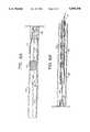
- FIGS. 1A and lBcomprise a plan view, partially in section, of a first embodiment of the invention assembled and ready for use prior to lead balloon inflation and sheath pressurization.
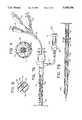
- FIGS. 2A and 2Bare slightly enlarged views of the proximal and distal ends, respectively, of the device shown. in FIGS. 1A and 1B with a guide wire in place and the lead balloon at the distal end of the guide sheath inflated;
- FIG. 3is a cross sectional view along the line 3--3 of FIG. 2B;
- FIG. 4is an enlarged side sectional view showing the manner in which the distal end of the deployment catheter is joined to the lead balloon catheter;
- FIGS. 5A and 5Bare slightly enlarged views showing the device with the deployment balloon positioned within the guide sheath and the lead balloon deflated and extended off and beyond the guide wire;
- FIGS. 6A and 6Bare slightly enlarged views showing the balloons after the deployment balloon has been inflated to expand the distal stent with the deflated lead balloon previously retracted into the sheath.
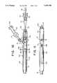
- FIGS. 7A and 7Bcomprise a plan view partially in section showing a second embodiment of the invention.
- FIG. 8is a sectional view along the line 8--8 of FIG. 7A;
- FIG. 9is a sectional view along the line 9--9 of FIG. 7B;
- FIG. 10is a plan view partially in section of a handle according to the invention.
- FIG. 11is a top view of the handle
- FIG. 12is a cross sectional view along the line 12--12 of FIG. 10;
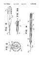
- FIG. 13is an enlarged view of a lead balloon and sheath
- FIG. 14is a plan view of a third embodiment in which the lead balloon is introduced into the distal end of the sheath and;
- FIG. 14Ais an enlarged side sectional view of the embodiment of FIG. 14 showing the manner in which the distal end of the deployment catheter is selectively joined to a lead balloon catheter.
- FIGS. 1-6illustrate an embodiment of the invention in which separate deployment and lead balloon catheters are used to deploy a graft stent complex shown as comprising a graft 12 and stent 14.
- Stent 14for example, may be a conventional Palmaz stent.
- the specific construction of the device to be deployedis not a feature of the invention.
- the delivery and deployment devicecomprises a guide sheath 20 which is adapted to be positioned within the patient's vasculature to facilitate delivery of the graft stent complex to the location where it is to be deployed.
- the guide sheath 20terminates at its proximal end in a three way hemostatic valve 21.
- Hemostatic valve 21may be a modified Tuoy Borst hemostatic valve having deployment catheter port 22, an end catheter port 24 and a sheath pressurization port 26 for purposes described below. Hemostatic valve 21 prevents the loss of blood through sheath 20 when its distal end is not sealed.
- Thumb screws 22A and 24Aclose ports 22 and 24, also locking in position the catheter which passes through the port.
- the sheath pressurization port 26is connected through a syringe 28 which may be of the type which includes an integral infusion pressure manometer 29 to provide the operator with a continuous indication of the pressure applied by the syringe to the port 26.
- the syringe 28may include a piston which is threadedly received within a bracket 31 fixed to the barrel. Pressure is applied by rotating a knob 28A at the end of the piston to advance the piston and apply very precise pressures to the sheath.
- Syringes of this typeare conventional disposable items.
- the syringemay be integrally formed with the port 28, or the port and syringe may be provided with standard connecting means so that the parts can be selectively coupled together.
- the guide sheath 20contains a deployment catheter 30 and a lead balloon catheter 40.
- the deployment catheter 30comprises an elongated flexible shaft 32 which includes a guide wire lumen 34 and an inflation lumen 36 (see FIG. 3).
- a deployment balloon 38is mounted on the distal end of the deployment catheter 30 in such a way that it can be inflated and deflated through the inflation lumen 36.
- the deployment balloon catheter 30terminates at its distal end in luer locks 38A and 38B which are connected by means of a standard bifurcated connector 39 to the proximal end of the catheter shaft 32.
- the luer lock 38Ais in fluid communication with the inflation lumen 36 and the luer lock 38B communicates with the guide wire lumen 34. Balloon catheters of this construction are conventional; therefore, the deployment catheter 30 is not described in further detail.
- the lead balloon catheter 40likewise is of conventional construction and includes an elongated flexible shaft 42 which includes a guide wire lumen 44 and an inflation lumen 46.
- a lead balloon 48is mounted at the distal end of the catheter 40 and can be selectively inflated and deflated through the inflation lumen 46.
- a luer lock 49is attached to the proximal end of the lead balloon catheter 40 so that the balloon 48 can be inflated by the introduction of fluid through the luer lock 49.
- the lead balloon shaft 42includes an opening 50 which, as most clearly shown in FIG. 4, is adapted to receive the distal end of the deployment catheter 30. Opening 50, which may be formed by skiving shaft 42, does not affect the inflation lumen 46 but enables the guide wire lumens 34 and 44 to be aligned in a substantially colinear relationship so that a standard guide wire 52 can be passed from the lead balloon catheter 40 to the guide wire lumen 34 of the deployment catheter 30 during use.
- sheath 20has a constant outer diameter, but the inner diameter of the proximal portion of the sheath (FIG. 1A) is less than the inner diameter of the distal portion (Fig. lB), i.e. the distal section is more flexible (less stiff) and includes a wider lumen.
- the proximal portion of the sheathprovides increased pushability and torquability of the catheter as it is inserted. Because the graft stent complex is muzzle loaded (as explained below), there is no need for a large internal diameter in the proximal segment of sheath 20 and a thicker wall is feasible.
- the wallis thin and indeed, may even be flimsy, for example, comparable to cellophane film. Reduction of wall thickness in the distal portion. of the sheath provides increased space in which the graft stent complex can be housed, which means that for a given outer diameter, a larger complex is possible with the invention. Pushability of the catheter is enhanced in part by the presence of the stent graft complex within the sheath but, primarily, the stiffness required is achieved by pressurizing the sheath by the introduction of fluid under pressure through port 26 of valve 21.
- the surgeoncan continuously vary the stiffness (and thus pushability and flexibility) of the sheath throughout the insertion procedure. This means that the surgeon has the capability of varying the stiffness of the catheter sheath during different phases of insertion depending on the degree of tortuously of the vascular system.
- the sheath 20may be made of PTFE (Teflon). The length and characteristics of the sheath will vary depending upon the particular application. Where an aortic aneurysm graft is to be deployed, the sheath 20 may be approximately 60 cm in length with the distalmost 15-20 cm comprising the flexible portion of the sheath. The sheath may be manufactured by standard extrusion techniques with the distal flexible portion thereafter cored from the extruded tube to form a thinner-walled flexible section.
- PTFETeflon
- the devicemay be assembled and sold in the condition shown in FIGS. 1A and lB, or it may be assembled at the time of use.
- the method of assemblyis as follows.
- Deployment catheter 30 and lead balloon catheter 40are passed through the deployment catheter port 22 and tip catheter port 24 of hemostatic valve 21 with the valve screws 22A and 22B open until the balloons 38 and 48 extend from the distal end of the sheath. If the device is to be used to deploy a graft stent complex 12, 14, the complex is then placed over the distal end of deployment catheter 30 with the balloon 38 beneath the stent 14. In conventional fashion, the stent 14 is crimped to balloon 38. The distal tip of deployment catheter 30 is then inserted into the opening 50 within the shaft 42 of lead balloon catheter 40 so that a continuous or colinear passageway is formed between the guide wire lumens 34 and 44.
- the graft stent complex and catheters 30 and 40are then muzzle loaded into the sheath 20 (i.e., retracted proximally into the sheath) and positioned so that, for example, about half of the lead balloon 48 extends from the distal end of the sheath 20, as shown in FIG. 2B.
- the lead balloon 48may be about four cm. in length which means that approximately two cm. of the balloon will extend distally from the sheath 20.
- the ability to muzzle load the catheters and graft-stent complex into the sheathis a valuable feature of the invention since it avoids the need to push the graft through the entire sheath which, in view of the length of the sheath, can be time consuming and may result in separation of the graft-stent complex (14,12) from the underlying balloon.
- a one-way valve 51(FIG. 2A) is attached to the lead balloon inflation port luer lock 49 and the lead balloon 48 inflated with saline solution from a standard ten cc. syringe 53 attached to luer lock 49.
- FIG. 2Bwhen the balloon 48 is inflated, it seals the distal end of the sheath 20 and provides a smooth taper which facilitates movement of the sheath through the patient's vasculature. Expansion of the balloon also results in a smooth transition between the sheath and balloon (see FIG.
- the lead balloonalso serves to aid in hemostasis, since blood cannot travel back through the sheath and out of the patient while the balloon is inflated.
- the syringe 28 attached to the sheath pressurization port 26is then used to inject saline into sheath 20 to a desired sheath pressure as measured by the infusion pressure manometer. After all air has been evacuated, i.e. the system has been bled, the catheter infusion ports are closed. The device is now ready to be inserted into the patient.
- the deviceis inserted as follows. First, the guide wire 52 is passed through the patient's vasculature with its location being confirmed fluoroscopically. In FIGS. 5A, 5B, 6A and 6B, a blood vessel is shown at 56 for purposes of explanation. The operator then inserts the proximal end of the guide wire into the distal end of the guide wire lumen 44 within lead balloon catheter 40. The operator next introduces sheath 20 into the patient over the guide wire. Because of the way in which the deployment catheter 30 is nested within the lead balloon catheter 40, the guide wire passes from the lead balloon guide wire lumen 44 into the colinear deployment guide wire lumen 34 as shown in FIG. 4.
- the operatorguides the sheath with the enclosed catheters to the location where the stent is to be deployed.
- the surgeoncan vary its flexibility to accommodate the specific vasculature by adjusting the pressure within the sheath as indicated by manometer 54.
- the sheath positionis determined fluoroscopically in a conventional fashion.
- the sheath 20may have regularly placed radiopaque markers so that the exact location of the sheath tip can be identified.
- lead balloon 48is deflated using the syringe.
- the thumbwheel 24A for the lead balloon catheter 40is then released and the lead balloon catheter advanced distally (with the position of the deployment catheter 30 held in place) until the catheter 40 is disengaged from the guide wire 52 (FIGS. 5A and 5B). This occurs when the opening 50 moves distally beyond the distal end of the guide wire 52.
- the thumb screw 22A which secures the deployment catheter 30is loosened and the sheath 20 retracted to expose the stent 14.
- the syringe with salineis attached to the luer lock 38B and the deployment balloon 38 is expanded to deploy the stent (FIGS. 6A and 6B).
- the deployment balloon 38is deflated. It may then be exchanged for a second deployment catheter containing a second stent to be properly positioned with respect to the graft 12 and deployed.
- graft 12may be provided with both stents, in which case the deployment catheter 30 can be withdrawn until the deployment balloon 38 is beneath the second stent. The balloon can then be expanded to deploy the second stent.
- the sheath 20 and catheters 30 and 40are then removed and a completion angiogram performed.
- the cathetercomprises an elongated flexible shaft 60 having a central guide wire lumen 62 and peripheral inflation lumens 64 and 66.
- a lead balloon 68is provided at the distal end of the catheter 60 for inflation through the lumen 64.
- a deployment balloon 70is positioned on the shaft 60 proximally of the lead balloon 68 and adapted to be inflated or deflated by means of the lumen 66.
- the lead balloon 68 and deployment balloon 70function the same way as the lead balloon 48 and deployment balloon 38 of the embodiment shown in FIGS. 1-6 but, of course, cannot be separated.
- the proximal end of the guide sheath 20terminates in a hemostatic valve 72 through which the catheter shaft 60 extends.
- the hemostatic valve 72includes a port 74 which may be connected to the syringe 28 shown in FIG. 1A.
- the port 74provides access to the interior of the sheath 20.
- a standard hemostatic valvemay be used as valve 72.
- the catheter shaft 60terminates in a conventional trifurcated firing 76 having three proximal ports which terminate in luer lock 78, 80, and 82.
- the luer locks 78 and 82provide access to the inflation lumens 64 and 66, respectively, while the luer lock 80 provides access to the guide wire lumen 62.
- the guide wire 52is inserted in conventional fashion through the guide wire lumen 62 of the catheter shaft 60.
- a one-way valvewould be connected to luer lock 78 to maintain the inflation of the lead balloon during use.
- hemostatic valve 21may be an ANGEDAPT Y-connector manufactured by Angeion Medical Products, Model No. AYC-020.
- Hemostatic valve 72may be of the type sold by Universal Medical Instrument Corp. under the trademark CATH-SEAL (Model No. 1200- 90-3003 ).
- the pressure syringe 28may be a LeVeen disposable inflation syringe with pressure gauge manufactured by the MedTech Division of Boston Scientific (Model No. 15-101).
- the guide sheathcomprises a relatively stiff flexible portion and a relatively flexible distal portion. It is conceivable that it may prove beneficial to have a continuously variable change in stiffness/flexibility, in which case the inner wall may taper gradually with the diameter increasing from the proximal end to the distal end. It is also possible that stiffness/flexibility may vary in a number of discrete steps, rather than in a single step as illustrated.
- the entire sheathcan be made of a highly flexible plastic (e.g., PTFE), which can be folded so as to reduce its cross section prior to insertion.
- PTFEa highly flexible plastic
- the advantage of this constructionis that a small introducer (and thus a smaller hole in the patient's artery) could be used to introduce the sheath into the patient's artery. Once in position, the sheath would be pressurized as described in the foregoing to increase its diameter as required for delivery and deployment of the stent.
- FIGS. 10-12illustrate a handle mechanism which, in use, reduces the likelihood of stent displacement when the physician retracts the sheath.
- FIGS. 10-12illustrate a handle construction for use with the two balloon embodiment shown in FIGS. 7-9 although the handle would have equal utility with the two catheter embodiment of FIGS. 1-6.
- the same numeralsare used to identify corresponding parts although some parts are illustrated as slightly different in appearance.
- the proximal end of the sheath 20is slidably retained within a handle 100 which includes an elongated slot 102 through which port 74 of the hemostatic valve 72 extends.
- the catheter shaft 60extends through a locking screw 104 attached to the proximal end of the handle 100 and through a locking screw 106 of the hemostatic valve 72 into the sheath 20.
- the hemostatic valveincludes a distal stop 108 adapted to abut against the distal edge 109 of slot 102 and a proximal stop 110 adapted to abut against the proximal edge 111 of slot 102.
- hemostatic valve 72In use, hemostatic valve 72 is pushed distally until the stop 108 abuts edge 109 of slot 102.
- the locking screw 106is loosened to permit movement of the valve 72 relative to the catheter shaft 60.
- Locking screw 104is tightened so that the handle 100 cannot move relative to the catheter shaft 60.
- the physicianholds the handle in one hand and pulls back on the port 74 until stop 110 abuts against the edge 111 of slot 102. Because the locking screw 104 retains the catheter 60 with respect to the handle 100, the sheath 20 is moved relative the catheter 60 the distance determined by the length of slot 102 and the positions of the stops 108 and 110. This permits the physician to hold the catheter 60 (and thus the stent) in a fixed location and withdraw the sheath by a precise amount. Therefore, the likelihood of human error causing improper positioning of the stent when the sheath is retracted is reduced.
- the inner surface of the distal end of sheath 20 and the outer surface of the lead balloon 48may be provided with mating circumferential ribs and grooves. These grooves may extend over about 1/2 inch and will prevent accidental expulsion of the lead balloon when sheath 20 is pressurized. Other comparable means may be used to retain the expanded lead balloon within the pressurized sheath 20.
- FIGS. 14shows an embodiment of the invention in which the lead balloon is mounted on a separate lead balloon catheter adapted to be introduced into the distal end of the sheath.
- the construction of FIG. 14is designed for use in a novel stent deployment procedure, described below, which is of special utility with patients having a tortuous vasculature through which it is difficult to move a stent deployment catheter.
- the catheter constructionis described.
- parts corresponding to the parts shown in the embodiment of FIGS. 7-9bear the same numbers.
- the catheter 60serves as a stent deployment catheter. It supports an inflatable balloon 70 on which stent 14 is mounted for deployment as explained above. Balloon 70 and stent 14 are retained within the sheath 20 which may be pressurized as described above.
- the lead balloon 68is on a separate lead balloon catheter 120.
- the adjoining ends of the lead balloon catheter 120 and the deployment catheter 60can be connected together in any suitable fashion which enables the catheters to be selectively connected and disconnected.
- the end of lead balloon catheter 120may be tapered and include a circumferential 122 detent adapted to engage a mating rim 124 on the deployment catheter 60 so that the two catheters are held securely together, as shown in detail in FIG. 14A.
- Numerous other connecting meanssuch as bayonet type connecters, threaded connectors, etc. can be used. The object is to make sure that the two catheters are securely held together during use but, as explained below, in such a way that they can be separated when it is necessary to withdraw them from the patient's vasculature.
- the catheter 60 and 120may be similar to the cross section shown in FIG. 8 with a central lumen through which a guidewire 52 passes. In each case, only a single inflation lumen 64 (or 66) is necessary.
- a small port 126may be provided in the catheter 120 for the purpose of introducing an angiographic contrast material as described in further detail below.
- a conventional one-way valve(not shown) should be provided in front of the port 126 (to the right of the port as illustrated in FIG. 14) so that the contrast material introduced into the central lumen will be blocked from flowing through the guide wire lumen and thus will exit through the port 126.
- the catheter construction of FIG. 14is designed to enable two physicians to simultaneously push and pull the deployed stent through the patient's vasculature. This is particularly beneficial in the case of patients with tortuous arteries as frequently encountered in the case of elderly patients. The way in which this is achieved is explained in the following.
- a needle puncture techniqueUsing a needle puncture technique a needle is inserted into the brachial artery in the patient's arm through a percutaneous approach. This needle is guided by palpating the pulse of the brachial artery and thereby advanced into the lumen of the artery. Through this needle, guidewire 52 is inserted and advanced into the lumen of the artery. Under fluoroscopic control, the guidewire is advanced retrograde (against the flow of blood) within the brachial artery to the axillary artery. From the axillary artery the wire moves directly into the left subclavian artery which connects directly with the thoracic portion of the aorta.
- the wireWhen the wire has entered the aorta in this retrograde fashion, it is advanced under fluoroscopic control down the thoracic aorta into the abdominal aorta. Once it has reached the distal end of the abdominal aorta it is selectively directed into either the right or left common iliac artery.
- the side into which the wire is directeddepends upon which artery has been chosen for subsequently advancing the sheath 20 and the stent deployment catheter 60. Generally, the larger of the two iliac arteries is chosen as the access vessel.
- the wire 52is then advanced under fluoroscopic control down through the common iliac artery into the external iliac artery and finally into the common femoral artery. Once the wire has reached the common femoral artery an incision is made into the common femoral artery. The wire is visualized and drawn out of this incision and left coiled outside the body. At this point one end of a very long wire is coiled outside of the femoral artery in the groin and the other end of this very long wire is coiled outside the body through a percutaneous puncture of the brachial artery in the left arm.
- the lead balloon catheter 120is advanced through the percutaneous puncture in the left brachial artery over the wire through all the vessels previously described down through the aorta and out the appropriate iliac artery, continuously following the guidewire 52.
- the stent deployment deviceis ready for use.
- the tip of lead balloon catheter 120is inserted into the distal end of deployment catheter so that the detent 122 and ridge 124 are locked together to form a fight union.
- the lead balloon catheter 120is advanced into the distal end of the sheath 20 so that approximately half of the balloon 168 is inside the sheath while the remaining half of the balloon is outside the sheath.
- the lead balloon 68is then inflated to maximum pressure thereby providing a smooth taper at the distal end of sheath 20.
- the distal end of the sheath 20 and lead balloonare carefully inserted into the previously created arteriotomy in the fernoral artery. This process is done by slowly pulling back slack on the lead balloon catheter 120 in the arm as the sheath 20 is advanced into the femoral artery and then retrograde into the external iliac artery.
- the sheath 20, at this juncture,is then pressurized to an appropriate pressure as previously described to produce an optimized balance of flexibility and pushability.
- pressurization of the sheath 20has been accomplished, by gently pulling on the lead balloon catheter 120 at its origin in the brachial artery while simultaneously pushing the sheath 20 from its distal end into the iliac artery, the entire system is advanced from the iliac arteries into the abdominal aorta and into a suitable position for deployment of the stent graft.
- the lead balloon 60is deflated.
- the sheath 20 covering the stent 14is then withdrawn to expose the stent and graft.
- an arteriogrammay be performed. This arteriogram is performed as follows.
- the guide wire 52which extends from the brachial artery to the common femoral artery is first removed.
- the one way valve in the tip of the lead balloon catheter 120permits only retrograde fluid flow in the catheter. Removing the guide wire 52 closes the valve mechanism permitting pressurization of the central lumen of the lead balloon catheter 120.
- Angiographic contrast materialis injected through the external port of lead balloon catheter 120 into the guide wire lumen of the catheter and exits from port 126 in the catheter shaft. Contrast cannot continue down the balloon catheter shaft because the closed valve occludes the passage way. This angiogram injection will permit final localization of the appropriate position for the stent graft.
- the guide wire 52is then reinserted through the groin and out through the brachial artery.
- sheath 20is retracted and the deployment balloon 70 inflated to deploy the stent 14.
- tensionis maintained on the lead balloon catheter shaft 120 (with lead balloon 68 deflated).
- the catheters 120 and 60are disconnected either by applying gentle opposite tension to both balloon catheter shafts or by advancing the tips of both catheters out of the common femoral artery where they can be disengaged manually. Additional procedures including the placement of additional stents could then be performed using well described standard techniques.
- the stent deployment meansmay comprise a mechanical device rather than a balloon.
- One suitable device for mechanically deploying a stentis shown in copending U.S. patent application Ser. No. 08/196,278, filed Feb. 10, 1994, in the names of Michael and Ralph Marin, and entitled APPARATUS AND METHOD FOR DEPLOYMENT OF RADIALLY EXPANDABLE STENTS BY A MECHANICAL LINKAGE. Now U.S.Pat. No. 5,443,477.
- the broad principles of the inventioncan be used in the delivery and/or deployment of other intraluminal devices such as but not limited to VenaCava filters, atherectomy devices and the like.
- a balloon cathetermay be introduced into the thoracic aorta and the balloon expanded to permit the blood flow to push the catheter distally to a desired location such as the common femoral artery.
- the right or left arterycan be selected by applying pressure to one artery causing the balloon to move to the other.
- the cathetercan then be pulled from the artery and used as explained above or in any desired way to simultaneously push and pull an intraluminal device through the patient's arteries.
Landscapes
- Health & Medical Sciences (AREA)
- Life Sciences & Earth Sciences (AREA)
- Engineering & Computer Science (AREA)
- Biomedical Technology (AREA)
- Heart & Thoracic Surgery (AREA)
- Animal Behavior & Ethology (AREA)
- Veterinary Medicine (AREA)
- Public Health (AREA)
- General Health & Medical Sciences (AREA)
- Pulmonology (AREA)
- Vascular Medicine (AREA)
- Transplantation (AREA)
- Oral & Maxillofacial Surgery (AREA)
- Biophysics (AREA)
- Cardiology (AREA)
- Anesthesiology (AREA)
- Hematology (AREA)
- Gastroenterology & Hepatology (AREA)
- Child & Adolescent Psychology (AREA)
- Media Introduction/Drainage Providing Device (AREA)
- Vehicle Body Suspensions (AREA)
- Electrotherapy Devices (AREA)
- Adornments (AREA)
- Prostheses (AREA)
- Farming Of Fish And Shellfish (AREA)
- Pinball Game Machines (AREA)
- Manipulator (AREA)
- Ultra Sonic Daignosis Equipment (AREA)
Abstract
Description
Claims (4)
Priority Applications (3)
| Application Number | Priority Date | Filing Date | Title |
|---|---|---|---|
| US08/483,191US5569296A (en) | 1994-05-13 | 1995-06-07 | Method for delivering and deploying intraluminal devices |
| AU61784/96AAU6178496A (en) | 1995-06-07 | 1996-06-07 | Device and method for delivering and deploying intraluminal devices |
| PCT/US1996/010405WO1996039997A2 (en) | 1995-06-07 | 1996-06-07 | Device and method for delivering and deploying intraluminal devices |
Applications Claiming Priority (2)
| Application Number | Priority Date | Filing Date | Title |
|---|---|---|---|
| US08/243,190US5456694A (en) | 1994-05-13 | 1994-05-13 | Device for delivering and deploying intraluminal devices |
| US08/483,191US5569296A (en) | 1994-05-13 | 1995-06-07 | Method for delivering and deploying intraluminal devices |
Related Parent Applications (1)
| Application Number | Title | Priority Date | Filing Date |
|---|---|---|---|
| US08/243,190Continuation-In-PartUS5456694A (en) | 1994-05-13 | 1994-05-13 | Device for delivering and deploying intraluminal devices |
Publications (1)
| Publication Number | Publication Date |
|---|---|
| US5569296Atrue US5569296A (en) | 1996-10-29 |
Family
ID=22917696
Family Applications (3)
| Application Number | Title | Priority Date | Filing Date |
|---|---|---|---|
| US08/243,190Expired - LifetimeUS5456694A (en) | 1994-05-13 | 1994-05-13 | Device for delivering and deploying intraluminal devices |
| US08/483,190Expired - LifetimeUS5697948A (en) | 1994-05-13 | 1995-06-07 | Device for delivering and deploying intraluminal devices |
| US08/483,191Expired - LifetimeUS5569296A (en) | 1994-05-13 | 1995-06-07 | Method for delivering and deploying intraluminal devices |
Family Applications Before (2)
| Application Number | Title | Priority Date | Filing Date |
|---|---|---|---|
| US08/243,190Expired - LifetimeUS5456694A (en) | 1994-05-13 | 1994-05-13 | Device for delivering and deploying intraluminal devices |
| US08/483,190Expired - LifetimeUS5697948A (en) | 1994-05-13 | 1995-06-07 | Device for delivering and deploying intraluminal devices |
Country Status (12)
| Country | Link |
|---|---|
| US (3) | US5456694A (en) |
| EP (1) | EP0758871B1 (en) |
| JP (1) | JP3716862B2 (en) |
| KR (1) | KR970702701A (en) |
| AT (1) | ATE272989T1 (en) |
| AU (1) | AU2597195A (en) |
| CA (1) | CA2189794A1 (en) |
| DE (1) | DE69533356T2 (en) |
| DK (1) | DK0758871T3 (en) |
| ES (1) | ES2224127T3 (en) |
| PT (1) | PT758871E (en) |
| WO (1) | WO1995031155A1 (en) |
Cited By (57)
| Publication number | Priority date | Publication date | Assignee | Title |
|---|---|---|---|---|
| US5728104A (en)* | 1996-03-12 | 1998-03-17 | Cordis Corporation | Method of catheter balloon manufacture and use |
| US5788708A (en)* | 1996-09-20 | 1998-08-04 | Intella Interventional Systems, Inc. | Multiple balloon stent delivery catheter and method |
| US5827301A (en)* | 1996-02-29 | 1998-10-27 | Willy Rusch Ag | Device and method for intraoperative calibration of a fundus fold cuff |
| US5931842A (en)* | 1996-11-07 | 1999-08-03 | Vascular Science Inc. | Methods and apparatus for handling tubing used in medical procedures |
| US5968068A (en)* | 1996-09-12 | 1999-10-19 | Baxter International Inc. | Endovascular delivery system |
| US6129756A (en)* | 1998-03-16 | 2000-10-10 | Teramed, Inc. | Biluminal endovascular graft system |
| US6136007A (en)* | 1997-04-17 | 2000-10-24 | St. Jude Medical Cardiovascular Group, Inc, | Apparatus for handling tubing used in medical procedures |
| US6139572A (en)* | 1995-09-18 | 2000-10-31 | W. L. Gore & Associates, Inc. | Delivery system for intraluminal vascular grafts |
| US6143016A (en)* | 1997-04-21 | 2000-11-07 | Advanced Cardiovascular Systems, Inc. | Sheath and method of use for a stent delivery system |
| US6224609B1 (en) | 1998-03-16 | 2001-05-01 | Teramed Inc. | Bifurcated prosthetic graft |
| US6275724B1 (en)* | 1998-03-27 | 2001-08-14 | Intravascular Research Limited | Medical ultrasonic imaging |
| US6273909B1 (en) | 1998-10-05 | 2001-08-14 | Teramed Inc. | Endovascular graft system |
| US6451025B1 (en) | 1996-04-01 | 2002-09-17 | General Surgical Innovations, Inc. | Prosthesis and method for deployment within a body lumen |
| US20020173785A1 (en)* | 2000-03-31 | 2002-11-21 | Medtronic, Inc. | System and method for positioning implantable medical devices within coronary veins |
| US20020193821A1 (en)* | 2001-06-19 | 2002-12-19 | Trout Hugh H. | Positioning assembly and method of use |
| US6567704B2 (en)* | 2000-12-20 | 2003-05-20 | Medtronic, Inc. | Medical electrical lead and method of use |
| US6592569B2 (en) | 1999-11-09 | 2003-07-15 | Advanced Cardiovascular Systems, Inc. | Protective sheath for catheters |
| US6733500B2 (en) | 2000-03-31 | 2004-05-11 | Medtronic, Inc. | Method and system for delivering a medical electrical lead within a venous system |
| US20040098085A1 (en)* | 2000-02-11 | 2004-05-20 | Ricci Donald R. | Stent delivery system and method of use |
| US6743219B1 (en) | 2000-08-02 | 2004-06-01 | Cordis Corporation | Delivery apparatus for a self-expanding stent |
| US20040243007A1 (en)* | 2001-01-12 | 2004-12-02 | Radi Medical Systems Ab | Technique to confirm correct positioning with respect to arterial wall |
| US6849077B2 (en) | 2000-02-11 | 2005-02-01 | Evysio Medical Devices Ulc | Stent delivery system and method of use |
| US20050033416A1 (en)* | 2003-05-02 | 2005-02-10 | Jacques Seguin | Vascular graft and deployment system |
| US20050154441A1 (en)* | 2004-01-14 | 2005-07-14 | Cook Incorporated | Introducer |
| US20060079859A1 (en)* | 2002-09-20 | 2006-04-13 | Flowmedica, Inc. | Renal infusion systems and methods |
| US20060161244A1 (en)* | 2003-05-02 | 2006-07-20 | Jacques Seguin | Vascular graft and deployment system |
| US20060259123A1 (en)* | 2003-09-25 | 2006-11-16 | C. R. Bard, Inc. | Lining for bodily lumen |
| US20070005122A1 (en)* | 2004-09-24 | 2007-01-04 | Olympus Corporation | Treatment instrument installation member, stent delivery catheter and conduit system |
| US7169170B2 (en) | 2002-02-22 | 2007-01-30 | Cordis Corporation | Self-expanding stent delivery system |
| US20070083256A1 (en)* | 2003-04-28 | 2007-04-12 | C.R. Bard, Inc. | Loading and delivery of self-expanding stents |
| US20070185524A1 (en)* | 2006-02-03 | 2007-08-09 | Pedro Diaz | Rapid exchange emboli capture guidewire system and methods of use |
| US20070288036A1 (en)* | 2006-06-09 | 2007-12-13 | Niranjan Seshadri | Assembly for crossing a chronic total occlusion and method therefor |
| US20080009770A1 (en)* | 2005-02-28 | 2008-01-10 | Jan Weber | Stent delivery and guidewire guidance system |
| US20090005760A1 (en)* | 2006-07-31 | 2009-01-01 | Richard George Cartledge | Sealable endovascular implants and methods for their use |
| US7585836B2 (en) | 2004-05-14 | 2009-09-08 | Goodson Iv Harry Burt | Bi-lateral local renal delivery for treating congestive heart failure and for BNP therapy |
| US20100070016A1 (en)* | 2008-09-16 | 2010-03-18 | C. R. Bard, Inc. | Stent device adhesively bonded to a stent device pusher |
| US7766961B2 (en) | 2003-06-05 | 2010-08-03 | Angio Dynamics, Inc. | Systems and methods for performing bi-lateral interventions or diagnosis in branched body lumens |
| US7771401B2 (en) | 2006-06-08 | 2010-08-10 | Angiodynamics, Inc. | Selective renal cannulation and infusion systems and methods |
| US7914503B2 (en) | 2002-09-20 | 2011-03-29 | Angio Dynamics | Method and apparatus for selective material delivery via an intra-renal catheter |
| US7935141B2 (en) | 2005-08-17 | 2011-05-03 | C. R. Bard, Inc. | Variable speed stent delivery system |
| US20110251555A1 (en)* | 2009-10-19 | 2011-10-13 | Wilson-Cook Medical Inc. | Balloon-tipped endoscopic system with inverted sleeve |
| US8062344B2 (en) | 2001-04-30 | 2011-11-22 | Angiomed Gmbh & Co. Medizintechnik Kg | Variable speed self-expanding stent delivery system and luer locking connector |
| US8500789B2 (en) | 2007-07-11 | 2013-08-06 | C. R. Bard, Inc. | Device for catheter sheath retraction |
| US8518011B2 (en) | 2004-03-04 | 2013-08-27 | Angiodynamics, Inc. | Sheath for use in peripheral interventions |
| US8585678B2 (en) | 2002-09-20 | 2013-11-19 | Angiodynamics, Inc. | Method and apparatus for intra-aortic substance delivery to a branch vessel |
| US8679172B2 (en) | 2009-01-29 | 2014-03-25 | C. R. Bard, Inc. | Delivery device for delivering a stent device |
| US8808346B2 (en) | 2006-01-13 | 2014-08-19 | C. R. Bard, Inc. | Stent delivery system |
| US8920484B2 (en) | 2009-05-29 | 2014-12-30 | C. R. Bard, Inc. | Transluminal delivery system |
| US9078779B2 (en) | 2006-08-07 | 2015-07-14 | C. R. Bard, Inc. | Hand-held actuator device |
| US9408607B2 (en) | 2009-07-02 | 2016-08-09 | Edwards Lifesciences Cardiaq Llc | Surgical implant devices and methods for their manufacture and use |
| US9566178B2 (en) | 2010-06-24 | 2017-02-14 | Edwards Lifesciences Cardiaq Llc | Actively controllable stent, stent graft, heart valve and method of controlling same |
| US9585743B2 (en) | 2006-07-31 | 2017-03-07 | Edwards Lifesciences Cardiaq Llc | Surgical implant devices and methods for their manufacture and use |
| US9801745B2 (en) | 2010-10-21 | 2017-10-31 | C.R. Bard, Inc. | System to deliver a bodily implant |
| US9814611B2 (en) | 2007-07-31 | 2017-11-14 | Edwards Lifesciences Cardiaq Llc | Actively controllable stent, stent graft, heart valve and method of controlling same |
| US9827093B2 (en) | 2011-10-21 | 2017-11-28 | Edwards Lifesciences Cardiaq Llc | Actively controllable stent, stent graft, heart valve and method of controlling same |
| US10905853B2 (en) | 2017-01-17 | 2021-02-02 | DePuy Synthes Products, Inc. | System and method for delivering a catheter |
| US11026822B2 (en) | 2006-01-13 | 2021-06-08 | C. R. Bard, Inc. | Stent delivery system |
Families Citing this family (264)
| Publication number | Priority date | Publication date | Assignee | Title |
|---|---|---|---|---|
| CA2060067A1 (en)* | 1991-01-28 | 1992-07-29 | Lilip Lau | Stent delivery system |
| US6029671A (en)* | 1991-07-16 | 2000-02-29 | Heartport, Inc. | System and methods for performing endovascular procedures |
| CA2079417C (en) | 1991-10-28 | 2003-01-07 | Lilip Lau | Expandable stents and method of making same |
| US6770066B1 (en) | 1992-05-11 | 2004-08-03 | Ballard Medical Products | Multi-lumen endoscopic catheter |
| US5498227A (en) | 1993-09-15 | 1996-03-12 | Mawad; Michel E. | Retrievable, shielded radiotherapy implant |
| US5507769A (en) | 1994-10-18 | 1996-04-16 | Stentco, Inc. | Method and apparatus for forming an endoluminal bifurcated graft |
| US6039749A (en) | 1994-02-10 | 2000-03-21 | Endovascular Systems, Inc. | Method and apparatus for deploying non-circular stents and graftstent complexes |
| US5662675A (en)* | 1995-02-24 | 1997-09-02 | Intervascular, Inc. | Delivery catheter assembly |
| US6235021B1 (en)* | 1995-05-01 | 2001-05-22 | Scimed Life Systems, Inc. | Ablation sheath |
| US5662614A (en)* | 1995-05-09 | 1997-09-02 | Edoga; John K. | Balloon expandable universal access sheath |
| US5639274A (en)* | 1995-06-02 | 1997-06-17 | Fischell; Robert E. | Integrated catheter system for balloon angioplasty and stent delivery |
| AU6178496A (en)* | 1995-06-07 | 1996-12-30 | Stentco, Inc. | Device and method for delivering and deploying intraluminal devices |
| ATE440559T1 (en)* | 1995-10-13 | 2009-09-15 | Medtronic Vascular Inc | DEVICE FOR INTERSTITIAL TRANSVASCULAR PROCEDURES |
| US6302875B1 (en)* | 1996-10-11 | 2001-10-16 | Transvascular, Inc. | Catheters and related devices for forming passageways between blood vessels or other anatomical structures |
| US6375615B1 (en) | 1995-10-13 | 2002-04-23 | Transvascular, Inc. | Tissue penetrating catheters having integral imaging transducers and their methods of use |
| DE69633411T2 (en) | 1995-10-13 | 2005-10-20 | Transvascular, Inc., Menlo Park | METHOD AND DEVICE FOR PREVENTING ARTERIAL ATTRACTIONS AND / OR FOR CARRYING OUT OTHER TRANSVASCULAR INTERVENTIONS |
| US5749848A (en)* | 1995-11-13 | 1998-05-12 | Cardiovascular Imaging Systems, Inc. | Catheter system having imaging, balloon angioplasty, and stent deployment capabilities, and method of use for guided stent deployment |
| US5746764A (en)* | 1995-12-04 | 1998-05-05 | Atrion Medical Products, Inc. | Stent compression instrument |
| US5690642A (en) | 1996-01-18 | 1997-11-25 | Cook Incorporated | Rapid exchange stent delivery balloon catheter |
| AUPN775296A0 (en)† | 1996-01-25 | 1996-02-22 | Endogad Research Pty Limited | Directional catheter |
| US6709444B1 (en)* | 1996-02-02 | 2004-03-23 | Transvascular, Inc. | Methods for bypassing total or near-total obstructions in arteries or other anatomical conduits |
| US5947978A (en) | 1996-04-15 | 1999-09-07 | Medical Innovations Corp. | Surgical combination apparatus having first and second instruments operated from a common actuator |
| US5709701A (en)* | 1996-05-30 | 1998-01-20 | Parodi; Juan C. | Apparatus for implanting a prothesis within a body passageway |
| US6077295A (en)* | 1996-07-15 | 2000-06-20 | Advanced Cardiovascular Systems, Inc. | Self-expanding stent delivery system |
| US6432127B1 (en) | 1996-10-11 | 2002-08-13 | Transvascular, Inc. | Devices for forming and/or maintaining connections between adjacent anatomical conduits |
| US6599316B2 (en) | 1996-11-04 | 2003-07-29 | Advanced Stent Technologies, Inc. | Extendible stent apparatus |
| US6692483B2 (en) | 1996-11-04 | 2004-02-17 | Advanced Stent Technologies, Inc. | Catheter with attached flexible side sheath |
| US6835203B1 (en) | 1996-11-04 | 2004-12-28 | Advanced Stent Technologies, Inc. | Extendible stent apparatus |
| US7591846B2 (en) | 1996-11-04 | 2009-09-22 | Boston Scientific Scimed, Inc. | Methods for deploying stents in bifurcations |
| US8211167B2 (en) | 1999-12-06 | 2012-07-03 | Boston Scientific Scimed, Inc. | Method of using a catheter with attached flexible side sheath |
| US7341598B2 (en) | 1999-01-13 | 2008-03-11 | Boston Scientific Scimed, Inc. | Stent with protruding branch portion for bifurcated vessels |
| US7220275B2 (en) | 1996-11-04 | 2007-05-22 | Advanced Stent Technologies, Inc. | Stent with protruding branch portion for bifurcated vessels |
| US6325826B1 (en) | 1998-01-14 | 2001-12-04 | Advanced Stent Technologies, Inc. | Extendible stent apparatus |
| EP1723931B1 (en) | 1996-11-04 | 2012-01-04 | Advanced Stent Technologies, Inc. | Extendible stent apparatus and method for deploying the same |
| US5972017A (en) | 1997-04-23 | 1999-10-26 | Vascular Science Inc. | Method of installing tubular medical graft connectors |
| US5749890A (en)* | 1996-12-03 | 1998-05-12 | Shaknovich; Alexander | Method and system for stent placement in ostial lesions |
| US6071286A (en)* | 1997-02-19 | 2000-06-06 | Mawad; Michel E. | Combination angioplasty balloon/stent deployment device |
| US6090128A (en)* | 1997-02-20 | 2000-07-18 | Endologix, Inc. | Bifurcated vascular graft deployment device |
| US6951572B1 (en) | 1997-02-20 | 2005-10-04 | Endologix, Inc. | Bifurcated vascular graft and method and apparatus for deploying same |
| US5851210A (en)* | 1997-03-21 | 1998-12-22 | Torossian; Richard | Stent delivery system and method |
| GB9706766D0 (en)* | 1997-04-03 | 1997-05-21 | Sulzer Vascutek Ltd | Endovascular prostheses |
| US6070589A (en) | 1997-08-01 | 2000-06-06 | Teramed, Inc. | Methods for deploying bypass graft stents |
| US6165195A (en) | 1997-08-13 | 2000-12-26 | Advanced Cardiovascylar Systems, Inc. | Stent and catheter assembly and method for treating bifurcations |
| US7753950B2 (en) | 1997-08-13 | 2010-07-13 | Advanced Cardiovascular Systems, Inc. | Stent and catheter assembly and method for treating bifurcations |
| US5948017A (en)* | 1997-10-12 | 1999-09-07 | Taheri; Syde A. | Modular graft assembly |
| US6013085A (en)* | 1997-11-07 | 2000-01-11 | Howard; John | Method for treating stenosis of the carotid artery |
| US6217527B1 (en) | 1998-09-30 | 2001-04-17 | Lumend, Inc. | Methods and apparatus for crossing vascular occlusions |
| US20050171478A1 (en)* | 1998-01-13 | 2005-08-04 | Selmon Matthew R. | Catheter system for crossing total occlusions in vasculature |
| US6231546B1 (en) | 1998-01-13 | 2001-05-15 | Lumend, Inc. | Methods and apparatus for crossing total occlusions in blood vessels |
| US6174327B1 (en) | 1998-02-27 | 2001-01-16 | Scimed Life Systems, Inc. | Stent deployment apparatus and method |
| US6077296A (en) | 1998-03-04 | 2000-06-20 | Endologix, Inc. | Endoluminal vascular prosthesis |
| US6290731B1 (en) | 1998-03-30 | 2001-09-18 | Cordis Corporation | Aortic graft having a precursor gasket for repairing an abdominal aortic aneurysm |
| US6887268B2 (en) | 1998-03-30 | 2005-05-03 | Cordis Corporation | Extension prosthesis for an arterial repair |
| US6626938B1 (en) | 2000-11-16 | 2003-09-30 | Cordis Corporation | Stent graft having a pleated graft member |
| US6136011A (en)* | 1998-07-14 | 2000-10-24 | Advanced Cardiovascular Systems, Inc. | Stent delivery system and method of use |
| US6325824B2 (en) | 1998-07-22 | 2001-12-04 | Advanced Cardiovascular Systems, Inc. | Crush resistant stent |
| NL1009738C2 (en)* | 1998-07-24 | 2000-01-25 | Cordis Europ | Balloon catheter with filler for stent delivery. |
| US5944727A (en)* | 1998-09-02 | 1999-08-31 | Datascope Investment Corp. | Stent/graft catheter handle |
| US6196230B1 (en) | 1998-09-10 | 2001-03-06 | Percardia, Inc. | Stent delivery system and method of use |
| JP2002524196A (en) | 1998-09-10 | 2002-08-06 | パーカーディア,インコーポレイティド | Transmyocardial shunt for left ventricular revascularization and its mounting mechanism |
| US6261304B1 (en) | 1998-09-10 | 2001-07-17 | Percardia, Inc. | Delivery methods for left ventricular conduit |
| AU6384699A (en) | 1998-09-10 | 2000-04-03 | Percardia, Inc. | Tmr shunt |
| EP1447057A1 (en) | 1998-09-30 | 2004-08-18 | Bard Peripheral Vascular, Inc. | Delivery mechanism for implantable stent |
| US6733523B2 (en) | 1998-12-11 | 2004-05-11 | Endologix, Inc. | Implantable vascular graft |
| US6187036B1 (en) | 1998-12-11 | 2001-02-13 | Endologix, Inc. | Endoluminal vascular prosthesis |
| US6660030B2 (en) | 1998-12-11 | 2003-12-09 | Endologix, Inc. | Bifurcation graft deployment catheter |
| WO2000033769A1 (en) | 1998-12-11 | 2000-06-15 | Endologix, Inc. | Endoluminal vascular prosthesis |
| US6383204B1 (en) | 1998-12-15 | 2002-05-07 | Micrus Corporation | Variable stiffness coil for vasoocclusive devices |
| US6071287A (en)* | 1998-12-23 | 2000-06-06 | Medtronic, Inc. | Introducer for single operator stent delivery system |
| US7655030B2 (en) | 2003-07-18 | 2010-02-02 | Boston Scientific Scimed, Inc. | Catheter balloon systems and methods |
| US6261316B1 (en) | 1999-03-11 | 2001-07-17 | Endologix, Inc. | Single puncture bifurcation graft deployment system |
| US8034100B2 (en) | 1999-03-11 | 2011-10-11 | Endologix, Inc. | Graft deployment system |
| US6190360B1 (en) | 1999-04-09 | 2001-02-20 | Endotex Interventional System | Stent delivery handle |
| US6375676B1 (en) | 1999-05-17 | 2002-04-23 | Advanced Cardiovascular Systems, Inc. | Self-expanding stent with enhanced delivery precision and stent delivery system |
| US6884258B2 (en) | 1999-06-04 | 2005-04-26 | Advanced Stent Technologies, Inc. | Bifurcation lesion stent delivery using multiple guidewires |
| US6231496B1 (en)* | 1999-07-07 | 2001-05-15 | Peter J. Wilk | Medical treatment method |
| US6638237B1 (en) | 1999-08-04 | 2003-10-28 | Percardia, Inc. | Left ventricular conduits and methods for delivery |
| US6302892B1 (en) | 1999-08-04 | 2001-10-16 | Percardia, Inc. | Blood flow conduit delivery system and method of use |
| US6183493B1 (en) | 1999-08-24 | 2001-02-06 | Pharmasys International, Llc | Method and apparatus for the treatment of sleep apnea and related breathing disorders |
| US7022100B1 (en) | 1999-09-03 | 2006-04-04 | A-Med Systems, Inc. | Guidable intravascular blood pump and related methods |
| US6559934B1 (en)* | 1999-09-14 | 2003-05-06 | Visx, Incorporated | Method and apparatus for determining characteristics of a laser beam spot |
| US6689156B1 (en) | 1999-09-23 | 2004-02-10 | Advanced Stent Technologies, Inc. | Stent range transducers and methods of use |
| US6383171B1 (en)* | 1999-10-12 | 2002-05-07 | Allan Will | Methods and devices for protecting a passageway in a body when advancing devices through the passageway |
| US6443979B1 (en) | 1999-12-20 | 2002-09-03 | Advanced Cardiovascular Systems, Inc. | Expandable stent delivery sheath and method of use |
| US6602280B2 (en) | 2000-02-02 | 2003-08-05 | Trivascular, Inc. | Delivery system and method for expandable intracorporeal device |
| US6702843B1 (en) | 2000-04-12 | 2004-03-09 | Scimed Life Systems, Inc. | Stent delivery means with balloon retraction means |
| US6854467B2 (en) | 2000-05-04 | 2005-02-15 | Percardia, Inc. | Methods and devices for delivering a ventricular stent |
| WO2001087399A2 (en) | 2000-05-18 | 2001-11-22 | Wilson-Cook Medical Inc. | Medical device with improved wire guide access |
| US6527779B1 (en) | 2000-07-10 | 2003-03-04 | Endotex Interventional Systems, Inc. | Stent delivery device |
| US6649030B1 (en) | 2000-08-31 | 2003-11-18 | Endovascular Technologies, Inc. | Physical vapor deposition of radiopaque markings on a graft |
| US6945989B1 (en) | 2000-09-18 | 2005-09-20 | Endotex Interventional Systems, Inc. | Apparatus for delivering endoluminal prostheses and methods of making and using them |
| US20020193863A1 (en)* | 2000-09-18 | 2002-12-19 | Endotex Interventional Systems, Inc. | Apparatus for delivering endoluminal prosthesis and methods for preparing such apparatus for delivery |
| US6690970B1 (en) | 2000-10-06 | 2004-02-10 | Syde A. Taheri | Biological pacemaker and implantation catheter |
| US6602226B1 (en) | 2000-10-12 | 2003-08-05 | Scimed Life Systems, Inc. | Low-profile stent delivery system and apparatus |
| US7314483B2 (en) | 2000-11-16 | 2008-01-01 | Cordis Corp. | Stent graft with branch leg |
| US6942692B2 (en) | 2000-11-16 | 2005-09-13 | Cordis Corporation | Supra-renal prosthesis and renal artery bypass |
| US7229472B2 (en) | 2000-11-16 | 2007-06-12 | Cordis Corporation | Thoracic aneurysm repair prosthesis and system |
| US6843802B1 (en) | 2000-11-16 | 2005-01-18 | Cordis Corporation | Delivery apparatus for a self expanding retractable stent |
| US7267685B2 (en) | 2000-11-16 | 2007-09-11 | Cordis Corporation | Bilateral extension prosthesis and method of delivery |
| AU2002235159A1 (en)* | 2000-12-05 | 2002-06-18 | Lumend, Inc. | Catheter system for vascular re-entry from a sub-intimal space |
| EP1258230A3 (en) | 2001-03-29 | 2003-12-10 | CardioSafe Ltd | Balloon catheter device |
| US6733521B2 (en) | 2001-04-11 | 2004-05-11 | Trivascular, Inc. | Delivery system and method for endovascular graft |
| US6761733B2 (en) | 2001-04-11 | 2004-07-13 | Trivascular, Inc. | Delivery system and method for bifurcated endovascular graft |
| US8617231B2 (en) | 2001-05-18 | 2013-12-31 | Boston Scientific Scimed, Inc. | Dual guidewire exchange catheter system |
| US20040034383A1 (en)* | 2001-07-31 | 2004-02-19 | Amir Belson | Flow-directed catheter guide with variable rigidity shaft |
| GB0121980D0 (en) | 2001-09-11 | 2001-10-31 | Cathnet Science Holding As | Expandable stent |
| CA2462509A1 (en) | 2001-10-04 | 2003-04-10 | Neovasc Medical Ltd. | Flow reducing implant |
| EP1441666B1 (en) | 2001-11-09 | 2008-01-23 | Rubicon Medical, Inc. | Stent delivery device with embolic protection |
| US7594926B2 (en) | 2001-11-09 | 2009-09-29 | Boston Scientific Scimed, Inc. | Methods, systems and devices for delivering stents |
| US20030135266A1 (en) | 2001-12-03 | 2003-07-17 | Xtent, Inc. | Apparatus and methods for delivery of multiple distributed stents |
| US8080048B2 (en) | 2001-12-03 | 2011-12-20 | Xtent, Inc. | Stent delivery for bifurcated vessels |
| US7270668B2 (en) | 2001-12-03 | 2007-09-18 | Xtent, Inc. | Apparatus and methods for delivering coiled prostheses |
| US7892273B2 (en) | 2001-12-03 | 2011-02-22 | Xtent, Inc. | Custom length stent apparatus |
| US7351255B2 (en) | 2001-12-03 | 2008-04-01 | Xtent, Inc. | Stent delivery apparatus and method |
| US7137993B2 (en) | 2001-12-03 | 2006-11-21 | Xtent, Inc. | Apparatus and methods for delivery of multiple distributed stents |
| US20040186551A1 (en) | 2003-01-17 | 2004-09-23 | Xtent, Inc. | Multiple independent nested stent structures and methods for their preparation and deployment |
| US7182779B2 (en)* | 2001-12-03 | 2007-02-27 | Xtent, Inc. | Apparatus and methods for positioning prostheses for deployment from a catheter |
| US7309350B2 (en) | 2001-12-03 | 2007-12-18 | Xtent, Inc. | Apparatus and methods for deployment of vascular prostheses |
| US7147656B2 (en) | 2001-12-03 | 2006-12-12 | Xtent, Inc. | Apparatus and methods for delivery of braided prostheses |
| US7294146B2 (en) | 2001-12-03 | 2007-11-13 | Xtent, Inc. | Apparatus and methods for delivery of variable length stents |
| US20100016943A1 (en) | 2001-12-20 | 2010-01-21 | Trivascular2, Inc. | Method of delivering advanced endovascular graft |
| US7326237B2 (en) | 2002-01-08 | 2008-02-05 | Cordis Corporation | Supra-renal anchoring prosthesis |
| US7235095B2 (en)* | 2002-02-22 | 2007-06-26 | Scimed Life Systems, Inc. | Method and system for deploying multi-part endoluminal devices |
| US7004964B2 (en)* | 2002-02-22 | 2006-02-28 | Scimed Life Systems, Inc. | Apparatus and method for deployment of an endoluminal device |
| US7887573B2 (en)* | 2002-02-22 | 2011-02-15 | Boston Scientific Scimed, Inc. | Method and apparatus for deployment of an endoluminal device |
| ITMO20020152A1 (en)* | 2002-06-05 | 2003-12-05 | Mariangela Moggi | LARGE VASES CLAMPING DEVICE |
| US20060135340A1 (en)* | 2002-07-30 | 2006-06-22 | Cheang Hong N P | Spherical nano-composite powder and a method of preparing the same |
| US20050256092A1 (en)* | 2002-08-01 | 2005-11-17 | Shin Shimaoka | Antipsoriatic agent |
| ITRM20020596A1 (en)* | 2002-11-27 | 2004-05-28 | Mauro Ferrari | IMPLANT VASCULAR PROSTHESIS WITH COMBINED, LAPAROSCOPIC AND ENDOVASCULAR TECHNIQUES, FOR THE TREATMENT OF ABDOMINAL AORTIC ANEURYSMS, AND OPERATIONAL EQUIPMENT FOR THE RELEASE OF A PROSTHESIS EQUIPPED WITH ANCHORING STENTS. |
| US6899729B1 (en) | 2002-12-18 | 2005-05-31 | Advanced Cardiovascular Systems, Inc. | Stent for treating vulnerable plaque |
| US6896697B1 (en) | 2002-12-30 | 2005-05-24 | Advanced Cardiovascular Systems, Inc. | Intravascular stent |
| US7316710B1 (en) | 2002-12-30 | 2008-01-08 | Advanced Cardiovascular Systems, Inc. | Flexible stent |
| US7753945B2 (en)* | 2003-01-17 | 2010-07-13 | Gore Enterprise Holdings, Inc. | Deployment system for an endoluminal device |
| US20060058866A1 (en)* | 2003-01-17 | 2006-03-16 | Cully Edward H | Deployment system for an expandable device |
| US7198636B2 (en) | 2003-01-17 | 2007-04-03 | Gore Enterprise Holdings, Inc. | Deployment system for an endoluminal device |
| US20040225344A1 (en)* | 2003-04-23 | 2004-11-11 | Hoffa Andrew K. | Devices, kits and methods for placing multiple intraluminal medical devices in a body vessel |
| US7947070B2 (en) | 2003-05-16 | 2011-05-24 | Boston Scientific Scimed, Inc. | Dilatation and stent delivery system and related methods |
| DE602004032127D1 (en) | 2003-05-23 | 2011-05-19 | Boston Scient Ltd | STENTS WITH RUNNING BELTS |
| AU2004241870B2 (en)* | 2003-05-23 | 2009-11-05 | Kabushikikaisha Igaki Iryo Sekkei | Stent supplying device |
| US7241308B2 (en) | 2003-06-09 | 2007-07-10 | Xtent, Inc. | Stent deployment systems and methods |
| US20050004647A1 (en)* | 2003-07-03 | 2005-01-06 | William Cook Europe Aps | Hybrid stent apparatus |
| US8298280B2 (en) | 2003-08-21 | 2012-10-30 | Boston Scientific Scimed, Inc. | Stent with protruding branch portion for bifurcated vessels |
| US7699865B2 (en) | 2003-09-12 | 2010-04-20 | Rubicon Medical, Inc. | Actuating constraining mechanism |
| US8535344B2 (en) | 2003-09-12 | 2013-09-17 | Rubicon Medical, Inc. | Methods, systems, and devices for providing embolic protection and removing embolic material |
| US7553324B2 (en) | 2003-10-14 | 2009-06-30 | Xtent, Inc. | Fixed stent delivery devices and methods |
| US7192440B2 (en)* | 2003-10-15 | 2007-03-20 | Xtent, Inc. | Implantable stent delivery devices and methods |
| BRPI0416161A (en)* | 2003-11-03 | 2007-01-23 | Balloon Ltd B | vascular bifurcation treatment |
| US7344557B2 (en) | 2003-11-12 | 2008-03-18 | Advanced Stent Technologies, Inc. | Catheter balloon systems and methods |
| US7403966B2 (en)* | 2003-12-08 | 2008-07-22 | Freescale Semiconductor, Inc. | Hardware for performing an arithmetic function |
| US7258697B1 (en) | 2003-12-22 | 2007-08-21 | Advanced Cardiovascular Systems, Inc. | Stent with anchors to prevent vulnerable plaque rupture during deployment |
| US7326236B2 (en)* | 2003-12-23 | 2008-02-05 | Xtent, Inc. | Devices and methods for controlling and indicating the length of an interventional element |
| US7744619B2 (en) | 2004-02-24 | 2010-06-29 | Boston Scientific Scimed, Inc. | Rotatable catheter assembly |
| US7922740B2 (en) | 2004-02-24 | 2011-04-12 | Boston Scientific Scimed, Inc. | Rotatable catheter assembly |
| US7323006B2 (en) | 2004-03-30 | 2008-01-29 | Xtent, Inc. | Rapid exchange interventional devices and methods |
| US20050288766A1 (en) | 2004-06-28 | 2005-12-29 | Xtent, Inc. | Devices and methods for controlling expandable prostheses during deployment |
| US8317859B2 (en) | 2004-06-28 | 2012-11-27 | J.W. Medical Systems Ltd. | Devices and methods for controlling expandable prostheses during deployment |
| US8337543B2 (en)* | 2004-11-05 | 2012-12-25 | Boston Scientific Scimed, Inc. | Prosthesis anchoring and deploying device |
| US8353944B2 (en)* | 2005-03-14 | 2013-01-15 | Boston Scientific Scimed, Inc. | Bifurcation delivery system |
| US7402168B2 (en) | 2005-04-11 | 2008-07-22 | Xtent, Inc. | Custom-length stent delivery system with independently operable expansion elements |
| US7763198B2 (en) | 2005-04-12 | 2010-07-27 | Abbott Cardiovascular Systems Inc. | Method for retaining a vascular stent on a catheter |
| US7947207B2 (en) | 2005-04-12 | 2011-05-24 | Abbott Cardiovascular Systems Inc. | Method for retaining a vascular stent on a catheter |
| US20070118207A1 (en)* | 2005-05-04 | 2007-05-24 | Aga Medical Corporation | System for controlled delivery of stents and grafts |
| US20060253184A1 (en)* | 2005-05-04 | 2006-11-09 | Kurt Amplatz | System for the controlled delivery of stents and grafts |
| US8652193B2 (en) | 2005-05-09 | 2014-02-18 | Angiomed Gmbh & Co. Medizintechnik Kg | Implant delivery device |
| US20060253185A1 (en)* | 2005-05-09 | 2006-11-09 | Medtronic Vascular, Inc. | Catheter for stent delivery having expanded inner member |
| US8641746B2 (en)* | 2005-05-31 | 2014-02-04 | J.W. Medical Systems Ltd. | In situ stent formation |
| US7938851B2 (en) | 2005-06-08 | 2011-05-10 | Xtent, Inc. | Devices and methods for operating and controlling interventional apparatus |
| US8157851B2 (en) | 2005-06-08 | 2012-04-17 | Xtent, Inc. | Apparatus and methods for deployment of multiple custom-length prostheses |
| US20070061001A1 (en)* | 2005-09-13 | 2007-03-15 | Advanced Cardiovascular Systems, Inc. | Packaging sheath for drug coated stent |
| KR20080060247A (en)* | 2005-09-21 | 2008-07-01 | 비-발론 엘티디. | Bifurcated balloon and stent |
| CA2634754A1 (en)* | 2005-12-29 | 2007-07-12 | Nmt Medical, Inc. | Syringe activated-valve for flushing a catheter and methods thereof |
| US8821561B2 (en) | 2006-02-22 | 2014-09-02 | Boston Scientific Scimed, Inc. | Marker arrangement for bifurcation catheter |
| WO2007109621A2 (en) | 2006-03-20 | 2007-09-27 | Xtent, Inc. | Apparatus and methods for deployment of linked prosthetic segments |
| US8523931B2 (en) | 2007-01-12 | 2013-09-03 | Endologix, Inc. | Dual concentric guidewire and methods of bifurcated graft deployment |
| US20080199510A1 (en) | 2007-02-20 | 2008-08-21 | Xtent, Inc. | Thermo-mechanically controlled implants and methods of use |
| US8486132B2 (en) | 2007-03-22 | 2013-07-16 | J.W. Medical Systems Ltd. | Devices and methods for controlling expandable prostheses during deployment |
| US9144509B2 (en) | 2007-05-31 | 2015-09-29 | Abbott Cardiovascular Systems Inc. | Method and apparatus for delivering an agent to a kidney |
| US9364586B2 (en) | 2007-05-31 | 2016-06-14 | Abbott Cardiovascular Systems Inc. | Method and apparatus for improving delivery of an agent to a kidney |
| US9149610B2 (en) | 2007-05-31 | 2015-10-06 | Abbott Cardiovascular Systems Inc. | Method and apparatus for improving delivery of an agent to a kidney |
| US8216209B2 (en) | 2007-05-31 | 2012-07-10 | Abbott Cardiovascular Systems Inc. | Method and apparatus for delivering an agent to a kidney |
| US8486134B2 (en) | 2007-08-01 | 2013-07-16 | Boston Scientific Scimed, Inc. | Bifurcation treatment system and methods |
| US8870908B2 (en) | 2007-08-17 | 2014-10-28 | DePuy Synthes Products, LLC | Twisted primary coil for vascular therapy |
| US20090163851A1 (en)* | 2007-12-19 | 2009-06-25 | Holloway Kenneth A | Occlusive material removal device having selectively variable stiffness |
| US8747456B2 (en) | 2007-12-31 | 2014-06-10 | Boston Scientific Scimed, Inc. | Bifurcation stent delivery system and methods |
| WO2009105699A1 (en) | 2008-02-22 | 2009-08-27 | Endologix, Inc. | Design and method of placement of a graft or graft system |
| US9101503B2 (en) | 2008-03-06 | 2015-08-11 | J.W. Medical Systems Ltd. | Apparatus having variable strut length and methods of use |
| US8236040B2 (en) | 2008-04-11 | 2012-08-07 | Endologix, Inc. | Bifurcated graft deployment systems and methods |
| US8377108B2 (en) | 2008-06-02 | 2013-02-19 | Boston Scientific Scimed, Inc. | Staggered two balloon bifurcation catheter assembly and methods |
| JP5662310B2 (en) | 2008-06-05 | 2015-01-28 | ボストン サイエンティフィック サイムド,インコーポレイテッドBoston Scientific Scimed,Inc. | Shrinkable branch device and method of manufacturing the same |
| WO2009149405A1 (en) | 2008-06-05 | 2009-12-10 | Boston Scientific Scimed, Inc. | Balloon bifurcated lumen treatment |
| EP2520320B1 (en) | 2008-07-01 | 2016-11-02 | Endologix, Inc. | Catheter system |
| US8133199B2 (en) | 2008-08-27 | 2012-03-13 | Boston Scientific Scimed, Inc. | Electroactive polymer activation system for a medical device |
| US8049061B2 (en) | 2008-09-25 | 2011-11-01 | Abbott Cardiovascular Systems, Inc. | Expandable member formed of a fibrous matrix having hydrogel polymer for intraluminal drug delivery |
| US8076529B2 (en) | 2008-09-26 | 2011-12-13 | Abbott Cardiovascular Systems, Inc. | Expandable member formed of a fibrous matrix for intraluminal drug delivery |
| US11298252B2 (en) | 2008-09-25 | 2022-04-12 | Advanced Bifurcation Systems Inc. | Stent alignment during treatment of a bifurcation |
| US8828071B2 (en) | 2008-09-25 | 2014-09-09 | Advanced Bifurcation Systems, Inc. | Methods and systems for ostial stenting of a bifurcation |
| US12076258B2 (en) | 2008-09-25 | 2024-09-03 | Advanced Bifurcation Systems Inc. | Selective stent crimping |
| US8821562B2 (en) | 2008-09-25 | 2014-09-02 | Advanced Bifurcation Systems, Inc. | Partially crimped stent |
| US12324756B2 (en) | 2008-09-25 | 2025-06-10 | Advanced Bifurcation Systems Inc. | System and methods for treating a bifurcation |
| JP5635515B2 (en) | 2008-09-25 | 2014-12-03 | アドバンスド バイファケーション システムズ, インコーポレイテッド | Partially crimped stent |
| US8226603B2 (en) | 2008-09-25 | 2012-07-24 | Abbott Cardiovascular Systems Inc. | Expandable member having a covering formed of a fibrous matrix for intraluminal drug delivery |
| US20100145429A1 (en)* | 2008-12-09 | 2010-06-10 | Cook Incorporated | Introducer sheath and method of manufacture |
| US8292940B2 (en)* | 2009-02-11 | 2012-10-23 | Boston Scientific Scimed, Inc. | Medical device having a rotatable shaft |
| US20110054587A1 (en) | 2009-04-28 | 2011-03-03 | Endologix, Inc. | Apparatus and method of placement of a graft or graft system |
| US10772717B2 (en) | 2009-05-01 | 2020-09-15 | Endologix, Inc. | Percutaneous method and device to treat dissections |
| JP2012525239A (en) | 2009-05-01 | 2012-10-22 | エンドロジックス、インク | Transcutaneous methods and devices for treating dissociation (priority information and incorporation by reference) |
| CA3009244C (en) | 2009-06-23 | 2020-04-28 | Endospan Ltd. | Vascular prostheses for treating aneurysms |
| WO2011004374A1 (en) | 2009-07-09 | 2011-01-13 | Endospan Ltd. | Apparatus for closure of a lumen and methods of using the same |
| WO2011008989A2 (en) | 2009-07-15 | 2011-01-20 | Endologix, Inc. | Stent graft |
| WO2011017123A2 (en) | 2009-07-27 | 2011-02-10 | Endologix, Inc. | Stent graft |
| US9468517B2 (en) | 2010-02-08 | 2016-10-18 | Endospan Ltd. | Thermal energy application for prevention and management of endoleaks in stent-grafts |
| US20110208289A1 (en)* | 2010-02-25 | 2011-08-25 | Endospan Ltd. | Flexible Stent-Grafts |
| WO2011119536A1 (en) | 2010-03-22 | 2011-09-29 | Abbott Cardiovascular Systems Inc. | Stent delivery system having a fibrous matrix covering with improved stent retention |
| CN103037815B (en) | 2010-03-24 | 2015-05-13 | 高级分支系统股份有限公司 | Method and system for treating furcations by temporarily opening side branches |
| AU2011232362B2 (en) | 2010-03-24 | 2015-12-10 | Advanced Bifurcation Systems Inc. | System and methods for treating a bifurcation |
| EP2549951B1 (en) | 2010-03-24 | 2017-05-10 | Advanced Bifurcation Systems, Inc. | Stent alignment during treatment of a bifurcation |
| US20110319902A1 (en)* | 2010-06-26 | 2011-12-29 | Scott Epstein | Catheter delivery system |
| US10751206B2 (en) | 2010-06-26 | 2020-08-25 | Scott M. Epstein | Catheter or stent delivery system |
| US20120109279A1 (en) | 2010-11-02 | 2012-05-03 | Endologix, Inc. | Apparatus and method of placement of a graft or graft system |
| US9393100B2 (en) | 2010-11-17 | 2016-07-19 | Endologix, Inc. | Devices and methods to treat vascular dissections |
| FR2970864B1 (en) | 2011-02-01 | 2015-01-02 | Stentys | DELIVERY SYSTEM FOR A STENT |
| CA2826022A1 (en)* | 2011-02-03 | 2012-08-09 | Endospan Ltd. | Implantable medical devices constructed of shape memory material |
| WO2012109382A2 (en) | 2011-02-08 | 2012-08-16 | Advanced Bifurcation Systems, Inc. | Multi-stent and multi-balloon apparatus for treating bifurcations and methods of use |
| EP4424283A3 (en) | 2011-02-08 | 2024-12-25 | Advanced Bifurcation Systems Inc. | System and methods for treating a bifurcation with a fully crimped stent |
| US8808350B2 (en) | 2011-03-01 | 2014-08-19 | Endologix, Inc. | Catheter system and methods of using same |
| WO2012150597A1 (en) | 2011-05-05 | 2012-11-08 | Relief Therapies, Inc. | Device for protecting hemorrhoids |
| US9101507B2 (en) | 2011-05-18 | 2015-08-11 | Ralph F. Caselnova | Apparatus and method for proximal-to-distal endoluminal stent deployment |
| US9254209B2 (en) | 2011-07-07 | 2016-02-09 | Endospan Ltd. | Stent fixation with reduced plastic deformation |
| US9839510B2 (en) | 2011-08-28 | 2017-12-12 | Endospan Ltd. | Stent-grafts with post-deployment variable radial displacement |
| US11413062B2 (en) | 2011-09-13 | 2022-08-16 | Venturemed Group, Inc. | Methods for preparing a zone of attention within a vascular system for subsequent angioplasty with an intravascular catheter device having an expandable incising portion and an integrated embolic protection device |
| US10610255B2 (en) | 2011-09-13 | 2020-04-07 | John P. Pigott | Intravascular catheter having an expandable incising portion and medication delivery system |
| US11357533B2 (en) | 2011-09-13 | 2022-06-14 | Venturemed Group, Inc. | Intravascular catheter having an expandable incising portion and abrasive surfaces |
| US11559325B2 (en) | 2011-09-13 | 2023-01-24 | Venturemed Group, Inc. | Intravascular catheter having an expandable incising portion and grating tool |
| US10463387B2 (en) | 2011-09-13 | 2019-11-05 | John P. Pigott | Intravascular catheter having an expandable incising portion for incising atherosclerotic material located in a blood vessel |
| EP2755714B1 (en) | 2011-09-13 | 2020-03-11 | Pigott, John, P. | Intravascular catheter having an expandable incising portion |
| US12324603B2 (en) | 2011-09-13 | 2025-06-10 | Venturemed Group, Inc. | Intravascular catheter having an expandable incising portion |
| US9427339B2 (en) | 2011-10-30 | 2016-08-30 | Endospan Ltd. | Triple-collar stent-graft |
| US9204966B2 (en)* | 2011-11-21 | 2015-12-08 | Northwestern University | Penile prosthesis |
| US9597204B2 (en) | 2011-12-04 | 2017-03-21 | Endospan Ltd. | Branched stent-graft system |
| US9393140B2 (en)* | 2012-04-27 | 2016-07-19 | Medtronic Vascular, Inc. | Reconfigurable stent-graft delivery system and method of use |
| WO2013171730A1 (en) | 2012-05-15 | 2013-11-21 | Endospan Ltd. | Stent-graft with fixation elements that are radially confined for delivery |
| US11291573B2 (en) | 2013-03-15 | 2022-04-05 | Cook Medical Technologies Llc | Delivery system for a self-expanding medical device |
| US20140276585A1 (en)* | 2013-03-15 | 2014-09-18 | Abbott Cardiovascular Systems Inc. | Length adjustable balloon catheter for multiple indications |
| US10130798B2 (en) | 2013-07-15 | 2018-11-20 | John P. Pigott | Balloon catheter having a retractable sheath and locking mechanism |
| US10828471B2 (en) | 2013-07-15 | 2020-11-10 | John P. Pigott | Balloon catheter having a retractable sheath |
| US11202892B2 (en) | 2013-07-15 | 2021-12-21 | John P. Pigott | Balloon catheter having a retractable sheath |
| US10315014B2 (en) | 2013-07-15 | 2019-06-11 | John P. Pigott | Balloon catheter having a retractable sheath and locking mechanism with balloon recapture element |
| US10702678B2 (en)* | 2013-10-14 | 2020-07-07 | Gerstner Medical, Llc | Multiple balloon venous occlusion catheter |
| WO2015075708A1 (en) | 2013-11-19 | 2015-05-28 | Endospan Ltd. | Stent system with radial-expansion locking |
| US9387102B2 (en) | 2014-03-27 | 2016-07-12 | Clever Cath Technologies, LLC | Sheathless predilatation angioplasty and stent deployment catheter |
| US9668899B2 (en) | 2014-03-27 | 2017-06-06 | Clever Cath Technologies, LLC | Rapid exchange sheathless predilatation angioplasty and stent deployment catheter |
| CN106029005B (en) | 2014-12-18 | 2018-01-19 | 恩都思潘有限公司 | The Endovascular stent-graft of horizontal conduit with tired resistance |
| WO2016115252A1 (en)* | 2015-01-13 | 2016-07-21 | Pigott John P | Balloon catheter having a retractable sheath and locking mechanism |
| EP3244815B1 (en) | 2015-01-13 | 2020-04-22 | Pigott, John, P. | Intravascular catheter having an expandable portion |
| US10603069B2 (en) | 2015-01-13 | 2020-03-31 | John P. Pigott | Intravascular catheter balloon device having a tool for atherectomy or an incising portion for atheromatous plaque scoring |
| US11160956B1 (en)* | 2015-02-06 | 2021-11-02 | David M. Hoganson | Balloon dilator |
| US10245033B2 (en) | 2015-03-06 | 2019-04-02 | Ethicon Llc | Surgical instrument comprising a lockable battery housing |
| WO2017004265A1 (en) | 2015-06-30 | 2017-01-05 | Endologix, Inc. | Locking assembly for coupling guidewire to delivery system |
| US10130465B2 (en) | 2016-02-23 | 2018-11-20 | Abbott Cardiovascular Systems Inc. | Bifurcated tubular graft for treating tricuspid regurgitation |
| ES2831026T3 (en) | 2017-02-24 | 2021-06-07 | Venturemed Group Inc | Intravascular catheter that has an expandable incision portion and abrasive surfaces |
| CN208927391U (en)* | 2017-11-07 | 2019-06-04 | 南京鼓楼医院 | Dual Balloon Catheter Device for Gastrointestinal Anastomosis |
| US10575973B2 (en) | 2018-04-11 | 2020-03-03 | Abbott Cardiovascular Systems Inc. | Intravascular stent having high fatigue performance |
| CN113891686B (en) | 2019-01-23 | 2024-12-27 | 冲击波医疗公司 | Flow changing device with cover |
| US12408932B2 (en) | 2022-03-23 | 2025-09-09 | Venturemed Group, Inc. | Intravascular device having feedback elements |
Citations (7)
| Publication number | Priority date | Publication date | Assignee | Title |
|---|---|---|---|---|
| US3657744A (en)* | 1970-05-08 | 1972-04-25 | Univ Minnesota | Method for fixing prosthetic implants in a living body |
| US4787899A (en)* | 1983-12-09 | 1988-11-29 | Lazarus Harrison M | Intraluminal graft device, system and method |
| EP0461791A1 (en)* | 1990-06-11 | 1991-12-18 | Hector D. Barone | Aortic graft and apparatus for repairing an abdominal aortic aneurysm |
| US5190058A (en)* | 1991-05-22 | 1993-03-02 | Medtronic, Inc. | Method of using a temporary stent catheter |
| EP0551179A1 (en)* | 1992-01-08 | 1993-07-14 | Expandable Grafts Partnership | Method and apparatus for bilateral intra-aortic bypass |
| EP0596145A1 (en)* | 1992-10-31 | 1994-05-11 | Schneider (Europe) Ag | Disposition for implanting a self-expanding endoprothesis |
| US5370657A (en)* | 1993-03-26 | 1994-12-06 | Scimed Life Systems, Inc. | Recoverable thrombosis filter |
Family Cites Families (30)
| Publication number | Priority date | Publication date | Assignee | Title |
|---|---|---|---|---|
| US832201A (en)* | 1904-12-12 | 1906-10-02 | Samuel L Kistler | Dilator. |
| US1737488A (en)* | 1928-12-06 | 1929-11-26 | John P Zohlen | Dilator |
| US2684069A (en)* | 1952-07-05 | 1954-07-20 | Donaldson | Precision linear-fracture instrument for heart valve surgery |
| DE1466889B1 (en)* | 1965-07-28 | 1970-04-23 | Eberhard Dr Regenbogen | Rectoscope for endoscopy of the area of the human intestine known as the sigma |
| US3517128A (en)* | 1968-02-08 | 1970-06-23 | James R Hines | Surgical expanding arm dilator |
| US3557794A (en)* | 1968-07-30 | 1971-01-26 | Us Air Force | Arterial dilation device |
| US3704712A (en)* | 1970-04-10 | 1972-12-05 | Medidyne Corp | Dilator device |
| US3968800A (en)* | 1974-09-17 | 1976-07-13 | Vilasi Joseph A | Device for insertion into a body opening |
| US4320762A (en)* | 1975-03-10 | 1982-03-23 | Bentov Itzhak E | Dilator |
| US4168709A (en)* | 1975-03-10 | 1979-09-25 | Bentov Itzhak E | Dilator |
| US3996938A (en)* | 1975-07-10 | 1976-12-14 | Clark Iii William T | Expanding mesh catheter |
| US4299226A (en)* | 1979-08-08 | 1981-11-10 | Banka Vidya S | Coronary dilation method |
| SE445884B (en)* | 1982-04-30 | 1986-07-28 | Medinvent Sa | DEVICE FOR IMPLANTATION OF A RODFORM PROTECTION |
| US4585000A (en)* | 1983-09-28 | 1986-04-29 | Cordis Corporation | Expandable device for treating intravascular stenosis |
| US5275622A (en)* | 1983-12-09 | 1994-01-04 | Harrison Medical Technologies, Inc. | Endovascular grafting apparatus, system and method and devices for use therewith |
| US4577631A (en)* | 1984-11-16 | 1986-03-25 | Kreamer Jeffry W | Aneurysm repair apparatus and method |
| US4648402A (en)* | 1985-10-03 | 1987-03-10 | Santos Manuel V | Blood vessel dilating surgical instrument |
| JPH088933B2 (en)* | 1987-07-10 | 1996-01-31 | 日本ゼオン株式会社 | Catheter |
| US5266073A (en)* | 1987-12-08 | 1993-11-30 | Wall W Henry | Angioplasty stent |
| US4921484A (en)* | 1988-07-25 | 1990-05-01 | Cordis Corporation | Mesh balloon catheter device |
| SE8803444D0 (en)* | 1988-09-28 | 1988-09-28 | Medinvent Sa | A DEVICE FOR TRANSLUMINAL IMPLANTATION OR EXTRACTION |
| CA1322628C (en)* | 1988-10-04 | 1993-10-05 | Richard A. Schatz | Expandable intraluminal graft |
| US4990155A (en)* | 1989-05-19 | 1991-02-05 | Wilkoff Howard M | Surgical stent method and apparatus |
| US5074871A (en)* | 1989-12-07 | 1991-12-24 | Evi Corporation | Catheter atherotome |
| US5108416A (en)* | 1990-02-13 | 1992-04-28 | C. R. Bard, Inc. | Stent introducer system |
| US5064434A (en)* | 1990-04-04 | 1991-11-12 | Haber Terry M | Genitourinary implant |
| IT9084979A1 (en)* | 1990-07-30 | 1992-01-30 | Imad Sheiban | PERCUTANEOUS TRANSLUMINAL CORONARY ANGIOPLASTIC CATHETER WITH TWO BALLOONS AT ITS DISTAL END ONE OF SMALL DIAMETER (1, 5MM. FOLLOWED BY ANOTHER BALLOON OF GREATER DIAMETER VARIABLE FROM 2, 5 TO 4 MM THE BALLOON THE SMALL BALLOON |
| US5221258A (en)* | 1991-01-22 | 1993-06-22 | Shturman Technologies, Inc. | Introduction balloon catheter |
| CA2060067A1 (en)* | 1991-01-28 | 1992-07-29 | Lilip Lau | Stent delivery system |
| US5324262A (en)* | 1993-02-09 | 1994-06-28 | Cathco, Inc. | Introducer sheath with expandable outer tube and method of use |
- 1994
- 1994-05-13USUS08/243,190patent/US5456694A/ennot_activeExpired - Lifetime
- 1995
- 1995-05-11WOPCT/US1995/006339patent/WO1995031155A1/enactiveIP Right Grant
- 1995-05-11DEDE69533356Tpatent/DE69533356T2/ennot_activeExpired - Lifetime
- 1995-05-11ESES95920552Tpatent/ES2224127T3/ennot_activeExpired - Lifetime
- 1995-05-11DKDK95920552Tpatent/DK0758871T3/enactive
- 1995-05-11JPJP52990795Apatent/JP3716862B2/ennot_activeExpired - Lifetime
- 1995-05-11PTPT95920552Tpatent/PT758871E/enunknown
- 1995-05-11ATAT95920552Tpatent/ATE272989T1/ennot_activeIP Right Cessation
- 1995-05-11AUAU25971/95Apatent/AU2597195A/ennot_activeAbandoned
- 1995-05-11EPEP95920552Apatent/EP0758871B1/ennot_activeExpired - Lifetime
- 1995-05-11CACA002189794Apatent/CA2189794A1/ennot_activeAbandoned
- 1995-06-07USUS08/483,190patent/US5697948A/ennot_activeExpired - Lifetime
- 1995-06-07USUS08/483,191patent/US5569296A/ennot_activeExpired - Lifetime
- 1996
- 1996-10-31KRKR1019960706132Apatent/KR970702701A/ennot_activeAbandoned
Patent Citations (8)
| Publication number | Priority date | Publication date | Assignee | Title |
|---|---|---|---|---|
| US3657744A (en)* | 1970-05-08 | 1972-04-25 | Univ Minnesota | Method for fixing prosthetic implants in a living body |
| US4787899A (en)* | 1983-12-09 | 1988-11-29 | Lazarus Harrison M | Intraluminal graft device, system and method |
| EP0461791A1 (en)* | 1990-06-11 | 1991-12-18 | Hector D. Barone | Aortic graft and apparatus for repairing an abdominal aortic aneurysm |
| US5190058A (en)* | 1991-05-22 | 1993-03-02 | Medtronic, Inc. | Method of using a temporary stent catheter |
| EP0551179A1 (en)* | 1992-01-08 | 1993-07-14 | Expandable Grafts Partnership | Method and apparatus for bilateral intra-aortic bypass |
| US5316023A (en)* | 1992-01-08 | 1994-05-31 | Expandable Grafts Partnership | Method for bilateral intra-aortic bypass |
| EP0596145A1 (en)* | 1992-10-31 | 1994-05-11 | Schneider (Europe) Ag | Disposition for implanting a self-expanding endoprothesis |
| US5370657A (en)* | 1993-03-26 | 1994-12-06 | Scimed Life Systems, Inc. | Recoverable thrombosis filter |
Cited By (93)
| Publication number | Priority date | Publication date | Assignee | Title |
|---|---|---|---|---|
| US6139572A (en)* | 1995-09-18 | 2000-10-31 | W. L. Gore & Associates, Inc. | Delivery system for intraluminal vascular grafts |
| US5827301A (en)* | 1996-02-29 | 1998-10-27 | Willy Rusch Ag | Device and method for intraoperative calibration of a fundus fold cuff |
| US5913861A (en)* | 1996-03-12 | 1999-06-22 | Cordis Corp | Method of catheter balloon manufacture and use |
| US5728104A (en)* | 1996-03-12 | 1998-03-17 | Cordis Corporation | Method of catheter balloon manufacture and use |
| US6533805B1 (en) | 1996-04-01 | 2003-03-18 | General Surgical Innovations, Inc. | Prosthesis and method for deployment within a body lumen |
| US7396362B2 (en) | 1996-04-01 | 2008-07-08 | General Surgical Innovations, Inc. | Prosthesis and method for deployment within a body lumen |
| US6451025B1 (en) | 1996-04-01 | 2002-09-17 | General Surgical Innovations, Inc. | Prosthesis and method for deployment within a body lumen |
| US5968068A (en)* | 1996-09-12 | 1999-10-19 | Baxter International Inc. | Endovascular delivery system |
| US5788708A (en)* | 1996-09-20 | 1998-08-04 | Intella Interventional Systems, Inc. | Multiple balloon stent delivery catheter and method |
| US5931842A (en)* | 1996-11-07 | 1999-08-03 | Vascular Science Inc. | Methods and apparatus for handling tubing used in medical procedures |
| US6136007A (en)* | 1997-04-17 | 2000-10-24 | St. Jude Medical Cardiovascular Group, Inc, | Apparatus for handling tubing used in medical procedures |
| US6143016A (en)* | 1997-04-21 | 2000-11-07 | Advanced Cardiovascular Systems, Inc. | Sheath and method of use for a stent delivery system |
| US6129756A (en)* | 1998-03-16 | 2000-10-10 | Teramed, Inc. | Biluminal endovascular graft system |
| US6224609B1 (en) | 1998-03-16 | 2001-05-01 | Teramed Inc. | Bifurcated prosthetic graft |
| US7112217B1 (en) | 1998-03-16 | 2006-09-26 | Cordis Corporation | Biluminal endovascular graft system |
| US6275724B1 (en)* | 1998-03-27 | 2001-08-14 | Intravascular Research Limited | Medical ultrasonic imaging |
| US20020052645A1 (en)* | 1998-10-05 | 2002-05-02 | Kugler Chad J. | Endovascular graft system |
| US6273909B1 (en) | 1998-10-05 | 2001-08-14 | Teramed Inc. | Endovascular graft system |
| US6939371B2 (en) | 1998-10-05 | 2005-09-06 | Cordis Corporation | Endovascular graft system |
| US6652572B2 (en) | 1998-10-05 | 2003-11-25 | Cordis Corporation | Endovascular graft system |
| US6592569B2 (en) | 1999-11-09 | 2003-07-15 | Advanced Cardiovascular Systems, Inc. | Protective sheath for catheters |
| US7875002B2 (en) | 2000-02-11 | 2011-01-25 | Ricci Donald R | Stent delivery system and method of use |
| US20040098085A1 (en)* | 2000-02-11 | 2004-05-20 | Ricci Donald R. | Stent delivery system and method of use |
| US20090287146A1 (en)* | 2000-02-11 | 2009-11-19 | Ricci Donald R | Stent delivery system and method of use |
| US6849077B2 (en) | 2000-02-11 | 2005-02-01 | Evysio Medical Devices Ulc | Stent delivery system and method of use |
| US20050131444A1 (en)* | 2000-02-11 | 2005-06-16 | Ricci Donald R. | Stent delivery system and method of use |
| US6733500B2 (en) | 2000-03-31 | 2004-05-11 | Medtronic, Inc. | Method and system for delivering a medical electrical lead within a venous system |
| US8734397B2 (en) | 2000-03-31 | 2014-05-27 | Medtronic, Inc. | System and method for positioning implantable medical devices within coronary veins |
| US20090131873A1 (en)* | 2000-03-31 | 2009-05-21 | Medtronic, Inc. | System and method for positioning implantable medical devices within coronary veins |
| US7497844B2 (en) | 2000-03-31 | 2009-03-03 | Medtronic, Inc. | System and method for positioning implantable medical devices within coronary veins |
| US10328243B2 (en) | 2000-03-31 | 2019-06-25 | Medtronic, Inc. | System and method for positioning implantable medical devices within coronary veins |
| US20020173785A1 (en)* | 2000-03-31 | 2002-11-21 | Medtronic, Inc. | System and method for positioning implantable medical devices within coronary veins |
| US6743219B1 (en) | 2000-08-02 | 2004-06-01 | Cordis Corporation | Delivery apparatus for a self-expanding stent |
| US6773446B1 (en) | 2000-08-02 | 2004-08-10 | Cordis Corporation | Delivery apparatus for a self-expanding stent |
| US6567704B2 (en)* | 2000-12-20 | 2003-05-20 | Medtronic, Inc. | Medical electrical lead and method of use |
| US20040243007A1 (en)* | 2001-01-12 | 2004-12-02 | Radi Medical Systems Ab | Technique to confirm correct positioning with respect to arterial wall |
| US7285097B2 (en)* | 2001-01-12 | 2007-10-23 | Radi Medical System Ab | Technique to confirm correct positioning with respect to arterial wall |
| US8062344B2 (en) | 2001-04-30 | 2011-11-22 | Angiomed Gmbh & Co. Medizintechnik Kg | Variable speed self-expanding stent delivery system and luer locking connector |
| US7105012B2 (en)* | 2001-06-19 | 2006-09-12 | Eva Corporation | Positioning assembly and method of use |
| US20020193821A1 (en)* | 2001-06-19 | 2002-12-19 | Trout Hugh H. | Positioning assembly and method of use |
| US7169170B2 (en) | 2002-02-22 | 2007-01-30 | Cordis Corporation | Self-expanding stent delivery system |
| US20060079859A1 (en)* | 2002-09-20 | 2006-04-13 | Flowmedica, Inc. | Renal infusion systems and methods |
| US8585678B2 (en) | 2002-09-20 | 2013-11-19 | Angiodynamics, Inc. | Method and apparatus for intra-aortic substance delivery to a branch vessel |
| US7914503B2 (en) | 2002-09-20 | 2011-03-29 | Angio Dynamics | Method and apparatus for selective material delivery via an intra-renal catheter |
| US8012121B2 (en) | 2002-09-20 | 2011-09-06 | Angiodynamics, Inc. | Method and apparatus for selective material delivery via an intra-renal catheter |
| US7993325B2 (en) | 2002-09-20 | 2011-08-09 | Angio Dynamics, Inc. | Renal infusion systems and methods |
| US9072623B2 (en) | 2003-04-28 | 2015-07-07 | C. R. Bard, Inc. | Loading and delivery of self-expanding stents |
| US20070083256A1 (en)* | 2003-04-28 | 2007-04-12 | C.R. Bard, Inc. | Loading and delivery of self-expanding stents |
| US10806572B2 (en) | 2003-04-28 | 2020-10-20 | C. R. Bard, Inc. | Loading and delivery of self-expanding stents |
| US8287582B2 (en) | 2003-04-28 | 2012-10-16 | C. R. Bard, Inc. | Loading and delivery of self-expanding stents |
| US20050033416A1 (en)* | 2003-05-02 | 2005-02-10 | Jacques Seguin | Vascular graft and deployment system |
| US20060161244A1 (en)* | 2003-05-02 | 2006-07-20 | Jacques Seguin | Vascular graft and deployment system |
| US7766961B2 (en) | 2003-06-05 | 2010-08-03 | Angio Dynamics, Inc. | Systems and methods for performing bi-lateral interventions or diagnosis in branched body lumens |
| US7717949B2 (en) | 2003-09-25 | 2010-05-18 | C. R. Bard, Inc. | Lining for bodily lumen |
| US20060259123A1 (en)* | 2003-09-25 | 2006-11-16 | C. R. Bard, Inc. | Lining for bodily lumen |
| US20050154441A1 (en)* | 2004-01-14 | 2005-07-14 | Cook Incorporated | Introducer |
| US8518011B2 (en) | 2004-03-04 | 2013-08-27 | Angiodynamics, Inc. | Sheath for use in peripheral interventions |
| US7585836B2 (en) | 2004-05-14 | 2009-09-08 | Goodson Iv Harry Burt | Bi-lateral local renal delivery for treating congestive heart failure and for BNP therapy |
| US20090305990A1 (en)* | 2004-05-14 | 2009-12-10 | Harry Burt Goodson | Bi-lateral local renal delivery for treating congestive heart failure and for bnp therapy |
| US20070005122A1 (en)* | 2004-09-24 | 2007-01-04 | Olympus Corporation | Treatment instrument installation member, stent delivery catheter and conduit system |
| US8562566B2 (en) | 2005-02-28 | 2013-10-22 | Boston Scientific Scimed, Inc. | Stent delivery and guidewire guidance system |
| US20080009770A1 (en)* | 2005-02-28 | 2008-01-10 | Jan Weber | Stent delivery and guidewire guidance system |
| US7935141B2 (en) | 2005-08-17 | 2011-05-03 | C. R. Bard, Inc. | Variable speed stent delivery system |
| US8808346B2 (en) | 2006-01-13 | 2014-08-19 | C. R. Bard, Inc. | Stent delivery system |
| US11026822B2 (en) | 2006-01-13 | 2021-06-08 | C. R. Bard, Inc. | Stent delivery system |
| US9675486B2 (en) | 2006-01-13 | 2017-06-13 | C.R. Bard, Inc. | Stent delivery system |
| US20070185524A1 (en)* | 2006-02-03 | 2007-08-09 | Pedro Diaz | Rapid exchange emboli capture guidewire system and methods of use |
| US7771401B2 (en) | 2006-06-08 | 2010-08-10 | Angiodynamics, Inc. | Selective renal cannulation and infusion systems and methods |
| US20070288036A1 (en)* | 2006-06-09 | 2007-12-13 | Niranjan Seshadri | Assembly for crossing a chronic total occlusion and method therefor |
| US20090005760A1 (en)* | 2006-07-31 | 2009-01-01 | Richard George Cartledge | Sealable endovascular implants and methods for their use |
| US9827125B2 (en) | 2006-07-31 | 2017-11-28 | Edwards Lifesciences Cardiaq Llc | Sealable endovascular implants and methods for their use |
| US9138335B2 (en) | 2006-07-31 | 2015-09-22 | Syntheon Cardiology, Llc | Surgical implant devices and methods for their manufacture and use |
| US9585743B2 (en) | 2006-07-31 | 2017-03-07 | Edwards Lifesciences Cardiaq Llc | Surgical implant devices and methods for their manufacture and use |
| US8252036B2 (en) | 2006-07-31 | 2012-08-28 | Syntheon Cardiology, Llc | Sealable endovascular implants and methods for their use |
| US10993822B2 (en) | 2006-08-07 | 2021-05-04 | C. R. Bard, Inc. | Hand-held actuator device |
| US9078779B2 (en) | 2006-08-07 | 2015-07-14 | C. R. Bard, Inc. | Hand-held actuator device |
| US11026821B2 (en) | 2007-07-11 | 2021-06-08 | C. R. Bard, Inc. | Device for catheter sheath retraction |
| US9421115B2 (en) | 2007-07-11 | 2016-08-23 | C. R. Bard, Inc. | Device for catheter sheath retraction |
| US8500789B2 (en) | 2007-07-11 | 2013-08-06 | C. R. Bard, Inc. | Device for catheter sheath retraction |
| US10206800B2 (en) | 2007-07-11 | 2019-02-19 | C.R. Bard, Inc. | Device for catheter sheath retraction |
| US9814611B2 (en) | 2007-07-31 | 2017-11-14 | Edwards Lifesciences Cardiaq Llc | Actively controllable stent, stent graft, heart valve and method of controlling same |
| US20100070016A1 (en)* | 2008-09-16 | 2010-03-18 | C. R. Bard, Inc. | Stent device adhesively bonded to a stent device pusher |
| US8679172B2 (en) | 2009-01-29 | 2014-03-25 | C. R. Bard, Inc. | Delivery device for delivering a stent device |
| US10369032B2 (en) | 2009-05-29 | 2019-08-06 | C. R. Bard, Inc. | Transluminal delivery system |
| US8920484B2 (en) | 2009-05-29 | 2014-12-30 | C. R. Bard, Inc. | Transluminal delivery system |
| US9408607B2 (en) | 2009-07-02 | 2016-08-09 | Edwards Lifesciences Cardiaq Llc | Surgical implant devices and methods for their manufacture and use |
| US20110251555A1 (en)* | 2009-10-19 | 2011-10-13 | Wilson-Cook Medical Inc. | Balloon-tipped endoscopic system with inverted sleeve |
| US9566178B2 (en) | 2010-06-24 | 2017-02-14 | Edwards Lifesciences Cardiaq Llc | Actively controllable stent, stent graft, heart valve and method of controlling same |
| US10952879B2 (en) | 2010-10-21 | 2021-03-23 | C. R. Bard, Inc. | System to deliver a bodily implant |
| US9801745B2 (en) | 2010-10-21 | 2017-10-31 | C.R. Bard, Inc. | System to deliver a bodily implant |
| US9827093B2 (en) | 2011-10-21 | 2017-11-28 | Edwards Lifesciences Cardiaq Llc | Actively controllable stent, stent graft, heart valve and method of controlling same |
| US10905853B2 (en) | 2017-01-17 | 2021-02-02 | DePuy Synthes Products, Inc. | System and method for delivering a catheter |
| US11648375B2 (en) | 2017-01-17 | 2023-05-16 | DePuy Synthes Products, Inc. | System and method for delivering a catheter |
Also Published As
| Publication number | Publication date |
|---|---|
| JPH10500335A (en) | 1998-01-13 |
| AU2597195A (en) | 1995-12-05 |
| EP0758871B1 (en) | 2004-08-11 |
| WO1995031155A1 (en) | 1995-11-23 |
| US5697948A (en) | 1997-12-16 |
| ATE272989T1 (en) | 2004-08-15 |
| DE69533356D1 (en) | 2004-09-16 |
| PT758871E (en) | 2004-10-29 |
| EP0758871A1 (en) | 1997-02-26 |
| KR970702701A (en) | 1997-06-10 |
| US5456694A (en) | 1995-10-10 |
| JP3716862B2 (en) | 2005-11-16 |
| CA2189794A1 (en) | 1995-11-23 |
| DE69533356T2 (en) | 2004-12-30 |
| DK0758871T3 (en) | 2004-09-06 |
| ES2224127T3 (en) | 2005-03-01 |
Similar Documents
| Publication | Publication Date | Title |
|---|---|---|
| US5569296A (en) | Method for delivering and deploying intraluminal devices | |
| WO1996039997A2 (en) | Device and method for delivering and deploying intraluminal devices | |
| US5776079A (en) | Retrograde-antegrade catheterization guide wire | |
| US4581017A (en) | Catheter systems | |
| US7981152B1 (en) | Vascular delivery system for accessing and delivering devices into coronary sinus and other vascular sites | |
| US6780199B2 (en) | Enhanced stent delivery system | |
| US8740964B2 (en) | Endoluminal delivery device | |
| US5681344A (en) | Esophageal dilation balloon catheter containing flexible nitinol wire | |
| US6740104B1 (en) | Enhanced catheter with alignment means | |
| US8979793B2 (en) | Methods and devices for percutaneous and surgical interventions | |
| EP0820784B1 (en) | Balloon catheter and methods of use | |
| US6447501B1 (en) | Enhanced stent delivery system | |
| US20070060942A2 (en) | Method and Apparatus for Emboli Containment | |
| EP2893907B1 (en) | A delivery device for an insertable medical device | |
| US20060074477A1 (en) | Self-expanding stent delivery system | |
| US20020026145A1 (en) | Method and apparatus for emboli containment | |
| EP0505686A1 (en) | Stent delivery system | |
| JPH02501712A (en) | Vascular reconstruction catheter | |
| JP2002527211A (en) | Stent delivery perfusion catheter | |
| US5460614A (en) | Guidewire trapping catheter | |
| EP3797817A1 (en) | Balloon devices | |
| US20170080185A1 (en) | System and procedure for placing a medical device proximate an ostial lesion using a catheter assembly | |
| EP0904746A2 (en) | A tool for inserting a stent into a catheter | |
| CA2372820A1 (en) | Intravascular stent delivery assembly | |
| IE86053B1 (en) | An angioplasty assembly |
Legal Events
| Date | Code | Title | Description |
|---|---|---|---|
| AS | Assignment | Owner name:STENTCO, INC., NEW YORK Free format text:ASSIGNMENT OF ASSIGNORS INTEREST;ASSIGNORS:MARIN, MICHAEL;MARIN, RALPH;REEL/FRAME:007612/0375 Effective date:19950726 | |
| AS | Assignment | Owner name:ENDOVASCULAR SYSTEMS, INC., NEW YORK Free format text:CHANGE OF NAME;ASSIGNOR:STENTCO, INC.;REEL/FRAME:008143/0075 Effective date:19960625 | |
| STCF | Information on status: patent grant | Free format text:PATENTED CASE | |
| FPAY | Fee payment | Year of fee payment:4 | |
| FPAY | Fee payment | Year of fee payment:8 | |
| FEPP | Fee payment procedure | Free format text:PAT HOLDER NO LONGER CLAIMS SMALL ENTITY STATUS, ENTITY STATUS SET TO UNDISCOUNTED (ORIGINAL EVENT CODE: STOL); ENTITY STATUS OF PATENT OWNER: LARGE ENTITY | |
| REFU | Refund | Free format text:REFUND - PAYMENT OF MAINTENANCE FEE, 12TH YR, SMALL ENTITY (ORIGINAL EVENT CODE: R2553); ENTITY STATUS OF PATENT OWNER: LARGE ENTITY | |
| FPAY | Fee payment | Year of fee payment:12 | |
| AS | Assignment | Owner name:CORDIS CORPORATION, CALIFORNIA Free format text:MERGER;ASSIGNOR:TERAMED CORPORATION;REEL/FRAME:032987/0583 Effective date:20131210 | |
| AS | Assignment | Owner name:CARDINAL HEALTH SWITZERLAND 515 GMBH, SWITZERLAND Free format text:ASSIGNMENT OF ASSIGNORS INTEREST;ASSIGNOR:CORDIS CORPORATION;REEL/FRAME:042126/0259 Effective date:20170329 |