US5569275A - Mechanical thrombus maceration device - Google Patents
Mechanical thrombus maceration deviceDownload PDFInfo
- Publication number
- US5569275A US5569275AUS08/193,490US19349094AUS5569275AUS 5569275 AUS5569275 AUS 5569275AUS 19349094 AUS19349094 AUS 19349094AUS 5569275 AUS5569275 AUS 5569275A
- Authority
- US
- United States
- Prior art keywords
- housing
- rotor
- shaft
- fluid
- port
- Prior art date
- Legal status (The legal status is an assumption and is not a legal conclusion. Google has not performed a legal analysis and makes no representation as to the accuracy of the status listed.)
- Expired - Lifetime
Links
Images


Classifications
- A—HUMAN NECESSITIES
- A61—MEDICAL OR VETERINARY SCIENCE; HYGIENE
- A61B—DIAGNOSIS; SURGERY; IDENTIFICATION
- A61B17/00—Surgical instruments, devices or methods
- A61B17/32—Surgical cutting instruments
- A61B17/3205—Excision instruments
- A61B17/3207—Atherectomy devices working by cutting or abrading; Similar devices specially adapted for non-vascular obstructions
- A61B17/320758—Atherectomy devices working by cutting or abrading; Similar devices specially adapted for non-vascular obstructions with a rotating cutting instrument, e.g. motor driven
- A—HUMAN NECESSITIES
- A61—MEDICAL OR VETERINARY SCIENCE; HYGIENE
- A61B—DIAGNOSIS; SURGERY; IDENTIFICATION
- A61B17/00—Surgical instruments, devices or methods
- A61B2017/00535—Surgical instruments, devices or methods pneumatically or hydraulically operated
- A61B2017/00553—Surgical instruments, devices or methods pneumatically or hydraulically operated using a turbine
- A—HUMAN NECESSITIES
- A61—MEDICAL OR VETERINARY SCIENCE; HYGIENE
- A61B—DIAGNOSIS; SURGERY; IDENTIFICATION
- A61B17/00—Surgical instruments, devices or methods
- A61B17/22—Implements for squeezing-off ulcers or the like on inner organs of the body; Implements for scraping-out cavities of body organs, e.g. bones; for invasive removal or destruction of calculus using mechanical vibrations; for removing obstructions in blood vessels, not otherwise provided for
- A61B2017/22038—Implements for squeezing-off ulcers or the like on inner organs of the body; Implements for scraping-out cavities of body organs, e.g. bones; for invasive removal or destruction of calculus using mechanical vibrations; for removing obstructions in blood vessels, not otherwise provided for with a guide wire
- A61B2017/22039—Implements for squeezing-off ulcers or the like on inner organs of the body; Implements for scraping-out cavities of body organs, e.g. bones; for invasive removal or destruction of calculus using mechanical vibrations; for removing obstructions in blood vessels, not otherwise provided for with a guide wire eccentric
- A—HUMAN NECESSITIES
- A61—MEDICAL OR VETERINARY SCIENCE; HYGIENE
- A61B—DIAGNOSIS; SURGERY; IDENTIFICATION
- A61B17/00—Surgical instruments, devices or methods
- A61B17/32—Surgical cutting instruments
- A61B17/3205—Excision instruments
- A61B17/3207—Atherectomy devices working by cutting or abrading; Similar devices specially adapted for non-vascular obstructions
- A61B17/320758—Atherectomy devices working by cutting or abrading; Similar devices specially adapted for non-vascular obstructions with a rotating cutting instrument, e.g. motor driven
- A61B2017/320775—Morcellators, impeller or propeller like means
- A—HUMAN NECESSITIES
- A61—MEDICAL OR VETERINARY SCIENCE; HYGIENE
- A61F—FILTERS IMPLANTABLE INTO BLOOD VESSELS; PROSTHESES; DEVICES PROVIDING PATENCY TO, OR PREVENTING COLLAPSING OF, TUBULAR STRUCTURES OF THE BODY, e.g. STENTS; ORTHOPAEDIC, NURSING OR CONTRACEPTIVE DEVICES; FOMENTATION; TREATMENT OR PROTECTION OF EYES OR EARS; BANDAGES, DRESSINGS OR ABSORBENT PADS; FIRST-AID KITS
- A61F2/00—Filters implantable into blood vessels; Prostheses, i.e. artificial substitutes or replacements for parts of the body; Appliances for connecting them with the body; Devices providing patency to, or preventing collapsing of, tubular structures of the body, e.g. stents
- A61F2/02—Prostheses implantable into the body
- A61F2/30—Joints
- A61F2002/30001—Additional features of subject-matter classified in A61F2/28, A61F2/30 and subgroups thereof
- A61F2002/30003—Material related properties of the prosthesis or of a coating on the prosthesis
- A61F2002/3006—Properties of materials and coating materials
- A61F2002/30092—Properties of materials and coating materials using shape memory or superelastic materials, e.g. nitinol
- A—HUMAN NECESSITIES
- A61—MEDICAL OR VETERINARY SCIENCE; HYGIENE
- A61F—FILTERS IMPLANTABLE INTO BLOOD VESSELS; PROSTHESES; DEVICES PROVIDING PATENCY TO, OR PREVENTING COLLAPSING OF, TUBULAR STRUCTURES OF THE BODY, e.g. STENTS; ORTHOPAEDIC, NURSING OR CONTRACEPTIVE DEVICES; FOMENTATION; TREATMENT OR PROTECTION OF EYES OR EARS; BANDAGES, DRESSINGS OR ABSORBENT PADS; FIRST-AID KITS
- A61F2210/00—Particular material properties of prostheses classified in groups A61F2/00 - A61F2/26 or A61F2/82 or A61F9/00 or A61F11/00 or subgroups thereof
- A61F2210/0014—Particular material properties of prostheses classified in groups A61F2/00 - A61F2/26 or A61F2/82 or A61F9/00 or A61F11/00 or subgroups thereof using shape memory or superelastic materials, e.g. nitinol
- A61F2210/0019—Particular material properties of prostheses classified in groups A61F2/00 - A61F2/26 or A61F2/82 or A61F9/00 or A61F11/00 or subgroups thereof using shape memory or superelastic materials, e.g. nitinol operated at only one temperature whilst inside or touching the human body, e.g. constrained in a non-operative shape during surgery, another temperature only occurring before the operation
- A—HUMAN NECESSITIES
- A61—MEDICAL OR VETERINARY SCIENCE; HYGIENE
- A61M—DEVICES FOR INTRODUCING MEDIA INTO, OR ONTO, THE BODY; DEVICES FOR TRANSDUCING BODY MEDIA OR FOR TAKING MEDIA FROM THE BODY; DEVICES FOR PRODUCING OR ENDING SLEEP OR STUPOR
- A61M25/00—Catheters; Hollow probes
Definitions
- the present inventionprovides a medical device for use in vascular procedures.
- the deviceis particularly useful in the mechanical maceration of a thrombus or the like.
- Another disadvantage of this procedureis that it is unable to finely grind the particulate matter; it simply tends to dislodge relatively large pieces of the built up plaque or break a large thrombus into a small number of individual pieces which remain fairly large themselves. Because this free-floating solid matter would tend to form additional thrombi if permitted to remain in the vascular system, they must be removed. As noted above, this is most commonly done by attempting to draw the thrombi out of the body through a catheter under suction. In so withdrawing the thrombi, one must necessarily withdraw a significant amount of blood as well. The volume of blood withdrawn from the patient must obviously be replaced, so additional blood supplies must be available for transfusion into the patient undergoing this procedure.
- the present inventionprovides a safe, reliable means of breaking down a thrombus with rotating blades into particles which are fine enough to be left in the vascular system without any significant risk of forming additional thrombi.
- the thrombectomy devicealso includes means to ensure that the rotating blades of the device do not directly contact the walls of the vessel, but rather remain substantially centered within the vessel.
- a medical devicegenerally includes an elongate, flexible shaft which may be guided along a vascular path.
- a rotor, or “impeller,” having bladesis affixed to the shaft adjacent its distal end.
- Drive meansare provided for rapidly rotating the shaft and the rotor attached to the shaft.
- the rotoris retained within a rotor housing and rotates therein.
- the rotor housingcomprises a generally cylindrical wall substantially surrounding the rotor and having at least three ports spaced equiangularly about the circumference of the housing.
- fluidi.e., blood
- This fluidthen tends to be drawn back into the distal end of the housing and through the rotor again, setting up a recirculating vortex which repeatedly passes the fluid across the blades.
- the fluidWhen the fluid is ejected through the ports in the housing within a vascular channel, the fluid will tend to act against the wall of the channel. This in turn tends to maintain the housing in a position spaced away from the surrounding vascular wall.
- the force exerted by the ejected fluidBy spacing the ports equiangularly about the circumference of the housing, the force exerted by the ejected fluid will tend to maintain the housing and the rotor carried therein in a position substantially centered within the vascular channel.
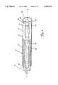
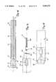
- FIG. 1is a perspective, partially broken away view of a medical device of the invention
- FIG. 2is a perspective view in partial cross section of a distal portion of the device of FIG. 1;
- FIG. 3is a side view and a top view of the rotor housing of the device of FIG. 1;
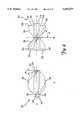
- FIG. 4is a side view and a rotated side view of a preferred embodiment of a rotor of the invention.
- FIG. 5is a cross-sectional view of a preferred embodiment of a rotor housing of the invention.
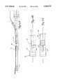
- FIG. 6is a perspective view of the distal portion of an alternative embodiment of the invention utilizing a guidewire tracking channel
- FIG. 7is a cross-sectional view of a preferred drive means for use with the present invention.
- FIG. 8is an end view and an exploded side view of an alternative embodiment of a rotor housing of the invention.
- FIG. 9is an exploded perspective view of a turbine for use in the drive means of FIG. 7;
- FIG. 10is a side view in partial cross section of a distal portion of an alternative embodiment of the invention.
- FIG. 11Aillustrates an alternative embodiment of the invention of FIG. 6, utilizing an alternative guidewire tracking channel
- FIG. 11Bis a top isolation view of a distal portion of the invention of FIG. 11A;
- FIG. 11Cis a side isolation view of a distal portion of the invention of FIG. 11A;
- FIG. 12illustrates an alternative embodiment of a rotor housing of the invention
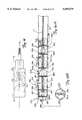
- FIGS. 13A and 13Bare a side elevational view and an end view, respectively, of another embodiment of the invention, which employs a multi-stage rotor design;
- FIG. 14is a side view in partial cross section of a distal portion of yet another embodiment of the invention.
- FIG. 15is a schematic view of a shaft in accordance with one embodiment of the invention.
- FIG. 16is a side view of a distal portion of another embodiment of a housing of the invention.
- FIG. 17Ais a side view of a further embodiment of the present invention employing an inflatable balloon
- FIG. 17Bis a side view of the invention of FIG. 17A with the inflatable balloon in its inflated state;
- FIG. 18is a side view of a further embodiment of the invention which uses an exhaust directing means
- FIG. 19is a side view of another embodiment of the invention which uses an exhaust directing means
- FIGS. 20A and 20Bare a top view and a side view, respectively, of an embodiment of the invention which is generally self-steerable;
- FIG. 21is a schematic side view of a further additional embodiment which can be used to remove macerated thrombi.
- FIGS. 22A and 22Bare top and side elevational views, respectively, of another embodiment of the invention which is generally self-steerable.
- FIGS. 1-4One preferred embodiment of a medical device of the invention is shown in FIGS. 1-4.
- This devicegenerally includes an elongate, flexible shaft 10 carried within an elongate, generally tubular casing 20; a rotor 50 affixed to the shaft and carried within a rotor housing 70; and a drive means 100 operatively connected to the shaft for rotating the shaft.
- the shaft 10is elongate and generally cylindrical in shape and has a distal end 12 and a proximal end 14 (FIG. 7).
- the shaftis sized to be threaded, along with the rest of the device of the invention, along a vascular path within a patient's vascular system.
- the shaftwill commonly have an outer diameter of between about 0.25 and about 1.5 mm, with a range of about 0.35 to about 0.65 mm being preferred.
- the length of the shaftcan be varied fairly widely, depending upon the general types of locations within a vascular system intended to be accessed with the device. As a general rule, the shaft is desirably between about 50 cm and about 150 cm long, with a range of about 80 cm to about 100 cm providing a device which is useful for a wide variety of applications.
- the shaftis desirably highly flexible so that it may be threaded through a patient's vascular system with ease.
- the shaftmay be made of any of a wide variety of materials well known in the art, such as stainless steel.
- the shaftis formed of a shape memory alloy, such as a NiTi alloy.
- NiTi alloysuch as NiTi alloy.
- One important property of such alloysis that they exhibit superelasticity, i.e., they may be deflected to a much greater extent than most other metals, such as stainless steel before showing any permanent, plastic deformation. This property is explained in some detail in U.S. Pat. No.
- the shaftwould tend to take a permanent set, i.e., undergo plastic deformation, as it is guided along a tortuous vascular path. This would introduce a degree of curvature in the distal portion of the shaft 10. When the shaft is rotated, it will not rotate merely about its axis, but will also tend to spin somewhat wildly due to the curvature of the wire. If the shaft includes a rotor for degrading solid matter within the blood stream, this "whip" can readily lead to puncture of the vessel walls, as noted above.
- the shaft 10is formed of a "drawn-brazed strand" (DBS) cable.
- DBSdrawn-brazed strand
- Most cablescomprise a plurality of independent wire strands which are wrapped in a generally helical fashion about a central core wire. Although such a cable does tend to resist plastic deformation somewhat better than a single, unitary wire formed of the same material at the same diameter, the central wire strand of such a cable will tend to undergo plastic deformation to an extent proportional to that experienced by the larger diameter unitary wire.
- a DBS wire of the inventiona plurality of separate strands are wrapped in a helical fashion, but no central wire strand is employed.
- the individual wire strands (not shown) of a DBS wire of the inventionhave been twisted about one another in a helical fashion, it is desirably drawn under pressure at high temperatures. As will be understood by those skilled in the art, this drawing and brazing of the wire can be used to meld the individual wire strands into a single wire having a larger diameter.
- Such a shaftgenerally appears the same as a solid wire, but the wire tends to retain some of the microstructure associated with the intertwined wire strands, yielding a wire with a tensile strength comparable to that of a cable.
- the individual wire strands used to form a DBS wiremay be formed of any suitable material. As with the unitary, single strand shaft described above, the DBS shaft may also be formed of a shape memory alloy such as a NiTi alloy, if so desired.
- FIG. 15illustrates one particularly preferred embodiment of the shaft 10.
- the main body of the shaftmay be as described above, but the shaft includes a weaker point along its length which will selectively structurally fail in the event of a malfunction.
- the shaft 10is formed of two shaft segments 10A and 10B. These two shaft segments are joined together by a shear link 16.
- This shear linkincludes a reduced diameter portion where it joins the two links, defining a relatively weak area of the link.
- This reduced diameter portionshould have a torsional strength less than that of the main body of the shaft so that will tend to break under torsional shear before the rest of the shaft will fail. This makes the device even safer in that the shaft will break at this link 16 when the shaft encounters undue resistance to turning, such as when there is some blockage of the rotor or some other unforeseen malfunction occurs.
- the shear link 16may be positioned at any suitable point along the length of the shaft. In the embodiment shown in FIG. 15, the link 16 is positioned almost immediately proximally of the housing 70. It should be understood, though, that the link 16 could be placed elsewhere, such as adjacent the joint between the shaft and the drive means 100 described below.
- the shaft 10is desirably carried within a shaft casing 20.
- the shaft casingis desirably generally tubular in shape such that the shaft 10 may be retained and rotated within the casing.
- the shaft casing 20desirably extends along and encloses substantially the entire length of the shaft between the drive means 100 and the housing 70.
- the shaft 10should be rotatable within the shaft casing so that, as the drive means 100 causes the shaft to rotate, the shaft casing 20 remains substantially stationary with respect to the drive means.
- the shaft casingshould be flexible and sized to permit it to be threaded along a vascular path as the device of the invention is positioned within a patient's vascular system.
- the shaft casingcomprises a tubular outer sleeve 22 formed of a biologically inactive polymeric compound, such as polyurethane or the like.
- FIG. 6depicts an alternative embodiment of the tubular outer sleeve 22 shown in FIGS. 1 and 2.
- the outer sleeveis generally the same as described above in connection with FIGS. 1 and 2, but the outer sleeve further includes an arcuate projection which extends generally radially outwardly toward one side of the sleeve 22, as shown.
- This projection 24includes a guide wire tracking channel 28 which may extend along substantially the entire length of the projection.
- This tracking channelpermits one to simply direct a guide wire to the desired location within a patient's vascular system and then direct the distal end of the present invention to that location by passing the guide wire through the channel 28 so that the device follows the path of the guide wire accurately.
- the projectiondesirably terminates at a position proximally of the rotor housing 70 so that it does not interfere with the flow of fluid during operation of the device.
- FIGS. 11A-11Cillustrate an alternative embodiment of the invention utilizing a modified guidewire tracking channel 28'.
- the channel 28is positioned in a projection 24 which extends along the casing 20.
- the casing 20is a dual lumen catheter having a larger inner lumen wherein the shaft 10 is disposed and a smaller second lumen which defines a guidewire tracking channel 28', with an inner wall 24' of the casing separating the two lumens.
- This tracking channel 28'extends along substantially the entire length of the casing 20, but terminates slightly proximally of the distal end of the device.
- the channel 28'tapers radially outwardly in a distal direction, leading a guidewire carried therein to relatively gradually slope radially outwardly until it is clear of the casing.
- the channel 28'tapers outwardly at a relatively small angle ⁇ , which is desirably no more than about 35° and preferably between about 1° and about 5°.
- An embodiment having an angle ⁇ of about 3°has been found to work well.
- This taperingwill define a generally elongate exit opening 27 in the casing where the guidewire is to exit the tracking channel 28'.
- the opening 27may extend along both the distal segment of the casing 20 and a proximal portion of the rotor housing 70, as shown in FIGS. 11.
- the exit opening 27is preferably disposed between the ports 74. This will help direct the distal portion of the guidewire between the ports and avoid any interference by the guidewire of the fluid flow established by the ports, which is explained below.
- FIGS. 6 and 11are useful when the device of the invention is to be deployed through a tortuous path or in performing a contralateral introduction. As such, this feature can be used with any of the other embodiments of the invention described herein.
- FIGS. 6 and 11illustrate rotor housings 70 which include a plurality of exhaust ports 74, it is to be understood that the guidewire tracking channel 28 or 28' can also be used with embodiments which do not include any ports 74 (e.g. the self-pumping version of the invention illustrated in FIG. 21).
- the shaft casing 20includes an elongate inner bearing 26 disposed between the outer sleeve 22 of the casing and the shaft 10 to reduce friction between the outer sleeve and the shaft.
- the bearingis desirably free-floating, i.e., it is not attached to any other element of the device, but rather is simply retained between the outer sleeve and the shaft.
- a helical coilas shown in the drawings.
- Such helical coilsare well known in the art and are most commonly used as structural elements of guide wires. They generally comprise an elongate wire strand, usually stainless steel wire, which is wrapped in a helical fashion about a mandrel and then removed from the mandrel.
- the coilwhich is generally formed of a metal such as stainless steel, will tend to act as a heat sink and more evenly distribute the heat to further minimize localized increases in temperature attributable to the friction. Accordingly, this reduces damage to blood and tissue as well as greatly reducing the likelihood of experiencing catastrophic failure of the shaft.
- FIG. 14illustrates another embodiment wherein the coil is fixed at at least one end.
- a coilis also used as the inner bearing 26, but the distal end of the coil is attached to the proximal end of the housing 70.
- the coil and the housingmay be attached by, for example, a braze or solder joint 23; an adhesive material such as an epoxy could be used instead if so desired.
- an adhesive materialsuch as an epoxy could be used instead if so desired.
- a standard "Y-type” connectormay be attached to the outer sleeve 22 toward its distal end.
- These types of connectorsare well known in the medical field and need not be discussed at great length here.
- theyinclude a body portion 32 and an inlet tube 34.
- the body portion 32is generally axially aligned with the outer sleeve 22 while the inlet tube 34 is angled distally outwardly from the body portion 32.
- the inlet tube 34is in fluid communication with the interior of the shaft casing 20, permitting one to introduce any of a wide variety of fluids into the casing.
- the Y-type connectoris replaced by an infusion line 34', which may be formed of a length of flexible tubing or the like.
- the infusion linemay be affixed to the sleeve 36 of the housing of the drive means 100 by means of a Luer fitting 35' or the like.
- the infusion line 34'is in fluid communication with the interior of the shaft casing 20.
- Fluids which may commonly be used in connection with the present deviceinclude saline solution, contrast medium (for enhancing the radiographic visibility of the device) and fibrinolytic solutions (for medically breaking down fibrin, a major component of most thrombi).
- saline solutionfor enhancing the radiographic visibility of the device
- fibrinolytic solutionsfor medically breaking down fibrin, a major component of most thrombi.
- a rotor 50which may also be referred to as an "impeller," is affixed to the shaft 10 adjacent the distal end thereof for rotation therewith.
- the rotor 50generally includes a central body 52 having at least one blade 56 carried thereon.
- the central body 52is desirably generally tubular in shape, having a cylindrical aperture 54 extending through the body along the axis thereof. As explained in more detail below, this aperture 54 is intended for receiving a portion of the shaft 10 adjacent its distal end 12. Any number of blades 56 may be carried about the central body 52.
- the rotor 50includes a pair of generally diametrically opposed blades 56 which extend generally radially outwardly of the central body 52.
- each of the bladesis semi-elliptical in shape and is positioned diametrically opposite the other blade.
- Each bladeis desirably positioned within a plane which obliquely intersects the axis A of the shaft, and the opposite blade is substantially a mirror image of the first blade.
- This constructionis not unlike that of the propeller of a prop-style airplane, the oblique orientation of the blades 56 causing fluid to be thrust generally axially rearwardly of the rotor when the rotor is caused to rotate.
- FIGS. 4A and BA particularly preferred embodiment of a rotor of the invention is shown in FIGS. 4A and B.
- the bladesextend generally radially outwardly of the body 52 from diametrically opposite locations.
- each bladespirals in a generally helical fashion along the length of the body.
- each bladeextends about approximately 180° of the circumference of the body 52 between the blade's proximal 58 and distal 60 ends.
- the rate at which the blade 56 follows around the circumference of the body along its lengthcan be varied as desired.
- a plane within which a segment of the blade liesis oriented at an angle theta ( ⁇ ) of approximately 40° from a plane orthogonal to the axis A of the body 52.
- fibrinis generally formed of elongate strands of a proteinaceous material.
- fibrinwill tend to become wrapped around the body 52 of the rotor if the rotor is not accelerated from an initial stationary position to full rotational speed quickly enough.
- the drive means 100 of the inventionis intended to permit sufficient torque to be applied to the shaft 10 to reach maximum rotational speed rather quickly to avoid this problem.
- a sharpened leading edge 62may be provided adjacent the distal end 60 of each blade 56.
- the leading edge of the bladesdo not lie in a plane orthogonal to the axis A of the body 52 as do the trailing edges 64 at the proximal end 58 of the blades. Instead, the leading edge lies within a plane which is angularly displaced from an orthogonal plane through an angle alpha.
- This angle alphais desirably between about 30° and about 60°, with a range of between about 40° and about 45° being preferred. This provides a sharp, acute angle at the distal end of the blade, permitting the sharpened distal edge of the blade to slice the fibrin before it can become twisted about the rotor.
- the rotormay be affixed to the shaft by any suitable means.
- a distal portion of the shaft 10is received within the aperture 54 formed in the body 52 of the rotor.
- the shaftmay then be permanently adhered to the rotor in any desirable fashion, such as by brazing or by means of a curable, biologically inert cementitious material.
- a thrombectomy device of the inventionalso includes a rotor housing 70 carried about the rotor and within which the rotor rotates.
- the housingcomprises a generally cylindrical wall 72 having an inner diameter greater than the outer diameter of the rotor 50 so that the rotor may freely rotate within this housing.
- the inner diameter of the housing 70is only slightly greater than the outer diameter of the rotor 50. This close proximity between the rotor and the wall 72 of the housing increases the shear force applied to a fluid passing through the housing as the rotor is rotated. This heightened shear force will serve to further break up the thrombus carried within the blood, permitting the rotor to more rapidly degrade a thrombus entrained in the fluid into sufficiently small particles.
- the axis A H of the housing 70is desirably substantially aligned with the axes of the rotor 50 and shaft 10.
- the rotor housing 70includes a plurality of ports 74 which pass through the cylindrical wall 72.
- the portsare desirably spaced equiangularly about the circumference of the housing.
- the rotor 50is desirably positioned generally toward the distal end 78 of the housing, as shown in FIG. 2.
- the ports 74are positioned about the wall 72 of the housing immediately distally behind the rotor 50.
- the low pressure adjacent the distal end of the rotortends to draw the blood being expelled through the ports back through the rotor, thereby creating a recirculating vortex wherein a substantial portion of the fluid exiting through the ports tends to pass through the rotor repeatedly.
- the rotorWhen a thrombus is drawn into the housing by the rotor, the rotor will tend to divide it into a number of smaller particles, which may well remain too large. However, these particles will be entrained in the blood expelled through the ports and will therefore tend to be drawn back into the rotor and become degraded even further. After a sufficient number of passes through this recirculating vortex, the thrombus may be broken into a large number of very small, discrete particles. These particles may be made small enough to substantially eliminate the risk that they would tend to cause blood to coagulate about them again to produce additional thrombi or cause any distal embolization.
- the rotorWhen in use, the rotor will usually be positioned within the confines of a vascular channel adjacent the location, or suspected location, of a thrombus. When the rotor is rotated and causes blood to be ejected through the ports 74, the ejected fluid will impinge upon the vascular wall, tending to urge the housing away from the vascular wall as a reaction to this impinging fluid. If each of the three or more equiangularly spaced ports are of substantially the same size, the fluid volume passing through each port and the rate at which the fluid is expelled from the ports will be substantially equivalent.
- the reactionary force acting against the housing to urge the housing away from the vascular wallwill become equalized when each of the plurality of equiangularly spaced, similarly sized ports are approximately the same distance away from the vascular wall.
- the fluid flowing through the ports in the housingwill tend to automatically center the housing and the rotor within the vascular channel when the rotor rotates.
- the housingwill not only automatically be centered when in use, but it will tend to remain centered within the vascular channel. If only two ports are utilized (as in the device shown in FIG. 1), though, the housing may not remain centered. The fluid expelled through the two diametrically opposed ports will tend to ensure that the housing remains equally spaced from portions of the vascular wall along a line passing through both of the ports, i.e., in a horizontal plane in FIG. 1.
- FIG. 12shows a modification of the ports shown in, e.g. FIG. 3, which has been found to further optimize the recirculation of the fluid flowing through the housing 70.
- the major axes P of the generally elliptical ports 74 in that embodimentare generally parallel to the axis A H of the generally cylindrical wall 72 of the rotor housing.
- the major axes P of the portsare disposed oblique to the axis A H of the housing.
- the major axes P of the ellipsesare technically arcuate and wrap about the axis A H of the housing, the degree of offset between the generally parallel axes P of the ports can be expressed as an angle ⁇ , as shown.
- An angle ⁇ of about 20° to about 45°has been found to help direct the fluid exiting the housing through the ports 74 toward the distal end of the housing, making the recirculating vortex of fluid more efficient and ensuring even more thorough maceration of the thrombi entrained therein in the same amount of time.
- FIG. 13illustrates an alternative embodiment of the invention which utilizes a multi-stage rotor design.
- the single rotor 50 of the embodiments discussed aboveis replaced with a series of individual rotors 50A, 50B and 50C.
- Each of these rotorsmay be shaped generally as outlined above and are each attached to the same shaft 10 for rotation therewith.
- the housing 270 of this embodimentis elongated to accommodate all three rotors. Although the housing 270 may be formed entirely of metal or the like, having such an elongated, rigid housing may impair the ability to guide the rotors to a site in a patient's vascular system which may require following a tortuous path.
- the elongate, generally cylindrical wall 272 of the housing 270is optimally formed of a flexible material, such as a polymeric material commonly used in forming catheters.
- the invention of FIG. 13utilizes a distal segment of the casing 20--which may be a catheter, as noted above--as the wall 272 of the housing.
- each rotormay be provided with a separate sub-housing 280A-280C which encloses the rotor.
- Each sub-housing 280includes a generally cylindrical wall 282, which may be formed of metal or the like, received within the more flexible wall 272 of the main housing 270. This wall 282 of the sub-housing is optimally adapted to fit relatively snugly within the lumen of the main wall 272 to limit relative movement of these walls.
- Each sub-housingalso includes a forward strut 284 and a rearward strut 286, with each strut having a rotation sleeve 288 for rotatable receiving the shaft 10 therethrough.
- These strutsserve to provide structural support to the sub-housings 280 and passing the shaft 10 through the sleeves 288 in these struts serves to fix the relative positions of the sub-housings and the shaft.
- the sleeves 288also serve to position the rotor within the sub-housing assemblies, both centering the rotor within the circumference of the wall 282 and preventing any undue axial movement of the rotors within the sub-housings.
- the first rotor 50Acan simply draw fluid in through the distal end of the housing.
- a single set of exhaust ports 274may be provided adjacent the distal end of the housing 270. These exhaust ports 274 are desirably spaced generally equiangularly about the circumference of the housing 270 and serve much the same functions as the ports 74 in the embodiments outlined above, e.g. assisting recirculation of the fluid past the rotors and helping to center the housing within a vessel.
- the sub-housings 280A-280C and their associated rotors 50A-50C, respectively,may be thought of as effectively defining three separate maceration zones.
- Exhaust ports 274are positioned at the rearward end of each of these zones, i.e. at a location spaced slightly proximally of the associated rotor. In the embodiment shown in FIG. 13A, these exhaust ports 274 are positioned rearwardly of the sub-housing 280 and need only extend through the cylindrical wall 272 of the main housing 270.
- a set of equiangularly spaced intake ports 276is also provided for each of the two proximally spaced rotors, 50B and 50C, with the intake ports 276 being positioned generally distally of the associated sub-housings 280B and 280C, respectively.
- each set of exhaust ports 274 and each set of intake ports 276comprises four equiangularly spaced ports, with the exhaust and intake ports being axially aligned so that one intake port will be positioned immediately distally of the adjacent exhaust ports.
- the main path of fluid flowis schematically depicted by arrows in FIG. 13A.
- the distal rotor 50Awill draw fluid into the housing 270 through the open distal end of the housing. After the fluid passes over the first rotor, it will tend to exit the housing through the exhaust ports 274. A substantial portion of the expelled fluid will then reenter the housing through the intake ports 276 for maceration by the second rotor, 50B while the remainder of the expelled fluid will be drawn back toward the distal end of the housing for another pass by the first rotor 50A.
- the fluidwill once again exit the housing 270 through exhaust ports 274 positioned behind the sub-housing 280B and reenter the housing through intake ports 276 disposed in front of the third rotor 50C. Finally, fluid will exit the housing through the last set of exhaust ports 274 stationed proximally of the third sub-housing 280C.
- optional bulkheads 290may be positioned between the rotors.
- These bulkheadsmay be relatively thin struts such as the struts 284, 286 of the sub-housing assemblies and be utilized simply to support the relatively flexible wall 272 of the main housing to prevent it from being inadvertently drawn into one of the rotor housings 280B, 280C during operation.
- the bulkheadsmay be present a larger surface area, e.g. generally disc-shaped bulkheads having centrally located openings through which the shaft may pass.
- the bulkheadsare ideally placed between adjacent sets of exhaust ports 274 and intake ports 276, as shown.
- the housing 70may be provided with a generally inwardly extending distal bead 76 adjacent its distal end.
- This distal beadis desirably rounded to provide the housing with a rounded distal end 78 for contacting tissue as the device is deployed within a vascular system.
- the distal beadmay be formed on the housing by inwardly deforming a distal portion of the cylindrical wall to form an annular bead disposed within a distal segment of the housing.
- FIG. 5depicts one useful shape
- FIG. 8shows an alternative embodiment of such a bead.
- Such a rounded distal end 78tends to be less traumatic than either the more blunt distal end 78 shown in FIG. 2 or an exposed rotor 50 which is not surrounded by a housing, as is most common in the prior art.
- this distal bead 76is desirably generally inwardly extending, though it may also extend outwardly of the cylindrical wall 72 of the housing.
- the inner diameter of the housing adjacent its distal end, i.e., adjacent the distal bead 76,is desirably less than the maximum outer diameter of the rotor 50. This serves as a further safety measure in that if the shaft 10 breaks, the rotor will be unable to pass through the distal end of the housing. This prevents the rotor and a broken off distal portion of the shaft from becoming left within the blood stream of the patient if the shaft does indeed fail.
- FIG. 16shows an alternative embodiment of a distal end 78 of a housing for use with the invention.
- the housingwas provided with a rounded tip by means of a distal bead 76 formed integrally with the housing.
- the distal bead 76'is formed of a relatively soft polymeric material, such as by molding the bead from a plastic commonly used in forming catheters and the like.
- the distal end of the cylindrical wall 72 of the housingdesirably tapers inwardly to form a restrictive flange 75, to which the distal bead 76' may be attached.
- This flange 75desirably extends inwardly sufficiently to ensure that the distal end of the housing has a smaller diameter than the diameter of the rotor 50 to ensure that the rotor will be retained within the housing in the case of a broken shaft or the like.
- FIG. 8depicts an alternative construction of the housing 70 of the invention.
- the housingis desirably integrally formed of a single, unitary piece of material, such as surgical stainless steel.
- the housing 70is formed of two separate elements which can be affixed to one another when assembling the invention.
- the cylindrical wall 72which is carried about the rotor forms a first, distal element which can be permanently attached to the other, proximal segment 90 by any suitable means, such as by brazing.
- the proximal segment 90has a central aperture 92 extending centrally therethrough for rotatably receiving the shaft 10 to position a proximal portion of the shaft and the rotor attached thereto in the center of the cylindrical distal segment 72.
- a plurality of fins 79are positioned equiangularly about a generally frustoconical housing insert 94.
- the insert 94 and the finsare sized to be closely received within the confines of the cylindrical wall 72 when the housing is assembled.
- the insertdesirably tapers radially outwardly in a proximal direction from an initial outer diameter only slightly greater than that of the shaft 10 to an outer diameter adjacent its proximal end generally equal to the inner diameter of the cylindrical wall 72. Although this taper may be generally linear, in the preferred embodiment shown the rate of taper is much greater adjacent its proximal end.
- An annular abutment 96may be provided adjacent the proximal end of the housing insert 94.
- This abutmenthas an outer diameter greater than the inner diameter of the cylindrical wall 72 and thus serves to abut the proximal end of the wall when the housing is assembled. If so desired, the wall 72 may be affixed directly to this abutment.
- the outer diameter of the abutment 96is substantially equal to that of the cylindrical wall to provide the housing with a smooth outer surface.
- the housing insert 94may include a plurality of fins 79 positioned equiangularly about its circumference.
- the number of fins employedis desirably equal to the number of ports 74 in the housing, and one fin may be positioned immediately adjacent each port. If so desired, the fins may be parallel to the major axis of their respective, generally elliptical ports.
- any solid matter, such as a thrombus, entrained within the fluidwill strike the fins, which form a part of the housing and are thus stationary with respect to the spinning rotor. Solid matter will tend to be broken up when it impacts the fins, so the fins serve to speed up the degradation of thrombi or the like within the fluid.
- a connector 80may extend proximally of the cylindrical wall 72 of the rotor housing 70 and permit the housing to be attached to the distal end of the shaft casing 20.
- the connector 80includes a first segment 82 adjacent and connected to the cylindrical wall 72 of the housing.
- the outer diameter of this first segment 82is desirably substantially equal to the inner diameter of the outer sleeve 22 of the shaft casing adjacent its distal end so the first segment 82 may be closely received within and retained by a distal portion of the outer sleeve 22.
- the outer diameter of the cylindrical wall 72 of the housingis desirably substantially equal to the outer diameter of the shaft casing 20 to present a relatively smooth outer surface at the junction between the housing and the shaft casing.
- the decrease in diameter between the cylindrical wall 72 and the first segment 82may be relatively abrupt, defining a generally rearwardly facing annular shoulder 84 for abutting the distal end of the outer sleeve 22.
- the first segment 82may be cemented to the lumen of the outer sleeve by means of an epoxy or the like (not shown).
- the connector 80may also include a second segment 86 which is disposed proximally of the first segment 82 and is attached thereto.
- the maximum dimension of this second segmentis desirably larger than the inner diameter of the inner bearing 26. The second segment thus serves to distally limit the axial movement of the inner bearing and serves to retain the bearing in place about the shaft 10 within the outer sleeve 22.
- the second segment 86is generally rectangular in cross section, as indicated in FIGS. 3A and B, rather than being generally cylindrical.
- the second segmentmay be substantially solid in cross section, but includes a central aperture passing therethrough for receiving the shaft 10.
- the axis of this cylindrical apertureis preferably substantially aligned with the axis of the shaft and the aperture is sized to permit the shaft to freely rotate therein.
- the second segmentthus serves to support the shaft in a spaced relationship with respect to the shaft casing 20 and helps to ensure that the rotor is axially centered within the cylindrical wall of the housing rather than abutting against the wall.
- Utilizing a generally rectangularly shaped second segment having maximum dimensions less than the diameter of the first segment 82provides a space between the second segment and the shaft casing 20. This space allows fluids, such as the contrast mediums or fibrinolytic solutions noted above, to pass distally from within the casing through the housing and into the vascular channel.
- FIG. 10depicts an alternative embodiment of a rotor housing 70 and connector 80 of the invention.
- the connectordoes not include a second segment 86 disposed rearwardly of the first section 82.
- a coiled support member 86'is utilized.
- the support member 86'is carried within the first segment 82 and extends along the length thereof from a position adjacent the annular shoulder 84 to the proximal end of the first segment.
- the support memberdesirably comprises a widely spaced helical coil formed of a wire having a diameter adapted to extend radially inwardly of the first segment a sufficient distance to provide lateral support to the shaft 10 carried within the helical coil.
- the axes of the shaft, the first segment and the helical support member 86'are desirably substantially aligned with one another.
- Adjacent turns of the helically coiled wireare desirably spaced apart from one another. This permits fluid to pass through the support member 86' at relatively high flow rates as the space between the adjacent turns effectively defines a generally helical path along which fluid may freely flow between the interior of the shaft casing 20 and the rotor housing 70.
- the direction of this fluid flowis schematically represented by arrows in FIG. 10 and, as indicated by the bi-directional character of these arrows, fluid may flow in either direction along this helical channel--if one is aspirating fluid from within the vascular channel, the fluid would flow generally proximally, while fluid would flow generally distally if one were delivering a fibrinolytic solution or the like into the vessel through the shaft casing.
- FIGS. 22A and 22Billustrate yet another embodiment of the housing 70 and connector 80 of the invention.
- the first section 82'is adapted to be directly connected to the bearing 26 (not shown in FIG. 22) within the casing 20.
- the first section 82'has a generally helical slot 83 extending about its surface.
- This slot 83should be adapted to receive a distal portion of the bearing, which is desirably a helically would coil, as noted above.
- the pitch of the coilshould be adapted to permit the coil to be readily threaded into the helical slot 83 in the connector 80.
- the bearing 26can then be affixed to the connector 80, such as by brazing the coil to the connector or connecting these elements with a suitable adhesive. When assembled, this connection between the bearing and the connector may have an appearance substantially as shown in FIG. 14 and described above in connection with that drawing.
- the connector 80 of the housingis desirably also provided with a shaft support sleeve 88 for supportingly receiving a portion of the shaft adjacent its distal end.
- the support sleeve 88may be of any desired construction, but preferably comprises a thin-walled stainless steel tube, known in the art as a "hypotube,” having a length of between about 0.25 and about 0.35 inches.
- the sleeveis sized to permit the shaft to rotate freely therein, yet limit lateral movement of the shaft so that it may stabilize the shaft in a position wherein the axis of its distal portion is substantially aligned with the axis A H of the housing.
- the support sleeve 88may extend distally through the first 82 and second 86 segments of the housing (or the first segment 82 and the support member 86' in the embodiment of FIG. 10) to a position within the rotor housing 70 immediately adjacent the rotor 50 (as best seen in FIGS. 2 and 10).
- FIGS. 17-19illustrate embodiments of the invention which utilize fluid directing means to direct fluid exiting through the exhaust ports 74 back toward the distal end of the housing for further maceration. This serves to further ensure that fluid will be efficiently recirculated toward the distal end of the housing to ensure that any thrombi present are thoroughly macerated.
- the fluid directing meansis optimally expandable from a collapsed state useful for deployment of the invention in a patient's vascular system to an expanded position wherein it is directing fluid for recirculation.
- a balloonserves as the fluid directing means.
- the casing 220 of this inventionprovides a selectively inflatable balloon 222 about a distal section 224 of the casing.
- This "balloon catheter”includes a separate inflation lumen 226 through which an inflation fluid may be passed and ports 228 deliver fluid from the inflation lumen 226 to the interior of the balloon 222 to inflate the balloon.
- the balloonmay also be deflated in mush the same fashion, with the fluid being withdrawn from the interior of the balloon through the inflation lumen 226 via the ports 228.
- Such “balloon catheters”are well known in the art and need not be discussed at great length here.
- the devicewill be positioned in a patient's vascular system at the desired location for treatment.
- the ballooncan then be inflated until it engages the sidewall of the vessel, substantially filling the lumen of the vessel.
- the balloonmay be inflated with any suitable fluid which may be subsequently withdrawn to deflate the balloon so that the device can be withdrawn when the operation is complete.
- a fluidwhich is biocompatible, e.g. a radiopaque contrast medium or a saline solution, so that no harm will be done to the patient if the balloon accidently ruptures.
- the inflated balloon 222serves two functions. First, fluid will be effectively prevented from travelling proximally beyond the balloon. As the fluid is ejected from the exhaust port or ports 74 it will be readily drawn back up to the distal end of the housing for another pass over the rotor, promoting the recirculation of the fluid to thoroughly degrade any thrombi entrained in the fluid. This can be particularly helpful in situations where the risk of even relatively small thrombi being left after the procedure is higher than normal, as in cardiac or cerebral applications. Second, the inflated balloon 222 will help to center the housing in a larger vessel to reduce the likelihood that the vessel wall will be injured by the rotor in any way.
- FIGS. 18 and 19provide alternative fluid directing means for providing efficient recirculation of fluid in much the same manner as the balloon 222 of FIG. 17.
- the fluid directing meanscomprises a flexible sheath 240 which extends about a distal portion of the casing 20 and a proximal portion of the housing 70.
- This sheath 240is desirably formed of a relatively flexible elastomeric material, such as a latex material such as that commonly used in the balloons of balloon catheters or the like.
- the sheath 240should be adapted to be carried along the housing 70 and the casing 20; optimally, the sheath is sized so that it will fairly snugly engage the outer surfaces of these elements.
- the sheath 240should be attached to the casing 20 at a point proximal of the exhaust ports 74 and extend distally to substantially cover these ports.
- the sheathwill lie against the ports and may substantially seal the ports.
- the rotorWhen the rotor is engaged, though, it will tend to thrust fluid out of the exhaust ports, as noted above. The force of the fluid exiting these ports will tend to inflate the sheath 240. Since the sheath is fixed adjacent its proximal end to the casing 20, the distal end of the sheath will be more inflated than the proximal end, yielding a generally frustoconical structure as shown in FIG. 18. As shown schematically by the arrows in this drawing, this will tend to direct the fluid exiting the ports back toward the distal end of the housing for another pass through the rotor.
- the fluid directing means of FIG. 19comprises a plurality of normally closed gates 250.
- the operation of these gatesis similar to that of the sheath 240 of FIG. 18.
- one gate 250is associated with each exhaust port 74 of the housing.
- the gatesare hingedly connected to either the housing 70 or the casing 20 at a location disposed proximally of the ports 74.
- the gates 250are biased toward a closed position wherein they engage the housing to generally cover the ports 74 by any suitable means, such as with a leaf spring or the like.
- the sheath 240 of FIG. 18when the rotor is engaged, the fluid being expelled from the housing through the ports 74 will urge the gates away from the housing and the gates will tend to redirect the fluid distally for recirculation.
- the fluid directing meanscould be relatively rigid and always be in he configuration used to redirect fluid distally for recirculation.
- deployment of the device of FIG. 19 in a patient's vascular systemcould be hampered if the gates 250 were to remain in the position shown in the drawing.
- the fluid directing meansbe selectively configurable between a relatively compact deployment configuration and an expanded configuration for redirection of fluid, it is to be understood that a permanent structure could instead be employed.
- the housing 70generally includes a plurality of generally equiangularly spaced exhaust ports 74 which serve to substantially center the housing within a vessel when the rotor is rotated. As detailed above, this has some distinct advantages.
- a single exhaust port 74is provided in the housing 70 and this port preferably extends about no more than about 50% of the circumference of the housing, and desirably extends about substantially less than 50% of the housing's circumference.
- rotation of the rotorwill cause fluid to flow rearwardly, whereupon it is expelled through the single exhaust port 74. This will tend to deflect the housing toward one side of the vessel.
- this directional urging of the distal segment of the devicecan be used to help deploy the device within a patient's vascular system.
- a guidewireWhen deploying a device of the earlier embodiments of the invention, a guidewire will generally be guided to a desired location within the vascular system by observing progress of the guidewire on a fluoroscope of the like and positioning the distal end of the guidewire adjacent an identified thrombus in the vascular system.
- the device of the inventionwill generally follow the guidewire, as explained above, so that it can be positioned for treatment.
- the rotorwill not be rotated by the drive means until the housing is in the selected position for treating the patient.
- the devicecan be urged distally within the patient's vascular system.
- the rotorcan be activated. This will cause the distal end of the device to be bent generally toward one wall of the vessel.
- the direction in which the distal end of the device is bent with respect to the vascular channelcan be altered as desired.
- the devicecan once again be urged distally to move the housing into the desired branch.
- the rotorcan be then deactivated until it is need to orient the device toward a particular path. This process can be repeated as necessary until the desired treatment site is reached, whereupon the thrombus can be macerated by the rotor as explained in some detail above.
- Utilizing a single port as shown in FIGS. 20A and 20Bconsequently permits an operator to steer the device within a patient's vascular system without need of a guidewire or the like. Not only can this self-steering feature potentially simplify the deployment process by eliminating the need to separately introduce and deploy a guidewire, this can also reduce the overall diameter of the device by eliminating the need for additional structure to track the guidewire, such as guidewire tracking channels 28 and 28'. This reduction in diameter can permit the device to be used in smaller vessels which may otherwise be unreachable.
- FIG. 22also illustrates an alternative housing design which permits the device to be steered during deployment by rotating the rotor.
- this housing designthree or more exhaust ports 74, 75 are provided on the housing 70 for discharging fluid through the wall 72 of the housing when the rotor is rotated. These ports 74, 75 are desirably spaced generally equiangularly about the housing, as in the embodiments detailed above. Any suitable number of ports may be used; in the embodiment shown in FIGS. 22A and 22B, three ports are used, with each port being spaced from the other by about 120°.
- the two ports identified by reference number 74are substantially the same size, but a third port 75 is substantially smaller than the main discharge ports.
- a third port 75is substantially smaller than the main discharge ports.
- the present embodiment of the inventionneed not use only three ports nor have a single port smaller than the other ports in order to achieve similar self-steering properties.
- four portscan be used, with two of the ports being smaller than the other two ports, which would induce the housing to deflect in a direction between the two smaller ports.
- this principlecan be used to produce a self-steerable housing which can be advanced into position within a patient's vascular system substantially as described above in connection with FIGS. 20A and 20B.
- the device of the inventionis quite effective at macerating clots and the like and only a rather small fraction of the clot will remain over about 100 microns in size.
- most prior art devicesutilize aspiration to suction off fluid during operation of a thrombectomy or atherectomy device to remove unwanted clot.
- the generally rearward thrust of the present rotorcan be employed to effectively pump fluid rearwardly for disposal outside of the patient's blood without any requiring any separate aspiration equipment.
- FIG. 21illustrates one particularly preferred embodiment of a self-pumping maceration device of the invention.
- the housing 70which may be located at the distal end of the casing 320, does not include any exhaust ports. Instead, all of the fluid entering the distal end of the housing will be retained within the device and thrust generally rearwardly by rotation of the rotor.
- the rotor of the inventionis desirably a "screw type" rotor having two or more generally helical blades 56 which are oriented at an angle with respect to the main shaft of the rotor. Since the rotor is enclosed within a sealed housing, such a rotor will effectively serve as a positive displacement pump and will urge the fluid drawn into the housing rearwardly and out of the proximal end of the casing.
- the volume of the displacement of the rotor for each turnis relatively small, when the rotor is operated at relatively high speeds (such as the 100,000-135,000 rpm which is deemed to be optimal), the net volume of fluid being displaced may be sufficient to ensure that the macerated thrombi are pumped proximally out of the patient's system.
- FIG. 21illustrates one embodiment of such a device in accordance with the invention.
- a second rotor 350is disposed proximally of the primary maceration rotor 50.
- This second rotoris desirably affixed to the same shaft 10 as the forward rotor 50 so that both rotors will rotate together.
- the rotor 350is carried within a sub-housing 370 having a generally cylindrical wall adapted to fit within the lumen of the casing 320 and a pair of end struts 374, 376 for providing structural support to the sub-housing.
- This sub-housing 370is directly analogous to the sub-housings 280 of the multi-stage maceration embodiment shown in FIGS. 13A and 13B.
- the forward rotorwill tend to macerate thrombi and degrade any fibrin in the thrombi to yield a more homogenous, flowable fluid, so the second rotor 350 need not perform any great deal of maceration. Instead, the primary purpose of the second rotor 350 is to serve as a booster to assist in the pumping of the fluid. Although only a single booster rotor 350 is shown in FIG. 21, it is to be understood that any number of rotors can be spaced along the length of the casing to achieve the necessary flow of fluid therethrough.
- the proximal booster rotor 350 of FIG. 21is substantially larger than the forward rotor 50. This permits the booster rotor to displace even more fluid at the same rotational speed, thereby enhancing the pumping action of the device.
- This booster rotor 350is desirably spaced a considerable distance proximally of the forward rotor 50. This will permit the forward housing 70 to be guided into relatively small vessels, e.g. for treatment of thrombi in cardiac and cerebral vessels, while the booster rotor can remain in a larger vessel.
- the casing 320 of this inventionoptimally has a smaller diameter at its distal end adjacent the first housing 70 and a relatively large diameter along a proximal length 324.
- the casinghas an elongate distal segment 322 having a first diameter, an elongate proximal segment 324 having a second, larger diameter and a tapered segment 326 disposed between the distal 322 and proximal 324 segments. This tapered portion eliminates any sharp discontinuities in the flexibility and other mechanical properties of the casing 320 to minimize any problems in deployment.
- the relative lengths of the distal, proximal and tapered segmentsmay be varied as desired for specific applications.
- the distal segmentis about 10 cm to about 30 cm in length with an outer diameter of about 5.0 French and the tapered segment tapers relatively gradually from this 5.0 French distal segment to a 8.0 French proximal segment over a length of about 10 cm to about 25 cm.
- the proximal segmentcan be of any desired length which permits the distal end of the housing to be positioned at the desired treatment location within a patient's vascular system; a length of between about 50 cm and about 80 cm should work well.
- the present inventionalso includes a drive means 100 for rotating the shaft 10 within the shaft casing 20 to cause the rotor 50 to rotate.
- a drive means 100for rotating the shaft 10 within the shaft casing 20 to cause the rotor 50 to rotate.
- Any suitable drive meansmay be used, but it is preferred that the drive means be capable of rapidly rotating the shaft and the rotor.
- a rotor of the inventionis desirably rotated at speeds between about 80,000 and about 150,000 rpm, with an operating range of between about 100,000-135,000 rpm being preferred.
- this drive meansmay be of any type which will rotate the shaft 10 and rotor 50 at the desired speed, such as a high-speed electric motor, in a preferred embodiment an air-driven turbine is employed.
- this drive meansincludes a housing 102 having first and second sections (104 and 106, respectively).
- the first and second sections 104, 106are adapted to be sealingly affixed to one another to define a short, substantially air-tight cylinder.
- the first section 104desirably comprises a substantially flat, circular disc.
- the second section 106comprises a generally flat, circular distal face 110 and a peripheral wall 108 extends generally perpendicularly laterally from this face 110.
- the diameter of the first section 104 of the housingis greater than the inner diameter of the peripheral wall 108 and may be substantially equal to the outer diameter of that wall.
- the housingmay be formed of any suitable material, in the preferred embodiment it is formed of a polymeric material, such as a high density, machinable plastic, which may be sonically welded to permit the first and second sections 104, 106 to be sealingly affixed to one another with ease.
- an air inlet 120 and an air outlet 134may be provided in and extend radially outwardly through the peripheral wall 108.
- the air inletincludes an inlet tube 124 which extends through the inlet port 122 in the housing and is adapted for attachment to an air supply.
- a pressurized air supplyis provided, with pressures usually in the range of about 35 to about 50 psi.
- the inlet tubeis preferably configured to be sealingly received within and retained at one end of a length of flexible hosing (not shown), the other end of which may be operatively attached to the pressurized air supply to direct pressurized air to the drive means 100 through the inlet tube 124.
- the drive means 100desirably also includes an air outlet 134.
- This air outletallows air to escape the housing 102 so that a continuous flow of air may flow into the housing through the air inlet 120.
- the air outlet 134may be positioned substantially anywhere on the housing. In the embodiment shown in FIG. 1, though, the air outlet comprises a port which extends radially outwardly through the peripheral wall 108. In a particularly preferred embodiment, the air outlet 134 is positioned about the circumference of the peripheral wall relatively close to the air inlet in a direction opposite the direction of flow of air within the housing (generally clockwise in FIG. 1).
- the air outletis provided with an outlet tube 138 carried externally of the housing to direct the flow of air exiting the housing.
- FIG. 7An alternative embodiment of a drive means 100 which has been found to work particularly well with the present invention is shown in FIG. 7.
- the construction of this drive meansis similar to that described above for the embodiment of FIG. 1.
- the housing 102has a generally flat, circular first section 104 which is sealingly affixed to the second section 106 to define a short, substantially air-tight cylindrical housing.
- this housingis desirably formed of a machinable polymeric material which may be sonically welded to sealingly affix the first and second sections 104, 106 to one another.
- the positions of the air inlet 120 and air outlet 134 in this embodimentdiffer from those in the embodiment shown in FIG. 1, though.
- both the air inlet and the air outletpass through the first section 104 of the housing, i.e., at the housing's proximal end.
- the air inlet 120includes an inlet port 122 which passes through the first section 104 of the housing and within which is retained an inlet tube 124.
- An air supply connector 126may be provided for sealingly receiving an air supply, such as a length of flexible housing 123, in fluid communication with the inlet tube 124.
- the inlet tube 124includes a terminal segment 130 which is positioned immediately adjacent the turbine 150, as explained in more detail below.
- a venturi segment 128is provided in the inlet tube between the proximal end of the inlet tube and the terminal segment 130.
- the venturi segmenthas a larger diameter at its proximal end than at its distal end where it is sealingly affixed to the terminal segment.
- this relatively rapid drop in cross sectional area along the venturi segmentwill tend to accelerate the flow of fluid, i.e., air, as it passes from the air supply to the terminal segment 130 of the inlet tube.
- the axis of the inlet tube 124is desirably substantially aligned with the axis of the generally cylindrical housing 102 so that the terminal segment 130 of the inlet tube may be positioned centrally within the housing immediately adjacent the axis of the turbine 150, as explained below.
- the air outlet 134 of the present embodimentdesirably passes through the first section 104 of the housing 102. In this manner, air may be vented rearwardly out of the housing.
- the air outlet 134includes an outlet port 136 which extends through the first section 104 of the housing.
- a plurality of such outlet portsare utilized, the outlet ports being spaced equiangularly about the axis of the cylindrical housing with the axes (not shown) of the outlet ports 136 being generally parallel to and spaced radially outwardly from the axis of the housing.
- a baffle means 140may be provided in each outlet port 136 to diffuse the flow of air out of the housing.
- the baffle means 140comprises a generally porous, sponge-like material which dampens the flow of air, yet permits air to pass therethrough.
- the drive means 100also includes a turbine 150 which may be caused to rotate by the flow of air through the inlet tube 124 of the air inlet.
- a turbine 150which may be caused to rotate by the flow of air through the inlet tube 124 of the air inlet.
- Any of a wide variety of suitable turbinesmay be utilized, but a preferred embodiment of a turbine for use with the present invention is shown in FIGS. 7 and 9.
- This turbine 150may be formed as two separate elements, i.e., a distal segment 152 and a proximal segment 154, which are joined together to produce the turbine after being independently formed.
- the distal segment 152 of the turbineis generally disk-shaped and includes a plurality of generally triangular, wedge-sharped upright projections 156 spaced about its periphery.
- Opposing walls of adjacent projectionsare desirably spaced apart from and generally parallel to one another to define an uprightly open channel 158 therebetween.
- the wedges and resulting channelsare desirably spaced equiangularly about the periphery of the distal segment 152.
- the upright projections 156desirably do not extend all the way to the center of the disk-shaped distal segment, but rather extend inwardly from the periphery a specified distance, which may be on the order of one-half the radius of the distal segment 152.
- the channels 158are desirably oriented generally tangentially with respect to the periphery of this central portion 160 so that as air strikes the center of the turbine, as explained in more detail below, it will be urged tangentially outwardly through the channels 158 and cause the turbine to spin.
- the central portion 160 of the distal segment of the turbineis generally conical in shape and comes to a peak 162 generally along the axis of the disk-shaped distal segment.
- the central portion 160has a generally elliptical profile (as best seen in the cross sectional view of FIG. 7) rather than having a substantially flat incline.
- the proximal portion 154 of the turbineis also generally disk-shaped and desirably has an outer diameter substantially equal to that of the distal segment 152.
- the proximal segmentgenerally includes a central portion 170 and a peripheral portion 169 extending radially outwardly of the central portion.
- the peripheral portion 169includes a plurality of fingers 168 which extend generally tangentially outwardly of the central portion 170. These fingers are adapted to be matingly received within, and fill a portion of, the channels 158 in the distal segment 152.
- the fingers 168are generally rectangular in cross section and extend generally downwardly in FIG.
- the fingersmay be varied as desired, they desirably extend downwardly within the channels 158 to a depth of approximately one-half the depth of the channel.
- the distal and proximal segments 152, 154are desirably formed of an injection moldable polymeric material which may be sonically welded. This permits the individual segments to be accurately and inexpensively produced by injection molding and permits the segments to be permanently affixed to one another by the process of sonic welding. If so desired, a plurality of sacrificial nibs 166 may be spaced about the proximal and/or distal segments. During the sonic welding process, these sacrificial nibs will be broken down and will serve as a weldment for securely attaching the proximal and distal segments to one another.
- the central portion 170 of the proximal segment 154desirably includes a centrally located, generally frustoconical cap 174.
- the capWhen the turbine 150 is assembled, the cap will be spaced away from the central portion 160 of the distal segment to define an air flow chamber (175 in FIG. 7) therebetween.
- the capincludes a central port 176 through which a stream of air may pass and an upstanding lip 177 may be provided about this port. The thickness of the lip 177 may decrease proximally, as shown in FIG. 7.
- the axis of the turbine 150substantially coincides with that of the housing 102 of the drive means and inlet tube 124 of the air inlet.
- the turbineis positioned immediately distally of the inlet tube.
- the upstanding lip 177 of the proximal segment 154 of the turbineis desirably positioned immediately adjacent the distal end of the terminal segment 130 of the inlet tube; if so desired, a short length of the lip 177 may even be rotatably positioned within the distal end of the terminal segment. This ensures that air flowing into the drive means through the inlet tube 124 will flow directly into the chamber 175 of the turbine.
- venturi segment 128 of the inlet tubeserves to accelerate the flow of air through the tube.
- the airthus enters the chamber 175 at a rather high flow rate, which serves to relatively rapidly accelerate the turbine to its full rotational velocity.
- the moment of inertia of the turbinewill be reduced and the turbine may be accelerated even more rapidly.
- the shaft 10 of the deviceis connected to the turbine 150 for rotation therewith by means of a drive coupling 180.
- the drive couplingmay be attached to the turbine and the shaft by any suitable means.
- the turbineincludes a generally cylindrical drive coupling recess for receiving the tubular drive coupling 180 and the drive coupling may be fixed within this recess.
- the drive coupling 180desirably also includes a central recess (not separately shown) within which the shaft 10 may be received and within which the shaft may be affixed.
- the drive means 100desirably includes a distally extending, manually graspable sleeve 36, which may be formed integrally with the second section 106 of the housing. If so desired, the outer surface of this sleeve may be provided with a rougher texture (as shown in FIG. 1) to permit the sleeve to be more readily and more securely grasped by an operator of the device.
- the sleeve 36is desirably tubular in shape and is adapted to receive the drive coupling 180 and a proximal portion of the shaft 10 therewithin. In order to ensure that the axes of the drive coupling 180 and turbine 150 substantially coincide with that of the sleeve 36, bearings 184 may be utilized.
- two sets of bearingsare used, with one being carried adjacent the distal end of the drive coupling and the other being spaced proximally at a location adjacent the drive coupling recess 182 of the turbine.
- Any suitable bearingmay be used, but the bearing should permit the drive coupling 180 to freely rotate with respect to the sleeve 36 as the turbine and shaft are rotated.
- the sleeve 36is elongate in shape and serves to encase structural elements of the device in addition to the drive coupling 180 and bearings 184.
- a spacer 188is carried within the sleeve at a position immediately distally adjacent the drive coupling 180.
- the spaceris generally tubular in shape and is adapted to be closely received within the sleeve 36.
- the spacerincludes a central bore 190 extending through its length, the bore being sized to rotatably receive both the shaft 10 and the inner bearing 26 previously described and support these elements generally centrally along the axis of the sleeve.
- the bearing 26is not affixed to any other element of the device, including the spacer 188, but rather is "free-floating.”
- the spacer 188may be affixed within the lumen of the sleeve 36.
- an O-ring 192 or the likemay be positioned between the spacer and the inner wall of the sleeve. This prevents the fluid used to drive the turbine, i.e., air, from entering the shaft casing 20 and flowing into the bloodstream. Also, it prevents fluids within the casing, such as blood or fluids which are delivered to the casing 20 through infusion line 30', from entering the housing 102 of the drive means.
- a portion of the spacer immediately adjacent the attachment of the infusion line 30' to the sleeve 36is desirably spaced away from the inner wall of the sleeve in order to permit fluid to pass from the infusion line into the casing as previously explained.
- the outer sleeve 22 of the shaft casingmay be affixed directly to the sleeve 36, in a preferred embodiment the outer sleeve is affixed to a swivel connector 194 retained by the sleeve.
- the swivel connectorincludes a body 196 which is retained within the lumen of the sleeve and a distal extension 195 which protrudes distally out of the sleeve through the sleeve's distal exit 38.
- an O-ring 196may be disposed between the body 196 of the swivel connector and the sleeve 36.
- the swivel connectoris desirably rotatable within the lumen of the sleeve, and a bushing 198 or the like may be utilized to ensure that the swivel connector can rotate freely with respect to the sleeve.
- the tubular distal extension 195may extend forwardly of the sleeve, as noted above, and desirably is adapted to closely receive the outer sleeve 22 of the shaft casing therein. If so desired, the outer sleeve may extend along substantially the entire length of the swivel connector.
- the outer sleeve 22may be sealingly affixed to the swivel connector by any suitable means which will afford a generally fluid-tight seal between the swivel connector and the shaft casing 20.
- a readily available pressurized air supplymay be utilized to rotate the shaft 10 and rotor 50 of the device.
- the design of the preferred embodimentis configured to maximize the acceleration of the shaft. It was also noted above that if the shaft is accelerated too slowly, there is a risk that fibrin contained within a thrombus may become wrapped about the rotor rather than being broken into a number of pieces thereby.
- a turbinewhich will rapidly accelerate the shaft from an initial stationary state to its full rotational speed, this risk is minimized and substantially all of the fibrin contained within a thrombus may be degraded into very small, discrete pieces.
- Airwas supplied to the drive means 100 to turn the rotor at between about 100,000 and about 135,000 rpm.
- the homogenized materialwas then filtered through a series of nylon screens having varying pore sizes.
- the first screenhad a 200 micron pore size, the second was 100 microns, the third was 47 microns, and the final screen had 13 micron pores.
- clotscould be substantially completely degraded into rather fine particles.
- the larger clotswould generally require longer periods of time, such as 45 seconds, in order to be completely degraded, while smaller clots may be degraded in 15 seconds or less.
- the inventionmay readily degrade thrombi in less than a minute to a point wherein 99.76% by weight of the thrombus will pass through a 13 micron screen.
Landscapes
- Health & Medical Sciences (AREA)
- Surgery (AREA)
- Life Sciences & Earth Sciences (AREA)
- Medical Informatics (AREA)
- Animal Behavior & Ethology (AREA)
- Engineering & Computer Science (AREA)
- Biomedical Technology (AREA)
- Heart & Thoracic Surgery (AREA)
- Vascular Medicine (AREA)
- Molecular Biology (AREA)
- Nuclear Medicine, Radiotherapy & Molecular Imaging (AREA)
- General Health & Medical Sciences (AREA)
- Public Health (AREA)
- Veterinary Medicine (AREA)
- Surgical Instruments (AREA)
- Pinball Game Machines (AREA)
- Supplying Of Containers To The Packaging Station (AREA)
Abstract
Description
Claims (18)
Priority Applications (7)
| Application Number | Priority Date | Filing Date | Title |
|---|---|---|---|
| US08/193,490US5569275A (en) | 1991-06-11 | 1994-02-08 | Mechanical thrombus maceration device |
| AT95909542TATE159651T1 (en) | 1994-02-08 | 1995-02-08 | MECHANICAL DEVICE FOR FRAGMENTING THROMBES |
| DE69500959TDE69500959T2 (en) | 1994-02-08 | 1995-02-08 | MECHANICAL DEVICE FOR FRAGMENTING THROMBES |
| CA002182864ACA2182864C (en) | 1994-02-08 | 1995-02-08 | Mechanical thrombus maceration device |
| JP7521386AJPH09508554A (en) | 1994-02-08 | 1995-02-08 | Mechanical thrombus macerator |
| EP95909542AEP0743837B1 (en) | 1994-02-08 | 1995-02-08 | Mechanical thrombus maceration device |
| PCT/US1995/001776WO1995021576A1 (en) | 1994-02-08 | 1995-02-08 | Mechanical thrombus maceration device |
Applications Claiming Priority (2)
| Application Number | Priority Date | Filing Date | Title |
|---|---|---|---|
| US07/713,384US5284486A (en) | 1991-06-11 | 1991-06-11 | Self-centering mechanical medical device |
| US08/193,490US5569275A (en) | 1991-06-11 | 1994-02-08 | Mechanical thrombus maceration device |
Related Parent Applications (1)
| Application Number | Title | Priority Date | Filing Date |
|---|---|---|---|
| US07713394Continuation-In-Part | 1991-06-11 |
Publications (1)
| Publication Number | Publication Date |
|---|---|
| US5569275Atrue US5569275A (en) | 1996-10-29 |
Family
ID=22713850
Family Applications (1)
| Application Number | Title | Priority Date | Filing Date |
|---|---|---|---|
| US08/193,490Expired - LifetimeUS5569275A (en) | 1991-06-11 | 1994-02-08 | Mechanical thrombus maceration device |
Country Status (7)
| Country | Link |
|---|---|
| US (1) | US5569275A (en) |
| EP (1) | EP0743837B1 (en) |
| JP (1) | JPH09508554A (en) |
| AT (1) | ATE159651T1 (en) |
| CA (1) | CA2182864C (en) |
| DE (1) | DE69500959T2 (en) |
| WO (1) | WO1995021576A1 (en) |
Cited By (171)
| Publication number | Priority date | Publication date | Assignee | Title |
|---|---|---|---|---|
| DE19711675A1 (en)* | 1997-03-20 | 1998-10-01 | Fraunhofer Ges Forschung | Surgical hand instrument for removing tissue material in e.g. cataract surgery |
| USD401334S (en) | 1996-11-25 | 1998-11-17 | Microvena Corporation | Medical device handle |
| EP0879578A1 (en) | 1997-05-19 | 1998-11-25 | Micro Therapeutics, Inc. | Apparatus for power lysis of a thrombus |
| US5910154A (en)* | 1997-05-08 | 1999-06-08 | Embol-X, Inc. | Percutaneous catheter and guidewire having filter and medical device deployment |
| WO1999032039A1 (en) | 1997-12-19 | 1999-07-01 | Neurovasx, Inc. | Thrombus macerator catheter |
| US6090118A (en) | 1998-07-23 | 2000-07-18 | Mcguckin, Jr.; James F. | Rotational thrombectomy apparatus and method with standing wave |
| WO2000076410A1 (en)* | 1999-06-11 | 2000-12-21 | The General Hospital Corporation D/B/A | Clot evacuation catheter |
| EP0986328A4 (en)* | 1997-05-08 | 2001-05-30 | Surgical Dynamics Inc | Multiple bladed surgical cutting device removably connected to a rotary drive element |
| WO2001039673A1 (en) | 1999-12-06 | 2001-06-07 | Bacchus Vascular, Inc. | Systems and methods for clot disruption and retrieval |
| WO2001054754A1 (en) | 2000-01-25 | 2001-08-02 | Bacchus Vascular, Inc. | Systems and methods for clot dissolution |
| US6287271B1 (en) | 1995-06-07 | 2001-09-11 | Bacchus Vascular, Inc. | Motion catheter |
| WO2001074255A1 (en) | 2000-03-31 | 2001-10-11 | Bacchus Vascular Inc. | Expansible shearing catheters for thrombus and occlusive material removal |
| US6371971B1 (en) | 1999-11-15 | 2002-04-16 | Scimed Life Systems, Inc. | Guidewire filter and methods of use |
| US6371970B1 (en) | 1999-07-30 | 2002-04-16 | Incept Llc | Vascular filter having articulation region and methods of use in the ascending aorta |
| US20020045890A1 (en)* | 1996-04-24 | 2002-04-18 | The Regents Of The University O F California | Opto-acoustic thrombolysis |
| US6485501B1 (en) | 2000-08-11 | 2002-11-26 | Cordis Corporation | Vascular filter system with guidewire and capture mechanism |
| WO2002083226A3 (en)* | 2001-04-12 | 2002-12-27 | Scimed Life Systems Inc | Ablation system with catheter clearing abrasive |
| US20030028206A1 (en)* | 1999-02-02 | 2003-02-06 | Samuel Shiber | Vessel cleaner and barrier |
| US6530939B1 (en) | 1999-07-30 | 2003-03-11 | Incept, Llc | Vascular device having articulation region and methods of use |
| US6537295B2 (en) | 2001-03-06 | 2003-03-25 | Scimed Life Systems, Inc. | Wire and lock mechanism |
| US6540768B1 (en) | 2000-02-09 | 2003-04-01 | Cordis Corporation | Vascular filter system |
| US6544280B1 (en) | 1999-02-24 | 2003-04-08 | Scimed Life Systems, Inc. | Intravascular filter and method |
| US6544279B1 (en) | 2000-08-09 | 2003-04-08 | Incept, Llc | Vascular device for emboli, thrombus and foreign body removal and methods of use |
| US6589263B1 (en) | 1999-07-30 | 2003-07-08 | Incept Llc | Vascular device having one or more articulation regions and methods of use |
| US6616679B1 (en) | 1999-07-30 | 2003-09-09 | Incept, Llc | Rapid exchange vascular device for emboli and thrombus removal and methods of use |
| US6616681B2 (en) | 2000-10-05 | 2003-09-09 | Scimed Life Systems, Inc. | Filter delivery and retrieval device |
| US6620182B1 (en) | 1999-07-30 | 2003-09-16 | Incept Llc | Vascular filter having articulation region and methods of use in the ascending aorta |
| US6620148B1 (en) | 1999-08-04 | 2003-09-16 | Scimed Life Systems, Inc. | Filter flush system and methods of use |
| US20030188052A1 (en)* | 2002-03-07 | 2003-10-02 | Hamilton Tony G. | Scalable logic |
| US20030187468A1 (en)* | 1999-02-02 | 2003-10-02 | Samuel Shiber | Vessel cleaning system with asymmetrical auto retracting agitator |
| US6635027B1 (en) | 1997-05-19 | 2003-10-21 | Micro Therepeutics, Inc. | Method and apparatus for intramural delivery of a substance |
| US6652505B1 (en) | 1999-08-03 | 2003-11-25 | Scimed Life Systems Inc. | Guided filter with support wire and methods of use |
| US6663651B2 (en) | 2001-01-16 | 2003-12-16 | Incept Llc | Systems and methods for vascular filter retrieval |
| US6666874B2 (en) | 1998-04-10 | 2003-12-23 | Endicor Medical, Inc. | Rotational atherectomy system with serrated cutting tip |
| US6673090B2 (en) | 1999-08-04 | 2004-01-06 | Scimed Life Systems, Inc. | Percutaneous catheter and guidewire for filtering during ablation of myocardial or vascular tissue |
| US6676682B1 (en) | 1997-05-08 | 2004-01-13 | Scimed Life Systems, Inc. | Percutaneous catheter and guidewire having filter and medical device deployment capabilities |
| US6689151B2 (en) | 2001-01-25 | 2004-02-10 | Scimed Life Systems, Inc. | Variable wall thickness for delivery sheath housing |
| US6702830B1 (en) | 1999-09-17 | 2004-03-09 | Bacchus Vascular, Inc. | Mechanical pump for removal of fragmented matter and methods of manufacture and use |
| US6755847B2 (en) | 2001-10-05 | 2004-06-29 | Scimed Life Systems, Inc. | Emboli capturing device and method of manufacture therefor |
| US6758851B2 (en) | 1999-02-02 | 2004-07-06 | Samuel Shiber | Vessel cleaner |
| US20040219028A1 (en)* | 1999-09-17 | 2004-11-04 | BACCHUS VASCULAR INC., A Delaware Corporation | Mechanical pump for removal of fragmented matter and methods of manufacture and use |
| US6852097B1 (en)* | 1999-06-24 | 2005-02-08 | Fulton, Iii Richard E. | Mechanically active infusion catheter |
| US20050033334A1 (en)* | 2003-05-12 | 2005-02-10 | Swadeshmukul Santra | Devices and methods for disruption and removal of luminal occlusions |
| US20050119690A1 (en)* | 1994-07-08 | 2005-06-02 | Ev3 Inc. | Method and device for filtering body fluid |
| US6929633B2 (en) | 2000-01-25 | 2005-08-16 | Bacchus Vascular, Inc. | Apparatus and methods for clot dissolution |
| US6951570B2 (en) | 2001-07-02 | 2005-10-04 | Rubicon Medical, Inc. | Methods, systems, and devices for deploying a filter from a filter device |
| US20050240146A1 (en)* | 2004-04-27 | 2005-10-27 | Nash John E | Thrombectomy and soft debris removal device |
| US6962598B2 (en) | 2001-07-02 | 2005-11-08 | Rubicon Medical, Inc. | Methods, systems, and devices for providing embolic protection |
| US6997939B2 (en) | 2001-07-02 | 2006-02-14 | Rubicon Medical, Inc. | Methods, systems, and devices for deploying an embolic protection filter |
| US7037316B2 (en) | 1997-07-24 | 2006-05-02 | Mcguckin Jr James F | Rotational thrombectomy device |
| US7052500B2 (en) | 2001-10-19 | 2006-05-30 | Scimed Life Systems, Inc. | Embolus extractor |
| US7094249B1 (en) | 1997-03-06 | 2006-08-22 | Boston Scientific Scimed, Inc. | Distal protection device and method |
| US20060206053A1 (en)* | 2005-03-10 | 2006-09-14 | Lary G B | Catheter for treatment of severe pulmonary emboli |
| US20060217660A1 (en)* | 2005-03-10 | 2006-09-28 | Lary Banning G | Catheter with semipermeable membrane for treatment of severe pulmonary emboli |
| US20060229657A1 (en)* | 2005-03-30 | 2006-10-12 | Wasicek Lawrence D | Single operator exchange embolic protection filter |
| US7179269B2 (en) | 2002-05-20 | 2007-02-20 | Scimed Life Systems, Inc. | Apparatus and system for removing an obstruction from a lumen |
| US7204464B2 (en) | 2005-01-21 | 2007-04-17 | Boston Scientific Scimed, Inc. | Medical wire holder |
| US7235088B2 (en) | 1998-04-10 | 2007-06-26 | Ev3 Endovascular, Inc. | Neuro thrombectomy catheter |
| KR100781944B1 (en) | 2006-07-18 | 2007-12-04 | 정효철 | First Aid Kit for Airway Obstruction |
| US7320697B2 (en) | 1999-07-30 | 2008-01-22 | Boston Scientific Scimed, Inc. | One piece loop and coil |
| US20080097499A1 (en)* | 2004-04-27 | 2008-04-24 | Nash John E | Thrombectomy and soft debris removal device |
| US20080103446A1 (en)* | 2006-10-04 | 2008-05-01 | Pathway Medical Technologies, Inc. | Interventional catheters incorporating aspiration and/or infusion systems |
| US7473265B2 (en) | 2004-03-15 | 2009-01-06 | Boston Scientific Scimed, Inc. | Filter media and methods of manufacture |
| US7478465B1 (en) | 2005-01-10 | 2009-01-20 | Boston Scientific Scimed, Inc. | Method of securing a restraining member on a medical device |
| US7479147B2 (en) | 1998-04-10 | 2009-01-20 | Ev3 Endovascular, Inc. | Rotational atherectomy device |
| US7517352B2 (en) | 2000-04-07 | 2009-04-14 | Bacchus Vascular, Inc. | Devices for percutaneous remote endarterectomy |
| US7563272B2 (en) | 1999-07-16 | 2009-07-21 | Boston Scientific Scimed, Inc. | Emboli filtration system and methods of use |
| US20090209955A1 (en)* | 2006-06-20 | 2009-08-20 | Forster David C | Prosthetic valve implant site preparation techniques |
| US7594926B2 (en) | 2001-11-09 | 2009-09-29 | Boston Scientific Scimed, Inc. | Methods, systems and devices for delivering stents |
| US7621904B2 (en) | 2004-10-21 | 2009-11-24 | Boston Scientific Scimed, Inc. | Catheter with a pre-shaped distal tip |
| US7645261B2 (en) | 1999-10-22 | 2010-01-12 | Rex Medical, L.P | Double balloon thrombectomy catheter |
| US7651514B2 (en) | 2003-12-11 | 2010-01-26 | Boston Scientific Scimed, Inc. | Nose rider improvement for filter exchange and methods of use |
| US7695465B2 (en) | 2001-07-30 | 2010-04-13 | Boston Scientific Scimed, Inc. | Chronic total occlusion device with variable stiffness shaft |
| US7708770B2 (en) | 2001-11-09 | 2010-05-04 | Boston Scientific Scimed, Inc. | Stent delivery device with embolic protection |
| US7780611B2 (en) | 2003-05-01 | 2010-08-24 | Boston Scientific Scimed, Inc. | Medical instrument with controlled torque transmission |
| US7794472B2 (en) | 2004-08-11 | 2010-09-14 | Boston Scientific Scimed, Inc. | Single wire intravascular filter |
| US7875050B2 (en) | 1997-09-30 | 2011-01-25 | Target Therapeutics, Inc. | Mechanical clot treatment device |
| US20110118660A1 (en)* | 2006-10-04 | 2011-05-19 | Pathway Medical Technologies, Inc. | Interventional catheters incorporating an active aspiration system |
| US7998163B2 (en) | 2002-10-03 | 2011-08-16 | Boston Scientific Scimed, Inc. | Expandable retrieval device |
| US8038696B2 (en) | 2004-12-06 | 2011-10-18 | Boston Scientific Scimed, Inc. | Sheath for use with an embolic protection filter |
| US8123777B2 (en) | 2001-07-24 | 2012-02-28 | Incept, Llc | Apparatus and methods for aspirating emboli |
| US8192452B2 (en) | 2009-05-14 | 2012-06-05 | Tyco Healthcare Group Lp | Easily cleaned atherectomy catheters and methods of use |
| US8226674B2 (en) | 2000-12-20 | 2012-07-24 | Tyco Healthcare Group Lp | Debulking catheters and methods |
| US8236024B2 (en) | 2001-02-20 | 2012-08-07 | Boston Scientific Scimed, Inc. | Low profile emboli capture device |
| US8241315B2 (en) | 2004-06-24 | 2012-08-14 | Boston Scientific Scimed, Inc. | Apparatus and method for treating occluded vasculature |
| US8246640B2 (en) | 2003-04-22 | 2012-08-21 | Tyco Healthcare Group Lp | Methods and devices for cutting tissue at a vascular location |
| US8328829B2 (en) | 1999-08-19 | 2012-12-11 | Covidien Lp | High capacity debulking catheter with razor edge cutting window |
| US8414543B2 (en) | 1999-10-22 | 2013-04-09 | Rex Medical, L.P. | Rotational thrombectomy wire with blocking device |
| US8414604B2 (en) | 2008-10-13 | 2013-04-09 | Covidien Lp | Devices and methods for manipulating a catheter shaft |
| US20130103063A1 (en)* | 2006-06-30 | 2013-04-25 | Atheromed, Inc. | Devices, systems, and methods for performing atherectomy including delivery of a bioactive material |
| US8444669B2 (en) | 2008-12-15 | 2013-05-21 | Boston Scientific Scimed, Inc. | Embolic filter delivery system and method |
| US8469979B2 (en) | 2000-12-20 | 2013-06-25 | Covidien Lp | High capacity debulking catheter with distal driven cutting wheel |
| US8468678B2 (en) | 2002-10-02 | 2013-06-25 | Boston Scientific Scimed, Inc. | Expandable retrieval device |
| US8480629B2 (en) | 2005-01-28 | 2013-07-09 | Boston Scientific Scimed, Inc. | Universal utility board for use with medical devices and methods of use |
| US8496677B2 (en) | 2009-12-02 | 2013-07-30 | Covidien Lp | Methods and devices for cutting tissue |
| US8535344B2 (en) | 2003-09-12 | 2013-09-17 | Rubicon Medical, Inc. | Methods, systems, and devices for providing embolic protection and removing embolic material |
| US8597315B2 (en) | 1999-08-19 | 2013-12-03 | Covidien Lp | Atherectomy catheter with first and second imaging devices |
| US8663259B2 (en) | 2010-05-13 | 2014-03-04 | Rex Medical L.P. | Rotational thrombectomy wire |
| WO2014081661A1 (en)* | 2012-11-20 | 2014-05-30 | Smith & Nephew, Inc. | Medical pump |
| US8764779B2 (en) | 2010-05-13 | 2014-07-01 | Rex Medical, L.P. | Rotational thrombectomy wire |
| US8784440B2 (en) | 2008-02-25 | 2014-07-22 | Covidien Lp | Methods and devices for cutting tissue |
| US8808186B2 (en) | 2010-11-11 | 2014-08-19 | Covidien Lp | Flexible debulking catheters with imaging and methods of use and manufacture |
| US8821478B2 (en) | 2011-03-04 | 2014-09-02 | Boston Scientific Scimed, Inc. | Catheter with variable stiffness |
| US8920450B2 (en) | 2010-10-28 | 2014-12-30 | Covidien Lp | Material removal device and method of use |
| US8992717B2 (en) | 2011-09-01 | 2015-03-31 | Covidien Lp | Catheter with helical drive shaft and methods of manufacture |
| US8998937B2 (en) | 1999-08-19 | 2015-04-07 | Covidien Lp | Methods and devices for cutting tissue |
| US9023070B2 (en) | 2010-05-13 | 2015-05-05 | Rex Medical, L.P. | Rotational thrombectomy wire coupler |
| US9028512B2 (en) | 2009-12-11 | 2015-05-12 | Covidien Lp | Material removal device having improved material capture efficiency and methods of use |
| US9055964B2 (en) | 2011-03-15 | 2015-06-16 | Angio Dynamics, Inc. | Device and method for removing material from a hollow anatomical structure |
| US9119662B2 (en) | 2010-06-14 | 2015-09-01 | Covidien Lp | Material removal device and method of use |
| US20160089171A1 (en)* | 2014-09-30 | 2016-03-31 | Terumo Kabushiki Kaisha | Medical device and medical device assembly |
| US9333007B2 (en) | 2007-10-22 | 2016-05-10 | Atheromed, Inc. | Atherectomy devices and methods |
| US20160136342A1 (en)* | 2007-10-08 | 2016-05-19 | Ais Gmbh Aachen Innovative Solutions | Catheter device |
| US9408626B2 (en) | 2011-10-28 | 2016-08-09 | Cook Medical Technologies Llc | Clot removal system and method |
| US9456843B2 (en) | 2014-02-03 | 2016-10-04 | Covidien Lp | Tissue-removing catheter including angular displacement sensor |
| US9498604B2 (en) | 1997-11-12 | 2016-11-22 | Genesis Technologies Llc | Medical device and method |
| US9526519B2 (en) | 2014-02-03 | 2016-12-27 | Covidien Lp | Tissue-removing catheter with improved angular tissue-removing positioning within body lumen |
| US9532844B2 (en) | 2012-09-13 | 2017-01-03 | Covidien Lp | Cleaning device for medical instrument and method of use |
| US9561094B2 (en) | 2010-07-23 | 2017-02-07 | Nfinium Vascular Technologies, Llc | Devices and methods for treating venous diseases |
| US20170065396A1 (en)* | 2015-09-03 | 2017-03-09 | Vesatek, Llc | Systems and methods for manipulating medical devices |
| US9597110B2 (en) | 2012-11-08 | 2017-03-21 | Covidien Lp | Tissue-removing catheter including operational control mechanism |
| US9675376B2 (en) | 2006-06-30 | 2017-06-13 | Atheromed, Inc. | Atherectomy devices and methods |
| US9687266B2 (en) | 2009-04-29 | 2017-06-27 | Covidien Lp | Methods and devices for cutting and abrading tissue |
| US9795406B2 (en) | 2010-05-13 | 2017-10-24 | Rex Medical, L.P. | Rotational thrombectomy wire |
| US9801647B2 (en) | 2006-05-26 | 2017-10-31 | Covidien Lp | Catheter including cutting element and energy emitting element |
| US9943329B2 (en) | 2012-11-08 | 2018-04-17 | Covidien Lp | Tissue-removing catheter with rotatable cutter |
| WO2018134381A1 (en) | 2016-07-12 | 2018-07-26 | Koninklijke Philips N.V. | Methods and devices for clots and tissue removal |
| US10039900B2 (en) | 2010-09-07 | 2018-08-07 | Angiodynamics, Inc. | Fluid delivery and treatment device and method of use |
| US10154854B2 (en) | 2006-06-30 | 2018-12-18 | Atheromed, Inc. | Atherectomy devices and methods |
| US10154853B2 (en) | 2006-06-30 | 2018-12-18 | Atheromed, Inc. | Devices, systems, and methods for cutting and removing occlusive material from a body lumen |
| US10213224B2 (en) | 2014-06-27 | 2019-02-26 | Covidien Lp | Cleaning device for catheter and catheter including the same |
| US10292721B2 (en) | 2015-07-20 | 2019-05-21 | Covidien Lp | Tissue-removing catheter including movable distal tip |
| US10314667B2 (en) | 2015-03-25 | 2019-06-11 | Covidien Lp | Cleaning device for cleaning medical instrument |
| US10314664B2 (en) | 2015-10-07 | 2019-06-11 | Covidien Lp | Tissue-removing catheter and tissue-removing element with depth stop |
| US20190209756A1 (en)* | 2018-01-10 | 2019-07-11 | Magenta Medical Ltd. | Drive cable for use with a blood pump |
| CN110604840A (en)* | 2013-11-01 | 2019-12-24 | Ecp发展有限责任公司 | Flexible catheter with drive shaft |
| US10856895B2 (en) | 2015-12-16 | 2020-12-08 | Nippon Frontier Medicine Laboratories, Inc. | Object suction device |
| US10869689B2 (en) | 2017-05-03 | 2020-12-22 | Medtronic Vascular, Inc. | Tissue-removing catheter |
| US10874783B2 (en) | 2007-10-08 | 2020-12-29 | Ais Gmbh Aachen Innovative Solutions | Catheter device |
| US10959750B2 (en) | 2013-04-25 | 2021-03-30 | Cardioprolific Inc. | Methods and devices for removing obstructing material from the human body |
| US11129702B2 (en) | 2018-05-09 | 2021-09-28 | Boston Scientific Scimed, Inc. | Pedal access embolic filtering sheath |
| US11191944B2 (en) | 2019-01-24 | 2021-12-07 | Magenta Medical Ltd. | Distal tip element for a ventricular assist device |
| US11207096B2 (en) | 2006-06-30 | 2021-12-28 | Atheromed, Inc. | Devices systems and methods for cutting and removing occlusive material from a body lumen |
| US11260212B2 (en) | 2016-10-25 | 2022-03-01 | Magenta Medical Ltd. | Ventricular assist device |
| US11266414B2 (en) | 2014-06-04 | 2022-03-08 | Vascular Development Corp, Llc | Low radial force vascular device and method of occlusion |
| US11291826B2 (en) | 2018-01-10 | 2022-04-05 | Magenta Medical Ltd. | Axially-elongatable frame and impeller |
| US11304723B1 (en) | 2020-12-17 | 2022-04-19 | Avantec Vascular Corporation | Atherectomy devices that are self-driving with controlled deflection |
| US11376028B1 (en) | 2021-04-17 | 2022-07-05 | Inquis Medical, Inc. | Devices, systems, and methods for removing obstructive material from body lumens |
| CN114767215A (en)* | 2022-05-13 | 2022-07-22 | 苗润静 | Thrombus breaking device and thrombus suction catheter thereof |
| US11419628B2 (en) | 2018-09-10 | 2022-08-23 | Medtronic Vascular, Inc. | Tissue-removing catheter with guidewire detection sensor |
| US11446053B2 (en) | 2019-02-20 | 2022-09-20 | Medtronic Vascular, Inc. | Tissue-removing catheter including turbine |
| US11589880B2 (en) | 2007-12-20 | 2023-02-28 | Angiodynamics, Inc. | System and methods for removing undesirable material within a circulatory system utilizing during a surgical procedure |
| US11648020B2 (en) | 2020-02-07 | 2023-05-16 | Angiodynamics, Inc. | Device and method for manual aspiration and removal of an undesirable material |
| US11653945B2 (en) | 2007-02-05 | 2023-05-23 | Walk Vascular, Llc | Thrombectomy apparatus and method |
| US11678905B2 (en) | 2018-07-19 | 2023-06-20 | Walk Vascular, Llc | Systems and methods for removal of blood and thrombotic material |
| US11690645B2 (en) | 2017-05-03 | 2023-07-04 | Medtronic Vascular, Inc. | Tissue-removing catheter |
| US11730924B2 (en) | 2021-06-28 | 2023-08-22 | Inquis Medical, Inc. | Apparatuses and methods for controlling removal of obstructive material |
| US11819236B2 (en) | 2019-05-17 | 2023-11-21 | Medtronic Vascular, Inc. | Tissue-removing catheter |
| US11896246B2 (en) | 2007-12-20 | 2024-02-13 | Angiodynamics, Inc. | Systems and methods for removing undesirable material within a circulatory system utilizing a balloon catheter |
| US11944343B2 (en) | 2021-05-05 | 2024-04-02 | Covidien Lp | Aspiration catheter including mechanical cutter |
| US12128227B2 (en) | 2020-04-07 | 2024-10-29 | Magenta Medical Ltd. | Manufacture of an impeller |
| US12150659B2 (en) | 2014-05-19 | 2024-11-26 | Walk Vascular, Llc | Systems and methods for removal of blood and thrombotic material |
| US12171445B2 (en) | 2021-02-15 | 2024-12-24 | Walk Vascular, Llc | Systems and methods for removal of blood and thrombotic material |
| US12220140B1 (en) | 2023-08-16 | 2025-02-11 | Avantec Vascular Corporation | Thrombectomy devices with lateral and vertical bias |
| US12245788B2 (en) | 2011-03-15 | 2025-03-11 | Angiodynamics, Inc. | Device and method for removing material from a hollow anatomical structure |
| US12274458B2 (en) | 2021-02-15 | 2025-04-15 | Walk Vascular, Llc | Systems and methods for removal of blood and thrombotic material |
| US12290279B2 (en) | 2021-06-07 | 2025-05-06 | Avantec Vascular Corporation | Hybrid atherectomy devices |
| US12318097B2 (en) | 2007-12-20 | 2025-06-03 | Angiodynamics, Inc. | Systems and methods for removing undesirable material within a circulatory system |
| US12329406B2 (en) | 2008-10-13 | 2025-06-17 | Walk Vascular, Llc | Assisted aspiration catheter system |
| US12414785B1 (en) | 2025-03-17 | 2025-09-16 | Avantec Vascular Corporation | Cutters with pulsating vacuum control |
| US12440650B2 (en) | 2023-02-27 | 2025-10-14 | Vascular Development Corp, Llc | Augmented delivery catheter and method |
Families Citing this family (20)
| Publication number | Priority date | Publication date | Assignee | Title |
|---|---|---|---|---|
| US6652546B1 (en) | 1996-07-26 | 2003-11-25 | Kensey Nash Corporation | System and method of use for revascularizing stenotic bypass grafts and other occluded blood vessels |
| US6569147B1 (en) | 1996-07-26 | 2003-05-27 | Kensey Nash Corporation | Systems and methods of use for delivering beneficial agents for revascularizing stenotic bypass grafts and other occluded blood vessels and for other purposes |
| US6080170A (en) | 1996-07-26 | 2000-06-27 | Kensey Nash Corporation | System and method of use for revascularizing stenotic bypass grafts and other occluded blood vessels |
| US6905505B2 (en) | 1996-07-26 | 2005-06-14 | Kensey Nash Corporation | System and method of use for agent delivery and revascularizing of grafts and vessels |
| US5779721A (en)* | 1996-07-26 | 1998-07-14 | Kensey Nash Corporation | System and method of use for revascularizing stenotic bypass grafts and other blood vessels |
| US6790215B2 (en) | 1999-04-30 | 2004-09-14 | Edwards Lifesciences Corporation | Method of use for percutaneous material removal device and tip |
| US6238405B1 (en)* | 1999-04-30 | 2001-05-29 | Edwards Lifesciences Corp. | Percutaneous material removal device and method |
| AU778076B2 (en)* | 1999-09-17 | 2004-11-11 | Tyco Healthcare Group Lp | Mechanical pump for removal of fragmented matter and methods of manufacture and use |
| NL1016653C2 (en)* | 2000-11-20 | 2002-05-22 | Hendrik Glastra | Surgical method for removing obstructions in blood vessel, comprises fixing distal end of catheter in relation to vessel wall prior to carrying out removal work |
| US9314263B2 (en) | 2006-06-30 | 2016-04-19 | Atheromed, Inc. | Atherectomy devices, systems, and methods |
| US8007506B2 (en) | 2006-06-30 | 2011-08-30 | Atheromed, Inc. | Atherectomy devices and methods |
| US9492192B2 (en) | 2006-06-30 | 2016-11-15 | Atheromed, Inc. | Atherectomy devices, systems, and methods |
| AU2008271034A1 (en)* | 2007-06-29 | 2009-01-08 | Atheromed, Inc. | Atherectomy devices, systems, and methods |
| US8236016B2 (en) | 2007-10-22 | 2012-08-07 | Atheromed, Inc. | Atherectomy devices and methods |
| US20120172905A1 (en)* | 2010-12-30 | 2012-07-05 | Kimberly-Clark, Inc. | Tissue Removal Apparatus and Method of Manufacturing Same |
| WO2013056262A1 (en) | 2011-10-13 | 2013-04-18 | Atheromed, Inc. | Atherectomy apparatus, systems and methods |
| US9050127B2 (en)* | 2012-06-27 | 2015-06-09 | Boston Scientific Limited | Consolidated atherectomy and thrombectomy catheter |
| JP6445363B2 (en)* | 2015-03-20 | 2018-12-26 | テルモ株式会社 | Medical device |
| US10485563B2 (en)* | 2015-03-27 | 2019-11-26 | Terumo Kabushiki Kaisha | Calculus/calculi retrieving device and method |
| WO2019133775A1 (en)* | 2017-12-28 | 2019-07-04 | Cardio Voyage Innovations, Llc | Directional kyphoplasty device and method of using such a device |
Citations (24)
| Publication number | Priority date | Publication date | Assignee | Title |
|---|---|---|---|---|
| US3131469A (en)* | 1960-03-21 | 1964-05-05 | Tyler Wayne Res Corp | Process of producing a unitary multiple wire strand |
| US3614953A (en)* | 1968-01-30 | 1971-10-26 | Nat Res Dev | Drills for clearing obstructions in arteries |
| US3708241A (en)* | 1971-08-09 | 1973-01-02 | Hollymatic Corp | Fluid engine |
| US4060336A (en)* | 1975-04-18 | 1977-11-29 | Hollymatic Corporation | Fluid engine |
| EP0147192A2 (en)* | 1984-01-03 | 1985-07-03 | Kensey Nash Corporation | Recanalisation catheter with cutter head |
| US4589412A (en)* | 1984-01-03 | 1986-05-20 | Intravascular Surgical Instruments, Inc. | Method and apparatus for surgically removing remote deposits |
| US4664112A (en)* | 1985-08-12 | 1987-05-12 | Intravascular Surgical Instruments, Inc. | Catheter based surgical methods and apparatus therefor |
| US4681106A (en)* | 1985-08-12 | 1987-07-21 | Intravascular Surgical Instruments, Inc. | Catheter based surgical methods and apparatus therefor |
| US4686982A (en)* | 1985-06-19 | 1987-08-18 | John Nash | Spiral wire bearing for rotating wire drive catheter |
| WO1987005795A1 (en)* | 1986-04-01 | 1987-10-08 | John Mecca | Arterial regenerator |
| SU1350393A1 (en)* | 1986-06-30 | 1987-11-07 | Ленинградский Политехнический Институт Им.М.И.Калинина | Elastic coupling |
| EP0289319A2 (en)* | 1987-04-30 | 1988-11-02 | SCHNEIDER (USA) INC., a Pfizer Company | Balloon atherectomy catheter |
| EP0310685A1 (en)* | 1985-11-22 | 1989-04-12 | Kontron-Holding Ag | Angioplasty catheter |
| US4857045A (en)* | 1987-04-30 | 1989-08-15 | Schneider (Usa) Inc., A Pfizer Company | Atherectomy catheter |
| US4917085A (en)* | 1987-12-14 | 1990-04-17 | Cordis Corporation | Drive cutting catheter having new and improved drive motor |
| US4926860A (en)* | 1988-02-05 | 1990-05-22 | Flexmedics Corporation | ARthroscopic instrumentation and method |
| US4944722A (en)* | 1989-02-23 | 1990-07-31 | Nimbus Medical, Inc. | Percutaneous axial flow blood pump |
| WO1990013329A1 (en)* | 1989-05-03 | 1990-11-15 | Progressive Angioplasty Systems, Inc. | Catheter with high tactile guide wire |
| US4986807A (en)* | 1989-01-23 | 1991-01-22 | Interventional Technologies, Inc. | Atherectomy cutter with radially projecting blade |
| US5007917A (en)* | 1990-03-08 | 1991-04-16 | Stryker Corporation | Single blade cutter for arthroscopic surgery |
| US5067489A (en)* | 1988-08-16 | 1991-11-26 | Flexmedics Corporation | Flexible guide with safety tip |
| US5084052A (en)* | 1989-02-09 | 1992-01-28 | Baxter International Inc. | Surgical cutting instrument with plurality of openings |
| WO1992022253A1 (en)* | 1991-06-11 | 1992-12-23 | Microvena Corporation | Self-centering mechanical medical device |
| US5250060A (en)* | 1992-06-26 | 1993-10-05 | Carbo Paul L | Angioplasty apparatus |
- 1994
- 1994-02-08USUS08/193,490patent/US5569275A/ennot_activeExpired - Lifetime
- 1995
- 1995-02-08EPEP95909542Apatent/EP0743837B1/ennot_activeExpired - Lifetime
- 1995-02-08CACA002182864Apatent/CA2182864C/ennot_activeExpired - Fee Related
- 1995-02-08DEDE69500959Tpatent/DE69500959T2/ennot_activeExpired - Fee Related
- 1995-02-08WOPCT/US1995/001776patent/WO1995021576A1/enactiveIP Right Grant
- 1995-02-08ATAT95909542Tpatent/ATE159651T1/ennot_activeIP Right Cessation
- 1995-02-08JPJP7521386Apatent/JPH09508554A/enactivePending
Patent Citations (26)
| Publication number | Priority date | Publication date | Assignee | Title |
|---|---|---|---|---|
| US3131469A (en)* | 1960-03-21 | 1964-05-05 | Tyler Wayne Res Corp | Process of producing a unitary multiple wire strand |
| US3614953A (en)* | 1968-01-30 | 1971-10-26 | Nat Res Dev | Drills for clearing obstructions in arteries |
| US3708241A (en)* | 1971-08-09 | 1973-01-02 | Hollymatic Corp | Fluid engine |
| US4060336A (en)* | 1975-04-18 | 1977-11-29 | Hollymatic Corporation | Fluid engine |
| EP0147192A2 (en)* | 1984-01-03 | 1985-07-03 | Kensey Nash Corporation | Recanalisation catheter with cutter head |
| US4589412A (en)* | 1984-01-03 | 1986-05-20 | Intravascular Surgical Instruments, Inc. | Method and apparatus for surgically removing remote deposits |
| US4686982A (en)* | 1985-06-19 | 1987-08-18 | John Nash | Spiral wire bearing for rotating wire drive catheter |
| US4664112A (en)* | 1985-08-12 | 1987-05-12 | Intravascular Surgical Instruments, Inc. | Catheter based surgical methods and apparatus therefor |
| US4681106A (en)* | 1985-08-12 | 1987-07-21 | Intravascular Surgical Instruments, Inc. | Catheter based surgical methods and apparatus therefor |
| EP0310685A1 (en)* | 1985-11-22 | 1989-04-12 | Kontron-Holding Ag | Angioplasty catheter |
| WO1987005795A1 (en)* | 1986-04-01 | 1987-10-08 | John Mecca | Arterial regenerator |
| SU1350393A1 (en)* | 1986-06-30 | 1987-11-07 | Ленинградский Политехнический Институт Им.М.И.Калинина | Elastic coupling |
| US4784636A (en)* | 1987-04-30 | 1988-11-15 | Schneider-Shiley (U.S.A.) Inc. | Balloon atheroectomy catheter |
| EP0289319A2 (en)* | 1987-04-30 | 1988-11-02 | SCHNEIDER (USA) INC., a Pfizer Company | Balloon atherectomy catheter |
| US4857045A (en)* | 1987-04-30 | 1989-08-15 | Schneider (Usa) Inc., A Pfizer Company | Atherectomy catheter |
| US4917085A (en)* | 1987-12-14 | 1990-04-17 | Cordis Corporation | Drive cutting catheter having new and improved drive motor |
| US4926860A (en)* | 1988-02-05 | 1990-05-22 | Flexmedics Corporation | ARthroscopic instrumentation and method |
| US5067489A (en)* | 1988-08-16 | 1991-11-26 | Flexmedics Corporation | Flexible guide with safety tip |
| US4986807A (en)* | 1989-01-23 | 1991-01-22 | Interventional Technologies, Inc. | Atherectomy cutter with radially projecting blade |
| US5084052A (en)* | 1989-02-09 | 1992-01-28 | Baxter International Inc. | Surgical cutting instrument with plurality of openings |
| US4944722A (en)* | 1989-02-23 | 1990-07-31 | Nimbus Medical, Inc. | Percutaneous axial flow blood pump |
| WO1990013329A1 (en)* | 1989-05-03 | 1990-11-15 | Progressive Angioplasty Systems, Inc. | Catheter with high tactile guide wire |
| US5007917A (en)* | 1990-03-08 | 1991-04-16 | Stryker Corporation | Single blade cutter for arthroscopic surgery |
| WO1992022253A1 (en)* | 1991-06-11 | 1992-12-23 | Microvena Corporation | Self-centering mechanical medical device |
| US5284486A (en)* | 1991-06-11 | 1994-02-08 | Microvena Corporation | Self-centering mechanical medical device |
| US5250060A (en)* | 1992-06-26 | 1993-10-05 | Carbo Paul L | Angioplasty apparatus |
Non-Patent Citations (16)
| Title |
|---|
| Bildsoe, et al., "Mechanical Clot Dissolution: New Concept", vol. 171 Radiology No. 1: 231-233; Apr. 1989. |
| Bildsoe, et al., Mechanical Clot Dissolution: New Concept , vol. 171 Radiology No. 1: 231 233; Apr. 1989.* |
| Guenther, et al., "Aspiration Catheter for Percutaneous Thrombectomy; Clinical Results", vol. 175, Radiology No. 1: 271-273 Apr. 1991. |
| Guenther, et al., Aspiration Catheter for Percutaneous Thrombectomy; Clinical Results , vol. 175, Radiology No. 1: 271 273 Apr. 1991.* |
| Hansen, et al., "In Vivo Mechanical Thrombolysis in Subacute Canine Arterial Occlusion", Abstracts of the 58th Scientific Sessions, III-469, p. 300. |
| Hansen, et al., In Vivo Mechanical Thrombolysis in Subacute Canine Arterial Occlusion , Abstracts of the 58th Scientific Sessions, III 469, p. 300.* |
| Hawkins Jr., et al., "Mechanical Spiral Embolectomy Catheter", Seminars in Interventional Radiology, vol. 2, No. 4, Dec. 1985, pp. 414-418. |
| Hawkins Jr., et al., Mechanical Spiral Embolectomy Catheter , Seminars in Interventional Radiology, vol. 2, No. 4, Dec. 1985, pp. 414 418.* |
| Ritchie, et al., "Rotational Guiddewire Thrombectomy; In Vivo Canine thrombus Disruption and Removal", JACC vol. 5, No. 2, Feb. 1985:440, p. 314. |
| Ritchie, et al., "Thrombolysis: A New Rotational Thrombectomy Catheter and Evaluation by Angioscopy", International Symposium on Interventional Cardiology, Sep. 21-23, 1986, pp. 323-324. |
| Ritchie, et al., Rotational Guiddewire Thrombectomy; In Vivo Canine thrombus Disruption and Removal , JACC vol. 5, No. 2, Feb. 1985:440, p. 314.* |
| Ritchie, et al., Thrombolysis: A New Rotational Thrombectomy Catheter and Evaluation by Angioscopy , International Symposium on Interventional Cardiology, Sep. 21 23, 1986, pp. 323 324.* |
| Schmitz Rode, et al., Percutaneous Mechanical Thrombolysis, A Comparative Study of Various Rotational Catheter Systems , Investigative Radiology, Jun. 1991, vol. 26, pp. 557 563.* |
| Schmitz-Rode, et al., "Percutaneous Mechanical Thrombolysis, A Comparative Study of Various Rotational Catheter Systems", Investigative Radiology, Jun. 1991, vol. 26, pp. 557-563. |
| Yedlicka, Jr., et al., "Thrombectomy with the Transluminal Endarterectomy Catheter (TEC) System:Experimental Study and Case Report", J. Vascular and Interventional Rad. Aug. 1991, pp. 343-347. |
| Yedlicka, Jr., et al., Thrombectomy with the Transluminal Endarterectomy Catheter (TEC) System:Experimental Study and Case Report , J. Vascular and Interventional Rad. Aug. 1991, pp. 343 347.* |
Cited By (386)
| Publication number | Priority date | Publication date | Assignee | Title |
|---|---|---|---|---|
| US7410492B2 (en) | 1994-07-08 | 2008-08-12 | Ev3 Inc. | Method and device for filtering body fluid |
| US7367986B2 (en) | 1994-07-08 | 2008-05-06 | Ev3 Inc. | Method and device for filtering body fluid |
| US20050119689A1 (en)* | 1994-07-08 | 2005-06-02 | Ev3 Inc. | Method and device for filtering body fluid |
| US20050192624A1 (en)* | 1994-07-08 | 2005-09-01 | Ev3 Inc. | Method and device for filtering body fluid |
| US7556635B2 (en) | 1994-07-08 | 2009-07-07 | Ev3 Inc. | Method and device for filtering body fluid |
| US20050203573A1 (en)* | 1994-07-08 | 2005-09-15 | Ev3 Inc. | Method of forming medical devices: intravascular occlusion devices |
| US7947060B2 (en) | 1994-07-08 | 2011-05-24 | Tyco Healthcare Group Lp | Method and device for filtering body fluid |
| US7922732B2 (en) | 1994-07-08 | 2011-04-12 | Tyco Healthcare Group Lp | Method and device for filtering body fluid |
| US7828815B2 (en) | 1994-07-08 | 2010-11-09 | Ev3 Inc. | Method and device for filtering body fluid |
| US7670355B2 (en) | 1994-07-08 | 2010-03-02 | Ev3 Inc. | Method and device for filtering body fluid |
| US7828816B2 (en) | 1994-07-08 | 2010-11-09 | Ev3 Inc. | Method and device for filtering body fluid |
| US7686815B2 (en) | 1994-07-08 | 2010-03-30 | Ev3 Inc. | Method and device for filtering body fluid |
| US7572273B2 (en) | 1994-07-08 | 2009-08-11 | Ev3 Inc. | Method and device for filtering body fluid |
| US20050119690A1 (en)* | 1994-07-08 | 2005-06-02 | Ev3 Inc. | Method and device for filtering body fluid |
| US7556636B2 (en) | 1994-07-08 | 2009-07-07 | Ev3 Inc. | Method and device for filtering body fluid |
| US7566338B2 (en) | 1994-07-08 | 2009-07-28 | Ev3 Inc. | Method and device for filtering body fluid |
| US7367985B2 (en) | 1994-07-08 | 2008-05-06 | Ev3 Inc. | Method and device for filtering body fluid |
| US7442200B2 (en) | 1994-07-08 | 2008-10-28 | Ev3 Inc. | Method of forming medical devices: intravascular occlusion devices |
| US7670356B2 (en) | 1994-07-08 | 2010-03-02 | Ev3 Inc. | Method and device for filtering body fluid |
| US7404820B2 (en) | 1994-07-08 | 2008-07-29 | Ev3 Inc. | Method and device for filtering body fluid |
| US7371250B2 (en) | 1994-07-08 | 2008-05-13 | Ev3 Inc. | Method and device for filtering body fluid |
| US7678130B2 (en) | 1994-07-08 | 2010-03-16 | Ev3 Inc. | Method and device for filtering body fluid |
| US6287271B1 (en) | 1995-06-07 | 2001-09-11 | Bacchus Vascular, Inc. | Motion catheter |
| US20020045890A1 (en)* | 1996-04-24 | 2002-04-18 | The Regents Of The University O F California | Opto-acoustic thrombolysis |
| USD401334S (en) | 1996-11-25 | 1998-11-17 | Microvena Corporation | Medical device handle |
| US7094249B1 (en) | 1997-03-06 | 2006-08-22 | Boston Scientific Scimed, Inc. | Distal protection device and method |
| DE19711675A1 (en)* | 1997-03-20 | 1998-10-01 | Fraunhofer Ges Forschung | Surgical hand instrument for removing tissue material in e.g. cataract surgery |
| EP0986328A4 (en)* | 1997-05-08 | 2001-05-30 | Surgical Dynamics Inc | Multiple bladed surgical cutting device removably connected to a rotary drive element |
| US6964673B2 (en) | 1997-05-08 | 2005-11-15 | Scimed Life Systems, Inc. | Percutaneous catheter and guidewire having filter and medical device deployment capabilities |
| US5910154A (en)* | 1997-05-08 | 1999-06-08 | Embol-X, Inc. | Percutaneous catheter and guidewire having filter and medical device deployment |
| US5911734A (en)* | 1997-05-08 | 1999-06-15 | Embol-X, Inc. | Percutaneous catheter and guidewire having filter and medical device deployment capabilities |
| US6027520A (en)* | 1997-05-08 | 2000-02-22 | Embol-X, Inc. | Percutaneous catheter and guidewire having filter and medical device deployment capabilities |
| US7691123B2 (en) | 1997-05-08 | 2010-04-06 | Boston Scientific Scimed, Inc. | Percutaneous catheter and guidewire having filter and medical device deployment capabilities |
| US6676682B1 (en) | 1997-05-08 | 2004-01-13 | Scimed Life Systems, Inc. | Percutaneous catheter and guidewire having filter and medical device deployment capabilities |
| US6042598A (en)* | 1997-05-08 | 2000-03-28 | Embol-X Inc. | Method of protecting a patient from embolization during cardiac surgery |
| US20060129180A1 (en)* | 1997-05-08 | 2006-06-15 | Tsugita Ross S | Methods of protecting a patient from embolization during surgery |
| EP0879578A1 (en) | 1997-05-19 | 1998-11-25 | Micro Therapeutics, Inc. | Apparatus for power lysis of a thrombus |
| US6063069A (en)* | 1997-05-19 | 2000-05-16 | Micro Therapeutics Inc. | Method and apparatus for power lysis of a thrombus |
| US6635027B1 (en) | 1997-05-19 | 2003-10-21 | Micro Therepeutics, Inc. | Method and apparatus for intramural delivery of a substance |
| US7037316B2 (en) | 1997-07-24 | 2006-05-02 | Mcguckin Jr James F | Rotational thrombectomy device |
| US6602264B1 (en) | 1997-07-24 | 2003-08-05 | Rex Medical, L.P. | Rotational thrombectomy apparatus and method with standing wave |
| US7507246B2 (en) | 1997-07-24 | 2009-03-24 | Rex Medical, L.P. | Rotational thrombectomy device |
| US7875050B2 (en) | 1997-09-30 | 2011-01-25 | Target Therapeutics, Inc. | Mechanical clot treatment device |
| US8486104B2 (en) | 1997-09-30 | 2013-07-16 | Stryker Corporation | Mechanical clot treatment device with distal filter |
| US9498604B2 (en) | 1997-11-12 | 2016-11-22 | Genesis Technologies Llc | Medical device and method |
| US5954737A (en)* | 1997-12-19 | 1999-09-21 | Neurovasx, Inc. | Thrombus macerator catheter |
| WO1999032039A1 (en) | 1997-12-19 | 1999-07-01 | Neurovasx, Inc. | Thrombus macerator catheter |
| US6666874B2 (en) | 1998-04-10 | 2003-12-23 | Endicor Medical, Inc. | Rotational atherectomy system with serrated cutting tip |
| US7842055B2 (en) | 1998-04-10 | 2010-11-30 | Ev3 Endovascular, Inc. | Neuro thrombectomy catheter |
| US7172610B2 (en) | 1998-04-10 | 2007-02-06 | Ev3 Endovascular, Inc. | Rotational atherectomy system with stationary cutting elements |
| US8579926B2 (en) | 1998-04-10 | 2013-11-12 | Covidien Lp | Plaque removal device with rotatable cutting element |
| US20100174302A1 (en)* | 1998-04-10 | 2010-07-08 | Ev3 Endovascular, Inc. | Rotational atherectomy system and methods of use |
| US7771445B2 (en) | 1998-04-10 | 2010-08-10 | Ev3 Endovascular, Inc. | Rotational atherectomy system with stationary cutting elements |
| US7479147B2 (en) | 1998-04-10 | 2009-01-20 | Ev3 Endovascular, Inc. | Rotational atherectomy device |
| US7235088B2 (en) | 1998-04-10 | 2007-06-26 | Ev3 Endovascular, Inc. | Neuro thrombectomy catheter |
| US6090118A (en) | 1998-07-23 | 2000-07-18 | Mcguckin, Jr.; James F. | Rotational thrombectomy apparatus and method with standing wave |
| US6818002B2 (en) | 1999-02-02 | 2004-11-16 | Samuel Shiber | Vessel cleaner and barrier |
| US7316697B2 (en) | 1999-02-02 | 2008-01-08 | Samuel Shiber | Vessel cleaning system with asymmetrical auto retracting agitator |
| US20030187468A1 (en)* | 1999-02-02 | 2003-10-02 | Samuel Shiber | Vessel cleaning system with asymmetrical auto retracting agitator |
| US6758851B2 (en) | 1999-02-02 | 2004-07-06 | Samuel Shiber | Vessel cleaner |
| US20030028206A1 (en)* | 1999-02-02 | 2003-02-06 | Samuel Shiber | Vessel cleaner and barrier |
| US6544280B1 (en) | 1999-02-24 | 2003-04-08 | Scimed Life Systems, Inc. | Intravascular filter and method |
| US8303618B2 (en) | 1999-02-24 | 2012-11-06 | Boston Scientific Scimed, Inc. | Intravascular filter and method |
| US9119706B2 (en) | 1999-02-24 | 2015-09-01 | Boston Scientific Scimed Inc. | Intravascular filter and method |
| US7618433B2 (en) | 1999-02-24 | 2009-11-17 | Boston Scientific Scimed, Inc. | Intravascular filter and method |
| WO2000076410A1 (en)* | 1999-06-11 | 2000-12-21 | The General Hospital Corporation D/B/A | Clot evacuation catheter |
| US6206900B1 (en)* | 1999-06-11 | 2001-03-27 | The General Hospital Corporation | Clot evacuation catheter |
| US6852097B1 (en)* | 1999-06-24 | 2005-02-08 | Fulton, Iii Richard E. | Mechanically active infusion catheter |
| US20050148953A1 (en)* | 1999-06-24 | 2005-07-07 | Fulton Richard E.Iii | Infusion catheter |
| US7563272B2 (en) | 1999-07-16 | 2009-07-21 | Boston Scientific Scimed, Inc. | Emboli filtration system and methods of use |
| US7699866B2 (en) | 1999-07-16 | 2010-04-20 | Boston Scientific Scimed, Inc. | Emboli filtration system and methods of use |
| US6616679B1 (en) | 1999-07-30 | 2003-09-09 | Incept, Llc | Rapid exchange vascular device for emboli and thrombus removal and methods of use |
| US7320697B2 (en) | 1999-07-30 | 2008-01-22 | Boston Scientific Scimed, Inc. | One piece loop and coil |
| US7410491B2 (en) | 1999-07-30 | 2008-08-12 | Incept Llc | Vascular device for emboli, thrombus and foreign body removal and methods of use |
| US8617201B2 (en) | 1999-07-30 | 2013-12-31 | Incept Llc | Vascular device for emboli, thrombus and foreign body removal and methods of use |
| US6371970B1 (en) | 1999-07-30 | 2002-04-16 | Incept Llc | Vascular filter having articulation region and methods of use in the ascending aorta |
| US9283066B2 (en) | 1999-07-30 | 2016-03-15 | Incept Llc | Vascular device for emboli, thrombus and foreign body removal and methods of use |
| US6620182B1 (en) | 1999-07-30 | 2003-09-16 | Incept Llc | Vascular filter having articulation region and methods of use in the ascending aorta |
| USRE43882E1 (en) | 1999-07-30 | 2012-12-25 | Incept, Llc | Vascular device for emboli, thrombus and foreign body removal and methods of use |
| US6530939B1 (en) | 1999-07-30 | 2003-03-11 | Incept, Llc | Vascular device having articulation region and methods of use |
| US6589263B1 (en) | 1999-07-30 | 2003-07-08 | Incept Llc | Vascular device having one or more articulation regions and methods of use |
| USRE43902E1 (en) | 1999-07-30 | 2013-01-01 | Incept, Llc | Vascular device for emboli, thrombus and foreign body removal and methods of use |
| US6652505B1 (en) | 1999-08-03 | 2003-11-25 | Scimed Life Systems Inc. | Guided filter with support wire and methods of use |
| US7235061B2 (en) | 1999-08-03 | 2007-06-26 | Boston Scientific Scimed, Inc. | Guided filter with support wire and methods of use |
| US6673090B2 (en) | 1999-08-04 | 2004-01-06 | Scimed Life Systems, Inc. | Percutaneous catheter and guidewire for filtering during ablation of myocardial or vascular tissue |
| US6620148B1 (en) | 1999-08-04 | 2003-09-16 | Scimed Life Systems, Inc. | Filter flush system and methods of use |
| US8444665B2 (en) | 1999-08-04 | 2013-05-21 | Boston Scientific Scimed, Inc. | Filter flush system and methods of use |
| US7326226B2 (en) | 1999-08-04 | 2008-02-05 | Boston Scientific Scimed, Inc. | Percutaneous catheter and guidewire for filtering during ablation of myocardial or vascular tissue |
| US8597315B2 (en) | 1999-08-19 | 2013-12-03 | Covidien Lp | Atherectomy catheter with first and second imaging devices |
| US8911459B2 (en) | 1999-08-19 | 2014-12-16 | Covidien Lp | Debulking catheters and methods |
| US10022145B2 (en) | 1999-08-19 | 2018-07-17 | Covidien Lp | Methods and devices for cutting tissue |
| US8328829B2 (en) | 1999-08-19 | 2012-12-11 | Covidien Lp | High capacity debulking catheter with razor edge cutting window |
| US9788854B2 (en) | 1999-08-19 | 2017-10-17 | Covidien Lp | Debulking catheters and methods |
| US8998937B2 (en) | 1999-08-19 | 2015-04-07 | Covidien Lp | Methods and devices for cutting tissue |
| US9486237B2 (en) | 1999-08-19 | 2016-11-08 | Covidien Lp | Methods and devices for cutting tissue |
| US9615850B2 (en) | 1999-08-19 | 2017-04-11 | Covidien Lp | Atherectomy catheter with aligned imager |
| US9532799B2 (en) | 1999-08-19 | 2017-01-03 | Covidien Lp | Method and devices for cutting tissue |
| US7655016B2 (en) | 1999-09-17 | 2010-02-02 | Covidien | Mechanical pump for removal of fragmented matter and methods of manufacture and use |
| US20100185208A1 (en)* | 1999-09-17 | 2010-07-22 | Covidien | Mechanical pump for removal of fragmented matter and methods of manufacture and use |
| US8545447B2 (en) | 1999-09-17 | 2013-10-01 | Covidien Lp | Mechanical pump for removal of fragmented matter and methods of manufacture and use |
| US8062258B2 (en) | 1999-09-17 | 2011-11-22 | Tyco Healthcare Group Lp | Mechanical pump for removal of fragmented matter and methods of manufacture and use |
| US6702830B1 (en) | 1999-09-17 | 2004-03-09 | Bacchus Vascular, Inc. | Mechanical pump for removal of fragmented matter and methods of manufacture and use |
| US8277470B2 (en) | 1999-09-17 | 2012-10-02 | Tyco Healthcare Group Lp | Mechanical pump for removal of fragmented matter and methods of manufacture and use |
| US20040219028A1 (en)* | 1999-09-17 | 2004-11-04 | BACCHUS VASCULAR INC., A Delaware Corporation | Mechanical pump for removal of fragmented matter and methods of manufacture and use |
| US9017294B2 (en) | 1999-10-22 | 2015-04-28 | Rex Medical, L.P. | Rotational thrombectomy wire with blocking device |
| US7645261B2 (en) | 1999-10-22 | 2010-01-12 | Rex Medical, L.P | Double balloon thrombectomy catheter |
| US7909801B2 (en) | 1999-10-22 | 2011-03-22 | Rex Medical, L.P. | Double balloon thrombectomy catheter |
| US8435218B2 (en) | 1999-10-22 | 2013-05-07 | Rex Medical, L.P. | Double balloon thrombectomy catheter |
| US8414543B2 (en) | 1999-10-22 | 2013-04-09 | Rex Medical, L.P. | Rotational thrombectomy wire with blocking device |
| US6371971B1 (en) | 1999-11-15 | 2002-04-16 | Scimed Life Systems, Inc. | Guidewire filter and methods of use |
| WO2001039673A1 (en) | 1999-12-06 | 2001-06-07 | Bacchus Vascular, Inc. | Systems and methods for clot disruption and retrieval |
| US6945977B2 (en) | 1999-12-06 | 2005-09-20 | Bacchus Vascular, Inc. | Systems and methods for clot disruption and retrieval |
| US20040082962A1 (en)* | 1999-12-06 | 2004-04-29 | Bacchus Vascular, Inc. | Systems and methods for clot disruption and retrieval |
| US6660014B2 (en) | 1999-12-06 | 2003-12-09 | Bacchus Vascular, Inc. | Systems and methods for clot disruption and retrieval |
| US6454775B1 (en) | 1999-12-06 | 2002-09-24 | Bacchus Vascular Inc. | Systems and methods for clot disruption and retrieval |
| US6663613B1 (en)* | 2000-01-25 | 2003-12-16 | Bacchus Vascular, Inc. | System and methods for clot dissolution |
| US8241241B2 (en) | 2000-01-25 | 2012-08-14 | Tyco Healthcare Group Lp | Apparatus and methods for clot dissolution |
| US8986241B2 (en) | 2000-01-25 | 2015-03-24 | Covidien Lp | Apparatus and methods for clot dissolution |
| WO2001054754A1 (en) | 2000-01-25 | 2001-08-02 | Bacchus Vascular, Inc. | Systems and methods for clot dissolution |
| US6929633B2 (en) | 2000-01-25 | 2005-08-16 | Bacchus Vascular, Inc. | Apparatus and methods for clot dissolution |
| US8535290B2 (en) | 2000-01-25 | 2013-09-17 | Covidien Lp | Apparatus and methods for clot dissolution |
| US7763010B2 (en) | 2000-01-25 | 2010-07-27 | Bacchus Vascular Inc. | Apparatus and methods for clot dissolution |
| US20110046542A1 (en)* | 2000-01-25 | 2011-02-24 | Bacchus Vascular Inc. | Apparatus and methods for clot dissolution |
| US6540768B1 (en) | 2000-02-09 | 2003-04-01 | Cordis Corporation | Vascular filter system |
| WO2001074255A1 (en) | 2000-03-31 | 2001-10-11 | Bacchus Vascular Inc. | Expansible shearing catheters for thrombus and occlusive material removal |
| US7517352B2 (en) | 2000-04-07 | 2009-04-14 | Bacchus Vascular, Inc. | Devices for percutaneous remote endarterectomy |
| US6544279B1 (en) | 2000-08-09 | 2003-04-08 | Incept, Llc | Vascular device for emboli, thrombus and foreign body removal and methods of use |
| US6485501B1 (en) | 2000-08-11 | 2002-11-26 | Cordis Corporation | Vascular filter system with guidewire and capture mechanism |
| US6616681B2 (en) | 2000-10-05 | 2003-09-09 | Scimed Life Systems, Inc. | Filter delivery and retrieval device |
| US7229464B2 (en) | 2000-10-05 | 2007-06-12 | Scimed Life Systems, Inc. | Filter delivery and retrieval device |
| US8469979B2 (en) | 2000-12-20 | 2013-06-25 | Covidien Lp | High capacity debulking catheter with distal driven cutting wheel |
| US9241733B2 (en) | 2000-12-20 | 2016-01-26 | Covidien Lp | Debulking catheter |
| US8226674B2 (en) | 2000-12-20 | 2012-07-24 | Tyco Healthcare Group Lp | Debulking catheters and methods |
| US8460336B2 (en) | 2001-01-16 | 2013-06-11 | Incept Llc | Systems and methods for vascular filter retrieval |
| US6663651B2 (en) | 2001-01-16 | 2003-12-16 | Incept Llc | Systems and methods for vascular filter retrieval |
| US7097652B2 (en) | 2001-01-25 | 2006-08-29 | Scimed Life Systems, Inc. | Variable wall thickness for delivery sheath housing |
| US6689151B2 (en) | 2001-01-25 | 2004-02-10 | Scimed Life Systems, Inc. | Variable wall thickness for delivery sheath housing |
| US8236024B2 (en) | 2001-02-20 | 2012-08-07 | Boston Scientific Scimed, Inc. | Low profile emboli capture device |
| US6991642B2 (en) | 2001-03-06 | 2006-01-31 | Scimed Life Systems, Inc. | Wire and lock mechanism |
| US6537295B2 (en) | 2001-03-06 | 2003-03-25 | Scimed Life Systems, Inc. | Wire and lock mechanism |
| US8262690B2 (en) | 2001-03-06 | 2012-09-11 | Boston Scientific Scimed, Inc. | Wire and lock mechanism |
| WO2002083226A3 (en)* | 2001-04-12 | 2002-12-27 | Scimed Life Systems Inc | Ablation system with catheter clearing abrasive |
| US6632230B2 (en) | 2001-04-12 | 2003-10-14 | Scimed Life Systems, Inc. | Ablation system with catheter clearing abrasive |
| US6962598B2 (en) | 2001-07-02 | 2005-11-08 | Rubicon Medical, Inc. | Methods, systems, and devices for providing embolic protection |
| US6951570B2 (en) | 2001-07-02 | 2005-10-04 | Rubicon Medical, Inc. | Methods, systems, and devices for deploying a filter from a filter device |
| US6997939B2 (en) | 2001-07-02 | 2006-02-14 | Rubicon Medical, Inc. | Methods, systems, and devices for deploying an embolic protection filter |
| US8123777B2 (en) | 2001-07-24 | 2012-02-28 | Incept, Llc | Apparatus and methods for aspirating emboli |
| US7695465B2 (en) | 2001-07-30 | 2010-04-13 | Boston Scientific Scimed, Inc. | Chronic total occlusion device with variable stiffness shaft |
| US7320698B2 (en) | 2001-10-05 | 2008-01-22 | Boston Scientific Scimed, Inc. | Emboli capturing device and method of manufacture therefor |
| US6755847B2 (en) | 2001-10-05 | 2004-06-29 | Scimed Life Systems, Inc. | Emboli capturing device and method of manufacture therefor |
| US7052500B2 (en) | 2001-10-19 | 2006-05-30 | Scimed Life Systems, Inc. | Embolus extractor |
| US7708770B2 (en) | 2001-11-09 | 2010-05-04 | Boston Scientific Scimed, Inc. | Stent delivery device with embolic protection |
| US8579957B2 (en) | 2001-11-09 | 2013-11-12 | Boston Scientific Scimed, Inc. | Stent delivery device with embolic protection |
| US7594926B2 (en) | 2001-11-09 | 2009-09-29 | Boston Scientific Scimed, Inc. | Methods, systems and devices for delivering stents |
| US20030188052A1 (en)* | 2002-03-07 | 2003-10-02 | Hamilton Tony G. | Scalable logic |
| US7179269B2 (en) | 2002-05-20 | 2007-02-20 | Scimed Life Systems, Inc. | Apparatus and system for removing an obstruction from a lumen |
| US8468678B2 (en) | 2002-10-02 | 2013-06-25 | Boston Scientific Scimed, Inc. | Expandable retrieval device |
| US7998163B2 (en) | 2002-10-03 | 2011-08-16 | Boston Scientific Scimed, Inc. | Expandable retrieval device |
| US9999438B2 (en) | 2003-04-22 | 2018-06-19 | Covidien Lp | Methods and devices for cutting tissue at a vascular location |
| US8246640B2 (en) | 2003-04-22 | 2012-08-21 | Tyco Healthcare Group Lp | Methods and devices for cutting tissue at a vascular location |
| US8961546B2 (en) | 2003-04-22 | 2015-02-24 | Covidien Lp | Methods and devices for cutting tissue at a vascular location |
| US7780611B2 (en) | 2003-05-01 | 2010-08-24 | Boston Scientific Scimed, Inc. | Medical instrument with controlled torque transmission |
| US8292829B2 (en) | 2003-05-01 | 2012-10-23 | Boston Scientific Scimed, Inc. | Medical instrument with controlled torque transmission |
| US8845552B2 (en) | 2003-05-01 | 2014-09-30 | Boston Scientific Scimed, Inc. | Medical instrument with controlled torque transmission |
| US7618434B2 (en) | 2003-05-12 | 2009-11-17 | University Of Florida Research Foundation, Inc. | Devices and methods for disruption and removal of luminal occlusions |
| US20050033334A1 (en)* | 2003-05-12 | 2005-02-10 | Swadeshmukul Santra | Devices and methods for disruption and removal of luminal occlusions |
| US8535344B2 (en) | 2003-09-12 | 2013-09-17 | Rubicon Medical, Inc. | Methods, systems, and devices for providing embolic protection and removing embolic material |
| US7651514B2 (en) | 2003-12-11 | 2010-01-26 | Boston Scientific Scimed, Inc. | Nose rider improvement for filter exchange and methods of use |
| US7473265B2 (en) | 2004-03-15 | 2009-01-06 | Boston Scientific Scimed, Inc. | Filter media and methods of manufacture |
| US20050240146A1 (en)* | 2004-04-27 | 2005-10-27 | Nash John E | Thrombectomy and soft debris removal device |
| US9808277B2 (en) | 2004-04-27 | 2017-11-07 | The Spectranetics Corporation | Thrombectomy and soft debris removal device |
| US10517633B2 (en) | 2004-04-27 | 2019-12-31 | The Spectranetics Corporation | Thrombectomy and soft debris removal device |
| US7976528B2 (en) | 2004-04-27 | 2011-07-12 | The Spectranetics, Corp. | Thrombectomy and soft debris removal device |
| US7959608B2 (en) | 2004-04-27 | 2011-06-14 | The Spectranetics Corporation | Thrombectomy and soft debris removal device |
| US20080097499A1 (en)* | 2004-04-27 | 2008-04-24 | Nash John E | Thrombectomy and soft debris removal device |
| US8920402B2 (en) | 2004-04-27 | 2014-12-30 | The Spectranetics Corporation | Thrombectomy and soft debris removal device |
| US20070282303A1 (en)* | 2004-04-27 | 2007-12-06 | Nash John E | Thrombectomy and soft debris removal device |
| US7666161B2 (en) | 2004-04-27 | 2010-02-23 | The Spectranetics Corporation | Thrombectomy and soft debris removal device |
| US20100145259A1 (en)* | 2004-04-27 | 2010-06-10 | The Spectranetics Corporation | Thrombectomy and soft debris removal device |
| US8241315B2 (en) | 2004-06-24 | 2012-08-14 | Boston Scientific Scimed, Inc. | Apparatus and method for treating occluded vasculature |
| US7794472B2 (en) | 2004-08-11 | 2010-09-14 | Boston Scientific Scimed, Inc. | Single wire intravascular filter |
| US7896861B2 (en) | 2004-10-21 | 2011-03-01 | Boston Scientific Scimed, Inc. | Catheter with a pre-shaped distal tip |
| US7621904B2 (en) | 2004-10-21 | 2009-11-24 | Boston Scientific Scimed, Inc. | Catheter with a pre-shaped distal tip |
| US8403912B2 (en) | 2004-10-21 | 2013-03-26 | Boston Scientific Scimed, Inc. | Catheter with a pre-shaped distal tip |
| US8038696B2 (en) | 2004-12-06 | 2011-10-18 | Boston Scientific Scimed, Inc. | Sheath for use with an embolic protection filter |
| US7478465B1 (en) | 2005-01-10 | 2009-01-20 | Boston Scientific Scimed, Inc. | Method of securing a restraining member on a medical device |
| US7204464B2 (en) | 2005-01-21 | 2007-04-17 | Boston Scientific Scimed, Inc. | Medical wire holder |
| US8480629B2 (en) | 2005-01-28 | 2013-07-09 | Boston Scientific Scimed, Inc. | Universal utility board for use with medical devices and methods of use |
| US20060206053A1 (en)* | 2005-03-10 | 2006-09-14 | Lary G B | Catheter for treatment of severe pulmonary emboli |
| US7244243B2 (en) | 2005-03-10 | 2007-07-17 | Banning Gray Lary | Catheter for treatment of severe pulmonary emboli |
| US20060217660A1 (en)* | 2005-03-10 | 2006-09-28 | Lary Banning G | Catheter with semipermeable membrane for treatment of severe pulmonary emboli |
| US20060229657A1 (en)* | 2005-03-30 | 2006-10-12 | Wasicek Lawrence D | Single operator exchange embolic protection filter |
| US9801647B2 (en) | 2006-05-26 | 2017-10-31 | Covidien Lp | Catheter including cutting element and energy emitting element |
| US11666355B2 (en) | 2006-05-26 | 2023-06-06 | Covidien Lp | Catheter including cutting element and energy emitting element |
| US10588653B2 (en) | 2006-05-26 | 2020-03-17 | Covidien Lp | Catheter including cutting element and energy emitting element |
| US20090209955A1 (en)* | 2006-06-20 | 2009-08-20 | Forster David C | Prosthetic valve implant site preparation techniques |
| US20130103063A1 (en)* | 2006-06-30 | 2013-04-25 | Atheromed, Inc. | Devices, systems, and methods for performing atherectomy including delivery of a bioactive material |
| US10154854B2 (en) | 2006-06-30 | 2018-12-18 | Atheromed, Inc. | Atherectomy devices and methods |
| US9308016B2 (en)* | 2006-06-30 | 2016-04-12 | Atheromed, Inc. | Devices, systems, and methods for performing atherectomy including delivery of a bioactive material |
| US10154853B2 (en) | 2006-06-30 | 2018-12-18 | Atheromed, Inc. | Devices, systems, and methods for cutting and removing occlusive material from a body lumen |
| US10226275B2 (en) | 2006-06-30 | 2019-03-12 | Atheromed, Inc. | Devices, systems, and methods for debulking restenosis of a blood vessel |
| US11207096B2 (en) | 2006-06-30 | 2021-12-28 | Atheromed, Inc. | Devices systems and methods for cutting and removing occlusive material from a body lumen |
| US9675376B2 (en) | 2006-06-30 | 2017-06-13 | Atheromed, Inc. | Atherectomy devices and methods |
| KR100781944B1 (en) | 2006-07-18 | 2007-12-04 | 정효철 | First Aid Kit for Airway Obstruction |
| US7842009B2 (en) | 2006-10-04 | 2010-11-30 | Pathway Medical Technologies, Inc. | Interventional catheters incorporating aspiration and/or infusion systems |
| US10869956B2 (en) | 2006-10-04 | 2020-12-22 | Boston Scientific Limited | Interventional catheters incorporating aspiration and/or infusion systems |
| US20110118660A1 (en)* | 2006-10-04 | 2011-05-19 | Pathway Medical Technologies, Inc. | Interventional catheters incorporating an active aspiration system |
| US20110071440A1 (en)* | 2006-10-04 | 2011-03-24 | Pathway Medical Technologies, Inc. | Interventional catheters incorporating aspiration and/or infusion systems |
| US20080103446A1 (en)* | 2006-10-04 | 2008-05-01 | Pathway Medical Technologies, Inc. | Interventional catheters incorporating aspiration and/or infusion systems |
| US10010657B2 (en) | 2006-10-04 | 2018-07-03 | Boston Scientific Limited | Interventional catheters incorporating aspiration and/or infusion systems |
| US8394078B2 (en) | 2006-10-04 | 2013-03-12 | Medrad, Inc. | Interventional catheters incorporating an active aspiration system |
| US8657785B2 (en) | 2006-10-04 | 2014-02-25 | Bayer Medical Care Inc. | Interventional catheters incorporating aspiration and/or infusion systems |
| US9295373B2 (en) | 2006-10-04 | 2016-03-29 | Boston Scientific Limited | Interventional catheters incorporating aspiration and/or infusion systems |
| US12369940B2 (en) | 2007-02-05 | 2025-07-29 | Walk Vascular, Llc | Thrombectomy apparatus and method |
| US11653945B2 (en) | 2007-02-05 | 2023-05-23 | Walk Vascular, Llc | Thrombectomy apparatus and method |
| US11273301B2 (en) | 2007-10-08 | 2022-03-15 | Ais Gmbh Aachen Innovative Solutions | Catheter device |
| US11583659B2 (en) | 2007-10-08 | 2023-02-21 | Ais Gmbh Aachen Innovative Solutions | Catheter device |
| US20160136342A1 (en)* | 2007-10-08 | 2016-05-19 | Ais Gmbh Aachen Innovative Solutions | Catheter device |
| US11786700B2 (en) | 2007-10-08 | 2023-10-17 | Ais Gmbh Aachen Innovative Solutions | Catheter device |
| US10478539B2 (en)* | 2007-10-08 | 2019-11-19 | Ais Gmbh Aachen Innovative Solutions | Catheter device |
| US10449276B2 (en) | 2007-10-08 | 2019-10-22 | Ais Gmbh Aachen Innovative Solutions | Catheter device |
| US10799624B2 (en) | 2007-10-08 | 2020-10-13 | Ais Gmbh Aachen Innovative Solutions | Catheter device |
| US10874783B2 (en) | 2007-10-08 | 2020-12-29 | Ais Gmbh Aachen Innovative Solutions | Catheter device |
| US12364841B2 (en) | 2007-10-08 | 2025-07-22 | Ais Gmbh Aachen Innovative Solutions | Catheter device |
| US11129978B2 (en) | 2007-10-08 | 2021-09-28 | Ais Gmbh Aachen Innovative Solutions | Catheter device |
| US11123539B2 (en) | 2007-10-08 | 2021-09-21 | Ais Gmbh Aachen Innovative Solutions | Catheter device |
| US10980927B2 (en) | 2007-10-08 | 2021-04-20 | Ais Gmbh Aachen Innovative Solutions | Catheter device |
| US10894115B2 (en) | 2007-10-08 | 2021-01-19 | Ais Gmbh Aachen Innovative Solutions | Catheter device |
| US11338124B2 (en) | 2007-10-08 | 2022-05-24 | Ais Gmbh Aachen Innovative Solutions | Catheter device |
| US11167124B2 (en) | 2007-10-08 | 2021-11-09 | Ais Gmbh Aachen Innovative Solutions | Catheter device |
| US11253693B2 (en) | 2007-10-08 | 2022-02-22 | Ais Gmbh Aachen Innovative Solutions | Catheter device |
| US9333007B2 (en) | 2007-10-22 | 2016-05-10 | Atheromed, Inc. | Atherectomy devices and methods |
| US12318097B2 (en) | 2007-12-20 | 2025-06-03 | Angiodynamics, Inc. | Systems and methods for removing undesirable material within a circulatory system |
| US12245781B2 (en) | 2007-12-20 | 2025-03-11 | Angiodynamics, Inc. | Systems and methods for removing undesirable material within a circulatory system |
| US11589880B2 (en) | 2007-12-20 | 2023-02-28 | Angiodynamics, Inc. | System and methods for removing undesirable material within a circulatory system utilizing during a surgical procedure |
| US11896246B2 (en) | 2007-12-20 | 2024-02-13 | Angiodynamics, Inc. | Systems and methods for removing undesirable material within a circulatory system utilizing a balloon catheter |
| US10219824B2 (en) | 2008-02-25 | 2019-03-05 | Covidien Lp | Methods and devices for cutting tissue |
| US8784440B2 (en) | 2008-02-25 | 2014-07-22 | Covidien Lp | Methods and devices for cutting tissue |
| US9445834B2 (en) | 2008-02-25 | 2016-09-20 | Covidien Lp | Methods and devices for cutting tissue |
| US10507037B2 (en) | 2008-10-13 | 2019-12-17 | Covidien Lp | Method for manipulating catheter shaft |
| US12329406B2 (en) | 2008-10-13 | 2025-06-17 | Walk Vascular, Llc | Assisted aspiration catheter system |
| US8414604B2 (en) | 2008-10-13 | 2013-04-09 | Covidien Lp | Devices and methods for manipulating a catheter shaft |
| US9192406B2 (en) | 2008-10-13 | 2015-11-24 | Covidien Lp | Method for manipulating catheter shaft |
| US8444669B2 (en) | 2008-12-15 | 2013-05-21 | Boston Scientific Scimed, Inc. | Embolic filter delivery system and method |
| US10555753B2 (en) | 2009-04-29 | 2020-02-11 | Covidien Lp | Methods and devices for cutting and abrading tissue |
| US9687266B2 (en) | 2009-04-29 | 2017-06-27 | Covidien Lp | Methods and devices for cutting and abrading tissue |
| US8574249B2 (en) | 2009-05-14 | 2013-11-05 | Covidien Lp | Easily cleaned atherectomy catheters and methods of use |
| US9220530B2 (en) | 2009-05-14 | 2015-12-29 | Covidien Lp | Easily cleaned atherectomy catheters and methods of use |
| US8192452B2 (en) | 2009-05-14 | 2012-06-05 | Tyco Healthcare Group Lp | Easily cleaned atherectomy catheters and methods of use |
| US9687267B2 (en) | 2009-12-02 | 2017-06-27 | Covidien Lp | Device for cutting tissue |
| US8496677B2 (en) | 2009-12-02 | 2013-07-30 | Covidien Lp | Methods and devices for cutting tissue |
| US10499947B2 (en) | 2009-12-02 | 2019-12-10 | Covidien Lp | Device for cutting tissue |
| US9028512B2 (en) | 2009-12-11 | 2015-05-12 | Covidien Lp | Material removal device having improved material capture efficiency and methods of use |
| US9913659B2 (en) | 2009-12-11 | 2018-03-13 | Covidien Lp | Material removal device having improved material capture efficiency and methods of use |
| US10751082B2 (en) | 2009-12-11 | 2020-08-25 | Covidien Lp | Material removal device having improved material capture efficiency and methods of use |
| US10064645B2 (en) | 2010-05-13 | 2018-09-04 | Rex Medical, L.P. | Rotational thrombectomy wire |
| US9023070B2 (en) | 2010-05-13 | 2015-05-05 | Rex Medical, L.P. | Rotational thrombectomy wire coupler |
| US9795406B2 (en) | 2010-05-13 | 2017-10-24 | Rex Medical, L.P. | Rotational thrombectomy wire |
| US9282992B2 (en) | 2010-05-13 | 2016-03-15 | Rex Medical, L.P. | Rotational thrombectomy wire |
| US9700346B2 (en) | 2010-05-13 | 2017-07-11 | Rex Medical, L.P. | Rotational thrombectomy wire |
| US8663259B2 (en) | 2010-05-13 | 2014-03-04 | Rex Medical L.P. | Rotational thrombectomy wire |
| US10517630B2 (en) | 2010-05-13 | 2019-12-31 | Rex Medical, L.P. | Rotational thrombectomy wire |
| US8764779B2 (en) | 2010-05-13 | 2014-07-01 | Rex Medical, L.P. | Rotational thrombectomy wire |
| US9119662B2 (en) | 2010-06-14 | 2015-09-01 | Covidien Lp | Material removal device and method of use |
| US9855072B2 (en) | 2010-06-14 | 2018-01-02 | Covidien Lp | Material removal device and method of use |
| US9561094B2 (en) | 2010-07-23 | 2017-02-07 | Nfinium Vascular Technologies, Llc | Devices and methods for treating venous diseases |
| US9924957B2 (en) | 2010-08-23 | 2018-03-27 | Argon Medical Devices, Inc. | Rotational thrombectomy wire with blocking device |
| US10039900B2 (en) | 2010-09-07 | 2018-08-07 | Angiodynamics, Inc. | Fluid delivery and treatment device and method of use |
| US8920450B2 (en) | 2010-10-28 | 2014-12-30 | Covidien Lp | Material removal device and method of use |
| US10952762B2 (en) | 2010-10-28 | 2021-03-23 | Covidien Lp | Material removal device and method of use |
| US9717520B2 (en) | 2010-10-28 | 2017-08-01 | Covidien Lp | Material removal device and method of use |
| US8808186B2 (en) | 2010-11-11 | 2014-08-19 | Covidien Lp | Flexible debulking catheters with imaging and methods of use and manufacture |
| US9326789B2 (en) | 2010-11-11 | 2016-05-03 | Covidien Lp | Flexible debulking catheters with imaging and methods of use and manufacture |
| US8821478B2 (en) | 2011-03-04 | 2014-09-02 | Boston Scientific Scimed, Inc. | Catheter with variable stiffness |
| US12178467B2 (en) | 2011-03-15 | 2024-12-31 | Angiodynamics, Inc. | Device and method for removing material from a hollow anatomical structure |
| US9055964B2 (en) | 2011-03-15 | 2015-06-16 | Angio Dynamics, Inc. | Device and method for removing material from a hollow anatomical structure |
| US12245788B2 (en) | 2011-03-15 | 2025-03-11 | Angiodynamics, Inc. | Device and method for removing material from a hollow anatomical structure |
| US11464537B2 (en) | 2011-03-15 | 2022-10-11 | Angiodynamics, Inc. | Device and method for removing material from a hollow anatomical structure |
| US9770259B2 (en) | 2011-09-01 | 2017-09-26 | Covidien Lp | Catheter with helical drive shaft and methods of manufacture |
| US10335188B2 (en) | 2011-09-01 | 2019-07-02 | Covidien Lp | Methods of manufacture of catheter with helical drive shaft |
| US8992717B2 (en) | 2011-09-01 | 2015-03-31 | Covidien Lp | Catheter with helical drive shaft and methods of manufacture |
| US9408626B2 (en) | 2011-10-28 | 2016-08-09 | Cook Medical Technologies Llc | Clot removal system and method |
| US10434281B2 (en) | 2012-09-13 | 2019-10-08 | Covidien Lp | Cleaning device for medical instrument and method of use |
| US9532844B2 (en) | 2012-09-13 | 2017-01-03 | Covidien Lp | Cleaning device for medical instrument and method of use |
| US10406316B2 (en) | 2012-09-13 | 2019-09-10 | Covidien Lp | Cleaning device for medical instrument and method of use |
| US9579157B2 (en) | 2012-09-13 | 2017-02-28 | Covidien Lp | Cleaning device for medical instrument and method of use |
| US10368902B2 (en) | 2012-11-08 | 2019-08-06 | Covidien Lp | Tissue-removing catheter including operational control mechanism |
| US10932811B2 (en) | 2012-11-08 | 2021-03-02 | Covidien Lp | Tissue-removing catheter with rotatable cutter |
| US9597110B2 (en) | 2012-11-08 | 2017-03-21 | Covidien Lp | Tissue-removing catheter including operational control mechanism |
| US9943329B2 (en) | 2012-11-08 | 2018-04-17 | Covidien Lp | Tissue-removing catheter with rotatable cutter |
| US9546662B2 (en) | 2012-11-20 | 2017-01-17 | Smith & Nephew, Inc. | Medical pump |
| WO2014081661A1 (en)* | 2012-11-20 | 2014-05-30 | Smith & Nephew, Inc. | Medical pump |
| US10959750B2 (en) | 2013-04-25 | 2021-03-30 | Cardioprolific Inc. | Methods and devices for removing obstructing material from the human body |
| CN110639074A (en)* | 2013-11-01 | 2020-01-03 | Ecp发展有限责任公司 | Flexible catheter with drive shaft |
| EP3799823A1 (en)* | 2013-11-01 | 2021-04-07 | ECP Entwicklungsgesellschaft mbH | Flexible catheter with a drive shaft |
| US12234858B2 (en) | 2013-11-01 | 2025-02-25 | Ecp Entwicklungsgesellschaft Mbh | Flexible catheter with a drive shaft |
| US11260215B2 (en) | 2013-11-01 | 2022-03-01 | Ecp Entwicklungsgesellschaft Mbh | Flexible catheter with a drive shaft |
| CN110639074B (en)* | 2013-11-01 | 2022-07-26 | Ecp发展有限责任公司 | Flexible catheter with drive shaft |
| CN110604840A (en)* | 2013-11-01 | 2019-12-24 | Ecp发展有限责任公司 | Flexible catheter with drive shaft |
| US10292728B2 (en) | 2014-02-03 | 2019-05-21 | Covidien Lp | Tissue-removing catheter with improved angular tissue-removing positioning within body lumen |
| US9526519B2 (en) | 2014-02-03 | 2016-12-27 | Covidien Lp | Tissue-removing catheter with improved angular tissue-removing positioning within body lumen |
| US9456843B2 (en) | 2014-02-03 | 2016-10-04 | Covidien Lp | Tissue-removing catheter including angular displacement sensor |
| US12150659B2 (en) | 2014-05-19 | 2024-11-26 | Walk Vascular, Llc | Systems and methods for removal of blood and thrombotic material |
| US12156665B2 (en) | 2014-05-19 | 2024-12-03 | Walk Vascular, Llc | Systems and methods for removal of blood and thrombotic material |
| US12357314B2 (en) | 2014-06-04 | 2025-07-15 | Vascular Development Corp, Llc | Low radial force vascular device and method of occlusion |
| US11266414B2 (en) | 2014-06-04 | 2022-03-08 | Vascular Development Corp, Llc | Low radial force vascular device and method of occlusion |
| US10213224B2 (en) | 2014-06-27 | 2019-02-26 | Covidien Lp | Cleaning device for catheter and catheter including the same |
| US12048453B2 (en) | 2014-06-27 | 2024-07-30 | Covidien Lp | Cleaning device for catheter and catheter including the same |
| US10307176B2 (en)* | 2014-09-30 | 2019-06-04 | Terumo Kabushiki Kaisha | Medical device and medical device assembly |
| US20160089171A1 (en)* | 2014-09-30 | 2016-03-31 | Terumo Kabushiki Kaisha | Medical device and medical device assembly |
| US10314667B2 (en) | 2015-03-25 | 2019-06-11 | Covidien Lp | Cleaning device for cleaning medical instrument |
| US10292721B2 (en) | 2015-07-20 | 2019-05-21 | Covidien Lp | Tissue-removing catheter including movable distal tip |
| US10561440B2 (en)* | 2015-09-03 | 2020-02-18 | Vesatek, Llc | Systems and methods for manipulating medical devices |
| US11672561B2 (en) | 2015-09-03 | 2023-06-13 | Walk Vascular, Llc | Systems and methods for manipulating medical devices |
| US20170065396A1 (en)* | 2015-09-03 | 2017-03-09 | Vesatek, Llc | Systems and methods for manipulating medical devices |
| US10314664B2 (en) | 2015-10-07 | 2019-06-11 | Covidien Lp | Tissue-removing catheter and tissue-removing element with depth stop |
| US10856895B2 (en) | 2015-12-16 | 2020-12-08 | Nippon Frontier Medicine Laboratories, Inc. | Object suction device |
| WO2018134381A1 (en) | 2016-07-12 | 2018-07-26 | Koninklijke Philips N.V. | Methods and devices for clots and tissue removal |
| US11291825B2 (en) | 2016-10-25 | 2022-04-05 | Magenta Medical Ltd. | Ventricular assist device |
| US12090314B2 (en) | 2016-10-25 | 2024-09-17 | Magenta Medical Ltd. | Ventricular assist device |
| US11839754B2 (en) | 2016-10-25 | 2023-12-12 | Magenta Medical Ltd | Ventricular assist device |
| US11260212B2 (en) | 2016-10-25 | 2022-03-01 | Magenta Medical Ltd. | Ventricular assist device |
| US11986207B2 (en) | 2017-05-03 | 2024-05-21 | Medtronic Vascular, Inc. | Tissue-removing catheter with guidewire isolation liner |
| US10925632B2 (en) | 2017-05-03 | 2021-02-23 | Medtronic Vascular, Inc. | Tissue-removing catheter |
| US11896260B2 (en) | 2017-05-03 | 2024-02-13 | Medtronic Vascular, Inc. | Tissue-removing catheter |
| US12114887B2 (en) | 2017-05-03 | 2024-10-15 | Medtronic Vascular, Inc. | Tissue-removing catheter with guidewire isolation liner |
| US11690645B2 (en) | 2017-05-03 | 2023-07-04 | Medtronic Vascular, Inc. | Tissue-removing catheter |
| US11871958B2 (en) | 2017-05-03 | 2024-01-16 | Medtronic Vascular, Inc. | Tissue-removing catheter with guidewire isolation liner |
| US10869689B2 (en) | 2017-05-03 | 2020-12-22 | Medtronic Vascular, Inc. | Tissue-removing catheter |
| US10987126B2 (en) | 2017-05-03 | 2021-04-27 | Medtronic Vascular, Inc. | Tissue-removing catheter with guidewire isolation liner |
| US11051842B2 (en) | 2017-05-03 | 2021-07-06 | Medtronic Vascular, Inc. | Tissue-removing catheter with guidewire isolation liner |
| US11185679B2 (en) | 2018-01-10 | 2021-11-30 | Magenta Medical Ltd. | Blood-pressure-measurement tube |
| US11185680B2 (en) | 2018-01-10 | 2021-11-30 | Magenta Medical Ltd. | Ventricular assist device |
| US11684275B2 (en) | 2018-01-10 | 2023-06-27 | Magenta Medical Ltd. | Distal tip element for blood pump |
| US20190209756A1 (en)* | 2018-01-10 | 2019-07-11 | Magenta Medical Ltd. | Drive cable for use with a blood pump |
| US10881770B2 (en) | 2018-01-10 | 2021-01-05 | Magenta Medical Ltd. | Impeller for blood pump |
| US12059235B2 (en) | 2018-01-10 | 2024-08-13 | Magenta Medical Ltd. | Blood pump catheter with dual-function continuous lumen |
| US11806116B2 (en) | 2018-01-10 | 2023-11-07 | Magenta Medical Ltd. | Sensor for blood pump |
| US11806117B2 (en) | 2018-01-10 | 2023-11-07 | Magenta Medical Ltd. | Drive cable for blood pump |
| US12207906B2 (en) | 2018-01-10 | 2025-01-28 | Magenta Medical Ltd. | Tube for ventricular assist device |
| US11291826B2 (en) | 2018-01-10 | 2022-04-05 | Magenta Medical Ltd. | Axially-elongatable frame and impeller |
| US11844592B2 (en) | 2018-01-10 | 2023-12-19 | Magenta Medical Ltd. | Impeller and frame for blood pump |
| US12343518B2 (en) | 2018-01-10 | 2025-07-01 | Magenta Medical Ltd. | Blood-pressure-measurement element |
| US10994120B2 (en) | 2018-01-10 | 2021-05-04 | Magenta Medical Ltd. | Ventricular assist device |
| US11690521B2 (en) | 2018-01-10 | 2023-07-04 | Magenta Medical Ltd. | Impeller for blood pump |
| US12127820B2 (en) | 2018-01-10 | 2024-10-29 | Magenta Medical Ltd. | Ventricular assist device |
| US11944413B2 (en) | 2018-01-10 | 2024-04-02 | Magenta Medical Ltd. | Ventricular assist device |
| US10905808B2 (en)* | 2018-01-10 | 2021-02-02 | Magenta Medical Ltd. | Drive cable for use with a blood pump |
| US11950889B2 (en) | 2018-01-10 | 2024-04-09 | Magenta Medical Ltd. | Ventricular assist device |
| US11129702B2 (en) | 2018-05-09 | 2021-09-28 | Boston Scientific Scimed, Inc. | Pedal access embolic filtering sheath |
| US11678905B2 (en) | 2018-07-19 | 2023-06-20 | Walk Vascular, Llc | Systems and methods for removal of blood and thrombotic material |
| US11419628B2 (en) | 2018-09-10 | 2022-08-23 | Medtronic Vascular, Inc. | Tissue-removing catheter with guidewire detection sensor |
| US11666747B2 (en) | 2019-01-24 | 2023-06-06 | Magenta Medical Ltd. | Manufacturing an impeller |
| US11484699B2 (en) | 2019-01-24 | 2022-11-01 | Magenta Medical Ltd. | Welding overtube |
| US12186545B2 (en) | 2019-01-24 | 2025-01-07 | Magenta Medical Ltd. | Impleller and frame for a blood pump |
| US11964143B2 (en) | 2019-01-24 | 2024-04-23 | Magenta Medical Ltd. | Flexible drive cable with rigid axial shaft |
| US12329957B2 (en) | 2019-01-24 | 2025-06-17 | Magenta Medical Ltd. | Impeller housing |
| US11944800B2 (en) | 2019-01-24 | 2024-04-02 | Magenta Medical Ltd. | Atraumatic balloon for blood pump |
| US11471663B2 (en) | 2019-01-24 | 2022-10-18 | Magenta Medical Ltd. | Frame for blood pump |
| US12023476B2 (en) | 2019-01-24 | 2024-07-02 | Magenta Medical Ltd. | Duckbill valve for use with percutaneous medical devices |
| US11298523B2 (en) | 2019-01-24 | 2022-04-12 | Magenta Medical Ltd. | Impeller housing |
| US11285309B2 (en) | 2019-01-24 | 2022-03-29 | Magenta Medical Ltd. | Ventricular assist device with stabilized impeller |
| US11191944B2 (en) | 2019-01-24 | 2021-12-07 | Magenta Medical Ltd. | Distal tip element for a ventricular assist device |
| US11446053B2 (en) | 2019-02-20 | 2022-09-20 | Medtronic Vascular, Inc. | Tissue-removing catheter including turbine |
| US11819236B2 (en) | 2019-05-17 | 2023-11-21 | Medtronic Vascular, Inc. | Tissue-removing catheter |
| US11648020B2 (en) | 2020-02-07 | 2023-05-16 | Angiodynamics, Inc. | Device and method for manual aspiration and removal of an undesirable material |
| US12128227B2 (en) | 2020-04-07 | 2024-10-29 | Magenta Medical Ltd. | Manufacture of an impeller |
| US11304723B1 (en) | 2020-12-17 | 2022-04-19 | Avantec Vascular Corporation | Atherectomy devices that are self-driving with controlled deflection |
| US12089867B2 (en) | 2020-12-17 | 2024-09-17 | Avantec Vascular Corporation | Telescoping atherectomy device |
| US12171444B2 (en) | 2021-02-15 | 2024-12-24 | Walk Vascular, Llc | Systems and methods for removal of blood and thrombotic material |
| US12171445B2 (en) | 2021-02-15 | 2024-12-24 | Walk Vascular, Llc | Systems and methods for removal of blood and thrombotic material |
| US12274458B2 (en) | 2021-02-15 | 2025-04-15 | Walk Vascular, Llc | Systems and methods for removal of blood and thrombotic material |
| US11376028B1 (en) | 2021-04-17 | 2022-07-05 | Inquis Medical, Inc. | Devices, systems, and methods for removing obstructive material from body lumens |
| US11944343B2 (en) | 2021-05-05 | 2024-04-02 | Covidien Lp | Aspiration catheter including mechanical cutter |
| US12290279B2 (en) | 2021-06-07 | 2025-05-06 | Avantec Vascular Corporation | Hybrid atherectomy devices |
| US11730925B2 (en) | 2021-06-28 | 2023-08-22 | Inquis Medical, Inc. | Apparatuses and methods for tracking obstructive material within a suction catheter |
| US12246141B2 (en) | 2021-06-28 | 2025-03-11 | Inquis Medical, Inc. | Apparatuses and methods for distinguishing clot material from vessel wall |
| US12274834B2 (en) | 2021-06-28 | 2025-04-15 | Inquis Medical, Inc. | Apparatuses and method for determining if a catheter is engaged with a blood clot |
| US11730924B2 (en) | 2021-06-28 | 2023-08-22 | Inquis Medical, Inc. | Apparatuses and methods for controlling removal of obstructive material |
| US12409300B2 (en) | 2021-06-28 | 2025-09-09 | Inquis Medical, Inc. | Methods for removing a blood clot material |
| US12440665B2 (en) | 2021-11-22 | 2025-10-14 | Magenta Medical Ltd. | Magnetic phase detection |
| US12440663B2 (en) | 2022-04-18 | 2025-10-14 | Magenta Medical Ltd. | Curved tube for a ventricular assist device |
| CN114767215A (en)* | 2022-05-13 | 2022-07-22 | 苗润静 | Thrombus breaking device and thrombus suction catheter thereof |
| US12440650B2 (en) | 2023-02-27 | 2025-10-14 | Vascular Development Corp, Llc | Augmented delivery catheter and method |
| US12220140B1 (en) | 2023-08-16 | 2025-02-11 | Avantec Vascular Corporation | Thrombectomy devices with lateral and vertical bias |
| US12414785B1 (en) | 2025-03-17 | 2025-09-16 | Avantec Vascular Corporation | Cutters with pulsating vacuum control |
Also Published As
| Publication number | Publication date |
|---|---|
| ATE159651T1 (en) | 1997-11-15 |
| EP0743837A1 (en) | 1996-11-27 |
| EP0743837B1 (en) | 1997-10-29 |
| CA2182864A1 (en) | 1995-08-17 |
| DE69500959T2 (en) | 1998-03-05 |
| DE69500959D1 (en) | 1997-12-04 |
| JPH09508554A (en) | 1997-09-02 |
| WO1995021576A1 (en) | 1995-08-17 |
| CA2182864C (en) | 1999-03-30 |
Similar Documents
| Publication | Publication Date | Title |
|---|---|---|
| US5569275A (en) | Mechanical thrombus maceration device | |
| US5284486A (en) | Self-centering mechanical medical device | |
| JP5429714B2 (en) | Device for thrombectomy and removal of soft debris | |
| US6579298B1 (en) | Method and apparatus for treating vein graft lesions | |
| US5879361A (en) | System and method of use for revascularizing stenotic bypass grafts and other blood vessels | |
| US5833644A (en) | Method for emboli containment | |
| US6905505B2 (en) | System and method of use for agent delivery and revascularizing of grafts and vessels | |
| US7179269B2 (en) | Apparatus and system for removing an obstruction from a lumen | |
| US6830577B2 (en) | System and method of use for treating occluded vessels and diseased tissue | |
| CA1225897A (en) | Method and apparatus for surgically removing remote deposits | |
| US6524323B1 (en) | System and method of use for revascularizing stenotic bypass grafts and other occluded blood vessels | |
| US7713227B2 (en) | Method and apparatus for medical device for aspiration of thromboemobolic debris | |
| US20060200191A1 (en) | Method and apparatuses for treating an intravascular occlusion | |
| JP2007534450A (en) | Device for thrombectomy and removal of soft debris | |
| WO2002032329A2 (en) | System and method of use for revascularizing stenotic bypass grafts and other occluded blood vessels | |
| KR20090037906A (en) | Atherosclerosis apparatus and method | |
| WO1998038930A9 (en) | Catheter system for containing and removing vascular occlusions | |
| CN113855164B (en) | A mesh-disk type mechanical thrombus removal catheter device | |
| Schmitz-Rode et al. | Fragmentation of pulmonary emboli: in vivo experimental evaluation of two high-speed rotating catheters |
Legal Events
| Date | Code | Title | Description |
|---|---|---|---|
| AS | Assignment | Owner name:MICROVENA CORPORATION, MINNESOTA Free format text:ASSIGNMENT OF ASSIGNORS INTEREST;ASSIGNORS:KOTULA, FRANK;CLAUDE, TIMOTHY;REEL/FRAME:006966/0824 Effective date:19940408 | |
| STCF | Information on status: patent grant | Free format text:PATENTED CASE | |
| AS | Assignment | Owner name:BANK ONE, WISCONSIN, AS COLLATERAL AGENT, WISCONSI Free format text:SECURITY INTEREST;ASSIGNOR:MICROVENA CORPORATION;REEL/FRAME:009500/0681 Effective date:19980924 | |
| FPAY | Fee payment | Year of fee payment:4 | |
| SULP | Surcharge for late payment | ||
| AS | Assignment | Owner name:EV3 INC., MINNESOTA Free format text:MERGER AND CHANGE OF NAME;ASSIGNOR:MICROVENA CORPORATION;REEL/FRAME:013727/0097 Effective date:20020903 Owner name:EV3 INC.,MINNESOTA Free format text:MERGER AND CHANGE OF NAME;ASSIGNOR:MICROVENA CORPORATION;REEL/FRAME:013727/0097 Effective date:20020903 | |
| FEPP | Fee payment procedure | Free format text:PAYOR NUMBER ASSIGNED (ORIGINAL EVENT CODE: ASPN); ENTITY STATUS OF PATENT OWNER: LARGE ENTITY | |
| FPAY | Fee payment | Year of fee payment:8 | |
| AS | Assignment | Owner name:EV3 ENDOVASCULAR, INC., MINNESOTA Free format text:CHANGE OF NAME;ASSIGNOR:EV3 INC.;REEL/FRAME:018132/0521 Effective date:20050131 | |
| FPAY | Fee payment | Year of fee payment:12 | |
| REMI | Maintenance fee reminder mailed | ||
| FEPP | Fee payment procedure | Free format text:PAYER NUMBER DE-ASSIGNED (ORIGINAL EVENT CODE: RMPN); ENTITY STATUS OF PATENT OWNER: LARGE ENTITY Free format text:PAYOR NUMBER ASSIGNED (ORIGINAL EVENT CODE: ASPN); ENTITY STATUS OF PATENT OWNER: LARGE ENTITY | |
| AS | Assignment | Owner name:TYCO HEALTHCARE GROUP LP, MASSACHUSETTS Free format text:ASSIGNMENT OF ASSIGNORS INTEREST;ASSIGNOR:EV3 LLC;REEL/FRAME:026689/0284 Effective date:20101223 Owner name:EV3 ENDOVASCULAR LLC, MINNESOTA Free format text:CHANGE OF NAME;ASSIGNOR:EV3 ENDOVASCULAR, INC.;REEL/FRAME:026690/0673 Effective date:20101109 Owner name:EV3 INC., MINNESOTA Free format text:MERGER;ASSIGNOR:EV3 ENDOVASCULAR LLC;REEL/FRAME:026689/0261 Effective date:20101220 Owner name:EV3 LLC, MINNESOTA Free format text:CHANGE OF NAME;ASSIGNOR:EV3 INC.;REEL/FRAME:026690/0697 Effective date:20101222 |