US5569193A - Syringe system accommodating separately storable prefilled containers for two constituents - Google Patents
Syringe system accommodating separately storable prefilled containers for two constituentsDownload PDFInfo
- Publication number
- US5569193A US5569193AUS08/408,463US40846395AUS5569193AUS 5569193 AUS5569193 AUS 5569193AUS 40846395 AUS40846395 AUS 40846395AUS 5569193 AUS5569193 AUS 5569193A
- Authority
- US
- United States
- Prior art keywords
- container
- seal
- barrel
- chamber
- dispensing
- Prior art date
- Legal status (The legal status is an assumption and is not a legal conclusion. Google has not performed a legal analysis and makes no representation as to the accuracy of the status listed.)
- Expired - Lifetime
Links
Images


Classifications
- A—HUMAN NECESSITIES
- A61—MEDICAL OR VETERINARY SCIENCE; HYGIENE
- A61M—DEVICES FOR INTRODUCING MEDIA INTO, OR ONTO, THE BODY; DEVICES FOR TRANSDUCING BODY MEDIA OR FOR TAKING MEDIA FROM THE BODY; DEVICES FOR PRODUCING OR ENDING SLEEP OR STUPOR
- A61M5/00—Devices for bringing media into the body in a subcutaneous, intra-vascular or intramuscular way; Accessories therefor, e.g. filling or cleaning devices, arm-rests
- A61M5/178—Syringes
- A61M5/31—Details
- A61M5/315—Pistons; Piston-rods; Guiding, blocking or restricting the movement of the rod or piston; Appliances on the rod for facilitating dosing ; Dosing mechanisms
- A61M5/31596—Pistons; Piston-rods; Guiding, blocking or restricting the movement of the rod or piston; Appliances on the rod for facilitating dosing ; Dosing mechanisms comprising means for injection of two or more media, e.g. by mixing
- A—HUMAN NECESSITIES
- A61—MEDICAL OR VETERINARY SCIENCE; HYGIENE
- A61M—DEVICES FOR INTRODUCING MEDIA INTO, OR ONTO, THE BODY; DEVICES FOR TRANSDUCING BODY MEDIA OR FOR TAKING MEDIA FROM THE BODY; DEVICES FOR PRODUCING OR ENDING SLEEP OR STUPOR
- A61M5/00—Devices for bringing media into the body in a subcutaneous, intra-vascular or intramuscular way; Accessories therefor, e.g. filling or cleaning devices, arm-rests
- A61M5/178—Syringes
- A61M5/31—Details
- A61M2005/3117—Means preventing contamination of the medicament compartment of a syringe
- A61M2005/3121—Means preventing contamination of the medicament compartment of a syringe via the proximal end of a syringe, i.e. syringe end opposite to needle cannula mounting end
- A—HUMAN NECESSITIES
- A61—MEDICAL OR VETERINARY SCIENCE; HYGIENE
- A61M—DEVICES FOR INTRODUCING MEDIA INTO, OR ONTO, THE BODY; DEVICES FOR TRANSDUCING BODY MEDIA OR FOR TAKING MEDIA FROM THE BODY; DEVICES FOR PRODUCING OR ENDING SLEEP OR STUPOR
- A61M5/00—Devices for bringing media into the body in a subcutaneous, intra-vascular or intramuscular way; Accessories therefor, e.g. filling or cleaning devices, arm-rests
- A61M5/178—Syringes
- A61M5/31—Details
- A61M2005/3128—Incorporating one-way valves, e.g. pressure-relief or non-return valves
- A—HUMAN NECESSITIES
- A61—MEDICAL OR VETERINARY SCIENCE; HYGIENE
- A61M—DEVICES FOR INTRODUCING MEDIA INTO, OR ONTO, THE BODY; DEVICES FOR TRANSDUCING BODY MEDIA OR FOR TAKING MEDIA FROM THE BODY; DEVICES FOR PRODUCING OR ENDING SLEEP OR STUPOR
- A61M5/00—Devices for bringing media into the body in a subcutaneous, intra-vascular or intramuscular way; Accessories therefor, e.g. filling or cleaning devices, arm-rests
- A61M5/178—Syringes
- A61M5/31—Details
- A61M5/315—Pistons; Piston-rods; Guiding, blocking or restricting the movement of the rod or piston; Appliances on the rod for facilitating dosing ; Dosing mechanisms
- A61M5/31596—Pistons; Piston-rods; Guiding, blocking or restricting the movement of the rod or piston; Appliances on the rod for facilitating dosing ; Dosing mechanisms comprising means for injection of two or more media, e.g. by mixing
- A61M2005/31598—Pistons; Piston-rods; Guiding, blocking or restricting the movement of the rod or piston; Appliances on the rod for facilitating dosing ; Dosing mechanisms comprising means for injection of two or more media, e.g. by mixing having multiple telescopically sliding coaxial pistons encompassing volumes for components to be mixed
Definitions
- This inventionrelates to a packaging system and dispensing system for two constituents or components that are stored separately in isolation from each other but which must be combined or mixed together prior to dispensing.
- the inventionis particularly suitable for use with a medicament, such as a drug in powder form, which must be dissolved and diluted in a liquid.
- some pharmaceutical preparationssuch as injectable solutions or suspensions of a drug
- injectable solutions or suspensions of a drugare not sufficiently stable to accommodate prolonged storage prior to use.
- the components of the solution or suspensionmay have adequate stability if the components are stored separately prior to being combined.
- the present inventionprovides an improved packaging and dispensing system which can accommodate designs having the above-discussed benefits and features.
- the present inventionprovides a syringe system for storing two components or constituents in isolation from each other.
- the systemcan be subsequently operated for combining or mixing the two constituents and for then dispensing the combination.
- the syringe systemincludes first and second containers.
- the first containerincludes a first chamber which has a dispensing end.
- the dispensing enddefines a dispensing passage communicating through the dispensing end to accommodate the dispensing of fluid from the first chamber.
- a first removable closureis provided to occlude the dispensing passage.
- a moveable sealis slidably disposed in the first chamber.
- the first chamberis preferably prefilled with a first constituent between the seal and the dispensing end.
- the second containerincludes a barrel that is sized to be disposed in the first container and that has a discharge end defining a discharge passage communicating through the discharge end to accommodate the discharge of fluid front the barrel.
- a second removable closureis provided to occlude the discharge passage.
- a plungeris slidably disposed within the barrel.
- the second containeris preferably prefilled with a liquid second constituent in the barrel between the discharge end and the plunger.
- the second closureIn order to combine the two constituents, the second closure, if any, is first removed from the barrel discharge end.
- the first container seal and the second container barrel discharge endare engageable to cooperatively define a coupling accommodating the flow of the liquid second constituent front the barrel into the first chamber as the second container and seal move outwardly relative to the first chamber.
- the liquid constituentis then moved (i.e., pushed or drawn) from the second container into the first container where the liquid second constituent mixes with the first constituent.
- the assemblymay be shaken to promote mixing.
- the first closurecan be removed from the first container.
- the plungerwhich is now engaged with the raised bottom of the second container, can be pushed inwardly. This carries both the second container and coupled seal further inwardly into the first chamber. This dispenses the mixed contents of the first chamber through the dispensing passage.
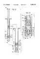
- FIG. 1is a partial cross-sectional view of first embodiment of the syringe system of the present invention showing the first and second containers before they are coupled together;
- FIG. 2is a greatly enlarged, fragmentary, cross-sectional view of the discharge end of the second container
- FIG. 3is a view of the components of FIG. 1 in an assembled condition with the seal in the first container penetrated by the piercing needle of the second container just prior to the second container being moved outwardly relative to the first container;
- FIG. 4is a view similar to FIG. 3, but FIG. 4 shows the second container moved outwardly relative to the first container to the maximum extent;
- FIG. 5is a greatly enlarged, fragmentary, cross-sectional view of the dispensing end of the first container shown with the first closure removed and replaced with a needle;
- FIG. 6is a cross-sectional view of a second embodiment of the present invention with the first and second containers separated prior to assembly;
- FIG. 7is a greatly enlarged, fragmentary, cross-sectional view of the seal of the first container of the second embodiment
- FIG. 8is a perspective view of the valve member employed in the second embodiment seal
- FIG. 9is a top plan view of the valve member shown in FIG. 8;
- FIG. 10is a view similar to FIG. 7, but FIG. 10 shows a modified seal of a third embodiment of the present invention.
- FIG. 10Ais a fragmentary, bottom plan view taken along the plane 10A--10A in FIG. 10;
- FIG. 11is a cross-sectional view of a fourth embodiment of the present invention showing the first and second containers separated prior to assembly.
- FIG. 12is a greatly enlarged, fragmentary, cross-sectional view of a portion of the assembled components of the fourth embodiment operated to open the mixing valve.
- FIGS. 1-5A first embodiment of the prefilled syringe system of the present invention is illustrated in FIGS. 1-5 and is designated generally therein by the reference number 20.
- the systemincludes a first container 22 defining a first chamber 24 and a dispensing end 26 defining a dispensing passage 28 communicating through the dispensing end 26 to accommodate the dispensing of fluid from the first chamber 24.
- the container 22may be fabricated from a synthetic polymer, such as a thermoplastic material.
- the dispensing end 26defines an exterior thread form 30 for receiving a threaded cap or first closure 32 and for subsequently receiving, upon removal of the closure 32, a hollow needle 34.
- Any other suitable conventional or special capping systemmay be employed.
- a first component or constituent 40is provided in the first container 22.
- the constituent 40in the preferred contemplated embodiment for use in medical applications, can be a drug or other medicament in granular form, powder form, or other particulate form. It may also be a liquid. It is contemplated that the constituent 20 in the container 22 would typically be a drug which, if in solid form, requires reconstitution, or if in liquid form, requires dilution. Thus, the system of the present invention will be useful in the containment of hazardous drugs such as are used in oncological applications or in biotechnology delivery applications.
- a movable seal 42is slidably disposed in the first chamber 24 above the first constituent 40.
- the sealis fabricated from a resilient, elastomeric material.
- the seal 42has an uncompressed diameter somewhat larger than the diameter of the chamber 24.
- a friction-fit engagementis established between the seal 42 and the chamber 24 that is sufficient to hold the seal 42 in place on top of the constituent 40 during normal packaging, shipping and handling.
- the force of engagementis sufficiently low to permit sliding of the seal 42 along the chamber 24 when the seal 42 is subjected to a sufficiently high axial force as described in detail hereinafter.
- an outer seal or cover 44over the upper, open end of the container 22. This prevents ingress of contaminants.
- the cover 44may be an adhesive backed, flexible web that can be readily pulled off just prior to use of the system.
- a second constituent 46in the form of a liquid, is sealed within a second container 48.
- the liquid constituent 46would typically be a diluent for diluting and/or reconstituting the first constituent 40.
- the second container 48may be formed from the same synthetic polymer materials as used for the first container 22.
- the second containerincludes a barrel 50 that is sized to be disposed in the first container 22 (FIGS. 3 and 4). Initially, in the pre-assembled condition, the second container 48 is preferably encased in a protective sleeve 52 which must be removed prior to use.
- the second container 48also includes a plunger 64 which is slidably disposed within the second container barrel 50.
- the plunger 64includes a piston 68 slidably received within the second container barrel 50.
- the piston 68is preferably initially located in contact with the liquid second constituent 46 at the upper end of the second container 48 as illustrated in FIG. 1.
- the plunger 64may be provided with a shank 70 having a threaded end or snap-fit end 72 for engaging a mating thread form or snap-fit form in the top of the piston 68.
- Such a structurepermits packaging of the system components with the plunger shank 70 not initially connected or assembled with the piston 68. When it is subsequently desired to use the system, the user can thread or snap-fit the shank 70 into the piston 68.
- the second container barrel 50has a discharge end 56 defining a discharge passage communicating through the discharge end to accommodate the discharge of fluid from the barrel 50.
- the second container barrel discharge passageis defined by the hollow interior of a piercing needle 60 which is mounted in the discharge end of the barrel 50.
- the second container 48is initially provided to the user with a second cap or closure mounted to the second container barrel discharge end over the piercing needle 60 as shown in FIG. 2.
- the second closure 62may be held on the discharge end of the second container by means of a snap-fit (or by other means, e.g., a threaded engagement (not illustrated) or the like).
- the operation of the packaging system syringe 10will next be described with reference to the sequential operational steps illustrated in FIGS. 3-5. The first stage of the operation is illustrated in FIG. 2.
- the second closure 62is removed to expose the piercing needle 60.
- the second container 48is inverted (so that the piercing needle 60 is pointing generally upwardly). This will ensure that the liquid constituent 46 cannot drip out. However, even if the second container 48 is not inverted, the liquid constituent 46 will not drip out. This is because the second container has no vent system that would admit ambient air into the second container 48 so as to permit the liquid constituent to flow out through the needle 60 solely under the influence of gravity. Absent such venting, the liquid constituent 46 remains in the second container 48 and is not able to flow out through the piercing needle 60.
- the first container 22is inverted and aligned with the second container 48. Then relative movement is effected so as to locate the distal end of the second container 48 in the first container 22. As illustrated in FIG. 3, the second container 48 is inserted into the first container 22 until the piercing needle 60 engages, and penetrates completely through, the first container seal 42.
- the plunger 64Before and during the step of inserting the second container 48 inside the first container 22, the plunger 64 is not moved relative to the second container 48.
- the plunger 64remains in the initial, outermost orientation.
- the plunger 64is pushed inwardly within the second container 48. This causes the liquid second constituent 46 to flow out through the hollow piercing needle 60 into the first constituent 40 within the first chamber 24.
- the hydraulic pressure within the first chamber 24acts on the second container seal 42 and the abutting distal end of the second container 48. This moves (i.e., pushes) the second container 48 outwardly relative to the first container 22.
- the ambient atmospheric pressurebears on the outside surface of the plunger piston 68, and this is effective in aiding the discharge of the liquid second constituent 46 into the first chamber 24.
- the top of the second container 48is adjacent the top of the plunger 64. Substantially all of the liquid second constituent has been discharged through the hollow piercing needle 60 into the first chamber 24 of the first container where it forms a solution with, mixes with, or is otherwise combined with the first constituent 40.
- the assemblycan be shaken to ensure good mixing.
- the first closure 32is removed from the first container 22, and the dispensing end 36 can be connected to the receiving component or discharge tubing (not illustrated).
- a hollow needle 34is mounted at the distal end of the first container dispensing end.
- the needle 34may be of a conventional, single-ended type with a straight, hollow, stainless steel shaft, typically 20 gauge in size.
- the needle 34may be provided with a swaged or molded hub 74 (FIG. 5) for engagement with the bottom, distal end of the first container dispensing end 36.
- the needle 34When properly mounted on the first container 22, the needle 34 is in alignment with the dispensing passage 28, and fluid communication is established between the dispensing passage 28 and the needle 34.
- the plunger 64 and container 48can be depressed by applying an axial force. This causes the combined constituents in the first chamber 24 to be dispensed or expelled from the chamber 24 through the needle 34.
- first container seal 42 and the second container piercing needle 60cooperatively define a connection means or coupling which accommodates the flow of the liquid second constituent from the second container into the first chamber of the first container.
- This connection or couplingaccommodates the movement of the seal 42 together with the second container 48-first outwardly to move (i.e., push or draw) the liquid second constituent 46 into the first chamber, and subsequently inwardly into the first chamber to dispense the combined constituents.
- FIG. 6-9An alternate embodiment of the syringe system of the present invention is illustrated in FIG. 6-9. Elements in the alternate embodiment which are the same as, or which function in an analogous manner to, elements of the first embodiment illustrated in FIGS. 1-5 are designated with three digit reference numbers wherein the last two digits are the same as the two digits of the reference number of the corresponding element in the first embodiment.
- the second embodiment of the syringe systemincludes a first container 122 and a second container 148.
- the first container 122has an open upper end which is initially sealed with a removable cover 144.
- the first container 122defines a first chamber 124 which contains a first constituent 140.
- the first constituent 140is deposited in the bottom of the first container 122 which defines a dispensing end 126 having a dispensing passage 128 communicating through the dispensing end 126 to accommodate the dispensing of fluid from the first chamber 124.
- a first removable closure 132is provided on the dispensing end 126.
- Suitable conventional or special cap retention systemsmay be provided, such as the mating thread forms as illustrated, snap-fit beads and grooves, etc.
- a movable seal 142is slidably disposed in the first chamber 124.
- the seal 142is retained with sufficient frictional engagement to prevent its movement within the first container 122 during normal storage, transport, and handling.
- a novel conduit assembly 176is mounted in the seal 142.
- the conduit assembly 176includes a generally elongate conduit 177 extending through the seal 142 and defining an internal flow passage 178 having an inlet 177A and an outlet 177B.
- the conduit assembly 176includes a laterally projecting boss 180 defining a receiving cavity 181 for receiving a ribbed anchor portion 184 of a valve member insert 185.
- the valve member insert 185includes a transversely oriented, resilient, spring member 186 extending from the lower end of the anchor portion 184.
- a frusto-conical valve member 187projects upwardly from the spring member 186.
- the exterior surface of the valve member 187is adapted to seal against the conduit outlet 177B.
- the spring member 186normally biases the valve member 187 in tight sealing engagement against the conduit outlet end 177B as illustrated in FIG. 7. This defines a one-way valve.
- the inlet end of the conduit assembly 176includes a connector or flange 179 or male thread form, such as is employed in connection systems marketed under the trademark LUER-LOK. This accommodates connection to the second container 148 as described in detail hereinafter. Other suitable conventional or special connecting systems may be employed.
- the second container 148is preferably initially provided with a surrounding, protective sleeve 152 which is removed and discarded subsequent to use.
- the second container 148has a barrel 150 containing a liquid second constituent 146 that is retained within the barrel 150 by a plunger 164 which has a piston 168 slidably disposed within the barrel 150.
- the bottom end of the second container 148defines a discharge end 156.
- the end 156includes an outwardly projecting discharge conduit 158 defining an internal discharge passage 159 communicating through the discharge end 156 to accommodate the discharge of fluid from the barrel 150 of the second container 148.
- a collar 161is spaced from, and surrounds, the discharge conduit 158.
- the collar 161defines an internal thread form, and this may be of the type that is employed in connection systems marketed under the trademark LUER-LOK.
- the collar 161can be threadingly engaged with the thread form or flange 179 at the inlet end of the connector assembly 176 projecting from the seal 142 in the first container 122.
- the second container projecting conduit 158is adapted to enter into the inlet 177A of the conduit assembly 176 and form a leak-tight seal with the conduit 177.
- the second container collar 161 and conduit 158thus function as a cooperating connector for connecting the second container 148 to the seal conduit assembly 176.
- Other suitable connection structurescould be used in place of the specific form of the collar 161, conduit 158, and conduit assembly flange 179 illustrated.
- a secondary, removable closure member 162in the form of a threaded plug, is threadingly engaged with the collar 161, and it must be removed prior to use. This prevents ingress of contaminants and insures that the liquid second constituent will not leak out of the second container 148.
- the removable closure 162is not employed, the liquid second constituent 146 cannot leak out of a small diameter passage 159 because there is no vent system that would admit ambient air into the second container 148 so as to permit the liquid constituent 146 to flow out solely under the influence of gravity.
- both containersare preferably held in an inverted position as the second container 148 is inserted into the first container 122 to connect the second container discharge conduit 158 with the first container conduit assembly 176.
- connection processis completed by inserting the second container 148 (with the closure 162 removed) to engage the collar 161 with the flange 179. Then relative rotation between the two containers is effected to complete the threaded engagement.
- first 122 and second 148 containersare moved (i.e., pulled) outwardly relative to each other.
- the seal 142is pulled outwardly, the volume beneath the seal 142 within the first chamber 124 increases and thus lowers the pressure therein. This results in a pressure differential which opens the valve member 187 as the liquid second constituent 146 flows into the first container 122 to combine with the first constituent 140.
- Ambient air pressure acting on the exterior surface of the plunger piston 168is transferred to the liquid second constituent 146.
- the two containersare pulled outwardly until the bottom interior surface of the plunger piston 168 engages the bottom, interior surface of the second container 148. At this point, all of the liquid second constituent 146 has been expelled from the barrel 150 of the second container 148 into the first container 122.
- the assemblycan be shaken to ensure good mixing.
- the first closure 132can then be removed from the first container 122, and the dispensing end 126 can be connected to a suitable receiving component or discharge tubing (not illustrated).
- a needlesuch as the needle 34 illustrated for the first embodiment in FIG. 5, may be attached to the first container 122.
- the plunger 164 and second container 148can be pushed inwardly to move the seal 142 inwardly further into the first container 122. This expels the combined constituents 140 and 146 from the first container 122.
- first container conduit assembly 176 and the second container conduit 158cooperatively define a coupling or flow-accommodating connection means which permits the liquid second constituent 146 to flow from the second container 148 into the first container 122.
- This couplingalso accommodates the outward movement of the containers 148 and 122 during the transfer of the liquid second constituent from the second container to the first container. Additionally, this coupling accommodates the subsequent inward movement of the containers during the dispensing of the combined constituents from the first container 122.
- FIGS. 10 and 10AA third embodiment of the present invention, which includes a modified form of the conduit connector, is illustrated in FIGS. 10 and 10A.
- This embodimentincludes a first container 222 defining a first chamber 24 in which a seal 242 is slidably disposed above a first constituent (not visible in FIGS. 10 and 10A).
- a conduit 277is mounted in the seal 242 and extends through the seal 242.
- the conduit 277defines an internal passage 78 and has an inlet 277A and an outlet 277B.
- the conduit 277includes a thread form or flange 279 which may be identical to the flange 179 described above with reference to the embodiment illustrated in FIGS. 6-9.
- the bottom of the seal 242has a frusto-conical shape 243 with a partial slit 289 oriented transversely to the axis of the frusto-conical shape at a outlet 277B of the conduit 277.
- the portion 290is resilient and normally biases the valve member 287 upwardly against the outlet 277B of the conduit 277 to occlude the passage 278.
- the seal 242 and conduit 277 illustrated in FIGS. 10 and 10Aare adapted to cooperate with a second container (not illustrated) that can be identical to the second container 148 described above with reference to the second embodiment illustrated in FIG. 6.
- the second containercan be inserted into the first container 222 and connected to the conduit 277 in the same manner as described above for the connection of the embodiment of the second container 148 with the first container 122 illustrated in FIG. 6.
- the operation of the embodiment of the system illustrated in FIGS. 10 and 10A with respect to combining the two constituents and subsequently dispensing themis identical with the operation of the second embodiment described above with reference to FIGS. 6-9.
- FIGS. 11 and 12A fourth embodiment, incorporating a presently preferred design, is illustrated in FIGS. 11 and 12.
- a number of the elements of the fourth embodiment of the syringe systemare identical or functionally analogous to corresponding elements in the first embodiment illustrated in FIGS. 15.
- the elements of the fourth embodiment illustrated in FIGS. 11 and 12are designated by three digit reference numbers.
- the last two digits of the fourth embodiment reference numbers for elements corresponding to elements in the first embodimentare identical to the two digit reference numbers used to designate those corresponding elements in the first three embodiments.
- the preferred form of the syringe systemincludes a first container 322 which has a first chamber 324 containing a first constituent 340.
- the lower portion of the first container 322includes a dispensing end 326 defining a dispensing passage 328.
- the dispensing passage 328is occluded with a first, removable closure 332 which may be held in a friction fit on the dispensing end 326.
- Other connection systemsmay be employed, such as snap-fit beads and grooves, threads, etc.
- a moveable seal 342is provided above the first constituent 340 in the first chamber 324.
- the seal 342has a lower end surface defining a conical shape 343.
- the apex of the conehas at least one slit or preferably two intersecting slits 389 (one of which is visible in FIG. 11).
- the single slitdefines two flaps and the intersecting slits define four flaps 387 which are normally biased to a closed position as illustrated in FIG. 11.
- the upper end surface of the sealhas an enlarged receiving cavity 393 and a smaller entrance passage 394 which together define a retention shoulder 395.
- the seal 342is initially installed in the first container 322 in a frictional engagement sufficient to prevent movement of the seal 342 during transport, storage, and handling.
- the sealis adapted to be engaged and moved with a second container 348 which includes a barrel 350 sized to be disposed in the first container 322.
- the barrel 350has a discharge end 356 defining a discharge passage 359 communicating through the discharge end 356 to accommodate the discharge of fluid from the barrel 350.
- the dispensing end 356has an enlarged head 396 and a smaller neck 398 (FIG. 11). The neck 398 and head 396 together define a transverse shoulder 399.
- a liquid second constituent 346is contained within the barrel 350 below a plunger 364 which has a piston 368.
- a suitable closure 362is removably mounted to the dispensing end 356.
- the closure 362may be held on the dispensing end 356 by means of a friction fit or by other suitable conventional or special means, such as threads, snap-fit beads and grooves, etc.
- a protective sleeve(not illustrated) may be provided for surrounding the barrel 350 in substantially the same manner that the sleeve 52 surrounds the barrel 50 of the second container of the first embodiment illustrated in FIG. 1.
- the first container 322may include a removable cover (not illustrated), such as the cover 44 shown on the top of the first container 22 of the first embodiment illustrated in FIG. 1.
- the cap 362is removed from the second container 348.
- the second container 348is then disposed within the first container 322.
- this stepis accomplished by first inverting the second container 348 before the closure 362 is removed.
- the first container 322is also inverted, and the two containers are telescopically engaged in the inverted position.
- the second container 348is pushed into the first container 322 until the second container head 396 sufficiently expands the seal entrance passage 394 and enters into the seal receiving cavity 393.
- the seal flaps or valve members 387remain closed so as to ensure that there will be no leakage of the liquid second constituent into the first constituent 340.
- the first and second containersare pulled outwardly relative to each other.
- Ambient air pressure acting on the plunger 368results in the liquid second constituent 346 being maintained at ambient atmospheric pressure.
- the increasing volume of the first chamber 324 under the seal 342creates a negative pressure differential, and the liquid second constituent 346 forces the valve members 387 outwardly to the open position illustrated in FIG. 12.
- the liquid second constituent 346can thus flow into the first constituent 340.
- the two containersare pulled outwardly relative to each other until the bottom surface of the plunger piston 368 engages the bottom of the second container barrel 350. At this point, all of the liquid second constituent 346 has been expelled into the first constituent 340 in the first chamber 324.
- the valve flaps 387then close. The assembly can then be shaken to ensure good mixing.
- the closure 332is removed from the first container dispensing end 326.
- the first container dispensing end 326can then be connected to a receiving component or discharge tubing (not illustrated) or to a needle (such as the needle 34 described above with reference to the first embodiment illustrated in FIGS. 1-5).
- the plunger 364is pushed inwardly. This urges the plunger piston 368 against the bottom of the second container barrel 350 to move the second container and connected seal 342 toward the bottom of the first container 322. This results in the combined constituents being dispensed from the first container 322.
- the dispensing ends of the first containersare sealed with removable closures (such as the first container dispensing end closure 32.)
- the second container dispensing endmay include a closures (i.e., closure 62 illustrated in FIG. 1). Further, such closures, if employed, may be provided in alternate forms such as threadable elastomeric seal members, flexible adhesive seal members, shrink wrap films, or other closure systems.
- an inwardly directed forcemay be applied to the plunger 364 to assist in transferring the second liquid constituent from the second container to the first container.
- the above-described syringe system of the present inventionprovides an advantageous means for dispensing a combination of two constituents that must be kept separate from each other until they are to be used in combination.
- the systemis self-contained and sealed. Reconstitution or dilution of a drug using this system can be effected at bedside when the drug is needed.
- the choice of the diluent liquidis not restricted or limited because the system accommodates any diluent compatible with the structural materials employed.
- the systempermits the constituents to be stored in forms in which the stability of the components is maximized. Because the reconstituted product is used immediately, provisions do not have to be made for refrigeration or other storage procedures which might otherwise be required for certain types of reconstituted products.
Landscapes
- Health & Medical Sciences (AREA)
- Vascular Medicine (AREA)
- Engineering & Computer Science (AREA)
- Anesthesiology (AREA)
- Biomedical Technology (AREA)
- Heart & Thoracic Surgery (AREA)
- Hematology (AREA)
- Life Sciences & Earth Sciences (AREA)
- Animal Behavior & Ethology (AREA)
- General Health & Medical Sciences (AREA)
- Public Health (AREA)
- Veterinary Medicine (AREA)
- Medical Preparation Storing Or Oral Administration Devices (AREA)
Abstract
Description
This invention relates to a packaging system and dispensing system for two constituents or components that are stored separately in isolation from each other but which must be combined or mixed together prior to dispensing. The invention is particularly suitable for use with a medicament, such as a drug in powder form, which must be dissolved and diluted in a liquid.
In some medical applications, as well as in some industrial or other applications, it is necessary, or at least preferable, to maintain two components or constituents in isolation prior to combining the two components for subsequent dispensing as a solution, mixture, or other combination.
For example, some pharmaceutical preparations, such as injectable solutions or suspensions of a drug, are not sufficiently stable to accommodate prolonged storage prior to use. However, the components of the solution or suspension may have adequate stability if the components are stored separately prior to being combined.
It would be desirable to provide an improved system that will accommodate the packaging of two such components in isolation from each other, but which can be subsequently operated to combine or mix the components for dispensing. In particular, it would be advantageous to provide such an improved system with the capability, where necessary, for employing component containers that can be manufactured and/or stored separately as well as together.
It would be especially advantageous if such an improved system could be employed with two liquid components as well as with at least one solid component.
It would be desirable with such a system to positively seal both components from the ambient atmosphere as well as from each other.
It would also be beneficial if such an improved system could be provided in a self-contained form that is compact, portable, simple to manipulate, and readily adaptable to different proportions and dosages of the components.
Additionally, it would be desirable if such an improved system could readily accommodate the storage and administration of a variety of drugs which require reconstitution and/or dilution including, among other types, a medicament in powder form requiring mixing with a diluent, a medicament in liquid form requiring mixing with a diluent, and a lyophilized compound requiring mixing with a diluent.
The present invention provides an improved packaging and dispensing system which can accommodate designs having the above-discussed benefits and features.
The present invention provides a syringe system for storing two components or constituents in isolation from each other. The system can be subsequently operated for combining or mixing the two constituents and for then dispensing the combination.
The syringe system includes first and second containers. The first container includes a first chamber which has a dispensing end.
The dispensing end defines a dispensing passage communicating through the dispensing end to accommodate the dispensing of fluid from the first chamber. Preferably, a first removable closure is provided to occlude the dispensing passage.
A moveable seal is slidably disposed in the first chamber. The first chamber is preferably prefilled with a first constituent between the seal and the dispensing end.
The second container includes a barrel that is sized to be disposed in the first container and that has a discharge end defining a discharge passage communicating through the discharge end to accommodate the discharge of fluid front the barrel. Preferably, a second removable closure is provided to occlude the discharge passage.
A plunger is slidably disposed within the barrel. The second container is preferably prefilled with a liquid second constituent in the barrel between the discharge end and the plunger.
In order to combine the two constituents, the second closure, if any, is first removed from the barrel discharge end. The first container seal and the second container barrel discharge end are engageable to cooperatively define a coupling accommodating the flow of the liquid second constituent front the barrel into the first chamber as the second container and seal move outwardly relative to the first chamber. The liquid constituent is then moved (i.e., pushed or drawn) from the second container into the first container where the liquid second constituent mixes with the first constituent. The assembly may be shaken to promote mixing.
Subsequently, the first closure can be removed from the first container. Then the plunger, which is now engaged with the raised bottom of the second container, can be pushed inwardly. This carries both the second container and coupled seal further inwardly into the first chamber. This dispenses the mixed contents of the first chamber through the dispensing passage.
Numerous other advantages and features of the present invention will become readily apparent from the following detailed description of the invention, from the claims, and from the accompanying drawings.
In the accompanying drawings that form part of the specification, and in which like numerals are employed to designate like parts throughout the same,
FIG. 1 is a partial cross-sectional view of first embodiment of the syringe system of the present invention showing the first and second containers before they are coupled together;
FIG. 2 is a greatly enlarged, fragmentary, cross-sectional view of the discharge end of the second container;
FIG. 3 is a view of the components of FIG. 1 in an assembled condition with the seal in the first container penetrated by the piercing needle of the second container just prior to the second container being moved outwardly relative to the first container;
FIG. 4 is a view similar to FIG. 3, but FIG. 4 shows the second container moved outwardly relative to the first container to the maximum extent;
FIG. 5 is a greatly enlarged, fragmentary, cross-sectional view of the dispensing end of the first container shown with the first closure removed and replaced with a needle;
FIG. 6 is a cross-sectional view of a second embodiment of the present invention with the first and second containers separated prior to assembly;
FIG. 7 is a greatly enlarged, fragmentary, cross-sectional view of the seal of the first container of the second embodiment;
FIG. 8 is a perspective view of the valve member employed in the second embodiment seal;
FIG. 9 is a top plan view of the valve member shown in FIG. 8;
FIG. 10 is a view similar to FIG. 7, but FIG. 10 shows a modified seal of a third embodiment of the present invention;
FIG. 10A is a fragmentary, bottom plan view taken along theplane 10A--10A in FIG. 10;
FIG. 11 is a cross-sectional view of a fourth embodiment of the present invention showing the first and second containers separated prior to assembly; and
FIG. 12 is a greatly enlarged, fragmentary, cross-sectional view of a portion of the assembled components of the fourth embodiment operated to open the mixing valve.
While this invention is susceptible of embodiment in many different forms, this specification and the accompanying drawings disclose only some specific forms as examples of the invention. The invention is not intended to be limited to the embodiments so described, however. The scope of the invention is pointed out in the appended claims.
Figures illustrating the apparatus show some mechanical elements that are known and that will be recognized by one skilled in the art. The detailed descriptions of such elements are not necessary to an understanding of the invention, and accordingly, are herein presented only to the degree necessary to facilitate an understanding of the novel features of the present invention.
A first embodiment of the prefilled syringe system of the present invention is illustrated in FIGS. 1-5 and is designated generally therein by thereference number 20. The system includes afirst container 22 defining afirst chamber 24 and a dispensingend 26 defining a dispensingpassage 28 communicating through the dispensingend 26 to accommodate the dispensing of fluid from thefirst chamber 24. It is presently contemplated that in the preferred embodiment thecontainer 22 may be fabricated from a synthetic polymer, such as a thermoplastic material.
Preferably, the dispensingend 26 defines anexterior thread form 30 for receiving a threaded cap orfirst closure 32 and for subsequently receiving, upon removal of theclosure 32, ahollow needle 34. Any other suitable conventional or special capping system may be employed.
A first component orconstituent 40 is provided in thefirst container 22. Theconstituent 40, in the preferred contemplated embodiment for use in medical applications, can be a drug or other medicament in granular form, powder form, or other particulate form. It may also be a liquid. It is contemplated that the constituent 20 in thecontainer 22 would typically be a drug which, if in solid form, requires reconstitution, or if in liquid form, requires dilution. Thus, the system of the present invention will be useful in the containment of hazardous drugs such as are used in oncological applications or in biotechnology delivery applications.
Amovable seal 42 is slidably disposed in thefirst chamber 24 above thefirst constituent 40. Preferably, the seal is fabricated from a resilient, elastomeric material. In the preferred form, theseal 42 has an uncompressed diameter somewhat larger than the diameter of thechamber 24. A friction-fit engagement is established between theseal 42 and thechamber 24 that is sufficient to hold theseal 42 in place on top of the constituent 40 during normal packaging, shipping and handling. However, the force of engagement is sufficiently low to permit sliding of theseal 42 along thechamber 24 when theseal 42 is subjected to a sufficiently high axial force as described in detail hereinafter.
Also, as illustrated in FIG. 1, it is preferred to provide an outer seal or cover 44 over the upper, open end of thecontainer 22. This prevents ingress of contaminants. Thecover 44 may be an adhesive backed, flexible web that can be readily pulled off just prior to use of the system.
Asecond constituent 46, in the form of a liquid, is sealed within asecond container 48. The liquid constituent 46 would typically be a diluent for diluting and/or reconstituting thefirst constituent 40. Thesecond container 48 may be formed from the same synthetic polymer materials as used for thefirst container 22.
The second container includes abarrel 50 that is sized to be disposed in the first container 22 (FIGS. 3 and 4). Initially, in the pre-assembled condition, thesecond container 48 is preferably encased in aprotective sleeve 52 which must be removed prior to use. Thesecond container 48 also includes aplunger 64 which is slidably disposed within thesecond container barrel 50. Theplunger 64 includes apiston 68 slidably received within thesecond container barrel 50.
Thepiston 68 is preferably initially located in contact with the liquid second constituent 46 at the upper end of thesecond container 48 as illustrated in FIG. 1. For packaging convenience, theplunger 64 may be provided with ashank 70 having a threaded end or snap-fit end 72 for engaging a mating thread form or snap-fit form in the top of thepiston 68. Such a structure permits packaging of the system components with theplunger shank 70 not initially connected or assembled with thepiston 68. When it is subsequently desired to use the system, the user can thread or snap-fit theshank 70 into thepiston 68.
Thesecond container barrel 50 has adischarge end 56 defining a discharge passage communicating through the discharge end to accommodate the discharge of fluid from thebarrel 50. In the first embodiment illustrated in FIGS. 1-5, the second container barrel discharge passage is defined by the hollow interior of a piercingneedle 60 which is mounted in the discharge end of thebarrel 50.
Preferably, thesecond container 48 is initially provided to the user with a second cap or closure mounted to the second container barrel discharge end over the piercingneedle 60 as shown in FIG. 2. Thesecond closure 62 may be held on the discharge end of the second container by means of a snap-fit (or by other means, e.g., a threaded engagement (not illustrated) or the like). The operation of the packaging system syringe 10 will next be described with reference to the sequential operational steps illustrated in FIGS. 3-5. The first stage of the operation is illustrated in FIG. 2.
Just prior to use, thesecond closure 62 is removed to expose the piercingneedle 60. Preferably, before thesecond closure 62 is removed, thesecond container 48 is inverted (so that the piercingneedle 60 is pointing generally upwardly). This will ensure that the liquid constituent 46 cannot drip out. However, even if thesecond container 48 is not inverted, the liquid constituent 46 will not drip out. This is because the second container has no vent system that would admit ambient air into thesecond container 48 so as to permit the liquid constituent to flow out through theneedle 60 solely under the influence of gravity. Absent such venting, the liquid constituent 46 remains in thesecond container 48 and is not able to flow out through the piercingneedle 60.
With thesecond container 48 preferably inverted to point the piercingneedle 60 upwardly, thefirst container 22 is inverted and aligned with thesecond container 48. Then relative movement is effected so as to locate the distal end of thesecond container 48 in thefirst container 22. As illustrated in FIG. 3, thesecond container 48 is inserted into thefirst container 22 until the piercingneedle 60 engages, and penetrates completely through, thefirst container seal 42.
Before and during the step of inserting thesecond container 48 inside thefirst container 22, theplunger 64 is not moved relative to thesecond container 48. Theplunger 64 remains in the initial, outermost orientation. After the two containers are telescopically disposed with the piercingneedle 60 fully penetrating thesecond container seal 42, theplunger 64 is pushed inwardly within thesecond container 48. This causes the liquid second constituent 46 to flow out through the hollow piercingneedle 60 into thefirst constituent 40 within thefirst chamber 24. The hydraulic pressure within thefirst chamber 24 acts on thesecond container seal 42 and the abutting distal end of thesecond container 48. This moves (i.e., pushes) thesecond container 48 outwardly relative to thefirst container 22. It will be appreciated that the ambient atmospheric pressure bears on the outside surface of theplunger piston 68, and this is effective in aiding the discharge of the liquid second constituent 46 into thefirst chamber 24.
When thepiston 68 is seated at the bottom, discharge end of thesecond container 48, the top of thesecond container 48 is adjacent the top of theplunger 64. Substantially all of the liquid second constituent has been discharged through the hollow piercingneedle 60 into thefirst chamber 24 of the first container where it forms a solution with, mixes with, or is otherwise combined with thefirst constituent 40. The assembly can be shaken to ensure good mixing.
After the constituents are sufficiently mixed, thefirst closure 32 is removed from thefirst container 22, and the dispensing end 36 can be connected to the receiving component or discharge tubing (not illustrated). Typically, ahollow needle 34 is mounted at the distal end of the first container dispensing end. Theneedle 34 may be of a conventional, single-ended type with a straight, hollow, stainless steel shaft, typically 20 gauge in size. Theneedle 34 may be provided with a swaged or molded hub 74 (FIG. 5) for engagement with the bottom, distal end of the first container dispensing end 36.
When properly mounted on thefirst container 22, theneedle 34 is in alignment with the dispensingpassage 28, and fluid communication is established between the dispensingpassage 28 and theneedle 34. After theneedle 34 is properly mounted on thefirst container 22, (or after the first container is otherwise properly connected to some suitable receiving component), theplunger 64 andcontainer 48 can be depressed by applying an axial force. This causes the combined constituents in thefirst chamber 24 to be dispensed or expelled from thechamber 24 through theneedle 34.
It will be appreciated that the central portion of thefirst container seal 42 and the secondcontainer piercing needle 60 cooperatively define a connection means or coupling which accommodates the flow of the liquid second constituent from the second container into the first chamber of the first container. This connection or coupling accommodates the movement of theseal 42 together with the second container 48-first outwardly to move (i.e., push or draw) the liquid second constituent 46 into the first chamber, and subsequently inwardly into the first chamber to dispense the combined constituents.
An alternate embodiment of the syringe system of the present invention is illustrated in FIG. 6-9. Elements in the alternate embodiment which are the same as, or which function in an analogous manner to, elements of the first embodiment illustrated in FIGS. 1-5 are designated with three digit reference numbers wherein the last two digits are the same as the two digits of the reference number of the corresponding element in the first embodiment.
With reference to FIG. 6, the second embodiment of the syringe system includes afirst container 122 and asecond container 148. Thefirst container 122 has an open upper end which is initially sealed with aremovable cover 144. Thefirst container 122 defines afirst chamber 124 which contains afirst constituent 140. Thefirst constituent 140 is deposited in the bottom of thefirst container 122 which defines a dispensingend 126 having a dispensingpassage 128 communicating through the dispensingend 126 to accommodate the dispensing of fluid from thefirst chamber 124. Normally, a firstremovable closure 132 is provided on the dispensingend 126. Suitable conventional or special cap retention systems may be provided, such as the mating thread forms as illustrated, snap-fit beads and grooves, etc.
Amovable seal 142 is slidably disposed in thefirst chamber 124. Theseal 142 is retained with sufficient frictional engagement to prevent its movement within thefirst container 122 during normal storage, transport, and handling.
As can be seen in FIG. 7, anovel conduit assembly 176 is mounted in theseal 142. Theconduit assembly 176 includes a generallyelongate conduit 177 extending through theseal 142 and defining aninternal flow passage 178 having aninlet 177A and anoutlet 177B.
Theconduit assembly 176 includes a laterally projectingboss 180 defining a receivingcavity 181 for receiving aribbed anchor portion 184 of avalve member insert 185. Thevalve member insert 185 includes a transversely oriented, resilient,spring member 186 extending from the lower end of theanchor portion 184. A frusto-conical valve member 187 projects upwardly from thespring member 186. The exterior surface of thevalve member 187 is adapted to seal against theconduit outlet 177B. Thespring member 186 normally biases thevalve member 187 in tight sealing engagement against theconduit outlet end 177B as illustrated in FIG. 7. This defines a one-way valve.
The inlet end of theconduit assembly 176 includes a connector orflange 179 or male thread form, such as is employed in connection systems marketed under the trademark LUER-LOK. This accommodates connection to thesecond container 148 as described in detail hereinafter. Other suitable conventional or special connecting systems may be employed.
Thesecond container 148 is preferably initially provided with a surrounding,protective sleeve 152 which is removed and discarded subsequent to use.
Thesecond container 148 has abarrel 150 containing a liquidsecond constituent 146 that is retained within thebarrel 150 by aplunger 164 which has apiston 168 slidably disposed within thebarrel 150.
The bottom end of thesecond container 148 defines adischarge end 156. Theend 156 includes an outwardly projectingdischarge conduit 158 defining aninternal discharge passage 159 communicating through thedischarge end 156 to accommodate the discharge of fluid from thebarrel 150 of thesecond container 148.
Acollar 161 is spaced from, and surrounds, thedischarge conduit 158. Thecollar 161 defines an internal thread form, and this may be of the type that is employed in connection systems marketed under the trademark LUER-LOK. Thus, thecollar 161 can be threadingly engaged with the thread form orflange 179 at the inlet end of theconnector assembly 176 projecting from theseal 142 in thefirst container 122. The secondcontainer projecting conduit 158 is adapted to enter into theinlet 177A of theconduit assembly 176 and form a leak-tight seal with theconduit 177. Thesecond container collar 161 andconduit 158 thus function as a cooperating connector for connecting thesecond container 148 to theseal conduit assembly 176. Other suitable connection structures could be used in place of the specific form of thecollar 161,conduit 158, andconduit assembly flange 179 illustrated.
Preferably, a secondary,removable closure member 162, in the form of a threaded plug, is threadingly engaged with thecollar 161, and it must be removed prior to use. This prevents ingress of contaminants and insures that the liquid second constituent will not leak out of thesecond container 148. Of course, even if theremovable closure 162 is not employed, the liquidsecond constituent 146 cannot leak out of asmall diameter passage 159 because there is no vent system that would admit ambient air into thesecond container 148 so as to permit theliquid constituent 146 to flow out solely under the influence of gravity. Nevertheless, both containers are preferably held in an inverted position as thesecond container 148 is inserted into thefirst container 122 to connect the secondcontainer discharge conduit 158 with the firstcontainer conduit assembly 176.
The connection process is completed by inserting the second container 148 (with theclosure 162 removed) to engage thecollar 161 with theflange 179. Then relative rotation between the two containers is effected to complete the threaded engagement.
Subsequently, the first 122 and second 148 containers are moved (i.e., pulled) outwardly relative to each other. As theseal 142 is pulled outwardly, the volume beneath theseal 142 within thefirst chamber 124 increases and thus lowers the pressure therein. This results in a pressure differential which opens thevalve member 187 as the liquidsecond constituent 146 flows into thefirst container 122 to combine with thefirst constituent 140. Ambient air pressure acting on the exterior surface of theplunger piston 168 is transferred to the liquidsecond constituent 146.
The two containers are pulled outwardly until the bottom interior surface of theplunger piston 168 engages the bottom, interior surface of thesecond container 148. At this point, all of the liquidsecond constituent 146 has been expelled from thebarrel 150 of thesecond container 148 into thefirst container 122. The assembly can be shaken to ensure good mixing.
Thefirst closure 132 can then be removed from thefirst container 122, and the dispensingend 126 can be connected to a suitable receiving component or discharge tubing (not illustrated). Alternatively, a needle, such as theneedle 34 illustrated for the first embodiment in FIG. 5, may be attached to thefirst container 122.
Subsequently, theplunger 164 andsecond container 148 can be pushed inwardly to move theseal 142 inwardly further into thefirst container 122. This expels the combinedconstituents first container 122.
It will be appreciated that the firstcontainer conduit assembly 176 and thesecond container conduit 158 cooperatively define a coupling or flow-accommodating connection means which permits the liquidsecond constituent 146 to flow from thesecond container 148 into thefirst container 122. This coupling also accommodates the outward movement of thecontainers first container 122.
A third embodiment of the present invention, which includes a modified form of the conduit connector, is illustrated in FIGS. 10 and 10A. This embodiment includes afirst container 222 defining afirst chamber 24 in which aseal 242 is slidably disposed above a first constituent (not visible in FIGS. 10 and 10A). Aconduit 277 is mounted in theseal 242 and extends through theseal 242. Theconduit 277 defines an internal passage 78 and has aninlet 277A and anoutlet 277B. At theinlet 277A, theconduit 277 includes a thread form orflange 279 which may be identical to theflange 179 described above with reference to the embodiment illustrated in FIGS. 6-9.
The bottom of theseal 242 has a frusto-conical shape 243 with apartial slit 289 oriented transversely to the axis of the frusto-conical shape at aoutlet 277B of theconduit 277. This defines a flap orvalve member 287 which is attached with an unslit portion 290 (FIG. 10A) to the main body of theseal 242. Theportion 290 is resilient and normally biases thevalve member 287 upwardly against theoutlet 277B of theconduit 277 to occlude thepassage 278.
Theseal 242 andconduit 277 illustrated in FIGS. 10 and 10A are adapted to cooperate with a second container (not illustrated) that can be identical to thesecond container 148 described above with reference to the second embodiment illustrated in FIG. 6. The second container can be inserted into thefirst container 222 and connected to theconduit 277 in the same manner as described above for the connection of the embodiment of thesecond container 148 with thefirst container 122 illustrated in FIG. 6. The operation of the embodiment of the system illustrated in FIGS. 10 and 10A with respect to combining the two constituents and subsequently dispensing them is identical with the operation of the second embodiment described above with reference to FIGS. 6-9.
A fourth embodiment, incorporating a presently preferred design, is illustrated in FIGS. 11 and 12. A number of the elements of the fourth embodiment of the syringe system are identical or functionally analogous to corresponding elements in the first embodiment illustrated in FIGS. 15. The elements of the fourth embodiment illustrated in FIGS. 11 and 12 are designated by three digit reference numbers. The last two digits of the fourth embodiment reference numbers for elements corresponding to elements in the first embodiment are identical to the two digit reference numbers used to designate those corresponding elements in the first three embodiments.
With reference to FIG. 11, the preferred form of the syringe system includes afirst container 322 which has a first chamber 324 containing afirst constituent 340. The lower portion of thefirst container 322 includes a dispensingend 326 defining a dispensing passage 328. Preferably, the dispensing passage 328 is occluded with a first,removable closure 332 which may be held in a friction fit on the dispensingend 326. Other connection systems may be employed, such as snap-fit beads and grooves, threads, etc.
Amoveable seal 342 is provided above thefirst constituent 340 in the first chamber 324. Theseal 342 has a lower end surface defining aconical shape 343. The apex of the cone has at least one slit or preferably two intersecting slits 389 (one of which is visible in FIG. 11). The single slit defines two flaps and the intersecting slits define fourflaps 387 which are normally biased to a closed position as illustrated in FIG. 11. The upper end surface of the seal has an enlarged receivingcavity 393 and asmaller entrance passage 394 which together define aretention shoulder 395.
Theseal 342 is initially installed in thefirst container 322 in a frictional engagement sufficient to prevent movement of theseal 342 during transport, storage, and handling. The seal is adapted to be engaged and moved with asecond container 348 which includes abarrel 350 sized to be disposed in thefirst container 322.
Thebarrel 350 has adischarge end 356 defining adischarge passage 359 communicating through thedischarge end 356 to accommodate the discharge of fluid from thebarrel 350. The dispensingend 356 has anenlarged head 396 and a smaller neck 398 (FIG. 11). Theneck 398 andhead 396 together define atransverse shoulder 399.
A liquidsecond constituent 346 is contained within thebarrel 350 below aplunger 364 which has apiston 368. Preferably, in order to minimize the likelihood of contaminant ingress and to minimize the likelihood of leakage of the constituent 346, asuitable closure 362 is removably mounted to the dispensingend 356. Theclosure 362 may be held on the dispensingend 356 by means of a friction fit or by other suitable conventional or special means, such as threads, snap-fit beads and grooves, etc.
Preferably, a protective sleeve (not illustrated) may be provided for surrounding thebarrel 350 in substantially the same manner that thesleeve 52 surrounds thebarrel 50 of the second container of the first embodiment illustrated in FIG. 1.
Also, if desired, thefirst container 322 may include a removable cover (not illustrated), such as thecover 44 shown on the top of thefirst container 22 of the first embodiment illustrated in FIG. 1.
In order to use the system illustrated in FIGS. 11 and 12, thecap 362 is removed from thesecond container 348. Thesecond container 348 is then disposed within thefirst container 322. Preferably, this step is accomplished by first inverting thesecond container 348 before theclosure 362 is removed. Thefirst container 322 is also inverted, and the two containers are telescopically engaged in the inverted position. Thesecond container 348 is pushed into thefirst container 322 until thesecond container head 396 sufficiently expands theseal entrance passage 394 and enters into theseal receiving cavity 393. In this position, the second container dispensingend neck 398 is received in thesmaller entrance passage 394 which, owing to the resiliency of theseal 342, has assumed its smaller diameter configuration whereby theseal retaining flange 395 engages thesecond container flange 399. This prevents separation of thesecond container 348 from thefirst container seal 342.
In the initially engaged position, wherein the secondcontainer dispensing end 356 is connected to thefirst container seal 342, the seal flaps orvalve members 387 remain closed so as to ensure that there will be no leakage of the liquid second constituent into thefirst constituent 340.
Subsequently, the first and second containers are pulled outwardly relative to each other. Ambient air pressure acting on theplunger 368 results in the liquidsecond constituent 346 being maintained at ambient atmospheric pressure. The increasing volume of the first chamber 324 under theseal 342 creates a negative pressure differential, and the liquidsecond constituent 346 forces thevalve members 387 outwardly to the open position illustrated in FIG. 12. The liquidsecond constituent 346 can thus flow into thefirst constituent 340.
The two containers are pulled outwardly relative to each other until the bottom surface of theplunger piston 368 engages the bottom of thesecond container barrel 350. At this point, all of the liquidsecond constituent 346 has been expelled into thefirst constituent 340 in the first chamber 324. The valve flaps 387 then close. The assembly can then be shaken to ensure good mixing.
Subsequently, theclosure 332 is removed from the firstcontainer dispensing end 326. The firstcontainer dispensing end 326 can then be connected to a receiving component or discharge tubing (not illustrated) or to a needle (such as theneedle 34 described above with reference to the first embodiment illustrated in FIGS. 1-5). Then theplunger 364 is pushed inwardly. This urges theplunger piston 368 against the bottom of thesecond container barrel 350 to move the second container andconnected seal 342 toward the bottom of thefirst container 322. This results in the combined constituents being dispensed from thefirst container 322.
It will be appreciated that, in all of the embodiments illustrated, the dispensing ends of the first containers are sealed with removable closures (such as the first container dispensingend closure 32.) The second container dispensing end may include a closures (i.e.,closure 62 illustrated in FIG. 1). Further, such closures, if employed, may be provided in alternate forms such as threadable elastomeric seal members, flexible adhesive seal members, shrink wrap films, or other closure systems.
Further, after the first and second containers have been initially coupled together and as the containers are subsequently moved (i.e., pushed or pulled) outwardly relative to each other, an inwardly directed force may be applied to theplunger 364 to assist in transferring the second liquid constituent from the second container to the first container.
The above-described syringe system of the present invention provides an advantageous means for dispensing a combination of two constituents that must be kept separate from each other until they are to be used in combination. The system is self-contained and sealed. Reconstitution or dilution of a drug using this system can be effected at bedside when the drug is needed. The choice of the diluent liquid is not restricted or limited because the system accommodates any diluent compatible with the structural materials employed.
The system permits the constituents to be stored in forms in which the stability of the components is maximized. Because the reconstituted product is used immediately, provisions do not have to be made for refrigeration or other storage procedures which might otherwise be required for certain types of reconstituted products.
It will be readily apparent from the foregoing detailed description of the invention and from the illustrations thereof that numerous variations and modifications may be effected without departing from the true spirit and scope of the novel concepts or principles of this invention.
Claims (18)
1. A syringe system comprising:
a first container including
a first chamber having a dispensing end defining a dispensing passage communicating through said dispensing end to accommodate the dispensing of fluid from said first chamber,
a movable seal slidably disposed in said first chamber, and
a first constituent in said first chamber between said dispensing end and said seal;
a second container including
a barrel that is sized to be disposed in said first container and that has a discharge end defining a discharge passage communicating through said discharge end to accommodate the discharge of fluid from said barrel,
a plunger slidably disposed within said barrel, and
a liquid second constituent in said barrel between said discharge end and said plunger; and
said first container seal and said second container barrel discharge end being engageable to cooperatively define a coupling accommodating the flow of said liquid second constituent from said barrel into said first chamber as said second container and seal move outwardly relative to said first chamber,
wherein said coupling includes:
(1) said seal is resilient and has at least one slit defining flaps which are biased to a normally closed position and which can open on the downstream side into said first chamber,
(2) an enlarged receiving cavity in said seal adjacent an upstream side of said flaps and a smaller entrance passage in said seal opening to said cavity whereby a retention shoulder is defined at one end of said cavity around said smaller entrance passage, and
(3) an enlarged head at said second container barrel discharge end for being received in said seal enlarged receiving cavity and a smaller neck at said second container barrel discharge end for being received in said seal entrance passage whereby said second container barrel discharge passage is normally occluded by said seal flaps in the biased closed position.
2. The system in accordance with claim 1 in which said plunger includes a piston and a shank removably mounted in said piston.
3. The system in accordance with claim 1 in which said coupling includes:
(1) a hollow piercing needle carried at said barrel discharge end in communication with said discharge passage, and
(2) a portion of said seal being fully penetratable by said piercing needle.
4. The system in accordance with claim 1 in which said coupling includes:
(1) a conduit extending through said seal and having inlet and outlet ends,
(2) a flapper valve member in said seal adjacent said conduit outlet end and biased to a normally closed position occluding said conduit outlet end,
(3) a flange on said conduit inlet end, and
(4) a thread form on said second container barrel discharge end for threadingly engaging said flange whereby communication is established between said discharge end and said conduit.
5. The system in accordance with claim 1 further including
a first removable closure occluding said dispensing passage;
a second removable closure occluding said barrel discharge passage; and
a cover removably mounted to said first container opposite said dispensing end.
6. The system in accordance with claim 1 further including a hollow needle mounted on said dispensing end of said first container in communication with said dispensing passage.
7. The system in accordance with claim 1 further including a protective sleeve for receiving said second container in a storage mode.
8. The system in accordance with claim 1 in which said seal is a resilient elastomeric material.
9. A prefilled syringe system for separately storing a first constituent and a liquid second constituent and for subsequently mixing and dispensing a mixture of said constituents, said system comprising:
a first container including
a first chamber having a dispensing end defining a dispensing passage communicating through said dispensing end to accommodate the dispensing of fluid from said first chamber,
a first removable closure sealingly occluding said dispensing passage,
a movable seal slidably disposed in said first chamber, and
a first constituent in said first chamber between said dispensing end and said seal;
a second container including
a barrel that is sized to be disposed in said first container and that has a discharge end defining a discharge passage communicating through said discharge end to accommodate the discharge of fluid from said barrel,
a second removable closure occluding said barrel discharge passage,
a plunger slidably disposed within said barrel, and
a liquid second constituent in said barrel between said discharge end and said plunger; and
said first container seal and said second container barrel discharge end being engageable upon removal of said second closure to cooperatively define a coupling accommodating the flow of said liquid second constituent from said barrel into said first chamber as said second container and seal move outwardly relative to said first chamber, and said plunger being axially engageable with said barrel to move said barrel and seal inwardly relative to said first chamber to expel the combined contents of said first chamber,
wherein said coupling includes:
(1) said seal is resilient and has at least one slit defining flaps which are biased to a normally closed position and which can open on the downstream side into said first chamber,
(2) an enlarged receiving cavity in said seal adjacent an upstream side of said flaps and a smaller entrance passage in said seal opening to said cavity whereby a retention shoulder is defined at one end of said cavity around said smaller entrance passage, and
(3) an enlarged head at said second container barrel discharge end for being received in said seal enlarged receiving cavity upon removal of said second closure and a smaller neck at said second container barrel discharge end for being received in said seal entrance passage whereby said second container barrel discharge passage is normally occluded by said seal flaps in the biased closed position.
10. The system in accordance with claim 9 in which said plunger includes a piston and a shank removably mounted in said piston.
11. The system in accordance with claim 9 in which said coupling includes:
(1) a hollow piercing needle carried at said barrel discharge end in communication with said discharge passage, and
(2) a portion of said seal being fully penetratable by, and couplingly engaging, said piercing needle upon removal of said second closure from said barrel discharge end.
12. The system in accordance with claim 9 in which said coupling includes
(1) a conduit extending through said seal and having inlet and outlet ends,
(2) a valve member in said seal adjacent said conduit outlet end and biased to a normally closed position occluding said conduit outlet end,
(3) a connector on said conduit inlet end, and
(4) a cooperating connector on said second container barrel discharge end for engaging said conduit inlet end connector upon removal of said second closure whereby communication is established between said discharge end and said conduit.
13. The system in accordance with claim 12 wherein the connector on said conduit inlet end includes a threadable flange and the cooperating connector on said second container barrel discharge end includes a threaded form for threadingly engaging the threadable flange.
14. The system in accordance with claim 9 further including a hollow needle mounted on said dispensing end of said first container in communication with said dispensing passage.
15. A syringe system comprising:
a first container including
a first chamber having a dispensing end defining a dispensing passage communicating through said dispensing end to accommodate the dispensing of fluid from said first chamber,
a movable seal slidably disposed in said first chamber, and
a first constituent in said first chamber between said dispensing end and said seal;
a second container including
a barrel that is sized to be disposed in said first container and that has a discharge end defining a discharge passage communicating through said discharge end to accommodate the discharge of fluid from said barrel,
a plunger slidably disposed within said barrel, and
a liquid second constituent in said barrel between said discharge end and said plunger; and
said first container seal and second container barrel discharge end including means for being coupled together to accommodate the flow of said liquid second constituent from said barrel into said first chamber as said second container and seal move outwardly relative to said first chamber,
wherein said means for being coupled together includes
(1) said seal is resilient and has at least one slit defining flaps which are biased to a normally closed position and which can open on the downstream side into said first chamber,
(2) an enlarged receiving cavity in said seal adjacent an upstream side of said flaps and a smaller entrance passage in said seal opening to said cavity whereby a retention shoulder is defined at one end of said cavity around said smaller entrance passage, and
(3) an enlarged head at said second container barrel discharge end for being received in said seal enlarged receiving cavity and a smaller neck at said second container barrel discharge end for being received in said seal entrance passage whereby said second container barrel discharge passage is normally occluded by said seal flaps in the biased closed position.
16. The system in accordance with claim 15 in which said means for being coupled together includes
(1) a conduit extending through said seal and having inlet and outlet ends,
(2) a flapper valve member in said seal adjacent said conduit outlet end and biased to a normally closed position occluding said conduit outlet end,
(3) a flange on said conduit inlet end, and
(4) a thread form on said second container barrel discharge end for threadingly engaging said flange whereby communication is established between said discharge end and said conduit.
17. The system in accordance with claim 15 in which said means for being coupled together includes:
(1) a hollow piercing needle carried at said barrel discharge end in communication with said discharge passage, and
(2) a portion of said seal being fully penetratable by, and couplingly engaging, said piercing needle.
18. A syringe system comprising:
a first container including
a first chamber having a dispensing end defining a dispensing passage communicating through said dispensing end to accommodate the dispensing of fluid from said first chamber,
a movable seal slidably disposed in said first chamber whereby a first constituent can be disposed in said first chamber between said dispensing end and said seal;
a second container including
a barrel that is sized to be disposed in said first container and that has a discharge end defining a discharge passage communicating through said discharge end to accommodate the discharge of fluid from said barrel,
a plunger slidably disposed within said barrel whereby a liquid second constituent can be disposed in said barrel between said discharge end and said plunger; and
said first container seal and second container barrel discharge end including means for being coupled together to accommodate the flow of said liquid second constituent from said barrel into said first chamber as said second container and seal move outwardly relative to said first chamber,
wherein said means for being coupled together includes
(1) said seal is resilient and has at least one slit defining flaps which are biased to a normally closed position and-which can open on the downstream side into said first chamber,
(2) an enlarged receiving cavity in said seal adjacent an upstream side of said flaps and a smaller entrance passage in said seal opening to said cavity whereby a retention shoulder is defined at one end of said cavity around said smaller entrance passage, and
(3) an enlarged head at said second container barrel discharge end for being received in said seal enlarged receiving cavity and a smaller neck at said second container barrel discharge end for being received in said seal entrance passage whereby said second container barrel discharge passage is normally occluded by said seal flaps in the biased closed position.
Priority Applications (2)
| Application Number | Priority Date | Filing Date | Title |
|---|---|---|---|
| US08/408,463US5569193A (en) | 1995-03-22 | 1995-03-22 | Syringe system accommodating separately storable prefilled containers for two constituents |
| US08/916,903US5876372A (en) | 1995-03-22 | 1997-08-21 | Syringe system accomodating seperate prefilled barrels for two constituents |
Applications Claiming Priority (1)
| Application Number | Priority Date | Filing Date | Title |
|---|---|---|---|
| US08/408,463US5569193A (en) | 1995-03-22 | 1995-03-22 | Syringe system accommodating separately storable prefilled containers for two constituents |
Related Child Applications (1)
| Application Number | Title | Priority Date | Filing Date |
|---|---|---|---|
| US72260396AContinuation-In-Part | 1995-03-22 | 1996-09-27 |
Publications (1)
| Publication Number | Publication Date |
|---|---|
| US5569193Atrue US5569193A (en) | 1996-10-29 |
Family
ID=23616393
Family Applications (1)
| Application Number | Title | Priority Date | Filing Date |
|---|---|---|---|
| US08/408,463Expired - LifetimeUS5569193A (en) | 1995-03-22 | 1995-03-22 | Syringe system accommodating separately storable prefilled containers for two constituents |
Country Status (1)
| Country | Link |
|---|---|
| US (1) | US5569193A (en) |
Cited By (82)
| Publication number | Priority date | Publication date | Assignee | Title |
|---|---|---|---|---|
| WO1998013088A1 (en)* | 1996-09-27 | 1998-04-02 | Abbott Laboratories | Syringe system accommodating separate prefilled barrels for two constituents |
| US5779668A (en)* | 1995-03-29 | 1998-07-14 | Abbott Laboratories | Syringe barrel for lyophilization, reconstitution and administration |
| US5785682A (en)* | 1995-03-22 | 1998-07-28 | Abbott Laboratories | Pre-filled syringe drug delivery system |
| US5876372A (en)* | 1995-03-22 | 1999-03-02 | Abbott Laboratories | Syringe system accomodating seperate prefilled barrels for two constituents |
| US6425499B1 (en)* | 1997-12-31 | 2002-07-30 | Valois S.A. | Fluid product spraying device |
| US20030032935A1 (en)* | 2001-08-10 | 2003-02-13 | Scimed Life Systems, Inc. | Packages facilitating convenient mixing and delivery of liquids |
| US20040236340A1 (en)* | 2001-09-19 | 2004-11-25 | Yves Cirotteau | Device for delivering a biomaterial |
| US20050004530A1 (en)* | 2000-02-23 | 2005-01-06 | Grabenkort Richard W. | Syringes and syringe systems for selectively dispensing controlled amounts of a therapeutic substance |
| US6852103B2 (en) | 1997-12-04 | 2005-02-08 | Baxter International Inc. | Sliding reconstitution device with seal |
| US6890328B2 (en) | 1998-09-15 | 2005-05-10 | Baxter International Inc. | Sliding reconstitution device for a diluent container |
| US20050177100A1 (en)* | 2003-10-24 | 2005-08-11 | Harper Derek J. | Dual chamber mixing syringe and method for use |
| US20050277894A1 (en)* | 2004-06-10 | 2005-12-15 | Safety Syringes, Inc. | Passive delivery system diluents mixing and delivery |
| US7053134B2 (en) | 2002-04-04 | 2006-05-30 | Scimed Life Systems, Inc. | Forming a chemically cross-linked particle of a desired shape and diameter |
| US20060144869A1 (en)* | 2004-12-30 | 2006-07-06 | Chang Byeong S | Container closure delivery system |
| US20060157507A1 (en)* | 2004-12-30 | 2006-07-20 | Chang Byeong S | Multi-functional container closure delivery system |
| US7094369B2 (en) | 2002-03-29 | 2006-08-22 | Scimed Life Systems, Inc. | Processes for manufacturing polymeric microspheres |
| US7131997B2 (en) | 2002-03-29 | 2006-11-07 | Scimed Life Systems, Inc. | Tissue treatment |
| US20070225640A1 (en)* | 2004-12-30 | 2007-09-27 | Chang Byeong S | Container closure delivery system |
| US20070255226A1 (en)* | 2004-10-13 | 2007-11-01 | Hyprotek, Inc. | Syringe Devices and Methods for Mixing and Administering Medication |
| US7311861B2 (en) | 2004-06-01 | 2007-12-25 | Boston Scientific Scimed, Inc. | Embolization |
| US7358505B2 (en) | 1998-09-15 | 2008-04-15 | Baxter International Inc. | Apparatus for fabricating a reconstitution assembly |
| US7425209B2 (en) | 1998-09-15 | 2008-09-16 | Baxter International Inc. | Sliding reconstitution device for a diluent container |
| US7449236B2 (en) | 2002-08-09 | 2008-11-11 | Boston Scientific Scimed, Inc. | Porous polymeric particle comprising polyvinyl alcohol and having interior to surface porosity-gradient |
| US7462366B2 (en) | 2002-03-29 | 2008-12-09 | Boston Scientific Scimed, Inc. | Drug delivery particle |
| US7501179B2 (en) | 2005-12-21 | 2009-03-10 | Boston Scientific Scimed, Inc. | Block copolymer particles |
| US20090112157A1 (en)* | 2007-10-31 | 2009-04-30 | Ultradent Products, Inc. | Mixing device including a plunging mixing member for use with a syringe |
| US20090209939A1 (en)* | 2008-02-11 | 2009-08-20 | Verespej James M | Reconstitution means for safety device |
| US7588825B2 (en) | 2002-10-23 | 2009-09-15 | Boston Scientific Scimed, Inc. | Embolic compositions |
| US7641851B2 (en) | 2003-12-23 | 2010-01-05 | Baxter International Inc. | Method and apparatus for validation of sterilization process |
| US20100082013A1 (en)* | 2008-09-30 | 2010-04-01 | Tyco Healthcare Group Lp | Diluent/Medication Mixing Syringe Assembly |
| US7727555B2 (en) | 2005-03-02 | 2010-06-01 | Boston Scientific Scimed, Inc. | Particles |
| US7736671B2 (en) | 2004-03-02 | 2010-06-15 | Boston Scientific Scimed, Inc. | Embolization |
| US7842377B2 (en) | 2003-08-08 | 2010-11-30 | Boston Scientific Scimed, Inc. | Porous polymeric particle comprising polyvinyl alcohol and having interior to surface porosity-gradient |
| US7858183B2 (en) | 2005-03-02 | 2010-12-28 | Boston Scientific Scimed, Inc. | Particles |
| US7883490B2 (en) | 2002-10-23 | 2011-02-08 | Boston Scientific Scimed, Inc. | Mixing and delivery of therapeutic compositions |
| US20110083978A1 (en)* | 2009-10-13 | 2011-04-14 | Cytomedix, Inc. | Kit for separation of biological fluids |
| US7947368B2 (en) | 2005-12-21 | 2011-05-24 | Boston Scientific Scimed, Inc. | Block copolymer particles |
| US7963287B2 (en) | 2005-04-28 | 2011-06-21 | Boston Scientific Scimed, Inc. | Tissue-treatment methods |
| US7976823B2 (en) | 2003-08-29 | 2011-07-12 | Boston Scientific Scimed, Inc. | Ferromagnetic particles and methods |
| US8002737B2 (en) | 2007-10-04 | 2011-08-23 | Hyprotek, Inc. | Mixing/administration syringe devices, protective packaging and methods of protecting syringe handlers |
| US8007509B2 (en) | 2005-10-12 | 2011-08-30 | Boston Scientific Scimed, Inc. | Coil assemblies, components and methods |
| US8012454B2 (en) | 2002-08-30 | 2011-09-06 | Boston Scientific Scimed, Inc. | Embolization |
| US8101197B2 (en) | 2005-12-19 | 2012-01-24 | Stryker Corporation | Forming coils |
| US8137307B2 (en) | 2005-11-09 | 2012-03-20 | Hyprotek, Inc. | Syringe devices, components of syringe devices, and methods of forming components and syringe devices |
| US8152839B2 (en) | 2005-12-19 | 2012-04-10 | Boston Scientific Scimed, Inc. | Embolic coils |
| US8173176B2 (en) | 2004-03-30 | 2012-05-08 | Boston Scientific Scimed, Inc. | Embolization |
| US8394400B2 (en) | 2002-06-12 | 2013-03-12 | Boston Scientific Scimed, Inc. | Bulking agent |
| US8414927B2 (en) | 2006-11-03 | 2013-04-09 | Boston Scientific Scimed, Inc. | Cross-linked polymer particles |
| US20130096063A1 (en)* | 2011-10-11 | 2013-04-18 | Baxter Healthcare S.A. | Hemostatic compositions |
| US8425453B2 (en) | 2004-12-30 | 2013-04-23 | Integrity Bio, Inc. | Compact medication reconstitution device and method |
| US8425550B2 (en) | 2004-12-01 | 2013-04-23 | Boston Scientific Scimed, Inc. | Embolic coils |
| US8562582B2 (en) | 2006-05-25 | 2013-10-22 | Bayer Healthcare Llc | Reconstitution device |
| US8672883B2 (en) | 2011-07-11 | 2014-03-18 | C. Garyen Denning | Fluid delivery device and methods |
| WO2015038818A2 (en) | 2013-09-11 | 2015-03-19 | Arsia Therapeutics, Inc. | Liquid protein formulations containing viscosity-lowering agents |
| US9044378B2 (en) | 2007-05-31 | 2015-06-02 | Safety Syringes, Inc. | Anti-needle stick safety device or system for use with drugs requiring reconstitution |
| US20150359312A1 (en)* | 2014-05-23 | 2015-12-17 | Man Su Choi | Cosmetic container |
| WO2016054259A1 (en) | 2014-10-01 | 2016-04-07 | Arsia Therapeutics, Inc. | Polysaccharide and nucleic acid formulations containing viscosity-lowering agents |
| WO2016028820A3 (en)* | 2014-08-18 | 2016-04-14 | Windgap Medical, Inc | Portable drug mixing and delivery device and associated methods |
| US9463426B2 (en) | 2005-06-24 | 2016-10-11 | Boston Scientific Scimed, Inc. | Methods and systems for coating particles |
| US9522097B2 (en) | 2007-10-04 | 2016-12-20 | Hyprotek, Inc. | Mixing/administration syringe devices, protective packaging and methods of protecting syringe handlers |
| US9833572B2 (en) | 2015-01-19 | 2017-12-05 | Michael E. Berend | Modular dual chamber syringe system |
| USD807502S1 (en) | 2015-03-02 | 2018-01-09 | Neomed, Inc. | Enteral syringe |
| US9907910B2 (en) | 2013-03-15 | 2018-03-06 | Windgap Medical, Inc. | Portable drug mixing and delivery device and associated methods |
| USD831204S1 (en) | 2015-03-02 | 2018-10-16 | Neomed, Inc. | Enteral syringe |
| USD831203S1 (en) | 2015-03-02 | 2018-10-16 | Neomed, Inc. | Enteral syringe |
| US10195361B2 (en) | 2013-03-15 | 2019-02-05 | Windgap Medical, Inc. | Portable drug mixing and delivery system and method |
| US10201692B2 (en) | 2014-09-09 | 2019-02-12 | Byeong Seon Chang | Solution delivery device and method |
| US10220147B2 (en) | 2015-08-13 | 2019-03-05 | Windgap Medical, Inc. | Mixing and injection device with sterility features |
| US10307337B2 (en) | 2015-03-24 | 2019-06-04 | Neomed, Inc. | Oral administration coupler for back-of-mouth delivery |
| US10350364B2 (en) | 2009-11-11 | 2019-07-16 | Windgap Medical, Inc. | Portable Drug Mixing and Delivery Device and Associated Methods |
| US10391262B2 (en) | 2014-03-18 | 2019-08-27 | Windgap Medical, Inc. | Removable actuating cap for use with an auto-injector assembly |
| US10420709B2 (en) | 2015-07-14 | 2019-09-24 | Neomed, Inc. | Dosing control coupling for enteral fluid transfer |
| US10434259B2 (en)* | 2014-03-27 | 2019-10-08 | Fujifilm Corporation | Syringe device and syringe plunger |
| US10569017B2 (en) | 2013-03-15 | 2020-02-25 | Windgap Medical, Inc. | Portable drug mixing and delivery device and associated methods |
| US20200139048A1 (en)* | 2013-03-15 | 2020-05-07 | Windgap Medical, Inc. | Portable drug mixing and delivery device and associated methods |
| US10682287B2 (en) | 2015-07-14 | 2020-06-16 | Neomed, Inc. | Dosing control coupling for enteral fluid transfer and enteral couplings and syringes |
| US10695505B2 (en) | 2014-10-21 | 2020-06-30 | Sulzer Mixpac Ag | Dual-chamber syringe |
| US20200276388A1 (en)* | 2017-11-17 | 2020-09-03 | Sanofi | Device and mixing and/or reconstitution method |
| US11116903B2 (en) | 2014-08-18 | 2021-09-14 | Windgap Medical, Inc | Compression seal for use with a liquid component storage vial of an auto-injector |
| US11311673B2 (en)* | 2016-11-18 | 2022-04-26 | Owen Mumford Limited | Packaging and devices for mixing medicament substances |
| US11839747B2 (en) | 2017-11-09 | 2023-12-12 | Medeviceng | Syringe with dual nested chambers and method of use |
| WO2024226979A1 (en)* | 2023-04-27 | 2024-10-31 | Clearstream Technologies Limited | Mixing syringe assemblies and methods |
Citations (5)
| Publication number | Priority date | Publication date | Assignee | Title |
|---|---|---|---|---|
| US3477432A (en)* | 1964-07-21 | 1969-11-11 | Joseph Denman Shaw | Combination mixing and injecting medical syringe |
| US4957637A (en)* | 1988-05-23 | 1990-09-18 | Sherwood Medical Company | Serum separator system for centrifuge with piercable membrane |
| US5088996A (en)* | 1984-04-16 | 1992-02-18 | Kopfer Rudolph J | Anti-aerosoling drug reconstitution device |
| US5158546A (en)* | 1991-08-07 | 1992-10-27 | Habley Medical Technology Corp. | Controlled action self-mixing vial |
| US5372586A (en)* | 1993-10-20 | 1994-12-13 | Habley Medical Technology Corp. | Telescoping pharmaceutical storage and mixing syringe |
- 1995
- 1995-03-22USUS08/408,463patent/US5569193A/ennot_activeExpired - Lifetime
Patent Citations (5)
| Publication number | Priority date | Publication date | Assignee | Title |
|---|---|---|---|---|
| US3477432A (en)* | 1964-07-21 | 1969-11-11 | Joseph Denman Shaw | Combination mixing and injecting medical syringe |
| US5088996A (en)* | 1984-04-16 | 1992-02-18 | Kopfer Rudolph J | Anti-aerosoling drug reconstitution device |
| US4957637A (en)* | 1988-05-23 | 1990-09-18 | Sherwood Medical Company | Serum separator system for centrifuge with piercable membrane |
| US5158546A (en)* | 1991-08-07 | 1992-10-27 | Habley Medical Technology Corp. | Controlled action self-mixing vial |
| US5372586A (en)* | 1993-10-20 | 1994-12-13 | Habley Medical Technology Corp. | Telescoping pharmaceutical storage and mixing syringe |
Cited By (166)
| Publication number | Priority date | Publication date | Assignee | Title |
|---|---|---|---|---|
| US5785682A (en)* | 1995-03-22 | 1998-07-28 | Abbott Laboratories | Pre-filled syringe drug delivery system |
| US5876372A (en)* | 1995-03-22 | 1999-03-02 | Abbott Laboratories | Syringe system accomodating seperate prefilled barrels for two constituents |
| US5779668A (en)* | 1995-03-29 | 1998-07-14 | Abbott Laboratories | Syringe barrel for lyophilization, reconstitution and administration |
| WO1998013088A1 (en)* | 1996-09-27 | 1998-04-02 | Abbott Laboratories | Syringe system accommodating separate prefilled barrels for two constituents |
| US6852103B2 (en) | 1997-12-04 | 2005-02-08 | Baxter International Inc. | Sliding reconstitution device with seal |
| US6425499B1 (en)* | 1997-12-31 | 2002-07-30 | Valois S.A. | Fluid product spraying device |
| US7358505B2 (en) | 1998-09-15 | 2008-04-15 | Baxter International Inc. | Apparatus for fabricating a reconstitution assembly |
| US7425209B2 (en) | 1998-09-15 | 2008-09-16 | Baxter International Inc. | Sliding reconstitution device for a diluent container |
| US6890328B2 (en) | 1998-09-15 | 2005-05-10 | Baxter International Inc. | Sliding reconstitution device for a diluent container |
| US8226627B2 (en) | 1998-09-15 | 2012-07-24 | Baxter International Inc. | Reconstitution assembly, locking device and method for a diluent container |
| US20050004530A1 (en)* | 2000-02-23 | 2005-01-06 | Grabenkort Richard W. | Syringes and syringe systems for selectively dispensing controlled amounts of a therapeutic substance |
| US20030032935A1 (en)* | 2001-08-10 | 2003-02-13 | Scimed Life Systems, Inc. | Packages facilitating convenient mixing and delivery of liquids |
| US20040236340A1 (en)* | 2001-09-19 | 2004-11-25 | Yves Cirotteau | Device for delivering a biomaterial |
| US7306611B2 (en)* | 2001-09-19 | 2007-12-11 | Bio Holdings International Limited | Device for delivering a biomaterial |
| US7611542B2 (en) | 2002-03-29 | 2009-11-03 | Boston Scientific Scimed, Inc. | Tissue treatment |
| US7588780B2 (en) | 2002-03-29 | 2009-09-15 | Boston Scientific Scimed, Inc. | Embolization |
| US7094369B2 (en) | 2002-03-29 | 2006-08-22 | Scimed Life Systems, Inc. | Processes for manufacturing polymeric microspheres |
| US7131997B2 (en) | 2002-03-29 | 2006-11-07 | Scimed Life Systems, Inc. | Tissue treatment |
| US7462366B2 (en) | 2002-03-29 | 2008-12-09 | Boston Scientific Scimed, Inc. | Drug delivery particle |
| US7053134B2 (en) | 2002-04-04 | 2006-05-30 | Scimed Life Systems, Inc. | Forming a chemically cross-linked particle of a desired shape and diameter |
| US7507772B2 (en) | 2002-04-04 | 2009-03-24 | Boston Scientific Scimed, Inc. | Forming a chemically cross-linked particle of a desired shape and diameter |
| US7288319B2 (en) | 2002-04-04 | 2007-10-30 | Boston Scientific Scimed Inc. | Forming a chemically cross-linked particle of a desired shape and diameter |
| US10398724B2 (en) | 2002-06-12 | 2019-09-03 | Boston Scientific Scimed, Inc. | Bulking agents |
| US8394400B2 (en) | 2002-06-12 | 2013-03-12 | Boston Scientific Scimed, Inc. | Bulking agent |
| US8586071B2 (en) | 2002-06-12 | 2013-11-19 | Boston Scientific Scimed, Inc. | Bulking agents |
| US7449236B2 (en) | 2002-08-09 | 2008-11-11 | Boston Scientific Scimed, Inc. | Porous polymeric particle comprising polyvinyl alcohol and having interior to surface porosity-gradient |
| US8273324B2 (en) | 2002-08-30 | 2012-09-25 | Boston Scientific Scimed, Inc. | Embolization |
| US7951402B2 (en) | 2002-08-30 | 2011-05-31 | Boston Scientific Scimed, Inc. | Drug delivery particle |
| US8012454B2 (en) | 2002-08-30 | 2011-09-06 | Boston Scientific Scimed, Inc. | Embolization |
| US7883490B2 (en) | 2002-10-23 | 2011-02-08 | Boston Scientific Scimed, Inc. | Mixing and delivery of therapeutic compositions |
| US7588825B2 (en) | 2002-10-23 | 2009-09-15 | Boston Scientific Scimed, Inc. | Embolic compositions |
| US7842377B2 (en) | 2003-08-08 | 2010-11-30 | Boston Scientific Scimed, Inc. | Porous polymeric particle comprising polyvinyl alcohol and having interior to surface porosity-gradient |
| US7976823B2 (en) | 2003-08-29 | 2011-07-12 | Boston Scientific Scimed, Inc. | Ferromagnetic particles and methods |
| US7951108B2 (en) | 2003-10-24 | 2011-05-31 | Mdc Investment Holdings, Inc. | Dual chamber mixing syringe and method for use |
| US20050177100A1 (en)* | 2003-10-24 | 2005-08-11 | Harper Derek J. | Dual chamber mixing syringe and method for use |
| US20090018496A1 (en)* | 2003-10-24 | 2009-01-15 | Mdc Investment Holdings, Inc. | Dual chamber mixing syringe and method for use |
| US7641851B2 (en) | 2003-12-23 | 2010-01-05 | Baxter International Inc. | Method and apparatus for validation of sterilization process |
| US8022375B2 (en) | 2003-12-23 | 2011-09-20 | Baxter International Inc. | Method and apparatus for validation of sterilization |
| US8216612B2 (en) | 2004-03-02 | 2012-07-10 | Boston Scientific Scimed, Inc. | Embolization |
| US7736671B2 (en) | 2004-03-02 | 2010-06-15 | Boston Scientific Scimed, Inc. | Embolization |
| US8173176B2 (en) | 2004-03-30 | 2012-05-08 | Boston Scientific Scimed, Inc. | Embolization |
| US7964123B2 (en) | 2004-06-01 | 2011-06-21 | Boston Scientific Scimed, Inc. | Embolization |
| US7311861B2 (en) | 2004-06-01 | 2007-12-25 | Boston Scientific Scimed, Inc. | Embolization |
| US7666333B2 (en) | 2004-06-01 | 2010-02-23 | Boston Scientific Scimed, Inc. | Embolization |
| US20080015513A1 (en)* | 2004-06-10 | 2008-01-17 | Safety Syringes, Inc. | Passive delivery system diluents mixing and delivery |
| US20050277894A1 (en)* | 2004-06-10 | 2005-12-15 | Safety Syringes, Inc. | Passive delivery system diluents mixing and delivery |
| US7294119B2 (en) | 2004-06-10 | 2007-11-13 | Safety Syringes, Inc. | Passive delivery system diluents mixing and delivery |
| US7981088B2 (en) | 2004-06-10 | 2011-07-19 | Safety Syringes, Inc. | Passive delivery system diluents mixing and delivery |
| US7753891B2 (en)* | 2004-10-13 | 2010-07-13 | Hyprotek, Inc. | Syringe devices and methods for mixing and administering medication |
| US9861555B2 (en) | 2004-10-13 | 2018-01-09 | Hyprotek, Inc. | Syringe devices and methods for mixing and administering medication |
| US20070265574A1 (en)* | 2004-10-13 | 2007-11-15 | Hyprotek, Inc. | Syringe Devices and Methods for Mixing and Administering Medication |
| US7776011B2 (en) | 2004-10-13 | 2010-08-17 | Hyprotek, Inc. | Syringe devices and methods for mixing and administering medication |
| US8231567B2 (en) | 2004-10-13 | 2012-07-31 | Hyprotek, Inc. | Syringe devices and methods for mixing and administering medication |
| US7635344B2 (en) | 2004-10-13 | 2009-12-22 | Hyprotek, Inc. | Syringe devices and methods for mixing and administering medication |
| US7749189B2 (en) | 2004-10-13 | 2010-07-06 | Hyprotek, Inc. | Syringe devices and methods for mixing and administering medication |
| US20070255226A1 (en)* | 2004-10-13 | 2007-11-01 | Hyprotek, Inc. | Syringe Devices and Methods for Mixing and Administering Medication |
| US7731678B2 (en)* | 2004-10-13 | 2010-06-08 | Hyprotek, Inc. | Syringe devices and methods for mixing and administering medication |
| US11376195B2 (en) | 2004-10-13 | 2022-07-05 | Hyprotek, Inc. | Syringe devices and methods for mixing and administering medication |
| US7731679B2 (en) | 2004-10-13 | 2010-06-08 | Hyprotek, Inc. | Syringe devices and methods for mixing and administering medication |
| US7985211B2 (en) | 2004-10-13 | 2011-07-26 | Hyprotek, Inc. | Syringe devices and methods for mixing and administering medication |
| US8425550B2 (en) | 2004-12-01 | 2013-04-23 | Boston Scientific Scimed, Inc. | Embolic coils |
| US20060157507A1 (en)* | 2004-12-30 | 2006-07-20 | Chang Byeong S | Multi-functional container closure delivery system |
| US10624815B2 (en) | 2004-12-30 | 2020-04-21 | Byeong Seon Chang | Compact medication reconstitution device and method |
| US8425453B2 (en) | 2004-12-30 | 2013-04-23 | Integrity Bio, Inc. | Compact medication reconstitution device and method |
| US20070225640A1 (en)* | 2004-12-30 | 2007-09-27 | Chang Byeong S | Container closure delivery system |
| US7959600B2 (en) | 2004-12-30 | 2011-06-14 | Byeong S. Chang | Container closure delivery system |
| US20060144869A1 (en)* | 2004-12-30 | 2006-07-06 | Chang Byeong S | Container closure delivery system |
| US8579855B2 (en) | 2004-12-30 | 2013-11-12 | Byeong S. Chang | Method for storing and delivering a drug |
| US9174002B2 (en) | 2004-12-30 | 2015-11-03 | Byeong S. Chang | Method for storing and delivering a drug |
| US9463139B2 (en) | 2004-12-30 | 2016-10-11 | Byeong Seon Chang | Compact medication reconstitution device and method |
| US10105285B2 (en) | 2004-12-30 | 2018-10-23 | Byeong Seon Chang | Compact medication reconstitution device and method |
| US7727555B2 (en) | 2005-03-02 | 2010-06-01 | Boston Scientific Scimed, Inc. | Particles |
| US7858183B2 (en) | 2005-03-02 | 2010-12-28 | Boston Scientific Scimed, Inc. | Particles |
| US8430105B2 (en) | 2005-04-28 | 2013-04-30 | Boston Scientific Scimed, Inc. | Tissue-treatment methods |
| US9283035B2 (en) | 2005-04-28 | 2016-03-15 | Boston Scientific Scimed, Inc. | Tissue-treatment methods |
| US7963287B2 (en) | 2005-04-28 | 2011-06-21 | Boston Scientific Scimed, Inc. | Tissue-treatment methods |
| US9463426B2 (en) | 2005-06-24 | 2016-10-11 | Boston Scientific Scimed, Inc. | Methods and systems for coating particles |
| US8007509B2 (en) | 2005-10-12 | 2011-08-30 | Boston Scientific Scimed, Inc. | Coil assemblies, components and methods |
| US10485930B2 (en) | 2005-11-09 | 2019-11-26 | Hyprotek, Inc. | Syringe devices, components of syringe devices, and methods of forming components and syringe devices |
| US8137307B2 (en) | 2005-11-09 | 2012-03-20 | Hyprotek, Inc. | Syringe devices, components of syringe devices, and methods of forming components and syringe devices |
| US8608686B2 (en) | 2005-11-09 | 2013-12-17 | Hyprotek, Inc. | Syringe devices, components of syringe devices, and methods of forming components and syringe devices |
| US8101197B2 (en) | 2005-12-19 | 2012-01-24 | Stryker Corporation | Forming coils |
| US8152839B2 (en) | 2005-12-19 | 2012-04-10 | Boston Scientific Scimed, Inc. | Embolic coils |
| US7501179B2 (en) | 2005-12-21 | 2009-03-10 | Boston Scientific Scimed, Inc. | Block copolymer particles |
| US7947368B2 (en) | 2005-12-21 | 2011-05-24 | Boston Scientific Scimed, Inc. | Block copolymer particles |
| US9522098B2 (en) | 2006-05-25 | 2016-12-20 | Bayer Healthcare, Llc | Reconstitution device |
| US8562582B2 (en) | 2006-05-25 | 2013-10-22 | Bayer Healthcare Llc | Reconstitution device |
| US8414927B2 (en) | 2006-11-03 | 2013-04-09 | Boston Scientific Scimed, Inc. | Cross-linked polymer particles |
| EP2743654A3 (en)* | 2007-03-09 | 2015-10-21 | Chang, Byeong | Container closure delivery system |
| US9044378B2 (en) | 2007-05-31 | 2015-06-02 | Safety Syringes, Inc. | Anti-needle stick safety device or system for use with drugs requiring reconstitution |
| US9522097B2 (en) | 2007-10-04 | 2016-12-20 | Hyprotek, Inc. | Mixing/administration syringe devices, protective packaging and methods of protecting syringe handlers |
| US8002737B2 (en) | 2007-10-04 | 2011-08-23 | Hyprotek, Inc. | Mixing/administration syringe devices, protective packaging and methods of protecting syringe handlers |
| US10524983B2 (en) | 2007-10-04 | 2020-01-07 | Hyprotek, Inc. | Mixing/administration syringe devices, protective packaging and methods of protecting syringe handlers |
| US8512278B2 (en) | 2007-10-04 | 2013-08-20 | Hyprotek, Inc. | Mixing/administration syringe devices, protective packaging and methods of protecting syringe handlers |
| JP2015051295A (en)* | 2007-10-31 | 2015-03-19 | ウルトラデント プロダクツ インコーポレイテッド | Mixing device including plunging mixing member for use with syringe |
| US20090112157A1 (en)* | 2007-10-31 | 2009-04-30 | Ultradent Products, Inc. | Mixing device including a plunging mixing member for use with a syringe |
| US7879002B2 (en)* | 2007-10-31 | 2011-02-01 | Ultradent Products, Inc. | Mixing device including a plunging mixing member for use with a syringe |
| US10702663B2 (en) | 2008-02-11 | 2020-07-07 | Safety Syringes, Inc. | Reconstitution means for safety device |
| US8128613B2 (en) | 2008-02-11 | 2012-03-06 | Safety Syringes, Inc. | Reconstitution means for safety device |
| US20090209939A1 (en)* | 2008-02-11 | 2009-08-20 | Verespej James M | Reconstitution means for safety device |
| US9498581B2 (en) | 2008-02-11 | 2016-11-22 | Safety Syringes, Inc. | Reconstitution means for safety device |
| US8105292B2 (en) | 2008-02-11 | 2012-01-31 | Safety Syringes, Inc. | Reconstitution means for safety device |
| US20100082013A1 (en)* | 2008-09-30 | 2010-04-01 | Tyco Healthcare Group Lp | Diluent/Medication Mixing Syringe Assembly |
| US8162875B2 (en)* | 2008-09-30 | 2012-04-24 | Tyco Healthcare Group Ip | Diluent/medication mixing syringe assembly |
| US8430843B2 (en) | 2008-09-30 | 2013-04-30 | Covidien Lp | Diluent/medication mixing syringe assembly |
| US20110083978A1 (en)* | 2009-10-13 | 2011-04-14 | Cytomedix, Inc. | Kit for separation of biological fluids |
| US7927563B1 (en) | 2009-10-13 | 2011-04-19 | Cytomedix, Inc. | Kit for separation of biological fluids |
| US10350364B2 (en) | 2009-11-11 | 2019-07-16 | Windgap Medical, Inc. | Portable Drug Mixing and Delivery Device and Associated Methods |
| US8672883B2 (en) | 2011-07-11 | 2014-03-18 | C. Garyen Denning | Fluid delivery device and methods |
| US9821025B2 (en) | 2011-10-11 | 2017-11-21 | Baxter International Inc. | Hemostatic compositions |
| US20130096063A1 (en)* | 2011-10-11 | 2013-04-18 | Baxter Healthcare S.A. | Hemostatic compositions |
| US10569017B2 (en) | 2013-03-15 | 2020-02-25 | Windgap Medical, Inc. | Portable drug mixing and delivery device and associated methods |
| US12239822B2 (en)* | 2013-03-15 | 2025-03-04 | Windgap Medical, Inc. | Portable drug mixing and delivery device and associated methods |
| US20200139048A1 (en)* | 2013-03-15 | 2020-05-07 | Windgap Medical, Inc. | Portable drug mixing and delivery device and associated methods |
| US9907910B2 (en) | 2013-03-15 | 2018-03-06 | Windgap Medical, Inc. | Portable drug mixing and delivery device and associated methods |
| US10195361B2 (en) | 2013-03-15 | 2019-02-05 | Windgap Medical, Inc. | Portable drug mixing and delivery system and method |
| US10646571B2 (en) | 2013-09-11 | 2020-05-12 | Eagle Biologics, Inc. | Liquid protein formulations containing cimetidine |
| WO2015038782A1 (en) | 2013-09-11 | 2015-03-19 | Arsia Therapeutics, Inc. | Liquid protein formulations containing organophosphates |
| WO2015038818A2 (en) | 2013-09-11 | 2015-03-19 | Arsia Therapeutics, Inc. | Liquid protein formulations containing viscosity-lowering agents |
| EP4403187A2 (en) | 2013-09-11 | 2024-07-24 | Eagle Biologics, Inc. | Liquid protein formulations containing viscosity-lowering agents |
| US11986526B2 (en) | 2013-09-11 | 2024-05-21 | Eagle Biologics, Inc. | Liquid protein formulations containing 4-ethyl-4-methylmorpholinium methylcarbonate (EMMC) |
| US11819550B2 (en) | 2013-09-11 | 2023-11-21 | Eagle Biologics, Inc. | Liquid protein formulations containing cyclic adenosine monophosphate (cAMP) or adenosine triphosphate (ATP) |
| US10179172B2 (en) | 2013-09-11 | 2019-01-15 | Eagle Biologics, Inc. | Liquid pharmaceutical formulations for injection comprising yellow 5 or orange G and uses thereof |
| US9913905B2 (en) | 2013-09-11 | 2018-03-13 | Eagle Biologics, Inc. | Liquid pharmaceutical formulations for injection comprising thiamine pyrophosphate 1-(3-aminopropyl)-2-methyl-1H-imidazole and uses thereof |
| EP4272763A2 (en) | 2013-09-11 | 2023-11-08 | Eagle Biologics, Inc. | Liquid protein formulations containing organophosphates |
| US9833513B2 (en) | 2013-09-11 | 2017-12-05 | Eagle Biologics, Inc. | Liquid protein formulations for injection comprising 1-butyl-3-methylimidazolium methanesulfonate and uses thereof |
| US9925263B2 (en) | 2013-09-11 | 2018-03-27 | Eagle Biologics, Inc. | Liquid pharmaceutical formulations for injection comprising procaine and uses thereof |
| EP3808338A1 (en) | 2013-09-11 | 2021-04-21 | Eagle Biologics, Inc. | Liquid protein formulations containing ionic liquids |
| EP3791862A1 (en) | 2013-09-11 | 2021-03-17 | Eagle Biologics, Inc. | Liquid protein formulations containing viscosity-lowering agents |
| US10849977B2 (en) | 2013-09-11 | 2020-12-01 | Eagle Biologics, Inc. | Liquid Protein Formulations Containing Thiamine |
| US10821183B2 (en) | 2013-09-11 | 2020-11-03 | Eagle Biologics, Inc. | Liquid protein formulations containing 4-(3-butyl-1-imidazolio)-1-butane sulfonate (BIM) |
| US10821184B2 (en) | 2013-09-11 | 2020-11-03 | Eagle Biologics, Inc. | Liquid protein formulations containing thiamine pyrophosphate (TPP) |
| US10391262B2 (en) | 2014-03-18 | 2019-08-27 | Windgap Medical, Inc. | Removable actuating cap for use with an auto-injector assembly |
| US10434259B2 (en)* | 2014-03-27 | 2019-10-08 | Fujifilm Corporation | Syringe device and syringe plunger |
| US9642438B2 (en)* | 2014-05-23 | 2017-05-09 | Man Su Choi | Cosmetic container |
| US20150359312A1 (en)* | 2014-05-23 | 2015-12-17 | Man Su Choi | Cosmetic container |
| US11116903B2 (en) | 2014-08-18 | 2021-09-14 | Windgap Medical, Inc | Compression seal for use with a liquid component storage vial of an auto-injector |
| US9925335B2 (en) | 2014-08-18 | 2018-03-27 | Windgap Medical, Inc | Portable drug mixing and delivery device and associated methods |
| US10537680B2 (en) | 2014-08-18 | 2020-01-21 | Windgap Medical, Inc. | Portable drug mixing and delivery device and associated methods |
| US9950115B2 (en) | 2014-08-18 | 2018-04-24 | Windgap Medical, Inc. | Portable drug mixing and delivery device and associated methods |
| WO2016028820A3 (en)* | 2014-08-18 | 2016-04-14 | Windgap Medical, Inc | Portable drug mixing and delivery device and associated methods |
| CN106794305A (en)* | 2014-08-18 | 2017-05-31 | 温德加普医疗股份有限公司 | Portable medication mixes and delivery apparatus and correlation technique |
| US10300199B2 (en) | 2014-08-18 | 2019-05-28 | Windgap Medical, Inc. | Portable drug mixing and delivery device and associated methods |
| US11007320B2 (en) | 2014-08-18 | 2021-05-18 | Windgap Medical, Inc. | Portable drug mixing and delivery device and associated methods |
| US10300198B2 (en) | 2014-08-18 | 2019-05-28 | Windgap Medical, Inc. | Portable drug mixing and delivery device and associated methods |
| US9907911B2 (en) | 2014-08-18 | 2018-03-06 | Windgap Medical, Inc. | Portable drug mixing and delivery device and associated methods |
| US10201692B2 (en) | 2014-09-09 | 2019-02-12 | Byeong Seon Chang | Solution delivery device and method |
| US10894152B2 (en) | 2014-09-09 | 2021-01-19 | Byeong Seon Chang | Solution delivery device and method |
| WO2016054259A1 (en) | 2014-10-01 | 2016-04-07 | Arsia Therapeutics, Inc. | Polysaccharide and nucleic acid formulations containing viscosity-lowering agents |
| US11471479B2 (en) | 2014-10-01 | 2022-10-18 | Eagle Biologics, Inc. | Polysaccharide and nucleic acid formulations containing viscosity-lowering agents |
| US10695505B2 (en) | 2014-10-21 | 2020-06-30 | Sulzer Mixpac Ag | Dual-chamber syringe |
| US9833572B2 (en) | 2015-01-19 | 2017-12-05 | Michael E. Berend | Modular dual chamber syringe system |
| USD831204S1 (en) | 2015-03-02 | 2018-10-16 | Neomed, Inc. | Enteral syringe |
| USD831203S1 (en) | 2015-03-02 | 2018-10-16 | Neomed, Inc. | Enteral syringe |
| USD807502S1 (en) | 2015-03-02 | 2018-01-09 | Neomed, Inc. | Enteral syringe |
| US10624817B2 (en) | 2015-03-24 | 2020-04-21 | Neomed, Inc. | Oral administration coupler for back-of-mouth delivery |
| US10307337B2 (en) | 2015-03-24 | 2019-06-04 | Neomed, Inc. | Oral administration coupler for back-of-mouth delivery |
| US12213946B2 (en) | 2015-07-14 | 2025-02-04 | Avent, Inc. | Dosing control coupling for enteral fluid transfer |
| US10682287B2 (en) | 2015-07-14 | 2020-06-16 | Neomed, Inc. | Dosing control coupling for enteral fluid transfer and enteral couplings and syringes |
| US10420709B2 (en) | 2015-07-14 | 2019-09-24 | Neomed, Inc. | Dosing control coupling for enteral fluid transfer |
| US10220147B2 (en) | 2015-08-13 | 2019-03-05 | Windgap Medical, Inc. | Mixing and injection device with sterility features |
| US11311673B2 (en)* | 2016-11-18 | 2022-04-26 | Owen Mumford Limited | Packaging and devices for mixing medicament substances |
| US11839747B2 (en) | 2017-11-09 | 2023-12-12 | Medeviceng | Syringe with dual nested chambers and method of use |
| US20200276388A1 (en)* | 2017-11-17 | 2020-09-03 | Sanofi | Device and mixing and/or reconstitution method |
| US12109395B2 (en)* | 2017-11-17 | 2024-10-08 | Sanofi | Device and mixing and/or reconstitution method |
| WO2024226979A1 (en)* | 2023-04-27 | 2024-10-31 | Clearstream Technologies Limited | Mixing syringe assemblies and methods |
Similar Documents
| Publication | Publication Date | Title |
|---|---|---|
| US5569193A (en) | Syringe system accommodating separately storable prefilled containers for two constituents | |
| US5876372A (en) | Syringe system accomodating seperate prefilled barrels for two constituents | |
| US5779668A (en) | Syringe barrel for lyophilization, reconstitution and administration | |
| US5637087A (en) | Prefilled, two-constituent syringe | |
| US5685846A (en) | Dual chamber internal by-pass syringe assembly | |
| CA2215912C (en) | Pre-filled syringe drug delivery system | |
| US5766147A (en) | Vial adaptor for a liquid delivery device | |
| US6267154B1 (en) | System for storing mixing and administering a drug | |
| US20240108548A1 (en) | Pre-filled diluent syringe vial adapter | |
| US5409141A (en) | Two component mixing and delivery system | |
| EP0765653B1 (en) | Resealable container assembly which can be activated by a medical delivery device | |
| US5397303A (en) | Liquid delivery device having a vial attachment or adapter incorporated therein | |
| US6378576B2 (en) | Vial transferset and method | |
| US5348060A (en) | Drug vessel | |
| US20020087118A1 (en) | Pharmaceutical delivery system | |
| US8915902B2 (en) | Inter vial transfer system | |
| JPH10118158A (en) | Re-sealable connector assembly for container | |
| IE61299B1 (en) | A dual-chambered mixing and dispensing vial | |
| CA2030135A1 (en) | Device suitable for mixing medication | |
| GB2335179A (en) | A dispenser having two compartments | |
| WO1998013088A9 (en) | Syringe system accommodating separate prefilled barrels for two constituents | |
| EP0936934A1 (en) | Syringe system accommodating separate prefilled barrels for two constituents | |
| AU738397B2 (en) | Syringe system accommodating separate prefilled barrels for two constituents | |
| GB2042137A (en) | Dispensing valves | |
| EP0728492B1 (en) | Dual chamber internal by-pass syringe assembly |
Legal Events
| Date | Code | Title | Description |
|---|---|---|---|
| AS | Assignment | Owner name:ABBOTT LABORATORIES Free format text:ASSIGNMENT OF ASSIGNORS INTEREST;ASSIGNORS:HOFSTETTER, JOHN M.;O'NEIL, JOHN A.;REEL/FRAME:007411/0752 Effective date:19950322 | |
| AS | Assignment | Owner name:ABBOTT LABORATORIES, ILLINOIS Free format text:ASSIGNMENT OF ASSIGNORS INTEREST;ASSIGNOR:GRABENKORT, RICHARD W.;REEL/FRAME:007647/0133 Effective date:19950911 | |
| STCF | Information on status: patent grant | Free format text:PATENTED CASE | |
| FPAY | Fee payment | Year of fee payment:4 | |
| FPAY | Fee payment | Year of fee payment:8 | |
| AS | Assignment | Owner name:HOSPIRA, INC., ILLINOIS Free format text:ASSIGNMENT OF ASSIGNORS INTEREST;ASSIGNOR:ABBOTT LABORATORIES;REEL/FRAME:016536/0728 Effective date:20040430 | |
| FPAY | Fee payment | Year of fee payment:12 |