US5568910A - Anesthesia machine - Google Patents
Anesthesia machineDownload PDFInfo
- Publication number
- US5568910A US5568910AUS08/397,671US39767195AUS5568910AUS 5568910 AUS5568910 AUS 5568910AUS 39767195 AUS39767195 AUS 39767195AUS 5568910 AUS5568910 AUS 5568910A
- Authority
- US
- United States
- Prior art keywords
- valve
- gas
- chamber
- pressure
- breathing system
- Prior art date
- Legal status (The legal status is an assumption and is not a legal conclusion. Google has not performed a legal analysis and makes no representation as to the accuracy of the status listed.)
- Expired - Fee Related
Links
- 206010002091AnaesthesiaDiseases0.000titleclaimsabstractdescription39
- 230000037005anaesthesiaEffects0.000titleclaimsabstractdescription39
- 239000007789gasSubstances0.000claimsabstractdescription68
- 230000029058respiratory gaseous exchangeEffects0.000claimsabstractdescription65
- CURLTUGMZLYLDI-UHFFFAOYSA-NCarbon dioxideChemical compoundO=C=OCURLTUGMZLYLDI-UHFFFAOYSA-N0.000claimsabstractdescription36
- 239000001569carbon dioxideSubstances0.000claimsabstractdescription18
- 229910002092carbon dioxideInorganic materials0.000claimsabstractdescription18
- 238000004891communicationMethods0.000claimsabstractdescription13
- 238000013022ventingMethods0.000claimsabstractdescription7
- 230000001105regulatory effectEffects0.000claimsabstractdescription4
- 239000003994anesthetic gasSubstances0.000claimsabstractdescription3
- QVGXLLKOCUKJST-UHFFFAOYSA-Natomic oxygenChemical compound[O]QVGXLLKOCUKJST-UHFFFAOYSA-N0.000claimsdescription28
- 239000001301oxygenSubstances0.000claimsdescription28
- 229910052760oxygenInorganic materials0.000claimsdescription28
- 239000006096absorbing agentSubstances0.000claimsdescription11
- 238000004140cleaningMethods0.000claimsdescription10
- 239000006200vaporizerSubstances0.000claimsdescription9
- 230000006835compressionEffects0.000claimsdescription2
- 238000007906compressionMethods0.000claimsdescription2
- 230000005465channelingEffects0.000claims1
- 230000001276controlling effectEffects0.000claims1
- 238000007789sealingMethods0.000claims1
- 239000000203mixtureSubstances0.000abstractdescription12
- XLYOFNOQVPJJNP-UHFFFAOYSA-NwaterSubstancesOXLYOFNOQVPJJNP-UHFFFAOYSA-N0.000description5
- AXCZMVOFGPJBDE-UHFFFAOYSA-Lcalcium dihydroxideChemical compound[OH-].[OH-].[Ca+2]AXCZMVOFGPJBDE-UHFFFAOYSA-L0.000description3
- 239000000920calcium hydroxideSubstances0.000description3
- 229910001861calcium hydroxideInorganic materials0.000description3
- 210000004072lungAnatomy0.000description3
- VTYYLEPIZMXCLO-UHFFFAOYSA-LCalcium carbonateChemical compound[Ca+2].[O-]C([O-])=OVTYYLEPIZMXCLO-UHFFFAOYSA-L0.000description2
- 239000000356contaminantSubstances0.000description2
- 238000010586diagramMethods0.000description2
- 238000000034methodMethods0.000description2
- 238000012986modificationMethods0.000description2
- 230000004048modificationEffects0.000description2
- 229920003023plasticPolymers0.000description2
- 230000000007visual effectEffects0.000description2
- MYMOFIZGZYHOMD-UHFFFAOYSA-NDioxygenChemical compoundO=OMYMOFIZGZYHOMD-UHFFFAOYSA-N0.000description1
- 239000011358absorbing materialSubstances0.000description1
- 230000003213activating effectEffects0.000description1
- 230000003444anaesthetic effectEffects0.000description1
- 230000000903blocking effectEffects0.000description1
- 229910000019calcium carbonateInorganic materials0.000description1
- 230000003670easy-to-cleanEffects0.000description1
- 239000012530fluidSubstances0.000description1
- 239000011521glassSubstances0.000description1
- 238000003780insertionMethods0.000description1
- 230000037431insertionEffects0.000description1
- 239000007788liquidSubstances0.000description1
- 239000000463materialSubstances0.000description1
- 238000000465mouldingMethods0.000description1
- 229920001084poly(chloroprene)Polymers0.000description1
- 230000035484reaction timeEffects0.000description1
- 230000003134recirculating effectEffects0.000description1
- 229920006395saturated elastomerPolymers0.000description1
- 238000001356surgical procedureMethods0.000description1
- 230000026676system processEffects0.000description1
Images


Classifications
- A—HUMAN NECESSITIES
- A61—MEDICAL OR VETERINARY SCIENCE; HYGIENE
- A61M—DEVICES FOR INTRODUCING MEDIA INTO, OR ONTO, THE BODY; DEVICES FOR TRANSDUCING BODY MEDIA OR FOR TAKING MEDIA FROM THE BODY; DEVICES FOR PRODUCING OR ENDING SLEEP OR STUPOR
- A61M16/00—Devices for influencing the respiratory system of patients by gas treatment, e.g. ventilators; Tracheal tubes
- A61M16/20—Valves specially adapted to medical respiratory devices
- A61M16/208—Non-controlled one-way valves, e.g. exhalation, check, pop-off non-rebreathing valves
- A—HUMAN NECESSITIES
- A61—MEDICAL OR VETERINARY SCIENCE; HYGIENE
- A61M—DEVICES FOR INTRODUCING MEDIA INTO, OR ONTO, THE BODY; DEVICES FOR TRANSDUCING BODY MEDIA OR FOR TAKING MEDIA FROM THE BODY; DEVICES FOR PRODUCING OR ENDING SLEEP OR STUPOR
- A61M16/00—Devices for influencing the respiratory system of patients by gas treatment, e.g. ventilators; Tracheal tubes
- A61M16/10—Preparation of respiratory gases or vapours
- A61M16/1005—Preparation of respiratory gases or vapours with O2 features or with parameter measurement
- A61M16/1015—Preparation of respiratory gases or vapours with O2 features or with parameter measurement using a gas flush valve, e.g. oxygen flush valve
- A—HUMAN NECESSITIES
- A61—MEDICAL OR VETERINARY SCIENCE; HYGIENE
- A61M—DEVICES FOR INTRODUCING MEDIA INTO, OR ONTO, THE BODY; DEVICES FOR TRANSDUCING BODY MEDIA OR FOR TAKING MEDIA FROM THE BODY; DEVICES FOR PRODUCING OR ENDING SLEEP OR STUPOR
- A61M16/00—Devices for influencing the respiratory system of patients by gas treatment, e.g. ventilators; Tracheal tubes
- A61M16/20—Valves specially adapted to medical respiratory devices
- A61M16/208—Non-controlled one-way valves, e.g. exhalation, check, pop-off non-rebreathing valves
- A61M16/209—Relief valves
- A—HUMAN NECESSITIES
- A61—MEDICAL OR VETERINARY SCIENCE; HYGIENE
- A61M—DEVICES FOR INTRODUCING MEDIA INTO, OR ONTO, THE BODY; DEVICES FOR TRANSDUCING BODY MEDIA OR FOR TAKING MEDIA FROM THE BODY; DEVICES FOR PRODUCING OR ENDING SLEEP OR STUPOR
- A61M16/00—Devices for influencing the respiratory system of patients by gas treatment, e.g. ventilators; Tracheal tubes
- A61M16/22—Carbon dioxide-absorbing devices ; Other means for removing carbon dioxide
- Y—GENERAL TAGGING OF NEW TECHNOLOGICAL DEVELOPMENTS; GENERAL TAGGING OF CROSS-SECTIONAL TECHNOLOGIES SPANNING OVER SEVERAL SECTIONS OF THE IPC; TECHNICAL SUBJECTS COVERED BY FORMER USPC CROSS-REFERENCE ART COLLECTIONS [XRACs] AND DIGESTS
- Y10—TECHNICAL SUBJECTS COVERED BY FORMER USPC
- Y10S—TECHNICAL SUBJECTS COVERED BY FORMER USPC CROSS-REFERENCE ART COLLECTIONS [XRACs] AND DIGESTS
- Y10S128/00—Surgery
- Y10S128/91—Anesthesia gas scavenging system
- Y—GENERAL TAGGING OF NEW TECHNOLOGICAL DEVELOPMENTS; GENERAL TAGGING OF CROSS-SECTIONAL TECHNOLOGIES SPANNING OVER SEVERAL SECTIONS OF THE IPC; TECHNICAL SUBJECTS COVERED BY FORMER USPC CROSS-REFERENCE ART COLLECTIONS [XRACs] AND DIGESTS
- Y10—TECHNICAL SUBJECTS COVERED BY FORMER USPC
- Y10T—TECHNICAL SUBJECTS COVERED BY FORMER US CLASSIFICATION
- Y10T137/00—Fluid handling
- Y10T137/7722—Line condition change responsive valves
- Y10T137/7837—Direct response valves [i.e., check valve type]
- Y10T137/7876—With external means for opposing bias
- Y10T137/7877—With means for retaining external means in bias opposing position
Definitions
- the present inventionrelates generally to anesthesia machines and, more particularly, to an anesthesia machine having a pressure relief valve with vent override capabilities.
- the present inventionalso relates to an anesthesia machine having a manifold with modular components, including a carbon dioxide absorber that is easy to clean and reseal.
- Anesthesia machinestypically include a substantially closed breathing system that provides an oxygen/anesthesia gas mixture to the patient for inhalation and receives and processes exhaled gas from the patient for recirculation.
- the breathing systemprocesses the exhaled gas by removing carbon dioxide from the gas and merges this processed exhaled gas with the flow of the oxygen/anesthesia gas mixture.
- the breathing systeminterfaces with the patient via inhalation and exhalation tubes connected to a breathing mask or other patient interface.
- the breathing systemis not completely closed since fresh anesthesia gas and oxygen are continually supplied to the breathing system from an external source. Therefore, a pressure relief or pop-off valve communicates with the breathing system and evacuates excess gas from the breathing system to compensate for the fresh gas entering the system when pressure in the system exceeds a predetermined level.
- the vented gasis preferably collected by a closed vacuum system rather than released to the atmosphere to avoid exposure of the gas to operating room personnel.
- Conventional pressure relief valvestypically include a valve closure element that is spring biased against a valve seat. When a predetermined pressure is applied beneath the valve closure, it is lifted from the seat and gas is vented from the breathing system through an outlet port.
- the pressure threshold at which the valve opensis adjustable by varying the biasing force on the valve, which is usually accomplished by rotating an adjustment knob threadably secured to a valve housing to selectively compress the bias spring against the valve closure element.
- the breathing systemalso typically includes an expandable member, such as a breathing bag, for receiving gas exhaled by the patient.
- a breathing baginflates during exhalation and deflates during inhalation. If the patient stops breathing, the bag may be squeezed to force gas into the patient's lungs in order to stimulate breathing.
- the pressure relief valvemust be fully closed during this procedure, referred to as "bagging,” so that gas flows into the patient's lungs rather than escaping through the pressure relief valve.
- the pressure relief valvemust also be able to precisely set the pressure threshold for the breathing system. Coarsely threaded adjustment knobs, however, sacrifice precision and it can be quite troublesome to precisely achieve the desired pressure threshold. In fact, users commonly forego setting the pressure threshold with the adjustment knob, and instead set the valve to the minimum bias position (i.e., minimal pressure required to unseat the valve member) and increase the oxygen flow as much as three times the normal requirement. While this practice may be sufficient, it greatly increases consumption costs since tripling the oxygen flow rate also triples the anesthesia consumption rate. Considering that an anesthetic such as isofluorine costs about $65 per 3 oz., such a practice is quite costly.
- Finely threaded adjustment knobsprovide more precision since a slight turn of the adjustment knob will only vary the pressure setting by a small increment. However, they require five or six turns to adjust the spring to maximum bias, thus wasting valuable time when "bagging" is necessary.
- the knobregardless of whether it is finely-threaded or coarsely-threaded, must be rotated from the maximum bias position back to the previous bias setting after "bagging" to reset the pressure threshold for the system. As a result, additional time and effort is required.
- Conventional anesthesia machinesalso suffer from disadvantages in that the components of the breathing system, e.g., check valves, a manometer, flowmeters, a carbon dioxide absorber, and a pressure relief valve, are typically interconnected with several segments of flexible tubing or rigid conduits having bends or other configurations that are difficult to clean. As a result, substantial time and effort is required to thoroughly clean the breathing system. Otherwise, contaminants may remain in the system, thus posing risk to the patient.
- the components of the breathing systeme.g., check valves, a manometer, flowmeters, a carbon dioxide absorber, and a pressure relief valve
- the carbon dioxide absorberwhich generally includes a cannister and lid, must be cleaned by removing the carbon dioxide absorbing material (e.g., calcium hydroxide) from the cannister and replacing it with a fresh supply. Since a tight seal between the lid and cannister must be maintained during use, it is imperative that the seal between the lid and cannister be effectively reestablished. Since conventional designs render it difficult to correctly and easily align the lid with the cannister, the integrity of the seal and the breathing system is jeopardized.
- the carbon dioxide absorbing materiale.g., calcium hydroxide
- the present inventionis directed to an anesthesia machine that substantially obviates one or more of the problems due to limitations and disadvantages of the related art.
- the anesthesia machineincludes a breathing system for delivering a gas mixture, including an anesthetic gas, to a patient for inhalation and for collecting exhaled gas from the patient; means, in flow communication with the breathing system, for removing carbon dioxide from the exhaled gas; and a pressure relief valve having a housing that defines a chamber in flow communication with the breathing system, a valve member for regulating a flow of gas from the breathing system into the chamber and venting gas into the chamber when pressure in the breathing system exceeds a threshold setting, and vent override means for preventing the flow of gas into the chamber independent of the pressure in the breathing system without changing the pressure threshold setting.
- a breathing systemfor delivering a gas mixture, including an anesthetic gas, to a patient for inhalation and for collecting exhaled gas from the patient
- meansin flow communication with the breathing system, for removing carbon dioxide from the exhaled gas
- a pressure relief valvehaving a housing that defines a chamber in flow communication with the breathing system, a valve member for regulating a
- the breathing system of the anesthesia machineincludes a manifold having a first internal channel formed therein for receiving the gas mixture for inhalation by the patient and a second internal channel formed therein for receiving the exhaled gas from the patient.
- the carbon dioxide removing means of the anesthesia machineincludes a cannister comprising a casing open at its top and bottom ends, first and second mounting plates for covering the top and bottom ends of the casing, a first seal supported by the first mounting plate and a second seal supported by the second mounting plate, and a plurality of rods secured to and extending from one of the first and second mounting plates and receivable in openings in the other of the first and second mounting plates for joining the mounting plates with the casing therebetween, the first and second seals engaging top and bottom edges of the casing to effectively seal the cannister.
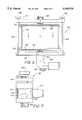
- FIG. 1is a front view of an anesthesia machine of the present invention.
- FIG. 2is a flow diagram of a patient breathing system for the anesthesia machine of FIG. 1.
- FIG. 3is a front view of the anesthesia machine of FIG. 1 showing the internal channels of a manifold.
- FIGS. 4A-4Care rear, plan, and front views of the manifold shown in FIG. 3.
- FIG. 5is a front view of a carbon dioxide absorber for the anesthesia machine of FIG. 1.
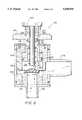
- FIG. 6is a sectional view of a pressure relief valve for the anesthesia machine of FIG. 1.
- FIG. 7is a front view of the pressure relief valve of FIG. 6, partially cut-away to show an inner wall of the valve.
- FIG. 1An exemplary embodiment of the anesthesia machine of the present invention is shown in FIG. 1 and is designated generally by reference numeral 10.
- the anesthesia machine 10includes a manifold 12 attached to a stand 14, which allows for height adjustment of the manifold 12.
- flowmeters 16 and 18Removably secured to the manifold are flowmeters 16 and 18, a vaporizer 20, a manometer 22, an inhalation valve 24, a pressure relief valve 26, an exhalation valve 28, and a carbon dioxide absorber 30.
- a breathing bag 32which is shown schematically in FIG. 2, is also connected to the manifold 12 via a port 34. These components, which are in fluid flow communication with each other as shown in FIG. 2, comprise a patient breathing system for the anesthesia machine 10.
- FIG. 2is a flow diagram of the patient breathing system that essentially includes two subsystems: (1) an oxygen/anesthesia gas delivery system 100 for mixing oxygen and anesthesia at a preset ratio; and (2) a closed loop recirculation system 200 for providing the patient with the oxygen/anesthesia gas mixture and collecting and recirculating gases exhaled by the patient.
- the breathing systemis particularly suited for veterinary use, but may be adapted for human use as well.
- oxygenflows from an oxygen source 36 into the vaporizer 20, which mixes the oxygen with a predetermined ratio of anesthesia, such as isofluorine.
- the anesthesiais provided to the vaporizer in liquid form, evaporated by the vaporizer, and mixed with oxygen.
- the oxygen/anesthesia mixtureis then introduced to the recirculation system 200.
- oxygencan be directly supplied to the recirculation system, bypassing the vaporizer 20, by activating flush valve 38.
- the recirculation system 200communicates with a patient via inhalation line 40 and exhalation line 42, which are connected to a breathing mask or other patient interface.
- inhalation valve 24opens to permit inhalation of the oxygen/anesthesia gas mixture.
- the exhalation valve 28closes the exhalation line 42.
- the inhalation valvecloses the inhalation line and the exhalation valve opens the exhalation line to direct the exhaled gas through the carbon dioxide absorber 30.
- the processed exhaled gas(which will contain oxygen and anesthesia gas) that exits the outlet of the carbon dioxide absorber 30 is merged with the fresh oxygen/anesthesia gas mixture and circulated to the patient via the inhalation line 40.
- the pressure relief valve 26vents gas from the breathing system when the pressure exceeds the threshold level set by the user.
- the manometer 22provides a visual reading of the pressure in the breathing system, and the breathing bag 32 provides an expandable volume for accommodating the exhaled and fresh gas entering the system.
- FIGS. 3 and 4A-4CThe interconnections of the various components illustrated in FIG. 2 are shown in FIGS. 3 and 4A-4C.
- the manifold 12has an internal oxygen channel 43 formed therein. Outlet ports of the flowmeters 16 and 18 are threadably secured to the manifold 12 and communicate with the oxygen channel 43 via ports 44 and 46. Inlet ports (not shown) of the flowmeters 16 and 18 are connected to the oxygen source 36 (FIG. 2) with tubing.
- flowmeter 16provides a variable flow rate of up to one liter per minute (l/min.), while flowmeter 18 provides a variable flow rate of up to five l/min.
- flowmeters 16 and 18can provide a precise oxygen flow rate of between zero to six l/min.
- Various combinations of flowmetersmay be used, however, and only one flowmeter may be used if desired.
- the vaporizer 20mixes the oxygen with isoflourine (or some other known anesthestic) and the mixture passes through tubing 56 (FIG. 3) and enters an internal inlet channel 52 formed in the manifold through port 54. Pure oxygen may also enter the inlet channel 52 via port 55 when the flush valve 38 is activated.
- An outlet port 60 of the inhalation valve 24is coupled to the inhalation line 40, which carries the gas mixture to the patient.
- the breathing bag 32is flow connected to the inlet channel 52 via port 34.
- the breathing bag 32inflates as the patient exhales and deflates as the patient inhales, and allows for "bagging" of the patient if necessary.
- the manometer 22is also flow connected to the inlet channel 52 via port 62.
- the manometer 22provides a visual reading of the pressure in the breathing system and assists in setting the desired pressure threshold setting of the pressure relief valve 26.
- the manometerallows for pressure readings between 0 and 30 centimeters of water with an expanded scale from 0 to 10.
- Conventional manometers for anesthesia machinestypically have a range from 0 to 60 centimeters of water. However, pressure readings of up to 30 centimeters of water are more than adequate, particularly since pressures above 20 centimeters of water may detrimentally affect the patient's lungs.
- the finely-calibrated manometer of the present inventionprovides a much more precise pressure reading than conventional manometers.
- An internal outlet channel 64is also formed within the manifold and receives exhaled gas from the patient. As shown, in FIGS. 3, 4B, and 4C, the exhalation valve 28 flow communicates with the outlet channel 64 via port 66 and has an inlet port 68 coupled to the exhalation line 42.
- the outlet channel 64directs exhaled gas into the carbon dioxide absorber 30 through inlet port 70.
- the carbon dioxide absorber 30includes a cylindrical casing 72, composed of clear plastic or glass, sandwiched between upper and lower mounting plates 74 and 76.
- the casing 72is open at its upper and lower ends, and the upper and lower edges may be chamfered.
- End caps 78are attached to the lower surface of the upper mounting plate 74 and the upper surface of the lower mounting plate 76. Each end cap includes an interior groove for supporting two seals 80, such as neoprene gaskets, with a sieve or filter 82 sandwiched therebetween.
- the casing 72, end caps 78, and seals 80form an airtight cannister for containing a material, such as calcium hydroxide, that readily absorbs carbon dioxide from the exhaled gas flowing through the cannister, as indicated by the arrows.
- the calcium hydroxideconverts to calcium carbonate as it absorbs carbon dioxide and is discarded periodically when saturated.
- Rods 84extend from the upper mounting plate 74 and are received in and secured to threaded openings in the lower mounting plate 76.
- the casing 72is placed on the seal 80 supported by the lower mounting plate 76 and end cap 78, and the rods 84 are inserted into openings in the upper mounting plate 74 and are threaded into the threaded openings in the lower mounting plate by turning the wing nuts 86.
- the rods and openings and the upper and lower mounting platescooperate to precisely and easily align the top and bottom mounting plates and casing to ensure an airtight cannister.
- the openings in the lower mounting platemay also be chamfered to further facilitate insertion of the rods.
- An inlet port 88is formed in the upper mounting plate 74 and includes a threaded shank for flow connecting the cannister to the outlet channel 64 via port 70, as shown in FIGS. 3 and 4C.
- An outlet port 90is formed in the lower mounting plate 76 and flow connects the cannister to the inlet channel 52 via tubing segment 92 and port 94 (FIGS. 4B and 4C) to merge the flow of processed exhaled gas with the fresh oxygen/anesthesia gas mixture.
- a bleed valve 93may be connected to port 90 to drain moisture from within the cannister.
- the pressure relief valve 26flow communicates with the outlet channel 64 via port 96.
- the pressure relief valve 26includes a threaded shank 98 that engages threaded port 96 to secure the pressure relief valve 26 to the manifold 12.
- the pressure relief valve 26also includes a housing having an outer wall 102 and an inner wall 104 that defines a chamber 106 in flow communication with the outlet channel 64 via an opening in a valve seat 108.
- a plastic poppet 110is normally biased against the valve seat 108 by a coil spring 112.
- a pressure adjustment knob 114includes a shaft 116 that threadedly engages to an upper portion of the inner wall 104.
- the shaftis hollow and includes an inner lip 118 for engaging one end of the coil spring 112.
- a usersets the predetermined pressure level by rotating the knob 114 to compress spring 112, whose lower end is seated against poppet 110. Rotation of the knob 114 varies the compression of the spring 112 and thus the biasing force adjustably acting to hold the poppet 110 in a valve closure position against valve seat 108.
- the shaft 116is preferably finely threaded to precisely adjust the pressure level.
- the inner wall 104includes circumferentially elongated ports 120, as shown in FIG. 7, which communicate with a channel formed between the inner and outer walls to define an annular flow path 122.
- the flow path 122communicates with a vent 124 through which pressure-relieving gas is vented to a vacuum line (not shown) or other location preferably leading away from operating room personnel.
- the pressure relief valvealso includes vent override means for preventing the flow of gas into the chamber independent of the pressure in the breathing system without changing the pressure threshold setting.
- the vent override meansincludes a plunger 126 having a shaft 128 positioned within the hollow shaft 116 and coil spring 112.
- a spring 130disposed between the adjustment knob 114 and the top of the plunger 126, biases the plunger 126 in a direction away from the pressure adjustment knob 114 and out of contact with the poppet 110.
- a plunger piston 132with an O-ring 134 lodged in an annular groove, stabilizes plunger reciprocating motion within the shaft 116.
- valve seatmay include a slot below the poppet for receiving a slidable member that is movable by the user. To override the pressure relief valve, the user slides the member into position blocking the opening of the valve seat communicating with the breathing system.
- Other embodimentswill be readily apparent to those skilled in the art.
- each of the internal channels in the manifoldincludes, as shown in FIGS. 3 and 4A-4C, a cleaning port 136 that is closed with a cap 138 during use. When cleaning is desired, the caps 138 are removed, allowing access to the cleaning ports. Since the internal channels preferably consist of straight, cylindrical sections formed by boring or molding, they can be easily cleaned with a brush or other cleaning means.
- the components of the anesthesia machineincluding the inhalation and exhalation valves 24 and 28, the pressure relief valve 26, the manometer 22, and the flowmeters 16 and 18 may be removed from the manifold for cleaning of their respective ports.
- the inhalation and exhalation valvesinclude stems 25 and 29, and O-rings 27, that are friction fitted within the ports 58 and 66 (FIG. 4C). As a result, these valves can be rotated relative to the manifold during use with the O-rings 27 providing an effective seal.
- the pressure relief valve, flowmeters, and manometerare shown as threadably secured to the manifold, these components may also be attached to the manifold in a manner similar to the inhalation and exhalation valves.
- Rotation of the exhalation and inhalation valves relative to the manifoldalso assists in preventing kinking of the inhalation and exhalation lines leading to the patient.
- the outlet ports of the inhalation and exhalation valvesmay also be angled downward (e.g., 45° downward) to further prevent kinking of the lines since the manifold is typically higher than the patient during surgery.
Landscapes
- Health & Medical Sciences (AREA)
- Pulmonology (AREA)
- Emergency Medicine (AREA)
- Heart & Thoracic Surgery (AREA)
- Anesthesiology (AREA)
- Biomedical Technology (AREA)
- Engineering & Computer Science (AREA)
- Hematology (AREA)
- Life Sciences & Earth Sciences (AREA)
- Animal Behavior & Ethology (AREA)
- General Health & Medical Sciences (AREA)
- Public Health (AREA)
- Veterinary Medicine (AREA)
- Respiratory Apparatuses And Protective Means (AREA)
Abstract
Description
Claims (28)
Priority Applications (3)
| Application Number | Priority Date | Filing Date | Title |
|---|---|---|---|
| US08/397,671US5568910A (en) | 1995-03-02 | 1995-03-02 | Anesthesia machine |
| CA002170188ACA2170188C (en) | 1995-03-02 | 1996-02-23 | Anesthesia machine |
| US08/738,497US5743257A (en) | 1995-03-02 | 1996-10-28 | Dual valve, anesthesia machine having same, and method for using same |
Applications Claiming Priority (1)
| Application Number | Priority Date | Filing Date | Title |
|---|---|---|---|
| US08/397,671US5568910A (en) | 1995-03-02 | 1995-03-02 | Anesthesia machine |
Related Child Applications (1)
| Application Number | Title | Priority Date | Filing Date |
|---|---|---|---|
| US08/738,497ContinuationUS5743257A (en) | 1995-03-02 | 1996-10-28 | Dual valve, anesthesia machine having same, and method for using same |
Publications (1)
| Publication Number | Publication Date |
|---|---|
| US5568910Atrue US5568910A (en) | 1996-10-29 |
Family
ID=23572165
Family Applications (2)
| Application Number | Title | Priority Date | Filing Date |
|---|---|---|---|
| US08/397,671Expired - Fee RelatedUS5568910A (en) | 1995-03-02 | 1995-03-02 | Anesthesia machine |
| US08/738,497Expired - LifetimeUS5743257A (en) | 1995-03-02 | 1996-10-28 | Dual valve, anesthesia machine having same, and method for using same |
Family Applications After (1)
| Application Number | Title | Priority Date | Filing Date |
|---|---|---|---|
| US08/738,497Expired - LifetimeUS5743257A (en) | 1995-03-02 | 1996-10-28 | Dual valve, anesthesia machine having same, and method for using same |
Country Status (2)
| Country | Link |
|---|---|
| US (2) | US5568910A (en) |
| CA (1) | CA2170188C (en) |
Cited By (57)
| Publication number | Priority date | Publication date | Assignee | Title |
|---|---|---|---|---|
| US5743257A (en)* | 1995-03-02 | 1998-04-28 | Delmarva Laboratories, Inc. | Dual valve, anesthesia machine having same, and method for using same |
| US5791339A (en)* | 1997-03-13 | 1998-08-11 | Nellcor Puritan Bennettt Incorprated | Spring piloted safety valve with jet venturi bias |
| WO2001043803A1 (en)* | 1999-12-15 | 2001-06-21 | Colin Dunlop | Anaesthetic apparatus |
| US6634355B2 (en) | 1999-06-11 | 2003-10-21 | Colas Marie-Jose | Single breath induction anesthesia apparatus |
| US6644313B2 (en)* | 2001-02-01 | 2003-11-11 | Fisher & Paykel Healthcare Limited | Breathing assistance apparatus |
| US6655379B2 (en)* | 1998-03-16 | 2003-12-02 | Nektar Therapeutics | Aerosolized active agent delivery |
| AU784306B2 (en)* | 1999-12-15 | 2006-03-09 | Colin Dunlop | Anaesthetic apparatus |
| US20060254587A1 (en)* | 2005-05-13 | 2006-11-16 | Anesthetic Gas Reclamation, Llc | Anesthetic gas reclamation system and method |
| US20060254590A1 (en)* | 2005-05-13 | 2006-11-16 | Anesthetic Gas Reclamation, Llc | Method and apparatus for self-contained anesthetic gas reclamation |
| US20060254586A1 (en)* | 2005-05-13 | 2006-11-16 | Anesthetic Gas Reclamation, Llc | Method of low flow anesthetic gas scavenging and dynamic collection apparatus therefor |
| US20080119820A1 (en)* | 2006-09-20 | 2008-05-22 | Phan Phillip C | Methods for Delivering Volatile Anesthetics for Regional Anesthesia and/or Pain Relief |
| US20090126729A1 (en)* | 2007-11-15 | 2009-05-21 | Smith S E | Anesthesia Apparatus Preoperative Checkout Device |
| US20090126730A1 (en)* | 2007-11-15 | 2009-05-21 | Smith S E | Anesthesia Apparatus Preoperative Checkout Device |
| US20090223567A1 (en)* | 2008-03-05 | 2009-09-10 | Ahearn David J | Nitrous Oxide Safety System |
| US20100148501A1 (en)* | 2008-12-10 | 2010-06-17 | Swagelok Company | Ferrule assembly for conduit fitting |
| US20110067698A1 (en)* | 2009-09-22 | 2011-03-24 | O-Two Medical Technologies Inc. | Handheld device for delivering continuous positive airway pressure |
| EP2363022A2 (en) | 2003-10-22 | 2011-09-07 | Fred Hutchinson Cancer Research Center | Use of oxygen antagonists for the therapeutic treatment of mammals |
| USD653749S1 (en) | 2010-04-27 | 2012-02-07 | Nellcor Puritan Bennett Llc | Exhalation module filter body |
| USD655405S1 (en) | 2010-04-27 | 2012-03-06 | Nellcor Puritan Bennett Llc | Filter and valve body for an exhalation module |
| USD655809S1 (en) | 2010-04-27 | 2012-03-13 | Nellcor Puritan Bennett Llc | Valve body with integral flow meter for an exhalation module |
| US8267081B2 (en) | 2009-02-20 | 2012-09-18 | Baxter International Inc. | Inhaled anesthetic agent therapy and delivery system |
| US20130000637A1 (en)* | 2011-07-02 | 2013-01-03 | Dräger Medical GmbH | Respiration system for an anesthesia apparatus |
| US8408200B2 (en) | 1998-10-09 | 2013-04-02 | Novartis Ag | Flow resistance modulated aerosolized active agent delivery |
| US8434479B2 (en) | 2009-02-27 | 2013-05-07 | Covidien Lp | Flow rate compensation for transient thermal response of hot-wire anemometers |
| US8439036B2 (en) | 2009-12-01 | 2013-05-14 | Covidien Lp | Exhalation valve assembly with integral flow sensor |
| US8439037B2 (en) | 2009-12-01 | 2013-05-14 | Covidien Lp | Exhalation valve assembly with integrated filter and flow sensor |
| US8457706B2 (en) | 2008-05-16 | 2013-06-04 | Covidien Lp | Estimation of a physiological parameter using a neural network |
| US8469031B2 (en) | 2009-12-01 | 2013-06-25 | Covidien Lp | Exhalation valve assembly with integrated filter |
| US8469030B2 (en) | 2009-12-01 | 2013-06-25 | Covidien Lp | Exhalation valve assembly with selectable contagious/non-contagious latch |
| USD692556S1 (en) | 2013-03-08 | 2013-10-29 | Covidien Lp | Expiratory filter body of an exhalation module |
| USD693001S1 (en) | 2013-03-08 | 2013-11-05 | Covidien Lp | Neonate expiratory filter assembly of an exhalation module |
| USD701601S1 (en) | 2013-03-08 | 2014-03-25 | Covidien Lp | Condensate vial of an exhalation module |
| WO2013040198A3 (en)* | 2011-09-13 | 2014-05-08 | Resmed Limited | Vent arrangement for respiratory mask |
| CN103853064A (en)* | 2012-12-04 | 2014-06-11 | 深圳迈瑞生物医疗电子股份有限公司 | Fluid electronic control system and anaesthesia machine |
| US8800557B2 (en) | 2003-07-29 | 2014-08-12 | Covidien Lp | System and process for supplying respiratory gas under pressure or volumetrically |
| USD731048S1 (en) | 2013-03-08 | 2015-06-02 | Covidien Lp | EVQ diaphragm of an exhalation module |
| USD731065S1 (en) | 2013-03-08 | 2015-06-02 | Covidien Lp | EVQ pressure sensor filter of an exhalation module |
| USD731049S1 (en) | 2013-03-05 | 2015-06-02 | Covidien Lp | EVQ housing of an exhalation module |
| USD736905S1 (en) | 2013-03-08 | 2015-08-18 | Covidien Lp | Exhalation module EVQ housing |
| US9144658B2 (en) | 2012-04-30 | 2015-09-29 | Covidien Lp | Minimizing imposed expiratory resistance of mechanical ventilator by optimizing exhalation valve control |
| USD744095S1 (en) | 2013-03-08 | 2015-11-24 | Covidien Lp | Exhalation module EVQ internal flow sensor |
| US9364624B2 (en) | 2011-12-07 | 2016-06-14 | Covidien Lp | Methods and systems for adaptive base flow |
| US9498589B2 (en) | 2011-12-31 | 2016-11-22 | Covidien Lp | Methods and systems for adaptive base flow and leak compensation |
| USD775345S1 (en) | 2015-04-10 | 2016-12-27 | Covidien Lp | Ventilator console |
| US9629971B2 (en) | 2011-04-29 | 2017-04-25 | Covidien Lp | Methods and systems for exhalation control and trajectory optimization |
| US9649458B2 (en) | 2008-09-30 | 2017-05-16 | Covidien Lp | Breathing assistance system with multiple pressure sensors |
| US9675544B2 (en) | 2008-01-22 | 2017-06-13 | The Board Of Regents Of The University Of Texas System | Volatile anesthetic compositions comprising extractive solvents for regional anesthesia and/or pain relief |
| US9950135B2 (en) | 2013-03-15 | 2018-04-24 | Covidien Lp | Maintaining an exhalation valve sensor assembly |
| US20180200475A1 (en)* | 2017-01-13 | 2018-07-19 | Silverbow Development, Llc | Remote oxygen flow adjustment |
| US10047887B2 (en) | 2010-01-21 | 2018-08-14 | Swagelok Company | Conduit gripping device having retaining structure for conduit fitting |
| US10076619B2 (en) | 2012-09-11 | 2018-09-18 | Resmed Limited | Vent arrangement for respiratory mask |
| US10307561B2 (en) | 2013-03-14 | 2019-06-04 | Resmed Limited | Vent arrangement for respiratory device |
| US10328222B2 (en) | 2013-03-14 | 2019-06-25 | ResMed Pty Ltd | Vent device for use with a respiratory device |
| US10413642B2 (en) | 2015-04-28 | 2019-09-17 | James Michael Berry | System for dynamic control of medical vacuum |
| US20210052843A1 (en)* | 2019-08-23 | 2021-02-25 | GE Precision Healthcare LLC | Connector and seal used therefor and anesthesia machine using the connector |
| CN114288505A (en)* | 2016-02-08 | 2022-04-08 | 德尔格制造股份两合公司 | Device for providing a respiratory gas flow to be administered with an anesthetic agent |
| US11896767B2 (en) | 2020-03-20 | 2024-02-13 | Covidien Lp | Model-driven system integration in medical ventilators |
Families Citing this family (9)
| Publication number | Priority date | Publication date | Assignee | Title |
|---|---|---|---|---|
| EP0861103B1 (en)* | 1995-09-28 | 2000-03-08 | Nellcor Puritan Bennett Incorporated | Oxygen-conserving regulator assembly |
| BRPI0406629A (en)* | 2003-01-06 | 2005-12-06 | Pierluca Lombardi | Apparatus and method for preparing graft ducts and apparatus for regulating applied pressure during a medical procedure |
| US6854334B2 (en)* | 2003-01-28 | 2005-02-15 | Mercury Enterprises, Inc. | Negative inspiratory force manometer apparatus |
| USD495049S1 (en) | 2003-06-24 | 2004-08-24 | Taga Medical Technologies, Inc | Oxygen conserving regulator |
| DE102004020133B3 (en)* | 2004-04-24 | 2005-08-11 | Dräger Medical AG & Co. KGaA | Device used as a breathing system comprises an absorber, centering notches arranged on the front side of a guide plate, and a centering pin fixed on the absorber holder |
| US20060086359A1 (en)* | 2004-10-22 | 2006-04-27 | Taga Medical Technologies, Inc. | Dual scale control knob for an oxygen conserving regulator |
| NL1034284C2 (en)* | 2007-08-24 | 2009-02-25 | Emergency Pulmonary Care B V | Adjustable valve. |
| CN104874071B (en)* | 2014-02-28 | 2018-07-17 | 北京谊安医疗系统股份有限公司 | Gas pressurizer for Anesthesia machine and the Anesthesia machine with it |
| US10039892B2 (en) | 2015-03-25 | 2018-08-07 | Diane Miller | Pediatric induction of anesthesia |
Citations (26)
| Publication number | Priority date | Publication date | Assignee | Title |
|---|---|---|---|---|
| US526176A (en)* | 1894-09-18 | Valve | ||
| FR403255A (en)* | 1909-05-22 | 1909-10-29 | Jacques Mandet | High pressure gas valve |
| US954180A (en)* | 1909-06-11 | 1910-04-05 | Otto A Giffen | Gas-cut-off valve. |
| US1044106A (en)* | 1911-06-22 | 1912-11-12 | John L Vidar | Automatic expansion-valve. |
| US1656670A (en)* | 1923-04-23 | 1928-01-17 | Greenhouse Samuel | Pressure-regulating valve |
| US2292294A (en)* | 1940-10-07 | 1942-08-04 | Lincoln Eng Co | Relief valve |
| US2674260A (en)* | 1950-02-13 | 1954-04-06 | H A Thrush & Company | Water relief valve |
| DE1010835B (en)* | 1954-01-02 | 1957-06-19 | Draegerwerk Ag | Breathing apparatus with pressurized gas supply |
| US2861569A (en)* | 1955-04-01 | 1958-11-25 | John H Emerson | Valve apparatus for dispensing gas |
| US2968295A (en)* | 1956-03-02 | 1961-01-17 | Haller Richard | Internal combustion engine brake |
| US3212523A (en)* | 1963-09-27 | 1965-10-19 | Parker Hannifin Corp | Fluid system and relief valve assembly therefor |
| US3292895A (en)* | 1963-07-02 | 1966-12-20 | Air Liquide | Valve for pressure gas container |
| US3426794A (en)* | 1965-09-29 | 1969-02-11 | Drager Otto H | Control apparatus for breathing apparatus |
| US3568695A (en)* | 1969-04-07 | 1971-03-09 | Raymond Vincent Heelan Jr | Fluid pressure relief vacuum relief, and overturn check valve |
| US3604448A (en)* | 1969-01-10 | 1971-09-14 | Rocco Anthony Marrese | Closed exhaust discharge system for anesthesia machines |
| US3636966A (en)* | 1969-10-24 | 1972-01-25 | Nasa | Underwater space suit pressure control regulator |
| US3719401A (en)* | 1971-04-28 | 1973-03-06 | Fiat Spa | Solenoid-operated hydraulic switching valve |
| US3800793A (en)* | 1971-12-23 | 1974-04-02 | R Marrese | Anesthesia apparatus having negative pressure relief means |
| US3981328A (en)* | 1974-08-09 | 1976-09-21 | Kabushiki Kaisha Neriki | Hand-operable takeout valve for a fluid pressurized container |
| US4039139A (en)* | 1974-08-22 | 1977-08-02 | Bird F M | Ventilator and method |
| US4044793A (en)* | 1975-08-25 | 1977-08-30 | Shiley Laboratories, Inc. | Relief valve |
| US4406302A (en)* | 1981-05-26 | 1983-09-27 | Puritan-Bennett Corporation | Pop-off gas evacuator valve for anesthesia machine |
| US4941504A (en)* | 1987-09-30 | 1990-07-17 | Jacques Beauvir | Manual fluid-control valve with limited closing pressure |
| US4967791A (en)* | 1989-04-26 | 1990-11-06 | The Boeing Company | Pressure activated check valve |
| US5016627A (en)* | 1988-11-28 | 1991-05-21 | Auergesellschaft Gmbh | Lung-governed valve |
| US5165445A (en)* | 1991-08-21 | 1992-11-24 | Gits Manufacturing Company | Relief vent apparatus |
Family Cites Families (9)
| Publication number | Priority date | Publication date | Assignee | Title |
|---|---|---|---|---|
| US3276446A (en)* | 1962-09-06 | 1966-10-04 | Air Reduction | Semi-closed anesthetic system |
| US3688794A (en)* | 1970-08-10 | 1972-09-05 | Bird F M | Exhalation valve for respirator |
| US3752186A (en)* | 1970-10-09 | 1973-08-14 | Dryden Corp | Venting device and method for anesthetic administration |
| US3738360A (en)* | 1971-04-07 | 1973-06-12 | G Dryden | Unitary disposable circle absorption canister assembly |
| US3938551A (en)* | 1972-01-17 | 1976-02-17 | Henkin Melvyn Lane | Anesthesia rebreathing apparatus |
| US4103704A (en)* | 1977-02-16 | 1978-08-01 | Eaton Corporation | Safety relief valve |
| US4823828A (en)* | 1987-05-28 | 1989-04-25 | Mcginnis Gerald E | Pressure relief valve |
| US4909269A (en)* | 1987-09-21 | 1990-03-20 | Union Carbide Corporation | High pressure regulator valve |
| US5568910A (en)* | 1995-03-02 | 1996-10-29 | Delmarva Laboratories, Inc. | Anesthesia machine |
- 1995
- 1995-03-02USUS08/397,671patent/US5568910A/ennot_activeExpired - Fee Related
- 1996
- 1996-02-23CACA002170188Apatent/CA2170188C/ennot_activeExpired - Fee Related
- 1996-10-28USUS08/738,497patent/US5743257A/ennot_activeExpired - Lifetime
Patent Citations (26)
| Publication number | Priority date | Publication date | Assignee | Title |
|---|---|---|---|---|
| US526176A (en)* | 1894-09-18 | Valve | ||
| FR403255A (en)* | 1909-05-22 | 1909-10-29 | Jacques Mandet | High pressure gas valve |
| US954180A (en)* | 1909-06-11 | 1910-04-05 | Otto A Giffen | Gas-cut-off valve. |
| US1044106A (en)* | 1911-06-22 | 1912-11-12 | John L Vidar | Automatic expansion-valve. |
| US1656670A (en)* | 1923-04-23 | 1928-01-17 | Greenhouse Samuel | Pressure-regulating valve |
| US2292294A (en)* | 1940-10-07 | 1942-08-04 | Lincoln Eng Co | Relief valve |
| US2674260A (en)* | 1950-02-13 | 1954-04-06 | H A Thrush & Company | Water relief valve |
| DE1010835B (en)* | 1954-01-02 | 1957-06-19 | Draegerwerk Ag | Breathing apparatus with pressurized gas supply |
| US2861569A (en)* | 1955-04-01 | 1958-11-25 | John H Emerson | Valve apparatus for dispensing gas |
| US2968295A (en)* | 1956-03-02 | 1961-01-17 | Haller Richard | Internal combustion engine brake |
| US3292895A (en)* | 1963-07-02 | 1966-12-20 | Air Liquide | Valve for pressure gas container |
| US3212523A (en)* | 1963-09-27 | 1965-10-19 | Parker Hannifin Corp | Fluid system and relief valve assembly therefor |
| US3426794A (en)* | 1965-09-29 | 1969-02-11 | Drager Otto H | Control apparatus for breathing apparatus |
| US3604448A (en)* | 1969-01-10 | 1971-09-14 | Rocco Anthony Marrese | Closed exhaust discharge system for anesthesia machines |
| US3568695A (en)* | 1969-04-07 | 1971-03-09 | Raymond Vincent Heelan Jr | Fluid pressure relief vacuum relief, and overturn check valve |
| US3636966A (en)* | 1969-10-24 | 1972-01-25 | Nasa | Underwater space suit pressure control regulator |
| US3719401A (en)* | 1971-04-28 | 1973-03-06 | Fiat Spa | Solenoid-operated hydraulic switching valve |
| US3800793A (en)* | 1971-12-23 | 1974-04-02 | R Marrese | Anesthesia apparatus having negative pressure relief means |
| US3981328A (en)* | 1974-08-09 | 1976-09-21 | Kabushiki Kaisha Neriki | Hand-operable takeout valve for a fluid pressurized container |
| US4039139A (en)* | 1974-08-22 | 1977-08-02 | Bird F M | Ventilator and method |
| US4044793A (en)* | 1975-08-25 | 1977-08-30 | Shiley Laboratories, Inc. | Relief valve |
| US4406302A (en)* | 1981-05-26 | 1983-09-27 | Puritan-Bennett Corporation | Pop-off gas evacuator valve for anesthesia machine |
| US4941504A (en)* | 1987-09-30 | 1990-07-17 | Jacques Beauvir | Manual fluid-control valve with limited closing pressure |
| US5016627A (en)* | 1988-11-28 | 1991-05-21 | Auergesellschaft Gmbh | Lung-governed valve |
| US4967791A (en)* | 1989-04-26 | 1990-11-06 | The Boeing Company | Pressure activated check valve |
| US5165445A (en)* | 1991-08-21 | 1992-11-24 | Gits Manufacturing Company | Relief vent apparatus |
Cited By (95)
| Publication number | Priority date | Publication date | Assignee | Title |
|---|---|---|---|---|
| US5743257A (en)* | 1995-03-02 | 1998-04-28 | Delmarva Laboratories, Inc. | Dual valve, anesthesia machine having same, and method for using same |
| US5791339A (en)* | 1997-03-13 | 1998-08-11 | Nellcor Puritan Bennettt Incorprated | Spring piloted safety valve with jet venturi bias |
| US5884623A (en)* | 1997-03-13 | 1999-03-23 | Nellcor Puritan Bennett Incorporated | Spring piloted safety valve with jet venturi bias |
| US6161539A (en)* | 1997-03-13 | 2000-12-19 | Nellcor Puritan Bennett Incorporated | Spring piloted safety valve with jet venturi bias |
| US6655379B2 (en)* | 1998-03-16 | 2003-12-02 | Nektar Therapeutics | Aerosolized active agent delivery |
| US8408200B2 (en) | 1998-10-09 | 2013-04-02 | Novartis Ag | Flow resistance modulated aerosolized active agent delivery |
| US6634355B2 (en) | 1999-06-11 | 2003-10-21 | Colas Marie-Jose | Single breath induction anesthesia apparatus |
| WO2001043803A1 (en)* | 1999-12-15 | 2001-06-21 | Colin Dunlop | Anaesthetic apparatus |
| GB2375966B (en)* | 1999-12-15 | 2004-09-22 | Colin Dunlop | Anaesthetic apparatus |
| US6948493B2 (en) | 1999-12-15 | 2005-09-27 | Colin Dunlop | Anaesthetic apparatus |
| AU784306B2 (en)* | 1999-12-15 | 2006-03-09 | Colin Dunlop | Anaesthetic apparatus |
| GB2375966A (en)* | 1999-12-15 | 2002-12-04 | Colin Dunlop | Anaesthetic apparatus |
| US6644313B2 (en)* | 2001-02-01 | 2003-11-11 | Fisher & Paykel Healthcare Limited | Breathing assistance apparatus |
| US8800557B2 (en) | 2003-07-29 | 2014-08-12 | Covidien Lp | System and process for supplying respiratory gas under pressure or volumetrically |
| EP2949212A1 (en) | 2003-10-22 | 2015-12-02 | Fred Hutchinson Cancer Research Center | Use of oxygen antagonists for ex vivo preservation of tissues or organs |
| EP2363022A2 (en) | 2003-10-22 | 2011-09-07 | Fred Hutchinson Cancer Research Center | Use of oxygen antagonists for the therapeutic treatment of mammals |
| US7644594B2 (en) | 2005-05-13 | 2010-01-12 | Anesthetic Gas Reclamation, L.L.C. | Method and apparatus for self-contained anesthetic gas reclamation |
| US20060254587A1 (en)* | 2005-05-13 | 2006-11-16 | Anesthetic Gas Reclamation, Llc | Anesthetic gas reclamation system and method |
| US20060254590A1 (en)* | 2005-05-13 | 2006-11-16 | Anesthetic Gas Reclamation, Llc | Method and apparatus for self-contained anesthetic gas reclamation |
| US20060254586A1 (en)* | 2005-05-13 | 2006-11-16 | Anesthetic Gas Reclamation, Llc | Method of low flow anesthetic gas scavenging and dynamic collection apparatus therefor |
| US7596965B2 (en) | 2005-05-13 | 2009-10-06 | Anesthetic Gas Reclamation, Llc | Anesthetic gas reclamation system and method |
| US7628034B2 (en) | 2005-05-13 | 2009-12-08 | Anesthetic Gas Reclamation, Llc | Method of low flow anesthetic gas scavenging and dynamic collection apparatus therefor |
| US20060254589A1 (en)* | 2005-05-13 | 2006-11-16 | Anesthetic Gas Reclamation, Llc | Method and apparatus for anesthetic gas reclamation with compression stage |
| US7669438B2 (en) | 2005-05-13 | 2010-03-02 | Anesthetic Gas Reclamation, Llc | Method and apparatus for anesthetic gas reclamation with compression stage |
| US20080119820A1 (en)* | 2006-09-20 | 2008-05-22 | Phan Phillip C | Methods for Delivering Volatile Anesthetics for Regional Anesthesia and/or Pain Relief |
| US10799466B2 (en) | 2006-09-20 | 2020-10-13 | The Board Of Regents Of The University Of Texas System | Methods for delivering volatile anesthetics for regional anesthesia and/or pain relief |
| US10357464B2 (en) | 2006-09-20 | 2019-07-23 | The Board Of Regents Of The University Of Texas System | Methods for delivering volatile anesthetics for regional anesthesia and/or pain relief |
| US20090126729A1 (en)* | 2007-11-15 | 2009-05-21 | Smith S E | Anesthesia Apparatus Preoperative Checkout Device |
| US20090126730A1 (en)* | 2007-11-15 | 2009-05-21 | Smith S E | Anesthesia Apparatus Preoperative Checkout Device |
| US10420720B2 (en) | 2008-01-22 | 2019-09-24 | The Board Of Regents Of The University Of Texas System | Volatile anesthetic compositions comprising extractive solvents for regional anesthesia and/or pain relief |
| US9675544B2 (en) | 2008-01-22 | 2017-06-13 | The Board Of Regents Of The University Of Texas System | Volatile anesthetic compositions comprising extractive solvents for regional anesthesia and/or pain relief |
| US20090223567A1 (en)* | 2008-03-05 | 2009-09-10 | Ahearn David J | Nitrous Oxide Safety System |
| US10076618B2 (en) | 2008-03-05 | 2018-09-18 | David J. Ahearn | Nitrous oxide safety system |
| US8457706B2 (en) | 2008-05-16 | 2013-06-04 | Covidien Lp | Estimation of a physiological parameter using a neural network |
| US9649458B2 (en) | 2008-09-30 | 2017-05-16 | Covidien Lp | Breathing assistance system with multiple pressure sensors |
| US20100148501A1 (en)* | 2008-12-10 | 2010-06-17 | Swagelok Company | Ferrule assembly for conduit fitting |
| US8267081B2 (en) | 2009-02-20 | 2012-09-18 | Baxter International Inc. | Inhaled anesthetic agent therapy and delivery system |
| US8434479B2 (en) | 2009-02-27 | 2013-05-07 | Covidien Lp | Flow rate compensation for transient thermal response of hot-wire anemometers |
| US8905024B2 (en) | 2009-02-27 | 2014-12-09 | Covidien Lp | Flow rate compensation for transient thermal response of hot-wire anemometers |
| US20110067698A1 (en)* | 2009-09-22 | 2011-03-24 | O-Two Medical Technologies Inc. | Handheld device for delivering continuous positive airway pressure |
| US8439037B2 (en) | 2009-12-01 | 2013-05-14 | Covidien Lp | Exhalation valve assembly with integrated filter and flow sensor |
| US8469031B2 (en) | 2009-12-01 | 2013-06-25 | Covidien Lp | Exhalation valve assembly with integrated filter |
| US8469030B2 (en) | 2009-12-01 | 2013-06-25 | Covidien Lp | Exhalation valve assembly with selectable contagious/non-contagious latch |
| US8439036B2 (en) | 2009-12-01 | 2013-05-14 | Covidien Lp | Exhalation valve assembly with integral flow sensor |
| US9987457B2 (en) | 2009-12-01 | 2018-06-05 | Covidien Lp | Exhalation valve assembly with integral flow sensor |
| US9205221B2 (en) | 2009-12-01 | 2015-12-08 | Covidien Lp | Exhalation valve assembly with integral flow sensor |
| US10247336B2 (en) | 2010-01-21 | 2019-04-02 | Swagelok Company | Conduit gripping device having retaining structure for conduit fitting |
| US10415730B2 (en) | 2010-01-21 | 2019-09-17 | Swagelok Company | Conduit gripping device having retaining structure for conduit fitting |
| US10760722B2 (en) | 2010-01-21 | 2020-09-01 | Swagelok Company | Fitting subassembly with retained ferrule |
| US10047887B2 (en) | 2010-01-21 | 2018-08-14 | Swagelok Company | Conduit gripping device having retaining structure for conduit fitting |
| USD655809S1 (en) | 2010-04-27 | 2012-03-13 | Nellcor Puritan Bennett Llc | Valve body with integral flow meter for an exhalation module |
| USD655405S1 (en) | 2010-04-27 | 2012-03-06 | Nellcor Puritan Bennett Llc | Filter and valve body for an exhalation module |
| USD653749S1 (en) | 2010-04-27 | 2012-02-07 | Nellcor Puritan Bennett Llc | Exhalation module filter body |
| US11638796B2 (en) | 2011-04-29 | 2023-05-02 | Covidien Lp | Methods and systems for exhalation control and trajectory optimization |
| US10850056B2 (en) | 2011-04-29 | 2020-12-01 | Covidien Lp | Methods and systems for exhalation control and trajectory optimization |
| US9629971B2 (en) | 2011-04-29 | 2017-04-25 | Covidien Lp | Methods and systems for exhalation control and trajectory optimization |
| US20130000637A1 (en)* | 2011-07-02 | 2013-01-03 | Dräger Medical GmbH | Respiration system for an anesthesia apparatus |
| US9399104B2 (en)* | 2011-07-02 | 2016-07-26 | Drägerwerk AG & Co. KGaA | Respiration system for an anesthesia apparatus |
| US10029058B2 (en) | 2011-09-13 | 2018-07-24 | Resmed Limited | Vent arrangement for respiratory mask |
| WO2013040198A3 (en)* | 2011-09-13 | 2014-05-08 | Resmed Limited | Vent arrangement for respiratory mask |
| US12268812B2 (en) | 2011-09-13 | 2025-04-08 | ResMed Pty Ltd | Vent arrangement for respiratory mask |
| US11497869B2 (en) | 2011-12-07 | 2022-11-15 | Covidien Lp | Methods and systems for adaptive base flow |
| US10543327B2 (en) | 2011-12-07 | 2020-01-28 | Covidien Lp | Methods and systems for adaptive base flow |
| US9364624B2 (en) | 2011-12-07 | 2016-06-14 | Covidien Lp | Methods and systems for adaptive base flow |
| US10709854B2 (en) | 2011-12-31 | 2020-07-14 | Covidien Lp | Methods and systems for adaptive base flow and leak compensation |
| US9498589B2 (en) | 2011-12-31 | 2016-11-22 | Covidien Lp | Methods and systems for adaptive base flow and leak compensation |
| US11833297B2 (en) | 2011-12-31 | 2023-12-05 | Covidien Lp | Methods and systems for adaptive base flow and leak compensation |
| US9144658B2 (en) | 2012-04-30 | 2015-09-29 | Covidien Lp | Minimizing imposed expiratory resistance of mechanical ventilator by optimizing exhalation valve control |
| US10960159B2 (en) | 2012-09-11 | 2021-03-30 | ResMed Pty Ltd | Vent arrangement for respiratory mask |
| US11865267B2 (en) | 2012-09-11 | 2024-01-09 | ResMed Pty Ltd | Vent arrangement for respiratory mask |
| US10076619B2 (en) | 2012-09-11 | 2018-09-18 | Resmed Limited | Vent arrangement for respiratory mask |
| CN103853064A (en)* | 2012-12-04 | 2014-06-11 | 深圳迈瑞生物医疗电子股份有限公司 | Fluid electronic control system and anaesthesia machine |
| USD731049S1 (en) | 2013-03-05 | 2015-06-02 | Covidien Lp | EVQ housing of an exhalation module |
| USD736905S1 (en) | 2013-03-08 | 2015-08-18 | Covidien Lp | Exhalation module EVQ housing |
| USD744095S1 (en) | 2013-03-08 | 2015-11-24 | Covidien Lp | Exhalation module EVQ internal flow sensor |
| USD731048S1 (en) | 2013-03-08 | 2015-06-02 | Covidien Lp | EVQ diaphragm of an exhalation module |
| USD693001S1 (en) | 2013-03-08 | 2013-11-05 | Covidien Lp | Neonate expiratory filter assembly of an exhalation module |
| USD731065S1 (en) | 2013-03-08 | 2015-06-02 | Covidien Lp | EVQ pressure sensor filter of an exhalation module |
| USD701601S1 (en) | 2013-03-08 | 2014-03-25 | Covidien Lp | Condensate vial of an exhalation module |
| USD692556S1 (en) | 2013-03-08 | 2013-10-29 | Covidien Lp | Expiratory filter body of an exhalation module |
| US10881830B2 (en) | 2013-03-14 | 2021-01-05 | ResMed Pty Ltd | Vent arrangement for a respiratory device |
| US10307561B2 (en) | 2013-03-14 | 2019-06-04 | Resmed Limited | Vent arrangement for respiratory device |
| US10328222B2 (en) | 2013-03-14 | 2019-06-25 | ResMed Pty Ltd | Vent device for use with a respiratory device |
| US11793969B2 (en) | 2013-03-14 | 2023-10-24 | ResMed Pty Ltd | Vent arrangement for a respiratory device |
| US9950135B2 (en) | 2013-03-15 | 2018-04-24 | Covidien Lp | Maintaining an exhalation valve sensor assembly |
| USD775345S1 (en) | 2015-04-10 | 2016-12-27 | Covidien Lp | Ventilator console |
| US10413642B2 (en) | 2015-04-28 | 2019-09-17 | James Michael Berry | System for dynamic control of medical vacuum |
| CN114288505A (en)* | 2016-02-08 | 2022-04-08 | 德尔格制造股份两合公司 | Device for providing a respiratory gas flow to be administered with an anesthetic agent |
| US20180200475A1 (en)* | 2017-01-13 | 2018-07-19 | Silverbow Development, Llc | Remote oxygen flow adjustment |
| US11229767B2 (en)* | 2017-01-13 | 2022-01-25 | Silverbow Development, Llc | Remote oxygen flow adjustment |
| US20180200474A1 (en)* | 2017-01-13 | 2018-07-19 | Silverbow Development, Llc | Remote oxygen flow adjustment |
| US11224715B2 (en)* | 2017-01-13 | 2022-01-18 | Silverbow Development, Llc | Remote oxygen flow adjustment |
| US11957843B2 (en)* | 2019-08-23 | 2024-04-16 | GE Precision Healthcare LLC | Connector and seal used therefor and anesthesia machine using the connector |
| US20210052843A1 (en)* | 2019-08-23 | 2021-02-25 | GE Precision Healthcare LLC | Connector and seal used therefor and anesthesia machine using the connector |
| US11896767B2 (en) | 2020-03-20 | 2024-02-13 | Covidien Lp | Model-driven system integration in medical ventilators |
Also Published As
| Publication number | Publication date |
|---|---|
| CA2170188A1 (en) | 1996-09-03 |
| US5743257A (en) | 1998-04-28 |
| CA2170188C (en) | 1999-10-12 |
Similar Documents
| Publication | Publication Date | Title |
|---|---|---|
| US5568910A (en) | Anesthesia machine | |
| US5398675A (en) | Anesthesia rebreathing system | |
| US4108172A (en) | Carbon dioxide absorption canister for use with analgesia equipment | |
| US4121580A (en) | Squeeze bag resuscitator with air-oxygen proportionating control | |
| US4051847A (en) | Anesthesia rebreathing apparatus | |
| US3814091A (en) | Anesthesia rebreathing apparatus | |
| CA1153655A (en) | Device for administering an anesthetic gas | |
| US4109651A (en) | Anesthetic gas exhaust system | |
| US3938551A (en) | Anesthesia rebreathing apparatus | |
| US4436090A (en) | Piston actuated, pilot valve operated breathing regulator | |
| US8181650B2 (en) | Multitask medical treatment respiratory apparatus | |
| US6725858B2 (en) | Valved aerosol tee adapter assembly | |
| US5839436A (en) | Demand valve with a reduced manual flow control | |
| US4249528A (en) | Manual respirator apparatus for use with automatic respirators | |
| US3842828A (en) | Pediatric ventilator | |
| CA1209876A (en) | Scavenger system | |
| US5492115A (en) | Resuscitation breathing apparatus | |
| US5787882A (en) | Demand valve resuscitator | |
| US6202991B1 (en) | Bubble humidifier with valve inlet for supplying liquid therein | |
| CA2635733A1 (en) | Gas blender with auxiliary mixed gas outlet | |
| CN107096106A (en) | Respiratory assistance apparatus | |
| US3739776A (en) | Fail-safe breathing circuit and valve assembly for use therewith | |
| US20060124130A1 (en) | Ventilation system for respiratory devices | |
| US5520170A (en) | Automatic resuscitator | |
| US4406302A (en) | Pop-off gas evacuator valve for anesthesia machine |
Legal Events
| Date | Code | Title | Description |
|---|---|---|---|
| AS | Assignment | Owner name:DELMARVA LABORATORIES, INC., VIRGINIA Free format text:ASSIGNMENT OF ASSIGNORS INTEREST;ASSIGNOR:KOEHLER, RAYMOND;REEL/FRAME:007670/0327 Effective date:19950501 | |
| CC | Certificate of correction | ||
| FEPP | Fee payment procedure | Free format text:PAYOR NUMBER ASSIGNED (ORIGINAL EVENT CODE: ASPN); ENTITY STATUS OF PATENT OWNER: SMALL ENTITY | |
| FPAY | Fee payment | Year of fee payment:4 | |
| AS | Assignment | Owner name:KOEHLER, RAY MR., NEW JERSEY Free format text:ASSIGNMENT OF ASSIGNORS INTEREST;ASSIGNOR:DELMARVA LABORATORIES, INC.;REEL/FRAME:011260/0925 Effective date:20000918 | |
| FPAY | Fee payment | Year of fee payment:8 | |
| AS | Assignment | Owner name:MEDICAL MANAGEMENT INTERNATIONAL, INC., OREGON Free format text:ASSIGNMENT OF ASSIGNORS INTEREST;ASSIGNOR:KOEHLER, RAYMOND;REEL/FRAME:015215/0423 Effective date:20040922 | |
| AS | Assignment | Owner name:SCHUYLER LLC, OREGON Free format text:ASSIGNMENT OF ASSIGNORS INTEREST;ASSIGNOR:MEDICAL MANAGEMENT INTERNATIONAL, INC.;REEL/FRAME:016662/0852 Effective date:20051018 | |
| REMI | Maintenance fee reminder mailed | ||
| LAPS | Lapse for failure to pay maintenance fees | ||
| STCH | Information on status: patent discontinuation | Free format text:PATENT EXPIRED DUE TO NONPAYMENT OF MAINTENANCE FEES UNDER 37 CFR 1.362 | |
| FP | Lapsed due to failure to pay maintenance fee | Effective date:20081029 |