US5568871A - Door and chute for separated waste control - Google Patents
Door and chute for separated waste controlDownload PDFInfo
- Publication number
- US5568871A US5568871AUS08/585,643US58564396AUS5568871AUS 5568871 AUS5568871 AUS 5568871AUS 58564396 AUS58564396 AUS 58564396AUS 5568871 AUS5568871 AUS 5568871A
- Authority
- US
- United States
- Prior art keywords
- section
- conduit
- waste
- housing
- door
- Prior art date
- Legal status (The legal status is an assumption and is not a legal conclusion. Google has not performed a legal analysis and makes no representation as to the accuracy of the status listed.)
- Expired - Lifetime
Links
Images
Classifications
- B—PERFORMING OPERATIONS; TRANSPORTING
- B07—SEPARATING SOLIDS FROM SOLIDS; SORTING
- B07C—POSTAL SORTING; SORTING INDIVIDUAL ARTICLES, OR BULK MATERIAL FIT TO BE SORTED PIECE-MEAL, e.g. BY PICKING
- B07C5/00—Sorting according to a characteristic or feature of the articles or material being sorted, e.g. by control effected by devices which detect or measure such characteristic or feature; Sorting by manually actuated devices, e.g. switches
- B07C5/36—Sorting apparatus characterised by the means used for distribution
- B07C5/361—Processing or control devices therefor, e.g. escort memory
- B07C5/362—Separating or distributor mechanisms
- B—PERFORMING OPERATIONS; TRANSPORTING
- B65—CONVEYING; PACKING; STORING; HANDLING THIN OR FILAMENTARY MATERIAL
- B65F—GATHERING OR REMOVAL OF DOMESTIC OR LIKE REFUSE
- B65F1/00—Refuse receptacles; Accessories therefor
- B65F1/0093—Refuse receptacles; Accessories therefor specially adapted for collecting refuse from arrangements in buildings
- B—PERFORMING OPERATIONS; TRANSPORTING
- B65—CONVEYING; PACKING; STORING; HANDLING THIN OR FILAMENTARY MATERIAL
- B65F—GATHERING OR REMOVAL OF DOMESTIC OR LIKE REFUSE
- B65F1/00—Refuse receptacles; Accessories therefor
- B65F1/0033—Refuse receptacles; Accessories therefor specially adapted for segregated refuse collecting, e.g. receptacles with several compartments; Combination of receptacles
- B65F2001/008—Means for automatically selecting the receptacle in which refuse should be placed
- Y—GENERAL TAGGING OF NEW TECHNOLOGICAL DEVELOPMENTS; GENERAL TAGGING OF CROSS-SECTIONAL TECHNOLOGIES SPANNING OVER SEVERAL SECTIONS OF THE IPC; TECHNICAL SUBJECTS COVERED BY FORMER USPC CROSS-REFERENCE ART COLLECTIONS [XRACs] AND DIGESTS
- Y02—TECHNOLOGIES OR APPLICATIONS FOR MITIGATION OR ADAPTATION AGAINST CLIMATE CHANGE
- Y02W—CLIMATE CHANGE MITIGATION TECHNOLOGIES RELATED TO WASTEWATER TREATMENT OR WASTE MANAGEMENT
- Y02W30/00—Technologies for solid waste management
- Y02W30/10—Waste collection, transportation, transfer or storage, e.g. segregated refuse collecting, electric or hybrid propulsion
- Y—GENERAL TAGGING OF NEW TECHNOLOGICAL DEVELOPMENTS; GENERAL TAGGING OF CROSS-SECTIONAL TECHNOLOGIES SPANNING OVER SEVERAL SECTIONS OF THE IPC; TECHNICAL SUBJECTS COVERED BY FORMER USPC CROSS-REFERENCE ART COLLECTIONS [XRACs] AND DIGESTS
- Y10—TECHNICAL SUBJECTS COVERED BY FORMER USPC
- Y10S—TECHNICAL SUBJECTS COVERED BY FORMER USPC CROSS-REFERENCE ART COLLECTIONS [XRACs] AND DIGESTS
- Y10S209/00—Classifying, separating, and assorting solids
- Y10S209/93—Municipal solid waste sorting
- Y—GENERAL TAGGING OF NEW TECHNOLOGICAL DEVELOPMENTS; GENERAL TAGGING OF CROSS-SECTIONAL TECHNOLOGIES SPANNING OVER SEVERAL SECTIONS OF THE IPC; TECHNICAL SUBJECTS COVERED BY FORMER USPC CROSS-REFERENCE ART COLLECTIONS [XRACs] AND DIGESTS
- Y10—TECHNICAL SUBJECTS COVERED BY FORMER USPC
- Y10S—TECHNICAL SUBJECTS COVERED BY FORMER USPC CROSS-REFERENCE ART COLLECTIONS [XRACs] AND DIGESTS
- Y10S209/00—Classifying, separating, and assorting solids
- Y10S209/942—Operator selects destination of item
Definitions
- My inventionrelates to a tenant-controlled delivery of different categories of solid wastes into different containers for recycling that are selectively positioned beneath a single trash chute in a multi-story building, and, more particularly, to a chute and door therefor in which the controls are integral with the door frame and chute.
- U.S. Pat. No. 5,031,829 issued Jul. 16, 1991 to the applicantdiscloses a system using a single chute in a multi-story building to collect into separate large receptacles different categories of wastes already separated by the tenant for recycling.
- a turntablecarries a large receptacle for each category of waste.
- Control means on each floorenables a tenant to operate the turntable remotely to position a selected receptacle beneath the chute to receive a particular category of waste.
- a controller and interlocks on the chute access doorsprevent conflicts between floors.
- the control means of the prior arthave been enclosed in a housing attached to the wall adjacent each chute door.
- a wiring conduitconnects the housings on all of the floors and the basement where the remotely controlled turntable moves a selected container beneath the chute.
- the chute and door assembly for a flooris provided pre-wired in a segment arranged so that the segments may be Joined together one atop the other and the wiring for each segment terminating in connectors that may be simply plugged together.
- the conduits for the wiringare also arranged to join together after the connectors are joined to protect the wiring.
- the chute with conduitis arranged to fit through a single hole between floors.
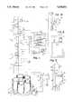
- FIG. 1is a perspective view, partially diagrammatic and not all to the same scale, of the system of the prior art with a turntable platform and one control panel greatly enlarged.
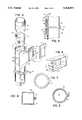
- FIG. 2is a perspective view of a section of the invention with portions broken away and the bezel displaced.
- FIG. 3is a sectional view, taken through line 3--3 of FIG. 2.
- FIG. 4is a perspective view of a housing of the invention.
- FIG. 5is a side elevation view of portion of a chute of the invention.
- FIG. 6is a front elevation view of a bezel of the invention.
- FIG. 7is a concrete pour ring form.
- FIG. 8is a sectional view of another embodiment of the invention.
- FIG. 9is a sectional view of a joint of another embodiment of the invention.
- FIG. 10is a perspective view of another embodiment of the invention.
- a waste chute ihas an access door 2 on each floor 3 of a multi-story building. These structures may be of the type well known in the art.
- a tenant 9carries a container 10 of separated waste to the access door 2 on his floor.
- control housing and panel 11mounted on a wall adjacent door 2, he pushes pushbutton 14 to select a receptacle 7 in the basement to correspond to the type of waste he wishes to dispose (paper in this case). All the control panels are operatively connected to central control 12 by conduits.
- a platform 4holds a set of waste receptacles 7, one for each type of separated waste, such as clear glass, colored glass, aluminum, paper and all other wastes or garbage.
- the movable platform 4is a turntable that is rotated by motor 5.
- a position sensor 6senses the rotary position of the platform 4.
- the central control 12operates the motor 5 that cooperates with the position sensor 6 in a servo relationship to rotate the platform 4 until the selected (paper) receptacle is directly beneath chute 7.
- a door sensor and lock assembly 13 at each door 2is also connected to the central control 12. While the platform is moving, the central control 12 actuates all the door locks to prevent waste falling while receptacles are moving. If any door is open, its door sensor will communicate that information to the central control 12 which may inhibit operation of motor 5 and platform motion.
- a duplicate panel 11 in the basementfacilitates service and indicates which door has been left open.
- a control switch 17provides for disabling the controls on the floors while emptying the receptacles, which illuminates the "out of service” lights 29.
- a power supply 19 for the systemis powered by the line power and the electronic controls in the central control 12 may be of the programmed microprocessor type with multiple inputs that is well known in the art. It may indicate service problems and may telephone for service.
- the receptacles 7may be provided with wheels 20 for ease in rolling down ramp 21 when full.
- the inventioncomprises a plurality of modular chute assembly sections 36 having a tubular shape with a vertical axial bore 31 having a circular cross section 50.
- Affixed to the outside of the sidewall 34is a conduit 22 for protectively carrying wires between floors and to the basement control.
- a support bracket 53supports an individual section 36 on a floor (not shown).
- a radially outward distention of the sidewallforms a protuberance 35 provided with a vertical portal 38.
- the portal 38is provided with a rigid frame assembly 37.
- a self closing door 2is hingedly connected to a first edge 39 of the frame.
- a housing 41is rigidly attached to the frame at another edge 40.
- Wires 28interconnect the electronics in the housing from one floor to other floors and the basement as desired. To provide the necessary protection to the wiring from trauma and fire, the interconnecting wires pass through upper conduit portion 26 and lower conduit portion 27. These wires terminate in plug together connectors.
- the connectors 48are contained within terminal receptacles 55. These receptacles slide along the conduit and can be locked in place on the conduit with locking collar 49.
- the connectorWhen being transported as individual sections 36, the connector is protectively within its receptacle and the receptacle is locked on the conduit protectively so that it does not protrude beyond the end 32 or 33 of the tubular sidewall.
- the receptaclesWhen the sections are installed and joined together, then the wires of each section are plugged together with connectors 48, the receptacles are unlocked and sidingly joined together and then locked onto their conduits to provide electrically secure conduit continuity.
- the tubular sectionsmay join together in a nesting or telescoping joint 52 in which a downstream end 33 has a reduced diameter that slides into an enlarged upstream end 32.
- a unitary bezel 42bolts onto the frame assembly 37 and covers the housing and frame with a finished appearance and apertures for the necessary indicator lights and control buttons or switches.
- a form ring 18may be provided to furnish an aperture configured to pass the sidewall and also the attached conduit.
- the tubular sectionmay have a variety of cross sectional shape s.
- FIG. 8shows a rectangular tubular sidewall.
- FIG. 9shows a flange joint 54 between an upstream end 32 and a downstream end 33 of two sections.
- the conduits 22terminate in sliding receptacles 55 which lock onto the conduits with locking means 49.
- the flange jointis secured with flange bolts 56.
- FIG. 10shows an embodiment of the invention in which the door 2 opens from one side 39 and the housing 41 is mounted on the opposite side.
- the section 36has a protuberance 35 which terminates in a circular opening with a circular door 2.
Landscapes
- Engineering & Computer Science (AREA)
- Structural Engineering (AREA)
- Mechanical Engineering (AREA)
- Refuse Collection And Transfer (AREA)
Abstract
Description
Claims (26)
Priority Applications (3)
| Application Number | Priority Date | Filing Date | Title |
|---|---|---|---|
| US08/585,643US5568871A (en) | 1996-01-16 | 1996-01-16 | Door and chute for separated waste control |
| AU11267/97AAU1126797A (en) | 1996-01-16 | 1996-12-02 | Door and chute for separated waste control |
| PCT/US1996/019123WO1997026092A1 (en) | 1996-01-16 | 1996-12-02 | Door and chute for separated waste control |
Applications Claiming Priority (1)
| Application Number | Priority Date | Filing Date | Title |
|---|---|---|---|
| US08/585,643US5568871A (en) | 1996-01-16 | 1996-01-16 | Door and chute for separated waste control |
Publications (1)
| Publication Number | Publication Date |
|---|---|
| US5568871Atrue US5568871A (en) | 1996-10-29 |
Family
ID=24342324
Family Applications (1)
| Application Number | Title | Priority Date | Filing Date |
|---|---|---|---|
| US08/585,643Expired - LifetimeUS5568871A (en) | 1996-01-16 | 1996-01-16 | Door and chute for separated waste control |
Country Status (3)
| Country | Link |
|---|---|
| US (1) | US5568871A (en) |
| AU (1) | AU1126797A (en) |
| WO (1) | WO1997026092A1 (en) |
Cited By (19)
| Publication number | Priority date | Publication date | Assignee | Title |
|---|---|---|---|---|
| WO1997038922A1 (en)* | 1996-04-17 | 1997-10-23 | Hi-Rise Recycling Systems Inc. | Modular trash chute and room for multistory building |
| US20020020619A1 (en)* | 1997-09-17 | 2002-02-21 | Kelly Fetzer | Remotely operable pressure vessel system |
| US20050116022A1 (en)* | 2003-09-19 | 2005-06-02 | Mallett Scott R. | Waste sorting network |
| US7275645B2 (en) | 2003-09-19 | 2007-10-02 | Vesta Medical, Llc | Handheld medical waste sorting device |
| US7303081B2 (en) | 2003-09-19 | 2007-12-04 | Vesta Medical, Llc | Handheld medical waste sorting method |
| US7311207B2 (en) | 2003-09-19 | 2007-12-25 | Vesta Medical, Llc | System for sorting discarded and spent pharmaceutical items |
| US7318529B2 (en) | 2003-09-19 | 2008-01-15 | Vest Medical, Llc | Method for sorting discarded and spent pharmaceutical items |
| US7562025B2 (en) | 2003-09-19 | 2009-07-14 | Vesta Medical, Llc | Waste sorting system with query function, and method thereof |
| US7660724B2 (en) | 2003-09-19 | 2010-02-09 | Vesta Medical, Llc | Waste sorting system utilizing removable liners |
| US7970722B1 (en) | 1999-11-08 | 2011-06-28 | Aloft Media, Llc | System, method and computer program product for a collaborative decision platform |
| US8195328B2 (en) | 2003-09-19 | 2012-06-05 | Vesta Medical, Llc | Combination disposal and dispensing apparatus and method |
| US9272846B2 (en) | 2011-11-22 | 2016-03-01 | Charlton L. George | Conveyor chute for the interior of a building and method of palletizing same for shipment |
| US20160097206A1 (en)* | 2014-10-02 | 2016-04-07 | Precision Airconvey Corporation | Material handling system with queue chute |
| US9534401B2 (en) | 2011-11-22 | 2017-01-03 | Charlton L. George | Conveyor chute for the interior of a building and method of palletizing same for shipment |
| CN106742911A (en)* | 2017-01-05 | 2017-05-31 | 刘小成 | A kind of garbage recovery device based on intelligent classification |
| CN109305536A (en)* | 2018-10-26 | 2019-02-05 | 广东恒新建设有限公司 | A kind of building waste Transporting equipment |
| US11078711B1 (en)* | 2016-06-23 | 2021-08-03 | Elcon, Inc. | Methods and systems for automatically determining level of unclosed door in chute applications |
| US11104512B2 (en) | 2016-07-15 | 2021-08-31 | Cleanrobotics Technologies, Inc. | Automatic sorting of waste |
| US20220009706A1 (en)* | 2019-01-24 | 2022-01-13 | Repod S.R.L. | Apparatus for the separate collection of rubbish |
Citations (11)
| Publication number | Priority date | Publication date | Assignee | Title |
|---|---|---|---|---|
| US3658242A (en)* | 1968-09-24 | 1972-04-25 | Ontwerp En Exploitatiebureau S | Tipping lock for a garbage chute |
| US4640403A (en)* | 1985-02-13 | 1987-02-03 | Mcdermott Daniel R | Gravity-conveyor chute section |
| US5031829A (en)* | 1990-07-23 | 1991-07-16 | Mark Shantzis | Separated waste collection system for multi-story building |
| US5083704A (en)* | 1990-08-06 | 1992-01-28 | George Rounthwaite | Trash disposal system |
| US5090546A (en)* | 1988-12-07 | 1992-02-25 | Trihard, S.A. | Door/ledge assembly for gravity chute |
| US5228577A (en)* | 1992-03-17 | 1993-07-20 | Wilson Terry D | Apparatus for separating household trash |
| US5253766A (en)* | 1990-04-05 | 1993-10-19 | Sims Geoffrey B | Waste disposal chute |
| US5257577A (en)* | 1991-04-01 | 1993-11-02 | Clark Melvin D | Apparatus for assist in recycling of refuse |
| FR2691384A1 (en)* | 1992-05-19 | 1993-11-26 | Tallet Gerard | Individual and collective sorting equipment for household rubbish - uses compartmented motorised kitchen carousel to receive categorised rubbish, later dispatched to communal carousel for collection. |
| US5271507A (en)* | 1992-10-16 | 1993-12-21 | Evans Jr Edward P | Storage disposal system for recyclable waste products |
| US5492227A (en)* | 1994-06-29 | 1996-02-20 | Millette; Robert T. | Segregation and storage apparatus for recyclables |
- 1996
- 1996-01-16USUS08/585,643patent/US5568871A/ennot_activeExpired - Lifetime
- 1996-12-02WOPCT/US1996/019123patent/WO1997026092A1/enactiveApplication Filing
- 1996-12-02AUAU11267/97Apatent/AU1126797A/ennot_activeAbandoned
Patent Citations (12)
| Publication number | Priority date | Publication date | Assignee | Title |
|---|---|---|---|---|
| US3658242A (en)* | 1968-09-24 | 1972-04-25 | Ontwerp En Exploitatiebureau S | Tipping lock for a garbage chute |
| US4640403A (en)* | 1985-02-13 | 1987-02-03 | Mcdermott Daniel R | Gravity-conveyor chute section |
| US5090546A (en)* | 1988-12-07 | 1992-02-25 | Trihard, S.A. | Door/ledge assembly for gravity chute |
| US5253766A (en)* | 1990-04-05 | 1993-10-19 | Sims Geoffrey B | Waste disposal chute |
| US5031829A (en)* | 1990-07-23 | 1991-07-16 | Mark Shantzis | Separated waste collection system for multi-story building |
| WO1992001615A1 (en)* | 1990-07-23 | 1992-02-06 | Shantzis Mark D | Separated waste collection system for multi-story building |
| US5083704A (en)* | 1990-08-06 | 1992-01-28 | George Rounthwaite | Trash disposal system |
| US5257577A (en)* | 1991-04-01 | 1993-11-02 | Clark Melvin D | Apparatus for assist in recycling of refuse |
| US5228577A (en)* | 1992-03-17 | 1993-07-20 | Wilson Terry D | Apparatus for separating household trash |
| FR2691384A1 (en)* | 1992-05-19 | 1993-11-26 | Tallet Gerard | Individual and collective sorting equipment for household rubbish - uses compartmented motorised kitchen carousel to receive categorised rubbish, later dispatched to communal carousel for collection. |
| US5271507A (en)* | 1992-10-16 | 1993-12-21 | Evans Jr Edward P | Storage disposal system for recyclable waste products |
| US5492227A (en)* | 1994-06-29 | 1996-02-20 | Millette; Robert T. | Segregation and storage apparatus for recyclables |
Non-Patent Citations (1)
| Title |
|---|
| Acme Chute Co. Inc. 4 Page Brochure. (No Date).* |
Cited By (50)
| Publication number | Priority date | Publication date | Assignee | Title |
|---|---|---|---|---|
| WO1997038922A1 (en)* | 1996-04-17 | 1997-10-23 | Hi-Rise Recycling Systems Inc. | Modular trash chute and room for multistory building |
| US5695115A (en)* | 1996-04-17 | 1997-12-09 | Shantzis; Mark D. | Modular trash chute and room for multistory building |
| US20020020619A1 (en)* | 1997-09-17 | 2002-02-21 | Kelly Fetzer | Remotely operable pressure vessel system |
| US6423188B1 (en)* | 1997-09-17 | 2002-07-23 | Automated Connectors Holdings, L.P. | Method and apparatus of controlling loose material that exits a coke drum |
| US7970722B1 (en) | 1999-11-08 | 2011-06-28 | Aloft Media, Llc | System, method and computer program product for a collaborative decision platform |
| US8005777B1 (en) | 1999-11-08 | 2011-08-23 | Aloft Media, Llc | System, method and computer program product for a collaborative decision platform |
| US8160988B1 (en) | 1999-11-08 | 2012-04-17 | Aloft Media, Llc | System, method and computer program product for a collaborative decision platform |
| US7533029B2 (en) | 2003-09-19 | 2009-05-12 | Vesta Medical, Llc | Waste sorting system for rendering drugs non-recoverable |
| US7617113B2 (en) | 2003-09-19 | 2009-11-10 | Vesta Medical, Llc | Medical waste sorting method |
| US7123150B2 (en) | 2003-09-19 | 2006-10-17 | Vesta Medical, Llc | Waste container identification system |
| US7126480B2 (en) | 2003-09-19 | 2006-10-24 | Vesta Medical, Llc | Waste sorting network |
| US7138918B2 (en) | 2003-09-19 | 2006-11-21 | Vesta Medical, Llc | System for sorting waste |
| US7275645B2 (en) | 2003-09-19 | 2007-10-02 | Vesta Medical, Llc | Handheld medical waste sorting device |
| US7296688B2 (en) | 2003-09-19 | 2007-11-20 | Vesta Medical, Llc | Apparatus for facilitating medical waste disposal |
| US7303081B2 (en) | 2003-09-19 | 2007-12-04 | Vesta Medical, Llc | Handheld medical waste sorting method |
| US7303080B2 (en) | 2003-09-19 | 2007-12-04 | Vesta Medical, Llc | Waste sensor for a disposable container |
| US7303082B2 (en) | 2003-09-19 | 2007-12-04 | Vesta Medical, Llc | Medical waste sorting system with container identification |
| US7311207B2 (en) | 2003-09-19 | 2007-12-25 | Vesta Medical, Llc | System for sorting discarded and spent pharmaceutical items |
| US7318529B2 (en) | 2003-09-19 | 2008-01-15 | Vest Medical, Llc | Method for sorting discarded and spent pharmaceutical items |
| US7341147B2 (en) | 2003-09-19 | 2008-03-11 | Vesta Medical, Llc | Disposable container for use in a waste sorting system |
| US7383195B2 (en) | 2003-09-19 | 2008-06-03 | Vesta Medical, Llc | Methods of sorting waste |
| US7454358B2 (en) | 2003-09-19 | 2008-11-18 | Vesta Medical, Llc | Waste scanning method |
| US7483837B2 (en) | 2003-09-19 | 2009-01-27 | Vesta Medical, Llc | Waste sensing system |
| US7487100B2 (en) | 2003-09-19 | 2009-02-03 | Vesta Medical, Llc | Method of sorting regulated drug waste |
| US20050116022A1 (en)* | 2003-09-19 | 2005-06-02 | Mallett Scott R. | Waste sorting network |
| US7533028B2 (en) | 2003-09-19 | 2009-05-12 | Vesta Medical, Llc | Waste sorting method for rendering drugs non-recoverable |
| US7562025B2 (en) | 2003-09-19 | 2009-07-14 | Vesta Medical, Llc | Waste sorting system with query function, and method thereof |
| US7565299B2 (en) | 2003-09-19 | 2009-07-21 | Vesta Medical, Llc | Waste sorting and tracking system and method |
| US7119689B2 (en) | 2003-09-19 | 2006-10-10 | Vesta Medical, Llc | System and method for sorting medical waste for disposal |
| US7620559B2 (en) | 2003-09-19 | 2009-11-17 | Vesta Medical, Llc | System for facilitating medical waste disposal |
| US7660724B2 (en) | 2003-09-19 | 2010-02-09 | Vesta Medical, Llc | Waste sorting system utilizing removable liners |
| US7664656B2 (en) | 2003-09-19 | 2010-02-16 | Mallett Scott R | Method of sorting waste utilizing removable liners |
| US8195328B2 (en) | 2003-09-19 | 2012-06-05 | Vesta Medical, Llc | Combination disposal and dispensing apparatus and method |
| US8204620B2 (en) | 2003-09-19 | 2012-06-19 | Vesta Medical, Llc | Method for combined disposal and dispensing of medical items |
| US8296243B2 (en) | 2003-09-19 | 2012-10-23 | Vesta Medical, Llc | Systems for identifying and categorizing medical waste |
| US8355994B2 (en) | 2003-09-19 | 2013-01-15 | Vesta Medical Llc | Sorting system for composite drugs |
| US8560460B2 (en) | 2003-09-19 | 2013-10-15 | Carefusion 303, Inc. | Automated waste sorting system |
| US8595021B2 (en) | 2003-09-19 | 2013-11-26 | Carefusion 303, Inc. | Methods for identifying and categorizing medical waste |
| US8868434B2 (en) | 2003-09-19 | 2014-10-21 | Carefusion 303, Inc. | Waste sorting and disposal method using labels |
| US9272846B2 (en) | 2011-11-22 | 2016-03-01 | Charlton L. George | Conveyor chute for the interior of a building and method of palletizing same for shipment |
| US9534401B2 (en) | 2011-11-22 | 2017-01-03 | Charlton L. George | Conveyor chute for the interior of a building and method of palletizing same for shipment |
| US20160097206A1 (en)* | 2014-10-02 | 2016-04-07 | Precision Airconvey Corporation | Material handling system with queue chute |
| US9725253B2 (en) | 2014-10-02 | 2017-08-08 | Precision Airconvey Corporation | Material handling system with queue chute |
| US11078711B1 (en)* | 2016-06-23 | 2021-08-03 | Elcon, Inc. | Methods and systems for automatically determining level of unclosed door in chute applications |
| US11104512B2 (en) | 2016-07-15 | 2021-08-31 | Cleanrobotics Technologies, Inc. | Automatic sorting of waste |
| CN106742911A (en)* | 2017-01-05 | 2017-05-31 | 刘小成 | A kind of garbage recovery device based on intelligent classification |
| CN106742911B (en)* | 2017-01-05 | 2017-11-14 | 刘小成 | A kind of garbage recovery device based on intelligent classification |
| CN109305536A (en)* | 2018-10-26 | 2019-02-05 | 广东恒新建设有限公司 | A kind of building waste Transporting equipment |
| US20220009706A1 (en)* | 2019-01-24 | 2022-01-13 | Repod S.R.L. | Apparatus for the separate collection of rubbish |
| US11964817B2 (en)* | 2019-01-24 | 2024-04-23 | Repod S.R.L. | Apparatus for the separate collection of rubbish |
Also Published As
| Publication number | Publication date |
|---|---|
| AU1126797A (en) | 1997-08-11 |
| WO1997026092A1 (en) | 1997-07-24 |
Similar Documents
| Publication | Publication Date | Title |
|---|---|---|
| US5568871A (en) | Door and chute for separated waste control | |
| US5031829A (en) | Separated waste collection system for multi-story building | |
| US4651544A (en) | Exterior entry door tethered key safe | |
| US4101877A (en) | Mail delivery alarm system | |
| CA2018784A1 (en) | Universal recreational vehicle toilet system with removable holding tank | |
| US5551576A (en) | Disposal system foe use in tall buildings | |
| US5209323A (en) | Interior fire escape chute for a building | |
| US5695115A (en) | Modular trash chute and room for multistory building | |
| US5190165A (en) | Method and apparatus for facilitating the collection of separated waste in multi-story buildings | |
| US3733763A (en) | Modular building and service tower therefor | |
| JPH05504536A (en) | Equipment for separating household waste | |
| US2901130A (en) | Automotive vehicle underground storage device | |
| US5458287A (en) | Prefabricated bay window conservatory enclosure for recyclable waste receptacles | |
| DE4302568A1 (en) | Multi-bin domestic-refuse-collection system | |
| US5579888A (en) | Coin collection arrangements | |
| US6341468B1 (en) | Building with attic module | |
| US4850784A (en) | Cross flow multilevel parking system | |
| KR100710616B1 (en) | Delivery device and method | |
| CH694811A5 (en) | Internet connectable multi user system service box for accessing goods ordering | |
| CN216281235U (en) | Modular commercial storehouse of connection on wisdom lamp pole | |
| DK2031152T3 (en) | MODULAR sanitary SYSTEM | |
| US3104019A (en) | Apparatus for garaging or storing motor vehicles | |
| JP2504884B2 (en) | Room under the stairs | |
| EP0086198A1 (en) | Improvements in or relating to construction of service units | |
| JPH085932Y2 (en) | Garbage carrier |
Legal Events
| Date | Code | Title | Description |
|---|---|---|---|
| STCF | Information on status: patent grant | Free format text:PATENTED CASE | |
| AS | Assignment | Owner name:HI-RISE RECYCLING SYSTEMS, INC., FLORIDA Free format text:ASSIGNMENT OF ASSIGNORS INTEREST;ASSIGNOR:SHANTZIS, MARK D.;REEL/FRAME:009638/0866 Effective date:19981028 | |
| AS | Assignment | Owner name:GENERAL ELECTRIC CAPITAL CORPORATION, AS ADMINISTR Free format text:SECURITY AGREEMENT;ASSIGNOR:HI-RISE RECYCLING SYSTEMS, INC.;REEL/FRAME:009827/0641 Effective date:19981028 | |
| AS | Assignment | Owner name:GENERAL ELECTRIC CAPITAL CORPORATION, AS ADMINISTR Free format text:SECURITY INTEREST;ASSIGNOR:HI-RISE RECYCLING SYSTEMS, INC.;REEL/FRAME:009950/0506 Effective date:19981028 | |
| FEPP | Fee payment procedure | Free format text:PAYOR NUMBER ASSIGNED (ORIGINAL EVENT CODE: ASPN); ENTITY STATUS OF PATENT OWNER: LARGE ENTITY | |
| FEPP | Fee payment procedure | Free format text:PAT HLDR NO LONGER CLAIMS SMALL ENT STAT AS SMALL BUSINESS (ORIGINAL EVENT CODE: LSM2); ENTITY STATUS OF PATENT OWNER: LARGE ENTITY | |
| FPAY | Fee payment | Year of fee payment:4 | |
| AS | Assignment | Owner name:WILKINSON-HI-RISE, LLC, NORTH CAROLINA Free format text:ASSIGNMENT OF ASSIGNORS INTEREST;ASSIGNORS:HI-RISE RECYCLING SYSTEMS, INC.;IDC ACQUISITION SUB, INC.;ACME CHUTE COMPANY, INC.;AND OTHERS;REEL/FRAME:012762/0005 Effective date:20020108 | |
| AS | Assignment | Owner name:GENERAL ELECTRIC CAPITAL CORPORATION, CONNECTICUT Free format text:SECURITY AGREEMENT;ASSIGNOR:WILKINSON-HI-RISE, LLC;REEL/FRAME:013352/0823 Effective date:20011227 | |
| FPAY | Fee payment | Year of fee payment:8 | |
| FPAY | Fee payment | Year of fee payment:12 | |
| REMI | Maintenance fee reminder mailed |